

Page 1
ADMINISTRATION
Cisco Small Business
SG200 Series 8-port Smart Switches
GUIDE
Page 2

Contents
Chapter 1: Getting Started 8
Starting the Web-Based Switch Configuration Utility 8
Launching the Utility 9
Logging In 9
Logging Out 10
Quick Start Device Configuration 11
Window Navigation 12
Application Header 12
Other Resources 13
Navigation Window 14
Management Buttons 14
Chapter 2: Viewing Statistics 18
System Summary 18
Displaying the System Summary 18
Configuring System Settings 21
Interface Statistics 22
Etherlike Statistics 23
802.1X EAP Statistics 24
IPv6 DHCP Statistics 25
RADIUS Statistics 26
RMON 27
Logs 29
RAM Memory Log 29
Flash Memory Log 30
Chapter 3: Administration 32
Configuring System Settings 33
Management Interface 34
Configuring an IPv4 Management Interface 34
Configuring an IPv6 Management Interface 36
Cisco Small Business SG200 Series 8-port Smart Switch 2
Page 3

Adding IPv6 Addresses 36
IPv6 Default Router Table 37
Viewing and Adding IPv6 Neighbors 38
Contents
Managing User Accounts 39
Adding a User 39
Changing a User Password 40
Deleting a User 41
Enabling Management Services 42
Configuring the Idle Session Timeout 42
Login Sessions 42
Login History 43
Time Settings 43
Setting System Time 43
Configuring the SNTP Setting 46
Configuring SNTP Authentication 50
System Logs 51
Configuring Log Settings 52
Configuring Remote Log Servers 53
File Management 54
Upgrading and Backing Up Firmware and Language Files 56
Downloading and Backing Up the Configuration and Log Files 58
Downloading a Configuration File to Restore Settings 58
Backing Up the Configuration File and Logs 59
Delete Configuration 61
Copying and Saving Configuration Files 61
DHCP Auto Configuration 62
Overview 63
DHCP Server Message Details 63
Alternate TFTP Server and File Name 64
Configuration File Download Details 64
Setting DHCP Auto Configuration 67
Firmware Recovery Over HTTP 69
Downloading an Image or Boot Code File From the System Boot Prompt 71
Cisco Small Business SG200 Series 8-port Smart Switch 3
Page 4

Downloading an Image or Boot Code File Using TFTP 71
Downloading an Image or Boot Code File Using XMODEM 72
Contents
Rebooting the Switch 74
Pinging Hosts 74
Configuring Control Packet Forwarding 75
Diagnostics 76
Testing Copper Ports 77
Configuring Port Mirroring 78
CPU/Memory Utilization 80
Enabling Bonjour 80
LLDP-MED 81
Configuring Global LLDP-MED Properties 82
Configuring LLDP-MED on a Port 83
LLDP-MED Port Status Details 85
LLDP-MED Neighbor Information 87
Configuring DHCP Client Vendor Options 89
Chapter 4: Port Management 90
Configuring Port Settings 90
Link Aggregation 92
Configuring LAGs 92
Configuring LAG Settings 93
Configuring LACP 94
Configuring PoE 96
Configuring PoE Properties 96
Configuring PoE Port Settings 98
Green Ethernet 100
Configuring Green Ethernet Properties 100
Configuring Green Ethernet Port Settings 101
Chapter 5: VLAN Management 103
Creating VLANs 104
Cisco Small Business SG200 Series 8-port Smart Switch 4
Page 5

Contents
Configuring VLAN Interface Settings 104
Changing the Interface VLAN Mode 106
Configuring VLAN Membership 108
Configuring Port to VLAN 109
Configuring Port VLAN Membership 110
Setting the Default VLAN 111
Voice and Media 112
Displaying and Adding Telephony OUI 113
Configuring OUI Based Voice and Media 113
Configuring SIP/H323 Based Voice and Media 114
Media VLAN 115
Auto VoIP Sessions 117
Chapter 6: Spanning Tree 118
Overview of Spanning Tree 118
Configuring STP Status and Global Settings 119
Configuring Global and Bridge Settings 119
Configuring STP Interface Settings 121
RSTP Interface Settings 123
Chapter 7: MAC Address Tables 127
Configuring Static MAC Addresses 127
Configuring the Aging Time for Dynamic Addresses 129
Dynamic MAC Addresses 129
Chapter 8: Multicast 131
Multicast Properties 132
Configuring a Multicast Forwarding Mode on all VLANs 132
Configuring Multicast Properties on an Individual VLAN 133
Configuring MAC Group Addresses 133
Viewing the MAC Group Address Table 134
Adding a Static MAC Group Address Table Entry 134
Cisco Small Business SG200 Series 8-port Smart Switch 5
Page 6

Configuring MAC Address Group Port Membership 135
Contents
Configuring Group-to-Port 135
Configuring IGMP Snooping 136
Configuring MLD Snooping 138
Configuring IGMP Multicast Router Interfaces 140
Configuring MLD Multicast Router Interfaces 141
Chapter 9: IP Configuration 142
ARP Table 142
Domain Name System 142
Configuring DNS Servers 143
Configuring Global DNS Settings 143
Adding DNS Servers 144
Hostname Mapping 144
Configuring Static DNS Mappings 144
Viewing and Deleting Dynamic DNS Entries 145
Chapter 10: Security 146
RADIUS 146
Configuring Global RADIUS Settings 147
Adding a RADIUS Server 147
Password Strength 149
Management Access Profile Rules 150
Configuring an Access Profile and Rules 150
Modifying and Deleting Access Profiles and Rules 152
Authentication Methods 153
Storm Control 154
Port Security 155
Enabling Port Security 155
Viewing and Configuring Secure MAC Addresses 157
802.1X 157
Defining 802.1X Properties 158
Cisco Small Business SG200 Series 8-port Smart Switch 6
Page 7

Modifying Port PAE Capabilities 159
Configuring Port Authentication 160
Configuring Supplicant Port Authentication 162
Displaying Authenticated Hosts 163
Contents
Chapter 11: Quality of Service 164
QoS Properties 165
Defining Queues 166
Queue Configuration Recommendations 167
Configuring Queues 167
Mapping CoS/802.1p Priorities to Queues 168
Mapping IP Precedence to Queues 170
Mapping DSCP Values to Queues 171
Defining Rate Limit Profiles 172
Applying Rate Limit Profiles to Interfaces 173
Traffic Shaping 174
Cisco Small Business SG200 Series 8-port Smart Switch 7
Page 8

Getting Started
This chapter provides an introduction to the web-based switch configuration
utility and includes the following topics:
• Starting the Web-Based Switch Configuration Utility
• Quick Start Device Configuration
• Window Navigation
1
Starting the Web-Based Switch Configuration Utility
This section describes how to navigate the web-based switch configuration utility.
Browsers have the following restrictions:
• If you are using Internet Explorer 8, open a browser window and configure
the following settings:
Click To ol s > Internet Options and then select the Security tab. Select
Local Intranet and click Sites. Click Advanced and then click Add. Add the
intranet address of the switch (http://<ip-address>) to the local intranet
zone. The IP address can also be specified as the subnet IP address, so that
all addresses in the subnet are added to the local intranet zone.
• If you are using Internet Explorer 6, you cannot directly use an IPv6 address
to access the switch. You can, however, use the Domain Name System
(DNS) server to create a domain name that contains the IPv6 address, and
then use that domain name in the address bar in place of the IPv6 address.
• If you have multiple IPv6 interfaces on your management station, use the
IPv6 global address instead of IPv6 link local address to access the switch
from your browser.
• Screen resolutions at 800x600 or lower in Internet Explorer browsers and
Firefox 3.6 are not supported by the web-based switch configuration utility.
Cisco Small Business SG200 Series 8-port Smart Switch 8
Page 9

Getting Started
Starting the Web-Based Switch Configuration Utility
Launching the Utility
To open the web-based switch configuration utility:
STEP 1 Open a web browser.
STEP 2 Enter the IP address of the switch that you are configuring in the address bar on
the browser, and then press Enter. (The factory default IP address is
192.168.1.254.) The Log In page opens.
Logging In
To log in to the web-based switch configuration utility:
1
STEP 1 Enter the username and password. The factory default user name is cisco and the
default password is cisco.
Note: When the switch boots with the factory default configuration, the web-
based switch configuration utility appears in the default language. After you log in,
you can download additional languages by using the Upgrade/Backup Firmware/
Language page.
STEP 2 If this is the first time that you logged on with the default user name (cisco) and the
default password (cisco) or your password has expired, the Change Admin
Password page opens. Enter the new password, confirm it, click Apply, and then
click Close. (The characters ', ", %, and ? are not supported.) The new password is
saved.
NOTE Password complexity is enabled by default and the new password must comply to
the default password complexity rule defined by the password strength. (See
Adding a User for more information.) The password strength check can be
temporarily disabled by selecting the Disable Password Strength Enforcement
option.
STEP 3 Click Login.
When the login attempt is successful, the Getting Started page opens.
If you entered an incorrect user name or password, an error message is displayed
and the Log In page remains displayed on the screen.
NOTE When logging in by using HTTP or HTML, if you are provided an option to choose
from more than one network port, select the lowest number port.
Cisco Small Business SG200 Series 8-port Smart Switch 9
Page 10

Getting Started
!
Starting the Web-Based Switch Configuration Utility
Select Don’t show this page on startup to prevent the Getting Started page from
being displayed each time that you logon to the system. If you select this option,
the System Summary page is opened instead of the Getting Started page.
Logging Out
By default, the application automatically logs you out after 10 minutes of inactivity.
See Configuring the Idle Session Timeouts for instructions on changing the
default timeout period.
To log out at any time, click Logout in the top right corner of any page.
CAUTION Unless the Running Configuration is copied to the Startup Configuration file type,
all changes made since the last time the file type was saved are lost if the switch is
rebooted. We recommend that you save the Running Configuration to the Startup
Configuration file type before logging off to preserve any changes you made
during this session.
1
A red X icon displayed to the left of the Save button indicates that Running
Configuration changes have been made that have not yet been saved to the Startup
Configuration file type.
When you click Save, the Download/Backup Configuration/Log page displays
(see Downloading and Backing Up the Configuration and Log Files). Save the
Running Configuration by copying it to the Startup Configuration file type. After this
save, the red X icon and the Save button no longer display.
Cisco Small Business SG200 Series 8-port Smart Switch 10
Page 11

Getting Started
Quick Start Device Configuration
Quick Start Device Configuration
To simplify device configuration through quick navigation, the Getting Started
page provides links to the most commonly-used pages.
Links on the Getting Started Page
Category Link Name (on the Page) Linked Page
Initial Setup Change Device IP Address IPv4 Interface
Create VLAN Create VLAN
Configure Port Settings Port Settings
1
Device
Status
Quick
Access
System Summary System Summary
Port Statistics Interface
RMON Statistics RMON Statistics
View Log RAM Memory
Change Device Password User Accounts
Upgrade Device Software Upgrade/Backup Firmware/
Language
Backup Device
Configuration
Configure QoS QoS Properties
Configure Port Mirroring Port Mirroring
Download/Backup Configuration/
Log
Cisco Small Business SG200 Series 8-port Smart Switch 11
Page 12
Getting Started
Window Navigation
Window Navigation
This section describes the features of the web-based switch configuration utility.
Application Header
The Application Header is displayed on every page. It provides the following
buttons:
Buttons
Name Description
1
The Syslog Alert Status button (red circle with an X) is
displayed when a new Syslog message, above the critical
severity level, is logged. Click to open the Status and
Statistics > View Log > RAM Memory Log page. After
you access this page, the Syslog Alert Status button is no
longer displayed.
A red X icon, displayed to the left of the Save button,
indicates that configuration changes have been made and
have not yet been saved to the Startup Configuration file.
When you click this button, the Download/Backup
Configuration/Log page displays. Save the Running
Configuration by copying it to the Startup Configuration
file type. After you click Apply to save this file, the red X
icon and the Save button are no longer displayed. When
the switch is rebooted, it copies the Startup Configuration
file type to the Running Configuration and sets the switch
parameters according to the data in the Running
Configuration.
User The name of the user logged on to the switch. The default
user name is cisco.
Language Menu Select a language or load a new language file into the
device. If the language required is displayed in the menu,
select it. If not, select Download Language. For more
information about adding a new language, refer to the
Upgrade/Backup Firmware/Language page.
Cisco Small Business SG200 Series 8-port Smart Switch 12
Page 13

Getting Started
Window Navigation
1
Buttons (Continued)
Name Description
Log Out Click to log out of the web-based switch configuration
utility.
About Click to display the switch type and switch version
number.
Help Click to display the online help.
Other Resources
You can use the following links on the Getting Started page for additional
information and assistance with using your switch:
• Support—Displays the support web page for Cisco Small Business
Managed Switches.
• Forums—Displays the web page for the Cisco Small Business Support
Community.
Cisco Small Business SG200 Series 8-port Smart Switch 13
Page 14
Getting Started
Window Navigation
1
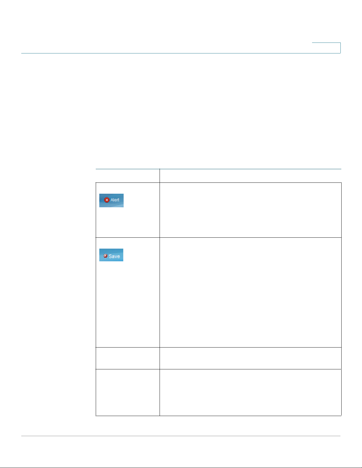
Navigation Window
A navigation window is located on the left side of each page. Click a top-level
category to display links to related pages. Links that are preceded by an arrow are
subcategories that expand to display the related page links.
Management Buttons
The following table describes the commonly-used buttons that appear on various
pages in the system.
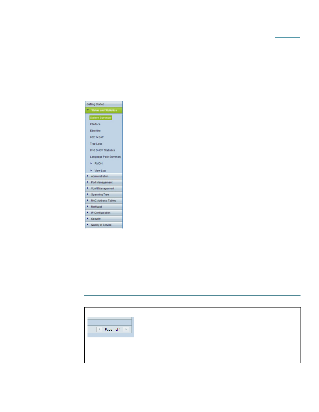
Management Buttons
Name Description
Depending on the number of pages and the currently
displayed page, use these features to navigate through
the pages of the table. Click |< to go to the first page,
click < to go to the previous page, click > to go to the
next page, and click >| to go to the last page. Use the
Page <number> of <number> drop-down list to choose
a particular page.
Cisco Small Business SG200 Series 8-port Smart Switch 14
Page 15
Getting Started
Window Navigation
1
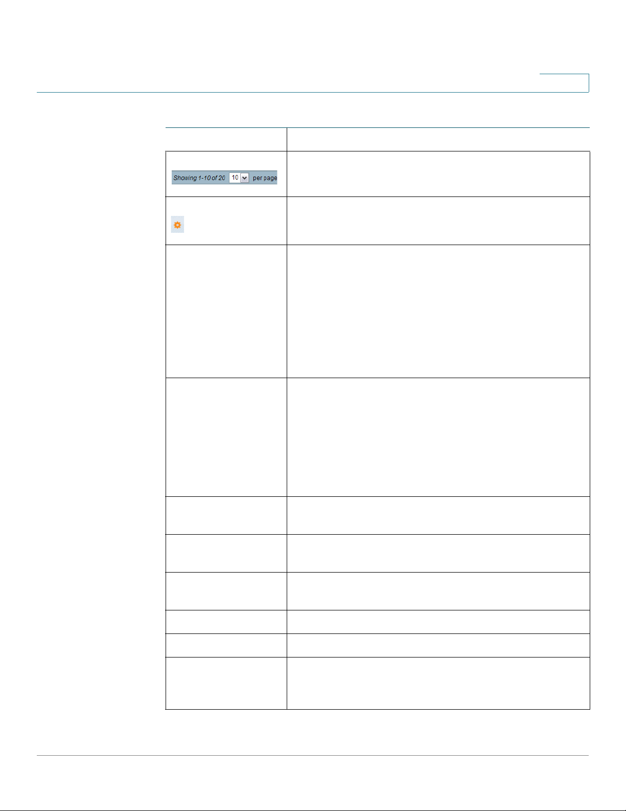
Management Buttons (Continued)
Name Description
Select the number of table entries to display on each
page.
Indicates a mandatory field.
Add Click to display the related Add page and add an entry
to a table. Enter the information and click Apply. Click
Close to return to the main page.
Note: Your changes are applied to the running
configuration only. If the switch is rebooted, the running
configuration is lost. To save your changes to the startup
configuration, click Save. For more information, see
Copying and Saving Configuration Files.
Apply Click to apply the changes that you entered on the
selected page.
Note: Your changes are applied to the running
configuration only. If the switch is rebooted, the running
configuration is lost. To save your changes to the startup
configuration, click Save. For more information, see
Copying and Saving Configuration Files.
Cancel Click to “undo” the changes that you made on the page
and to reset the values to the previously applied entries.
Clear All Interfaces
Counters
Clear Interface
Counters
Clear Logs Click to clear the log files.
Clear Table Click to clear the table entries.
Close Click to return to the main page. If there are changes that
Click to clear the statistic counters for all interfaces.
Click to clear the statistic counters for the selected
interface.
were not applied to the Running Configuration, a
message is displayed.
Cisco Small Business SG200 Series 8-port Smart Switch 15
Page 16

Getting Started
Window Navigation
1
Management Buttons (Continued)
Name Description
Copy Settings A table typically contains one or more entries containing
configuration settings. Instead of modifying each entry
individually, it is possible to modify one entry and then
copy it to multiple entries, as described below:
• Select the entry to be copied. Click Copy
Settings.
• Enter the destination entry numbers.
• Click Apply to save the changes to the Running
Configuration.
• Click Close to return to the main page.
Delete Select the entry in the table to be deleted and click
Delete. The entry is deleted.
Details Click to display details associated with the entry
selected on the main page.
Edit Select an entry and click Edit to open it for editing. The
Edit page opens, and the entry can be modified.
• Click Apply to save the changes to the Running
Configuration. (Note that there is no message to
confirm that the parameters have been saved to
the Running Configuration. This is normal
behavior.)
• Click Close to return to the main page.
Te st Click Te s t to perform related tests.
Clear Filter Click Clear Filter to redisplay data on a page with the
default criteria.
Go Click Go to filter the data displaying on a page using the
selected criteria.
Cisco Small Business SG200 Series 8-port Smart Switch 16
Page 17

Getting Started
Window Navigation
1
Management Buttons (Continued)
Name Description
Sort buttons If the This table is sortable message appears below a
table, each column heading is a sort button. Click a
column heading to sort the records in ascending order,
based on the contents of the selected column. After the
sort is applied, an arrow appears in the column heading.
You can click this arrow to reverse the sort order.
Cisco Small Business SG200 Series 8-port Smart Switch 17
Page 18

Viewing Statistics
This chapter describes how to display switch statistics.
It contains the following topics.
• System Summary
• Interface Statistics
• Etherlike Statistics
2
• 802.1X EAP Statistics
• IPv6 DHCP Statistics
• RADIUS Statistics
• Logs
System Summary
The System Summary page displays basic information such as the hardware
model description, software version, language packs, and system up time.
Displaying the System Summary
To view system information, click Status and Statistics > System Summary in the
navigation window. Or, click System Summary under Device Status on the
Getting Started page.
The System Summary page displays the following information:
• System Description—A description of the system.
• System Location—Physical location of the switch. Click Edit to display the
System Settings page and enter this value. (The characters ', ", %, and ? are
not supported.)
Cisco Small Business SG200 Series 8-port Smart Switch 18
Page 19

Viewing Statistics
System Summary
2
• System Contact—Name of a contact person. Click Edit to display the
System Settings page and enter this value. (The characters ', ", %, and ? are
not supported.)
• Hostname—Name of the switch. Click Edit to display the System Settings
page and enter this value. By default, the switch hostname is composed of
the word switch concatenated with the three least significant bytes of the
switch MAC address (the six furthest right hexadecimal digits).
• System Object ID—The base object ID for the system’s management
information base (MIB).
• System Uptime—Time that has elapsed since the last reboot.
• Current Time—Current system time.
• Base MAC Address—Switch MAC address.
Hardware and Firmware Version Information
The following hardware and software information displays for the switch:
• Serial Number—Serial number of the switch.
• PID VID—Part number and version ID.
• Boot Version—Version of the boot code.
• Maximum Available Power (W)—(PoE switches only) Maximum available
power that can be delivered by the PoE ports.
• Threshold Power—(PoE switches only) The amount of power that must be
available for delivery in order for the port to be powered up.
• Consumed Power—(PoE switches only) Power currently being delivered to
the PoE devices connected to the switch.
• Firmware Version—Firmware version number of the active image.
• Firmware MD5 Checksum—MD5 checksum of the active image.
• Boot MD5 Checksum—MD5 checksum of the boot code.
You can view settings for each switch port. To display the Port Settings page, click
the port.
Cisco Small Business SG200 Series 8-port Smart Switch 19
Page 20

Viewing Statistics
System Summary
2
Language Pack Table
This table displays information about the languages available on the switch. A
language can be selected by the administrator when logging into the configuration
utility.
English is the default language and it is built into the software. You can use the
Upgrade/Backup Firmware/Language page to download additional language
packs. Language files are available from the Cisco firmware download page.
The Language Pack Table displays the following information for each available
language:
• Language—Language name.
• Locale—Internet Engineering Task Force (IETF) locale code that identifies
the language and the country or region.
• Version—Language file version.
• MD5 Checksum—128-bit hash code used to check file integrity.
• File Size—The file size in KB.
• File Type—Indicates one of the following values:
- Built-In—Default language provided within the software and therefore
cannot be downloaded as a separate file.
- External—A language file that has been downloaded to the switch and
can be selected at login.
• Default—Displays Ye s to indicate that the web-based switch configuration
utility login page will display in this language whenever the switch is
rebooted.
• Status—Displays Active or Inactive. At log-in, the user can choose a
language. The selected language is the Active language.
• Number of Users—The number of management users currently logged in
and using this language.
TCP and UDP Services
This table lists the information for each service that uses TCP or UDP:
• Service Name—The commonly–used name of the service, if available, such
as HTTP.
• Type—The transport protocol used for this service (TCP or UDP).
Cisco Small Business SG200 Series 8-port Smart Switch 20
Page 21

Viewing Statistics
System Summary
2
• Port—The Internet Assigned Numbers Authority (IANA) port number for the
service.
• IP Address—The IP address, if any, of a remote device that is connected to
this service on the switch.
• Remote Port—The IANA port number of any remote device communicating
with this service.
• State—The state of the service. For UDP, only connections in the Active state
display in the table. In the Active state, a connection is established between
the switch and a client or server. The TCP states are:
- Listen—The service is listening for connection requests.
- Active—A connection session is established and packets are being
transmitted and received.
- Established—A connection session is established between the switch
and a server or client, depending on each device’s role with respect to
this protocol.
Configuring System Settings
To configure the system settings:
STEP 1 Click Status and Statistics > System Summary. The System Summary page
opens.
STEP 2 Click Edit to modify the following settings:
• System Location—Enter the location where the switch is physically located.
• System Contact—Enter the name of a contact person.
• Hostname—Enter the hostname. Use only letters, digits, and hyphens. Host
names cannot begin or end with a hyphen. No other symbols, punctuation
characters, or blank spaces are permitted (as specified in RFC1033,
RFC1034, and RFC1035). The default hostname is the word switch
followed by the last three octets of the base MAC address. For example, a
switch with a MAC address of 010203040506 has the default hostname
switch040506.
STEP 3 Click Apply. Your changes are saved to the Running Configuration.
Cisco Small Business SG200 Series 8-port Smart Switch 21
Page 22

Viewing Statistics
Interface Statistics
Interface Statistics
Use the Interface page to display statistics for received and transmitted packets.
To display this page, click Status and Statistics > Interface in the navigation
window, or click Port Statistics under Device Status on the Getting Started
page.
Select the interface (Port or LAG) for which you want to display statistics, then
select a refresh rate for the statistics. The following information displays for the
selected interface:
• To ta l By te s ( Oc te ts )—Total number of octets transmitted or received on the
• Unicast Packets—Total number of unicast packets transmitted or received
2
selected interface since the switch was last refreshed.
on the selected interface since the switch was last refreshed.
• Multicast Packets—Total number of multicast packets transmitted or
received on the selected interface since the switch was last refreshed.
• Broadcast Packets—Total number of broadcast packets transmitted or
received on the selected interface since the switch was last refreshed.
• Packets with Errors—Total number of packets with errors received on the
selected interface since the switch was last refreshed.
• STP BPDUs—Total number of Spanning Tree Protocol (STP) Bridge Protocol
Data Units (BPDUs) transmitted or received on the selected interface since
the switch was last refreshed.
• RSTP BPDUs—Total number of Rapid Spanning Tree Protocol BPDUs
transmitted or received on the selected interface since the switch was last
refreshed.
To clear statistics counters:
Click Clear Interface Counters to reset all counters to 0 for the selected
interface.
Click Clear All Interface Counters to reset all counters to 0 for all
interfaces.
Cisco Small Business SG200 Series 8-port Smart Switch 22
Page 23

Viewing Statistics
Etherlike Statistics
Etherlike Statistics
The system collects and reports statistics on ports and LAGs in accordance with
RFC2665.
To display this page, click Status and Statistics > Etherlike in the navigation
window.
Select the interface (Port or LAG) for which you want to display statistics, then
select a refresh rate for the statistics. These statistics are cumulative since the last
time the page was refreshed. The following information displays for the selected
interface:
• Frame Check Sequence (FCS) Errors—FCS errors received.
• Single Collision Frames—Signal collision frame errors received.
2
• Late Collisions—Late collision frames received.
• Excessive Collisions—Excessive collision frames received.
• Multiple Collisions—Multiple collision frames received.
• Oversize Packets—Packets received that were longer than 1518 octets
(excluding framing bits and including FCS octets) and were otherwise wellformed.
• Internal MAC Receive Errors—Internal MAC errors received on the LAG or
interface.
• Alignment Errors—Packets received with alignment errors
• Pause Frames Received—Pause frames received on the LAG or interface.
• Pause Frames Transmitted—Pause frames transmitted from the LAG or
interface.
To clear statistics counters:
Click Clear Interface Counters to reset all counters to 0 for the selected
interface.
Click Clear All Interface Counters to reset all counters to 0 for all
interfaces.
Cisco Small Business SG200 Series 8-port Smart Switch 23
Page 24

Viewing Statistics
802.1X EAP Statistics
802.1X EAP Statistics
The switch ports can be configured to use the IEEE 802.1X Extensible
Authentication Protocol (EAP) to control network access (see 802.1X). You can use
the 802.1X EAP page to display information about EAP packets received on a port.
To display the 802.1X EAP page, click Status and Statistics > 802.1X EAP in the
navigation window.
STEP 1 Select the Port for which you want to display statistics.
STEP 2 Select a Refresh Rate for the statistics. These statistics are cumulative since the
last time the page was refreshed.
The following information displays for the selected interface:
2
• EAPOL Frames Received—Valid Extensible Authentication Protocol over
LAN (EAPOL) frames received on the port.
• EAPOL Frames Transmitted—EAPOL frames transmitted through the port.
• EAPOL Start Frames Received—EAPOL Start frames received on the port.
• EAPOL Logoff Frames Received—EAPOL Logoff frames received on the
port.
• Invalid EAPOL Frames Received—Unrecognized EAPOL frames received
on this port.
• EAP Length Error Frames Received—EAPOL frames with an invalid packet
body length received on this port.
To clear statistics counters:
Click Clear Interface Counters to reset all counters to 0 for the selected
interface.
Click Clear All Interface Counters to reset all counters to 0 for all
interfaces.
Cisco Small Business SG200 Series 8-port Smart Switch 24
Page 25

Viewing Statistics
IPv6 DHCP Statistics
IPv6 DHCP Statistics
The switch can be configured to allow management over an IPv6 interface, and to
receive its management IPv6 address through the Dynamic Host Configuration
Protocol (DHCPv6). See Management Interface for information on configuring
IPv6 and DHCP on the management interface. You can use the IPv6 DHCP
Statistics page to display information on transmitted and received DHCPv6
packets.
To display this page, click Status and Statistics > IPv6 DHCP Statistics in the
navigation window.
Select a refresh rate for the page. The page displays the following statistics, which
are cumulative since the last time the page refreshed.
• DHCPv6 Advertisement Packets Received
2
• DHCPv6 Reply Packets Received
• Received DHCPv6 Advertisement Packets Discarded
• Received DHCPv6 Reply Packets Discarded
• DHCPv6 Malformed Packets Received
• Total DHCPv6 Packets Received
• DHCPv6 Solicit Packets Transmitted
• DHCPv6 Request Packets Transmitted
• DHCPv6 Renew Packets Transmitted
• DHCPv6 Rebind Packets Transmitted
• DHCPv6 Release Packets Transmitted
• Total DHCPv6 Packets Transmitted
Click Clear Counters to reset all counters to 0.
Cisco Small Business SG200 Series 8-port Smart Switch 25
Page 26

Viewing Statistics
RADIUS Statistics
RADIUS Statistics
The switch can be configured to communicate with a RADIUS server for user
authentication. To display the RADIUS Statistics page, click
Status and Statistics > RADIUS Statistics in the navigation window.
Select a RADIUS server from the list and select a refresh rate for the page. The
page displays the following statistics, which are cumulative since the last time the
page refreshed.
• Access Requests—The number of Authentication-Request packets
• Access Retransmissions—Number of Authentication-Request packets
• Access Accepts—Number of Authentication-Request packets accepted
2
transmitted to the RADIUS server.
retransmitted to the RADIUS server.
by the RADIUS server.
• Access Rejects—Number of Authentication-Request packets rejected by
the RADIUS server.
• Access Challenges—Number of Access-Challenge packets sent by the
RADIUS server to the switch.
• Malformed Access Responses—Number of reply packets from the
RADIUS server that were malformed.
• Bad Authenticators—Number of Authentication-Request packets that
contained invalid Message Authenticator attributes.
• Pending Requests—Number of Authentication-Request packets that were
sent to the server and have not been replied to.
• Timeouts—Number of Authentication-Request packets that were timed out
due to no response from the server.
• Unknown Types—Number of RADIUS packets of unknown type that were
received by the switch.
• Packets Dropped—Number of RADIUS packets dropped by the switch.
Click Clear All Statistics to reset all counters to 0.
Cisco Small Business SG200 Series 8-port Smart Switch 26
Page 27

Viewing Statistics
RMON
RMON
2
RMON (Remote Networking Monitoring) is an SNMP specification that enables an
SNMP agent in the switch to monitor traffic statistics over a given period and send
traps to an SNMP manager. The local SNMP agent compares actual, real-time
counters against predefined thresholds and generates alarms, without the need
for polling by a central SNMP management platform. This is an effective
mechanism for proactive management, provided that you have right thresholds set
relative to your network base line.
RMON decreases the traffic between the manager and the switch because the
SNMP manager does not have to frequently poll the switch for information, and
enables the manager to get timely status reports because the switch reports
events as they occur. Use the RMON Statistics page to display details about
switch use, such as packet processing statistics and errors that have occurred on
the switch.
The RMON Statistics page displays detailed information regarding packet sizes
and information regarding physical layer errors. The information shown is
according to the RMON standard.
To view statistics:
STEP 1 Click Status and Statistics > RMON > Statistics in the navigation window.
STEP 2 Select the port or LAG for which you want to display statistics.
STEP 3 Select a refresh rate for the page.
The following information displays for the selected interface:
• Bytes Received—Octets received on the interface since the switch was last
refreshed. This number includes bad packets and FCS octets, but excludes
framing bits.
• Drop Events—Number of times that packets have been dropped on the
interface since the switch was last refreshed.
• Packets Received—Packets received on the interface, including bad
packets, multicast and broadcast packets, since the switch was last
refreshed.
• Broadcast Packets Received—Good broadcast packets received on the
interface since the switch was last refreshed. This number does not include
multicast packets.
Cisco Small Business SG200 Series 8-port Smart Switch 27
Page 28

Viewing Statistics
RMON
2
• Multicast Packets Received—Good multicast packets received on the
interface since the switch was last refreshed.
• CRC & Align Errors—CRC and Align errors that have occurred on the
interface since the switch was last refreshed.
• Undersize Packets—Undersized packets (less than 64 octets) received on
the interface since the switch was last refreshed.
• Oversize Packets—Oversized packets (over 1518 octets) received on the
interface since the switch was last refreshed.
• Fragments—Fragments (packets with less than 64 octets, excluding
framing bits, but including frame check sequence octets) received on the
interface since the switch was last refreshed.
• Jabbers—Packets received that were more than 1518 octets long and had
an FCS error during the sampling session.
• Collisions—Collisions received on the interface since the switch was last
refreshed.
• Frames of 64 Bytes—64-byte frames received on the interface since the
switch was last refreshed.
• Frames of 65 to 127 Bytes—65-byte to 127-byte frames received on the
interface since the switch was last refreshed.
• Frames of 128 to 255 Bytes—128-byte to 255-byte frames received on the
interface since the switch was last refreshed.
• Frames of 256 to 511 Bytes—256-byte to 511-byte frames received on
the interface since the switch was last refreshed.
• Frames of 512 to 1023 Bytes—512-byte to 1023-byte frames received on
the interface since the switch was last refreshed.
• Frames of 1024 to 1518 Bytes—1024-byte to 1518-byte frames received
on the interface since the switch was last refreshed.
Cisco Small Business SG200 Series 8-port Smart Switch 28
Page 29

Viewing Statistics
Logs
Logs
2
The switch generates messages to identify the state of the system and to assist in
diagnosing issues that arise during switch operation. Messages might be
generated in response to events, faults, or errors occurring on the platform and to
changes in configuration.
Logs of these messages are stored in RAM and flash memory. Entries in the flash
log—unlike those in RAM—are stored across reboots.
To access the log menu items, click Status and Statistics > View Log in the
navigation window. The log menu includes the following pages:
• RAM Memory Log
• Flash Memory Log
RAM Memory Log
Use the RAM Memory page to view information about specific RAM (cache) log
entries, including the time the log was entered, the log severity, and a description
of the log.
To display this page, click Status and Statistics > View Log > RAM Memory in
the navigation window.
NOTE This page might take up to 45 seconds to display when the table contains the
maximum number of entries.
The RAM Memory Log Table contains the following fields:
• Log Index—Numeric ID for the log entry.
• Log Time—Time at which the log was entered in the Log RAM Table.
• Severity—The log severity can be one of the following:
- Emergency (0)—System is unusable.
- Alert (1)—Action must be taken immediately.
- Critical (2)—Critical conditions.
- Error (3)—Error conditions.
- Warning (4)—Warning conditions.
- Notice (5)—Normal but significant conditions.
Cisco Small Business SG200 Series 8-port Smart Switch 29
Page 30

Viewing Statistics
Logs
2
- Informational (6)—Informational messages.
- Debug (7)—Provides detailed information about an event.
You can use the Log Set tings page to select the severity levels that are
recorded in the log.
• Component - The software component or service that produced the log
entry.
• Description—The log description.
You can click Clear Logs to remove all log entries from RAM.
Flash Memory Log
The Flash Memory Log Files are persistent across reboots and contain information
that includes the time the log was entered, the log severity, and a description of
the event. Several log types are supported, and the system stores up to three
versions of each type.
The first few log entries that might be generated during the initial powering on of
the switch and booting from the factory default configuration might be important
to a troubleshooter. Therefore when the switch is first booted from the factory
default configuration, it places the first 32 messages into the Start-up log and the
balance of the messages are logged into the Operational log.
If the logs are cleared, the Start-up log is retained unless the switch is booted from
the factory default configuration. Only when the switch is booted from the factory
default configuration is the Start-up log cleared and repopulated.
To v ie w a F l a sh lo g :
STEP 1 Click Status and Statistics > View Log > Flash Memory in the navigation window.
STEP 2 Select a log type from the list:
• Default—Entries from the startup and operational logs.
• Startup—The first 32 log entries created during system restarts.
• Operational—Log entries created during system operation.
STEP 3 Select a log version to display.
Cisco Small Business SG200 Series 8-port Smart Switch 30
Page 31

Viewing Statistics
Logs
2
The Version 1 log is the current or most recently created log file, the Version 2 log
is the next most recent, and the Version 3 log is the oldest file. When a new log file
of the specified type is created, the Version 3 log is deleted and the Version 1 and
Version 2 logs are renamed to Version 2 and Version 3, respectively.
When a different version and log is selected, the new log automatically displays in
the Flash Memory Log Table. (When the table contains the maximum number of
entries, this page might take up to 45 seconds to display.)
The Flash Memory Log Table contains the following fields:
• Log Index—Numeric ID for the log entry.
• Log Time—Time that the log was created in the Flash Memory Table.
• Severity—The log severity can be one of the following:
- Alert (1)—Action must be taken immediately.
- Critical (2)—Critical conditions.
- Error (3)—Error conditions.
- Warning (4)—Warning conditions.
- Notice (5)—Normal but significant conditions.
- Informational (6)—Informational messages.
- Debug (7)—Provides detailed information about an event.
You can use the Log Set tings page to select the severity levels that are
recorded in the log.
• Component—Software component that produced the log entry.
• Description—The log description.
Click Clear Logs to remove all log entries from flash memory.
Click Backup Logs to open the Download/Backup Configuration/Log page,
where you can use TFTP or HTTP to back up the log files to a TFTP server or
network location. For more information, see Backing Up the Configuration File
and Logs.
Cisco Small Business SG200 Series 8-port Smart Switch 31
Page 32

Administration
This chapter describes how to configure global system settings and perform
diagnostics.
It contains the following topics.
• Configuring System Settings
• Management Interface
3
• Managing User Accounts
• Configuring the Idle Session Timeouts
• Login Sessions
• Login History
• Time Settings
• System Logs
• File Management
• Rebooting the Switch
• Pinging Hosts
• Configuring Control Packet Forwarding
• Diagnostics
• Enabling Bonjour
• LLDP-MED
• Configuring DHCP Client Vendor Options
Cisco Small Business SG200 Series 8-port Smart Switch 32
Page 33

Administration
Configuring System Settings
Configuring System Settings
The System Settings page enables you to configure information that identifies the
switch within the network.
To configure system settings:
STEP 1 Click Administration > System Settings in the navigation window.
The System Description is hard-coded in the firmware.
STEP 2 Enter the parameters:
• System Location—Description of the physical location of the switch.
• System Contact—Contact person for the switch.
3
• Hostname—Administratively-assigned name for this managed node. By
convention, this is the fully-qualified domain name of the node. The default
hostname is switch concatenated with the last 6 hex digits of the MAC
address of the switch. Hostname labels contain only letters, digits and
hyphens. Hostname labels cannot begin or end with a hyphen. No other
symbols, punctuation characters, or blank spaces are permitted.
NOTE: You can check the Set Default field to return the hostname to the
default.
STEP 3 Click Apply. The changes are saved to the Running Configuration.
Cisco Small Business SG200 Series 8-port Smart Switch 33
Page 34

Administration
Management Interface
Management Interface
Switch management interface enable access to the web-based switch
configuration utility from a management station on the network. The switch
supports configuration of a management VLAN that segregates the management
traffic from other traffic on the switch.
The management interface can be configured with an IPv4 address or with an IPv6
address. The addresses can be configured statically or they can be obtained
through DHCP/BOOTP servers.
See the following topics for more information on the configuration pages available
in the Administration > Management Interface menu:
• Configuring an IPv4 Management Interface
• Configuring an IPv6 Management Interface
3
• Viewing and Adding IPv6 Neighbors
Configuring an IPv4 Management Interface
You can use the IPv4 Interface page to configure the management VLAN and IPv4
address.
To configure the IPv4 management interface:
STEP 1 Click Administration > Management Interface > IPv4 Interface in the navigation
window.
STEP 2 Select a management VLAN from the list.
A port must be a member of the management VLAN to gain access to the webbased switch configuration utility. By default, VLAN 1 is configured as the
management VLAN and all switch ports are configured as members of VLAN 1.
At least one port must be a member of the management VLAN. The Member Ports
list displays all current members of the selected management VLAN.
Note that when you change the management VLAN, you must reassign any
members of the previous management VLAN to the new VLAN to continue their
management access.
Cisco Small Business SG200 Series 8-port Smart Switch 34
Page 35

Administration
!
Management Interface
STEP 3 Select one of the following options for the IP Address Type:
3
• DHCP—The management interface obtains its IPv4 address from a DHCP
server. DHCP is enabled by default and the switch requests an IP address
from a DHCP server. If it is unable to get the IP address from a server, the
switch falls back to the factory default static IP address. The System LED
flashes continuously and the switch keeps trying to get its IP address from a
DHCP server. If you set a static IP address, the LED stops flashing. The
factory default static IP address is 192.168.1.254/24, with a default gateway
IP address of 192.168.1.1.
• BOOTP—The management interface obtains its IPv4 address from a BOOTP
server.
• Static—The management interface IPv4 address assigned in the IP
Address field.
If the IP Address Type is set to Static, specify the following:
- IP Address—Enter an IPv4 address.
- Mask—Enter a 32-bit network mask (for example, 255.255.255.0).
Or select Prefix Length and specify the number of bits (0–32) that make
up the network prefix (for example, 24).
- Default Gateway—Select User Defined and specify the default
gateway IP address for management packets.
Or select None to prevent management packets from being transmitted
outside the subnet.
• Operational Default Gateway—The current default gateway in use.
• Renew DHCP—Select Renew DHCP and click Apply to send a request to
the DHCP server for a new IP address and related parameters.
STEP 4 Click Apply. Your changes are saved to the Running Configuration.
CAUTION Changing the management IP address and IP Address Type terminates the current
management session. Changing the Management VLAN and its port memberships
might disrupt your communication with the switch and thus might terminate the
current management session.
Cisco Small Business SG200 Series 8-port Smart Switch 35
Page 36

Administration
Management Interface
STEP 1 Click Administration > Management Interface > IPv6 Interface in the navigation
STEP 2 Configure the following settings:
3
Configuring an IPv6 Management Interface
Use the IPv6 Interface page to enable access to the web-based switch
configuration utility over IPv6. You can configure the switch to dynamically learn its
IPv6 addresses and you can configure IPv6 addresses statically.
To enable IPv6 management access:
window.
The Interface field shows the VLAN ID of the management VLAN.
• IPv6 Mode—Select to enable IPv6 management access.
• IPv6 Address Auto Configuration—Select to enable the switch to auto-
configure its link-local address(es) in EUI-64 format, using the MAC address
of the port(s) for the link-local part of the address. The switch listens to router
advertisements to detect and autoconfigure the global part of the address.
• DHCPv6—Select to enable the switch to obtain its IPv6 address(es) from a
DHCPv6 server.
• IPv6 Gateway—Enter the link local address of the IPv6 router where the
switch should send IPv6 packets destined for a device outside the subnet.
STEP 3 Click Apply. Your changes are saved to the Running Configuration. You can click
Cancel to clear the changes.
Adding IPv6 Addresses
The IPv6 Address table lists static addresses currently configured on the switch. It
contains the following fields:
• IPv6 Address—IPv6 address in IPv6 global address format.
The table includes the default IPv6 address. The switch creates this
address automatically by inserting standard byte values into its 48-bit MAC
address to create a 64-bit IPv6 address in EUI-64 format, as described in
RFC 3513.
Cisco Small Business SG200 Series 8-port Smart Switch 36
Page 37

Administration
Management Interface
3
• DAD Status—The Duplicate Address Detection status. When you configure
an IPv6 address on the switch, before the switch actually assigns the
address, it performs neighbor discovery to detect if that address is already
in use on the network.
- If the address is already in use, its DAD status is True, and the address is
not usable for management access.
- If the address is found to be unique, its DAD status is False, and the
address can be used for management access.
You can configure multiple IPv6 addresses. Each address should have a different
prefix so that the switch can be managed from stations on different subnets. When
a route to one subnet fails, the switch can be managed from another subnet.
To add a static IPv6 address:
STEP 1 Click Add.
STEP 2 Enter an IPv6 address followed by a slash (/) and the prefix length.
STEP 3 Select EUI-64 if the address conforms to the EUI-64 format, whereby the first
three to five octets are the Organizationally Unique Identifier (OUI) and the
remaining octets are a unique assigned address.
STEP 4 Click Apply and then click Close. Your changes are saved to the Running
Configuration.
IPv6 Default Router Table
When IPv6 management is enabled, the switch uses the IPv6 neighbor discovery
process to identify the default router for communicating with devices outside the
local IPv6 subnet. The default router in IPv6 networks is similar in function to the
default router in IPv4 networks.
The IPv6 Default Router table lists the default router IP address for each IPv6
management address. A default router address consists of the link-local address
of the IPv6 interface on the subnet.
Cisco Small Business SG200 Series 8-port Smart Switch 37
Page 38

Administration
Management Interface
3
Viewing and Adding IPv6 Neighbors
When IPv6 management is enabled, the switch identifies IPv6-enabled devices on
attached links. The switch supports the discovery of up to 1,000 dynamic IPv6
neighbors and supports the static configuration of IPv6 neighbors.
The IPv6 Neighbors page lists dynamically discovered and statically configured
neighbors, and enables adding static hosts.
To view the IPv6 neighbor Table, click Administration > Management Interface >
IPv6 Neighbors in the navigation window.
The IPv6 Neighbor Table displays the following fields for each dynamic entry:
• IPv6 Address—IPv6 address of neighbor.
• MAC Address—MAC address of the neighbor.
• State—State of the neighbor. The following are the states for dynamic
entries:
- Reachable—Confirmation was received within a preconfigured interval
that the forward path to the neighbor is functioning properly. While in the
Reachable state, the device takes no special action as packets are sent.
- Delay—More time has elapsed than a preconfigured interval since the
last confirmation was received that the forward path was functioning
properly.
• Age Updated—The time in seconds that has elapsed since an entry was
added to the cache.
• Type—Neighbor discovery cache information entry type (static or
dynamic).
You can click Clear Dynamic Neighbors to clear the table.
Adding Static IPv6 Neighbors
The switch supports up to 16 static IPv6 neighbor entries. To add a static
neighbor:
STEP 1 Click Add.
STEP 2 Enter an IPv6 global address (not including a prefix length).
STEP 3 Enter the MAC address of the neighbor.
Cisco Small Business SG200 Series 8-port Smart Switch 38
Page 39

Administration
Managing User Accounts
STEP 4 Click Apply and then click Close. Your changes are saved to the Running
Configuration.
Managing User Accounts
One management user is configured on the switch by default:
• User Name: cisco
• Password: cisco
You can use the User Accounts page configure up to five additional users and to
change a user password.
3
Adding a User
To add a new user:
STEP 1 Click Administration > User Accounts in the navigation window.
The User Account Table displays the currently configured users.
STEP 2 Click Add.
STEP 3 Enter a user name between 1 to 32 alphanumeric characters. Only numbers 0-9
and letters a-z (upper or lower) are allowed for user names.
STEP 4 Enter a password between 0 and 64 characters (depending upon the Password
Strength setting) and confirm the password.
Cisco Small Business SG200 Series 8-port Smart Switch 39
Page 40

Administration
Managing User Accounts
3
As you enter a password, the number and color of vertical bars changes to
indicate the password strength, as follows:
• Red—The password fails to meet the minimum complexity requirements.
The text “Below Minimum” displays to the right of the meter.
• Orange—The password meets the minimum complexity requirements but
the password strength is weak. The text “Weak” displays to the right of the
meter.
• Green—The password is strong. The text “Strong” displays to the right of the
meter.
If Password Strength Enforcement is enabled, Apply is not available until the
strength meter is orange and the password is confirmed.
When adding a user, you can temporarily disable the password strength check to
allow configuring a password that does not meet the strength check criteria. Click
Disable Password Strength Enforcement and then click OK when the warning
displays.
To disable the Password Strength Enforcement for all users, or to configure its
characteristics, use the Password Strength page.
STEP 5 Click Apply and then click Close. Your changes are saved to the Running
Configuration.
Changing a User Password
To change a user password:
STEP 1 Click Administration > User Accounts in the navigation window.
STEP 2 Select the user to configure and click Edit.
STEP 3 Enter a password between 0 and 64 characters (depending upon the Password
Strength setting) and confirm the password.
Cisco Small Business SG200 Series 8-port Smart Switch 40
Page 41

Administration
Managing User Accounts
3
As you enter a password, the number and color of vertical bars changes to
indicate the password strength, as follows:
• Red—The password fails to meet the minimum complexity requirements.
The text “Below Minimum” displays to the right of the meter.
• Orange—The password meets the minimum complexity requirements but
the password strength is weak. The text “Weak” displays to the right of the
meter.
• Green—The password is strong. The text “Strong” displays to the right of the
meter.
If Password Strength Enforcement is enabled, Apply is not available until the
strength meter is orange and the password is confirmed.
When adding a user, you can temporarily disable the password strength check to
allow configuring a password that does not meet the strength check criteria. Click
Disable Password Strength Enforcement and then click OK when the warning
displays.
To disable the Password Strength Enforcement for all users, or to configure its
characteristics, use the Password Strength page.
STEP 4 Click Apply and then click Close. Your changes are saved to the Running
Configuration.
Deleting a User
You can delete all users except the default user, typically the cisco user ID.
To delete a user, select the user name in the User Accounts Table and click Delete.
Cisco Small Business SG200 Series 8-port Smart Switch 41
Page 42

Administration
Enabling Management Services
Enabling Management Services
Use the Management Services page to enable and disable the available types of
management connections. By default, HTTP access is enabled.
Configuring the Idle Session Timeout
The software automatically logs users off the management interface when there is
no activity for a specified period of time. The user must reauthenticate after a
timeout. You can use the Idle Session Timeout page to configure the timeout
period.
To configure the timeout period:
3
STEP 1 Click Administration > Idle Session Timeout in the navigation window.
STEP 2 Specify the parameter:
STEP 3 Click Apply. Your changes are saved to the Running Configuration.
Login Sessions
• HTTP Session Timeout—The inactivity timeout for HTTP sessions. The
value must be in the range of 1 to 60 minutes. The default value is 10
minutes.
The Login Sessions page displays active management login sessions. To display
this page, click Administration > Login Sessions in the navigation window.
The page lists the following information for each user currently logged in:
• ID—A system-generated ID for the login session.
• User Name—Name that the user used to log in.
• Connection From—IP address of the host.
• Idle Time—Time that has elapsed since the last activity from this user.
• Session Time—Amount of time that has elapsed since this user logged in.
• Session Type—Protocol in use for the management session (HTTP).
Cisco Small Business SG200 Series 8-port Smart Switch 42
Page 43

Administration
Login History
Login History
3
• Authentication Method—Lists the protocol used to authenticate the
session login. It can be Radius, Local, or None.
You can use the Login History page to display data on previous logins to the
management software. To display this page, click Administration > Login History
in the navigation window.
This page displays the following fields:
• Login Time—Date and time the user logged in.
• User Name—Name that the user used to log in.
Time Settings
• Protocol—Protocol the user is using to the configuration software, which
can be HTTP, Telnet, Serial, SSH, or SNMP.
• Location—IP address of the host.
A system clock is used to provide a network-synchronized time-stamping service
for switch software events such as message logs. You can configure the system
clock manually or configure the switch as a Simple Network Time Protocol (SNTP)
client that obtains the clock data from a server.
See the following topics for information on the configuration pages available in the
Administration > Time Settings menu:
• Setting System Time
• Configuring the SNTP Setting
• Configuring SNTP Authentication
Setting System Time
Use the System Time page to set the system time manually or to configure the
system to acquire its time settings from an SNTP server. To display this page, click
Administration > Time Settings > System Time in the navigation window.
Cisco Small Business SG200 Series 8-port Smart Switch 43
Page 44

Administration
Time S et ting s
3
By default, the time is configured locally on the switch.
NOTE The actual system time, date, time zone information, and daylight savings time
status appears at the bottom of the page.
Specifying Clock Settings Locally
To configure the time settings locally:
STEP 1 On the System Time page, select Use Local Settings.
STEP 2 Select Timezone Source - DHCP if you want to have the switch to acquire its
timezone from a DHCP server.
STEP 3 Select Set Date/Time from Computer to have the switch retrieve the time
settings from the computer you are using to access the switch.
Or clear this field and configure the following time settings:
• Date—Enter the date in mm/dd/yyyy format, such as 01/01/2010 for
January 1, 2010.
• Local Time—Enter the current time in HH:mm:ss format, such as 22:00:00 for
10 p.m. (The hint text displays HH if the time is based on a 24-hour clock or
hh if the time is in 12-hour clock format.)
• GMT Time Zone Offset—Select the number of hours and minutes
difference between the local time zone and Greenwich Mean Time (GMT).
STEP 4 In the Time Zone Acronym field, specify an optional acronym up to four characters
to identify the configured settings. This field is for reference only.
STEP 5 Select Daylight Saving to configure Daylight Savings Time (DST) settings, if
applicable to your time zone. When selected, configure the following fields:
Cisco Small Business SG200 Series 8-port Smart Switch 44
Page 45

Administration
Time S et ting s
3
• USA/European/Other—Select USA or European to have the DST offset
confi gured to the va lues use d in t hos e lo catio ns . Or s ele ct Other to configure
the settings manually. When configuring manually, you can configure the
settings for the upcoming DST period only, or you can configure recurring
settings.
• DST Time Zone Acronym—Specify an optional acronym up to four
characters to identify the configured settings. This field is for reference only.
(The characters ', ", %, and ? are not supported.)
• Daylight Savings Offset—Specify the number of minutes to move the clock
forward when DST begins.
• From/To—Specify the date and time when DST starts and ends.
• Recurring—Select to specify recurring DST periods by selecting the day of
the week and number of weeks into the year when DST begins and ends
each year.
STEP 6 Click Apply. Your changes are saved to the Running Configuration.
Configuring the Switch as an SNTP Client
You can also configure the switch to acquire time from an SNTP server by
configuring the switch SNTP Settings.
To configure the switch to acquire time settings from an SNTP server:
STEP 1 On the System Time page, select Use SNTP Server.
STEP 2 Configure the SNTP client operation mode of the switch:
• Unicast—Configures the switch to send unicast SNTP requests to
configured unicast SNTP servers only. You must add at least one unicast
SNTP server to enable this feature. (Default SNTP servers require that
Unicast is selected.)
• Broadcast—Configures the switch to get its time settings from SNTP
messages broadcast from SNTP servers.
STEP 3 Select Timezone Source - DHCP if you want to have the switch to acquire its
timezone from a DHCP server.
STEP 4 Configure the GMT Time Zone Offset by selecting the number of hours and
minutes difference between the local time zone and Greenwich Mean Time (GMT),
and specify a Time Zone Acronym.
Cisco Small Business SG200 Series 8-port Smart Switch 45
Page 46

Administration
Time S et ting s
3
NOTE: If the Timezone Source - DHCP setting is enabled and time zone
information is received from the DHCP server, then that information will be used to
adjust instead of the manually configured GMT Time Zone Offset and Acronym.
STEP 5 Configure the Daylight Savings Time settings, as described in step 5 in Specifying
Clock Settings Locally.
STEP 6 Click Apply. Your changes are saved to the Running Configuration.
STEP 7 Use the Configuring the SNTP Setting and Configuring SNTP Authentication to
configure additional SNTP settings, such as polling intervals, unicast server
addresses, and authentication information the switch needs to access SNTP
servers.
Configuring the SNTP Setting
The switch supports the Simple Network Time Protocol (SNTP). SNTP ensures
accurate network device time synchronization up to the millisecond. Time
synchronization is performed by a network SNTP server. The switch operates as
an SNTP client only and cannot provide time services to other systems.
To display the SNTP Setting page, click Administration > Time Settings >
SNTP Setting in the navigation window.
Configuring the SNTP Setting
STEP 1 Ensure that the Use SNTP Server option is selected on the System Time page and
that the Unicast or Broadcast mode is selected as required.
STEP 2 On the SNTP Setting page, configure the following:
Cisco Small Business SG200 Series 8-port Smart Switch 46
Page 47

Administration
Time S et ting s
3
• Client Port—The logical port number to use for the SNTP client on the
switch. The default is the well-known IANA port number for this service, 123.
• Unicast Poll Interval—The relative rate at which the switch sends
synchronization messages to the SNTP server. This field is editable only
when SNTP Unicast reception is selected. Enter a value from 3 to 16. The
default value is 3. The actual interval, in seconds, is the specified value to the
power of 2; for example, if you enter 4, the poll interval is 16 seconds.
• Broadcast Poll Interval—The relative rate that the switch broadcasts
synchronization messages. This field is editable only when SNTP Broadcast
reception is selected. Enter a value from 3 to16. The default value is 3. The
actual interval, in seconds, is the specified value to the power of 2; for
example, if you enter 4, the poll interval is 16 seconds."
If the switch detects a server, it ignores time broadcasts from other SNTP
servers unless the Broadcast Poll Interval expires three consecutive times
without an update received from the server.
STEP 3 Click Apply. Your changes are saved to the Running Configuration.
Adding and Modifying SNTP Servers
The Unicast SNTP Servers Table displays the following information for each SNTP
server that you configure:
• SNTP Server—IP address or hostname of the SNTP server.
• Authentication Key ID—Encryption key required to communicate with the
SNTP server.
• Last Attempt Time—The time of the most recent attempt by the switch to
synchronize with an SNTP unicast server.
• Status—Operating status of the SNTP server. Possible values are:
- Success—Client could get the time from this server.
- Request timed-out—Client request timed out.
- Bad Date Encoded—A bad date format was received from server.
- Version Not Supported—Server does not support the SNTP version
configured on the switch.
- Server Unsynchronized—Switch time is not synchronized with the
server.
Cisco Small Business SG200 Series 8-port Smart Switch 47
Page 48

Administration
Time S et ting s
3
- Server Kiss of Death—SNTP server has replied with a kiss of death
packet, instructing the switch to stop sending requests to the server, due
to traffic spikes or other error conditions.
- Other—The status could not be determined.
• Last Response—Time of the last response from the SNTP server.
• Version—SNTP protocol version the server uses.
• Port—Protocol port number (123 is a well-known port number for SNTP).
• Polling Mode—Whether the switch is configured to send SNTP requests to
this server (Enabled or Disabled).
• To ta l U n ic a st Re q u e st s—The total number of synchronization requests the
switch has made to the unicast server.
To edit the settings for a server, check the box to select it, and then click Edit. To
remove a server, check the box to select it, and then click Delete. To add a new
server, click Add, and then enter the settings, as described below.
To add an SNTP server:
STEP 1 Click Add.
STEP 2 Enter the parameters:
• SNTP Server—Enter an IPv4 address or a domain name. To use a domain
name, ensure that the DNS service is enabled on the switch (see Domain
Name System).
• Authentication Key—Select Enable if authentication is needed when
communicating with the SNTP server.
• Authentication Key ID—If authentication is used, select the Authentication
Key ID from the list. See Configuring SNTP Authentication for information
on configuring authentication keys.
• Polling Mode—Select Enable to allow the switch to send requests to this
server.
Cisco Small Business SG200 Series 8-port Smart Switch 48
Page 49

Administration
Time S et ting s
3
• Port—Specify the UDP port number to be specified in the SNTP message
headers. By default, the port number is the well-known IANA value of 123.
• Version—Specify the highest SNTP version (1–4) that the server supports.
STEP 3 Click Apply and then click Close. Your changes are saved to the Running
Configuration.
Viewing Active Server Properties and Global Parameters
The SNTP Setting page displays the following properties for the SNTP server, if
any, from which the switch most recently acquired its time settings. This page also
displays global (nonconfigurable) parameters.
Active Server:
• Server Host Address—IP address of the SNTP server.
• Server Type—IP protocol version the server uses (IPv4 or IPv6).
• Server Stratum—Hierarchical level of the SNTP server that identifies its
distance from a reference clock.
• Server Reference Id—32-bit code that identifies the reference clock that
this server uses.
• Server Mode—Mode in which the server is operating:
- Unicast—The SNTP server listens to unicast requests from SNTP
clients.
- Broadcast—The SNTP server sends broadcast messages periodically
to SNTP clients.
- Reserved—No reply has been received from an SNTP Server. When a
response is received from a server, it is overwritten with one of the valid
states (Broadcast or Unicast).
Global Parameters:
• SNTP Client Version—The highest SNTP protocol version supported by the
switch.
• Last Update Time—The time of receipt of the most recent SNTP update.
Cisco Small Business SG200 Series 8-port Smart Switch 49
Page 50

Administration
Time S et ting s
3
• Last Unicast Attempt Time—The time of the most recent attempt by the
switch to synchronize with an SNTP unicast server.
• Client Mode—The configured SNTP client mode (Unicast or Broadcast).
See the System Time to configure this mode.
• Server Maximum Entries—Maximum number of servers that you can
configure on the switch.
• Server Current Entries—Number of SNTP servers currently configured on
the system, as listed in the Unicast SNTP Servers Table.
• Broadcast Count—Number of SNTP broadcast packets that the switch has
received from SNTP servers.
Configuring SNTP Authentication
Use the SNTP Authentication page to configure encryption keys, which contain
the identifying information that the switch uses to authenticate to STNP servers.
You also use this page to enable the SNTP authentication service.
When you define SNTP servers that the switch can use, you specify whether a
server uses authentication and which authentication key it uses.
NOTE You must configure at least one trusted authentication key before you enable SNTP
authentication. Otherwise, the Failed to enable SNTP Authentication
message displays.
To configure an authentication key and enable this service:
STEP 1 Click Administration > Time Settings > SNTP Authentication in the navigation
window.
The SNTP Authentication Table displays each currently configured authentication
key and whether the key is currently enabled for use as a trusted key.
STEP 2 Select Enable to require the switch to authenticate to an SNTP server before
synchronizing its time.
STEP 3 Click Apply. Your changes are saved to the Running Configuration.
Cisco Small Business SG200 Series 8-port Smart Switch 50
Page 51

Administration
System Logs
3
STEP 4 In the SNTP Authentication Table, click Add to add a key to the list.
STEP 5 Enter the parameters:
• Authentication Key ID—The key number. When you define an SNTP server
on the system, you specify which key it uses for authentication.
• Authentication Key—The value of the key. The value is the cryptographic
key that is used to encrypt and decrypt SNTP messages to and from the
server.
• Trusted Key—Indicates whether this key is a trusted key. Only trusted keys
are available for use. At least one trusted key must be configured to enable
the SNTP authentication service.
Keys are used with unicast SNTP servers only. A key is used to authenticate
an SNTP server only when the key is enabled as trusted. A keys that is
configured on the switch but specified as untrusted will not be used. An
administrator can add an untrusted key to have it available for use at another
time.
STEP 6 Click Apply and then click Close. Your changes are saved to the Running
System Logs
Configuration.
The switch generates messages in response to events, faults, errors, changes in
the configuration, and other occurrences. These messages are stored locally in
the system memory and are forwarded to one or more centralized points of
collection for monitoring or long-term archiving.
See the following topics for more information on the configuration pages available
in the Administration > System Log menu:
• Configuring Log Settings
• Configuring Remote Log Servers
Cisco Small Business SG200 Series 8-port Smart Switch 51
Page 52

Administration
System Logs
3
Configuring Log Settings
Use the Log Settings page to enable logs globally, and to define which event
types are logged into temporary memory (RAM) and persistent memory (flash).
Log messages in flash memory are retained across a reboot. When the log is full,
the oldest events are automatically deleted and replaced with the new entries.
To configure log settings:
STEP 1 Click Administration > System Log > Log Settings in the navigation window.
STEP 2 Enable the types of logging to be performed on the system:
• Log Aggregation—When enabled, this feature combines multiple logs of the
same type into a single log message. If two or more identical log messages
are received consecutively within a configured time interval, then these
messages are aggregated into a single log message.
• Log Aggregation Interval—If Log Aggregation is enabled, specify the
interval in seconds. Consecutive messages that are received within this
interval will be aggregated into a single log message. The range is 15
seconds to 120 seconds.
• RAM Memory Logging—Select to enable logging in RAM.
• Flash Memory Logging—Select to enable logging in flash memory.
• Flash Log Size—Enter the maximum number of log messages to store in the
flash memory log.
STEP 3 Enable the event severity levels to be logged for each log type. The severity levels
are listed from the highest to the lowest severity, as follows:
• Emergency—System is not usable.
• Alert—Action is needed.
• Critical—System is in a critical condition.
• Error—System is in error condition.
• Warning—System warning has occurred.
• Notice—System is functioning properly, but a system notice has occurred.
Cisco Small Business SG200 Series 8-port Smart Switch 52
Page 53

Administration
System Logs
3
• Informational—Device information.
• Debug—Provides detailed information about an event.
NOTE: When you select a severity level, any events of that level or higher are
automatically selected for logging.
STEP 4 Click Apply. Your changes are saved to the Running Configuration.
Configuring Remote Log Servers
You can define one or more remote log servers that the switch sends Syslog
messages to. Use the Remote Log Servers page to define log servers and to set
the severity level of the log events to be sent to the server.
To enable Syslog operation and configure a remote log servers:
STEP 1 Click Administration > Remote Log Servers in the navigation window.
STEP 2 For the Syslog Logging mode, click Enable, and then configure the following
settings:
• Facility—Select a value from the list that identifies the classification of
syslog messages from this switch. The meaning of these values (Local 0
through Local 7) is determined by the network administrator.
• Local Port—Specify the IANA port number for the switch. The default is the
well-known port number for the Syslog protocol, 514.
STEP 3 Click Apply.
STEP 4 In the Remote Log Server Table, click Add.
STEP 5 Enter the parameters:
• Log Server—IPv4 address or hostname of the server to send logs to.
• UDP Port—The logical UDP port number the remote server uses for the
Syslog protocol. The default value is the well-known IANA Syslog port
number, 514.
• Minimum Severity—Only items that meet or exceed this severity level are
sent to the remote server. See Configuring Log Settings for a description of
the severity levels.
Cisco Small Business SG200 Series 8-port Smart Switch 53
Page 54

Administration
File Management
STEP 6 Click Apply and then click Close. Your changes are saved to the Running
Configuration.
File Management
You can use the file management features to upgrade or backup the firmware,
update the language files, save configuration changes, copy configuration files
within the switch, and set up autoconfiguration feature.
NOTE When any download or upload to or from the switch is in progress, all management
access to the switch is blocked until the transfer is complete to protect the switch
from any unknown changes.
3
NOTE When logging in by using HTTP/HTML, and you can choose from more than one
network port, you should the lowest number port.
See the following topics for more information on the configuration pages available
in the File Management menu:
• Upgrading and Backing Up Firmware and Language Files
• Downloading and Backing Up the Configuration and Log Files
• Delete Configuration
• Copying and Saving Configuration Files
• DHCP Auto Configuration
• Firmware Recovery Over HTTP
• Downloading an Image or Boot Code File From the System Boot Prompt
Cisco Small Business SG200 Series 8-port Smart Switch 54
Page 55

Administration
File Management
3
Files and File Types
The following types of configuration and operational files are found on the switch:
• Running Configuration—Parameters that are currently used by the switch
to operate. It is the only file type that is modified by you when the parameter
values are changed by using one of the configuration interfaces, and must be
manually saved to another file type, such as the Startup Configuration, to be
preserved after a reboot.
If the switch is rebooted, the Running Configuration is lost. When the switch
is rebooted, the Startup Configuration stored in the Flash is copied to the
Running Configuration stored in RAM.
• Startup Configuration—The parameter values that were saved by you by
copying another configuration (usually the Running Configuration) to the
Startup Configuration.
The Startup Configuration is retained in Flash and is preserved any time the
switch is rebooted. When it is rebooted, the Startup Configuration is copied
to RAM and identified as the Running Configuration.
• Backup Configuration—A manual copy of the parameter definitions for
protection against system shutdown or for the maintenance of a specific
operating state. You can copy the Mirror Configuration, Startup
Configuration, or Running Configuration to a Backup Configuration file. The
Backup Configuration exists in Flash and is preserved if the device is
rebooted.
• Mirror Configuration—A copy of the Running Configuration, created by the
switch after:
- The switch has been operating continuously for 24 hours.
- Configuration changes have been made to the Running Configuration in
the previous 24 hours, but have not been saved.
Only the switch can copy the Running Configuration to the Mirror
Configuration. However, you can copy from the Mirror Configuration to other
file types or to another device.
• Firmware—The operating system. More commonly referred to as the
image.
• Boot Code—Controls the basic system startup and launches the firmware
image.
Cisco Small Business SG200 Series 8-port Smart Switch 55
Page 56

Administration
File Management
3
• Language File—The dictionary that allows the windows to be displayed in
the selected language.
• Flash Log—SYSLOG messages stored in Flash memory.
• Operational Log—Events that are not saved to the Startup Log.
• Startup Log—The first 32 messages logged when the switch is booted.
Subsequent messages are logged into the Operational Log. The Startup
Log is not aged out; it retains the messages until the switch is rebooted.
• Trap Log—SNMP traps.
• SSH Files—Encryption keys used for secure shell communication.
Upgrading and Backing Up Firmware and Language Files
You can use the Upgrade/Backup Firmware/Language page to:
• Upgrade the firmware by downloading a new image from a server.
• Upgrade the boot code by downloading a new boot file from a server.
• Update the language files by downloading a new file from a server.
Language files determine the language options for the web-based switch
configuration utility. You can select the display language when you log in.
• Back up the firmware image to a server.
English is always the default language.
NOTE You can also back up or restore the configuration files. See Downloading and
Backing Up the Configuration and Log Files for more information.
Cisco Small Business SG200 Series 8-port Smart Switch 56
Page 57

Administration
File Management
3
To upgrade or backup the firmware or to update the boot code or language file:
STEP 1 Click Administration > File Management > Upgrade/Backup Firmware/
Language in the navigation window.
STEP 2 Enter the parameters:
• Transfer Method—Select the protocol to be used for the file transfer (TFTP
or HTTP), which corresponds to the type of server you are downloading to
or uploading from.
• Save Action—Select Upgrade to download a file to the switch, or select
Backup to copy a file from the switch to the server.
• File Type—Select the type of file to upgrade or back up (you can back up
only the firmware image):
- Firmware Image—Controls all switch features and interfaces.
- Boot Code—Controls the initial system bootup.
- Language File—Strings used by the system interface to display the
selected language.
• TFTP Server (TFTP only)—Specify the IPv4 or IPv6 address of the TFTP
server. Or specify the server name if DNS is enabled in the IP configuration
(see Domain Name System).
• Source File Name—For upgrades via TFTP, enter the filename, including the
path. For upgrades via HTTP, browse and select the file from your computer.
• Destination File Name—For backups via TFTP, enter the filename, including
the path. This field does not appear for backups via HTTP.
STEP 3 Click Apply to begin the upgrade or backup. A progress bar indicates the status of
the file transfer. A typical image transfer might take 5-6 minutes to complete.
STEP 4 Reboot the switch to use the new configuration or firmware.
Cisco Small Business SG200 Series 8-port Smart Switch 57
Page 58

Administration
File Management
3
WARNING Ensure that power to the switch remains uninterrupted while downloading an image
or a boot code file to the switch. If a power failure occurs while downloading a file,
the file contents in persistent memory are lost.
If a power outage occurs during boot code file download, the switch will not be
able to boot. Contact the Cisco Small Business Support Center for assistance.
If a power outage occurs during image download, the image will not load, but the
boot loader will continue to be operational. See Firmware Recovery Over HTTP
for instructions on downloading a working image.
Downloading and Backing Up the Configuration and Log Files
You can use the Download/Backup Configuration/Log page to download a saved
configuration file to the switch to restore previously saved settings, or back up the
current configuration file to a network location. You also can use this page to back
up log files.
• Downloading a Configuration File to Restore Settings
• Backing Up the Configuration File and Logs
Downloading a Configuration File to Restore Settings
To download a configuration file to the switch to restore a previously backed-up
file:
STEP 1 Click Administration > File Management > Download/Backup Configuration/
Log in the navigation window.
STEP 2 Select the Transfer Method (HTTP or TFTP).
STEP 3 For the Save Action, select Upgrade to download the file that will be specified
below.
Cisco Small Business SG200 Series 8-port Smart Switch 58
Page 59

Administration
!
File Management
3
STEP 4 Enter the following parameters:
• TFTP Server (TFTP only)—Specify the IPv4 or IPv6 address of the TFTP
server. Or specify the server name if DNS is enabled in the IP configuration
(see Domain Name System).
• Source File Name—For TFTP, specify the filename, including the path. For
HTTP, browse to select the file from your computer.
• Destination File Type—Select one of the following options:
- Startup Configuration—If the specified configuration file is valid, then it
will replace the current Startup Configuration file. It will be the active
configuration file when you reboot.
- Backup Configuration—The specified file will replace the current
backup configuration file.
STEP 5 Click Apply to begin the upgrade. A progress bar indicates the status of the
upgrade.
CAUTION Ensure that power to the switch remains uninterrupted while the configuration file
is downloading to the switch. If a power failure occurs while downloading the
configuration file, the file is lost and the process must be restarted.
Backing Up the Configuration File and Logs
To back up the configuration file or log:
STEP 1 Click Administration > File Management > Download/Backup Configuration/
Log in the navigation window.
STEP 2 Select the Transfer Method (HTTP or TFTP).
STEP 3 For the Save Action, select Backup.
Cisco Small Business SG200 Series 8-port Smart Switch 59
Page 60

Administration
File Management
3
STEP 4 Enter the parameters:
• TFTP Server (TFTP only)—Specify the IP address of the TFTP server. Or
specify the server’s domain name if DNS is enabled in the IP configuration
(see Domain Name System).
• Destination File Name (TFTP only)—Specify a name for the saved file,
including the path on the TFTP server.
• Source File Type—Select the configuration file type:
- Running Configuration—The current configuration, including any
changes applied in the current management session.
- Startup Configuration—The configuration file saved to flash memory.
This file does not include any configuration changes applied in RAM but
not yet saved to the switch.
- Backup Configuration—An additional configuration file saved on the
switch for use as a backup. The administrator can copy the Backup
Configuration file to the Startup Configuration file type, then reboot the
switch to use the Backup Configuration file.
- Mirror Configuration—If the Running Configuration is not modified for at
least 24 hours, it is automatically saved to a Mirror Configuration file type,
and a log message with severity alert is generated to indicate that a new
mirror file is available. This feature allows the administrator to view the
previous version of the configuration before it is saved to the Startup
Configuration file type or to copy the Mirror Configuration file type to
another configuration file type. If the switch is rebooted, the Mirror
Configuration is reset to the factory default parameters.
- Flash Log—Log of events saved to flash memory.
- Operational Log—Log of events in switch RAM but not saved to flash
memory.
- Startup Log—The first 32 messages logged when the switch is booted.
Subsequent messages are logged into the Operational Log.
STEP 5 If you are backing up the Operational Log or Startup Log, select the Log Version to
back up.
The switch maintains three versions of each log. The Version 1 log is the current or
most recently created log file, the Version 2 log is the next most recent, and the
Version 3 log is the oldest.
STEP 6 Click Apply.
Cisco Small Business SG200 Series 8-port Smart Switch 60
Page 61

Administration
File Management
3
For HTTP backups, you are prompted to browse to a location to save the file. A
progress bar indicates the status of the file transfer.
Delete Configuration
The Delete Configuration page enables you to delete the Startup configuration or
the Backup configuration. If you delete both the startup and the backup
configuration files, when the switch reboots it will use the default configuration file.
To delete the Startup or Backup Configuration file:
STEP 1 Click Administration > File Management > Delete Configuration in the navigation
window.
STEP 2 Select the Startup Configuration or Backup Configuration file type.
STEP 3 Click Apply.
Copying and Saving Configuration Files
The Copy/Save Configuration page enables you to copy files within the file
system. For example, you can copy the Backup Configuration file to the Startup
Configuration file so that it will be used the next time you boot up the switch.
To copy a file to the Startup or Backup Configuration file:
STEP 1 Click Administration > File Management > Copy/Save Configuration in the
navigation window.
STEP 2 Select the Source File Name:
Cisco Small Business SG200 Series 8-port Smart Switch 61
Page 62

Administration
File Management
3
• Running Configuration—Current configuration, including any changes
applied in the current management session.
• Startup Configuration—Configuration file type used when the switch last
booted. This does not include any configuration changes applied but not yet
saved to the switch.
• Backup Configuration—Backup configuration file type saved on the switch.
• Mirror Configuration—If the Running Configuration is not modified for at
least 24 hours, it is automatically saved to the Mirror Configuration file type,
and a log message with severity level Alert is generated to indicate that a
new Mirror Configuration file is available. The Mirror Configuration file can be
used when the switch has problems booting with the Startup or Backup
Configuration file types. In such cases, the administrator can copy the Mirror
Configuration to either the Startup or Backup Configuration file type and
reboot.
STEP 3 For the Destination File Name, select the file type to be overwritten with the file
you are copying:
• Startup Configuration—Configuration file type used when the switch last
booted. This does not include any configuration changes applied but not yet
saved to the switch.
• Backup Configuration—Backup configuration file type saved on the switch.
STEP 4 Click Apply to begin the copy process.
When complete, a window displays the message, Copy Operation Successful.
DHCP Auto Configuration
The switch supports Auto Configuration through DHCP to facilitate configuration
deployment and upgrades. This feature enables the configuration of a switch
automatically when no configuration file is found in device storage during the boot
process or when a newer configuration file is available for download.
NOTE The Auto Configuration feature depends upon the proper configuration of other
devices in the network, including a DHCP or BOOTP server, a TFTP server, and if
necessary, a DNS server.
Cisco Small Business SG200 Series 8-port Smart Switch 62
Page 63

Administration
File Management
3
Overview
During startup, the switch attempts communication with a DCHP server to obtain
its IP address and other information. If Auto Configuration is enabled, the switch
may also download a startup configuration file, depending on the TFTP server and
startup configuration file name it receives from the DHCP server. Auto
Configuration is enabled by default.
DHCP Auto Configuration initiates when the switch is rebooted with Auto
Configuration enabled, and any of the following conditions occur:
1. Information on the TFTP server and Startup Configuration is received from the
DHCP server, and Auto Configuration has not previously downloaded the
configuration file.
2. Information on the TFTP server and Startup Configuration is received from the
DHCP server, and the configuration file name differs from the file name
advertised in a previous DHCP message.
3. The Startup Configuration file is not present and no information on the TFTP
server or Startup Configuration is received from the DHCP server.
When conditions 1 and 2 occur, the switch saves the file to flash memory. Upon
subsequent startups, it compares the stored file name to the name specified in
option 66/67 in the current DHCP message. If they differ, the new file is
downloaded and written to flash memory.
NOTE When the system boots up for the first time, the switch does not have a specific
name for the configuration file received from the DHCP server, as it has not
downloaded a Startup Configuration file yet. If these options are received in the
DHCP message, then that file name is saved and the download process begins.
When option 3 occurs, the switch looks for the TFTP server and Startup
Configuration file as described in Default Network Configuration File.
DHCP Server Message Details
Any of the following fields might be returned by a BOOTP or DHCP server and
processed by the switch:
• The name of the configuration file (boot file or option 67) to be downloaded
from the TFTP server.
• The identification of the TFTP server from which to obtain the boot file.
The TFTP server IP address can be deduced from the multiple sources in a
DHCP reply. The switch makes its selection based on the following criteria,
from the highest priority to the lowest:
Cisco Small Business SG200 Series 8-port Smart Switch 63
Page 64

Administration
File Management
3
1. The sname field in a DHCP or BOOTP reply.
2. The TFTP server name (option 66) field in a DHCP reply.
3. The TFTP server address (option 150) field in a DHCP reply.
4. The siaddr field of a DHCP or BOOTP reply.
If only the sname or option 66 values are returned to the switch, a DNS
server is needed to resolve the IP address of the TFTP server. After an IP
address is assigned to the switch, if a hostname is not already assigned,
Auto Configuration sends a DNS request for the corresponding hostname.
Alternate TFTP Server and File Name
On the DHCP Auto Configuration page, you can configure an alternate TFTP
server and file name to be used when the server or file name provided by the
DHCP server cannot be located. The following procedure is followed:
1. The switch sends unicast messages to the TFTP server identified through
DHCP, if provided.
2. If the DHCP information is not provided or the server or file name cannot be
found, then the server uses the alternate information, if configured.
3. If the alternate information is not configured or the server or file name cannot be
found, the switch sends broadcast TFTP requests for the file name in the DHCP
message, if given. Otherwise, the switch enters default network configuration
mode process described in the Default Network Configuration File section.
Configuration File Download Details
The switch first attempts to download a host-specific configuration file. If this is
not possible, it downloads the configuration file <hostname>.cfg if Default
Network Configuration Mode is enabled.
Host-specific Configuration File
The switch attempts to download the host specific configuration file whose name
is specified as the boot file name in the reply from a DHCP/BOOTP server, or is
configured as the Backup Configuration File for DHCP Auto Configuration. The
switch makes three unicast TFTP requests for the specified boot file. If the unicast
attempts fail, or if a TFTP server address was not provided, the switch makes
three broadcast requests to any available TFTP server for the specified boot file.
When the switch gets the configuration file, the configuration is validated for
errors. If the validation is successful, the switch copies the configuration to the
Startup Configuration file type, stores the configuration file name in non-volatile
memory, and reboots the unit.
Cisco Small Business SG200 Series 8-port Smart Switch 64
Page 65

Administration
File Management
3
NOTE The switch requires the boot file name to have a .cfg extension.
Default Network Configuration File
If Default Network Configuration Mode is enabled, the switch downloads the
configuration file <hostname>.cfg when any one of the following conditions
occurs:
• A host specific configuration file is not specified or configured.
• A host specific configuration file does not exist on the TFTP server.
• A failure occurs during the download.
NOTE The startup configuration file cannot be present on the switch. If the startup
configuration file is present on the switch, this process is not initiated.
To resolve the hostname in the configuration file, the switch first downloads
fp-net.cfg from the TFTP server. The fp-net.cfg file is referred as the default
network configuration file and contains one or more IP-address-to-host-name
mappings. The switch determines the hostname from the mappings with its IP
address. If there is no mapping, the switch uses reverse DNS lookup to discover
the hostname.
The following is a sample fp-net.cfg file.
config
...
ip host switch_to_setup 192.168.1.10
ip host another_switch 192.168.1.11
... <other hostname definitions>
exit
When a hostname has been determined, the switch issues a TFTP request for a
file named <hostname>.cfg, where <hostname> is the first eight characters of
the switch hostname.
The switch uses the IP address to do a DNS reverse name lookup. For example, if
the switch IP address is 192.168.1.10, the hostname becomes switch_t.cfg (the
first eight characters in the example above).
The default switch name is derived as switch+last 6 digits of hex address. The
mapping file should have the hostnames such as ip host switchD99FA5
192.168.1.10. Then, the hostname learned for the <hostname.cfg> is
switchD9.cfg for the switch having the IP address 192.168.1.10.
If the switch is unable to map its IP address to a hostname, Auto Configuration
sends TFTP requests for the default configuration file host.cfg.
Cisco Small Business SG200 Series 8-port Smart Switch 65
Page 66

Administration
File Management
3
When the switch gets the default configuration file, the configuration is validated
for errors. If the validation is successful, then the switch copies the configuration to
the Startup Configuration file type and reboots. In this case, the default
configuration file name is not stored in the non-volatile memory.
NOTE If the switch is unable to get the valid configuration file, then the process described
above is repeated every 20 minutes until the switch gets a valid configuration file.
The administrator can create a Startup Configuration file by manually saving the
Running Configuration. The administrator can also disable Auto Configuration if
desired.
The following table summarizes the configuration files that can be downloaded,
and the order in which they are sought.
Order
Sought
1 <bootfile>.cfg Host-specific configuration file,
2 fp-net.cfg Default network configuration file No
3 <hostname>.cfg Host-specific configuration file,
4 host.cfg Default configuration file Yes
1. This file name might be learned through DHCP or manually configured, as described in
An operator can terminate Auto Configuration at any time prior to the downloading
of the file. This should be done when the switch is disconnected from the network,
or if the required configuration files have not been set up on TFTP servers.
When a configuration file is successfully downloaded and saved to the Startup
Configuration file type, the switch logs a message with severity level Alert prior to
rebooting.
File Name Description Final File
ending in a *.cfg file extension
associated with hostname
Alternate TFTP Server and File Name.
1
Sought
Ye s
Ye s
Cisco Small Business SG200 Series 8-port Smart Switch 66
Page 67

Administration
File Management
3
Setting DHCP Auto Configuration
You can use the DHCP Auto Configuration page to enable and disable the feature,
configure TFTP server and file name settings, and view status information.
When DHCP Auto Configuration is enabled, it will be in the Waiting for boot
options state, until it receives the notification from the DHCP client. The DHCP
client triggers the Auto Install process when it receives the IP address from the
DHCP server, after which the status changes to Processing DHCP/BOOTP
options, checking preconditions.
The following messages might display:
• Waiting for boot options
• Processing DHCP/BOOTP options, checking preconditions
• Downloading tftp://<tftp address>/<filename>
• Applying downloaded configuration
• Waiting for restart timeout
• Saving the downloaded configuration
• Stopped
• AutoInstall is completed.
• AutoInstall process is terminated:File <filename>
validation failed.
• AutoInstall process is terminated:Failed to save the
downloaded configuration file<bootfile> to start-up
configuration.
• AutoInstall process terminated:Startup config is created
manually.
• AutoInstall process is terminated :Boot file matched
with the last downloaded file.
• AutoInstall process is terminated:Failed to resolve the
boot file name.
Cisco Small Business SG200 Series 8-port Smart Switch 67
Page 68

Administration
File Management
3
To configure DHCP Auto Configuration:
STEP 1 Click Administration > File Management > DHCP Auto Configuration in the
navigation window.
STEP 2 Enter the parameters:
• Auto Configuration Via DHCP—Select Enable to enable this feature on the
switch.
• Default Network Config Mode—Select Enable to have the switch
download a default configuration file named fp-net.cfg when no hostspecific file is found on the switch. See Default Network Configuration File
for details.
• Alternate TFTP Server—Specify the IP address of a TFTP server to serve
as a backup. An alternate TFTP server is used when unicast requests to the
TFTP server specified in option 66 fails three times. (The length of the string
cannot exceed 96 characters.)
• Alternate Configuration File—Specify an alternate configuration file name
to serve as a backup. If no startup configuration file identified in DHCP option
67, or if the specified file cannot be found on the TFTP server, Auto
Configuration looks for the alternate file name. (The length of the string
cannot exceed 32 characters.)
• Last Auto Configuration File Name—The configuration file name used the
last time the Auto Configuration process executed. If a different file name is
identified through DHCP, the file download process will begin.
• Current Status—The status of the Auto Configuration process. Possible
values are AutoInstall Complete or In Progress.
STEP 3 Click Apply. Your changes are saved to the Running Configuration.
Cisco Small Business SG200 Series 8-port Smart Switch 68
Page 69

Administration
File Management
3
Firmware Recovery Over HTTP
The switch has a firmware recovery feature that enables the restoration of a valid
image on the switch after a failed download. If the power goes down during an
image download, the switch might not be able to boot. In this event, although the
image is not usable, the boot loader file that loads the firmware image from Flash
memory to RAM should continue to be functional. An HTTP server is embedded in
the boot loader file, enabling the administrator to connect to the switch over a
switch port and use a web browser to download and install a new firmware image.
The switch enters the HTTP firmware recovery mode when the switch is booted
and the boot loader cannot find a valid image in flash memory. In this mode, the
boot loader sets the switch internal network port to the following static IP address:
• IP Address: 192.168.1.254
• Network Mask: 255.255.255.0
• Default Gateway: 192.168.1.1
An HTTP server starts and listens for client connections on port 80.
NOTE Firmware recovery can also be performed using the command line interface. Refer
to the Cisco Small Business SF200E Command Line Reference.
To use this feature to download a new firmware image:
STEP 1 Directly connect a management PC to any switch port.
STEP 2 Configure the IP address and mask on the management PC to be in the same
subnet as the switch.
NOTE: You can access the system across a network if the default gateway IP
address is 192.168.1.1.
STEP 3 Open a web browser and enter the IP address of the switch in the address bar
(192.168.1.254).
Cisco Small Business SG200 Series 8-port Smart Switch 69
Page 70

Administration
File Management
3
NOTE: The HTTP firmware recovery features supports the following browsers:
• Firefox 3.0 and later versions
• Internet Explorer 6 and later versions
A Firmware Recovery page displays. No authentication is required.
The web page displays the PIC VID (product ID and vendor ID), serial number, and
MAC Address of the switch.
STEP 4 Select Browse and select a valid firmware image to download.
A progress bar appears while the file is downloading. The following message
appears upon a successful download:
100% Complete
File downloaded successfully. Please wait while the file is being written to
flash.
The file selected by administrator is downloaded to RAM and is validated for
following conditions:
• The CRC of the file is good.
• The STK file is built for this platform.
• The STK file size is within the partition limits (4.5 MB is reserved for this file).
If these conditions are met, the file is written to Flash memory and the system is
rebooted using the new firmware.
If any of these checks fail, the image is not written to Flash memory and the
recovery process is stopped. You can restart the recovery process with a correct
image file.
If the transfer is aborted because the browser window is refreshed or closed, the
session is cleared and the session times out immediately. If the transfer is aborted
because the network is unreachable, the session times out after 45 seconds. After
the session times out, you can begin the recovery process again.
Cisco Small Business SG200 Series 8-port Smart Switch 70
Page 71

Administration
File Management
3
Downloading an Image or Boot Code File From the System Boot Prompt
You can download and install a new image or boot code file at the system boot
prompt using the TFTP and XMODEM protocols. This process may be necessary
when the application software does not execute due to a corrupted software
image or boot code file and, as a result, you cannot access the CLI or web-based
interface utilities for downloading and installing new software.
If the switch is connected to a network, you can obtain IP information for the switch
via DHCP, and then use TFTP to download the file.
If no network connection is available, and the switch is connected through its serial
console port to a management station, you can use the XMODEM protocol to
download the file.
NOTE This process requires a management system that is connected to the serial
console port on the switch and has a terminal emulation program, such as Tera Term
or HyperTerminal. Configure the utility with the following parameters:
• 115200 bits per second
• 8 data bits
• no parity
• 1 stop bit
• no flow control
See your product Quick Start Guide for more information on setting up the
console port connection.
Downloading an Image or Boot Code File Using TFTP
To download a software image or boot code file using TFTP at the boot prompt:
STEP 1 Using a terminal emulation program, open a serial connection between the switch
and the management system connected to the switch console port.
STEP 2 Physically connect switch port e1 to the network.
STEP 3 Power up the switch.
STEP 4 Stop the firmware load by pressing and holding <Ctrl>+C as the switch boots up.
The boot-level command prompt displays:
CFE>
Cisco Small Business SG200 Series 8-port Smart Switch 71
Page 72

Administration
File Management
3
STEP 5 Enter the command to have an IP address assigned to the port from a DHCP server
on the attached network:
CFE> ifconfig eth0 -auto
When the switch receives a DHCP reply, the IP information displays on the
terminal.
STEP 6 Enter the command to download an image file to Flash:
CFE>flash server-ipaddr:image-filename flash0.os
Or, enter the command to download a boot code file:
CFE> flash ipaddr:bootco de-fil ename flash0.boot
Replace ipaddr with the IP address of the system where the file resides, and
replace image-filename or bootcode-filename with the actual image or
boot code filename.
WARNING! Make sure that the switch is connected to an uninterrupted power
supply during a boot code upgrade. This process might take 10–20 seconds.
When the download is complete, the switch copies the image or boot code file
into Flash memory.
STEP 7 Enter the command to restart the switch to boot it with new software:
CFE>reset -sysreset
NOTE: You can verify the boot code or image version by viewing the System
Summary page in the web-based switch configuration utility. Or, from the
command line interface, you can enter the show sysinfo command.
Downloading an Image or Boot Code File Using XMODEM
To download a software image or boot code file using XMODEM at the boot
prompt:
STEP 1 Using a terminal emulation program, open a serial connection between the switch
and the management system connected to the switch console port.
STEP 2 Power up the switch.
Cisco Small Business SG200 Series 8-port Smart Switch 72
Page 73

Administration
File Management
3
STEP 3 Stop the control at boot code by pressing and holding <Ctrl> + C continuously as
the switch boots up, until the following prompt displays:
CFE>
STEP 4 Enter the command to download a software image:
CFE>flash uart0 flash0.os
Or, enter the command to download a boot code file:
CFE>flash uart0 flash0.boot
WARNING! Make sure that the switch is connected to an uninterrupted power
supply during a boot code upgrade. This process might take 10–20 seconds.
The switch waits for a file to be sent from the management station.
STEP 5 In the terminal emulation software, select the file and begin the transfer.
For example, in Tera Term, click File > Transfer > XMODEM > Send, and then
browse to select the file.
When the download is complete, the switch burns the image or boot code file into
Flash memory.
STEP 6 Enter the command to restart the switch to boot it with new software:
CFE>reset -sysreset
NOTE: You can verify the boot code or image version by viewing the System
Summary page in the web-based switch configuration utility. Or, from the
command line interface, you can enter the show sysinfo command.
Cisco Small Business SG200 Series 8-port Smart Switch 73
Page 74

Administration
Rebooting the Switch
Rebooting the Switch
Use the Reboot page reboot the switch. To reboot the switch:
STEP 1 Click Administration > Reboot in the navigation window.
STEP 2 Select one of the following options:
• Reboot—Reboots the switch using the latest save configuration.
• Reboot to Factory Default—Reboots the switch using with the factory
default configuration file. Any customized settings are lost.
A window appears to enable you to confirm or cancel the reboot. The current
management session might be terminated.
STEP 3 Confirm or cancel the reboot.
3
Pinging Hosts
STEP 1 Click Administration > Ping in the navigation window.
STEP 2 Select IPv4 or IPv6 as the Address Type.
Use the Ping page to send a Ping request from the switch to a specified IP
address. You can use this feature to check whether the switch can communicate
with a particular network host.
To ping a network host:
Cisco Small Business SG200 Series 8-port Smart Switch 74
Page 75

Administration
Configuring Control Packet Forwarding
STEP 3 For an IPv4 address, enter the following parameters:
• IP Address/Hostname—Enter the IP address or the hostname of the station
you want the switch to ping.
• Count—Specify the number of pings to send.
• Interval—Specify the number of seconds between pings sent.
• Datagram Size—Specify the data size of the ping packet to send.
For an IPv6 address, enter the following parameters:
• Ping Type—Select Global to ping an address outside the local subnet.
Select Link Local to ping an address on the local subnet.
• IPv6 Address/Hostname—(Global addresses only) Enter the 128-bit global
address.
3
• IPv6 Link-Local Address—(Link-local addresses only) Enter the link local
address if the address is on the same subnet as the switch.
• Datagram Size—Specify the data size of the ping packet to send (between
48 and 2048 bytes).
STEP 4 Click Apply to send the ping. You can view the status in the Ping window.
Configuring Control Packet Forwarding
You can use the Control Packet Forwarding page to configure how the switch
handles packets of the following protocol types:
• CDP—The Cisco Discovery Protocol (CDP), which is supported on many
types of Cisco networking equipment. CDP enables directly connected
devices to share information such as their IP addresses, capabilities, and
software versions. Although the switch does not itself support CDP, it can
forward CDP packets on behalf of connected devices within a VLAN.
• Dot1X—The IEEE 802.1X protocol defines how Extensible Authentication
Protocol (EAP) packets are encapsulated over a LAN. Dot1X provides a way
to authenticate users and allow or deny them access to services made
available by switch ports. See 802.1X for information on configuring the
Dot1X feature on the switch.
Cisco Small Business SG200 Series 8-port Smart Switch 75
Page 76

Administration
Diagnostics
3
• LLDP—Network devices use the Link Layer Discovery Protocol to advertise
their capabilities to other devices. See LLDP-MED for information on
configuring the LLDP feature on the switch.
To configure control packet forwarding:
STEP 1 Click Administration > Control Packet Forwarding in the navigation window.
STEP 2 Select the protocol you want to configure (CDP, LLPD, or DOT1x).
STEP 3 Select the action that a port will take when received packets of the specified type:
• Drop—All packets of the selected type are dropped.
• Forward—All packets of the selected type are forwarded within the
specified VLAN. This is the default action for CDP packets.
• Te rm in at e —The packet is accepted and processed on the switch. This is
the default action for LLDP and DOT1X packets and is not available for CDP
packets.
STEP 4 Click Apply. Your changes are saved to the Running Configuration.
Diagnostics
You can use the diagnostics pages to perform virtual cable tests for copper and
fiber optics cables, set up a diagnostic monitor for a port or VLAN, and to view
CPU utilization data.
See the following topics for more information on the configuration pages available
in the Administration > Diagnostics menu:
• Testing Copper Ports
• Configuring Port and VLAN Mirroring
• CPU/Memory Utilization
Cisco Small Business SG200 Series 8-port Smart Switch 76
Page 77

Administration
Diagnostics
3
Testing Copper Ports
Use the Copper Ports page to perform tests on copper cables. These physical
layer diagnostics can be used to help determine where in the cable a break might
exist.
The Copper Ports Table lists each port and the following data, which it learned
through the most recent test (default data appears if the port has not been tested):
• Test Result—Results of the most recent cable test. Possible values are:
- Normal—Cable is working correctly.
- Open—Cable is disconnected or the connector is faulty.
- Short—Cable has an electrical short.
- Untested—No test has been performed.
- Cable status test failed—Cable status could not be determined by the
test. The cable might be working.
• Distance to Fault—Distance in meters from the port where the cable error,
if any, was detected in the most recent cable test.
• Last Update—Last time the port was tested.
• Cable Length—Length of the cable in meters.
To initiate a copper port test:
STEP 1 Click Administration > Diagnostics > Copper Ports in the navigation window.
STEP 2 Select a port and click Te s t .
If the port has an active link while a cable test is run, the link might go down for the
duration of the test. It might take several seconds to run the test. When complete, a
window appears with the test results.
Cisco Small Business SG200 Series 8-port Smart Switch 77
Page 78

Administration
Diagnostics
3
Configuring Port Mirroring
Use the port mirroring feature to send network traffic on a port copied to another
port for analysis by a network analyzer.
A mirroring session consists of a destination probe port and at least one source
port. A mirror copy of the traffic on the source port(s) being probed are
transmitted from the source port to the destination probe port. A network analyzer
can be connected to a destination probe port to analyze network traffic.
A port configured as a destination probe port acts as a mirroring port as long as
the session is operationally active. When the session is not active, the port
transmits and receives traffic based on the other configuration parameters.
NOTE When a port is configured as a probe port, the switch does not forward or receive
any traffic or respond to a ping.
To d i s p l a y th e Port and VLAN Mirroring page, click Administration > Diagnostics
> Port Mirroring in the navigation window.
Four mirroring sessions are available for configuration and are disabled by default.
The Port Mirroring Session Table displays the following fields for each session:
• Session ID—A monitoring session ID number.
• Admin Mode—Indicates whether the port mirroring session is enabled or
disabled.
• Destination Interface— To enable this feature, select it and choose the
port to where the traffic on the source port is mirrored to the destination
probe port.
• Source Interface—List of the source interfaces selected to participate in
this mirroring session.
The Port Mirroring Source Interface Table lists the source interfaces assigned to
each session. You can select Filter and select a Session ID to display data for only
one session.
To set up port mirroring, you first assign source interfaces to a session. Then, you
define a destination interface and enable the session. A session is operationally
active only when the source and destination interfaces are configured and the
administrative mode is enabled.
Cisco Small Business SG200 Series 8-port Smart Switch 78
Page 79

Administration
!
Diagnostics
3
To configure a mirroring session:
STEP 1 In the Port Mirroring Source Interface Table, click Add.
STEP 2 Select a Session ID.
STEP 3 Select the Source Interface and the type of traffic to be mirrored.
STEP 4 By using the Type radio button, specify the direction of the traffic at the source
interface that is to be monitored:
• Rx Only—Incoming traffic
• Tx Only—Outgoing traffic
• Tx and Rx—Both incoming and outgoing traffic
STEP 5 Click Apply. Your changes are saved to the Running Configuration.
You can repeat the process to assign multiple Source Interfaces to the same
session. However, a source interface can be used in only one active session at a
time.
STEP 6 In the Port Mirroring Session Table, select the session to activate and click Edit.
STEP 7 For the Admin Mode, select Enable. (Deselecting the Admin Mode check box
retains the session configuration but disables it.)
STEP 8 For the Destination Interface, select Enable and select a Destination Interface port
to mirror the data.
CAUTION When a port is configured as a destination probe port, the switch does not forward
or receive any traffic on that port and it does not respond to any pings received on
that port. All the previous configuration parameters on that port are cleared and the
port must be reconfigured when mirroring is removed from the port configuration.
Select Reset Session to clear any configuration parameters applied during this
session.
STEP 9 Click Apply and then click Close. The probe session begins.
NOTE To end a probe session, select the session in the Port Mirroring Session Table and
click Edit. Clear the Admin Mode checkbox, click Apply, and then click Close.
Cisco Small Business SG200 Series 8-port Smart Switch 79
Page 80

Administration
Enabling Bonjour
3
To clear the current configuration for a session, select the session and click Edit.
Then select Enable for Reset Session field.
CPU/Memory Utilization
Use the CPU/Memory Utilization page to monitor CPU and memory usage. To
display this page, click Administration > Diagnostics > CPU/Memory Utilization
in the navigation window.
The page displays the following data:
• Refresh Rate—Specify that the page refresh with the latest data every 15,
30, or 60 seconds, or leave the default as No Refresh.
• CPU Utilization Report—The utilization percentage for 5 second, 1 minute,
and 5 minute intervals.
Enabling Bonjour
Bonjour enables the switch and the services enabled by the administrator to be
discovered by using multicast DNS (mDNS). (Use the Administration >
Management Services page to enable or disable the switch services.) Bonjour
advertises switch services to the network and answers queries for the service
types it supports, simplifying network configuration in small business
environments.
• Memory Utilization Report—The following data is reported:
- Allocated Memory—Amount of memory available to the operating
system (OS).
- Free Memory—Amount of memory available to the OS that is currently
free.
- Tot al Me mo r y —Total system memory, which includes the Allocated
Memory, plus free memory, plus memory reserved for use by code and
data sections of the software image.
Bonjour is enabled by default and runs on the management VLAN. Bonjour
Discovery can only be enabled globally, not on a per-port or per- VLAN basis.
The switch advertises the following service types:
Cisco Small Business SG200 Series 8-port Smart Switch 80
Page 81

Administration
LLDP-MED
3
• Cisco-specific device description (csco-sb)—This service enables clients
to discover Cisco switches and other products deployed in small business
networks.
• Management user interfaces—This service identifies the management
interface available on the switch (HTTP).
When a Bonjour-enabled switch is attached to a network, any Bonjour client can
discover and get access to the management interface without prior configuration.
A system administrator can use an installed Internet Explorer plug-in to discover
the switch. The web-based switch configuration utility shows up as a tab in the
browser.
When Bonjour Discovery and IGMP are both enabled, the IP Multicast address of
Bonjour is displayed on the IP Multicast Group Address Page. When Bonjour
Discovery is disabled, the switch stops service type advertisements and does not
respond. Bonjour works in both IPv4 and IPv6 networks.
STEP 1 Click Administration > Discovery - Bonjour in the navigation window.
STEP 2 Select Enable.
STEP 3 Click Apply.
LLDP-MED
To enable the switch to be discovered through Bonjour:
The IEEE 802.1AB standard, Link Layer Discovery Protocol (LLDP), describes a
method by which stations residing on a LAN advertise identification information,
capabilities, and physical descriptions. The information is exchanged in LLDP data
units (LLDPDUs) which comprise type-length-value (TLV) structures. Various TLVs
might be included in LLDPDUs, depending on the information that the
administrator configures the port to advertise.
Information learned through LLDPDUs is stored in MIBs, and the information might
be accessible by a network management system (NMS) such as SNMP. This
framework is extensible and allows advanced utilization in areas such as VoIP
networks.
NOTE LLDPDUs only communicate information; they do not automatically configure the
switch.
Cisco Small Business SG200 Series 8-port Smart Switch 81
Page 82

Administration
LLDP-MED
3
The switch supports the LLDP Media Endpoint Discovery (LLDP-MED) extensions
to the LLDP protocol. LLDP-MED enables auto-discovery of LAN policies, device
location, and other device characteristics, and automates management of Powerover-Ethernet (PoE) endpoints.
See the following topics for more information on the configuration pages available
in the Administration > Discovery - LLDP menu:
• Configuring Global LLDP-MED Properties
• Configuring LLDP-MED on a Port
• LLDP-MED Port Status Details
• LLDP-MED Neighbor Information
Configuring Global LLDP-MED Properties
Use the LLDP MED Properties page to specify global parameters for this feature.
To configure global LLDP-MED properties:
STEP 1 Click Administration > Discovery - LLDP-MED > Properties in the navigation
window.
The LLDP-MED specification defines two primary device classes: Network
Connectivity devices and Endpoint devices. As indicated in the Device Class field,
the switch is classified as a Network Connectivity device.
STEP 2 For Asset ID, enter the asset ID for the switch, advertised in Inventory TLVs.
STEP 3 Specify the Location Parameters to identify the physical location of the switch:
• Subtype—Select one of the following options to configure how the switch
location is identified in TLVs:
- Coordinate Based—Switch location is identified using GPS coordinates
in hexadecimal format.
- Civic Address—Switch location is identified using a geographic
description of the location, such as city, street name, and building name.
- ELIN—Switch location is identified using the Emergency Location
Identification Number (ELIN) of the switch.
Cisco Small Business SG200 Series 8-port Smart Switch 82
Page 83

Administration
LLDP-MED
3
• Coordinates—Switch GPS coordinates in hexadecimal format.
• ELIN Address—The ELIN number.
• Country—Country where the city is located. This is a two-character code as
defined by ISO 3166.
• City—City where the street is located.
• Street—Street where the building is located.
• Building—Building in which the switch is located.
NOTE: The City, Street, and Building fields share the maximum character
limitation; i.e., an entry in one field reduces the maximum allowable characters
in the others. The maximum combine length of the city, street, and building fields
is 246 characters. The characters ', ", %, and ? are not supported.
STEP 4 Click Apply. Your changes are saved to the Running Configuration.
Configuring LLDP-MED on a Port
The LLDP for Media Endpoint Devices (LLDP-MED) protocol provides extensions
to the LLDP standard for network configuration and policy, device location, Powerover-Ethernet management, and inventory management.
Use the LLDP-MED Port Settings page to view and configure LLDP-MED
operation on ports.
To configure these settings on a port:
STEP 1 Click Administration > Discovery - LLDP-MED > LLDP-MED Port Settings in the
navigation window.
Each entry in the LLDP-MED Port Settings Table displays the LLDP-MED
configuration for a port.
STEP 2 Select a port to configure and click Edit.
STEP 3 Specify the following for the selected port:
• LLDP-MED Status—Select to enable LLDP-MED operation on the port.
• Configuration Notification—Select to enable the switch to send
notifications when there are topology changes on the network.
Cisco Small Business SG200 Series 8-port Smart Switch 83
Page 84

Administration
LLDP-MED
3
STEP 4 Select the Available TLVs that you want the port to include in LLDP
advertisements:
• Network Policy—VLAN ID, the 802.1p class-of-service value, and the
Differentiated Services Code Point (DSCP) value. This information is used to
implement the Voice VLAN feature (see Voice and Media).
• Location—This value could include the hexadecimal GPS location
coordinates for the switch, the civic address, or the ELIN address depending
upon what is configured in Configuring Global LLDP-MED Properties.
• PSE—Indicates whether the port advertises itself as Power Sourcing
Equipment capable of providing power to a connected Power-over Ethernet
device. This option appears only on switches that include the PoE features.
• Inventory—Hardware and software version information.
• System Capabilities—Identifies the basic functionality of the switch such
as bridging.
NOTE The Application Type is included in the Network Policy TLV.
Application types include Voice, Voice Signaling, Guest Voice, Guest Voice
Signaling, Softphone Voice, Video Conferencing, Streaming Video, and
Video Signaling. These Network Policies can be added to interfaces by
using the VLAN Management > Voice and Media > Media VLAN page.
STEP 5 Click Apply and then click Close. Your changes are saved to the Running
Configuration.
NOTE You can click Configure Network Policy to display the Media VLAN page. (You can
also click VLAN Management > Voice and Media > Media VLAN in the navigation
window.) This page enables you to assign LLDP-MED applications to VLANs and
configure priority settings for associated traffic.
Cisco Small Business SG200 Series 8-port Smart Switch 84
Page 85

Administration
LLDP-MED
3
LLDP-MED Port Status Details
The LLDP-MED Port Status Details page displays the LLDP-MED configuration for
all ports on which the feature is enabled. To display this page, click
Administration > Discovery - LLDP-MED > LLDP-MED Port Status Details in
the navigation window.
Select a port from the Port list. The Network Policies Table shows the fields for
each service or policy advertised through LLDP:
• Media Policy Application Type—Type of service, such as Voice, associated
with the LLDP network policy.
• VLAN ID—VLAN ID associated with the network policy.
• Priority—802.1p class-of-service value associated with the network policy.
• DSCP—DSCP value for the network policy.
• Tagged—Network policy is defined for tagged VLANs.
The following switch parameters are advertised in Inventory TLVs.
• Hardware Revision—Switch hardware revision ID.
• Firmware Revision—Switch firmware revision number.
• Software Revision—Switch software revision number.
• Serial Number—Switch serial number.
• Manufacturer Name—Switch manufacturer name.
• Model Name—Switch model name.
• Asset ID—LLDP-MED asset ID for the switch.
The following switch parameters are advertised in System TLVs.
• Chassis ID—The hardware address of the switch.
• Chassis ID Subtype—The type of hardware address.
• System Description—A preconfigured system description.
• System Name—The user-configured hostname (see the System Settings
page).
• Management Address SubType—The protocol version for the
management IP address.
Cisco Small Business SG200 Series 8-port Smart Switch 85
Page 86

Administration
LLDP-MED
3
• Management Address—The management interface IP address (see the
IPv4 Interface page or the IPv6 Interface page).
• Port ID SubType—The type of the port identifier.
• Port ID—The port identifier.
• Port Description—The port description.
• System Capabilities Enabled—The capabilities that are enabled on the
switch.
• System Capabilities Supported—The capabilities that are currently
advertised as supported by the switch.
The following switch parameters are advertised in Location TLVs.
• Subtype—The supported type of location information (civic, ELIN, or
coordinate-based).
• Coordinates—Switch GPS coordinates in hexadecimal format, if
coordinate-based location information type is used.
• ELIN Address—The ELIN number, if this location information type is used.
• Country—Country where the city is located, if the civic location information
type is used.
• City—City where the street is located, if the civic location information type
is used.
• Street—Street where the building is located, if the civic location information
type is used.
• Building—Building in which the switch is located, if the civic location
information type is used.
Cisco Small Business SG200 Series 8-port Smart Switch 86
Page 87

Administration
LLDP-MED
3
LLDP-MED Neighbor Information
The Neighbor Information page displays information received from other LLDPMED-capable devices in the network. To display this page, click Administration >
Discovery - LLDP-MED > Neighbor Information in the navigation window.
The Neighbor Information Table displays the following fields for each LLDP
neighbor device for which an advertisement has been received:
• Local Port—Port number of the switch where the LLDP advertisement was
received.
• Remote ID—An internal identifier to uniquely identify each Neighbor.
• Remote Port ID—Name of the port through which the neighbor device sent
the advertisement.
• Device Class—Advertised class of the remote device.
You can select an entry and click Details to display additional information from the
LLDP-MED advertisement from the neighbor.
The Neighbor Information—Details page displays the following information:
MED Capabilities
• Capabilities Supported—Advertised capabilities of the device.
• Capabilities Enabled—Advertised capabilities that are enabled on the
device.
• Device Class—Advertised class of the remote device.
Network Policies
• Media Policy Application Type—Type of service, such as voice, associated
with the LLDP network policy.
• VLAN ID—VLAN ID associated with the network policy.
• Priority—802.1p class-of-service value associated with the network policy.
• DSCP—DSCP value for the network policy.
• Unknown—Neither the 802.1p value nor the DSCP value is configured for
this Network Policy.
• Tagged—network policy is defined for tagged VLANs.
Cisco Small Business SG200 Series 8-port Smart Switch 87
Page 88

Administration
LLDP-MED
3
Inventory
• Hardware Revision—Switch hardware revision ID.
• Firmware Revision—Switch firmware revision number.
• Software Revision—Switch software revision number.
• Manufacturer Name—Switch manufacturer name.
• Model Name—Switch model name.
• Asset ID—LLDP-MED asset ID for the switch.
Location
• Subtype—Select one of the following options to configure how the switch
location is identified in TLVs:
- Coordinate Based—Switch location is identified by using GPS
coordinates in hexadecimal format.
- Civic Address—Switch location is identified by using a geographic
description of the location, such as city, street name, and building name.
- ELIN—Switch location is identified by using the Emergency Location
Identification Number of the switch.
• Location Information—Switch location information, in the format specified
by the Subtype field.
Extended PoE
• PoE Device Type—If PoE functionality is advertised, this field indicates
whether the device is a Powered Device (PD) or Power Sourcing Equipment
(PSE).
Extended PoE PD
If the device is powered by PoE, the following properties can be advertised:
• PoE Power Value—Power in watts requested by the device.
• PoE Power Source—Indicates how the powered device receives power:
- Primary—A power supply is connected directly to the device.
- Backup—The device receives power from a PoE power sourcing
equipment.
Cisco Small Business SG200 Series 8-port Smart Switch 88
Page 89

Administration
Configuring DHCP Client Vendor Options
• PoE Power Priority—Displays High, Low, or Critical to indicate how the
port is prioritized when there is less PoE power to deliver than requested by
all powered devices.
Configuring DHCP Client Vendor Options
You can configure the DHCP client functionality on the switch to include vendor
information in its DHCP requests (DHCP option 60). A DHCP server might use
vendor information to differentiate between clients based on the identified
hardware type or functionality.
To configure DHCP vendor option string:
STEP 1 Click Administration > DHCP Options in the navigation window.
3
In addition to the vendor option and string, the page displays the format that the
switch uses when obtaining its timezone information from a DHCP server. To
configure the switch to acquire its timezone from DHCP, see Time Settings. If
timezone information has been received, it displays the information. The Timezone
Info Received field displays the information received, or displays False if no
information has been received.
STEP 2 Select Enable for the Vendor Option.
STEP 3 Enter a value in the Vendor Option String text box.
STEP 4 Click Apply. Your changes are saved to the Running Configuration.
Cisco Small Business SG200 Series 8-port Smart Switch 89
Page 90

Port Management
This chapter describes how to configure switch port settings, combine ports into
link aggregation groups, and configure port power features.
The following topics are included:
• Configuring Port Settings
• Link Aggregation
4
• Configuring PoE
• Green Ethernet
Configuring Port Settings
The Port Settings page enables you to administratively enable and disable ports
and to configure autonegotiation of port speed and duplex mode. You can also use
this page to configure flow control on the port.
To configure port settings:
STEP 1 Click Port Management > Port Settings in the navigation window.
STEP 2 Select the interface to configure, and then click Edit.
STEP 3 Specify the following for the selected port:
• Administrative Status—Select Up to enable the port or Down to disable it.
• Auto Negotiation—Select Enable to allow the switch autonegotiate the port
speed and duplex mode with the connected device. If Autonegotiation is
enabled, the Administrative Port Speed and Duplex Mode fields are not
editable.
• Administrative Port Speed—If Auto Negotiation is disabled, select whether
the port is capable of 10 Mbit/s or 100 Mbit/s operation.
Cisco Small Business SG200 Series 8-port Smart Switch 90
Page 91

Port Management
Configuring Port Settings
4
• Administrative Duplex Mode—If Auto Negotiation is disabled, select Half
for half-duplex or Full for full-duplex operation.
• Admin Advertisement—If Autonegotiation is enabled, select the highest
port speed and duplex setting that you want the port to negotiate. If you
select Max Capacity, the port autonegotiates up to the highest port speed
and duplex setting supported by hardware.
• Flow Control—Select to enable IEEE 802.3x flow control. Flow control
reduces data loss when the port cannot keep up with the number of frames
being switched. When enabled, the switch can send a PAUSE frame to stop
traffic on a port if the amount of memory used by packets on the port
exceeds a preconfigured threshold. The paused port does not forward
packets for the period of time specified in the PAUSE frame. When the
PAUSE frame time elapses or memory utilization falls below a specified low
threshold, the switch enables the port to again transmit frames. When the
mode is set to half–duplex, back pressure is exerted; however, we
recommend that Flow Control be enabled.
• Member in LAG—Indicates whether the port is a member of a Link
Aggregation Group. See Link Aggregation for information on configuring
LAGs.
• MTU—Specify the maximum transmission unit size in bytes. The default
MTU is 1518 and the range is between 1518 and bytes.
STEP 4 Click Apply and then click Close. Your changes are saved to the Running
Configuration.
Cisco Small Business SG200 Series 8-port Smart Switch 91
Page 92

Port Management
Link Aggregation
Link Aggregation
Link Aggregation allows one or more full-duplex Ethernet links to be aggregated
together to form a Link Aggregation Group (LAG). The switch treats the LAG as if it
is a single physical port, with improved fault tolerance and load- sharing capability.
A LAG interface can be either static or dynamic:
4
• Static LAG—Ports are assigned to a LAG directly by the administrator. The
ports remain dedicated LAG members until configured otherwise.
• Dynamic LAG—A dynamic LAG is configured with one or more candidate
ports. The LAG is formed by exchanging Link Aggregation Control Protocol
Data Units with the remote device connecting to the candidate ports. When
formed, the LAG might include only a subset of the eligible ports,
depending on the port number limitations for LAGs and other factors.
Candidate ports that are not selected as active member ports of a LAG are
standby ports. A standby port may be selected as an active member when
an active port in the same LAG fails.
The following topics provide additional information on the configuration pages
available in the Port Management > Link Aggregation menu:
• Configuring LAGs
• Configuring LAG Settings
• Configuring LACP
Configuring LAGs
The switch supports up to 4 LAGs, with 8 ports per LAG. Use the LAG
Management page to assign ports to LAGs and LACPs.
To display this page, click Port Management > Link Aggregation > LAG
Management in the navigation window.
Four dynamic LAGs are preconfigured by default named ch1 through ch4. They
have no port members and are disabled.
You can add or remove ports to or from a LAG without disrupting traffic on the
LAG.
Cisco Small Business SG200 Series 8-port Smart Switch 92
Page 93

Port Management
Link Aggregation
STEP 1 Select a LAG to configure, and then click Edit.
STEP 2 Specify the following for the selected LAG:
4
LAGs can be assigned membership in VLANs; however, individual ports lose their
individual VLAN memberships when they become LAG members. When a port is
removed from a LAG, it rejoins the VLANs that it previously belong to as specified
in the startup configuration.
To configure a LAG:
• LAG Name—Enter up to 15 alphanumeric characters to identify the LAG.
• Type—Select Static to manually assign ports to the LAG. Select Dynamic to
enable the ports to exchange LACPDUs to dynamically form the LAG.
• Port List/LAG Member—To add or remove ports from a static LAG, select
each port and click the left or right arrow to move it between the Port and
LAG Member lists.
STEP 3 Click Apply and then click Close. Your changes are saved to the Running
Configuration.
Configuring LAG Settings
You can use the LAG Settings page to administratively enable or disable a LAG
and configure load balancing settings.
To configure LAG settings:
STEP 1 Click Port Management > Link Aggregation > LAG Settings in the navigation
window.
The LAG Settings Table lists each available LAG.
STEP 2 Select a LAG to configure, and then click Edit.
STEP 3 Specify the following for the selected LAG:
• Administrative Status—Select Up or Down to administratively enable or
disable the LAG. When a LAG is disabled, its member ports operate as
standalone physical ports.
Cisco Small Business SG200 Series 8-port Smart Switch 93
Page 94

Port Management
Link Aggregation
4
• Load Balance Algorithm—Select one of the options to enable the switch to
load-balance outgoing packets among member ports of a LAG. The switch
selects one of the links in the channel for transmitting specific packets. The
switch prioritizes each criteria for load balancing in the order listed in the
option. The options are:
- Src/Dest MAC, VLAN, EType, incoming port—Source and destination
MAC addresses, the VLAN membership, the Ethertype field, and the port
on which the packet was received.
- Src/Dest IP and TCP/UDP Port Fields—Source and destination IP
address and the TCP or UDP port number in the IP packet.
If the IP packet option is selected, non-IP packets received on the port are
balanced using the Src and Dest MAC address.
• MTU—Specify the maximum transmission unit size in bytes. The default
MTU is 1518 and the range is between 1518 and bytes.
STEP 4 Click Apply and then click Close. Your changes are saved to the Running
Configuration.
Configuring LACP
The switch uses the Link Aggregation Control Protocol (LACP) to automate the
formation of dynamic LAGs. LACP-enabled ports send protocol data units
(LACPDUs) to detect each other on a network and negotiate a LAG.
Use the LACP page to view and configure protocol operation.
To configure LACP settings on individual ports:
STEP 1 Click Port Management > Link Aggregation > LACP in the navigation window.
The LACP Interface Table displays the following information for each port:
• LACP Mode—The administrative status of LACP mode (Enabled or
Disabled)
The table displays the following information for the port when the port is the Actor
(local) port:
• System Priority—A nonconfigurable system priority assigned to the
switch.
Cisco Small Business SG200 Series 8-port Smart Switch 94
Page 95

Port Management
Link Aggregation
4
• Admin Key—A number that determines the dynamic LAG(s) that the
interface can join. All interfaces in a dynamic LAG must share the same
admin key.
• Port Priority—A nonconfigurable priority assigned to the port.
• LACP Aggregation—The port mode with respect to link aggregation. This
field is not configurable. Possible values are:
- Aggregate—The port is participating in link aggregation.
- Individual—The port is not participating in link aggregation and is
functioning as an individual standalone port.
• LACP Passive—This field is always set to Active for all ports and is not
configurable. It indicates that the port will continue to transmit LACPDUs
after the LACPDU timeout has elapsed, regardless of the status of the link
partner.
• LACP Timeout—The time after which an LACPDU is no longer valid (Long
or Short).
The Table also displays the LACP Aggregation, LACP Passive, and LACP timeout
values for the port when the port is the Partner (remote) port.
To edit the LACP settings:
STEP 1 Select the port to configure and click Edit.
STEP 2 Configure the following settings for the selected port:
• Mode—Check the box to enable LACP on the port.
• Actor Timeout—Information from the actor is no longer valid after the
timeout period elapses.
- Short—Short LACP timeout is 3 times the short periodic timer to
transmit LACP packets. The default Short LACP timeout is 3 seconds.
- Long—Long LACP timeout is 3 times the long periodic timer to transmit
LACP packets. The default Long LACP timeout is 90 seconds.
• Partner Timeout—Information from the partner is no longer valid after the
timeout period elapses.
- Short—Short LACP timeout is 3 times the short periodic timer to
transmit LACP packets. The default Short LACP timeout is 3 seconds.
Cisco Small Business SG200 Series 8-port Smart Switch 95
Page 96

Port Management
Configuring PoE
STEP 3 Click Apply and then click Close. Your changes are saved to the Running
Configuration.
Configuring PoE
On the SF200E-24P switch, ports 1–6 and 13–18 can operate as Power-overEthernet (PoE) power-sourcing equipment (PSE). PSE ports can provide power to
connected PoE Powered Devices (PD).
On switches with PSE ports, the following topics provide information on the
configuration pages available in the Port Management > PoE menu:
4
- Long—Long LACP timeout is 3 times the long periodic timer to transmit
LACP packets. The default Long LACP timeout is 90 seconds.
• Configuring PoE Properties
• Configuring PoE Port Settings
NOTE These configuration pages do not display on switches that do not support PSE
functionality.
Configuring PoE Properties
You can use the Properties page to configure whether the switch generates trap
messages under certain conditions and to view current power settings.
To configure PoE properties:
STEP 1 Click Port Management > PoE > Properties in the navigating window.
STEP 2 Set the following parameters:
• Power Trap Threshold—Specify a percentage of total available system
power. When the requested power on PoE ports exceeds the threshold, a
trap is generated to the log.
Cisco Small Business SG200 Series 8-port Smart Switch 96
Page 97

Port Management
Configuring PoE
4
• Power Management Mode—Select how the switch prioritizes the power
that it provides to multiple ports:
- Static with Port Priority—Static with priority power management. This
algorithm pre-allocates power based on the configured power limit and
the priority of the port.
- Dynamic with Port Priority—Dynamic with priority power
management. This algorithm supplies power to devices as long as the
consumption is within the configured limit and priority. There is no preallocation of power.
In both modes, a port with a higher port priority is given preference when the
switch supplies power to multiple ports. If two or more port priorities are
equal, the port with the lower port number is given preference.
• Reset Mode—Select Enable to enable the switch initialize all PoE ports state
machines.
STEP 3 Click Apply. Your changes are saved to the Running Configuration.
NOTE This page displays the following data for PoE power on the switch:
• Power: The current power status. If On, the switch is currently providing
power through PoE to a connected device. If Off, the switch is not providing
power through PoE to any connected devices.
• Maximum Available Power—The total power in watts that the switch is
capable of making available to all PoE-capable ports.
• Threshold Power—The cutoff power value above which no additional PDs
are powered. This threshold is calculated based on the Power Trap
Threshold setting.
• Allocated Power—The total power in watts that the switch is actually
providing to PoE ports.
Cisco Small Business SG200 Series 8-port Smart Switch 97
Page 98

Port Management
Configuring PoE
STEP 1 Click Port Management > PoE > Port Settings in the navigation window.
STEP 2 Select the port to configure and click Edit.
STEP 3 Configure the following settings:
4
Configuring PoE Port Settings
You can use the Port Settings page to view and configure settings for ports acting
as PSEs.
To configure PoE settings for a port:
The PoE Setting Table displays which ports are enabled for PoE operation, their
priority, power allocation in milliwatts, and other settings for each port.
• PoE—Check the Enable box to configure the port as a PSE.
• Power Priority Level—Select Critical, High, or Low to configure the port
priority level, for the delivery of power to an attached device.
The switch might not be able to supply power to all connected devices that
request it. The port priority determines which ports supply power when
adequate power capacity is not available for all enabled ports. For ports that
have the same priority level, the lower-numbered port has higher priority. For
a system delivering peak power to a certain number of devices, if a new
device is attached on a high-priority port, power is shut down to a device on
a low-priority port, and the new device is powered up.
• Power Limit Type— Select one of the following methods to limit the power
that the switch provides to a connected device.
- Dot3AF—The maximum power that can be delivered by the port is
limited by the detected IEEE 802.3af class.
- User-defined—The maximum power that can be delivered by the port
is specified by the user. If you select this option, specify a value in the
Power Allocation field.
- LLDP-MED—The maximum power that can be delivered by the port is
limited by the value in LLDP-MED TLVs received from a port device. The
value specified by the device should be in the range of 3-16.2 watts. If it
is not in this range, then the default value of 16.2 watts is used.
Note: If the selected Power Limit Type is LLDP-MED, then the priority
setting from the remote device is not honored; instead the switch uses
the Power Priority Level setting configured for the port.
Cisco Small Business SG200 Series 8-port Smart Switch 98
Page 99

Port Management
Configuring PoE
4
- Dot3AF and LLDP-MED—The maximum power that can be delivered
by the port is limited by the value in LLDP-MED TLVs received from a
port device. The value specified by the device should be in the range of
3-16.2 watts. If it is not in this range, then the maximum power is limited
by the IEEE 802.3AF class.
- User-Defined and LLDP-MED—The maximum power that can be
delivered by the port is limited by the value in LLDP-MED TLVs received
from a port device. The value specified by the device should be in the
range of 3-16.2 watts. If it is not in this range, then the maximum power is
limited by the value that you specify in the Power Allocation field.
• Power Allocation—If you configured a user-defined option for Power Limit
Type, enter the power in milliwatts to be allocated to the port, between 3000
to 16200 milliwatts.
• Detection Type—Select one of the following methods to detect PoE-
powered devices connected to the ports.
- 802.3af 4point —Resistive signature devices detected with the first
algorithm that correspond to the updated IEEE 802.3at-2009 PoE
standard (also known as PoE+). It provides up to 51 W of power over a
single cable by utilizing all four pairs in the Cat5 cable.
- 802.3af 2point—Resistive signature devices detected with the first
algorithm that correspond to the original IEEE 802.3af-2003 PoE standard
that provides up to 15.4 W of DC power (minimum 44 V DC and 350 mA)
to each device.
• Reset Mode—Select Enable to enable the switch initialize the ports PoE
state machines.
The following statistics also appear:
• Power Consumption—Actual power consumption on the port.
• Overload Counter—Total number of power overload occurrences.
• Short Counter—Total number of power short condition (electrical shorts) on
a port.
• Denied Counter—Number of times the powered device was denied power.
• Absent Counter—Number of times the power supply was stopped to the
powered device because the powered device was no longer detected.
Cisco Small Business SG200 Series 8-port Smart Switch 99
Page 100

Port Management
Green Ethernet
STEP 4 Click Apply and then click Close. Your changes are saved to the Running
Green Ethernet
4
• Invalid Signature Counter—Number of times an invalid signature was
received. Signatures are the means by which the powered device identifies
itself to the PSE. A signature is generated during powered device detection,
classification, or maintenance.
Configuration.
The switch provides a Green Ethernet power saving feature on gigabit Ethernet
copper ports called Energy Detect Mode. This feature helps reduce chip power
by forcing a port PHY into a low-power mode when the signal from a copper link
partner is not present. (PHY is an abbreviation for the physical layer of the OSI
model.)
When the Energy Detect is enabled, the switch automatically enters the lowpower mode when energy on the line is lost, and it resumes normal operation
when energy is detected. When the port PHY is in low-power mode, the PHY
wakes up after a certain period of time, and sends link pulses to monitor for energy
from the link partner. If energy is detected while the port is in wake-up mode, the
switch returns the port to normal operation. When the wake-up period expires, the
port returns to low-power mode.
Energy Detect works whether the port has autonegotiation enabled or disabled,
and can be enabled or disabled by the administrator. The Energy Detect Mode
properties are configurable per-port.
See the following topics for more information on the configuration pages available
in the Port Management > Green Ethernet menu:
• Configuring Green Ethernet Properties
• Configuring Green Ethernet Port Settings
Configuring Green Ethernet Properties
You can use the Green Ethernet Properties page to enable Green Ethernet
functionality globally. The global settings are applied to all ports.
NOTE You can override the global settings by configuring these features on individual
ports (see Configuring Green Ethernet Port Settings); however, changes you
subsequently make to the global settings override any custom port configuration.
Cisco Small Business SG200 Series 8-port Smart Switch 100
 Loading...