

Page 1

Cisco Unified ICM ACD Supplement for Nortel DMS-100/SL-100
Corporate Headquarte rs
Cisco Systems, Inc.
170 West Tasman Drive
San Jose, CA 95134-1706
USA
HU
http://www.cisco.com
UH
Tel: 408 526-4000
800 553-NETS (64387)
Fax: 408 526-4100
February 2010
Page 2

THE SPECIFICATIONS AND INFORMATION REGARDING THE PRODUCTS IN THIS MANUAL ARE SUBJECT TO CHANGE WITHOUT
NOTICE. ALL STATEMENTS, INFORMATION, AND RECOMMENDATIONS IN THIS MANUAL ARE BELIEVED TO BE ACCURATE BUT ARE
PRESENTED WITHOUT WARRANTY OF ANY KIND, EXPRESS OR IMPLIED. USERS MUST TAKE FULL RESPONSIBILITY FOR THEIR
APPLICATION OF ANY PRODUCTS.
THE SOFTWARE LICENSE AND LIMITED W ARRANTY FOR THE ACCOMPANYING PRODUCT ARE SET FORTH IN THE INFORMATION
PACKET THAT SHIPPED WITH THE PRODUCT AND ARE INCORPORATED HEREIN BY THIS REFERENCE. IF YOU ARE UNABLE TO
LOCATE THE SOFTWARE LICENSE OR LIMITED WARRANTY, CONTACT YOUR CISCO REPRESENTATIVE FOR A COPY.
The Cisco implementation of TCP header compression is an adaptation of a program developed by the University of California, Berkeley (UCB)
as part of UCBs public domain version of the UNIX operating system. All rights reserved. Copyright © 1981, Regents of the University of
California.
NOTWITHSTANDING ANY OTHER WARRANTY HEREIN, ALL DOCUMENT FILES AND SOFTWARE OF THESE SUPPLIERS ARE
PROVIDED "AS IS" WITH ALL FAULTS. CISCO AND THE ABOVE-NAMED SUPPLIERS DISCLAIM ALL WARRANTIES, EXPRESSED OR
IMPLIED, INCLUDING, WITHOUT LIMITATION, THOSE OF MERCHANTABILITY, FITNESS FOR A PARTICULAR PURPOSE AND
NONINFRINGEMENT OR ARISING FROM A COURSE OF DEALING, USAGE, OR TRADE PRACTICE.
IN NO EVENT SHALL CISCO OR ITS SUPPLIERS BE LIABLE FOR ANY INDIRECT, SPECIAL, CONSEQUENTIAL, OR INCIDENTAL
DAMAGES, INCLUDING, WITHOUT LIMITATION, LOST PROFITS OR LOSS OR DAMAGE TO DATA ARISING OUT OF THE USE OR
INABILITY TO USE THIS MANUAL, EVEN IF CISCO OR ITS SUPPLIERS HAVE BEEN ADVISED OF THE POSSIBILITY OF SUCH
DAMAGES.
CCDE, CCENT, CCSI, Cisco Eos, Cisco HealthPresence, Cisco IronPort, the Cisco logo, Cisco Nurse Connect, Cisco Pulse, Cisco SensorBase,
Cisco StackPower, Cisco StadiumVision, Cisco TelePresence, Cisco Unified Computing System, Cisco WebEx, DCE, Flip Channels, Flip for
Good, Flip Mino, Flipshare (Design), Flip Ultra, Flip Video, Flip Video (Design), Instant Broadband, and Welcome to the Human Network are
trademarks; Changing the Way We Work, Live, Play, and Learn, Cisco Capital, Cisco Capital (Design), Cisco:Financed (Stylized), Cisco Store,
Flip Gift Card, and One Million Acts of Green are service marks; and Access Registrar, Aironet, AllTouch, AsyncOS, Bringing the Meeting To
You, Catalyst, CCDA, CCDP, CCIE, CCIP, CCNA, CCNP, CCSP, CCVP, Cisco, the Cisco Certified Internetwork Expert logo, Cisco IOS,
Cisco Lumin, Cisco Nexus, Cisco Press, Cisco Systems, Cisco Systems Capital, the Cisco Systems logo, Cisco Unity, Collaboration Without
Limitation, Continuum, EtherFast, EtherSwitch, Event Center, Explorer, Follow Me Browsing, GainMaker, iLYNX, IOS, iPhone, IronPort, the
IronPort logo, Laser Link, LightStream, Linksys, MeetingPlace, MeetingPlace Chime Sound, MGX, Networkers, Networking Academy, PCNow,
PIX, PowerKEY, PowerPanels, PowerTV, PowerTV (Design), PowerVu, Prisma, ProConnect, ROSA, SenderBase, SMARTnet, Spectrum Expert,
StackWise, WebEx, and the WebEx logo are registered trademarks of Cisco Systems, Inc. and/or its affiliates in the United States and certain
other countries.
All other trademarks mentioned in this document or website are the property of their respective owners. The use of the word partner does not
imply a partnership relationship between Cisco and any other company. (0910R)
Any Internet Protocol (IP) addresses used in this document are not intended to be actual addresses. Any examples, command display output,
and figures included in the document are shown for illustrative purposes only. Any use of actual IP addresses in illustrative content is
unintentional and coincidental.
Cisco Unified ICM ACD Supplement for Nortel DMS-100/SL-100
Copyright © 20
All rights reserved.
10 Cisco Systems, Inc.
Page 3

iii
Contents
Preface .................................................................................................. vii
1. Overview ......................................................................................... 11
1.1. DMS100 PG with CompuCALL Link .................................................... 12
1.1.1. CCM Matrix Support................................................................... 13
1.2. CompuCALL Interface Requirements and Limitations ..................... 14
1.2.1. CompuCALL Interface Limitations ............................................. 14
1.3. Nortel DMS100 Switch Limitations ..................................................... 15
2. Unified ICM Configuration .............................................................. 17
2.1. Configuring the DMS-100 ACD ............................................................ 18
2.1.1. Configuring the Peripheral ......................................................... 18
2.1.2. Configuring the Peripheral Targets ............................................ 18
2.1.3. Attributing Calls to Unified ICM Routes...................................... 18
2.2. Services ................................................................................................. 18
2.3. Skill Groups........................................................................................... 18
2.4. Configuring the Agents ........................................................................ 19
2.5. Dialed Numbers .................................................................................... 19
2.6. Labels .................................................................................................... 19
2.7. PG CompuCALL Session Configuration ............................................ 20
2.8. PG CompuCALL X.25 Link Configuration .......................................... 21
2.9. Peripheral Monitor Configuration of ACD Positions......................... 21
2.9.1. Transferring Calls to Non-monitored Devices ............................ 25
2.10. CompuCALL Server ........................................................................... 25
2.10.1. Simple Case ............................................................................... 26
2.10.2. Complex Cases .......................................................................... 27
2.10.3. Setup Details .............................................................................. 29
Page 4

iv Contents
2.11. Support for Walk-Away Reason Codes ............................................ 37
2.12. Object Mapping ................................................................................... 38
2.12.1. Peripheral ................................................................................... 38
2.12.2. Peripheral Targets and Routes .................................................. 38
2.12.3. Trunk Groups ............................................................................. 39
2.12.4. Trunks ........................................................................................ 39
2.12.5. Services ..................................................................................... 39
2.12.6. Default Peripheral Route ............................................................ 40
2.12.7. Skill Groups ................................................................................ 41
2.12.8. Agent .......................................................................................... 42
2.12.9. DMS-100 Agent State to Cisco Agent State Mapping ............... 42
2.12.10. Dialed Numbers................................................................... 43
2.12.11. Labels .................................................................................. 43
2.12.12. Peripheral Monitor Table Entries......................................... 43
2.13. Monitoring Agent Skill Group Assignment Change........................ 43
3. ACD Configuration – Operation Interface ..................................... 45
3.1. DMS-100 CompuCALL Interface Specification (Q218) ..................... 46
3.1.1. CompuCALL Bandwidth Requirements ..................................... 46
3.2. Post-Routing ......................................................................................... 50
4. Eicon Card Configuration .............................................................. 51
4.1. Eicon Card Configuration Details ....................................................... 52
5. Appendix A: DMS100 Switch Datafill Example ............................. 55
6. Index ....................................................................................... Index-1
Page 5

Contents v
Tables
Table 1: CCM Matrix_1 ........................................................................................ 13
Table 2: CCM Matrix_2 ........................................................................................ 13
Table 3: DMS-100 PG Label Format ................................................................... 20
Table 4: CompuCALL Session Parameters ......................................................... 20
Table 5: CompuCALL Link Parameters ............................................................... 21
Table 6: Extension Formats ................................................................................. 24
Table 7: Param String Formats ............................................................................ 25
Table 8: CompuCALL Server Setup Options ....................................................... 29
Table 9: ACD Link Setup Options ........................................................................ 32
Table 10: Session Object Setup Options ............................................................. 33
Table 11: Application Link Setup Options ............................................................ 35
Table 12: Application Configuration Options........................................................ 36
Table 13: Example of Walk-Away Codes ............................................................. 37
Table 14: Unified ICM to DMS-100 Service Mapping .......................................... 40
Table 15: Unified ICM to DMS-100 Skill Group Mapping ................................... 41
Table 16: Unified ICM to DMS-100 Agent Mapping ............................................. 42
Table 17: CompuCALL Events to Cisco Agent State Mapping............................ 43
Table 18: DMS-100 Switch Capacity ................................................................... 47
Table 19: DMS-100 Switch Statistics Provided by Nortel .................................... 47
Table 20: DMS-100 CompuCALL Message Size................................................. 48
Table 21: DMS-100 Peripheral Gateway Capacity .............................................. 49
Figures
Figure 1: CompuCALL Interface with DMS100 .................................................... 12
Figure 2: Peripheral Monitor Configuration Window ............................................ 23
Figure 3: Peripheral Monitor Configuration with Parameter String ...................... 24
Figure 4: CompuCALL Session: Simple Case ..................................................... 26
Figure 5: CompuCALL Session: Complex Case .................................................. 28
Figure 6: CompuCALL Server Setup ................................................................... 29
Figure 7: ACD Link Setup .................................................................................... 31
Figure 8: Session Object Setup ........................................................................... 33
Figure 9: Application X.25 Link Setup .................................................................. 35
Figure 10: Application Configuration .................................................................... 36
Page 6

Page 7

vii
Preface
Purpose
This document contains the specific information you need to maintain a
Nortel DMS-100/SL-100 Switch with CompuCALL Interface in a Cisco
Unified Intelligent Contact Management (Unified ICM) environment. It is
intended to be used as the Nortel DMS-100/SL-100 Switch-specific
companion to the Unified ICM documentation set.
While the other Unified ICM documents cover general topics such as
configuring an overall system and writing scripts to route contact center
requests, the Cisco Unified ICM ACD Supplement for Nortel DMS-100/SL-
100 provides specific information on configuring a DMS-100/SL-100
Switch and making any necessary adjustments to the DMS-100/SL-100
Switch configuration.
Audience
This document is intended for system managers. The reader should
understand Unified ICM functions as described in the Installation and
Setup Guide for Cisco Unified ICM/Contact Center Enterprise & Hosted,
Configuration Guide for Cisco Unified ICM/Contact Center Enterprise &
Hosted, and Scripting and Media Routing Guide for Cisco Unified
ICM/Contact Center Enterprise & Hosted. The reader should also have
specific knowledge of the DMS-100/SL-100 Switch.
Organization
Chapter 1, “Overview”
Chapter 2, “Unified ICM Configuration”
Chapter 3, “ACD Configuration – Operation Interface”
Chapter 4, “Eicon Card Configuration”
Provides an overview of ACD interface and hardware and software
requirements for the DMS-100/SL-100 Switch.
Describes the relationships between the DMS-100/SL-100 Switch
database objects and the Unified ICM database objects. This chapter
also describes DMS-100/SL-100 Switch -specific settings that must be
confirmed in the Unified ICM configuration.
Describes items in the DMS-100/SL-100 Switch configuration that
must be checked to ensure compatibility with the Unified ICM.
Page 8

viii Preface
Typographic Conventions
Describes the specifics of the Eicon Card Configuration.
Appendix A, “DMS100 Switch Datafill Example”
Provides a Datafill Example on the DMS100 Switch.
This manual uses the following conventions:
Boldface type is used for emphasis; for example:
Real-time information is not stored in the central database.
Italic type indicates one of the following:
A newly introduced term; for example:
A skill group is a collection of agents who share similar skills.
A generic syntax item that you must replace with a specific value;
for example:
IF (condition, true-value, false-value)
A title of a publication; for example:
For more information see the Database Schema Guide for Cisco
Unified ICM/Contact Center Enterprise & Hosted.
Sans serif type with small caps is used to represent keys on your
keyboard; for example:
Press the
An arrow (→) indicates an item from a pull-down menu. For example,
the Save command from the File menu is referenced as File→Save.
Other Publications
For more information on Unified ICM, see the following documents:
Administration Guide for Cisco Unified ICM/Contact Center
Enterprise & Hosted
Installation and Setup Guide for Cisco Unified ICM/Contact Center
Enterprise & Hosted
Configuration Guide for Cisco Unified ICM/Contact Center
Enterprise & Hosted
Scripting and Media Routing Guide for Cisco Unified ICM/Contact
Center Enterprise & Hosted
For information on Cisco Network Applications Manager (NAM), see the
following documents:
Product Description Guide for Cisco Unified ICM Hosted
SHI FT
key to select a range of items.
Setup and Configuration Guide for Cisco Unified ICM Hosted Edition
Multiple-NAM Setup and Configuration Guide for Cisco Unified ICM
Hosted
Page 9

Preface ix
Obtaining Documentation, Obtaining Support, and Security
Guidelines
For information on obtaining documentation, obtaining support, security
guidelines, and also recommended aliases and general Cisco documents,
see the monthly What's New in Cisco Product Documentation, which also
lists all new and revised Cisco technical documentation, at:
H
http://www.cisco.com/en/US/docs/general/whatsnew/whatsnew.html
Documentation Feedback
You can provide comments about this document by sending email to the
following address: ccbu_docfeedback@cisco.com
We appreciate your comments.
Page 10

x Preface
Page 11

11
1. Overview
The DMS100 Peripheral Gateway (PG) monitors agent and call activity on
the DMS100 ACD through the CompuCALL Interface.
For more information about the supported ACD switches, see the
document Cisco Unified ICM Supported Switches (ACDs).
This chapter describes the hardware and software requirements to connect
the Nortel DMS-100/SL-100 Switch to the Unified ICM PG.
Page 12
12 Overview
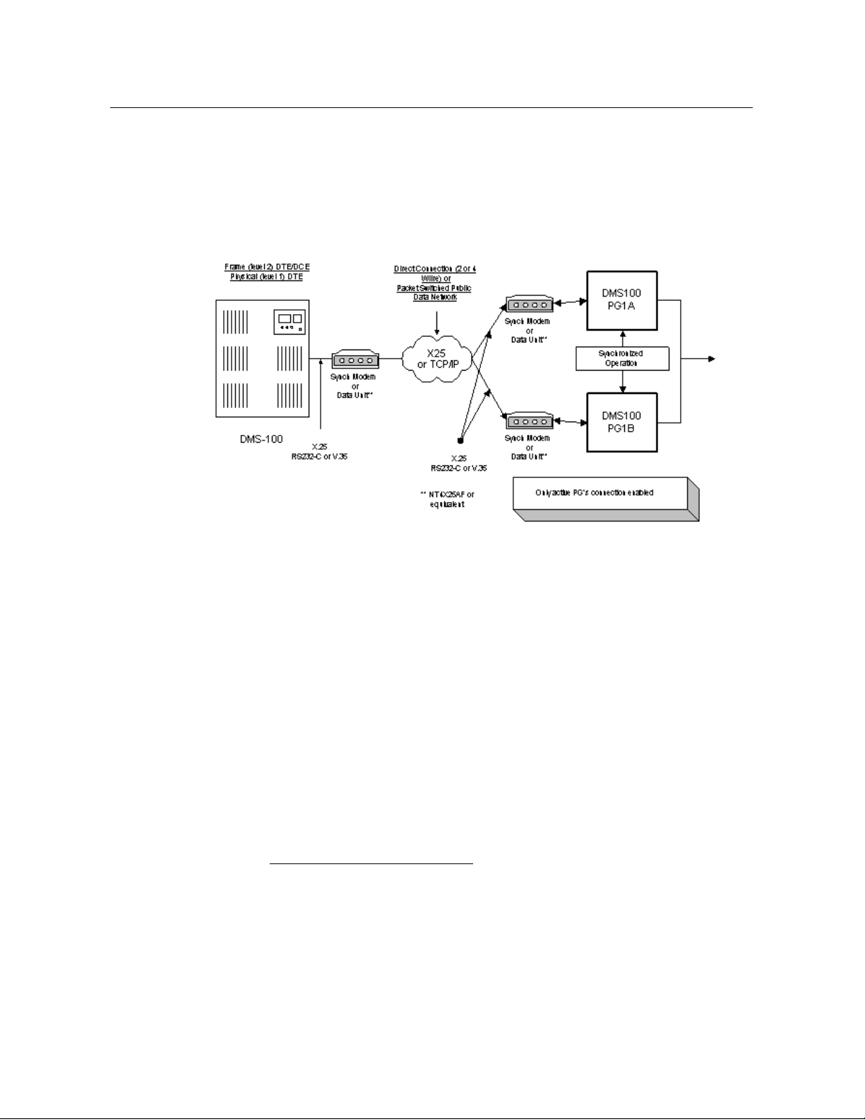
1.1. DMS100 PG with CompuCALL Link
The DMS100 PG can run in simplex or duplex configurations. In a duplex
configuration, only one side of the PG will maintain CompuCALLF1F
X.25 Link or a TCP/IP connection at any given time.
Figure 1: CompuCALL Interface with DMS100
The DMS100 PG can invoke the ANSWER, RELEASE, HOLD and
UNHOLD of incoming calls to ACD agent, Centrex line or Residential
line. The CompuCALLF2F messages, DV-ANSWER-CALL, DVRELEASE-CALL, DV-HOLD-CALL and DV-UNHOLD-CALL allow
the DMS-100 PG to provide third-party call control service to third-party
voice application vendors.
CallsF3F like Three-way Call (3WC) or Call Transfer (CXR) call event
message, DV-Consult-Originated-U, DV-Call-Conferenced-U and DVCall-Transferred that are sent from the DMS-100 switch to allow the
DMS-100 PG to build call conference/transfer model, when the 3WC or
CXR key option, is data-filled on the telephone set.
Note: Since the CompuCALL interface in the release 08.01 does not
support Call Conference (CNF) key, it is required that CNF key not
be data-filled on the telephone set.
1
CompuCALL is a protocol that provides a data communications channel
between a computer and a switch that allows an operating company to provide
coordinated switch-based services, to applications residing on a customer's host
computer in a cost efficient manner.
2
These messages are supported with the CompuCALL interface from release
07.01 onwards.
3
These messages are supported with CompuCALL software release 08.01
onwards.
Page 13
DMS100 PG with CompuCALL Link 13
PLC
NA100
APC100
PCL
LEC
CDN
ABSK
ABSL
ABSM
CCM02
02
02
CCM03
03
03
CCM04
04
04
04
00
03
CCM05
05
05
02
04
CCM06
06
Note 1
03
01
05
CCM07
07
04 06
CCM08
08 05
02
07
CCM09
09 06
TBD
08/09
CCM10
10 07/08
TBD
10/11
CCM11
11 TBD
TBD
TBD
PLC
EUR100
MSL100
DMS500
PCL
EUR
MSLIVD
LLT
LLDB
CCM02
CCM03 03
CCM04
03
04
04/05
04/05
CCM05
04
05
Configure the ServiceVersion parameter in the DMS-100 PG session
configuration to receive a correct stream of CompuCALL messages. The
DMS-100 PG uses the configured parameter to pass on to the
ServiceVersion field in the DV-Application-Log-On message, which will
be sent during the application logged on session. The ServiceVersion value
uniquely identifies the stream of messages which are corresponding to the
appropriate CompuCALL software release.
For example, the ServiceVersion value for the stream of Switch Computer
Application Interface (SCAI) of the CompuCALL release 08.01 is:
SCAI10.
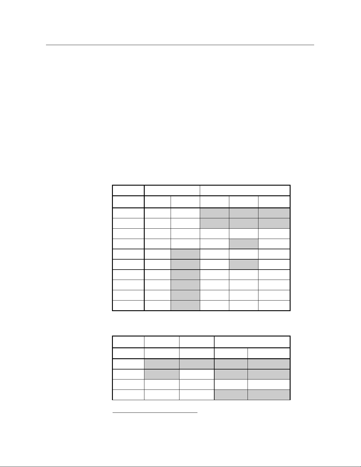
1.1.1. CCM Matrix Support
Since the DMS-100 PG supports up to CCM10, use the following CCM
(Common CM) Matrix tables to find out which PLC and PCL the DMS100 PG supports.
Table 1: CCM Matrix_1
F1F
Table 2: CCM Matrix_2
1
A CCM is one of several types of Development Release Unit (DRU).
Page 14
14 Overview
CCM06
05
06
CCM07
06 07
06
CCM08 07
08
TBD
CCM09
08
08
09
TBD
CCM10
09
09
10
TBD
CCM11
10
10
11
TBD
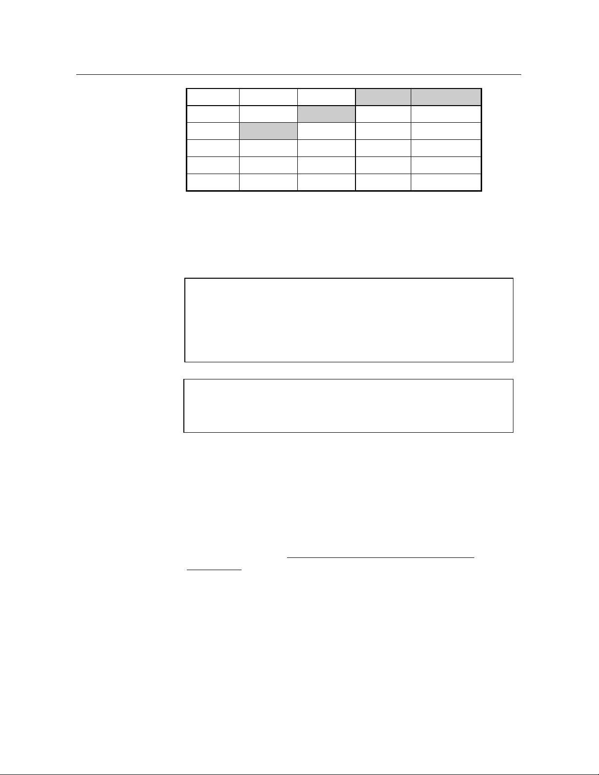
Note: 1. Beginning CCM06 CDN & LEC were combined into a single
PCL (Product CM Load) stream.
2. Shaded area indicates that the DRU was not implemented for the
PCL.
Examples of PCL (Product CM Load) include:
CDN is Canada
LEC is DMS-100/200
MSLDIVD is MS-100 Commercial Market
ABSK is Japan IDC
ABSL is Japan NTT
ABSM is Others (Australia, Philippines, CALA)
LLT is DMS-500 Local/Long Distance/TOPS
LLDB is DMS-500 Local/Long Distance
Examples of PLC (Product Line Center) include:
EUR is Europe
NA is North America
MSL is SL-100
APC is Asian Pacific
DMS -500
1.2. CompuCALL Interface Requirements and Limitations
For optimized performance and utilization of the Cisco Enterprise
Computer telephony Integration (CTI) solution, the CompuCALL software
release 09.01 or above has to been loaded on the DMS-100 Switch.
The CompuCALL software load NA09 allows the DMS100 PIM to know
the Agent Skill Group reassignment when the Call Center supervisor reassigns an Agent from one Skill Group to another Skill Group.
Please see the Section, “Monitoring Agent Skill Group Assignment
Change”UH
monitor Agent Skill Group assignment change.
Note: Install the appropriate patch for CompuCALL software load NA09
1.2.1. CompuCALL Interface Limitations
Any CompuCALL software load below NA09 on the DMS100 Switch
does not support the DMS100 PIM ability to monitor Agent Skill Group
assignment change.
, for detailed information about the ability of the DMS100 to
or above on the DMS100 Switch to enable it to work properly with
DMS100 PG.
Page 15

Nortel DMS100 Switch Limitations 15
1.3. Nortel DMS100 Switch Limitations
If the PIM receives an out of order sequence message in the LOGOUT or
NOT_READY state, it is due to the inter-working of the DMS100 PIM
and the Nortel DMS100 switch.
Page 16

Page 17

17
2. Unified ICM Configuration
In order to properly configure and maintain the database, you need to
understand the relationship between the DMS100 switch database objects
and the database objects.
This chapter describes how objects map between the DMS100 ACD and
the Unified ICM. It also provides DMS100 switch-specific information
that may assist you in configuring the PG through the Configuration
Manager tools.
For detailed information on the Unified ICM Configuration Manager
tools’ user interface, see the Configuration Guide for Cisco Unified
ICM/Contact Center Enterprise and Hosted.
Page 18

18 Unified ICM Configuration
2.1. Configuring the DMS-100 ACD
To best understand the configuration of the DMS-100 ACD, begin with the
DMS-100 documentation shipped with your switch. The information
provided here is meant to supplement and not to replace the Nortel DMS100 documentation.
2.1.1. Configuring the Peripheral
The “Configure a PG” option in Configure ICM automatically creates a
peripheral object with the appropriate defaults for a DMS-100 peripheral.
If desired, these values can be modified through the peripheral screen in
Configure ICM.
The “Available Holdoff Delay” setting will be used by all Skill Groups for
this peripheral that do not explicitly specify a value for the “Available
Holdoff Delay” at the Skill Group level.
2.1.2. Configuring the Peripheral Targets
A peripheral target should be configured for each combination of Network
Trunk Group and DNIS that can receive ACD calls. Peripheral targets
must also be configured for translation routing
2.1.3. Attributing Calls to Unified ICM Routes
For route statistics, the PG attributes calls to the routes by looking for a
peripheral target that matches the Trunk Group and DNIS for the call and
using the route associated with that peripheral target. If no matching
peripheral target is found, then the call is attributed to the default route for
the peripheral (if one is configured).
2.2. Services
See the Services the Unified ICM services.
2.3. Skill Groups
See the Skill Groups configure Unified ICM Skill Groups.
The “Available Holdoff Delay” should be set to the value of the Variable
WrapUp for this ACD DN. This value is left as “Use Peripheral Default,”
then the default value configured for this peripheral will be used.
The DMS-100 switch does not strictly associate call WrapUp time with
individual calls. The DMS-100 tracks the total time spent by an Agent in
the NotReady state. The Average Work Time is calculated as (ACD
TalkTime + NotReady Time) / Calls Answered.
The Agent can enter the NotReady state at any time and begin
accumulating NotReady Time.
section X2.12.5X, for specifics about when to configure
section X2.12.7X, for a discussion of when to
Page 19

Labels 19
There are two methods Agents can associate WrapUp time with individual
calls:
• When the Agent issues the NotReady feature (manually or via
CompuCALL SetFeature) while active on a call. When the call is
completed, the Agent will be placed in the NotReady state.
• Through Variable WrapUp feature available on the DMS-100. The
Unified ICM does not receive an indication that the Agent is in the
NotReady State when the call terminates.
The PIM uses the AvailableHoldoffDelay setting to determine when to
place the Agent in the Ready State once the call is released. It is
applicable to all calls for the Peripheral or Skill Group. The
AvailableHoldoffDelay timer on the DMS100 PG must match the Variable
WrapUp for the ACD DN that the agents belong to. If the timer
configuration is incorrect, an agent state mismatch occurs between the
DMS100 PG and the DMS100 ACD.
2.4. Configuring the Agents
See the Agent
agents in the Unified ICM.
section X2.12.8X, for a discussion of configuring DMS-100
2.5. Dialed Numbers
See the Dialed Numbers configuring dialed numbers for DMS-100 Peripherals in the Unified ICM.
2.6. Labels
Each destination to which Post Routed calls should be routed should have
a label configured with the label string set to the destination as it would be
dialed from a phone set. For example, labels may be configured to route
calls to a Primary ACD DN, Supplementary ACD DN, or Secondary DN.
You can assign dynamic call-related information, hostCallData in the
Unified ICM label configuration. The DMS-100 PG will send
hostCallData to the switch; the switch saves the hostCallData, and sends it
to another host application in any subsequent switch-host messages. A
HostCallData is an octet string of a maximum 10 bytes.
The “Label” filed in Label Configuration dialog under the Configure
ICM application has the following two formats:
section X2.12.10X, for a discussion of
Page 20

20 Unified ICM Configuration
Label Format
Example
Meaning
DnnnHnnn
D9136243685H333
DialedDigits for
redirectDestination is 9136245686.
HostcallData is 333.
DN
9136245686
DialedDigits for
redirectDestination is 9136245686.
HostcallData is of null content.
Session
Parameter
Example
Description
ApplicationID
1
Integer that identifies the software as
the application that is initiating the
logon request
BusinessGroupID
6
Integer that identifies your company.
Your Interexchange Carrier defines
this ID
NetworkNodeID
40
Integer identifier that specifies the
switch that the software will use to
communicate. This is the switch the
host computer connects to via the
CompuCALL link. Your Interexchange
Carrier defines this ID
P a ss w or d
BLAZER
Is provided by the system
administrator for security purposes.
The password corresponds to the
BusinessGroupID
ServiceID
1
Integer that identifies the application
context to be set for the session (i.e., a
service profile containing Application
Service Options or subsets, as defined
by your Interexchange Carrier)
ServiceVersion
10 for
SCAI10
Integer that specifies the application
level or the signaling version that the
host application is using
Table 3: DMS-100 PG Label Format
2.7. PG CompuCALL Session Configuration
This section describes how the PG must be configured through the Setup
program to logon DMS-100 PG on DMS-100 Switch as a host application.
Table 4: CompuCALL Session Parameters
Page 21

Peripheral Monitor Configuration of ACD Positions 21
X.25 Link Parameter
Example
Description
X25 Port
1
Integer identifier for the X25
card install on the local
computer
X25 User Data
0 0 0 0
Four octets of data (each octet
ranging from 0 to 255,
expressed in hexadecimal).
These data are provided by the
Interexchange Carrier as the
PROTOCOL subfield. Each
octet is separated by a white
space
X25 Local Address
02402027
Is X.25 DTE address of the
local computer provided by
the system administrator
X25 Remote Address
00000555
X.25 DTE address of the
remote switch provided by the
system administrator
If you configure the PG to connect at SCAI-11F1F, irrespective of the
SCAI level set on the DMS100 switch, the PG will function with the
switch.
There is no specific configuration required on the DMS100 switch to
ensure that PG connects with a lower SCAI level set at the PG. The
DMS100 switch handles the configuration transparently and autonegotiates the SCAI version (ServiceVersion) with the PG.
2.8. PG CompuCALL X.25 Link Configuration
This section describes how the PG must be configured through the Setup
program to talk to the CompuCALL X.25 Link.
Table 5: CompuCALL Link Parameters
2.9. Peripheral Monitor Configuration of ACD Positions
To be able to monitor the CompuCALL event messages, you must
configure all of your Primary ACD or Secondary DN positions in the
peripheral monitor table. The DMS-100 Peripheral Gateway will perform a
DV_DN_ASSOCIATION for each of the Primary ACD DNs configured
in the Peripheral Monitor TableF2F. If the DMS-100 PG specifies a
Primary ACD DN to be associated with the current session, the DMS-100
1
The PG continues to support SCAI-11 and no new features that are part of SCAI
versions higher than SCAI-11 are supported by the PG.
2
All the devices associated in the call need to be monitored by the DMS100 PG,
in order to avoid any missing events being missed from the DMS100 to the
system. These events could impact system functionalities like call routing,
reporting etc.
Page 22

22 Unified ICM Configuration
PG is informed by the switch of all call and Agent events to that ACD
Group. Furthermore, if the ACD Group has one or more Supplementary
ACD-DNs associated with it, then all these Supplementary ACD DNs are
automatically associated with the current session. If the DMS-100 PG
specifies a Secondary DN to be associated with the current session, the
DMS-100 PG is informed by the switch of all coordinated voice and data
delivery events to that Centrex or Residential line.
You may specify the configured CompuCALL session number for a
Primary ACD DN or Secondary DN in the Unified ICM peripheral
monitor table. The configured CompuCALL session number indicates DVDN-ASSOCIATE OPERATION for the Primary ACD DN, or Secondary
DN in the “Extension” field will be performed by the CompuCALL
session n. The assignment of the configured CompuCALL session number
is optional. If you fail to specify session number n for a Primary ACD DN
or Secondary DN, the DMS-100 PG will evenly distribute DNs over the
configured the CompuCALL sessions
You can specify whether a Primary ACD DN is CDN in the peripheral
monitor table. The DMS-100 PG uses this information to call DV-SetCDN-State during the initialization procedure.
Since an Agent device can be assigned to two lines, ACD and Secondary
lines, you need to provide the mapping relationship between the Secondary
DN, agent DN, and Agent positionID CDN in the peripheral monitor table.
If an Agent device has only one ACD line, you need to mark the
“Extension” field with a non-digital letter (e.g., &), and specify the address
mapping relationship between the Agent DN and the Agent PositionID in
the corresponding “Param String” field in the peripheral monitor table.
Page 23

Peripheral Monitor Configuration of ACD Positions 23
The peripheral monitor screens for a Primary ACD DN and a Secondary
DN from Configure ICM are shown below.
Figure 2: Peripheral Monitor Configuration Window
Page 24

24 Unified ICM Configuration
Extension
Format
Example
Meaning
Primary ACD DN
9136243685
Dial Plan Directory Number of the
Primary ACD -DN assigned to the
ACD Group.
Secondary DN
9136245686
Dial Plan Directory Number of the
Secondary DN assigned to the
Centrex or Residential line.
Non-digit character
&
Any ASCII character other than digit
character ( 0 – 9 ) indicates it is
either a Primary ACD-DN or a
Secondary DN.
Figure 3: Peripheral Monitor Configuration with Parameter
String
The “Extension” field is of your Primary ACD DN, Secondary DN, or
non-digit character.
Table 6: Extension Formats
The “Param String” field allows several different types of input that can be
used to specify the CDN, CompuCALL session number, and the address
mapping relationship between the Agent DN and the Agent positionID
(see below).
Page 25

CompuCALL Server 25
Param String
Format
Example
Meaning
<SN n>
<SN 1>
The configured CompuCALL
sessions n to be associated to the
Primary ACD DN, or Secondary
DN in the “Extension” field
<CDN>
<CDN>
Indicates the Primary ACD DN in
the “Extension” filed is a CDN
<DN dn> <ID
posID>
<DN 9136243686>
<ID 3686>
Indicates that an Agent device has
an ACD line with the Agent DN
dn, and the agent PositionID
posID.
The Type field should be set to “ACD DN.”
Several tags in the “Param String” field can be used to specify the CDN,
CompuCALL session number, and the address mapping relationship
between the Agent DN and the Agent positionID.
Table 7: Param String Formats
2.9.1. Transferring Calls to Non-monitored Devices
If queued calls are transferred to a party that is not a CompuCALL
monitored device, the DMS100 does not send a DV-CALL-OFFERED-U,
DV-CALL-ANSWERED-U message to the system. Without this message
from the DMS100, the PIM does not know when the consulted call got
offered and answered.
Therefore, when the conference controller releases the call, the system also
thinks that the consulted call is still in the QUEUED state regardless of
whether the call has actually been transferred and answered.
2.10. CompuCALL Server
The CompuCALL Server (CCS) allows a new or existing third-party
application to share the DMS-100 CompuCALL interface with the
software for the purpose of monitoring and/or controlling Agents and calls
for the same Agent positions that the software is monitoring and/or
controlling. Although both the third-party application and software can
monitor, only one of them should attempt to control the same Agents or
calls.
The CCS is a process typically running on the PG, although it may run on
a separate host accessible to the PG via the network. All configurations for
the CCS are done during setup—no special CCS configuration is needed in
configuring the system. The DMS-100 PIM must be configured during its
setup to connect to CCS rather than directly to the DMS-100. The thirdparty application must physically connect to CCS (via X.25 or TCP), but
otherwise no change needs be made – to all appearance, CCS will be the
DMS-100. (TCP support is included in ICM release 3.0 and later.)
Page 26

26 Unified ICM Configuration
2.10.1. Simple Case
In the simplest case, only one CompuCALL Session is configured in the
DMS PIM, in the third-party application, in CCS, and at the DMS-100 (see
diagram below).In this simple case, exactly one connection will be used:
1. Between CCS and the third-party application (X.25 or TCP)
2. Between CCS and the DMS PIM (Cisco proprietary EMT interface)
3. Between CCS and the DMS-100 (X.25 or
TCP).
Figure 4: CompuCALL Session: Simple Case
In this simple case, which will likely also be the typical case, the CCS
setup requires the configuration of the following:
1. One ACD Link of type X.25 or TCP (from CCS to the DMS-100)
2. One application Link of type X.25 or TCP (from CCS to the third-
party application)
3. One Session – which includes which ACD Links are used by the
Session (from item 1 above)
4. Two applications for the Session:
• One for the third-party application -- which includes which
application Links are used by the third-party application (from
item 2 above)
• One for the DMS PIM
Once the CCS is configured and running, the third-party application and
the DMS PIM can execute the following steps (just as they would if
connected directly to the DMS-100):
1. Create a connection (either X.25 SVC or TCP for the application,
EMT for the PIM)
2. Send a Session Logon message on the connection
3. DN Associate those Agents or Agent groups to be monitored
When the PIM or the third-party application logon, whichever is first, CCS
will establish a connection to the DMS-100 and send the logon message to
establish a CompuCALL Session with the DMS-100. This Session will be
shared by both the third-party application and the DMS PIM, once both
have logged on. The DMS-100 Session will be maintained as long as
either the third-party application or the DMS PIM remains logged on to the
CCS. (Generally, either the third-party application or the PIM can log on
first; however, the third-party application and the PIM can be assigned a
Page 27

CompuCALL Server 27
priority, and an option exists to block any logon until the highest priority
application [or PIM] has logged on, and to force the logout of the lower
priority application [or PIM] when the highest priority application [or
PIM] logs out).
Once the DMS-100 Session is established, the PIM and the third-party
application may send DN Association messages. CCS keeps track of
which DNs have been associated so only new associations are sent to the
DMS-100.
At this point, CCS knows which DNs have been associated by the thirdparty application and the PIM; and as monitor messages are sent by the
DMS-100, CCS forwards them to either or both, depending on which has
associated the DN for the message. CCS also keeps track of the InvokeIDs
for any control messages or queries sent by the third-party application or
the PIM, so that the response will be sent back to the right place.
2.10.2. Complex Cases
A few complexities of various kinds can be introduced to the simple case:
1. More than one X.25 Link can be configured to the ACD or to the
third-party application, and a single CompuCALL Session can span
those X.25 Links.
• The DMS-100 allows multiple connections and logons for the
same Session over multiple X.25 Links, both for increased
bandwidth and redundancy purposes. The DMS-100 applies DN
Associations done by any of the connections to the Session as a
whole. Monitor messages are split across all of the connections by
call (all messages for the same call use the same connection), so if
there are two connections, each receives approximately half of all
the messages.
• This introduces the concept of a link group. In the simple case (see
6.1), messages sent from the DMS-100 to CCS are forwarded on
one or both of the connections to the third-party application or the
DMS PIM. The three connections are related, in that they share the
same messages. These three connections are called a link group.
When multiple X.25 Links are configured to the DMS-100 for the
same Session, multiple link groups are created in CCS. (See
diagram below.) Each link group sees a different set of messages.
There is no fixed mapping at configuration time as to which Link
from the DMS-100 corresponds to which connection to the thirdparty application or PIM, but the total number must match (or
must be greater than or equal to the desired number of active
links—the desired number of active links for a third-party
application is configurable in the CCS setup). For each X.25 Link
to the DMS-100, an X.25 Link must be configured to the thirdparty application, and an EMT connection must be configured in
the DMS PIM. (Actually, multiple connections can be established
over a single high-speed X.25 Link from the third-party
Page 28

28 Unified ICM Configuration
application if desired. Each such connection would use a different
X.25 Link to the DMS-100).
Figure 5: CompuCALL Session: Complex Case
2. More than one third-party application can be configured for a Session.
Each must have a unique ProxyApplicationID configured in CCS to
differentiate them. The ServiceID in the CompuCALL session has to
be configured in the third-party application or DMS-100 PIM. When
they make connections to the CCS, the CCS checks the value of
ServerID in the DV_APPL_LOGON message to identify the
application by comparing the ServiceID with ProxyApplicationID.
There is no need to configure the ProxyApplicationID for a primary
CompuCALL application (third-party application or DMS-100 PIM).
Note:
3. Third-party application connections to the CCS, and CCS connections
to the DMS-100 can be any combination of X.25 and TCP. In other
words, the CCS connection to the DMS-100 can be X.25 at the same
time third-party application #1 uses TCP, while third-party application
#2 uses X.25. However, the number of connections must match for
each Session (as described in 1 above). The DMS-100 switch permits
only one TCP connection for the same Session.
Although CompuCALL protocol supports a multiple sessions
per Compucall Link, neither the PIM nor the CCSG supports
this configuration.
Page 29

CompuCALL Server 29
Option
Name
Option Description
Value
Default
Min
Max
Accept Any
Session
Not implemented currently.
Accept Sessions which are
accepted by the DMS-100 even if
not configured in CCS.
Yes/No
Displayed
ServerID
Not used.
0 0 0
2.10.3. Setup Details
Figure 6: CompuCALL Server Setup
There are four CompuCALL Servers that may be configured on a single
host. Each must use a unique EMT and TCP Socket address. No two
CompuCALL Servers can share the same X.25 Port for applications. Two
CompuCALL Servers can share the same X.25 Port for access to the ACD
(and at most one can ALSO use this X.25 port for applications). Sharing
one X.25 Link by two applications is not advised unless connecting to the
ACD via an X.25 Packet Switch, and via a high-speed link.
Table 8: CompuCALL Server Setup Options
Page 30

30 Unified ICM Configuration
EMT Port
CCS EMT Port Number that is
used by DMS PIM to
communicate to CCS.
CompuCALL Server EMT port
assignments follow the following
convention:
Port numbers are of the
form 4SFFF where
S = 0-4
corresponds to CCS1 –
CCS5 on side A (only CCS1CCS4 currently supported)
= 5-9
corresponds to CCS1 –
CCS5 on side B (only C C S 1 CCS4 currently supported)
FFF = customer number * 40 +
029
40029
49769
Displayed
TCP Port
CCS TCP Port Number that is
used by third-party application
and DMS PIM to communicate
to CCS.
CompuCALL Server TCP port
assignments follow the following
convention:
Port numbers are of the
form 4SFFF where
S = 0-4
corresponds to CCS1 –
CCS5 on side A (only CCS1CCS4 currently supported)
= 5-9
corresponds to CCS1 –
CCS5 on side B (only CCS1CCS4 currently supported)
FFF = customer number * 40 +
030
40030
49770
Displayed
ACD Links
See XTable 9: ACD Link Setup OptionsX.
Application
X25 Links
See XTable 11: Application Link Setup OptionsX.
CompuCALL
Sessions
It is recommended that ACD Links and Application Links are
set up prior to setting up CompuCALL Sessions.
Page 31

CompuCALL Server 31
Figure 7: ACD Link Setup
Page 32

32 Unified ICM Configuration
Option
Name
Option Description
Value
Default
Min
Max
Link ID
ID used in error/status messages
which reference the link. When
default is used (recommended)
this corresponds to labels used
in the “Session Configuration”
dialog box’s “ACD Link IDs”
check boxes.
1 8 Displayed
Link Name
Link name used in error/status
messages which reference the
link.
Up to 40
ASCII
characters.
None
X25 Port
Number
EICON X.25 Port number.
1
8
None
X25 Local
Address
Not used.
Up to 14
decimal
digits.
None
TCP Port
Number
DMS-100 switch TCP wellknown port number
2500.
2500
TCP Host
Name
DMS-100 switch Host Name
N/A
None
Table 9: A C D Link Setup Options
Page 33

CompuCALL Server 33
Option Name
Option Description
Value
Default
Min
Max
CompuCALL
Logon Parameters
See XTable 10: Session Object Setup OptionsX.
User Data
X.25 SVC call
parameter – as
configured at DMS-
100.
Four octets (each
0-255) separated
by spaces.
None
Remote Addr
X.25 SVC call
parameter –
destination DTE
address as configured
at DMS-100.
Decimal digits
None
Figure 8: Session Object Setup
Table 10: Session Object Setup Options
Page 34

34 Unified ICM Configuration
App IDs for
Unknown Message
Select those
applications that will
receive “unknown
messages”. Unknown
messages are those
messages that may be
introduced in future
versions of the
CompuCALL
interface. The
application ID as it
appears in the
“CompuCALL
Applications” list box
of the “Session
Configuration” dialog
box.
Yes/No
No
Delay Activation
Not implemented
currently.
0
255
No
Delay Logon
Not implemented
currently.
0
255
0
Disable Session
No lower priority
applications allowed
to logon, or to remain
logged on, unless
highest priority
configured application
is logged on.
Yes/No
No
Force Failover
Not implemented
currently.
Enable/disable the
system’s ability to
force Host application
failover.
Yes/No
No
PassiveFailover
Not implemented
currently.
Enable/disable duplex
CCS Passive Failover.
Yes/No
No
Page 35

CompuCALL Server 35
ACD Link IDs
Select those ACD
Links that will be used
by this Session. The
ID is as it appears in
the “ACD Links” list
box of the
“CompuCALL Server
Properties” dialog box.
This is the same as the
“ACD Link ID” of the
ACD Link
Configuration dialog
box UONLY IF
U
the
default value is used.
CompuCALL
Applications
See XTable 12: Application Configuration OptionsX.
Option
Name
Option Description
Value
Default
Min
Max
X25 Link ID
ID used in error/status
messages which reference the
link. When default is used
(recommended) this
corresponds to labels used in
the “Application
Configuration” dialog box’s
“X25 Link Ids” check boxes.
1 8 Displayed.
X25 Link
Name
Name used in all error/status
messages referencing the link.
ASCII text (up
to 40 chars)
0
Figure 9: Application X.25 Link Setup
Table 11: Application Link Setup Options
Page 36

36 Unified ICM Configuration
X25 Port
EICON X.25 port number.
1 8 1
X25 Local
Address
X.25 DTE address assigned to
the X.25 Link. Used only for
documentation purposes when
X.25 Link is attached to X.25
Packet switch.
Up to 14
decimal digits.
Option Name
Option Description
Value
Default
Min
Max
Application Name
Name of application for
documentation purposes
and as it will appear in
error/status messages
ASCII Text
none
Desired Link Count
Desired number of
active links. The desired
number for the Session
is the desired number
for the active
application with the
highest priority.
1 8 1
Minimum Link Count
Minimum number of
active links. In future
duplex CCS
configurations, this
value defines a
threshold for failover to
duplex CCS.
1 8 1
Figure 10: Application Configuration
Table 12: Application Configuration Options
Page 37

Support for Walk-Away Reason Codes 37
Priority
Application Priority
(lower number is
higher priority).
0
255
0
Proxy Application ID
Application ID of thirdparty application and
DMS-100 PIM. It
equals to the ServerID
in the CompuCALL
application logon
message.
0
255
0
Walk-Away Codes
Definition
Include in Callhandle time
000
Default (No code)
X
105
Personal Need
115
Break
130
30 min. lunch
145
45 min. lunch
160
60 min. lunch
190
Approved Leave
201
Training
202
Administration
203
Meeting
204
Supervisor
301
Wr ap -up
X
302
Claim Follow-up
2.11. Support for Walk-Away Reason Codes
When an ACD Agent hits the NotReady button on an Agent device, the
NotReady light will be blinking to indicate that the Agent can enter a
walk-away code. If the system timer expires, the DMS100 switch sends a
DV-Agent-NotReady-U message without walk-away code.
Some Agent activities indicated by the walk-away codes need to be
included into the Average Handled Time computation. The approach is
provided to allow use to configure database to support the feature.
XTable 13X is one example of walk-away codes. The system
configuration is also shown how the walk-away codes marked with an "X"
to be included in call-handle time.
Table 13: Example of Walk-Away Codes
Page 38

38 Unified ICM Configuration
303
Special Claim Follow-up
304
Down Mode
401
Exceptions
402
Determinations
403
Special Projects
501
Child Support Intercept
502
Teletypwriter
503
Interpreting
-1
Not defined. (wrong code used)
2.12. Object Mapping
It is very important to understand the Call Distribution Mode for the
DMS100 switch in order to configure the PeripheralTarget, Route and
Service and their association.
The Peripheral Gateway performs a DV_DN_ASSOCIATION for each of
the Primary ACD DNs configured in the Unified ICM Peripheral Monitor
Table. If the PIM specifies a Primary ACD DN to be associated with the
current session, the host application is informed by the switch of all calls
to that ACD Group. Furthermore, if the ACD Group has one or more
Supplementary ACD-DNs associated with it, then all of the Supplementary
ACD DNs are automatically associated with the current session.
2.12.1. Peripheral
The Peripheral corresponds to the collection of CompuCALL sessions
associated with a BusinessGroupID.
2.12.2. Peripheral Targets and Routes
Peripheral Targets are the means that the software maps/directs calls to
Services, Skill Groups or Agents. A Peripheral Target is specified by a
Network Trunk Group and a DNIS pair. Each Peripheral Target is
associated with a single Route. A Route is associated with a Target Type
(Service, Skill Group, Agent, Translation Route). For accounting purposes,
each Route is associated with a Service. It is this mapping that will allow
the Peripheral Gateway to define the CallType (Service) when a new call
arrives on the DMS-100.
The DNIS configured in the Peripheral Targets must correspond to the
Primary or Supplementary ACD DN defined on the DMS-100. The DNIS
configured in the Peripheral Targets for the Primary ACD DN is the dialed
number of Primary ACD DN, and for the Supplementary ACD DN, it is
the dialed number of Supplementary ACD DN.
Page 39

Object Mapping 39
The configuration of Peripheral Targets for calls associated with
Supplementary DNs is required to define the proper call type when the call
is offered to the DMS-100.
2.12.3. Trunk Groups
The CTI Links utilized by the DMS-100 Peripheral Gateway offer no
Trunk level statistics to the customer. Trunk configurations on the DMS100 are treated as a POOL of inbound/outbound resources that are
accessible by all Call Types.
2.12.4. Trunks
No trunk information is provided by the CompuCALL Interface. As a
result, Trunks need not be entered in the Unified ICM configuration.
2.12.5. Services
The Cisco Service abstraction is defined as “a type of caller need that the
peripheral handles” (i.e., Quotes, Sales, Brokerage). The Unified ICM will
choose a Service based on the current Routing Script that is scheduled for
the dialed number being requested. The Router responds to the Routing
Client with the Label, which is specific to the Routing Client Type, which
defines how the call is to be treated. For Network Routing Clients, the Call
is directed to an ACD on a particular Trunk Group with a specific DNIS
and/or ANI. For ACD Routing Clients, the Label defines a target on the
ACD that performs specific call treatment. This could include on or off
switch processing of the call.
The DMS-100 ACD will follow either of these call delivery models. When
the call arrives to the ACD, it is offered to the ACD Group associated with
the Primary/Supplementary ACD-DN of the call. In both the DMS-100
and Unified ICM models, Agent/Skill Groups may be associated with one
or more services.
A Service Object has to be configured for each Primary ACD-DN and
each Supplementary ACD-DN.
The “Extension” configured in the Service Object must correspond to the
Primary or Supplementary ACD DN defined on the DMS-100. The
“Extension” configured in the Peripheral Targets for the Primary ACD DN
is the dialed number of Primary ACD DN; and for the Supplementary
ACD DN, it is the dialed number of Supplementary ACD DN.
The configuration of Service Objects for calls associated with
Supplementary DNs are required to define the proper call type when the
call is offered to the DMS-100.
Each Service Object has to be associated with a PeripheralTarget and
Route object in the system configuration.
Page 40

40 Unified ICM Configuration
Unified ICM
Service
DMS-100 Service
Description
SkillTargetID
none
Unified ICM
SkillTargetID
defined by Cisco
PeripheralNumber
Last four to six digits of Primary
ACD-DN or the Supplementary
ACD-DN**
Last four to six
digits of Dial Plan
Directory Number
of the Primary or
Supplementary
ACD-DN
assigned to the
ACD Group.
Extension
Dial Plan Directory Number of
Prim a r y A C D -DN if configuring for
a Primary ACD-DN or Dial Plan
Directory Number of Supplementary
ACD-DN if configuring for a
Supplementary ACD-DN
Dial Plan
Directory Number
of the Primary or
Supplementary
ACD-DN
assigned to the
ACD Group.
The following table defines the Service Object member mapping used
when configuring a Service in the software.
Table 14: Unified ICM to DMS-100 Service Mapping
2.12.6. Default Peripheral Route
Note: In some customer configurations, the Supplementary ACD-DN
could be associated with the service of the Primary ACD-DN.
** The selection of last four to six digits of the Primary ACD-DN or the
Supplementary ACD-DN has to be unique within “Service All” in the
Configure ICM dialog.
If the PG is informed of a call for which there is no Peripheral
Configuration (PeripheralTarget/Route and/or Service not configured), the
call is not tracked. This is likely to occur when the configuration does not
match the configuration defined on the DMS-100. An example of this
would be when a customer is not routing all call types handled by the
switch, but the CTI Link provides events on all Call Types.
To allow some type of monitoring of calls that have no definitive
Route/Service mapping, the software provides the Peripheral Default
Route. The Peripheral Default Route provides a place holder to gather
statistics on calls that are monitored by the CompuCALL Link, which do
not map to the configuration. The software will gather Route/Service
statistics associated with these unknown calls along with their Termination
Call Details.
Page 41

Object Mapping 41
Unified ICM Skill
Group
DMS-100 Skill Group
Description
SkillTargetID
None
Unified ICM SkillTargetID
defined by Cisco
PeripheralNumber
Last four to six digits of
Prima r y A C D -DN of the
ACD Group
Last four to six digits of
Dial Plan Directory
Number of the Primary
ACD-DN assigned to the
ACD Group.
Extension
Primary ACD -DN of the
ACD Group
Dial Plan Directory
Number of the Primary
ACD-DN assigned to the
ACD Group.
Peripheral Name
ACD Group Name
Name associated with an
ACD DN of an ACD
Group.
From the Termination Call Details of the call associated with the
Peripheral Default Route, the customer can track down the unknown call
types. The Termination Call Detail will provide the ACD-DN associated
with the call. The Customer can then update the configuration to include
the non-configured call types.
2.12.7. Skill Groups
The Cisco Skill Group abstraction is defined as “a collection of Agents
that share a common set of skills.” The DMS-100 ACD Groups are
consistent with the Cisco definition of a Skill Group. The Cisco Skill
Group contains the following fields: a SkillTargetID, a Peripheral Number,
a Peripheral Name and an Extension Number. The SkillTargetID is
utilized by the Router to target Skill Groups in the Scripting Language.
The following table defines the SkillGroup/DMS-100 ACD Group Object
member mapping used when configuring a Skill Group in the software.
Table 15: Unified ICM to DMS-100 Skill Group Mapping
** The selection of last four to six digits of Primary ACD-DN has
to be unique within “Skill_Group All” in the Configure
ICM dialog.
On the DMS-100, an ACD Group can be assigned one Primary ACD-DN
and up to 16 Supplementary ACD-DNs. Calls arriving with the Primary
ACD-DN are queued to the ACD Group at priority 0 (Highest priority).
The Supplementary ACD-DNs assigned to the ACD Groups are given a
priority in the range of 0-3 where 3 is the lowest priority. Calls are
answered by Agents assigned to the ACD Group based on the arrival and
priority of the call. A call waiting longer in the Priority 1 queue will not be
serviced if a call is pending in the Priority 0 queue. Calls offered to an
ACD Group that have available Agents are assigned to the MOST IDLE
Agent.
Page 42

42 Unified ICM Configuration
Unified ICM
Ag ent
DMS-100 Agent
Description
SkillTargetID
None
Unified ICM SkillTargetID defined
by C i s c o
PeripheralNumber
PositionID
DMS-100 Identifier for the position
the agent logged onto. The Position
Identifier is assigned to the ACD set
where an Agent login occurs.
Extension
PositionID
Same.
FirstName
Not available.
First Name of Agent.
LastName
Not available
Last Name of Agent.
2.12.8. Ag e nt
The Agent Object is made up of the following fields: a SkillTargetID, a
Peripheral Number, an Extension Number, a State, a list of active Skill
Group assignments, and a First and Last Name. From the Unified IC M
perspective, the Agent Object is uniquely identified by the SkillTargetID.
The SkillTargetID allows for the Router to target a specific call to an
Agent (Not Currently Implemented). The following table defines the
Agent object components used when configuring an Agent in the software.
Table 16: Unified ICM to DMS-100 Agent Mapping
The Agent Position Identifier to Agent mapping is dynamic and occurs
when an Agent logs onto an ACD set on the DMS-100.
The DMS-100 Agents will be configured dynamically by the DMS-100
PIM based on the Call and Agent events received from the DMS-100 CTI
events. For those Agents configured in the database, the PIM will report to
OPC the state transitions with the Agent’s configured PeripheralNumber.
The DMS-100 PIM does not restrict Agents from being configured in the
database. The Skill Group association for Agents is dynamically assigned
from the DMS-100 CTI Link events. The DMS-100 supports a single Skill
Group assignment per Agent. DMS-100 System Administrators have the
ability to re-assign an Agent position to another Skill Group while an
Agent session is active on an ACD position. The software will be capable
of migrating the Agent’s Skill Group assignment when this occurs. This
will be accomplished by logging the Agent out of the OLD Skill Group
assignment and then logging the Agent back in under the new Skill Group
assignment.
2.12.9. DMS-100 Agent State to Cisco Agent State Mapping
The following table defines the CompuCALL Agent State Event mapping
to the Cisco Agent States. The PIM will transition an Agent’s state based
on these ACD Position events.
Page 43

Monitoring Agent Skill Group Assignment Change 43
DMS-100 CompuCALL
State
Cisco State
DV_AGENT_LOGIN
AS_LOG_IN
DV_AGENT_LOGOUT
AS_LOG_OUT
DV_AGENT_READY
AS_AVAILABLE
DV_AGENT_NOT_READY
AS_WORK_READY if Walkaway is not
specified and
AS_NOT_READY not ready if Walkaway is
specified.
DV_CALL_ANSWERED
AS_TALKING
DV_SET_OFFHOOK-U
AS_TALKING
DV_CALL_RELEASED
AS_WORK_READY if Variable Wrap-up is
configured for this active Skill Group.
AS_ AVAILABLE if Variable Wrap-up is
not configured for this active Skill Group.
Table 17: CompuCALL Events to Cisco Agent State Mapping
2.12.10. Dialed Numbers
Dialed numbers for the peripheral’s routing client correspond to the
Primary or Supplementary DN’s on the DMS-100 switch that are to be
Post Routed.
2.12.11. Labels
Labels for the peripheral’s routing client correspond to destinations to
which calls can be routed. Labels can be configured for any number that
can be dialed on the switch. For example, you can configure a label to a
Primary ACD DN, Supplementary ACD DN, or a Secondary DN. You can
also configure the hostCallData information in labels. The DMS-100 PG
will send the hostCallData information to the switch. The switch sends the
hostCallData information to another host application during the one call
procedure with the same CallID.
2.12.12. Peripheral Monitor Table Entries
See the section Peripheral Monitor Configuration of ACD Positions
XXXfor relevant details.
2.13. Monitoring Agent Skill Group Assignment Change
In the call center, there is a need for supervisor to reassign an ACD Agent
to another ACD group. When the Agent group reassignment happens, the
DMS100 switch will not send out any CompuCALL messages to the host
Page 44

44 Unified ICM Configuration
application to indicate the event. The DMS100 PG uses the DV-Appl-StatQryF1F interface to periodically interrogate the DMS100 switch for the all
monitored ACD groups to examine whether the Agents have been reassigned from one Skill Group to another Skill Group.
The DV-Appl-Stat-Qry interface is supported in the CompuCALL
software version NA09 or above.
Because of periodical interrogation, the DMS100 PG will not know any
Agent Skill Group re-assignment until the next time it interrogates the
ACP1000 switch. The interval is controlled by the Windows NT Registry
entry, “..\DMS100Data\ Dynamic\AgentGroupChangeTimerResolution”.
The default value for “..\DMS100Data\
Dynamic\AgentGroupChangeTimerResolution” is 0 that virtually disables
the DMS100 PG option to periodically interrogate the DMS100 switch.
There is CompuCALL link bandwidth consideration when applying the
approach to deal with the Agent Skill Group re-assignment. When the
DMS100 PG used the DV-Appl-Stat-Qry interface, the DMS100 will
acknowledge with a DV-Agent-Status-U message for each Agent. The
DMS100 switch CompuCALL X.25 link with 19.2 kbps can deliver
messages for 5 calls/second, assuming 4 messages per call statistically. If
the DMS100 PG interrogates the switch with 240 ACD agents configured
for Agent Skill Group re-assignment every minute, the DMS100 switch
can only deliver the CompuCALL message for 4 calls/second. This is
because there are extra 240 DV-Agent-Status-U messages in every minute.
1
When a new DN is added in the PMT of the PG explorer, the PIM sends a
request to associate with the DMS100 switch. If the DN is successfully
associated with the DMS100 switch for the first time, PIM sends the “DV-ApplStat-Qry” message to the DMS100 switch. If the switch responds with the error
“ACD DN missing,” the PIM tries to associate the DN 8504889080 for a
second time. As a result, the DMS100 switch responds with an error “DN
Already In Set.” Due to this, the DMS100 PIM cycles. This issue is caused due
to the incorrect error message sent by the Nortel DMS100 switch.
Page 45

45
3. ACD Configuration – Operation Interface
The CTI interface supported from the DMS-100 is the DMS-100
CompuCALL Interface. The CompuCALL Interface was developed to
support an applications integration of Voice and Data (i.e., Screen Pop CTI
Application). The CompuCALL Interface provides an application the
capability to monitor call and Agent State transitions along with Post
Routing capabilities. This chapter describes the operation specifics of the
DMS-100 CompuCALL interface.
Page 46

46 ACD Configuration – Operation Interface
3.1. DMS-100 CompuCALL Interface Specification (Q218)
The DMS-100 provides several software options to provide different call
processing features. The Automatic Call Distribution (ACD) is a feature
package on the DMS-100 system that provides an equal distribution of
calls to a configured set of answering positions.
The ACD feature allows Agents assigned to positions to answer calls
assigned to specific queues. Incoming calls are routed to the relevant
queue based on the number dialed. The calls are then answered in priority;
First In First Out (FIFO) order by the most idle Agent.
There are two CompuCALL Application Service Options available from
the DMS-100: the Meridian ACD CompuCALL Options and the Meridian
Digital Centrex (MDC) CompuCALL Option. The Meridian ACD
CompuCALL Options relate to DMS-100 Centrex lines configured with
ACD features (Centrex ACD lines and the voice set support by ACD). The
Meridian Digital Centrex (MDC) CompuCALL Options relate to DMS100 lines configured with Meridian Digital Centrex business features.
The Meridian ACD CompuCALL with the Meridian ACD Option allows
customers to develop incoming and outgoing ACD call handling systems.
The primary purpose of the Meridian ACD CompuCALL service is to
provide the DeskTop CTI Application support of coordinate voice with
data (CVD).
The CompuCALL Interface support for coordinated voice and data is
accomplished with a set of application services. An application service is a
group of options for a specific customer application. CompuCALL
Options are a set of options offered by the telephone company to a
CompuCALL customer. The options available on the DMS-100 are the
Meridian ACD CompuCALL Option and the Meridian Digital Centrex
(MDC) CompuCALL Option.
The MDC CompuCALL Option provides application services to non-ACD
lines. The main application of the MDC CompuCALL option is the
coordinated voice and data delivery to an end user work station for
handling incoming calls.
3.1.1. CompuCALL Bandwidth Requirements
The X.25 bandwidth requirements for the CompuCALL Interface are
dependent upon a number of factors. This includes, the Meridian ACD
CompuCALL options selected, selected message(s) and their size, Busy
Hour Call Rate, number of Agents and their activities, and the number of
administrative commands utilized. The following is the bandwidth
calculation which can help determine the physical connections required
when configuring the DMS-100 PG.
Formula 1:
BandWidth (bit/sec) = CallsPH / 3600 * TotalBytesPC * ByteToBit *
Occu
Where: CallsPH - average calls per hour (call/hour),
Page 47

DMS-100 CompuCALL Interface Specification (Q218) 47
Parameter
Maximum
Value
Meaning
SN
max
96
Maximum active CompuCALL sessions
per switch
SVC
max
8
Maximum SVCs per CompuCALL
session
ACDDN
max
20
Maximum ACD Groups associated to
one CompuCALL session
DN
max
20000
Maximum non-ACD DNs associated to
one CompuCALL session
LinkBD
19.2 (kbps)
CompuCALL link bandwidth (kbits/sec)
AcSVC
max
96
Maximum active SVCs per DMS-100
switch
Cus
max
81
Maximum customer number per DMS100 switch
Parameter
Maximum
Value
Meaning
CSL
sta
5
Statistically estimated maximum calls per
second on one active CompuCALL link
(Calls/Sec/Link).
MSL
sta
20
Statistically estimated maxi m u m
messages per second on one active
CompuCALL link (Messages/Sec/Link).
BM
sta
90
Statistically estimated average bytes per
CompuCALL messages (Bytes/Message).
TotalBytesPC - total bytes per call (byte/call),
ByteToBit - bits in one byte (= 8),
Occu - planed CompuCALL message occupancy of
X.25 link (e.g. 60%).
Formula 2:
BandWidth (bit/sec) = CallsPS * TotalBytesPC * ByteToBit * Occu
Where: CallsPS - average calls per second (call/sec).
Table 18: DMS-100 Switch Capacity
Note: Nortel recommends only one SVC per CompuCALL link.
Table 19: DMS-100 Switch Statistics Provided by Nortel
Page 48

48 ACD Configuration – Operation Interface
Message Type
Bytes
DV_CALL_OFFERED_U
98
DV_CALL_QUEUED_U
75
DV_CALL_RELEASED_U
70
DV_CALL_ANSERED_U
64
DV_CALL_RECEIVED_U
72
DV_CALL_REDIRECT
85
DV_SET-FEATURE
70
DV_AGENT_READY_U
45
DV_AGENT_NOT_READY_U
45
DV_CALL_CONSULT_ORIGINATED_U
60
DV_CALL_CONFERENCED_U
73
DV_CALL_TRANSFER_U
59
DV_SET_OFFHOOK_U
44
DV_MAKE_CALL
90
DV_ANSWER_CALL
69
DV_HOLD_CALL
69
DV_RELEASE_CALL
69
DV_UNHOLD_CALL
69
DV_ADD_PARTY
76
DV_CONFERENCE_PARTY
72
DV_TRANSFER_PARTY
60
DV_DROP_PARTY
67
Table 20: DMS-100 CompuCALL Message Size
Note: The size of each CompuCALL message sent from the switch
includes 12 bytes of overhead for X.25. The size of each
CompuCALL message sent to the switch by the DMS-100 PG
includes 24 bytes of overhead for X.25.
There are two ways to calculate TotalBytesPC. The first is to do a
calculation based on the statistics data from the XTable 20: DMS-100
CompuCALL Message SizeX.
Page 49

DMS-100 CompuCALL Interface Specification (Q218) 49
Parameter
Maximum
Value
Meaning
PGSN
max
8
Maximum configured
CompuCALL sessions per switch.
PGLN
max
8
Maximum configured
CompuCALL links per
CompuCALL session.
Formula 3:
TotalBytesPC = MsgPC * Bmsta
Where: MsgPC - average CompuCALL messages per call
(message/call).
The other is to identify typical call scenarios and the most frequently used
CompuCALL messages, and obtain the size of these messages from the
X
Table 20: DMS-100 CompuCALL Message SizeX.
Formula 4:
TotalBytesPC = MsgLen1 + MsgLen2 ¬ + …… + MsgLenn
Where: MsgLeni - is the message length of i-th CompuCALL message in
one call (bytes/call).
For example, when a SoftPhone application uses Third Party Call Control
(TPCC) and Third Party Agent Control (TPAC) to answer an incoming
ACD call, the CompuCALL message sequence is:
DV_CALL_OFFERED_U, DV_ANSWER_CALL ,
DV_CALL_ANSERED_U, DV_RELEASE_CALL,
DV_CALL_RELEASED_U, DV_SET-FEATURE,
DV_AGENT_NOT_READY_U, DV_SET-FEATURE,
DV_AGENT_READY_U.
By looking up the message length for each CompuCALL message in the
XTable 20: DMS-100 CompuCALL Message SizeX.
TotalBytesPC = 98 + 69 +64 + 69 + 70 + 70 + 45 + 70 + 45 = 600
(byte/call)
The designed capacity of the DMS-100 PG is listed as the following:
Table 21: DMS-100 Peripheral Gateway Capacity
The following formula can help you calculate the required number of the
CompuCALL links.
Formula 5:
TotalLinks = (nSVC * BandWidth ) / LinkBD
Where: TotalLinks - is the required number of CompuCALL links based on
call rate, call scenarios, occupancy of link, and etc.
Page 50

50 ACD Configuration – Operation Interface
nSVC - the number of SVCs on one link. It is recommended that nSVC = 1
be used in most situations. If nSVC > 1, it is quite more complicated
situation so that you have to take many factors into consideration.
3.2. Post-Routing
Following are the steps to support Post-Routing using the DMS-100
Switch:
1. Set up one ACD Group on the DMS100 switch that can have either
ACD Agents or no ACD Agent. If no ACD Agent configured in the
ACD Group, overflow to another ACD Group has to be configured for
the ACD Group.
2. Activate the DV-CALL-RECEIVED-C message and enable the Call
Redirect capability for that ACD Group in the Service Profile for the
session of the associated environment.
3. The DMS100 switch datafill for post routing support is shown as
follow:
4. In the “SCAISSRV” TABLE, add “ROUTING35$ ROUTING
(CALLRECDC Y Y Y Y Y Y Y Y Y Y) (CALLREDIR Y Y Y)$”.
5. In the “SCAIPROF” TABLE, add “(ROUTING35$)”.
6. In the “ACDGRP” TABLE, add “(SCAIREDIR 10 0 N)” for the ACD
group.
7. Configured the time out that the DMS-100 allows the PIM to response
to DV-CALL-RECEIVED-C message. The time out value is 1 to 30
seconds. Two seconds is recommended.
8. Add primary ACD DN for the ACD Group in the Peripheral Monitor
Table of the Configure Unified ICM application. The ACD Group DN
is the dialed number in the Unified ICM configuration. The label
returned to the PIM identifies the destination
See, Appendix A
for the DMS100 Switch Datafill example.
Page 51

51
4. Eicon Card Configuration
This chapter describes the Eicon Card Configuration.
Page 52

52 Eicon Card Configuration
Port Name
P1
Number
1
Protocol
X.25
Dialer
Direct
Node type
DTE
Packet format
Extended
X.25 Version
1984
Window size
Maximum = 7, Default = 2
Packet Size
Maximum = 128, Default = 128
Number of PVC
0
Number of IVC
0
Number of TVC
4
Number of OVC
0
In the Timer Tab
T20
180
T21
200
T22
180
T23
180
Idle
0
Acknowledge
10z
4.1. Eicon Card Configuration Details
1. Select the High-Level Protocols node. The High Level Protocol
selected should be Transport ISO and left as no choice.
2. Select the Port 1 node. Enter the following values:
3. Select the X.25 node. Enter the following values:
4. Select the VC Tab to check entitled Sequential assignment of virtual
circuits.
Note the Value in the Number of TVC must match x in the (SVC2WAY x)
in the DMS100 datafill MPCLINK table, if when the DMS100 PIM sends
open connection request, the DMS100 switch rejects the connection
request with a DIAGONISTC code.
Page 53

Eicon Card Configuration Details 53
Link Setup
Active
Sequence
Normal
Max retry count (N2)
10
Check Point T1
5000
Ack Delay T2
1200
Idle Probe T3
25000
HDLC X.32 Service Sel.
NONE
Leave GOSIP box unchecked
R1(on) -> DTR(on) delay
0
DSR(on)->RTS(on) delay
0
DSR de-bouncing delay
100
Max delays for a connection establish.
15
Line interface
Leased
Duplex
Full
Type
Point-to-Point
Modem interface
V35/RS232
Clocking
External
Data encoding
NRZ
Note the T20, T21, T22 and T23 in the Eicon WAN Service configuration
usually match the corresponding ones in the DMS100 datafill MPCLINK
table.
a. In the Advanced Tab
b. Max retry count N3 3
c. Data link layer HDLC
5. Select the HDLC node. Enter the following values:
a. Check the box entitled FRMR to RRC/RNRC/REJC with P=0
b. Leave the Disable Automatic DTE/DCE Settings for Dialup
Link box unchecked
Max Size Frame N1 (octets) 144
Window K 7
In the Advanced Tab, the values displayed should be the following:
6. Select the Direct node. Enter the following values:
7. Select the Sync icon. Enter the following values:
Page 54

54 Eicon Card Configuration
Note:
If the WAN Services parameters are changed, the WAN Services must be
restarted for the changes to take effect. The following commands are used
to restart the WAN Services:
Eccard stop
Eccard start.
The ECMODULE TRACE function can be a useful tool for the X.25 data
communications analysis. Here are some examples of ECMODULE
TRACE with different command line parameters:
Displays trace information on the X.25 protocol on port #1:
ECMODULE TRACE X25 /P 1
Displays trace information on the HDLC protocol on port #1:
ECMODULE TRACE HDLC /P 1
Enable the X25 trace option on port #1, with a trace buffer size of 4096
bytes:
ECMODULE TRACE X25 /P 1 /S 4096
Clears and resets the X25 trace buffer on port #1:
ECMODULE TRACE X25 /P 1 /S 0
Page 55

55
5. Appendix A: DMS100 Switch Datafill
Example
The datafills on DMS100 needs to be configured in order to work with the
Unified ICM. The following example depicts the datafill on a DMS100
Switch:
A.1. T ABLE: MPC
MPCNO MPCIOC IOCCCT EQ DLDFILE
3 0 28 1X89BB MPC403AC **** CompuCALL Link to Cisco Peripheral
Gateway (PG)
5 2 12 1X89BB MPC403AC **** CompuCALL Back-up Link to Cisco PG
Notes:
1. MPCIOC is actual DMS IOC Number (i.e. 0 or 1 or 2 or 3, etc)
2. IOCCCT is in reference to actual IOC Card Number of 1X89 card on
IOC Shelf (i.e. card 0 = ioccct 0, card 1 = iocct 4, …..card 8 = ioccct
32)
3. 1X89 must be 1X89BA or BB if running 56K and must match actual
card installed)
4. DLDFILE can be MPC403AC or MPC003AC (Nortel recommends
MPC403AC)
A.2. TABLE: MPCLINK
LINKKEY LINKALM PRTCLDAT
3 3 Y X2580 0 0 (CLKSRCE EXTERNAL) (L2WINDOW 7) (L3WINDOW 7)
(NODETYPE DTE) (ELECSPEC V35) (L3DATA P128) (N2 10)
(SVCS2WAY 1) $ (SVCDNA 19092502500) $
5 3 Y X2580 0 0 (CLKSRCE EXTERNAL) (L2WINDOW 7) (L3WINDOW 7)
(NODETYPE DTE) (ELECSPEC V35) (L3DATA P128) (N2 10)
(SVCS2WAY 1) $ (SVCDNA 29092502500) $
Notes:
1. MPCNO must match MPCNO assigned in table MPC
2. LINKNO must be set to 3 when configuration is running 56K
3. Even though the LINKNO is 3 for 56K the cable connected to the back
of the IOC Shelf must be physically connected to Link 1. Link 1 is the
V35 Link.
Page 56

56 Appendix A: DMS100 Switch Datafill Example
4. ELECSPEC V35 is required when running 56K
5. L2WINDOW= 7, L3WINDOW=7, and N2=10, must be matched in
the Cisco PG
6. SVCDNA is a 1-15 digit number, and must match the X25 Remote
Address in Cisco PG
7. Additional Parameters ---These Parameters are all DMS defaults and
DO NOT have to be assigned in table MPCLINK.
(L2MODULO = MOD8) (L3MODULO = MOD8) (T1_S = 5)
(T2_S = 3) (T3_S = 25) (T4_S = 10) (T20 = 180) (T21 = 200) (T22 = 180)
(T23 = 180) (T25 = 0)
(T26 = 180) (R20 = 1) (R22 = 1) (R23 = 1) (R25 = 0)
A.3. T ABLE: SCAI COMS
LINKSET SCAILNKS
LINKSET1 X25 (MPC ( 3 3 10079132410709 0 0 0 0 SVC) (5 3
10079132410707 0 0 0 0 SVC) $) $ MN CR
Notes:
1. LINKSET name is 1-16.
2. MPCNO and MPCLINKNO must match table MPCLINK.
3. REMDNA is a 1-15 digit number, and must match the X25 Local
Address in the Cisco PG
A.4. T ABLE: BGDAT A
BGID BGXLA OPTIONS
LOCAL 624 $ (CUSTGRP CORPCTX N 486 Y 0 0) $
Notes:
1. B G ID is Local and a unique number (i.e. LOCAL 624, for 1st BGID is
this DMS). This must match the Business Group ID assigned in the
Cisco PG.
2. CUSTGRP name is unique name.
3. MBG is Meridian Business Group. Set to N if this feature is not turned
on.
4. NUMLINES is 486. Specify the number of primary directory numbers
in the customer group. (The DMS will override this field automatically
with the actual number).
5. INTRAGRP is Y. This means that this customer group is associated
with any other customer groups in this DMS. (See feature Customer
Group Family)
6. LSCFN is 0. This is a default and means that there is no Line
Screening associated with these customer group lines.
Page 57

TABLE: SCAISSRV 57
7. LSCINCPT is 0. This is a DMS translations pointer to the table
IBNTREAT for this customer group and determines where calls would
route if blocked via Line Screening. Because Line Screening is not
used in this application, this should point to an IBN Treatment that
sends the call to Fast Busy (T120).
A.5. T ABLE: SCAI G RP
SCAIGNAM PASSWORD NETNODID BGID OPTIONS
COMPUCALL_GRP BLAZER 1 LOCAL 624
(LINKSET (LINKSET1) $) $
Notes:
1. PASSWORD is a unique 1-8 characters. This must match the
password assigned in the Cisco PG.
2. NETNODID is a unique number that must match the Network Node
ID assigned in the Cisco PG.
3. BGID is LOCAL 624 and must match the assignment is table
BGDATA, and also match the Business Group ID assigned in the
Cisco PG.
4. OPTIONS is LINKSET with a list of up to 8 LINKSETS, must match
the LINKSET(s) assigned in table SCAICOMS.
A.6. TABLE: SCAISSRV
SUBSERV SPROFILE
CTXEVENT34$ CTXEVENT (CALLOFFR Y Y N N Y Y Y N N Y Y Y Y)
(CALLANSWR Y Y Y N N Y Y Y N N Y Y Y) (CALLREL Y Y Y) $
ACDEVENT34$ ACDEVENT (CALLQUED Y Y Y Y Y Y Y Y Y N)
(CALLOFFR Y Y Y Y Y Y Y Y Y Y N) (CALLANSWR Y Y Y Y Y Y Y Y Y Y
N) (CALLREL Y Y Y Y Y) $
ROUTING34$ ROUTING (CALLRECDC Y Y Y Y Y Y Y Y Y N)
(CALLREDIR Y Y Y)$
TPCC34$ TPCC (ADDPTY Y Y Y N) (CONFPTY Y) (DROPPTY Y Y)
(TRANPTY Y) (MAKECALL Y Y) $
CTXEVENT35$ CTXEVENT (CALLOFFR Y Y N N Y Y Y N N Y Y Y Y)
(CALLANSWR Y Y Y N N Y Y Y N N Y Y Y) (CALLREL Y Y Y) $
ACDEVENT35$ ACDEVENT (CALLQUED Y Y Y Y Y Y Y Y Y Y)
(CALLOFFR Y Y Y Y Y Y Y Y Y Y Y) (CALLANSWR Y Y Y Y Y Y Y Y Y Y
Y) (CALLREL Y Y Y Y Y) $
ROUTING35$ ROUTING (CALLRECDC Y Y Y Y Y Y Y Y Y Y)
(CALLREDIR Y Y Y)$
TPCC35$ TPCC (ADDPTY Y Y Y N) (CONFPTY Y) (DROPPTY Y Y)
(TRANPTY Y) (MAKECALL Y Y) $
Page 58

58 Appendix A: DMS100 Switch Datafill Example
RESOURCE35$ RESOURCE (ACDQUERY )$
ACDEVENT36$ ACDEVENT (CALLQUED Y Y Y Y Y Y Y Y Y Y)
(CALLOFFR Y Y Y Y Y Y Y Y Y Y Y) (CALLANSWR Y Y Y Y Y Y Y Y Y Y
Y) (CALLREL Y Y Y Y Y) (AGTLGDIN Y Y Y) (AGTLGDOUT Y Y)
(AGTREADY Y Y) (AGTNREADY Y Y N) $
TPAC36$ TPAC (LOGINAGT Y Y N) (LOGOUTAGT Y) (READYAGT Y)
(NREADYAGT Y N) $
CTXEVENT07$ CTXEVENT (SETOFFHK Y Y) (CALLOFFR Y Y Y Y Y Y
Y Y Y Y Y Y Y)
(CALLANSWR Y Y Y Y Y Y Y Y Y Y Y Y Y) (CALLREL Y Y Y) $
RESEVENT07$ RESEVENT (SETOFFHK Y Y) (CALLOFFR Y Y Y Y Y Y
Y Y Y Y Y Y Y)
(CALLANSWR Y Y Y Y Y Y Y Y Y Y Y Y Y) (CALLREL Y Y Y) $
CALLINIT07$ CALLINIT (MAKECALL Y Y)$
SCAI3WC07$ SCAI3WC (ADDPTY Y Y Y) (CONFPTY Y) (DROPPTY Y
Y) (TRANPTY Y) $
SCAIMWTI07$ SCAIMWTI (MSGWAIT Y Y Y)$
DNQUERY07$ DNQUERY (DNQUERY Y)$
SCAICC08$ SCAICC (ANSWCALL ) (RELSCALL Y) (HOLDCALL )
(UNHOLDCALL ) (CALLUNHELD Y) $
TPCC08$ TPCC (ANSWCALL ) (RELSCALL Y) (HOLDCALL )
(UNHOLDCALL ) (CALLUNHELD Y) (ADDPTY Y Y Y N) (CONFPTY Y)
(DROPPTY Y Y) (TRANPTY Y) (MAKECALL Y Y) $
TPCC09$ TPCC (CONSULTEV Y) (CONFEVNT Y) (TRANSFEREV Y)
(ANSWCALL ) (RELSCALL Y) (HOLDCALL ) (UNHOLDCALL )
(CALLUNHELD Y) (ADDPTY Y Y Y N) (CONFPTY Y)
(DROPPTY Y Y) (TRANPTY Y) (MAKECALL Y Y) $
SCAI3WC09$ SCAI3WC (CONSULTEV Y) (CONFEVNT Y)
(TRANSFEREV Y) (ADDPTY Y Y Y) (CONFPTY Y) (DROPPTY Y Y)
(T RANPTY Y) $
TPQC10$ TPQC (ROUTECALL ) ( GIVETRMT ) ( TRMTCOMP )$
ICCM10$ ICCM (SETCDNST )$
CTXEVENT10$ CTXEVENT (SETOFFHK Y Y) (CALLOFFR Y Y Y Y Y Y
Y Y Y Y Y Y Y)
(CALLANSWR Y Y Y Y Y Y Y Y Y Y Y Y Y) (CALLREL Y Y Y)
(CALLNAME Y Y Y Y Y) $
RESEVENT10$ RESEVENT (SETOFFHK Y Y) (CALLOFFR Y Y Y Y Y Y
Y Y Y Y Y Y Y)
Page 59

TABLE: CUSTNTWK 59
(CALLANSWR Y Y Y Y Y Y Y Y Y Y Y Y Y) (CALLREL Y Y Y)
(CALLNAME Y Y Y Y Y) $
ACDEVENT11$ ACDEVENT (CALLQUED Y Y Y Y Y Y Y Y Y Y)
(CALLOFFR Y Y Y Y Y Y Y Y Y Y Y) (CALLANSWR Y Y Y Y Y Y Y Y Y Y
Y) (CALLREL Y Y Y Y Y) (AGTLGDIN Y Y Y)
(AGTLGDOUT Y Y) (AGTREADY Y Y) (AGTNREADY Y Y N) (LOBEVENT
Y Y Y)
(EMKEVENT Y Y Y Y Y Y) $
TPCC11$ TPCC (CONSULTEV Y) (CONFEVNT Y) (TRANSFEREV Y)
(ANSWCALL ) (RELSCALL Y) (HOLDCALL ) (UNHOLDCALL )
(CALLUNHELD Y) (ADDPTY Y Y Y Y) (CONFPTY Y)
(DROPPTY Y Y) (TRANPTY Y) (MAKECALL Y Y) $
RESOURCE11$ RESOURCE (ACDQUERY ) (APPSTQRY Y Y Y Y Y)$
ACDEVENT_ALL ACDEVENT (CALLQUED Y Y Y Y Y Y Y Y Y Y)
(CALLOFFR Y Y Y Y Y Y Y Y Y Y Y) (CALLANSWR Y Y Y Y Y Y Y Y Y Y
Y) (CALLREL Y Y Y Y Y) (AGTLGDIN Y Y Y)
(AGTLGDOUT Y Y) (AGTREADY Y Y) (AGTNREADY Y Y N) $
TPAC36_ALL TPAC (LOGINAGT Y Y N) (LOGOUTAGT Y) (READYAGT
Y) (NREADYAGT Y Y) $
A.7. T ABLE: SCAI P ROF
PROFKEY PROFILE
LINKSET1 1 (CTXEVENT10$) (ACDEVENT36$) (ROUTING35$)
(TPCC09$) (RESOURCE11$) (TPAC36$) (CALLINIT07$) (SCAI3WC09$)
(SCAIMWTI07$) (DNQUERY07$) (SCAICC08$) (TPQC10$) (ICCM10$) $
Notes:
1. PROFKEY must match LINKSET assigned in table SCAICOMS.
Also assign a unique SERVICE ID in the range of 0-255. If this is the
1st SCAI Profile us 1. The Service ID must match the Service ID
assigned in the Cisco PG.
2. PROFILE is a list of valid Sub-Service Profile Names from those
defined in table SCAISSRV. Enter as many Sub-Service Names as
required by the Cisco PG, provided each belongs to a different Unified
ICM Category. (i.e. cannot assign CTXEVENT07 and CTXEVENT10
to the same PROFKEY.) The Sub-Service Profile Names determine
what messages are associated with the LINKSET and CompuCALL
Link.
A.8. TABLE: CUSTNTWK
CUSTNAME NETNAME NETGID DNREVXLA OPTIONS
CORPCTX PUBLIC 10 $ (CLID OFFNET) (ECM ) $
Notes:
Page 60

60 Appendix A: DMS100 Switch Datafill Example
1. This table associates the ECM option with the Customer Group Name.
2. The CUSTNAME must match the name assigned in table BGDATA.
3. The NETGID is a unique number from 1-4096. This number should
ma tch is all DMS’s that are associated with this Customer. This must
match the Network Note ID assigned in the Cisco PG.
4. The CLID option can be configured based on the needs of Pacific Bell
and the Customer.
5. The ECM option must be defined.
A.9. TABLE: ACDGRP
ACDNAME CUSTGRP ACDRNGTH THROUTE NSROUTE PRIOPRO
DBG MAXCQSIZ MAXWAIT ACDMIS MSQS DISTRING OBSWTONE
FRCNGTSV OPTIONS
COMPUCALL1 CORPCTX 24 IBNRTE 50 IBNRTE 81 0 N 30 1800 Y
PERIFR22 PERIKRDC N $
N NONE N N $
COMPUCALL2 CORPCTX 24 IBNRTE 79 IBNRTE 79 0 N 0 1800 Y
PERIFR22 PERIKRDC N
$ N NONE N N (ACDDISP 10) (SCAIREDIR 10 0 N) $
Note:
ACD Groups that need option SCAI Redirect must have SCAIREDIR
option assigned. This option is associated with CompuCALL Messages
DV_CALL_RECEIVED_C and DV_CALL_REDIRECT.
Page 61

Index-1
6. Index
A
ACD Link ID, 37
ACD Links, 33
Application Name, 39
Application X25 Links, 33
ApplicationID, 24
Available Holdoff Delay, 22
Average Work Time, 22
B
BusinessGroupID, 24
C
Call Transfer (CXR), 16
CCM (Common CM), 17
CompuCALL Interface, 18
CompuCALL Logon Parameters, 36
CompuCALL messages, 16
CompuCALL Server (CCS), 28
CompuCALL Session, 29
CompuCALL Sessions, 34
CompuCALL SetFeature, 23
CVD, 50
D
Delay Activation, 36
Delay Logon, 36
Desired Link Count, 39
Disable Session, 36
DMS-100 Configuration, 22
DV
Call-Conferenced-U, 16
Call-Transferred, 16
Consult-Originated-U, 16
DN-Associate Operation, 26
F
Force Failover, 37
L
label configuration, 23
Link ID, 34
Link Name, 34
M
MDC, 50
Minimum Link Count, 39
N
NetworkNodeID, 24
Non-digit character, 27
NotReady state, 22
P
PassiveFailover, 37
Password, 24
PCL, 17
Peripheral Default, 22
peripheral monitor table, 25
Peripheral Name, 44
Peripheral Target, 41
PeripheralNumber, 43
PLC, 17
Primary ACD DN, 27
Proxy Application ID, 39
ProxyApplicationID, 31
R
Remote Addr, 36
EMT Port, 33
Extension, 44
E
S
Secondary DN, 27
Page 62

Index-2
ServiceID, 24
ServiceVersion, 24
Skill Group Assignment Change, 18
SkillTargetID, 43, 44
T
TCP Host Name, 35
TCP Port, 33
TCP Port Number, 35
Three-way Call (3WC), 16
X
X25 Link ID, 38
X25 Link Name, 38
X25 Local Address, 25, 35, 38
X25 Port, 25, 38
X25 Port Number, 34
X25 Remote Address, 25
X25 User Data, 25
 Loading...