

Page 1

Cisco SIP IP Phone Administrator Guide
Version 4.0
August 2002
Corporate Headquarters
Cisco Systems, Inc.
170 West Tasman Drive
San Jose, CA 95134-1706
USA
http://www.cisco.com
Tel: 408 526-4000
800 553-NETS (6387)
Fax: 408 526-4100
Page 2

THE SPECIFICATIONS AND INFORMATION REGARDING THE PRODUCTS IN THIS M ANUAL ARE SUBJECT TO CHA NGE WITHOUT NO TICE. ALL
STATEMENTS, INFORMATION, AND RECOMMENDATIONS IN THIS MANUAL ARE BELIEVED TO BE ACCURATE BUT ARE PRESENTED WITHOUT
WARRANTY OF ANY KIND, EXPRESS OR IMPLIED. USERS MUST TAKE FULL RESPONSI BILITY FOR THEIR APPLICA TION OF ANY PRODUCT S.
THE SOFTWARE LICENSE AND LIMITED WARRANTY FOR THE ACCOMPANYING PRODUCT ARE SET FORT H IN THE INFORMATION PACKET T HAT
SHIPPED WITH THE PRODUCT AND ARE INCORPORATED HEREIN BY THIS REFERENCE. IF YOU ARE UNABLE TO LOCATE THE SOFTWARE LICENSE
OR LIMITED WARRANTY, CONTACT YOUR CISCO REPRESENTATIVE FOR A COPY.
The following information is for FCC compliance of Class A devices: This equipment has been tested and found to comply with the limits for a Class A digital device, pursuant
to part 15 of the FCC rules. These limits are designed to provide reasonable protection against harmful interference when the equipment is operated in a commercial
environment. This equipment generates, uses, and can radiate radio-frequency energy and, if not installed and used in accor dance with the instruction manual, may cause
harmful interference to radio communications. Operation of this equipment in a residential area is likely to cause harmful interference, in which case users will be required
to correct the interference at their own expense.
The following information is for FCC compliance of Class B devices: The equipment described in this manual generates and may radiate radio-frequency ener gy. If it is not
installed in accordance with Cisco’s installation instructions, it may cause interference with radio and television reception. This equipment has been tested and found to
comply with the limits for a Class B digital device in accordance with the specifications in part 15 of the FCC rules. These specifications are designed to provide reasonable
protection against such interference in a residential installation. However, there is no guarantee that interference will not occur in a particular installation.
Modifying the equipment without Cisc o’s writ ten author ization m ay resul t in the equi pment no lo nger comp lyi ng with FCC requi rements for Class A or Class B digital
devices. In that event, your right to use the equ ipment may be limit ed by FCC regul ations , and you may be requir ed to correct a ny interference to radio or television
communications at your own expense.
You can determine whether your equipment is causing interference by turning it off. If the interferen ce stops, it was probably caused by the Cis co equipm ent or one of its
peripheral devices. If the equipment causes interference to radio or television reception, try to correct the interference by using one or more of the followi ng measures:
• Turn the television or radio antenna unt il the int erference st ops.
• Move the equipment to one side or the other of the televisio n or radi o.
• Move the equipment farther away from the te levision or radio.
• Plug the equipment into an outlet that is on a di fferent cir cuit from the televi sion o r radio. (That is, make certain th e equipment and the te levision or radio are on circuit s
controlled by different circuit breaker s or fuses.)
Modifications to this product no t author ized by Cis co Syst ems, Inc. coul d voi d the FCC appro val and ne gate your authorit y to op erate the pr odu ct.
The Cisco implementation of TCP head er compressi on is an adap tation of a program developed by the Universi ty of Ca lifornia, Berk eley (UCB) as part of UCB ’s public
domain version of the UNIX operatin g system. All rights reserved . Copyri ght © 1981 , Rege nts of the Uni versity of Calif ornia.
NOTWITHSTANDING ANY OTHER WARRANTY HEREIN, ALL DOCUMENT FILES AND SOFTWARE OF THE SE SUPPLIERS ARE PROVIDED “AS IS” WITH
ALL FAULTS. CISCO AND THE ABOVE-NAMED SUPPLIERS DISCLAI M ALL WARRANTIE S, EXPRESSED OR IMPLIED, INCLUDING, WITHOUT
LIMITATION, THOSE OF MERCHANTABILITY, FITNESS FOR A PARTICULAR PURPOSE AND NO NINFRINGEM ENT OR ARISING FROM A COURS E OF
DEALING, USAGE, OR TRADE PRACTICE.
IN NO EVENT SHALL CISCO OR ITS SUPPLIERS BE LIABLE FOR ANY INDIRECT, SPECIAL, CONSEQUENTIAL, OR INCIDENTAL DAMAGES, INCLUDING ,
WITHOUT LIMITATION, LOST PROFITS OR LOSS OR DAMAGE TO DATA ARISING OUT OF THE USE OR INABILITY TO USE THIS MANUAL, EVEN IF CISCO
OR ITS SUPPLIERS HAVE BEEN ADVISED OF THE POSSIBILITY OF SUCH DAMAGE S.
CCIP, the Cisco Powered Network mark, the Cisco Systems Verified logo, Cisco Unity, Fast Step, Follow Me Browsing, FormShare, Internet Quotient, iQ Breakthrough, iQ
Expertise, iQ FastTrack, the iQ Logo, iQ Net Readiness Scorecard, Networking Academy, ScriptShare, SMARTnet, TransPath, and Voice LAN are trademarks of Cisco Systems,
Inc.; Changing the Way We Work, Live, Play, and Learn, Discover All That’s Possible, The Fastest Way to Increase Your Internet Quotient, and iQuick Study are service marks of
Cisco Systems, Inc.; and Aironet, ASIST, BPX, Catalyst, CCDA, CCDP, CCIE, CCNA, CCNP, Cisco, the Cisco Certified Internetwork Expert logo, Cisco IOS, the Cisco IOS logo,
Cisco Press, Cisco Systems, Cisco Systems Capital, the Cisco Systems logo, Empowering the Internet Generation, Enterprise/Solver, EtherChannel, EtherSwitch, GigaStack, IOS,
IP/TV, LightStream, MGX, MICA, the Networkers logo, Network Registrar, Packet, PIX, Post-Routing, Pre-Routing, RateMUX, Registrar, SlideCast, StrataView Plus, Stratm,
SwitchProbe, TeleRouter, and VCO are registered trademarks of Cisco Systems, Inc. and/or its affiliates in the U.S. and certain other countries.
All other trademarks mentioned in this document or Web site are the property of their respective owners. The use of the word partner does not imply a partnership relationship
between Cisco and any other company. (0201R)
Cisco SIP IP Phone Administrator Guide
Copyright © 2001-2002, Cis co Sys tems, In c.
All rights reserved.
Page 3

Preface vii
Overview vii
Who Should Use This Guide vii
Objectives viii
Document Organization viii
Related Documentation viii
Document Conventions ix
Obtaining Documentation xi
World Wide Web xi
Documentation CD-ROM xi
Ordering Documentation xi
Documentat ion Feedback xi
CONTENTS
CHAPTER
Obtaining Technical Assistance xii
Cisco.com xii
Technical Assistance Center xii
Cisco TAC Web Site xiii
Cisco TAC Escalation Center xiii
1 Product Overview 1-1
What Is Session Initiation Protocol? 1-1
Components of SIP 1-2
SIP Clients 1-3
SIP Servers 1-3
What Is the Cisco SIP IP Phone? 1-3
BTXML Support 1-5
Cisco CallManager XML Support 1-5
Supported Features 1-6
Physical Features 1-6
Network Features 1-6
Configuration Features 1-7
Codec and Protocol Support 1-7
Dialing and Messaging Features 1-7
Call Options 1-8
Routing and Proxy Features 1-8
Cisco SIP IP Phone Administrator Guide
i
Page 4

Contents
Character Support 1-10
Supported Protocols 1-11
Prerequisites 1-12
Cisco SIP IP Phone Con nections 1-12
Connecting to the Network 1-13
Network Port (10/100 SW) 1-13
Access Port (10/100 PC) 1-13
Connecting to Power 1-13
Using a Headset 1-14
The Cisco SIP IP Phone with a Catalyst Switch 1-14
CHAPTER
2 Getting Started with Your CiscoSIPIP Phone 2-1
Initializatio n Pr oc e ss Ov er v ie w 2-1
Installing the Cisco SIP IP Phone 2-2
Installation Task Summary 2-2
Downloading File s to Your TFTP Server 2-3
Configuring SI P Parameters 2-3
Configuring SI P Parameters via a TFTP Server 2-4
Manually Configuring the SIP Parameters 2-7
Configuring Network Parameters 2-9
Configuring Net w ork Parameters via a DHCP Server 2-10
Manually Configuring the Network Parameters 2-10
Connecting the Phone 2-11
Adjusting the Pl acement of the Cisco SIP Pho ne 2-12
Verifying Startup 2-14
Using the CiscoSIP IPPhone Menu I nterface 2-15
Reading the Cisco SIP IP Phone Icons 2-15
Customizing the Cisco SIP IP Phone Ring Types 2-17
Creating Dial Plans 2-17
CHAPTER
3 Managing Cisco SIP IP Phones 3-1
Changing Your Configuration 3-1
Modifying the Ph one’s Network Se tt in gs 3-2
Entering Configuration Mode 3-2
Unlocking Configuration Mode 3-2
Locking Configuration Mode 3-2
Changing the Network Settings 3-2
Modifying the Ph one’s SIP Settin gs 3-5
Cisco SIP IP Ph one Administrator Guide
ii
Page 5

Modifying SIP Parameters via a TFTP Server 3-8
Modifying the Default SIP Configuration File 3-8
Modifying the Phone-Specific SIP Configuration File 3-23
Modifying the S IP Par am e te rs Directly on Your Ph o ne 3-26
Using the Command-Line Interface 3-30
Setting the Date, Time, and Daylight Saving Ti me 3-36
Erasing the Locally Defined Settings 3-41
Erasing the Local ly Defined Network Settings 3-41
Erasing the Locally Defined SIP Settin gs 3-42
Accessing Status Information 3-42
Viewing Status Messages 3-43
Viewing Netw or k S ta tis tics 3-43
Viewing the Firm w a re Ve rs io n 3-44
Upgrading the Cisco SIP IP Phone Firmware 3-44
Upgrading from Release2.2 or Later Releases to Release4.0 3-45
Upgrading from Release2.1 or Earlier Releases to Release4.0 3-45
Dual Booting from SCC P or MGCP to Release 4.0 3-46
Contents
APPENDIX
Performing an Image Upgr ade and Remote Reboot 3-46
A SIP Compliance with RFC 3261 Information A-1
SIP Functions A-1
SIP Methods A-2
SIP Responses A-2
1xxResponse—Information Responses A-2
2xxResponse—Successful Respo nses A-3
3xx Response—Redirection Responses A-3
4xxResponse—Request Failure Responses A-4
5xx Response—Server Failure Responses A-6
6xxResponse—Global Responses A-7
SIP Header Fields A-7
SIP Session Description Protocol (SDP) Usage A-8
Transport Layer Protocols A-9
SIP Security A-9
Authentication A-9
SIP DNS Records Usage A-9
SIP DTMF Digit Transport A-9
Cisco SIP IP Phone Administrator Guide
iii
Page 6

Contents
APPENDIX
B SIP Call Flows B-1
Call Flow Scenarios for Successful Calls B-1
Gateway-to Cisco SIP IP Phone—Successful Call Setup and Disconnect B-2
Gateway-to- C isco SIP IP Phone—S u cc essful Call Setu p an d C all Hold B-4
Cisco SIP IP Phone-to-Cisco SIP IP Phone Simple Call Hold B-6
Cisco SIP IP Phone-to-Cisco SIP IP Phone Call Hold with Consultation B-9
Cisco SIP IP Phone-to-Cisco SIP IP Phone Call Waiting B-13
Cisco SIP IP Phone-to-Cisco SIP IP Phone Call Transfer Without Consultation B-17
Cisco SIP IP Phone-to-Cisco SIP IP Phone Call Transfer Without Consultation Using Failo ver to
Bye/Also
Cisco SIP IP Phone-to-Cisco SIP IP Phone Call Transfer with Consult ation B-25
Cisco SIP IP Phone-to-Cisco SIP IP Phone Call Transfer with Consult ation Using Failover to
Bye/Also
Cisco SIP IP Phone-to-Cisco SIP IP Phone Network Call Forwarding (Unco nditional) B-35
Cisco SIP IP Phone-to-Cisco SIP IP Phone Network Call Forwarding (Bus y) B-37
Cisco SIP IP Phone-to-Cisco SIP IP Phone Networ k Call Forwarding (No Answer) B-39
Cisco SIP IP Phone-to Cisco SIP IP Phone Three-Way Calling B-42
Call Flow Scenarios for Failed Calls B-46
Gateway-to-Cisco SIP IP Phone—Called User Is Busy B-46
Gateway-to-Cisco SIP IP Phone—Called User Does Not Answer B-48
Gateway-to-Cisco SIP IP Phone—Client, Server, or Global Err or B-50
Cisco SIP IP Phone-to-Cisco SIP IP Phone—Called User Is Busy B-51
Cisco SIP IP Phone-to-Cisco SIP IP Phone—Called User Does Not Answer B-52
Cisco SIP IP Phone-to-Cisco SIP IP Phone—Aut hentication Error B-53
Call from a Cisco SIP IP Phone to a Gateway Acting as a Backup Proxy B-54
Call from a Cisco SIP IP Phone to a Cisco SIP IP Phone via a Backup Proxy B-56
Call from a Cisco SIP IP Phone to a Gateway Acting as an Emergency Proxy B-59
Call from a Cisco SIP IP Phone to a Cisco SIP IP Phone via Emergency Proxy B-60
B-21
B-30
APPENDIX
C Technical Specifications C-1
Physical and Ope r ating Environm en t Specificati on s C-1
Cable Specifications C-2
Regulatory Safety Compliance C-2
Connection s S pe c ifications C-3
APPENDIX
D Translated Safety Warnings D-1
Installation Warning D-1
Product Disposal Warning D-1
Lightning Activity Warning D-2
Cisco SIP IP Ph one Administrator Guide
iv
Page 7

G
LOSSARY
I
NDEX
Contents
SELV Circuit Warning D-2
Circuit Breaker (15A) Warning D-3
Cisco SIP IP Phone Administrator Guide
v
Page 8

Contents
Cisco SIP IP Ph one Administrator Guide
vi
Page 9

Preface
This document describes the Cisco SIP IP phone. This chapter describes the objectives and organization
of the document and explains how to find additio nal inform ation on relat ed product s and servi ces.
This chapter contains the following sections:
• Overview, page vii
• Who Should Use This Guide, pa ge vii
• Objectives, page viii
• Document Organization, pag e viii
• Related Document ation , page vii i
• Document Conventions, page ix
• Obtaining Docu ment ati on , pa ge xi
• Obtaining Technical Assistance, page xii
Overview
The Cisco SIP IP Phone Administrator Guide provides information about how to set up, connect cab les
to, and configure a Cisco Se ssion Initiation Protocol (SIP) IP phone 7940 or 7960 (hereafte r referred to
as a Cisco SIP IP phone). It also provides information on how to configure the network and SIP settings
and change the settings and options of the Cisco SIP IP phone. The administra tor guide al so include s
reference info rmat ion su ch as Cisc o SIP IP phone ca ll flows a nd comp lia nc e i nfo rm ation .
Who Should Use This Guide
Network engineers, syste m administ rators, or teleco mmunic ations engineers shou ld use this guide to
learn the steps required to properly set up t he Cisco SIP IP phone on the network.
The tasks described are considered to be administration-level tasks and are not intended for the end users
of the phones. M any of th e t asks i nvolve configuring network se ttin gs t hat coul d affect t he pho ne ’s
ability to function in the network and require an understanding of IP networking and telephony concepts.
Cisco SIP IP Phone Administrator Guide
vii
Page 10

Preface
Objectives
Objectives
The Cisco SIP IP Phone A dministrator Guide provides nec essary infor mation to get th e Cisco SIP IP
phone operation al in a Voice-over-IP (VoIP) network.
It is not the intent of this administrator guide to provide information on how to implement a SIP VoIP
network. For information on imple menting a SIP VoIP network, refer to the documen ts list ed in the
“Related Documentation” section on page viii.
Document Organization
Table 1 lists the chapters and appendixes in this document:
Table 1 Document Organization
Section Title Description
Chapter 1 Product Overview Describes SIP and the Cisco SIP IP phone.
Chapter 2 Getting Started with Your Cisco SIP IP Phone Describes how to install, connect, an d configure th e
Cisco SIP IP phone.
Chapter 3 Managing Cisco SIP I P Ph ones Describes how to modify the Cisco SIP IP phone’s
network and SIP settings, how to access network and
call status information, and how to upgrade the
firmware.
Appendix A SIP Compliance with RFC 3261 Information Provides reference information about the SIP IP phone
compliance to RFC 32 61.
Appendix B SIP C all Flows Provides reference information about the SIP IP phone
call flows.
Appendix C Technical Specifications Lists the physical an d ope ra ting e nvironment
specifications, cable specifications, and connection
specifications
Appendix D Translated Safety Warnings Lists translated safety warnings that should be
followed when installing an electrical device such as
the SIP IP phon e.
Related Documentation
The following is a list of rel ated Cisco SIP VoIP publications. For m ore information a bout implementin g
a SIP VoIP network, refer to the following publications:
• Session Initiation Protocol Gateway Call Flows
• Cisco IP Phone 7960 an d 794 0 Serie s A t a Gl ance
• Regulatory Compliance and Safety Information for the Cisco IP Phone 7960, 7940, and 7910 Series
• Installing the Wall Mount Kit for the Cisco IP Phone
Cisco SIP IP Ph one Administrator Guide
viii
Page 11

Preface
The following is a list of Cisco VoIP publications that prov ide info rmation ab out impl ement ing a VoIP
network:
• Cisco IOS Voice, Video, and Fax Configuration Guide , Release 12.2
• Cisco IOS Voice, Video, and Fax Command Reference, Release 12.2
• Cisco IOS IP Configuration Guide, Release 12.2
• Cisco IOS IP Comman d R eference, Volume 1 of 3: Addressing and Services, Release 12.2
• Cisco IOS IP Comman d R efe rence, Volume 2 of 3: Ro uting Protocols, Release 12.2
• Cisco IOS IP Command Reference, Volume 3 of 3: Multicast, Release 12.2
Document Conventions
This docume nt u s es the f ol lowing conventions:
• Commands and keywords are in boldface font.
• Arguments for which you supply values are in italic font.
• Elements in sq uare br acket s ([ ]) are optional .
Document Conventions
• Alternative keywords are grouped in braces and separated by vertical bars (for example, { x | y | z }).
• Optional alternative keywords are grouped in brackets and separated by vertical bars (for example,
[ x | y | z ]).
• Terminal sessions and informa tion the sys tem displays ar e in screen font.
• Information you must enter is in boldface screen font.
Note Means reader take note. Notes contain helpful suggestions or references to material not covered in the
publication.
Caution Means reader b e c areful. In this situation, you might do something that could result in equipment
damage or loss of data.
Warning
Waarschuwing
This warning symbol means danger. You are in a situation that could cause bodily injury. Before yo u
work on any equipment, be aware of the hazards involved with electrical circuitry and be familiar
with standard practices for preventing accidents. (To see translations of the warnings that appear
in this publication, refer to the appendix, “Translated Safety Warnings.”)
Dit waarschuwingssymbool betekent gevaar. U verkeert in een situatie die lichamelijk letsel
kan veroorzaken. Voordat u aan enige apparatuur gaat werken, dient u zich bewust te zijn van
de bij elektrische schakelingen betrokken risico’s en dient u op de hoogte te zijn van standaard
maatregelen om ongelukken te voorkomen. (Voor vertalingen van de waarschuwingen die in
deze publicatie verschijnen, kunt u het aanhangsel “Translated Safety Warnings” (Vertalingen
van veiligheidsvoorschriften) raadplegen.)
Cisco SIP IP Phone Administrator Guide
ix
Page 12

Document Conventions
Preface
Varoitus
Attention
Warnung
Avvertenza
Tämä varoitusmerkki merkitsee vaaraa. Olet tilanteessa, joka voi johtaa ruumiinvammaan.
Ennen kuin työskentelet minkään laitteiston parissa, ota selvää sähkökytkentöihin liittyvistä
vaaroista ja tavanomaisista onnettomuuksien ehkäisykeinoista. (Tässä julkaisussa esiintyvien
varoitusten käännökset löydät liitteestä "Translated Safety W arnings" (käännetyt turvallisuutta
koskevat varoitukset).)
Ce symbole d’avertissement indique un danger. Vous vous trouvez dans une situation pouvant
entraîner des blessures. Avant d’accéder à cet équipement, soyez conscient des dangers posés
par les circuits électriques et familiarisez-vous avec les procédures courantes de prévention
des accidents. Pour obtenir les traductions des mises en garde figurant dans cette publication,
veuillez consulter l’annexe intitulée « Translated Safety Warnings » (Traduction des avis de
sécurité).
Dieses Warnsymbol bedeutet Gefahr. Sie befinden sich in einer Situation, die zu einer
Körperverletzung führen könnte. Bevor Sie mit der Arbeit an irgendeinem Gerät beginnen, seien
Sie sich der mit elektrischen Stromkreisen verbundenen Gefahren und der Standardpraktiken
zur Vermeidung von Unfällen bewußt. (Übersetzungen der in dieser Veröffentlichung
enthaltenen Warnhinweise finden Sie im Anhang mit dem Titel “Translated Safety Warnings”
(Übersetzung der Warnhinweise).)
Questo simbolo di avvertenza indica un pericolo. Si è in una situazione che può causare
infortuni. Prima di lavorare su qualsiasi apparecchiatura, occorre conoscere i pericoli relativi
ai circuiti elettrici ed essere al corrente delle pratiche standard per la prevenzione di incidenti.
La traduzione delle avvertenze riportate in questa pubblicazione si trova nell’appendice,
“Translated Safety Warnings” (Traduzione delle avvertenze di sicurezza).
Advarsel
Aviso
Advertencia
Varning!
Dette varselsymbolet betyr fare. Du befinner deg i en situasjon som kan føre til personskade.
Før du utfører arbeid på utstyr, må du være oppmerksom på de faremomentene som elektriske
kretser innebærer, samt gjøre deg kjent med vanlig praksis når det gjelder å unngå ulykker.
(Hvis du vil se oversettelser av de advarslene som finnes i denne publikasjonen, kan du se i
vedlegget "Translated Safety Warnings" [Oversatte sikkerhetsadvarsler].)
Este símbolo de aviso indica perigo. Encontra-se numa situação que lhe poderá causar danos
fisicos. Antes de começar a trabalhar com qualquer equipamento, familiarize-se com os
perigos relacionados com circuitos eléctricos, e com quaisquer práticas comuns que possam
prevenir possíveis acidentes. (Para ver as traduções dos avisos que constam desta publicação,
consulte o apêndice “Translated Safety Warnings” - “Traduções dos Avisos de Segurança”).
Este símbolo de aviso significa peligro. Existe riesgo para su integridad física. Antes de
manipular cualquier equipo, considerar los riesgos que entraña la corriente eléctrica y
familiarizarse con los procedimientos estándar de prevención de accidentes. (Para ver
traducciones de las advertencias que aparecen en esta publicación, consultar el apéndice
titulado “Translated Safety Warnings.”)
Denna varningssymbol signalerar fara. Du befinner dig i en situation som kan leda till
personskada. Innan du utför arbete på någon utrustning måste du vara medveten om farorna
med elkretsar och känna till vanligt förfarande för att förebygga skador. (Se förklaringar av de
varningar som förekommer i denna publikation i appendix "Translated Safety Warnings"
[Översatta säkerhetsvarningar].)
Cisco SIP IP Ph one Administrator Guide
x
Page 13

Preface
Obtaining Documentation
The following sections explain how to obtain docum entati on from Cisc o Systems.
World Wide Web
You can access the most current Cisco docume ntation on the World Wide We b at the fo llowing URL:
http://www.cisco.com
Translated documen tati on is available at the fo llowing URL:
http://www.cisco.com/public/countries_languages.shtml
Documentation CD-ROM
Cisco documentation and additional literature are available in a Cisco Documentation CD-ROM
package, which is shipped with your product. The Documentation CD-ROM is updated monthly and may
be more current than printed documentation. The CD-ROM package is available as a single unit or
through an annual subscription.
Obtaining Documentation
Ordering Documentation
Cisco documentation is available in the following ways:
• Registered Cisco Direct Cu stome rs can orde r Cisco produ ct doc um ent ation fr om t he N et working
Products MarketPlace:
http://www.cisco.com/cgi-bin/order/order_root.pl
• Registered Cisco.com users can order the Documentation CD-ROM through the online Subscription
Store:
http://www.cisco.com/go/subscription
• Nonregistered Cisco.co m u ser s can o rd er docum en tati on th rou gh a l oc al ac count r epre sen tative by
calling Cisco c orpor at e h eadqu ar t ers ( Cal if orn ia, US A) a t 4 08 526-7208 or, elsewhere in Nor th
America, by calli ng 80 0 5 53- NET S (6 387 ).
Documentation Feedback
If you are reading Cisco product doc umen tation on Cisco.co m, you ca n submit techn ical comment s
electronically. Click Leave Feedback at the bottom of the Cisco Documentation home page. After you
complete the form, prin t it out and fax it to Cisco at 408 5 27-073 0.
You can e-mail your comments t o bug-doc@c isco.com.
Cisco SIP IP Phone Administrator Guide
xi
Page 14

Obtaining Technical As sistance
To submit your comme nts by ma il, u se t he r esponse c ard behi nd the fro nt cover of you r doc um ent, or
write to the following address:
Cisco Systems
Attn: Document Resour ce Connec tion
170 West Tasman Drive
San Jose, CA 95134- 988 3
We appreciate yo ur comm ents .
Obtaining Technical Assistanc e
Cisco provides Cisco.com as a starting point for all technical assistance. Customers and partners can
obtain documentation, trouble shootin g tips, an d sample configur ations from online tool s by using the
Cisco Technical Ass ista nce Cen ter ( TAC) Web Site. Cisc o.com re gi stered user s ha v e com plete access to
the technical support resources on the Cisco TAC Web Site.
Cisco.com
Preface
Cisco.com is the foundation of a suite of interactive, networked services that provides immediate, open
access to Cisco information, networking solutions, service s, pr ogram s, a nd resour ce s at any time , from
anywhere in the wor ld.
Cisco.com is a highly int egrated Interne t applicat ion and a powerf ul, easy- to-use t ool that prov ides a
broad range of fea tur es and services to help you t o
• Streamline business processes and improve productivity
• Resolve technical issues with online support
• Download and te st so ft war e pa ck ag es
• Order Cisco learning m ateri als and me rcha ndise
• Register for online skill assessment, training, and certification programs
You can self-register on Cisco.com to obtain c ustom ize d information and service. To access Cisco . com,
go to the fo llowing URL :
http://www.cisco.com
Technical Assistance Center
The Cisco TAC is available to all customers who need technical assistance with a Cisco product,
technology, or solution. Two types of support are available through the C isco TAC: the Cisco TAC
Web Site an d t h e Cis co TAC Escalation Cen ter.
Inquiries to Cisco TAC are categorized accordi ng to the urgency of the issue:
• Priority level 4 (P4)—You need information or assistance concerning Cisco product capabilities,
product installation, or basi c product configuration.
• Priority level 3 (P3)—You r network perf orman ce is degraded. Network func tionalit y is notice ably
impaired, but most business operations continue.
• Priority level 2 (P2)—You r product ion network i s severely degraded, affecting si gnificant aspec ts
of business operations. No workar oun d is available.
Cisco SIP IP Ph one Administrator Guide
xii
Page 15

Preface
• Priority leve l 1 (P1)—Your production network is down, and a critical impact to business operations
Which Cisco TAC resource you choose is ba sed on the pri ori ty o f th e pro ble m and th e con diti ons of
service cont rac ts , w h en appl ic ab le .
Cisco TAC Web Site
The Cisco TAC W eb Site allo ws you to resolve P3 and P4 issues yourself, saving both cost and time. The
site provides around-t he-c lock acc ess t o on lin e tools, kn owledge ba ses, an d so ftwa re. To access the
Cisco TAC We b Site, go to the following URL:
http://www.cisco.com/tac
All customers, partners, and resellers who have a valid Cisco services contract have complete access to
the technical support resources on the Cisco TAC Web Site. The Cisco TAC Web Site requires a
Cisco.com login I D a nd passwor d. If yo u have a valid servi ce con tra ct but do no t have a login ID or
password, go to the following URL to register :
http://www.cisco.com/register/
If you cannot resolve yo ur tec hnic al issu es by using t he Ci sco TAC Web Site, and you are a Cisco.com
registered user, you can open a case online by using the TAC Case Open tool at the following URL:
Obtaining Technical Assistance
will occur if se rv ice is n ot r esto re d qui ck ly. No workaround i s available.
http://www.cisco.com/tac/caseopen
If you have Internet access, it is recomme nded that you open P3 and P4 ca ses throug h the Cisco TAC
We b Site.
Cisco TAC Escalation Center
The Cisco TAC Escalation Center addresses issues that are classified as priority level 1 or priority
level 2 ; these cla ssifications ar e assig ned when severe network degrada tion signi ficantly impa cts
business operations. When you contact the TAC Escalation Center with a P1 or P2 problem, a Cisco T A C
engineer will automatically open a case.
To obtain a dir ect ory o f t oll-fr ee C i sco TAC telephone n umb er s f or yo ur co untr y, go to the fol lowing
URL:
http://www.cisco.com/warp/public/687/Directory/DirTAC.shtml
Before calling, please check with your network operations center to determine the level of Cisco support
services to which your company is entitled; for example, SMARTnet, SMARTnet Onsite, or Network
Supported Accounts (NSA). In addition, please have available your service agreement number and your
product serial numb er.
Cisco SIP IP Phone Administrator Guide
xiii
Page 16

Obtaining Technical As sistance
Preface
Cisco SIP IP Ph one Administrator Guide
xiv
Page 17

Product Overview
This chapter contains the following information about the Cisco SIP IP phone:
• What Is Session Initia tion Prot ocol? , pa ge 1 -1
• What Is the Cisco SIP IP Phon e? , pa ge 1 -3
• Prerequisites, page 1-12
• Cisco SIP IP Phone Conne ctio ns, pa ge 1 -12
• The Cisco SIP IP Phone with a Catalyst Switch, page 1-14
What Is Session Initiation Protocol?
Session Initiation Protocol (SIP) is the Internet Engineering Task Force’s (IETF’s) standard for
multimedia conferencing over IP. SIP is an ASCII-based, application-l ayer control protocol (defined in
RFC 3261) that can be used to establish, maintain, and terminate calls between two or more endpoints.
CHAPTER
1
Like other V oIP protocols, SIP is designed to address the functions of signaling and session management
within a packet te lep hony net work. Si gnali ng allows call information to be carried across network
boundaries. Session m anagement provides the ability to control the attributes of an end-to-end call.
SIP provides the capabilities to:
• Determine the location of the target endpoint—SIP supports address resolution, name mapping, and
call redirection.
• Determine the media capabilities of the target endpoint—Via Session Description Protocol (SDP),
SIP determines the “lowest level” of common services between the endpoints. Conferences are
established using only the media capab ilities that can be s uppo rted by all e ndpoints.
• Determine the availability of the target endpoint—If a call canno t be compl eted beca use th e target
endpoint is unavailable, SIP determin es whe ther the cal led part y is alrea dy on the phon e or did no t
answer in the allotted number of rings. It t hen retur ns a messag e indi cat ing wh y the target endpoint
was unavailable.
• Establish a session between the ori ginat ing and target endpoi nt—If the call can be completed, SIP
establishes a session between the endpoints. SIP also supports mid-call changes, such as the addition
of another endpoint to the confere nce or the changing o f a media cha racteri stic or code c.
• Handle the transfer and termination of calls—SIP suppor ts t he t rans fe r of ca lls from o ne endp oint
to another . During a call tra nsfer, SIP simply estab lishes a s ession betwee n the tran sfer ee and a n e w
endpoint (specified by the trans f er ring p ar ty) and terminates the sess io n be twe en th e tr an sfe re e a nd
the transferring party. At the end of a call, SIP terminates the sessions between all parties.
Cisco SIP IP Phone Administrator Guide
1-1
Page 18
What Is Session Initiation Protocol?
Conferences can consist of two or more users and can be established using multicast or multiple unicast
sessions.
Note The term conference m eans an es tablished se ssion (o r call) between two or more endpoints. In this
document, the terms co nferenc e and call are used inte rchang eably.
Components of SIP
SIP is a peer-to-peer protocol. The peers in a session are called user agents (UAs). A user agent can
function in one of the following roles:
• User agent client (UAC)—A client application that initiates the SIP request.
• User agent server (UAS)—A server application that cont acts the us er when a SIP r equest is r ecei ved
and that return s a r esponse o n beha lf o f th e use r.
T ypically, a SIP endpoint is capable of functioning as both a UAC and a UAS, but functions only as one
or the other per transaction. Whether the endpoint functions as a UA C or a UAS depends on the UA that
initiated the request.
Chapter 1 Product Overview
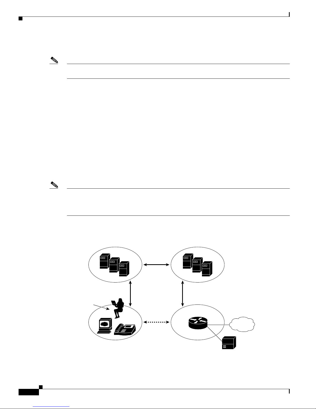
From an architecture standpoint, the physical components of a SIP network can also be grouped into two
categories: clie nts an d ser vers. Figure 1-1 illustrates the architecture of a SIP network.
Note In addition, the SIP s ervers c a n inte rac t w ith oth er a ppli cat ion serv ice s, suc h as Li ght weght Direc tor y
Access Protocol (LDAP) servers, a da tabase app lica tion , or a n eX ten sible M arkup Lan gua ge ( XML )
application. These application services provide back-end services such as directory, authentication, and
billing services.
Figure 1-1 SIP Architecture
SIP Proxy and
Redirect Servers
SIP
SIP SIP
SIP User
Agents (UA)
SIP Gateway
Cisco SIP IP Ph one Administrator Guide
1-2
IP
RTP
PSTN
Legacy PBX
42870
Page 19

Chapter 1 Product Overview
SIP Client s
SIP Server s
What Is the Cisco SIP IP Phone?
SIP clients include:
• Phones—Can ac t a s e ither a UAS or UAC. Softphones (PCs that have phone c apa bil ities i nsta lled)
and Cisco SIP IP phones can initiate SIP requests and respond to requests.
• Gateways—Provide call control. Gateways provide many services, the most common being a
translation function betwe en SI P conf e renc ing end point s and othe r term i nal t ypes. Thi s func ti on
includes translation between transmission formats and between communications procedures. In
addition, the gat eway also tra nsla tes bet wee n aud io a nd vid eo code cs a nd perf orm s c all setu p and
clearing on both the LA N si de and the switc hed-c irc uit n etwor k sid e.
SIP servers includ e:
• Proxy server—The pr oxy server is a n in term ed iate device tha t r ece ives SIP reques ts f rom a c li ent
and then forwards the re quests on the clie nt’s behalf. Basically , proxy servers receive SIP messages
and forward them to the next SIP server in the network. Proxy servers can provide functi o ns such as
authentication, authorization, network access control, routing, reliable request retransmission, and
security.
• Redirect server—Receives SIP requests, strips out the address in the request, checks its address
tables for any other addresses tha t may be mapp ed to the one in the reque st, and th en retur ns the
results of the address mapping to the client. Basically, redirect servers provide the client with
information about t he next hop or hops that a message should take an d then the client cont acts th e
next hop server or UAS directl y.
• Registra r se rv er —Processes requests from UACs for registration of their current location. Registrar
servers are often co-located with a redirect or proxy server.
What Is the Cisco SIP IP Phone?
Cisco SIP IP phones are full-featured telephones that can be plugged directly into an IP network and can
be used very much like a standard private branch exchange (PBX) telephone. The Cisco SIP IP phone is
an IP telephony inst ru ment t hat ca n b e use d in VoIP networks.
The Cisco SIP IP ph one mo del t erm i nals c an at tach t o t he exi sti ng data ne twork i nfras tr uct ure, via
10BASE-T/100BASE-T interfaces on a n E the rnet s witc h. Wh en use d with a voice- capa ble E the rnet
switch (one that understands type of service [ToS] bits and can prioritize VoIP traffic), the phones
eliminate the need for a traditional proprietary telephone set and key system and PBX.
The Cisco SIP IP phone complies with RFC 3261, as listed in Appendix A, “SIP Compliance with RFC
3261 Information”.
Figure 1-2 illustrates physical features of the Cisco SIP IP phone.
Cisco SIP IP Phone Administrator Guide
1-3
Page 20

What Is the Cisco SIP IP Phone?
Figure 1-2 Cisco SIP IP Phone Physical Features
Chapter 1 Product Overview
LCD
Handset
•
LCD screen—Desktop, which di sp lays inf orm ation a bout yo ur Ci sco SIP IP phone , suc h as the
Dialing
pad
Scroll
Line or speed dial
key
buttons
Function
toggles
Footstand
adjustment
Soft keys
i button
On-screen
mode buttons
Volume
buttons
38007
time, date, yo ur pho ne nu mb er, caller ID, li ne and ca ll sta tus a nd the soft key ta bs.
• Line or speed-dial buttons—Opens a new line or speed dials the number on the L CD screen .
• Footstand adjustment—Adjusts the angl e of t he p hon e base.
• Soft keys—Activate the feature described by the text message directly above on the LCD screen.
• Information (i) button—Provides online he lp for selec ted keys or features and ne twork statisti cs
about the active call. Displays a descriptor of the key directly after pressing the i button. For
example, pressing t he i button, then up or d own displa ys a scr een inst ru cting yo u h ow to scrol l u p
and down on the LCD.
• On-screen mode buttons—Retrieves information about current settings, recent calls, available
services, and voice-mail messages.
• Volume buttons—Adjust the volume of the handset, headset, speaker, and ringer and adjust the
brightness contrast settings on the LCD screen.
• Function toggles—In cl u des t he se op tio n s:
–
Headset and speaker—Toggles these functions ena bli ng yo u to answ er the pho ne u sing a
headset or speakerphone.
–
Mute—Stops or resumes voice transmission.
• Scroll key—Enables you to move among different soft key options displayed on LCD screen .
• Dialing pad—Press the dial-pad buttons to dial a phone number. Dial-pad buttons work exactly like
those on your existi ng t elepho ne .
• Handset—Lift the handset and press the dial-pad numbers to place a call, review voice-mail
messages, and answer a call.
Cisco SIP IP Ph one Administrator Guide
1-4
Page 21

Chapter 1 Product Overview
BTXML Support
Basic Telephony eXtensible Markup Language (BTXML) is supported on t he Cisco SIP IP phon e.
BTXML defines XML elements for controlling the user interface of an IP telephone. BTXML describes
what information i s d ispl ayed on the s cree n and h ow the use r provid es inpu t usi ng soft keys and ha rd
keys. User interface control is internal to the phone and there is no external BTXML user interface
control.
Cisco CallManager XML Support
The Cisco SIP IP phon e su p por ts cus to mer-written Cisco CallManager XML cards that ca n be acc es s ed
using buttons or softkeys on the phone. These cards can provid e data such as st ock quotes , calenda rs,
and directory lookups. The XML ca rds can be ac cessed by the fol lowing methods:
• From the Services soft key, configured using the services_url parameter.
• By pressing the i button.
• By pressing the dire ctory button and s electing External Direct ory , configur ed using the director y_url
parameter.
What Is the Cisco SIP IP Phone?
• By specifying a bitmap to be used as the phone's lo go (brandi ng), configured using th e logo_ur l
parameter.
See Chapter 3, “Managi ng Ci sco SI P IP Pho nes ” for information ab out configurin g these p aramete rs.
The Cisco SIP IP phone supports Cisco CallManger XML up to version 3.0. It does not support the XML
objects added in Cisc o Ca llMa nage r XM L version 3. 1:
• CiscoIPPhoneIconMenu
• CiscoIPPhoneExecute
• CiscoIPPhoneError
• CiscoIPPhoneResponse
• SoftKeyItem
The following exceptions apply to the Cisco SIP IP phone:
• External directories cannot be appended to the main list of directories under the directory button. If
external directori es are provisi on ed fo r the Ci sco SIP I P p hone , t he n th ey can be ac cesse d by
pressing the direct ory button and select ing the Ext ernal Di rector y option .
• The Cisco SI P IP ph one rem oves w hi te sp ac e whe n th e Ci sc o C all M an ag er XM L card s ar e
displayed. Multiple spaces are consolidated to a single space.
• Setting x and y coor dina tes fo r th e Cisco IPPho neIm age obje ct is not sup port ed. T he i m age always
appears at location 0,0 . Center ing of the image is not supp orted if x and y are set to -1.
• The Cisco SIP IP phone displays a ny v a lid titl e it re cei v es. Th is dif fe rs from the Cisco CallMan ager
phones in that the CiscoIPPhoneGraphicMenu object does not display a title even if it receives one
and the CiscoIPPhoneImag e objec t displays the pr evious menu item or “Services” rather than
received titles.
• Cisco CallManager phones allow embedded carriage returns and line feeds in menu items. In the
Cisco SIP IP phone, car riage re tur ns and li ne f eeds ar e discar de d.
• The Cisco SIP IP phone always displays the full set of di rectory sof tkeys. For Cisco CallManage r
phones, the softkeys can change depending on what type of object it receives. This is due to support
for Cisco CallManager 3.0 software.
Cisco SIP IP Phone Administrator Guide
1-5
Page 22

What Is the Cisco SIP IP Phone?
• A parameter is sent along with the initial request for a Services or Directory URL which
differentiates the Cisco SIP IP phone from othe r types of pho nes.
For more information a bout usin g XM L on your Ci sco SI P IP ph one, see t he fo llowing li nk s o r
documents:
• Cisco IP Phone Se rv ice fo rum at th e fo llowing U RL:
http://www.hotdispatch.com/cisco-ip-telephony
• Cisco CallManager Services Developer Kit at the following URL:
http://www.cisco.com/warp/public/570/avvid/voice_ip/cm_xml/cm_xmldown.shtml
• Developing Cisco IP Phone Services by Darrick Deel, Mark Nelson, and Anne Smith, ISBN
1-58705-060-9
Supported Features
In addition to the features illustrated in Figure 1-2 on page 1-4, the Cisco SIP IP phone also provides the
following features.
Chapter 1 Product Overview
Physical Features
Network Features
• Adjustable ring tone
• Hearing-aid compatible handset
• Headset compatibility
• Integrated two-port Ethernet switch that allows the telephone and a computer to share a single
Ethernet jack
• Direct connection to a 10BASE-T or 100 BASE-T Ethernet (RJ- 45) networ k (half- or full-du plex
connections are supp orte d)
• Large (4.25 x 3 in. or 10.79 cm. x 7.62 cm .) display w ith adjusta ble contra st
• IP address assignment—Dyna mic Host Configurati on Protoco l (DHCP) client or ma nuall y
configured via a loca l se tup menu .
• Network startup using D HCP a nd Trivial File Transfer Protocol (TFTP).
• Te lnet support—Allows the user to use Te lnet to connect directly to the Cisco SIP IP phone to debug
and troubleshoot the phone. See the “Managing C i s co S I P IP P ho n e s ” section on page 3-1 for more
information on configura tion p aram eters.
• Ping support—Allows the user to use ping to see if a Cisco SIP IP phone is operational and ho w long
the response time is from the phone.
• Traceroute support—Allows the user t o use trac erou te to se e the p ath tha t a C isco SIP IP phon e
traverses in the route to its desired destination.
Cisco SIP IP Ph one Administrator Guide
1-6
Page 23

Chapter 1 Product Overview
Configuration Features
The Cisco SIP IP phone provides the ability to:
• Configure Ethernet port mode and spe ed
• Register with or unregister from a proxy server
• Specify a TFTP bo ot d ire ctor y
• Configure a label for phone ide nti fication displ ay p urp oses
• Configure a name for caller identification purposes for each active line on a phone
• Configure a 12- or 2 4-hour use r i nte rface ti me d ispl ay
Codec and Protocol Support
• G.711 (u-law and a-law) and G.729a audio c ompre ssion.
• In-band dual tone mult ifrequency (D TMF) sup port for touc h-to ne dialin g.
• Out-of-band DT MF si gnal ing for cod ec s th at do not tr anspor t the DT MF sign ali ng corr ec tly ( fo r
example, G.729 or G .729 a) .
What Is the Cisco SIP IP Phone?
• Local (180 Ringi ng) o r r emot e (1 83 Sessio n Prog re ss) call progr es s ton e.
• Audio/Video Transport (AVT) payload type negotiation.
• Current date and time support via Simple Network Time Protocol (SNTP) and time zone and
Daylight Saving Time support.
• Call redirection infor mation supp ort via t he Diversion header.
• Third-party ca ll c ontr ol via d elaye d medi a negotia tio n. A de la yed m edi a negoti ation i s o ne w he re
the Session Description Protocol (SDP) information is not completely advertised in the initial call
setup.
• Support for endpoints specified as fully qual ified domain names (FQ DNs) in the SDP.
• Remote reset and d ial p lan up date suppo rt ( via the Event h eade r in N OTIFY messages).
Note See the “Supported Protocols” section on page 1-11 for additional supported protocols.
Dialing and Messaging Features
• Dial plan suppor t t hat ena bles a utom ati c di al ing and aut om atic g ener ati on of a sec ond ary d i al tone
• Local directory configuration (save and recall) and automatic dial completion—Each time a call is
successfully made or received, the number is stored in a local directory that is maintained on the
phone. The maximum num ber of en tries is 32. Entri es are aged- out bas ed on thei r usage and ag e.
The oldest entry called the least number of times is overwritten first. This feature cannot be
programmed by the user, however, up to 20 entries can be “locked” (via the Locked soft key) so that
they will never be deleted.
• Message W aiting Indication (via u nsolicited NOT IFY)—Lights to indicate that a new v oice message
is in a subscriber’s mailbox. If the subscriber listens to the message but does not save or delete the
message, the light remains on. If a subscriber listens to the new message or messages, and saves or
deletes them, the light goes of f. The message w aiting indi cator is contr olled b y the v oicemai l server.
The indication will be saved over a phone upgrade or reboot.
Cisco SIP IP Phone Administrator Guide
1-7
Page 24

What Is the Cisco SIP IP Phone?
• Speed dial to voice-mail via the messages button
• Do not disturb—Allows the user to instruct the system to intercept incoming calls during specified
periods of time when t he u ser d oe s no t want to be di sturbe d.
• Multiple directory numbers —Allows the Cisco SIP IP phone to have up to six directory numbers or
lines.
• Call waiting (enabled)—Plays an audible tone to indica te that an incoming call is waiting . Th e us er
can then put the existing call on hold and accept the other call. The user can alternate between the
two calls.
• Call waiting (disabled)—Allows the user to instruct the system to block call waiting calls during a
specified period of time.
• Direct number dialing—Allows users to initiate or receive a call using a standard E.164 number
format in a local, national, or international format.
• Direct URL dialing—Provides the ability to place a call using an e-mail address instead of a phone
number.
• Caller ID blocking—Allows the user to instruct the system to block phone number or e-mail address
from phones that have caller identification capabilities.
Chapter 1 Product Overview
Call Options
• Anonymous call blocking —Allows the user to instruct the system to block any calls for which the
identification is blocked.
• Three-way conferencing—Supports one phone conf eren ci ng w it h two oth er phone s by provid ing
mixing on the initiating phone. To set up a three-way conference call, see the “Making Conference
Calls” section in Chap ter 3 of the C isco IP Pho ne Models 7960 and 794 0 User Guide.
• Call forwa rd (netwo rk)—Allows the Cisco SIP IP phone user to request forwarding service from the
network (via a third-part y tool that enab les this fea ture to be configured) . When a call is pl aced to
the user’s phone, it is redirected to the appropriate forward destina tion by the SIP proxy se rver.
• Call hold—Allows the Cisco SIP IP phone user (user A) to place a call (from user B) on hold. When
user A places user B on hold, the two-way RTP voice path between user A and user B is temporarily
disconnected, but t he call session i s stil l connec ted. When user A tak es user B o ff hold, the two -way
RTP voice path is reestablished.
• Call transfer—Allows the Cisco SIP IP phone user (user A) to transfer a call from one user (user B)
to another user (u ser C). User A pla ces user B on hol d and calls user C. If user C accepts the tran sfer ,
a session is estab lish ed bet wee n user B and use r C an d t he ses s ion betw een u ser A a nd us er B is
terminated.
• Three-way calling—Allows a “bridged” three-way call. When a three-way call is established, the
Cisco SIP IP phone th rou gh whi ch t he c all i s es tablis hed a cts as a br idge , mi xin g th e au dio me dia
for the other parties.
Routing and Proxy Features
• User-defined proxy routing
The Route attribute of the template tag in the dial-plan template file can be used to indicate which
proxy (default, emergency, FQDN) that the call should be init ially route d to. For example, to
configure an emergency proxy, specify value of the Route attribute as “emergency.”
• Backup SIP proxy
Cisco SIP IP Ph one Administrator Guide
1-8
Page 25

Chapter 1 Product Overview
• Emergency SIP proxy
What Is the Cisco SIP IP Phone?
When the primary proxy does not respo nd to the INV ITE message se nt by the Cisco SIP IP Phone
after the configured number of retries, the Cisco SIP IP Phone sends the INVITE to the backup
proxy. This is independent from the pr oxy defined i n t he Ro ut e a ttri bute in t he d ial -pla n t empl ate
used.
The Cisco SIP IP phone does not have to register with the backup proxy. All interactions with the
backup proxy, such as authentication challenges, are treated the same as the interactions with the
primary proxy.
The backup proxy is used only wit h new INVITE messa ges. Once the back up proxy is used, i t is
active for the duration of the call.
The location of the bac kup SIP p rox y ca n be de fined a s an IP ad dress in the de fault c on figuration
file. See the proxy_backup an d proxy_ backu p_port pa rameter s in the “Modifying the Default SIP
Configuration File” section on page 3-8 .
An optional emergency SIP proxy can be configured with the Route attribute of the template tag in
the dial-plan template file. See “Support of user-defined proxy routi ng.”
When an emergency SIP pro xy is configured and a call is initiated, the p hone gen erates an IN VITE
message to the addre ss spec ified in t he pr ox y_eme rgency para met er. The emergency proxy is used
for the call duration.
The location of the emergency pro xy can be defined as an IP address i n the default configurati on
file. See the proxy_emergency and proxy_ emergen cy_port para meters in “Modifyin g th e D efau lt
SIP Configuration File” section on page 3 -8.
• Support of DNS SRV
The Domain Name Server RR (DNS SRV) is used to locate servers for a given service.
SIP on Cisco’s SIP IP phones uses a DNS SRV query to determine the IP address of th e SI P proxy
or redirect server. The query str ing gen er ate d i s in co mpl ia nce w ith RFC 2782, a nd pr ep en ds th e
protocol label w ith a n und er score _, as in “_protocol._transp ort. ” The addition of the unde rscore
reduces the risk of the same name being used for unre lated pur poses.
In compliance with RFC 2782 and the draft-ietf-sip-srv-01 specification, the system can remember
multiple IP addresses and use them properly. In the draft-ietf-sip-srv-01 specification, it is assumed
that all proxies returned for the SRV record are equivalent such that the p h one can register with any
of the proxies an d i niti ate a ca ll us ing a ny othe r pr oxy.
• Configurable Voice Activity Detection
Voice Activity Detection (VAD) can be enabled or disabled with enable _v ad par ameter. Use a v alue
of 0 to disable, and a value of 1 to enable. See enable_vad parameter in “Modifying the Default SIP
Configuration File” section on page 3-8.
• Distinctive Alerting
If the INVITE message contains an Alert-Info header, distinctive ringing is invoked. The format of
the header is “Alert-inf o: x ”. Th e value of “x” can be any number. This header is only received by
the phone and is not generate d by the phone.
Distinctive ringing is supported when the phone is idle or during a call. In the idle mode, the phone
rings with a different cadence. The selec t ed ri ng in g t yp e p lay s twice with a short pause in betwe en .
In call-waiting mode, two short beeps are generated instead of one long beep.
• Network Address Translation (NAT) and Outbound Proxy
NAT can be enabled or dis abled with th e nat_e nable p aramete r . You can configur e the address o f the
NAT o r firewall server u sing t he na t_a ddr es s para m eter.
Cisco SIP IP Phone Administrator Guide
1-9
Page 26

What Is the Cisco SIP IP Phone?
You can configure the IP address and port numbe r of the out bound proxy se rver. When outbound
proxy is enabled, a ll SIP re quests a re sen t t o th e outb ound p roxy se r ver inste ad o f t he
proxyN_address. All respo nses continu e to follow the using the norm al Via processing rules. The
media stream is no t rout ed t hroug h the out boun d p rox y.
NAT and outbound pro xy modes can be indepe ndently en abled or disa bled. Th e received= tag is
added to the Via header of all re spon ses if there is n o received= ta g in the up permos t Via he ader an d
the source IP ad dress is di fferent f rom the IP add ress i n the uppe rm ost Via header. Responses are
sent back to the source under the following conditions:
Note For information on how to use the standard telephony features and URL dialing, refer to the documents
listed in the “Related Documentation” section on page -viii.
Chapter 1 Product Overview
–
If a received= tag is in t he up pe rmo st Via header, the re spon se i s sent back to t he IP a ddr ess
contained in the received= tag.
–
If there is no received= tag and the IP address in the uppermost Via header is different than the
source IP address, the response is sent back to the source IP. Otherwise the response is sent back
to the IP address in the uppermost Via header.
Character Support
Note The XML cards, info text, and menus are all in English. These items are built into the phone image and
The Cisco SIP IP ph one s uppo rts the ISO 8 859 -1 Lat in1 ch ara cters. T he fo l lowing la ngu ag es a re
supported:
French (fr), Spanish (es), Cata lan (ca), Basque (eu) , Portu guese (pt ), Italia n (it), Alba nian (sq) ,
Rhaeto-Romanic (rm), Dutch (nl) , German (de), Danish (da), Swedish (sv), Nor wegian (no), Finnish (f i),
Faroese (fo), Icelandic (is), Irish (ga), Scottish (gd), English (en), Afrikaans (af) and Swahili (sw).
The following languages ar e not supp orted:
Zulu (zu) and other Bantu languages usi ng Latin Ext ended -B letter s, Arabi c in North Afri ca, and
Guarani (gn) missing GEIUY with ~ tilde.
cannot be ch ange d.
ISO 8859-1 Latin1 char acters ca n be used in th e following areas:
• Caller ID information. When a SIP message is received with ISO 8859-1 Latin1 characters in the
caller ID strings, those caller ID strings are displayed on the Cisco SIP IP phone's LCD screen with
the correct ISO 8859-1 Latin1 characters.
• Services menu applications written in CMXML. The customer can develop language-specific
applications for a pa rticular region. F or e x am ple, an application that displayed the current wea th er
in Sweden using Swedish langu age ch aracte rs can be disp layed on the Cisco SIP IP phone. If th e
customer de velo ps the same applicati on for a Sp anish t ow n, they could tr anslat e the applica tion into
Spanish.
• Line key labels. The line keys can be configured to support the Latin1 character. The line key name
can be specified in the c onf ig f ile and it will be display ed corr ectly. The Latin1 characters cannot be
used in the lineX_name, but can be used in the lin eX_shor tname a nd lineX_d isplay name. If the
proxy supports L atin1 characters i n the To/From headers, then they can be used in the lineX_name
parameter as well.
Cisco SIP IP Ph one Administrator Guide
1-10
Page 27

Chapter 1 Product Overview
Supported Protocols
The Cisco SIP IP ph one s uppo rt s th e fo llowing sta nda rd pr otoc ols:
• Domain Name S yste m (DNS )—Used in the Internet for translating names of network nodes into
addresses. SIP uses D NS t o re solve th e host na mes o f endpoi n ts to IP a dd resses.
• Dynamic Host Control Pr otocol (D HCP)—Used to dynamically allocate and assign IP addresses.
DHCP allows you to move network devices from one subnet to another without admi nistrative
attention. If using DHCP, you can connect Cisco SIP IP phones to the network and become
operational withou t having to man ua lly a ssign an I P addr ess a nd ad di tiona l ne twor k par amet ers.
The Cisco SIP IP ph one com pli es w ith t he DHCP spe cifications do cu ment ed i n RFC 2131. By
default, Cisco SIP IP ph ones ar e DHC P-e nabled .
• Internet Control Message Protocol (ICMP)—A network layer Internet protocol that enables hosts to
send error or con trol mess age s to oth er ho sts. ICMP al so provid es othe r i nfo rmati on rel evant to IP
packet processing.
The Cisco SIP suppo rts I CMP as i t is doc umen t ed in RFC 792 .
• Internet Protocol (IP)—A network layer protocol that sends datagram packets between nodes on the
Internet. IP also provides features for addressing, type-of-service (T oS) specification, fragmentation
and reassembl y, and security.
What Is the Cisco SIP IP Phone?
The Cisco SIP IP ph one s uppo rts IP a s it i s defined i n RFC 79 1.
• Real-Time Transport Protocol (RTP)—Transports re al -ti me d ata ( suc h as voice da ta ) over da ta
networks. RTP also has the ability to obtain quality of service (QoS) information.
The Cisco SIP IP ph one s uppo rts RTP as a media cha nnel.
• Session Description Protocol (SDP)—An ASCII-based protocol that describes multimedia sessions
and their related sche duling info rmat ion.
The Cisco SIP IP ph one u ses SD P for sessi on descr iptio n.
• Simple Network Time Protocol (SNTP)—Sychronizes com pute r clocks on a n IP n etwor k. The
Cisco SIP IP phone s use SNTP for thei r date and tim e support.
• Transmission Control Protocol (TCP)—Provides a reliable byte-stream transfer service betwee n two
endpoints on an inter net . The Cisco SIP IP pho ne suppor ts TCP f or Telnet sessions only.
• Triv ial File Transfer Protocol (TFTP)—Allows f iles to be transferre d from one com puter to an other
over a network. The Cisco SIP IP phone uses TFTP to download configuration files and software
updates.
• User Datagram Pr ot ocol (U DP )—A simple protocol that exchanges data packets without
acknowledgments or guara nteed delivery. SIP can use UD P as the underlying transport protocol. If
UDP is used, retransmissions are used to ensure reliability.
The Cisco SIP IP ph one s uppo rts UDP as it i s defined in RFC 76 8 for SI P signa ling .
• Hypertext Transfer Protocol (HT TP) —The phone contains limi ted suppor t for HTTP 1.1. The
phone uses HTTP to retrieve Cisco CallManager XML files.
Cisco SIP IP Phone Administrator Guide
1-11
Page 28

Prerequisites
Prerequisites
For the Cisco SIP IP phone to successfully operate as a SIP endpoint in your network, your network must
meet the following requirements:
• A working IP network is established.
• VoIP is configured on your Cisco routers.
• VoIP gateways are configured for SIP.
• A TFTP server is active and contains the latest Cisco SIP IP phone firmware image in its root
• A proxy server is active and configured to receive and forward SIP messages.
Chapter 1 Product Overview
For more information abou t configuring IP, refer to Cisco IOS IP Configuration Guide,
Release 12.2.
For more information about configuring VoIP, refer to the Cisco IOS Voice, Video, and Fax
Configuration Guide, Release 12.2, for the appropriate access platform. F or more info rmation about
configuring SIP VoIP, refer to the “Configuring SIP for VoIP” chapter.
directory.
Cisco SIP IP Phone Connections
The Cisco SIP IP phone has connections for connect i ng to the data network, for providing power to the
phone, and for connecting a headset to the phone. Figure 1-3 illustrates the connections on the Cisco SIP
IP phone.
Figure 1-3 Cisco SIP IP Phone Cable Connections
Cisco IP Phone (rear view)
Power
outlet
AC adapter
port
(DC48V)
(optional power
cable)
RS-232 port
Headset
port
Handset
port
Cisco SIP IP Ph one Administrator Guide
1-12
Network port
(10/100 SW)
Access port
(10/100 PC)
62472
Page 29

Chapter 1 Product Overview
Connecting to the Network
The Cisco SIP IP phone has two RJ-45 ports that each support 10/100 Mbps half- or full-duplex Ethernet
connections to ext erna l devices —network port (labeled 10 /100 SW) and acc ess port (labe led
10/100 PC). You can use either Category 3 or 5 cabling for 10 Mpbs connections, but use Category 5 for
100 Mbps connect ions. On bo th t he n etwor k port and acc ess port , use f ull -dupl ex mode to avoid
collisions.
Network Port (10/100 SW)
Use the network port to connect the phone to the network. You must use a straight-through cable on this
port. The phone can also obtain inline power from the Catalyst switch over this connection. See the
“Connecti ng to Power” section on pa ge 1- 13 for details.
Access Port (10/100 PC)
Use the access port to connect a network device, such as a computer, to the phone. You must use a
straight-through cable o n thi s port .
Cisco SIP IP Phone Connections
Connecting to Power
The Cisco SIP IP phone can be powered by the following sources:
• External power source—Optional Cisco AC adapter and power cord for connecting to a standard
wall receptacle.
• WS-X6348-RJ45V 10/100 sw itchin g m odu le—Provides inline power to the C isco SIP IP phon e
when connected to a Ca ta lyst 3500, 4 000 , or 600 0 fa mily 10/10 0BASE-TX sw itchi ng modu le.
This module send s power on pin s 1 and 2, and 3 an d 6 .
• WS-PWR-PANEL—Power patch panel provides power to the Cisco SIP IP phone, which allows the
Cisco SIP IP phone to be con ne cted to existi ng Catal yst 4 000 , 5000, a nd 6000 fa mil y
10/100BASE-TX switching modules.
This module sends p ower on p in s 4 , 5, 7, and 8.
• WS-X4148-RJ45V—48-port 10/100 Eth erne t w ith i nline p ower modu le for t he C ata lyst 4006.
• WS-X4095-PEM—VoIP DC Power Entry module for the Catalyst 4006.
• WS-X4608-2PSU and W S-X 460 8—External -48V DC power shelf common equipment for the
Catalyst 4006 with two AC-to-DC power suppl y units (PSU s) an d one emp ty b ay f or redun da nt
option, and the 110V 15A AC-to-48V DC PSU redu ndant opti on for the power shel f.
• WS-C3524-PWR-XL-EN—Catalyst 3524-PWR XL switch.
Note Only the network port (labeled 10/100 SW) supports inline power from the Catalyst switches.
For redundancy, you can use the Cisco AC adapter even if you are using i n line power from the Catalyst
switches. The Cisco SIP IP phone can share the power load being used from the inline power and external
power source. If either the inline power or the external power goes down, the phone can switch entirely
to the other power source.
Cisco SIP IP Phone Administrator Guide
1-13
Page 30

The Cisco SIP IP Phone with a Catalyst Switch
T o use this redundancy feature you must set the inline power mode to auto on the Cisco Ca taly st switch .
Next, connect the unpowered Cisco SIP IP phone to the network. After the phone powers up, connect the
external power supply to the phone.
Using a Headset
The Cisco SIP IP ph one su ppo rts a fou r- or six -wire hea dset jack. Spec ifically, the Cisco SIP IP pho ne
supports the following Plantronics headset models:
• Tristar Monaural
• Encore Monaur al H91
• Encore Binaura l H 101
The volume and mute controls also adjust volume to the earpiece and mute the speech path of the
headset. The headset activation key is located on the front of the Cisco SIP IP phone.
Note When using a headset, an amplifier is not required. However, a coil cord is required to connect the
headset to the headset port on the back of your Cisco IP Pho ne 7960/7940. For information on ordering
compatible headset s and coil cord s for the Cisco IP Phone 7960/7460 , go to the fol lowing URL:
Chapter 1 Product Overview
http://cisco.getheadsets.com or http://vxicorp.com/cisco
The Cisco SIP IP Phone with a Ca talyst Switch
To function in the IP telephony network, the Cisco SIP IP phone must be connec ted to a networking
device, such as a Catalyst switch, to obtain network connectivity.
The Cisco SIP IP phone has an internal Ethernet switch, which enables it to switch traffic coming from
the phone, access port, and t he network port .
If a computer is connected to the access port, packets traveling to and from the computer and to and from
the phone share t he sa me physi cal lin k to the swi tch and the same port on t he sw itch .
This configuration has these implications for the VLAN configuration on the network:
• The current VLANs might be configure d on an IP subnet ba sis, and add itional IP add resse s might
not be available to assign the pho ne t o a por t so tha t i t be long s to the same su bnet as o ther devices
(PC) connected to the same port.
• Data traffic present on t he V LAN supp ort ing ph ones mi ght reduc e t he q ua lity of VoIP traffic.
You can resolve these issues by isolating the voice traffic onto a separate VLAN on each of the ports
connected to a p hon e. T he swi tch port configure d f or conne c ting a p hone would have separa te VL ANs
configured for ca rr ying :
• Voice traffic to and from the Cisco SIP IP pho ne (a ux ilia ry VLAN )
• Data traffic to and from the PC connected to the switch through the access port of the Cisco SIP IP
phone (native VLAN)
Isolating the phones on a separate, auxiliary VLAN increases the quality of the voice traffic and allows
a large number of phones to be added to an existing net work whe re there are not enough IP address es.
For more information, refer to the documentation included with the Catalyst switch or available online
at the following URL:
Cisco SIP IP Ph one Administrator Guide
1-14
Page 31

Chapter 1 Product Overview
http://www.cisco.com/univercd/home/home.htm
The Cisco SIP IP Phone with a Catalyst Switch
Cisco SIP IP Phone Administrator Guide
1-15
Page 32

The Cisco SIP IP Phone with a Catalyst Switch
Chapter 1 Product Overview
Cisco SIP IP Ph one Administrator Guide
1-16
Page 33

CHAPTER
2
Getting Started with Your Cisco SIP IP Phone
This chapter explains the Cisco SIP IP phone initialization and the process that you should follow to
install and conne ct the Cisco SI P I P ph one.
This chapter provides the following major sections:
• Initialization Process Overvi ew, page 2-1
• Installing the Cisco SI P I P Pho ne, page 2-2
• Verifying Startup, page 2-14
• Using the Cisco SIP IP Phone Menu Interface , page 2-15
• Reading the Cisco SI P IP Phone Icons, page 2-15
• Customizing the Cisco SIP IP Phone Ring Types, page 2-17
• Creating Dial Plan s, page 2 -17
Initialization Process Overview
The initialization process of the Cisco SIP IP phone is responsib le for establishing netw ork connect i vity
and for makin g the pho ne op er at ion al i n y our I P ne t work.
Once you connec t y our ph one to t he n et work an d to an el ectri ca l sup pl y, the phone begins i ts
initialization process.
During the initialization process, the following events take place:
1. The stored image is loaded.
The Cisco SIP IP phone has nonvolatile Flash memory in which it stores the firmware images,
user-defined preferences, and permanent factory information about the phone.
During initialization, the phone runs a bootstrap loader that loads and executes the phone image
stored in Flash memory.
2. The VLAN is configured.
If the Cisco SIP IP phone is connected to a Catalyst switch, the switch notifies the phone of the voice
VLAN defined on the switch. The phone needs to know its VLAN membership before it can proceed
with the Dynamic Host Configuration Protocol (DHCP) request for its IP settings (if using DHCP).
3. An IP a dd re s s is acquired.
Cisco SIP IP Phone Administrator Guide
2-1
Page 34

Installing the Cisco SIP IP Phon e
If the Cisco SIP IP phone is using DHCP to obta in the IP settings, the phone qu eries the D HCP
server. If the phone is not using DHCP, then the phone uses IP settings that ar e stored i n Flash
memory.
4. The TFT P s erver i s c on t act ed .
The TFTP server c onta ins t he l atest Cisc o SIP IP p hone firmware im ag e and t h e dual boot file
(OS79XX.TXT) that enables the phone to automatically determine and initialize for the VoIP
environment in which it is being installed.
If the phone is using the TFTP server to obtain its SIP parameters, there should also be a
configuration file or files o n t he TFT P se rver t ha t the p hon e will r e quest and downlo ad. In th e
configuration file or files, SIP parameters that are require d by the phone to oper ate in a SIP VoIP
environment are defined. If the phone is not obta ining its SIP para meters via the TFTP server, the
phone uses SIP sett ings tha t are stor ed in Flash m emory.
5. The firmware vers io n is veri fied.
If the phone is obtaining its SIP parameters via a TFTP serv er, the config uratio n fil es are req uested.
If the phone determines that the image defined in a configuration file differs from the image it has
stored in Flash memory, it performs a firmware upgrade.
When performing a firmware upgr ade, the phone downloads the firmware ima ge from th e TFTP
server, programs the image into Flash memo ry, and reboots.
Chapter 2 Getting Started with Your Cisco SIP IP Phone
Installing the Cisco SIP IP Phone
This section conta ins infor mat ion on how to insta ll Ci sco SIP I P p hon es i n y our I P ne twork. Be fore
getting started, read over the information in this section carefully.
Installation Task Summary
To successfully install the Cisco SIP IP phone, complete the following steps:
Step 1 Download the required file s from Cisco.com to th e TFTP serv er as describ ed in the “Downloadi ng Files
to Your TFTP Server” section on page 2- 3.
Step 2 If you are configuring SIP paramet ers via a TFTP se rver, create and store the co nfiguration files as
described in the “Configuring SIP Parameter s via a TFTP Server” section on page 2-4.
Step 3 If you are using DCHP to configur e the phone s’ network settings, configure the required network
parameters on your DHCP server as described in the “Configuring Network Parameters via a DHCP
Server” section on page 2-10.
Step 4 Connect the phone to the net work and to a power supply as de scribed in the “Connecting the Phone”
section on page 2-11.
Step 5 If you are not using DHCP to configur e network para meters, manua lly configure the required network
parameters as described in the “Manually Configuring the Network Parameters” section on page 2-10.
Step 6 If you are not configuring th e SIP parame ters via a TFTP server, manually configur e the requ ired
parameters as described in the “Manually Configuring the SIP Parameters” section on page 2-7 .
Cisco SIP IP Ph one Administrator Guide
2-2
Page 35

Chapter 2 Getting Started with Y our Cisco SIP IP Phone
Installing the Cisco SIP IP Phone
Downloading Files to Your TFTP Server
Before installing the Cisco SIP IP phones, copy the following files from Cisco.com to the root directory
of your TFTP server.
File Required or Optional Description
OS79XX.TXT Required Enables the phone to automatically determine and initialize for
the VoIP environment in which it is being installed.
After downloadin g this file , you must use an ASCII edi tor to open
it and specify the file name (without the file extension) of the
image version that yo u plan to run o n y our ph one s.
SIPDefaultGeneric.cnf Optional File in which to configure SIP parameters intended for all phones.
For more information on using the SIPDefault.cnf file, see the
“Creating the De fault SI P Configurati on Fi le” section on
page 2-5.
SIPConfigGeneric.cnf Required File that can be used as a template to configure SIP parameters
specific to a phone. When customized for a phone, this file must
be renamed to the MAC address of the phone.
RINGLIST.DAT Optional Lists audio files that are the custom ring type options for the
phones. The audio files listed in the RINGL IST.DAT file must
also be in the root directory of t he TFTP server.
For more information on custom ring types, see the “Customizing
the Cisco SIP IP Phone Ring Types” section on page 2-17.
P0S3xxyy.bin Required The Cisco SIP IP phone firmware image. The xx variable
represents the version numbe r, and yy is the sub-version number.
Note Applies to Cisco SIP IP Phone Release 2.3 and earlier.
P0S3-xx-y-zz.bin Required The Cisco SIP IP phone firmware image. The xx variable
represents the major version num ber, y is the minor version
number, and zz is the sub-version numbe r.
Note Applies to Cisco SIP IP Phone Release 3.0 and later.
dialplan.xml Optional North American sample dial plan. The dialplan.xml file can be
pushed down to the phones using a NOTIFY with a check-sync
Event header.
syncinfo.xml Optional Controls th e imag e version and associated syn ch ron i za tio n value
to be used for re mot e re boo ts.
Configuring SIP Parameters
Note This section desc ribe s how to configure the b asic SI P pa ram ete rs th at ar e re qu ired f or t he ph one to
operate in a SIP V oIP en vironment. For a complete list of the SIP parameters that you can configure, see
the “Modifying the Phon e’s SIP Settings” section on page 3- 5.
Cisco SIP IP Phone Administrator Guide
2-3
Page 36

Installing the Cisco SIP IP Phon e
The SIP parameters are those para meters th at a Cisco SIP IP phone needs to operat e in a SIP VoIP
environment. You can configure SIP p ar ame ters via a TF TP server, or you c an ma nual ly c on figure th e
parameters on a pho ne-by-pho ne basi s aft er co nnec tin g th e phone s.
When the phone initializes, it loads the parameters stored in Flash memory . After load ing the parameters
stored in Flash me mory, the phone re quest s the de fault c onfigura tion file from th e T FTP server. If the
default configuration file has been c onfigure d a nd st or ed in the ro ot d ire ctor y of the T FTP server, the
phone reads the parameters defined in the file, a n d stores those parameters that differ in Flas h memory.
The phone then requests its phone-specific configuration file. If the phone-specific configuration file has
been configured and placed on the TFTP server (in the root directory or a subdirectory), the phone reads
the parameters de fined in t he file and st ores those p aram eters t hat differ in Fla sh m emor y.
Therefore, whe n configur ing SI P p aram ete rs, r em embe r t he fo l lowing:
• Parameters defined in the default configuration file override the values stored in Flash memory.
• Parameters defined in the phone-specific configuration file override the values specified in the
default configuration file.
• Parameters entered locally are used by the phone until the next reboot (if a phone-specific
configuration file exists).
• If you choose n ot t o co nfigure the ph one v i a a TFT P s er ver, you must ma na ge t he pho ne loc ally.
Chapter 2 Getting Started with Your Cisco SIP IP Phone
Configuring SIP Parameters via a TFTP Server
If you are co nfiguring SI P p aram ete rs vi a a T FTP server, you must u se co nfigurat ion files.
There are two configuration files that you can use to define the SIP parameters; the default configuration
file (optional) and the phone-sp ecific configuration file (re quired). If you choose to use a default
configuration file, you m ust store the file in the root d ire ctor y of you r TFT P se rver. Phone-specific
configuration files can be stor ed in t he ro ot di rect or y or i n a subd irec to ry i n whi ch a ll ph one-s pec ific
configuration files ar e store d.
Except for par amete rs used to define t he l ine s and u ser s o n a phon e, al l ot her SI P para met ers ca n be
defined in either the default co nfiguration file or th e phone-sp ecific configura tion file. However, for
network control and maintenance purposes, we recommend that you define the parameters that you want
to apply to all phones in the default configuration file (SIPDefault.cnf). Phone-specific parameters
should only be defined via a phone-specific configuration file or be manually configured. Phone-specific
parameters should not be d efined in t he d efaul t configu ratio n file.
Configuration File Guidelines
When modifying the defaul t configurat ion file and creat ing the ph one-spec ific configurat ion files,
adhere to the f ol lowing gu ide lin es and re quir emen ts:
• SIP parameters specifie d in the default conf iguration fil e (SIPDefault.cnf) o verride those p arameters
stored in Flash memory. Parameters specified in a phone-speci fic configuration file override tho se
stored in Flash memory and parameters specified in the default configuration file.
• The name of each phon e’s phone-specific c onfiguratio n file i s u nique and is bas ed on the MAC
address of the phone.
The format of the file name must be SIPXXXXYYYYZZZZ.cnf, where XXXXYYYYZZZZ is the MAC
address of the p hone. The M AC address mu st be in uppe rcase , and the cnf extens ion m ust be in
lowercase (for example, SIP00503 EFFD84 2.c nf).
Cisco SIP IP Ph one Administrator Guide
2-4
Page 37

Chapter 2 Getting Started with Y our Cisco SIP IP Phone
Note The MAC address of a phone is identified on the middle sticker adhered to the base of the phone
and can also be v iewed o n th e Net work Configura tio n m enu .
• The default configurat ion fil e mu st be s to red i n t he r oot di rec tory of the TF TP server. The
phone-specific configuration file can be stored in the root directory or in a subdirectory in which all
phone-specific configuration files are located.
• Each line in the configuration files must use the following format:
variable-name : value ; optional comments
• Use colons to se para te variabl e na mes an d values.
• Only one value can be associated with a variable.
• The variable and value can contain white space before or after them and can contain any characters.
Howe ver , if white spaces ar e need ed within the v alue, the v alue must be enclosed in sing le or do uble
quotes. If the value is enclosed in quote s, the end quo te must be the sam e as the start quot e.
• After the valu e, you can incl ude optio nal com ments. Use the sem icolon (; ) and p ound (#) delimiter s
to distinguish the comments.
Installing the Cisco SIP IP Phone
• Blank lines ar e allowed.
• Comment lines are a llowed.
• Variable names are not case sensitive.
• Only one variable can be set per line.
• Distinguish the end of a line using <lf> or <cr>< lf>.
• The variable and value must be on the same line and cannot break the line.
• Except for parameters use d to defined the lines and use rs on a phone , all other SIP par ameters ca n
be defined in either the default configuration file or the phone-specific configuration file. However,
for network cont rol an d ma in ten ance p urp oses, Ci sco r ec om mends t hat yo u define th e para met ers
that you want to apply to all phones in the default configuration file (SIPDefault.cnf).
Creating the Default SIP Configurati on File
In the default configurat ion file ( SIPDefault .cnf), Cisco recommen ds that you defi ne the SIP parameters
that will be common to all of you r phones suc h as the image _versio n paramet er and call environment
parameters (for example, you will want to consider if the phones are required to register with a proxy
server, and which codec the phones will use when initiating a call).
By maintaining these parameters in the default configuration file, you can perform global changes, such
as upgrading the image version, without having to modify the phone-specific configuration file for each
phone.
Before You Begin
• Ensure that you have downloaded the SIPDefault.cnf file from Cisco.com to the root dire ctory of
your TFTP server.
• Review the guidelines and restrictions docum ent ed in the “Configuration File Guidelines” section
on page 2-4.
• For a complete list of the SIP parameters that you can configure, see the “Modify ing the Phon e’s
SIP Settings” section on page 3-5.
Cisco SIP IP Phone Administrator Guide
2-5
Page 38

Installing the Cisco SIP IP Phon e
Procedure
Step 1 Using an ASCII editor, open the SIPDefault.cnf file and define values for the following SIP global
parameters:
• image_version—(Required) Firmware version that th e Ci sco SI P I P ph one s houl d ru n.
Enter the name of the image version (as it is released by Cisco). Do not enter the extension. You
cannot change the image v ersion b y changing the fi le name, beca use the v ersion is also b uil t into the
file header. Trying to change the image version by changing the file name causes the firmware to fail
when it compares the version in the header against the file name.
• proxy1_address—( Required) IP address of the primary SIP proxy server that will be used by the
phones.
• tftp_cfg_dir—(Required if phone-specific configuration files are located in a subdirectory) Path to
the TFTP subdirectory in which phone-specific configuration files are stored.
Step 2 Save the file with the same file name, SIPDefault.cnf, to the root directory of your TFTP server.
The following is an exam ple of a SI P d efau lt co nfigur atio n file:
; sip default configuration file
Chapter 2 Getting Started with Your Cisco SIP IP Phone
#Image Version
image_version:P0S3-xx-y-zz ;
#Proxy server address
proxy1_address: 192.168.1.1 ;
#Subdirectory config file location
tftp_cfg_dir: /tftpboot/configs/sipphone
Creating the Phone-Specific SIP Confi gurat ion File
In the phone-specific SIP configurat ion file, define the param eters th at are spe cific to a phone such as
the lines configured on a pho ne and t he us er s define d for thos e lin es.
Before You Begin
• Review the guidelines and restrictions docum ent ed in the “Configuration File Guidelines” section
on page 2-4.
• Line parameters (those identified as linex) define a line on the phone. If you configure a line to use
an e-mail address, that line can only be called using an e-mail a d dress. Simi lar ly, if you configure a
line to use a nu mb er, that line ca n only be c a lled using t he nu mb er. Each line can have a di fferent
proxy configured.
• For a complete list of the SIP parameters that you can configure, see the “Modify ing the Phon e’s
SIP Settings” section on page 3-5.
Procedure
Step 1 Using an ASCII editor, create a phone-specific configuration file for each phone that you plan to install.
In the phone-specific configuration file, define values for the following SIP parameters (where x is a
number 1 through 6):
Cisco SIP IP Ph one Administrator Guide
2-6
Page 39

Chapter 2 Getting Started with Y our Cisco SIP IP Phone
• linex_name—(Required) Number or e-mail address used when registering. When entering a number,
enter the numb er wi thou t a ny das he s. For examp le, e nter 5 55-121 2 a s 555 121 2. When en ter in g an
e-mail address, ent er the e-m ail ID without the ho st na me.
• linex_authname—(Required when registration is enabled and the proxy server requires
authentication) Name used by the phone for authentication if a registration is challenged by the
proxy server during initializa tion. If a value is not configured for the linex_authname parameter
when registration is e nabl ed, the d efault name is use d. T he defau lt name is U NPROVISIONED.
• linex_password—(Required when registration is enabled and the proxy requires authentication)
Password used by the pho ne f or au then tic at ion if a r egistrati on is c hal len ged by the p rox y server
during initialization. If a v alue i s not con figu red for the linex_password parameter when registration
is enabled, the default logical passw ord is used. The default logica l password is UNPR O VISIONED.
Step 2 Save the file to your TFTP server (in the root directory or a subdirectory containing all the phone-specific
configuration f iles). Na me the f ile SIPXXXXYYYYZZZZ.cnf wher e XXXXYYYYZZZZ is the MAC address
of the phone. The MAC address must be i n up perc as e and t he extensi on , cnf, must be in l owercase (fo r
example, SIP00503EFFD842 .cnf) .
The following is an example of a configuration file:
; phone-specific configuration file sample
; Line 1 phone number
line1_name : 5551212
Installing the Cisco SIP IP Phone
; Line 1 name for authentication with proxy server
line1_authname : 5551212
; Line 1 authentication name password
line1_password : password
Manually Configuring the SIP Parameters
If you did not configure the SIP parameters via a TFTP se rver, you must manually configure them after
you have connected the phone as describe d in the “Connecting the Phone” section on page 2-11.
Before You Begin
• Connect your phone as descri bed in the “Connecting the Phon e” section on page 2-11.
• Unlock configuration mode a s describe d in the “Unlocking C onfigura tio n Mo de” section on
page 3-2. By default, the SIP parameters are locked to ensure that end user s cann ot modify settings
that might affect their call capabilities.
• Review the guidelines on using the Cisco SIP IP phone menus docume nted in the
“Using the Cisco SIP IP Phone Menu Interface” section on page 2-15.
• When configuring the Prefe rred Co dec a nd Out of Ba nd DT MF para met ers, p re ss the Change soft
key until the option you desire is displayed and then press the Save soft key.
• After making your changes, relock configuration mode as described i n t he “Locking Configuration
Mode” section on page 3-2.
• For a complete list of the SIP parameters that you can configure, see the “Modify ing the Phon e’s
SIP Settings” section on page 3-5.
Cisco SIP IP Phone Administrator Guide
2-7
Page 40

Installing the Cisco SIP IP Phon e
Procedure
Step 1 Press the settings key. The Settings menu is displayed.
Step 2 Highlight SIP Configuration. The SIP Configuration menu is displa yed.
Step 3 Highlight Line 1 Settings.
Step 4 Press the Select soft key. The Line 1 Configuration menu i s d ispl ayed.
Step 5 Highlight and pre ss the Select soft key to co nfigure the pa rame ter s sh own in Table 2-1:
Table 2-1 Manual SIP Configuration Parameters
Parameter Required or Optional Description
Name Required Number or e-mail address used when registering.
Shortname Optional Name or number associat ed with th e linex_name as
Authenti cation
Name
Authenti cation
Password
Display Name Optional Identification as it should appear for
Required when
registration is enabled
Required when
registration is enabled
Chapter 2 Getting Started with Your Cisco SIP IP Phone
When entering a number , enter the number without a ny
dashes. For example, ent er 5 55- 121 2 as 555 121 2.
When entering an e-mail address, enter the e-mail ID
without the host name.
you want it to display on the phone’s LCD if the
linex_name value exceeds the dis play ar ea. For
example, if the linex_name value is the phone number
111-222-333-4444, you can sp eci fy 34 444 fo r this
parameter to have 3444 display on the LCD instead.
Alternately, if the value for the linex_name parameter
is the email address “username@company.com,” you
can specify the “use rname” to have just the user name
appear on the LCD instead. This para meter is used f or
display purposes only. If a value is not specified for
this parameter, the value in the Name variable is
displayed.
Name used by the phone for auth entic ation if a
registration is challenged by the proxy server during
initialization. If a value is not configured for the
Authentication Name parameter when registration is
enabled, the default name is used. The defau lt name is
UNPROVISIONED.
Password used by the phone for authentication if a
registration is challenged by the proxy server during
initialization. If a value is not configured for the
Authentication Password param eter w he n registrat ion
is enabled, the default logical password is used. The
default password is UNPROVISIONED.
caller-id entif icati on pu rpos es. Fo r e xam ple, ins tead o f
jdoe@company.com displaying on phones that have
caller ID, you can specify John Doe in this parameter
to have John Doe display on t he ca lled pa rty end
instead. If a value is not specified for this parameter,
the Name value is used.
Cisco SIP IP Ph one Administrator Guide
2-8
Page 41

Chapter 2 Getting Started with Y our Cisco SIP IP Phone
Table 2-1 Manual SIP Configuration Parameters (continued)
Parameter Required or Optional Description
Proxy Address Req uire d for t he first
line configured on the
phone
Proxy Port Required for t he first
line configured on the
phone
Step 6 Press the Back soft key to exit the Li n e 1 C onfigura tion m enu.
Step 7 T o conf igure additional lines on the phone, highlight the next Line x Settings, press the Select soft key,
and repeat Ste p 5 an d Step 6.
Step 8 When done, p re ss t h e Save soft key to save your cha nges a nd exi t the SI P Configuration menu.
Installing the Cisco SIP IP Phone
IP address of the primary SIP proxy server that will be
used by the phone. E nte r thi s a ddress i n IP
dotted-decimal notation, or as an FQDN.
Port of the primary SIP proxy server that is used by the
phone.
Caution When you have completed your changes, ensure that you lock the phone as descr ibed in the “Locking
Configuration Mode” sec tion on page 3-2.
Configuring Network Parameters
Note This section describe s how to configu re the basic network parame te rs that are required for t he phone to
operate on the network. For a complete list of the network parameters that you can configure, see the
“Modifying the Phone’s Network Settings” section on page 3-2.
The network para m eters in clu de those para me ter s tha t must b e co nfigur ed on a p hon e for t h e phone t o
operate in an IP network. You can configure the required network param eters via DHCP or manua lly
configure them after you have connect ed the phone to a power supply.
The following parameters mus t be defined for your ph one to establ ish net work connec tivity:
• Phone's IP address
• Subnet mask
• Default gateway for the subnet (use “0.0.0.0” if not required)
• Domain name
• DNS server IP address (use “0.0.0.0” if not required)
• TFTP server IP address
When configuring the network par ameters of a n IP phone, adhe re to the foll owing guideline s:
• Use 0.0.0.0 for unused IP addresses.
• You can use 0.0.0.0 for the subne t m ask on ly if the d efault gateway is al so 0.0. 0.0 .
• The TFTP se rver m us t h ave a non ze ro I P a ddr es s.
• The default gateway must be o n t h e sam e sub net as the p hone.
Cisco SIP IP Phone Administrator Guide
2-9
Page 42

Installing the Cisco SIP IP Phon e
• The default gateway can be 0 .0. 0.0 only i f th e TFTP o r DN S ser ver is on the same su bne t a s th e
phone.
Note By default, DHCP is enabled on your phone. Before you can manually configure the network parameters,
you must disable DHCP after connecti ng your pho ne to a power supply.
Configuring Network Parameters via a DHCP Server
If you are using DHCP to configure the ne twork para met ers, c onfigure t he fol lowing DHCP opti ons on
your DHCP server before you connect your Cisco SIP IP phone:
• dhcp option #50 (IP address)
• dhcp option #1 (IP subnet mask)
• dhcp option #3 (Default IP gateway)
• dhcp option #15 (Domain name )
• dhcp option #6 (DNS server IP address)
• dhcp option #66 (TFTP server IP address)
Chapter 2 Getting Started with Your Cisco SIP IP Phone
Manually Configuring the Network Parameters
If you are not using DCHP to co nfigure your netwo rk parame ters, yo u must manual ly configure them.
Before You Begin
• Connect your phone as descri bed in the “Connecting the Phon e” section on page 2-11.
• Unlock configuration mode a s describe d in the “Unlocking Configu ratio n M od e” section on
page 3-2. By default, the network para meters are locked to e nsure tha t end users cann ot modify
settings that might affect their network connectivity.
• Review the guidelines on using the Cisco SIP IP phone menus docume nted in the
“Using the Cisco SIP IP Phone Menu Interface” section on page 2-15.
• When configuring a domain nam e:
–
Press the Number soft key to enter a numerical ID or press the Alpha soft key to enter a name.
–
If entering letters, use the numbers on the dial pad associated with a particular letter. For
example, the 2 key has the letters A, B, and C. For a lowercase a, press the 2 key once. T o scroll
through the available letters and numbers, press the key repeatedly.
–
Press the << soft key to delete any mistakes.
• After making your changes, relock configuration mode as described i n t he “Locking Configuration
Mode” section on page 3-2.
• For a complete list of the SIP parameters that you can configure, see the “Modify ing the Phon e’s
Network Settings” sect ion on page 3-2.
Procedure
Step 1 Press the settings key. The Settings menu is displayed.
Step 2 Highlight Network Configuration.
Cisco SIP IP Ph one Administrator Guide
2-10
Page 43

Chapter 2 Getting Started with Y our Cisco SIP IP Phone
Step 3 Press the Select soft key. The Network Configuration menu i s d ispl ayed .
Step 4 Highlight DHC P Enab le d.
Step 5 Press the No soft key. DHCP is now disabled.
Step 6 Highlight and c on figure ea ch of t he fol lowing pa rame ter s:
• IP Address—IP address of the phon e.
• Subnet Mask—IP subne t m ask us ed by t he ph one.
• TFTP Server—I P add re ss of t h e TFT P se rver fr om w hic h th e phone downloa ds it s configura tion
files and firmware images.
• Default routers 1 thr oug h 5 —IP address of the default gateway used by the phone. Defau lt router s
2 through 5 are the IP addresse s of the gateways that the pho ne att empts to use as an altern ate
gateway if the primary gateway is not available.
• Domain Name—Name of the DNS domain in which the phone resides.
• DNS servers 1 through 5—IP address of the DN S server use d by t he ph one to resol ve nam es t o
IP addresses. The phone a ttempts to use DNS servers 2 through 5 if DNS server 1 is unavailable.
Step 7 When done, p re ss t h e Save soft key. The phone program s the n ew infor mat ion int o Fla sh memo ry an d
resets.
Installing the Cisco SIP IP Phone
Caution When you have completed your changes, ensure that you lock the phone as descr ibed in the “Locking
Configuration Mode” sec tion on page 3-2.
Connecting the Phone
You must connect the ph one to the net work an d to a p ower sou rce befo re us ing it .
Before You Begin
Refer to Figure 2-1 for a graphical overview of the procedures in this section.
Cisco SIP IP Phone Administrator Guide
2-11
Page 44

Installing the Cisco SIP IP Phon e
Figure 2-1 Cisco SIP IP Phone Cable Connections
Power
outlet
(optional power
AC adapter
(DC48V)
cable)
Chapter 2 Getting Started with Your Cisco SIP IP Phone
Cisco IP Phone (rear view)
port
Headset
port
RS-232 port
Handset
port
Network port
(10/100 SW)
Procedure
Step 1 Connect a Category 3 or 5 straight-through Ethernet cable from the switch or hub to the network port on
the phone.
See the “Connecting to the Net work” secti on on pa ge 1-13 for more information on the network port.
Step 2 Connect the handset and headset to their respective ports.
See the “Using a Headset” section on page 1-14 fo r more info rmati on on the hea dset port.
Step 3 Connect a Category 3 o r 5 st raig ht -thr ough Et herne t c abl e fr om anot her net work device, such a s a
desktop computer, to the access port on the phone (optional) .
See the “Connecting to the Net work” secti on on pa ge 1-13 for more information on the access port.
Step 4 Connect the power plug to the Cisco AC adapter port (opt ional).
See the “Connecting to Power” section on pa ge 1- 13 fo r more info rmati on.
Adjusting the Placement of the Cisco SIP Phone
Access port
(10/100 PC)
62472
The Cisco SIP IP phone includes an adjustable footstand. When placing the phone on a desktop surface,
you can adjust the tilt height to se v eral di f fere nt angles in 7.5 deg ree incr ements f rom flat to 60 degr ees.
Alternatively, you can mount the phone to the wall using the footstand or usi ng the opt ional lo cking
accessory.
Cisco SIP IP Ph one Administrator Guide
2-12
Page 45

Chapter 2 Getting Started with Y our Cisco SIP IP Phone
Adjusting Phone Placement on the Desktop
Adjust the footstan d to the height that provides optimum view of the display and use of the buttons and
keys as shown in Figure 2-2 .
To adjust the phone placemen t on the deskto p:
Step 1 Push in the footstand adjustm ent knob.
Step 2 Adjust the foot stand to its desi red he ight a nd r elease the kno b.
Mounting the Phone to the Wall
You can mount the Cisco SIP IP phone on the wall using the fo otstan d as a mounti ng bracket, or using
the optional locking br acket. Use t he following proc edure t o mount the phone on the wall using the
standard footstand. T o use the optional locking bracket, refer to the Installing the Wall Mount Kit for the
Cisco IP Phone document.
Before You Begin
Mounting the Cisco SIP IP phone on the wall requires some tools and equipment that are not provided
as standard equipm e nt.
Following are the tools and parts required for a typical Cisco SIP IP phone installation:
Installing the Cisco SIP IP Phone
• Screwdriver
• Screws to secure the Cisco SIP IP phone to the wall
Procedure
Step 1 Push in the footstand adjustm ent knob.
Step 2 Adjust the foo tstand so i t is fl at aga inst th e back of the phon e, a s shown in Figure 2-2.
Step 3 Modify the handset rest so that the handset remains on the ear-piece rest when the phone is vertically
placed.
a. Remove the ha ndse t f rom t he ea r-piece re st.
b. Locat e t he t ab ( ha nds et wa ll h ook) a t the base of th e e ar-piece r est.
c. Slide this tab out, rotate it 180 degrees, and reinsert it.
d. Place the handset on the ear-piece rest.
Step 4 Insert two screws into a wall stud, matching them to the two screw holes on the back of the footstand.
The keyholes fit standard phone jack mounts.
Step 5 Hang the phone on the wall .
Cisco SIP IP Phone Administrator Guide
2-13
Page 46

Verifying Startup
Chapter 2 Getting Started with Your Cisco SIP IP Phone
Figure 2-2 Adjusting the Foots tand
Cisco IP Phone (rear view)
Footstand adjustment
button raises and
lowers adjustment
plate
Verifying Startup
After the phone has power connected to it, the phone begins its startup process by cycling through these
steps:
1. These buttons f lash on a nd off in seque nc e:
Adjustment plate
installation
screws holes (2)
Adjustment plate
raises and lowers
phone vertically
62473
–
Headset
–
Mute
–
Speaker
2. The Cisco Systems, Inc. copyright appears on the LCD.
3. These messag es appear as pho ne star ts up:
–
Configuring VLAN—The phone is configuring the Ether net conne ction.
–
Configuring IP—The phone is contacting the DHCP server to obtain network parameters and
the IP address of the TFTP server.
–
Requesting Configuration—T he ph one is co nta cti ng t he T FTP ser ver to r equest its
configuration files and compare firmware images.
–
Upgrading Software —The Upgrade Software message displ ays only if th e phone has
determined that an image upgrade is required. After upgrading the image, the phone
automatically reboots to run the new image.
4. The main LCD scree n appe ars d isplay ing:
–
Primary directory num be r
–
Soft keys
If the phone successfully passes throu gh the se stages, it ha s started u p prop erly.
Cisco SIP IP Ph one Administrator Guide
2-14
Page 47

Chapter 2 Getting Started with Y our Cisco SIP IP Phone
Using the Cisco SIP IP Phone Menu Interface
Using the Cisco SIP IP Phone Menu Interface
As you configure your phone’s settings via the menu interface, follow these guidelines:
• Select a parameter by pressing the down arrow to scroll to and highlight the parameter or by pressing
the number that represents the parameter (located to the left of the parameter on the LCD).
• During configuration, use * f or dots (p erio ds) or p re ss the “.” soft key when available on the LCD.
• Press Cancel during configuration to cancel all changes and exit a menu.
• When configuring an SIP IP address or ID para meter:
–
Press the Number soft key to enter a nu meri cal value or pr ess t he Alpha soft key to enter a
name.
–
Use the buttons on the dial pad to enter a new value.
–
If entering letters, use the numbers on the dial pad associated with a particular letter. For
example, the 2 key has the letters A, B, and C. For a lowercase a, press the 2 key once. T o scroll
through the available letters and numbers, press the key repeatedly.
–
Press the << soft key to delete any mistakes.
• When configuring an ne twor k IP addr ess or I D pa ram ete r:
–
Use the buttons on the dial pad to enter a new value.
–
Press the << soft key to delete any mistakes.
• After editing a parameter, press the Validate soft key to save the value that you have entered and
exit the Edit pa ne l.
Reading the CiscoSIPIP Phone Icons
When using the Cisco SIP IP pho ne, a variety o f icon s can displa y o n the p hon e’s LCD. Table 2-2 lists
and describes each icon that you migh t see whil e using the Cisco SIP IP pho ne.
Table 2-2 Cisco SIP IP Phone User Interface Icon Meanings
Icon Meaning
The Cisco IP ph one tha t y ou ar e using is run ni ng SIP.
The line is c onfigured f or E. 164 n umb er d ial ing, and yo u c an en ter only nu mb er s
when placing the call.
The character x disp la yed t o t he ri gh t of th e ic on in di cat es th at registrati on has fai led .
Cisco SIP IP Phone Administrator Guide
2-15
Page 48

Reading the Cisco SIP IP Phone Icons
Table 2-2 Cisco SIP IP Phone User Interface Icon Meanings (continued)
Icon Meaning
Chapter 2 Getting Started with Your Cisco SIP IP Phone
The line is configured for E.164 number dialing and is ready for you to place the call.
When a line is configured for E.16 4 number di aling, you c an enter o nly numbe rs
when placing the call.
You can change to URL dialing at any time while dialing on a line by pressing the
URL soft key.
The character x disp la yed t o t he ri gh t of th e ic on in di cat es th at registrati on has fai led .
The line is configured for URL di aling, a nd you can ent er both num bers and let ters
when placing the call.
The character x disp la yed t o t he ri gh t of th e ic on in di cat es th at registrati on has fai led .
The line is configured fo r URL dialing and is ready for you to place the call. When a
line is configured for URL dia ling, yo u can enter bot h numbe rs and lett ers when
placing the call.
You can change to E.164 number diali ng at any time whi le dialin g on a line by
pressing the Number soft key.
The character x disp la yed t o t he ri gh t of th e ic on in di cat es th at registrati on has fai led .
The Cisco SIP IP phone configuration mo de is lock ed . When the phone is lo ck ed, th e
phone’s network or SIP settings ca nno t be modi fied.
The Cisco SIP IP phone configuration mode is unlocked. Whe n the phone is
unlocked, the phone’s network or SIP settings can be mo dified.
A normal two-way call is on ho ld ( call disp lay is b lin king) .
A normal two-way call is connec ted and co mmunic ating.
A three-way call is on hold (call display is blinking).
A three-way call is connected and communicating.
Cisco SIP IP Ph one Administrator Guide
2-16
Page 49

Chapter 2 Getting Started with Y our Cisco SIP IP Phone
Customizing the Cisco SIP IP Phone Ring Types
Customizing the Cisco SIP IP Phone Ring Types
The Cisco SIP IP phone ships with two ring types: Chirp1 and Chirp2. By default, your ring type options
will be those two choices. However, using the RINGLIST.DAT file, you can customize the ring types
that are available to the Cisco SIP IP phone users.
Step 1 Create a pulse code modulation (PCM) file of the desired ring types and store the PCM files in the root
directory of your TFTP server. PCM files must contain no header information and must comply with the
following format gui del ine s:
• 8000 Hz sampling rate
• 8 bits per sample
• u-law compression
Step 2 Using an ASCII editor, open the RINGLIST.DAT file and for each of the ring types you are adding,
specify the name as you want it to appear on the Ring Type menu, press Tab, and then specify the
filename of the ring type. For example, the format of a pointer in your RINGLIST.DAT file should appear
similar to the following:
Ring Type 1ringer1.pcm
Step 3 After defining pointers for each of the ring types you are addin g , save your modifications and close the
RINGLIST.DAT file.
Creating Dial Plans
Dial plans enabl e t he Ci sco SIP IP p hon e t o su pport aut o matic d iali ng a nd au toma tic ge nera tion o f a
secondary dial tone. If a single dial plan is to be used for a system of pho nes, the di al plan is best
specified in the default c onfiguration f ile. Ho wev er , you can create multiple dial plans and specify which
phones are to use wh ich dia l pla n by defining t he d i al_te mp late para m eter in the p hone- spe cific
configuration file. If one phone in a system of phones needs to use a different dial plan than the rest, you
need to define the differing dial plan by speci fying th e dial_ templ ate param eter i n that pho ne’s
phone-specific configuration file.
Note We recommend that y ou define the dial _templa te para meter in the default co nfiguration file for
maintenance an d c on trol p urp oses. Spe cif y th e dial _ tem plat e p ar amet er in a phon e-spe cific
configuration file only if that pho ne nee ds to use a differen t dial plan th an is bein g used by the other
phones in the same system.
When creating a dial plan, remember the following:
• Dial plans mu st be in an .xm l form at an d be stor ed on yo ur T FTP ser ver.
• You must specify which dial plan a phone is to use by specify ing the pa th to the dia l plan in the
dial_template parameter that you define in either the phone-specific configuration file or the default
configuration. We recommend that the dial_template parameter be defined in the default
configuration file unless a sp eci fic pho ne mu st us e a di al pla n th at differs fr om the o ne be ing use d
by other phones in the same system.
Cisco SIP IP Phone Administrator Guide
2-17
Page 50

Creating Dial Plans
Step 1 Using an ASCII editor, open a new file.
Step 2 Type <DIALTEMPLATE > to indicate the start of the dial-plan template.
Step 3 For each of the numbering schemes that you wish to define, add the following string to the template, each
Chapter 2 Getting Started with Your Cisco SIP IP Phone
• <DIALTEMPLATE> indicates the start of a template and </DI ALTEMPLA TE> indica tes the end o f
a template
• Rules are matched from start to finish with the longest matching rule taken as the one to use.
Matches against a period are not counted for the length to be the longest.
starting each on a separate line:
TEMPLATE MATCH=”pattern” Timeout=”sec” User=”type” Rewrite=”altstrng” Route=”route”
Where:
• MATCH= “pattern” is the dial pattern to match. When enterin g the v al ue of pattern, use a peri od ( .)
to match any chara c ter or use an asteri sk (*) t o mat ch on e or mo re c ha rac ters . To have the phone
generate a seco nda ry dia l t one wh en the p art of t he tem pl ate mat che s, use a com ma (,) .
• Timeout= “sec” is the number of second s before a timeou t occurs and the n umber is dialed as entered
by the user. To have the number dial immediately, specify 0.
• User= “type” is the either IP or Phone. Ente r User=phone or User=IP to have the tag automatically
added to the dial ed num ber. This entry is no t cas e sensi tive.
• Rewrite= “xxx” is the alternate string to be dialed instead of what the user enters.
The rewrite rules a re match ed fro m start to finish with the longest matching rule taken as the one to
use. Matches against a period are not co unted for the length to be the longest. A complete rule is not
matched unless it has more nonwildcard matches than an incomplete rule. You can put comments
into the file with <!-- to start the comment and --> to terminate it.
The rules allow for substitution of up to five replacement strings as we ll as picking off repl aced
digits one at a time. For example, with a match string of
“ab..cd..ef*” and an input string of “ab12cd34ef5678”
The following repla cem ent stri ng s work, a s f oll ows.
REWRITE Output Notes
%s ab12cd34ef5678
%0 ab12cd34ef5678
%1 12
%2 34
%3 56
%4 that is, nothing
%5 that is, nothing
XYZ.... XYZ1234
X.Y.Z... X1Y2Z345
919%1%2%3 919123456
AB...X%1X.. AB123X12X45 (Note how “12” appear s twice .)
X%1X%1X%1 X12X12X12 (You can reuse the string.)
X%s%% Xab12cd34ef5678 % %% (T his p roduc es a %.)
Cisco SIP IP Ph one Administrator Guide
2-18
Page 51

Chapter 2 Getting Started with Y our Cisco SIP IP Phone
Creating Dial Plans
919 919 (No need t o use the in put .)
............ 12 345 678 ( No te th at not hin g g oe s i n fo r th e extra dot s. )
• Route= “route” is default, emergency, or FQDN. FQDN is treated the same as default proxy. Route
indicates which proxy the call is to be route d to. This entr y is not case sens itive.
Step 4 If desired, specify <!--comment--> at the end of each str ing, wher e comment defines the type of plan (for
example, Long D i sta nce or Cor por ate D ia l P lan ).
Step 5 When comple ted, en ter </DIALTEMPLATE> to indicate the end of the dial-plan template.
Step 6 Give the file a unique name specific to the dial plan it defines, and save the file with an .xml extension
to your TFTP server.
Step 7 If the dial plan applies to a specif i c phon e, a dd the p ath to the dial p lan (with out specifying the file type
of .xml) via the dial_template parameter in the phone-specific configuration file. If the dial plan applies
to a system of phones, add the pa th to the dial plan via the dial_te mplate pa ramet er in the defau lt
configuration file. For mo re inf or ma tio n o n defining the dial_t e mpl ate pa ram ete r, see the “Modifying
the Phone’s SIP Settings” section on page 3-5.
The following is an example of a North American dial plan:
<DIALTEMPLATE>
<TEMPLATE MATCH="0" Timeout="1" User="Phone"/> <!-- Local operator-->
<TEMPLATE MATCH="9,011*" Timeout="6" User="Phone"/> <!-- International calls-->
<TEMPLATE MATCH="9,0" Timeout="2" User="Phone"/> <!-- PSTN Operator-->
<TEMPLATE MATCH="9,11" Timeout="0" User="Phone" Rewrite="9911"/> <!-- Emergency-->
<TEMPLATE MATCH="w!" Timeout="1" User="PHONE" Rewrite="9911"/> <!-- 911 when entered in Alpha mode -->
<TEMPLATE MATCH="9,.11" Timeout="0" User="Phone"/> <!-- Service numbers -->
<TEMPLATE MATCH="9,101..............." Timeout="0" User="Phone"/> <!-- Long Distance Service-->
<TEMPLATE MATCH="9,10.............." Timeout="0" User="Phone"/> <!-- Long Distance Service-->
<TEMPLATE MATCH="9,10*" Timeout="6" User="Phone"/> <!-- Long Distance Service-->
<TEMPLATE MATCH="9,1.........." Timeout="0" User="Phone"/> <!-- Long Distance -->
<TEMPLATE MATCH="9,......." Timeout="0" User="Phone"/> <!-- Local numbers -->
<TEMPLATE MATCH="*" Timeout="15"/> <!-- Anything else -->
</DIALTEMPLATE>
Cisco SIP IP Phone Administrator Guide
2-19
Page 52

Creating Dial Plans
Chapter 2 Getting Started with Your Cisco SIP IP Phone
Cisco SIP IP Ph one Administrator Guide
2-20
Page 53

CHAPTER
Managing Cisco SIP IP Phones
This chapter provides information on the following:
• Changing Your Configuration, page 3-1
• Modifying the Phone’s Network Settings, page 3-2
• Modifying the Phone’s SIP Settings, page 3-5
• Using the Command-L ine In terface, pa ge 3-30
• Setting the Date, Time, and Daylight Saving Time, page 3-36
• Erasing the Locally Defined Settings, page 3-41
• Accessing Status Information, page 3-42
• Upgrading the Cisc o SIP I P Pho ne Firm ware, pag e 3- 44
3
Changing Your Configuration
You can change your Cisco SI P I P ph one con figurati on by any of t he foll owing met hod s:
• Using your phone’s buttons and softkeys. You must first follow the instructions in the “Entering
Configuration Mode” sec tion on page 3-2.
• Edit the default and phone-specific configuration files on the TFTP server. See the “Modifying SIP
Parameters via a TFTP Server” section on page 3-8.
• Use Telnet or a console to connect to your Cisco SIP IP phone and use the com mand-line interface
(CLI). You will need to know your phone’s IP address. Press Settings, select Network
Configuration, and scroll down to IP Address to find this address. The default Telnet password is
“cisco.”
Note U se t he CL I only to debug and tro uble shoot yo ur Ci sco SI P IP phone .
You can change the following parame ters :
• Network settings. See the “Modifying the Phone’s Network Settings” section on page 3-2.
• SIP settings. See the “Modifying the Phone’s SIP Settings” se ction on pa ge 3-5.
• Call prefer en ce s s et ti ngs. S ee t he “Modifying the Phone’s SIP Settings” section on page 3-5.
Cisco SIP IP Phone Administrator Guide
3-1
Page 54

Modifying the Phone’s N etwork Settings
• XML URL settings. See the “Modifying the Phone’s SIP Settings” section on page 3-5.
• Date, time, and Daylight Saving Time settings. See the “Setting the Date, Time, and Daylight Saving
Time” section on page 3- 36
Modifying the Phone’s Network Settings
You can display and configure the network settings of a Cisco SIP IP phone. The network settings
include informa tion su ch as the phon e’s Dynamic Host Con figuration Protocol (DHCP) server,
MAC ad dress, I P addr ess, and do mai n name .
Entering Configuration Mode
When you access th e ne twork configura tion inf orma tio n on y our C isco SIP IP phon e, y ou w ill noti ce
that there is a padlock symb ol locat ed in the up per-right co rner of your LCD. By defaul t, the net work
configuration inform at ion i s locked . Befor e you ca n m odif y a ny of t he n et work co nfigurat ion
parameters, you must unl ock the pho ne.
Chapter 3 Managing Cisco S I P IP Phones
Unlocking Configuration Mode
To unlock the Cisc o SIP I P p hone, pres s **#.
Note Y ou have activ ated the configuration mode for your phone. There is no indication that an action has taken
place.
If the Network Configur ation or SI P Co nfigurati on pa ne l is d i splay ed, the loc k ic on in the up pe r-right
corner of your LCD changes to an unlocked state. If you are located elsewhere in the Cisco SIP IP phone
menus, the next time y ou acc ess t he N et work Co nfigurati on or the SI P Co nfiguration pa nel s, the lock
icon will be displayed in an unlocked state.
The unlocked symbo l i ndic ates t h at you can modi fy the netwo rk and SI P c on figuration sett ings.
Locking Configuration Mode
To lock the Cisco SIP IP phone when you are done modifyi ng the settings, pr ess **#.
If the Network Configur ation or SI P Co nfigurati on pa ne l is d i splay ed, the loc k ic on in the up pe r-right
corner of your LCD ch ange s to a l ock ed st ate. If y ou ar e loc ate d elsewhere in th e Ci sco SI P I P ph one
menus, the next time y ou acc ess t he N et work Co nfigurati on or t he SI P Co nfiguratio n pa nel s, the loc k
icon will be displayed in a locked state.
The unlocked symbo l i ndic ates t h at you can modi fy the netwo rk and SI P c on figuration sett ings.
Changing the Network Settings
Before You Begin
When configuring network setting s, rememb er the fol lowing:
Cisco SIP IP Ph one Administrator Guide
3-2
Page 55

Chapter 3 Managing Cisco SIP IP Phones
Modifying the Phone’s Network Settings
• Unlock configuration mode a s describe d in the “Unlocking C onfigura tio n Mo de” section on
page 3-2. By default, the network para meters are locked to e nsure tha t end users cann ot modify
settings that might affect their network connectivity.
• Review the guidelines on using the Cisco SIP IP phone menus docume nted in the
“Using the Cisco SIP IP Phone Menu Interface” section on page 2-15.
• After making your changes, relock configuration mode as described i n t he “Locking Configuration
Mode” section on page 3-2.
Step 1 Press the settings key. The Settings menu is displayed.
Step 2 Highlight Network Configuration.
Step 3 Press the Select soft key.The Network Configuration menu is displa yed.
Table 3-1 lists the network parameters available in the Network Configuration menu.
Table 3-1 Network Configuration Parameters
Parameter Can Edit? Description
Admin. VLAN Id Yes, but if you have an
administrative VLAN
assigned on the
Catalyst switch, that
setting overrides any
changes made on the
phone.
Alternate TFTP Yes Whether to use an alternate TFTP server. This field enables an
Default Routers 1 through 5 Yes, but DHCP must
be disabled.
DHCP Address Released Yes Whether the IP ad dress of the p hone can b e released f or reuse in th e
DHCP Enabled Yes Whether th e pho ne w il l use D HC P to con figure n etwork sett ings
DHCP Server No IP address of the DHCP server from which the phone received its
Unique identifier of the VLAN to which the phone is attached. The
value in this field is used only in switched networks that are not
Cisco networks.
administrator to specify the remote TFTP server rather than the
local one. Possible values for this parameter are Yes and No. The
default is No. When Yes is specified, the IP address in the TFTP
Address parameter must be changed to the address of the alternate
TFTP server.
IP address of the default gateway used by the phone. Default
Routers 2 through 5 are the IP addr esses of the gateways that the
phone attempts to use as an alternate gateway if the primary gateway
is unavailable.
network. When you set this field to Yes, the phone sends a DHCP
release message to the DHCP server and goes into a release state.
The release st ate p rovid es en oug h ti m e t o r em ove the p hon e fr om
the network before the phone attempts to acquire another IP address
from the DHCP server. When moving the phone to a new network
segment, you should first release the DHCP address.
(IP address, subnet mask, domain name, default router list, DNS
server list, and TFTP addre ss). V a lid values for this f ield are Yes and
No. By default, DHCP is enable d on the phone . To manually
configure your IP settin gs, yo u m ust first disabl e D HCP.
IP address and ad diti onal ne twor k set tings.
Cisco SIP IP Phone Administrator Guide
3-3
Page 56

Chapter 3 Managing Cisco S I P IP Phones
Modifying the Phone’s N etwork Settings
Table 3-1 Network Configuration Parameters (continued)
Parameter Can Edit? Description
DNS Servers 1 through 5 Yes, but DHCP must
be disabled.
Domain Name Yes Name of t he D NS doma in i n whi ch th e pho ne reside s.
Dynamic DNS Server 1 and 2 No You can sp ec ify the I P a ddres s of a new dyn am ic DN S ser ver. If a
IP address of the DNS server used by the phone to resolve names to
IP addresses. The phone attempts to use DNS servers 2 through 5 if
DNS server 1 is unavailable.
new DNS ser ver is specif ied, it is u sed for an y f urther DNS request s
after the phone uses the initial DNS address upon bootup. The DNS
addresses are used in the following order:
1. dyn_ dns_ad dr_1 (If present)
2. dyn_ dns_ add_2 ( If prese nt)
3. DNS Server 1
4. DNS Server 2
5. DNS Server 3
6. DNS Server 4
7. DNS Server 5
The dynamic DNS address is not stored in Flas h memory.
Dynamic TFTP Server No You can specify the IP addres s of a ne w dy namic TFTP s erve r . After
initially querying the default TFTP server, the phone will re-request
the default and MAC-specific configuration files from the new
TFTP server. The dynamic TFTP server is not stored in Flash
memory.
Erase Configuration Yes Whether t o e ras e a ll of the loc ally define d net work setti ngs on the
phone and reset the values to the defaults. Selecting Yes reenables
DHCP. For more information on erasing the local configurati on, see
the “Erasing the Locally Defined Settings” section on page 3-41.
Host Name No Unique host name assigned to the phone. The value in this field is
always SIPmac where mac is the MAC address of the phone.
HTTP Proxy Address Yes The IP address of the HTTP proxy server. You can use either a
dotted IP address or a DN S n am e (A reco rd on ly).
HTTP Proxy Port Yes The port number of the outbound pro xy port. The defau lt is 80.
IP Address Yes, but DHCP must
be disabled.
IP address of the phone that either was assigned by DHCP or was
locally configured.
MAC Address No Factory-assigned unique 48-bit hexadecimal MAC address of the
phone.
Cisco SIP IP Ph one Administrator Guide
3-4
Page 57

Chapter 3 Managing Cisco SIP IP Phones
Modifying the Phone’s SIP Settings
Table 3-1 Network Configuration Parameters (continued)
Parameter Can Edit? Description
Network Media Type Yes Ethern et port negoti ation m ode. Valid values are:
• Auto—Port i s autonegotia ted . (This is the de fault value.)
• Full-100—Port i s c onfigure d to be a full -dupl ex, 100-M B
connection.
• Half-100—Port is c onfigured t o be a hal f-du pl ex, 100- MB
connection.
• Full-10 —Port is configured t o be a ful l-du plex, 1 0- MB
connection.
• Half-10—Port is configured t o b e a hal f-dup lex, 10 -M B
connection.
Network Port 2 Device Type Yes The device type that is connected to port 2 of the phone. Valid
values are:
• Hub/Switch (default)
• PC
Note If the value is PC, port 2 can be connected only to a PC. If
you are not sure about the connection, use the default value.
Using a value of “PC” and connecting port 2 to a swi tch
results in spannin g tr ee loo ps an d n etwork co nfu sion.
Operational VLAN Id No Unique identifier of the VLAN of which the phone is a member.
This identifier is obtained through Cisco Discovery Protocol (CDP).
Subnet Mask Yes, but DHCP must
be disabled.
TFTP Server Yes, but DHCP must
be disabled.
Step 4 When done, p re ss t h e Save soft key. The phone program s the n ew infor mat ion int o Fla sh memo ry an d
IP subnet mask used by the phone. A subnet mask partitions the
IP address into a ne twork a nd a ho st ide ntifier.
IP address of the TFT P ser ver from which the phone downloads its
configuration files and firmware images.
resets.
Caution When you have completed your changes, ensure that you lock the phone as descr ibed in the “Locking
Configuration Mode” sec tion on page 3-2.
Modifying the Phone’s SIP Settings
You can modify the SIP parameters of a Cisco SIP IP phone .
When modifying SIP parameters, remember the following:
• Parameters defined in the default configuration file override the values stored in Flash memory.
• Parameters defined in the phone-specific configuration file override the values specified in the
default configuration file.
Cisco SIP IP Phone Administrator Guide
3-5
Page 58

Modifying the Phone’s SIP Settings
• Parameters entered locally are used by the phone until the next reboot if a phone-specific
configuration file exists.
• If you choose n ot t o co nfigure the ph one v i a a TFT P s er ver, you must ma na ge t he pho ne loc ally.
Table 3-2 lists each of the SIP parameters that you can configure. In the Configuration File column, the
name of a parameter as you would specify it in a co nfiguration file is liste d. In the me nu column (SIP
Configuration, Network Con figurati on, Ca ll Pr efer en ce s, a nd Time/Date) , th e name o f th e sam e
parameter as it would appear on the user interface is listed. If NA appears for a parameter name in a menu
column, it ca nnot b e de fined usi n g tha t m enu.
Table 3-2 SIP Parameters Summary
Chapter 3 Managing Cisco S I P IP Phones
Configuration File SIP Configuration
Menu
anonymous_call_block NA NA Anonymous Call
Network
Configuration Menu Call Preferences Time/Date
NA
Block
autocomplete NA NA Auto-Complete
NA
Numbers
callerid_blocking NA NA Caller ID
NA
Blocking
call_waiting NA NA Call Waiting NA
cnf_join_enable NA NA NA NA
date_format NA NA NA Date Format
dial_template NA NA NA NA
dnd_control NA NA Do Not Distur b NA
dst_auto_adjust NA NA NA NA
dst_offset NA NA NA NA
dst_start_day NA NA NA NA
dst_start_day_of_ wee k NA NA NA NA
dst_start_month NA NA NA NA
dst_start_time NA NA NA NA
dst_start_week_of_month NA NA NA NA
dst_stop_day NA NA NA NA
dst_stop_day_of_w eek NA NA NA NA
dst_stop_month NA NA NA NA
dst_stop_time NA NA NA NA
dst_stop_week_of_ month NA NA NA NA
dtmf_avt_payload NA NA NA NA
dtmf_db_level NA NA NA NA
dtmf_inband NA NA NA NA
dtmf_outofband Out of Band DTMF NA NA NA
enable_vad Enable VAD NA NA NA
end_media_port End Media Port NA NA NA
Cisco SIP IP Ph one Administrator Guide
3-6
Page 59

Chapter 3 Managing Cisco SIP IP Phones
Table 3-2 SIP Parameters Summary (continued)
Modifying the Phone’s SIP Settings
Configuration File SIP Configuration
Menu
Network
Configuration Menu Call Preferences Time/Date
image_vers io n NA NA NA NA
linex_authname (line1 to line6) Authentication Name NA NA NA
linex_displayname (line1 to lin e6) Display Name NA NA NA
linex_name (line1 to line6) Name NA NA NA
linex_password (line1 to line6) Authentication
NA NA NA
Password
linex_shortname (line1 to line6) Shortname NA NA NA
messages_uri Messa ges URI NA NA NA
nat_address NAT WAN Address NA NA NA
nat_enable NAT Enabled NA NA NA
nat_received_processing NA NA NA NA
network_media_t ype NA Network Medi a
NA NA
Type
network_port2_type NA Network Port 2
NA NA
Device Type
outbound_proxy Outbound Proxy NA NA NA
outbound_proxy_por t Outbound Proxy Port NA NA NA
phone_label Phone Label NA NA NA
phone_password NA NA NA NA
phone_prompt NA NA NA NA
preferred_codec Preferred Codec NA NA NA
proxy_backup B acku p Pr oxy NA NA NA
proxy_backup_p ort Backup Proxy Po rt NA NA NA
proxy_emergency Emergency Prox y NA NA NA
proxy_emergency_port Emergency Proxy
NA NA NA
Port
proxy_register Register with Proxy NA NA NA
proxyN_address (N=1 to 6 ) Proxy Add ress NA NA NA
proxyN_port (N=1 to 6) Proxy Port NA NA NA
remote_party_id NA NA NA NA
sip_invite_retx NA NA NA NA
sip_retx NA NA NA NA
sntp_mode NA NA NA NA
sntp_server NA NA NA NA
start_media_por t Start Medi a Port NA NA NA
sync NA NA NA NA
Cisco SIP IP Phone Administrator Guide
3-7
Page 60

Modifying the Phone’s SIP Settings
Table 3-2 SIP Parameters Summary (continued)
Chapter 3 Managing Cisco S I P IP Phones
Configuration File SIP Configuration
Menu
tftp_cfg_dir TFTP Directory NA NA NA
time_format _24hr NA NA NA Time format
ti me _ zo ne NA NA NA Time Zo n e
timer_invite_expires NA NA NA NA
timer_register_expires Register Expires NA NA NA
timer_t1 NA NA NA NA
timer_t2 NA NA NA NA
tos_media NA NA NA NA
user_info NA NA NA NA
voip_control_port VoIP Con trol Port NA NA NA
Network
Configuration Menu Call Preferences Time/Date
24-hr
Modifying SIP Parameters via a TFTP Server
If you have set up your ph one s to ret rieve their SIP p aram eters via a TFTP ser ver as descr ibed i n t he
“Modifying SIP Parameters via a TFTP Server” section on page 3-8, you can also modify your SIP
parameters using the c onfiguration files.
As explai ned i n the “Configuring SIP Parameters” section on page 2-3, there are two configuration files
that you can use to define the SIP para meter s; the defau lt configurati on file and the pho ne-spe cific
configuration file. If used, the default configuration file must be stored in the root directory of your TFTP
server. The phone-specific configuration file can be stored in the root di rect o ry of the TFTP server or a
subdirectory in whic h pho ne -spec ific configuratio n files a re stor ed .
While it is not requi r ed, C is co re co mme nds tha t you u se the de fault co nfigurat ion file to de fine values
for SIP parameters that are common to all phones. Doing so will make controlling and maintaining your
network easier. You can then define only those parameters that are specific to a phone in the
phone-specific configuration file. Phone-specific parameters should be defined only in a phone-specific
configuration file or should be manually configured. Phone-specific parameters should not be defined in
the default configuration file.
Modifying the Default SIP Configuration File
In the default configuration file (SIPDefault.cnf), Cisco recommends that you maintain the SIP
parameters that a re co mm on to a ll yo ur pho nes.
By maintaining these parameters in the default configuration file, you can perform global changes, such
as upgrading the image version, without having to modify the phone-specific configuration file for each
phone.
Before You Begin
• Ensure that you have downloaded the SIPDefault.cnf file from Cisco.com to the root dire ctory of
your TFTP server.
Cisco SIP IP Ph one Administrator Guide
3-8
Page 61

Chapter 3 Managing Cisco SIP IP Phones
Modifying the Phone’s SIP Settings
• Review the guidelines and restrictions docum ent ed in the “Configuration File Guidelines” section
on page 2-4.
Note See the “Setting the Date, Time, and Daylight Saving Time” section on pa ge 3-36 section for more
information on thos e parame ters.
Step 1 Using an ASCII editor, open the SIPDefault. cn f f ile and define or mod ify values for the SIP parameters
shown in Table 3-3, as necessary.
Table 3-3 Default SIP Configuration File Parameters
Required or
Parameter
anonymous_call_block Optional Whether the Anonymous Call Block feature is enabled or
Optional Description
disabled by default on the phone . Valid values are:
• 0—The Anonymous Call Blocking feature is
disabled by default, but can be turned on and off via
the phone’s user interface. When disabled,
anonymous calls a re r ece ived.
• 1—The Anonymous Call Blocking feature is
enabled by default, but can be tu rn ed on and o ff via
the phone’s user interface. When enabled,
anonymous calls are rejected
• 2—The Anonymous Call Blocking feature is
disabled perman en tly a nd c an not b e turn ed on a nd
off locally via the phone’s user interface. If
specifying this value, specify this parameter in the
phone-specific configuration file.
• 3—The Anonymous Call Blocking feature is
enabled perman ently and cannot be turned on and of f
locally via th e phone ’s user inte rface . If spe c ifyin g
this value, specify this parameter in the
phone-specific configuration file.
The default value is 0.
autocomplete Optional Whether to have number s automatically co mpleted when
dialing. Valid values are 0 (disable au to comp letion) or 1
(enable auto completion). The default is 1.
Cisco SIP IP Phone Administrator Guide
3-9
Page 62

Chapter 3 Managing Cisco S I P IP Phones
Modifying the Phone’s SIP Settings
Table 3-3 Default SIP Configuration File Parameters (continued)
Required or
Parameter
call_waiting Optional Whether the call waiti ng feature is enabled or disabled by
Optional Description
default on the phon e. Valid values are:
• 0—The call waiting feature is disabled by default,
but can be turned on and off via the phone’s user
interface. When disabled, call waiting calls are not
received.
• 1—The call waiting feature is enabled by default,
but can be turned on and off via the phone’s user
interface. When enabled, call waiting calls are
accepted.
• 2—The call waiting feature is disabled permanen tly
and cannot be turned on and off locally vi a the
phone’s user interface. If specifying this value,
specify this parameter in the phone-specific
configuration file.
• 3—The call waiting feature is enabled permanently
and cannot be turned on and off locally vi a the
phone’s user interface. If specifying this value,
specify this parameter in the phone-specific
configuration file.
The default value is 1.
Cisco SIP IP Ph one Administrator Guide
3-10
Page 63

Chapter 3 Managing Cisco SIP IP Phones
Modifying the Phone’s SIP Settings
Table 3-3 Default SIP Configuration File Parameters (continued)
Required or
Parameter
callerid_blocking Optional Whet her t h e Ca ller ID B lock ing fe atu re i s e nabl ed or
Optional Description
disabled by default on the phone . When en abled, the
phone blocks its nu mbe r or e -mail add ress f ro m phones
that have caller identification capabilities. Valid values
are:
• 0—The Calle r ID Bloc king featu re is disab led by
default, but can be turned on and off via the phone’s
user interface. When disabled, the caller
identification is included in the Request-URI header
field.
• 1—The Calle r ID Bloc king featu re is enabl ed by
default, but can be turned on and off via the phone’s
user interface. When enabled, “Anonymous” is
included in place of the user identification in the
Request-URI he ader field.
• 2—The Calle r ID Bloc king featu re is disab led
permanently and cannot be turned on and off locally
via the phone’s user interface. If specifying this
value, specify this parameter in the phone-specific
configuration file.
• 3—The Calle r ID Bloc king featu re is enabl ed
permanently and cannot be turned on and off locally
via the phone’s user interface. If specifying this
value, specify this parameter in the phone-specific
configuration file.
The default value is 0.
cnf_join_enable Optional Specifies when the conference bridge hangs up whether
or not it should attempt to join the two leaf nodes. Valid
values are:
• 0—Do not join two leaf nodes.
• 1—Join two leaf nodes.
The default value is 1, or join two leaf nodes.
date_format Optional The format to use for dates. Valid values are:
• M/D/Y—Mon th/ day/ye ar
• D/M/Y—Day/ month/year
• Y/M/D—Year/month/day
• Y/D/M—Year/day/month
• Y-M-D—Year-month-day
• YY-M-D—4-digit yea r-month-da y
The default is M/D/Y.
Cisco SIP IP Phone Administrator Guide
3-11
Page 64

Chapter 3 Managing Cisco S I P IP Phones
Modifying the Phone’s SIP Settings
Table 3-3 Default SIP Configuration File Parameters (continued)
Required or
Parameter
directory_url Optional URL of the external directory server . Th is URL is
dnd_control Optional Whethe r th e Do N ot D istu rb fe atu re is e na ble d or
Optional Description
accessed when th e Dir ect ory key i s p ressed a nd t he
External Directory option is selected. For example, use
directory_url:
“http://10.10.10.10/CiscoServices/Directory.asp”.
disabled by default on the phone or whe ther the feature
is permanently enabled. When the feature is permanently
enabled, a phone is a “call out” phone only. When the Do
Not Disturb feature is turned on, the phone blocks all
calls placed to the phone and logs those ca lls in th e
Missed Calls di recto ry. Valid values are:
• 0—The Do Not Disturb feature is off by default, but
can be turned on and off locally via the phone’s user
interface .
• 1—The Do Not Disturb feature is on by default, but
can be turned on and off locally via the phone’s user
interface .
• 2—The Do Not Disturb feature is off permanently
and cannot be turned on and off locally vi a the
phone’s user interface. If specifying this value,
specify this parameter in the phone-specific
configuration file.
• 3—The Do No t Distu rb featu re is on perm anentl y
and cannot be turned on and off locally vi a the
phone’s user interface. This sett ing sets the phone to
be a “call out” phone only. If specifying this value,
specify this parameter in the phone-specific
configuration file.
The default value is 0.
Cisco SIP IP Ph one Administrator Guide
3-12
Page 65

Chapter 3 Managing Cisco SIP IP Phones
Modifying the Phone’s SIP Settings
Table 3-3 Default SIP Configuration File Parameters (continued)
Required or
Parameter
dst_auto_adjus t O p tio nal See the “Setting the Date, Time, and Daylight Saving
dst_offset
dst_start_day
dst_start_day_of_ wee k
dst_start_month
dst_start_time
dst_start_week_of_month
dst_stop_day
dst_stop_day_of_w eek
dst_stop_month
dst_stop_time
dst_stop_week_of_ month
dtmf_avt_payload Optional Payload type for Audio/Video Transport (AVT) packets.
dtmf_db_level Optio na l In-ba nd DTM F d igi t tone level. Valid values are:
Optional Description
Time” section on page 3-36 section for more
information.
Possible range is 96 to 127. If the value specified exceeds
127, the phone de fau lts to 1 01.
• 1 — 6 db below nominal
• 2 — 3 db below nominal
• 3 — nominal
• 4 — 3 db above nominal
• 5 — 6 db above nominal
The default is 3.
dtmf_inband Optional Whether to detect and generate in-band signaling format.
Valid values are 1 (gen erat e DTMF d igi ts in-b and) a nd 0
(do not generate DTMF digits in-band). The default is 1.
dtmf_outofband Optional Whether to ge nera te the o ut-of -band si gn aling ( for ton e
detection on th e IP sid e of a gat eway) and i f s o, whe n.
The Cisco SIP IP phone supports out-of-bound signaling
via the AVT tone method. Valid values are:
• none—Do not genera te DTMF dig its out-of- band.
• avt—If re queste d by the remo te side, g enerate
DTMF digits out-of-band (a nd disable in- band
DTMF signaling); otherwise, do not generate DTMF
digits out-of-band .
• avt_always—Always generate DTMF digits
out-of-band. Thi s o pti on disa bles in-b an d D TM F
signaling.
The default is avt.
Cisco SIP IP Phone Administrator Guide
3-13
Page 66

Chapter 3 Managing Cisco S I P IP Phones
Modifying the Phone’s SIP Settings
Table 3-3 Default SIP Configuration File Parameters (continued)
Required or
Parameter
dyn_dns_addr_1 Optional You can sp e c i f y the IP addre s s o f a new dyn a m i c DN S
Optional Description
server . If a ne w DNS server is specif ied, it is used for an y
further DNS requests after the phone uses the in itial DNS
address upon bootup. The DNS addresses are used in the
following order:
1. dyn_ dns_ad dr_1 (If present)
2. dyn_ dns_ add_2 ( If prese nt)
3. DNS Server 1
4. DNS Server 2
5. DNS Server 3
6. DNS Server 4
7. DNS Server 5
The dynamic DNS address is not stored in Flash memory.
Only dotted IP addresse s are accepted . This va lue can be
cleared by removing it from t he c on fig file o r chan gi ng
its value to a null value ““ ”” or “UNPROVISIONED”.
dyn_dns_addr_2 Optional You can specify a second dynamic DNS server to be used
for DNS requests.
dyn_tftp_addr Optional You can specify t he I P a ddre ss of a n ew dynam ic TFT P
server. After initially querying the default TFTP server,
the phone will re-reque st the default a nd MAC-specific
configuration files from th e new TFTP se r ver. The
dynamic TFTP server is not stored in Flash memory. The
number of dyn_tftp_ addr values supported by the phon e
is limited to prevent the phone from bouncing be tween
two TFTP servers. Only dotted IP addresses are
accepted. This value ca n be cleared by removing it from
the config file or changing its value to a null value ““ ””
or “UNPROVISIONED”.
enable_vad Optional Use 0 to disable VAD and 1 to enable VAD. Default is 0.
end_media_port Optional The end Real-Time Transport Protocol (RTP) range for
media. Default is 32,766. Valid values are 16,384 to
32,766.
http_proxy_addr Optional The IP add re ss o f th e HTT P pr oxy se rver. You can use
either a dotted IP address or a DNS name (a record only).
http_proxy_port Optional The port number of the HTTP proxy port. The default is
80.
Cisco SIP IP Ph one Administrator Guide
3-14
Page 67

Chapter 3 Managing Cisco SIP IP Phones
Modifying the Phone’s SIP Settings
Table 3-3 Default SIP Configuration File Parameters (continued)
Required or
Parameter
image_version Required Firmware version that the Cisco SIP IP phone should run.
logo_url Optional Location of the company logo file. This logo appears on
Optional Description
Enter the name of the image version (as it is released by
Cisco). Do not enter the extens ion. You cannot change
the image versio n by chang ing the fil e name, be cause the
version is also bu ilt into the f ile h eader . T rying to cha nge
the image version by changing the file name causes the
firmware to fail when it compares the version in the
header against the file name.
the phone display. The backgroun d sp ace al loca te d for
the image is 90 x 56 pixels. Images that are larger than
this will automatically be scaled do wn to 90 x 56 pix els .
The recommended fi le size f or the image is 5 to 15k. For
example, use logo_url:
“http://10.10.10.10/companylogo.bmp”.
Note This parameter su pport s Windows 256 color
bitmap format on ly. CMXML PhoneIma ge
objects are not supported for this para meter.
Using anything other t han a Windows bitmap
(.bmp) file can cause unpredictable results.
messages_uri Optional Number to call to check voice mail. This number is
called when the Messages key is pressed.
nat_address Optional T he W A N IP address of the Network Ad dress T ranslation
(NAT) or firewall server. You can use either a dott ed
IP address or a D NS nam e (A re co rd on ly ).
nat_enable Optional Use 0 to disable NAT and 1 to enable NAT. Default is 0.
When NAT is enabled, the Contact header appears like
this:
Contact:
sip:lineN_name@nat_address:voip_control_port
If nat_address is invalid or UNPRO VI SIO NED, then the
Contact header appears like this:
Contact:
sip:lineN_name@phone_ip_address:voip_control_port
and the Via header appears like this:
Via: SIP/2.0/UDP
phone_ip_address:voip_control_port
If NAT is en abled, the Session De scripti on Protoco l
(SDP) message uses the nat _addr ess and an RTP port
between the start _ media_ por t a nd the end_ me dia _po rt
range in the C a nd M fields. A ll RTP traffic is sourced
from the port advertised in the SDP.
Cisco SIP IP Phone Administrator Guide
3-15
Page 68

Chapter 3 Managing Cisco S I P IP Phones
Modifying the Phone’s SIP Settings
Table 3-3 Default SIP Configuration File Parameters (continued)
Required or
Parameter
nat_recei ved_p rocessing Optional Use 0 to disable NAT received processing and 1 to enable
network_media_ type Optional Ethern et por t negotiation mode. Valid values are:
Optional Description
NAT received processing. Default is 0.
If nat_recei v ed_proc essin g is enable d, and recei v ed= t ag
is in the Via header of the 200 OK response from a
REGISTER, the IP address in the received= tag is used
instead of the nat_address in the Contact header. If this
switch occurs, the phone unregisters th e old IP address
and reregisters with the new IP address.
• Auto—Port is autonegotiated.
• Full100—Port is configur ed to be a f ull -du plex,
100-MB connection.
• Half100—Port is configured to b e a ha lf- dupl ex,
100-MB connection.
• Full10—Port is con figured to b e a fu ll- dup lex,
10-MB connection.
• Half10—Port is configured to be a ha lf-d uplex,
10-MB connection.
The default is Auto.
network_port2_type Optional The device type that is connected to port 2 of the phone.
Valid values are:
• Hub/Switch (default)
• PC
Note If the value is PC, por t 2 can be c on necte d only
to a PC. If you are not sure about the connection,
use the default value. Using a value of “PC” and
connecting port 2 to a switch results in spanning
tree loops and network confusion.
outbound_proxy Optional The IP address of the outbound proxy server. Y ou can use
either a dotted IP address or a DNS name.
Cisco SIP IP Ph one Administrator Guide
3-16
Page 69

Chapter 3 Managing Cisco SIP IP Phones
Modifying the Phone’s SIP Settings
Table 3-3 Default SIP Configuration File Parameters (continued)
Required or
Parameter
outbound_proxy_ port Optional The port num ber of the out bound pro xy server. The
Optional Description
default is 5060. When outbound proxy is enabled, all SIP
requests are sent to the outbound proxy server instead of
the proxyN_address. All respo nses continu e to follow
the using the normal Via processing rules. The media
stream is not route d thro ugh t he o ut bound pro xy.
NAT a nd out b ound p rox y m odes ca n be ind ep ende ntl y
enabled or disabled. Th e received= tag is adde d to the
V ia head er of a ll response s if there i s no r ecei v ed= ta g in
the uppermost Via header and if the source IP address is
different from the IP address in the upper most Via
header. Responses are sent back to the source under the
following conditions:
• If a receiv ed= tag is in the uppermo st V ia header , the
response is sent back to the IP ad dress cont ained in
the received= tag.
• If there is no received= tag and the IP addre s s in th e
uppermost Via header is different than t he so urc e
IP address, the response is sent back to the source IP.
Otherwise, the response is sent back to the
IP address in the up permos t Via header.
phone_password O ptio nal Password to be used for console or Telnet access. The
default password is “cisco.”
phone_prompt O p tiona l Prom pt to be di splay ed w hen usi ng Telnet or console
access. The defau lt pho ne p rom pt i s “SIP Phone.”
preferred_codec Optional Codec to use when initiating a call. Valid values are
g711alaw, g711ulaw, and g729a. The default is
g711ulaw.
proxy_backup Optional IP address of the backu p pro xy se rver or gat eway. Enter
this address in IP dotted-decima l notation.
proxy_backup_port Optional Port number of the backup proxy server. Default is 5060.
proxy_emergency Optional IP address of th e emergency proxy server or ga teway.
Enter this address in IP dotted-decimal notation.
proxy_emergency_port Optional Port number of the emergency proxy server. Default is
5060.
Cisco SIP IP Phone Administrator Guide
3-17
Page 70

Chapter 3 Managing Cisco S I P IP Phones
Modifying the Phone’s SIP Settings
Table 3-3 Default SIP Configuration File Parameters (continued)
Required or
Parameter
proxy_register Optional Whe ther the pho ne must register wit h a proxy server
proxy1_address Required IP address of the primary SIP proxy server that will be
proxy1_port Optional Port number of the primary SIP proxy server. This is the
Optional Description
during initializati on. Valid values are 0 and 1. Specify 0
to disable registration during initiali zation. Spec ify 1 to
enable registration during initia liza tion. The def ault is 0.
After a phone has initialized an d registered with a proxy
server, changing the value of this parameter to 0
unregister s the phone from the proxy se rver . T o reinitiate
a registration, change the value of this parameter back
to 1.
Note If you enable registra tion, a nd a uthe nti cati on is
required, you must specify values fo r the
linex_authnam e and lin ex_password parameters
(where x is a numbe r 1 through 6) in the
phone-specific configuration file. For
information on configuring the pho ne-spe cific
configuration file, see the “Modifying the
Phone-Specific SIP Configuration File” section
on page 3-23.
used by the phones. E nte r th is a ddr es s in IP
dotted-decimal notat ion.
port on which the SIP client listens for messages. The
default is 5060.
Note For additional phone line s, p rox yN_a dd ress an d
proxyN_port parameter s can be used to assign
different proxy addresse s to different phon e
lines. “N” i n th e pa rame ter s r ep res en ts a ph one
line. The value of “N” can be from 2 to 6. I f the
valu e o f “N” is not specified in the
proxyN_address param eter, the phone use s the
proxy1_address pa rame ter as t h e de fault .
proxyN_address Optional IP address or DNS name of SIP proxy server that will be
used by phone lines other than line 1. For IP address, use
the IP dotted-decimal not ation. If the proxyN_ad dress
parameter is provisioned with an FQDN, the phone sends
REGISTER and INVIT E m essage s by us ing the FQDN
in the Req-URI, To, and From fields. If you want t o use
a dotted IP address, the proxy N_ad dress para meters
should be configured as dotted IP addresse s.
proxyN_port Optional Port number of the SIP proxy server that will be used by
phone lines other than lin e 1.
Cisco SIP IP Ph one Administrator Guide
3-18
Page 71

Chapter 3 Managing Cisco SIP IP Phones
Modifying the Phone’s SIP Settings
Table 3-3 Default SIP Configuration File Parameters (continued)
Required or
Parameter
remote_party_i d Optio nal The Rem ote-Part y-ID head er support s network
semi_attended_transfer Optional Defines whether the caller can transfer the second leg of
Optional Description
verification and screening of a call participant’s identity
(for example, name and num ber) as well as provides
privacy for call participants.
Valid values are:
• 0 — Remote-Party-ID is disabled . The phone do es
not send or accept the Remo te Party ID.
• 1 — Remote-Party-ID is enabled. The phone sends
the Remote Party ID, and can ac cept the Remot e
Party ID.
The default value is 0.
an attended transfer while the call is ringing.
Valid values are:
• 0 — Semi-attended transfer is disabled.
• 1 — Semi-attended transfer is enabled.
The default value is 1.
services_url Optional URL of the services BTXML f iles. Thi s URL is accessed
when the Se rvi ces button is pr essed. For exa mple , use
services_url:“http://10.10.1 0.10/ CiscoSe rvices /Service s
.asp”
sip_invite_retx Optional Maximum number of times an INVITE request will be
retransmitted. The va lid value is any positi ve integer . The
default is 6.
sip_retx Optional Maximum number of times a SIP message other than an
INVITE request will be retransmitted. T he v alid v a lue is
any positive integer. The default is 10.
sntp_mode Optional See t he “Setting the Date, Time, and Daylight Saving
sntp_server
Time” section on page 3-36 section for more
information.
start_media_por t Optiona l The start RTP range for media. Default is 16,384. Valid
values are 16,384 to 32,76 6.
sync Optional Value against which to compare the value in the
syncinfo.xml file befor e perf orm ing a re m ote reboo t .
Valid v alu e is a ch aracter string up to 32 characters long.
Cisco SIP IP Phone Administrator Guide
3-19
Page 72

Chapter 3 Managing Cisco S I P IP Phones
Modifying the Phone’s SIP Settings
Table 3-3 Default SIP Configuration File Parameters (continued)
Required or
Parameter
telnet_level Optional Enables Telnet for the phone.
tftp_cfg_dir Required if
time_format_24h r Optiona l Whet her a 12- or 2 4-h our time f orma t i s d ispl ayed by
Optional Description
Valid values are:
• 0 — Telnet is disabled
• 1 — Telnet is enabled, no privileged commands
• 2 — Telnet is enabled and pri v ile ged co mmands can
be executed
The default value is 0.
Path to the TFTP subdirectory in which phone-specific
phone-specific
configuration files are stored.
configuration files
are locat e d in a
subdirectory.
default on the phon es ’ user interface. Valid values are:
• 0—The 12- hour forma t is displa yed by default but
can be changed to a 24- hour fo rma t vi a t he p hon e’s
user interface.
• 1—The 24- hour forma t is displa yed by default but
can be changed to a 12- hour fo rma t vi a t he p hon e’s
user interface.
• 2-The 12-hour fo rm at is disp laye d an d ca nno t be
changed to a 24-hour fo rmat via th e phone 's user
interface .
• 3—The 24-hou r forma t is displa yed and can not be
changed to a 12-hour fo rmat via the phone ’s user
interface .
The default value is 1.
time_zone Optional See the “Setting the Date, Time, and Daylight Saving
Time” section on page 3-36 section for more
information.
timer_invite_expires Optional The amount of time, in seconds, after which a SIP
INVITE expires. This value is used in the Expire header
field. The valid value is any positive number; however,
Cisco recommends 180 second s. The default is 180.
timer_register_expires Optional The amount of time, in seconds, after which a
REGISTRATION request expires. This value is inserted
into the Expire header field. The valid value is any
positive number; however, Cisco recommends 3600
seconds. The default is 3600.
timer_t1 Optional Lowest value (in milliseconds) of the retransmission
timer for SIP messages. The valid value is any positive
integer. The default is 500 .
Cisco SIP IP Ph one Administrator Guide
3-20
Page 73

Chapter 3 Managing Cisco SIP IP Phones
Modifying the Phone’s SIP Settings
Table 3-3 Default SIP Configuration File Parameters (continued)
Required or
Parameter
timer_t2 Optional Highest value (in milliseconds) of the retransmission
tos_media Optional Type of service (ToS) level for the media stream being
user_info Optional Configures th e “user=” parameter in the REGISTER
Optional Description
timer for SIP messages. The valid value is any positive
integer greater tha n tim er_ t1. T he d efau lt is 4000.
used. Valid values are:
• 0 (IP_ROUTINE)
• 1 (IP_PRIORITY)
• 2 (IP_IMMEDIATE)
• 3 (IP_FLASH)
• 4 (IP_OVERIDE)
• 5 (IP_CRITIC)
The default is 5.
message. Valid values are:
• none—No value is inserted.
• phone—The value user=phone is inserted in the To,
From, and Contact Headers for REGISTER .
• ip—The value user=ip is inserted in the To, From,
and Contact Headers for REGISTER.
The default value is none.
voip_control_port O ptiona l The UDP port used for SIP messages. Default is 5060.
All SIP REQUESTS use voip_con trol _p ort as t he U DP
source port when nat_enable = 1. Valid values are 1025
to 65,535.
Step 2 Save the file with the same file name, SIPDefault.cnf, to the root direct ory of your TF TP server.
The following is a sample SIP default configuration file:
; sip default configuration file
# Image Version
image_version: “P0S3-xx-y-zz”
# Proxy Server
proxy1_address: "proxy.company.com"
proxy2_address: ""
proxy3_address: ""
proxy4_address: ""
proxy5_address: ""
proxy6_address: ""
# Proxy Server Port (default - 5060)
proxy1_port:"5060"
proxy2_port:""
Cisco SIP IP Phone Administrator Guide
3-21
Page 74

Modifying the Phone’s SIP Settings
proxy3_port:""
proxy4_port:""
proxy5_port:""
proxy6_port:""
# Emergency Proxy info
proxy_emergency: "1.2.3.4"
proxy_emergency_port: "5060"
# Backup Proxy info
proxy_backup: "1.2.3.4
proxy_backup_port: "5060"
# Proxy Registration (0-disable (default), 1-enable)
proxy_register: "1"
# Phone Registration Expiration [1-3932100 sec] (Default - 3600)
timer_register_expires: "180"
# Codec for media stream (g711ulaw (default), g711alaw, g729)
preferred_codec: "g711ulaw"
# TOS bits in media stream [0-5] (Default - 5)
tos_media: "5"
# Inband DTMF Settings (0-disable, 1-enable (default))
dtmf_inband: "1"
# Out of band DTMF Settings (none-disable, avt-avt enable (default), avt_always - always
avt )
dtmf_outofband: "avt"
# DTMF dB Level Settings (1-6dB down, 2-3db down, 3-nominal (default), 4-3db up, 5-6dB up)
dtmf_db_level: "3"
# SIP Timers
timer_t1: "500" ; Default 500 msec
timer_t2: "4000" ; Default 4 sec
sip_retx: "10" ; Default 11
sip_invite_retx: "6" ; Default 7
timer_invite_expires: "180" ; Default 180 sec
# Setting for Message speeddial to Voicemail
messages_uri: "9195551000"
Chapter 3 Managing Cisco S I P IP Phones
#********* Release 2 new config parameters **********
# TFTP Phone Specific Configuration File Directory
tftp_cfg_dir: "./"
# Time Server
sntp_mode: "directedbroadcast"
sntp_server: "172.16.10.150"
#sntp_server: "sntp.company.com"
time_zone: "EST"
dst_offset: "1"
dst_start_month: "April"
dst_start_day: ""
dst_start_day_of_week: "Sun"
dst_start_week_of_month: "1"
dst_start_time: "02"
dst_stop_month: "Oct"
dst_stop_day: ""
dst_stop_day_of_week: "Sunday"
Cisco SIP IP Ph one Administrator Guide
3-22
Page 75

Chapter 3 Managing Cisco SIP IP Phones
dst_stop_week_of_month: "8"
dst_stop_time: "2"
dst_auto_adjust: "1"
# Do Not Disturb Control (0-off, 1-on, 2-off with no user control, 3-on with no user
control)
dnd_control: "0" ; Default 0 (Do Not Disturb feature is off)
# Caller ID Blocking (0-disabled, 1-enabled, 2-disabled no user control, 3-enabled no user
control)
callerid_blocking: "0" ; Default 0 (Disable sending all calls as anonymous)
# Anonymous Call Blocking (0-disabled, 1-enabled, 2-disabled no user control, 3-enabled no
user control)
anonymous_call_block: "0" ; Default 0 (Disable blocking of anonymous calls)
# DTMF AVT Payload (Dynamic payload range for AVT tones - 96-127)
dtmf_avt_payload: "101" ; Default 101
# XML file that specifies the dialplan desired
dial_template: "dialplan"
# Network Media Type (auto, full100, full10, half100, half10)
network_media_type: "auto"
Modifying the Phone’s SIP Settings
#Autocompletion During Dial (0-off, 1-on [default])
autocomplete: "1"
#Time Format (0-12hr, 1-24hr [default])
time_format_24hr: "1"
#Enable or Disbale VAD (0-disabled (default), 1-enabled)
enable_vad: 0
telnet_level: 0
phone_password: "cisco"
services_url: "http://www.company.com/phone/services.asp"
directory_url: "http://www.company.com/phone/companydirectory.asp"
logo_url: “http://www.company.com/phone/logo.bmp”
Modifying the Phone-Specific SIP Configuration File
In the phone-spe cific SIP config ur ation file, main tain th o s e par am eters that are specific to a phone such
as the lines c on figured on a ph one a nd the u ser s d efined for tho se li nes .
Before You Begin
• Review the guidelines and restrictions docum ent ed in the “Configuration File Guidelines” section
on page 2-4.
• Line parameters (those identified as linex) define a line on the phone. If you configure a line to use
an e-mail address, that line can be called only by using an e-m ail address. Similarly, if you configure
a line to use a number, that line can be called only by using the number. Each line can have a different
proxy configured.
Step 1 Using an ASCII editor, create a phone-specific configuration file for each phone that you plan to install.
In the phone-spe cific co nfigurat ion file, de fine values f or SIP para met ers sh own in Table 3-4.
Cisco SIP IP Phone Administrator Guide
3-23
Page 76

Chapter 3 Managing Cisco S I P IP Phones
Modifying the Phone’s SIP Settings
Note For all variables, x is a number 1 through 6.
Table 3-4 Phone-Specific Configuration Parameters
Parameter Required or Opt i onal Description
linex_name Required Number or e-mail address used when registering. When entering a number,
enter the numbe r wi thout any d ash es. For exa mple , en t er 55 5-1 212 as
5551212. When entering an e -mail address, enter the e-mail ID without the
host name.
linex_shortna me Optional Name or numbe r as s o ci a t ed w it h t he l inex_name as you want it to display
on the phone’s LCD if the linex_name length exceeds the allowable space
in the display area. For example, if the linex_name value is the phone
number 111-222-33 3-4444 , you can spec ify 34444 fo r this para mete r to
have 3444 display on the LCD instead. Alternatively, if the value for the
linex_name parameter is the e-mail address “username@company.com”,
you can specify the “username” to have jus t t he us er name ap pear on th e
LCD instead.
This parameter is used for display only. If a value is not specified for this
parameter, the value in the linex_name variable is displayed.
linex_authname Req uire d for l ine 1 whe n
registration is enabled and
the proxy server requires
authentication
Name used by the phon e fo r a uth en ticat ion if a regist rat ion is cha lle nged
by the proxy server d ur in g in itia liz atio n. If a value is not co nfigured fo r
the linex_authname parameter for a line when registration is enabled, the
value defined for line 1 is used. If a value is not defined for line 1, the
default line1_authname is UNPROVISIONED.
linex_password Required for line 1 when
registration is enabled and
the proxy server requires
authentication
Password used by the phone for authentication if a registration is
challenged by the proxy server during initialization. If a value is not
configured for the linex_password parameter for a line w hen regi stra tion
is enabled, the value def ined f or line 1 is used . If a v alu e is not def ine d for
line 1, the default line1_password is UN PROVISIONED.
linex_displayname Optional Identification as it should appear for caller identification purposes. For
example, instead o f j doe@ c omp any.com appearing on pho ne s tha t have
caller ID, you can specify John Doe in this parameter to have John Doe
appear on the callee end instead. If a value is not specified for this
parameter, nothing is u sed .
Cisco SIP IP Ph one Administrator Guide
3-24
Page 77

Chapter 3 Managing Cisco SIP IP Phones
Modifying the Phone’s SIP Settings
Table 3-4 Phone-Specific Configuration Parameters (continued)
Parameter Required or Opt i onal Description
dnd_control Optional Whether th e Do N ot Distu rb fe atu re is e nab le d or di sabl ed by defau lt on
the phone or whether the feature is pe rman ently ena bled, ma king the
phone a “call out” phone only. When the Do Not Disturb feature is turned
on, the phone blocks all calls pl aced to th e phone and logs t hose calls in
the Missed Calls directory. Valid values are:
• 0—The Do Not Disturb feature is off b y default, but can be turned on
and off locally via the phone’s user i n te rfa ce.
• 1—The Do Not Disturb feature is on by default, but can be turned on
and off locally via the phone’s user i n te rfa ce.
• 2—The Do Not Disturb feature is off permanently and cannot be
turned on and off locally v i a the pho ne ’s user interface. If spe cifyi ng
this value, specify this pa rame ter in t he phone- spe c ific configura tion
file.
• 3—The Do Not Disturb fe ature is on permane ntly and ca nnot be
turned on and off locally via the phone’s user interface. This setting
sets the phone to be a “call out” phone only. If specifying this value,
specify this parameter in the phone-specific configuration file.
Note This parameter is best configured in the SIPDefault.dnf file unless
configuring a phone to be a “call-out” phone on ly. When
confi guring a pho ne to be a “call-out” phone, define this parameter
in the phone-specific configuration file.
phone_label Optional Label to display on the top status line of the LCD. This field is for end-user
display only. For example, a phone’s label can display “John Doe’s
phone.” Up to 11 characters can be used wh en specifying the phone label.
Save the file to your TFTP s er ver ( in t he r oot di rec tory or a su bdi rec tory
containing all the phone-specific configuration files). Name the file
SIPXXXXYYYYZZZZ.cnf where XXXXYYYYZZZZ is the MAC address of
the phone. The MAC address must be in uppercase and the extension, cnf,
must be in lower case (for example, SIP00503EFFD842.cn f).
The following is a sample configuration file:
; phone-specific configuration file sample
line1_displayname: "jdoe43"
line1_name: "43"
line2_displayname: "jdoe44"
line2_name: "44"
line3_displayname: "pgatour"
line3_name: "duval"
line4_displayname: "jdoe46"
line4_name: "46"
line5_displayname: "jdoe47"
line5_name: "47"
line6_displayname: "jdoe48"
line6_name: "48"
phone_label: "jdoe4X"
phone_prompt: "John-43"
Cisco SIP IP Phone Administrator Guide
3-25
Page 78

Modifying the Phone’s SIP Settings
proxy1_address: 1.2.3.4
proxy2_address: 1.2.3.4
proxy3_address: 1.2.3.4
proxy4_address: 1.2.3.4
proxy5_address: 1.2.3.4
proxy6_address: 1.2.3.4
proxy1_port: 5060
proxy2_port: 5060
proxy3_port: 5060
proxy4_port: 5060
proxy5_port: 5060
proxy6_port: 5060
callerid_blocking: 0
dtmf_outofband: avt
network_media_type: auto
tos_media: 5
dtmf_avt_payload: 101
time_zone: EST
call_waiting: 1
cnf_join_enable : 1
semi_attended_transfer : 1
Chapter 3 Managing Cisco S I P IP Phones
Modifying the SIP Parameters Directly on Your Phone
If you did not configure the SIP parameters via a TFTP server, you can configure the m directly on your
phone after you have conne cted th e ph one .
Before You Begin
• Unlock configuration mode a s describe d in the “Unlocking Configu ratio n M od e” section on
page 3-2. By default, the SIP parameters are locked to ensure that end user s cann ot modify settings
that might affect their call capabilities.
• Review the guidelines on using the Cisco SIP IP phone menus docume nted in the “U sing the
Cisco SIP IP Phone Menu Interfac e” section on page 2-15.
• Line parameters (those identified as linex) define a line on the phone. If you configure a line to use
an e-mail address, that line can be called only by using an e-m ail address. Similarly, if you configure
a line to use a number, that line can be called only by using the number.
• When configuring the Preferred Codec and Out of Band DTMF parameters, press the Change soft
key until the option you desire is displayed and then press the Save soft key.
• After making your changes, relock configuration mode as described i n t he “Locking Configuration
Mode” section on page 3-2.
Step 1 Press the settings key. The Settings menu appears.
Step 2 Highlight SIP Configuration. The SIP Configuration menu ap pears.
Step 3 Highlight Line 1 Settings.
Step 4 Press the Select soft key. The Line 1 Configuration menu ap pe ars.
Cisco SIP IP Ph one Administrator Guide
3-26
Page 79

Chapter 3 Managing Cisco SIP IP Phones
Modifying the Phone’s SIP Settings
Step 5 Highlight and pre ss the Select soft key to co nfigure the pa rame ter s sh own in Table 3-5, as necessary:
Table 3-5 SIP Configuration Parameters
Parameter Required or Optional
Name Required Number or e-mail address used when registering. When entering a
number, enter the number w it hout any d ashes. For exa mple , en ter
555-1212 as 5551212. When en ter ing an e-ma il addres s, ent er t he e-m ail
ID without the ho st na me.
Short Name Optional Name or number associated with the linex_name as you want it to display
on the phone’s LCD if the linex_name va lue e xc eeds the di splay a rea. For
example, if th e line x_name value is the phone number 111-222-333-4444,
you can specify 34444 for this parameter to have 3444 display on the LCD
instead. Alternatively, if the value for the linex_name parameter is the
e-mail address “u ser name @com pany.com”, you can specif y the
“username” to have just the user name appear on the LCD instead. This
parameter is used for display only. If a value is not specified for this
paramete r, the val ue in t he N a me var iab le is d is pl a ye d .
Authentication Name Required when
registration is enabled
Authentication Password Required when
registration is enabled
Display Name Optional Identification as it should appear for caller identification. For example,
Proxy Address Required IP address of the primary SIP proxy server that will be u sed b y the phon e.
Proxy Port Optional Port number of the primary SIP proxy server. This is the port that the SIP
Name used by the phone for authentication if a r egistration is challenged
by the proxy server during initialization.
Password used by the phone for authentication if a registration is
challenged by the proxy server during initialization. If a value is not
configured for the Authenti cation Password para meter whe n registration
is enabled, the default logical password is used. The default logical
password is SIPmaca ddress, where macaddress is the MA C address of the
phone.
instead of jdoe@company.com appearing on phones that have caller ID ,
you can specify John D oe i n this pa rame ter to have John Doe appe ar o n
the callee end instead. If a value is not specified for this parameter, the
Name value is used.
Enter this address in IP dotted-decimal notation.
client will use. The default is 5060.
Step 6 Press the Back soft key to exit the Li n e 1 C onfigura tion m enu.
Step 7 To configure additional lines on the phone, highli ght the next Line x Settings, press the Select soft key
and repeat Ste p 5 an d Step 6, and then continue with Step 8.
Step 8 In addition to the line settings, you can highlig ht and press Select to conf igure th e parameters on th e SIP
Configuration menu shown in Table 3-6:
Cisco SIP IP Phone Administrator Guide
3-27
Page 80

Chapter 3 Managing Cisco S I P IP Phones
Modifying the Phone’s SIP Settings
Table 3-6 Additional SIP Configuration Parameters
Parameter Required or Optional
Messages URI Optional Number to call to check voice mail. This number is called when the
Messages key is pressed.
Preferred Codec Optional Codec to use when initiating a call. Valid values are g 711ala w, g711ula w,
and g729a. The defau lt i s g7 11u law.
Out of Band D TMF Optional Whether to de tect an d ge ne rate the o ut-o f-b an d sig na lin g (for to ne
detection on the IP side of a gateway) and if so, when. Th e Cisco SIP IP
phone supports out-of-bo und signali ng via the AVT tone method. Valid
values are:
• none—Do not genera te DTMF digit s out-of- band.
• avt—If requested by the remote side, generate DTMF digits
out-of-band (and disable in-band DTMF signaling); otherwise, do not
generate DTMF digits out-o f-ba nd.
• avt_always—Always generate DTMF digits out-of-band. This option
disables in-band DTMF signa ling.
The default is avt.
Register with Proxy Optional Whether the phone must regi ster wi th a p roxy se rver dur ing in itializa tion.
Valid values are Yes and No. Select the No soft key to disable registration
during initialization. Select the Yes soft key to enable registration during
initialization. The default is No. After a phone has initialized and
registered with a proxy server, changing the value of this parameter to No
unregisters the phone from the proxy server. To reinitiate a registration,
change the value of this parameter back to Yes.
Note If you enable registration, and authentication is required, you must
specify values for the Authentication Name and Authentication
Password parameters.
Register Expires Optional The amoun t of time, in seconds, af ter which a REG ISTRATION request
expires. This value is used the Expire header field. The valid value is any
positive number; however, Cisco recommends 3600 seconds. The default
is 3600.
TFTP Directory Requi red if
phone-specific
Path to the TFTP subdirect ory in whi ch phone-specif ic conf iguration f iles
are stored.
configuration files are
located in a
subdirectory
Phone Label Optional Label to di spla y o n th e top stat us l ine of the LCD . Thi s field is f or
end-user display only. For example, a pho ne’s label can display “John
Doe’s phone.” Up to 11 characters can be used when specifying the phone
label.
Enable VAD Optional Specifies whether VAD is enabled or disabled.
Vo IP Control Port Optio nal The UDP por t used for SIP messages. Default is 5060 . All SIP
REQUESTS use voip_control_p ort as the U DP so urc e p ort wh en
nat_enable = 1. Valid values are 1025 to 65535.
Cisco SIP IP Ph one Administrator Guide
3-28
Page 81

Chapter 3 Managing Cisco SIP IP Phones
Modifying the Phone’s SIP Settings
Table 3-6 Additional SIP Configuration Parameters (continued)
Parameter Required or Optional
Start Media Port Optional The start RTP range for media. Default is 16,384. Valid v alues are 16,384
to 32,766.
End Media Port Optional The end RTP range for media. Default is 32,766. Valid values are 16,384
to 32,766.
Backup Proxy Optional IP address of the backup proxy server or gateway. Enter this address in IP
dotted-decimal notation.
Backup Proxy Port Optional Port number of the backup pr oxy server. Default is 5060.
Emergency Proxy Optional IP address of th e emergency proxy server or gateway. Enter this address
in IP dott e d- d e cim al n o ta ti o n.
Emergency Proxy Port Optional Port numbe r o f th e eme rgency proxy. Default is 5060.
Outbound Proxy Optio nal The IP address of the outbo und prox y server. You can use either a dotted
IP address or a DNS name (A rec ord onl y).
Outbound Proxy Por t Op tio nal The port number of t he o utbou nd pro xy server. The default is 5 060 .
NAT En ab led Optio nal C hoo se N o t o di sabl e NAT and Yes to enable NAT.
NAT A ddress Optional The WAN IP address of the NAT or firewall server. You can use either a
dotted IP address or a DN S n ame (A re co rd on ly).
Step 9 When done, p re ss t h e Save soft key to save your cha nges a nd exi t the SI P Configuration menu.
Caution When you have completed your changes, ensure that you lock the phone as descr ibed in the “Locking
Configuration Mode” sec tion on page 3-2.
Cisco SIP IP Phone Administrator Guide
3-29
Page 82

Using the Command-Line Interf ace
Using the Command-Line Interface
You can use Telnet or a console to connect to your Cisco SIP IP phone to debug or troubles hoot the
phone. Table 3-7 shows the available CLI commands:
Table 3-7 CLI Commands
Command Purpose
SIP Phone> clear {arp | malloc | tcp-stats}
SIP Phone> debug {arp | console-stall | strlib |
malloc | malloc-table | sk-platform | flash | dsp |
vcm | dtmf | task-socket | lsm | fsm | auth | fim |
gsm | cc | cc-msg | error | sip-task | sip-state |
sip-messages | sip-reg-state | dns | config | sntp |
sntp-packet | http | arp-broadcast | xml-events |
xml-deck | xml-vars | xml-post}
Clears the following, de pendi ng on keyword s u sed :
• arp: Clears the Addre ss Resolu tion Prot ocol (A RP)
cache.
• malloc: Clears the memory allocation table.
• tcp-stats: Clears the TCP statistics.
Shows detailed debug output when used with the following
keywords:
• arp: Shows debug output for the ARP cache.
• console-stall: Shows debug output for the console-stall
driver output mode.
• strlib: Shows debug output for the string lib rary.
• malloc: Shows debug output for memory allocation.
Chapter 3 Managing Cisco S I P IP Phones
• malloc-table: Enables the population of the memory
allocation table. The table can be viewed with the show
malloc-table command.
• sk-platform: Shows debug output for the platform.
• flash: Shows debug output for the Fla sh memor y.
• dsp: Shows debug output for DSP accesses.
• vcm: Shows debug output for the voice channel manager
(VCM), including t on es, r ingi ng , an d volum e.
• dtmf: Shows debug output for DTMF relay.
• task-socket: Shows socket task debug output.
• lsm: Shows debug output f or the Li ne Stat e M ana ger.
• fsm: Shows debug output for the Feature State Manager.
• auth: Shows debug output for the SIP authorization state
machine.
• fim: Shows debug output for th e Feature In terac tion
Manager.
• gsm: Shows debug output for the G loba l Sta te Ma nage r.
• cc: Shows debug output for cal l c ontr ol.
• cc-msg: Shows debug output for the call contr ol
messages.
Cisco SIP IP Ph one Administrator Guide
3-30
Page 83

Chapter 3 Managing Cisco SIP IP Phones
Using the Command-Line I nterface
Table 3-7 CLI Commands (continued)
Command Purpose
debug command keywords (continued) • error: Shows general err or de bug outp ut.
• sip-task: Shows debug output for the SIP task.
• sip-state: Shows debug output for the SIP state machine.
• sip-messages: Shows debug output for SIP messa ging.
• sip-reg-state: Shows debug output for the SIP
registration st a te ma ch ine.
• dns: Shows the DNS command-line interface (CLI)
configuration; allows you to clear the cache and set
servers).
• config: Shows output for the config system command.
• sntp: Shows debug output for Simple Ne twork Time
Protocol (SNTP).
• sntp-packet: Displays full SNTP packet data.
SIP Phone> dns
SIP Phone> erase protflash
SIP Phone> exit
• arp-broadcast: Shows ARP broadcast messages.
• http: Shows HTTP requests and responses.
• xml-events: Shows XML events that are posted to the
XML application chain.
• xml-deck: Shows XML requests for XM L cards an d
decks.
• xml-vars: Shows XML content variables.
• xml-post:Shows XML post strings.
Note Do not use the debug all command, because it can
cause the phone to become inoperable. This
command is for use only by Cisco TAC personnel.
Manipulates the DNS system. The following arguments are
used:
• -p: Prints out the DNS cache table.
• -c: Clears out the DNS cache table.
• -s ipaddress: Sets the primary DNS server.
• -b ip address: Sets the first backup server.
Erases the pro toco l a rea of Fla sh m emor y. Forces the phone
to reset its IP stack and request its configuration files again.
This command c an only be use d if t he telnet_level para me ter
is set to allow privileged commands to be executed.
Exits the Telnet or console session.
Cisco SIP IP Phone Administrator Guide
3-31
Page 84

Using the Command-Line Interf ace
Table 3-7 CLI Commands (continued)
Command Purpose
SIP Phone> ping ipaddress number packetsize timeout
SIP Phone> register {option | line}
SIP Phone> reset
Sends an Internet Control Message Protocol (ICMP) ping to a
network address. You can use a dotted IP add ress o r a n
alphanumeric address. The number value specifies ho w many
pings to send; the default v alue is 5. The packetsize argument
defines the size of the packet; you can send any size packet
up to 1480 bytes and t he d efaul t pac ket siz e is 10 0. T he
timeout value is measured in seconds and identifies how long
to wait before the request times out; the default is 2.
Instructs the Cisco SIP IP phone to register with the prox y
server. Option values are 0 and 1; 0 is unregister and 1 is
register. These values are set fo r each line.
Resets the phone line. This command can be used only if the
telnet_level parameter is set to allow privile ged commands to
be executed.
Chapter 3 Managing Cisco S I P IP Phones
Cisco SIP IP Ph one Administrator Guide
3-32
Page 85

Chapter 3 Managing Cisco SIP IP Phones
Table 3-7 CLI Commands (continued)
Command Purpose
SIP Phone> show {arp | debug | strpool | memorymap |
dump | malloctable | stacks | status | abort_vector
| flash | dspstate | rtp | tcp | lsm | fsm | fsmdef
| fsmcnf | fsmxfr | fim | gsm | register | network |
config | personaldir | dialplan | timers}
Shows information about the SIP IP phone. The following
keywords are used:
• arp: Displays contents of the ARP cache.
• debug: Shows which debug modes are activated.
• strpool: Shows the string library pool of strings. This
command can only be used if the telnet_level parameter
is set to allow privileged commands to be executed.
• memorymap: Shows memory mapping table, including
free, used, and wasted blocks.
• dump: Displays a d ump of t h e me mo ry co nten t s. Th is
command can only be used if the telnet_level parameter
is set to allow privileged commands to be executed.
• malloctable: Shows the memory allocation table.
• stacks: Shows tasks and buffer lists.
Using the Command-Line I nterface
• status: Shows the current phone status, including errors.
• abort_vector: Shows the address of the last recorded
abort vector.
• flash: Shows flash memory information.
• dspstate: Shows the DSP status, including whether the
DSP is ready, the audio mode, if keep alive pendin g is
turned on, and the ringer state.
• rtp: Shows packet statistics for the RTP streams.
• tcp: Shows the status of TCP ports, including the st ate
(listen or closed) and the por t numb er.
• lsm: Shows the current stat us of the Li ne Mana ger
control blocks.
• fsm: Shows the current status of the Feature State
function control blocks .
• fsmdef: Shows the current status of the default Feature
State Manager data control blocks.
• fsmcnf: Shows the current status of the Conference
Feature State Manager call control blocks.
• fsmxfr: Shows the current s tatus of the Tr an s fe r Fe atu re
State Manager transfer control blocks.
• fim: Shows the current status of the Feature Interaction
Manager control blocks (i nterfac e control blocks and
state control blocks).
• gsm: Turns on debugging for vcm, lsm, fim, fsm, and
gsm.
Cisco SIP IP Phone Administrator Guide
3-33
Page 86

Chapter 3 Managing Cisco S I P IP Phones
Using the Command-Line Interf ace
Table 3-7 CLI Commands (continued)
Command Purpose
show command keywords (continued) • register: Sh ows the current regist ration stat us of SIP
lines.
• network : Shows network informat ion, suc h as phone
platform, DHCP server, phone IP address and subnet
mask, default GW, address of the TFTP server, phone
MAC address, domain name, and phone name.
• config: Shows the current Flash conf iguration, incl uding
network information, phon e label and password, SNTP
server address, DST information, time and date format,
and input and ou tput p or t num be rs.
• personaldir: Displays the current contents of the
personal directory . This command can be used only if the
telnet_level parameter is set to allow privileged
commands to be execut ed .
• dialplan: Shows the phone’s dial plan.
• timers: Shows the current status of the platform timers
Cisco SIP IP Ph one Administrator Guide
3-34
Page 87

Chapter 3 Managing Cisco SIP IP Phones
Table 3-7 CLI Commands (continued)
Command Purpose
SIP Phone> test {open | close | key | onhook |
offhook | show | hide}
Accesses the remote call test interface, allowing you to
control the phone from a remote site. To use this feature,
enter the test open command. To prevent use of this feature,
enter the test close command. This command can only be
used only if the telnet_level parameter is set to allow
privileged commands to be executed.
The following commands ar e available:
• test key: When a test session is open , you can sim ulate
key presses using the test key k1 k2 k3...k13 command,
where k1 through k13 repre sent the following key
names:
–
voldn—Vo lu me down
–
volup—Vo lu me up
–
headset—Headset
Using the Command-Line I nterface
SIP Phone> tty {echo {on | off} | mon | timeout
value | kill session | msg}
–
spkr—Speaker
–
mute—Mute
–
info—Info
–
msgs—Messages
–
serv—Services
–
dir—Directories
–
set—Settings
–
navup—Navigate up
–
navdn—Navigate down
The keys 0 through 9 , #, a nd * m a y b e en ter ed in
continuous strings to bett er expr ess typic al dialin g
strings. A typical comma nd wou ld b e te st ky 23234.
• test onhook: Simulates a hands et onhook event.
• test offhook: Simulates a handse t offhook event.
• test show: Shows test feedback.
• test hide: Hides test feedback.
Controls the T el net system. The echo keyword controls local
echo. The mon keyword sends all debug output to both the
console and Telnet sessions. The timeout value keyword sets
the T elnet session timeout period based on the value. The value
range is 0 through 65,535. The kill session keyw ord tears down
the Telnet session specified by the session argument. The msg
keyword allows you to send a message to another terminal
logged into the phone; for example, you can send a message
telling everyone else that is logged in to log off.
Cisco SIP IP Phone Administrator Guide
3-35
Page 88

Setting the Date, Time, and Dayl igh t Sav ing Time
Table 3-7 CLI Commands (continued)
Command Purpose
SIP Phone> traceroute ip-address [ttl]
SIP Phone> undebug {arp | console-stall | strlib |
malloc | malloc-table | sk-platform | flash | vcm |
dtmf | task-socket | lsm | fsm | auth | fim | gsm |
cc | cc-msg | softkeys | error | sip-task |
sip-state | sip-messages | sip-reg-state | dns |
config | sntp | sntp-packet}
Initiates a traceroute session from the console or from a
Telnet session. Traceroute shows the route that IP datagrams
follow from the SIP IP phone to the specified IP address. Use
the following two arguments:
• ip-address: The dotted IP ad dress or alp hanum eric
address (host name) of the host to which you are sending
the traceroute.
• ttl: The time-to -live value, or the number of ro uter s
(hops) through which the datagram can pass. The default
valu e i s 30.
Turns off debugging.
Chapter 3 Managing Cisco S I P IP Phones
Setting the Date, Time, and Daylight Saving Time
The current dat e an d ti m e i s sup por ted on t he C i sco SIP IP pho ne via SNT P a nd is d is play ed on t he
phone’s LCD. In addition to supporting the current date and time, Daylight Saving Time (DST) and time
zone settings ar e also sup por ted . DST c a n b e c onfigured to be o btaine d via a n ab sol ute (f or exam ple ,
starts on April 1 and ends on October 1) or relative (for example, starts the first Sunday in April and ends
on the last day of October) configur ation.
The format for the date can be set using the date_format parameter.
International time zone abbre viatio ns are supported and are case sensiti v e (must be in all ca pital letters).
Cisco recommend s tha t date an d ti me-r elated para me ters be d ef ine d in the SIPD efa ult.c nf file. The time
zone paramete r ca n be se t m an ua lly on t he phon e or in th e configur ation file.
Before You Begin
When configuring the date, time, time zone, and DST settings, remember the following:
• Review the guidelines and restrictions docum ent ed in the “Configuration File Guidelines” section
on page 2-4.
• Determine whether you want to configure absolute DST or relative DST.
• The SNTP parameters specify how the phone will obtain the current time from an SNTP server.
Review the guidelines in Table 3-8 and Table 3-9 before co nfigurin g th e SNTP par am eters .
Table 3-8 lists the actions that take place when a null value (0.0.0.0) is specified in the sntp_server
parameter.
Cisco SIP IP Ph one Administrator Guide
3-36
Page 89

Chapter 3 Managing Cisco SIP IP Phones
Setting the Date, Time, and Daylight Saving Time
Table 3-8 Actions Based on sntp_mode When the sntp_server Parameter Is Set to a Null Value
sntp_server
=0.0.0.0
Sends
sntp_mode=
unicast
Nothing.
No known server wit h
which to communicate.
sntp_mode=
multicast
Nothing.
When in multicast mode,
SNTP requests are not
sent.
sntp_mode=
anycast
SNTP packet to the local
network broadcast address.
After the first SNTP
response is received, the
phone switches to unicast
mode with the server being
set as the one who first
responded.
Receives
Nothing.
No known server wit h
which to communicate.
SNTP data via the
SNTP/NTP multicast
address from the local
network b roadcast addres s
Unicast SNTP data from the
SNTP server that first
responded to the n etwork
broadcast request.
from any server on the
network.
Table 3-9 lists the actions that take place when a valid IP address is specified in the sntp_server
parameter.
Table 3-9 Actions Based on sntp_mode When the sntp_server Parameter Is Set to an IP Address
sntp_server
= 192.168.1.9
Sends
sntp_mode=
unicast
SNTP req ues t to th e
SNTP server.
sntp_mode=
multicast
Nothing.
When in multicast mode,
sntp_mode=
anycast
SNTP request to the SNTP
server.
SNTP requests are not sent.
Receives
SNTP response from the
SNTP server and ignores
responses from other
SNTP servers.
SNTP data via the
SNTP/NTP multicast
address from the local
network broadcast address.
SNTP response from the
SNTP server and ignore s
responses from other
SNTP servers.
sntp mode=
directedbroa dcast
SNTP packet to the local
network broadcast
address.
After the first SNTP
response is received, the
phone switches to
multicast mode.
SNTP data from the
SNTP/NTP multicast
address and the loca l
network broadcast
address from any server
on the network.
sntp_mode=
directedbroa dcast
SNTP packet to the
SNTP server.
After the first SNTP
response is received, the
phone switches to
multicast mode.
SNTP data from the
SNTP/NTP multicast
address and the loca l
network broadcast
address and ignores
responses from other
SNTP servers.
Step 1 Using an ASCII editor, open the SIPDefault.cnf file and define or modify values for the following
SNTP-specific SIP parameters as necessary:
• sntp_mode—(Required) Mode in which the phone listens for the SNTP server. Valid values are
unicast, multicast, anycast, or directedbroadcast.
See Table 3-8 and Table 3-9 for an explanation on how these values work, depending on the
sntp_server parameter value.
• sntp_server—(Required) IP address of the SNTP server from whic h the phone wi ll obtain time data.
Cisco SIP IP Phone Administrator Guide
3-37
Page 90

Setting the Date, Time, and Dayl igh t Sav ing Time
See Table 3-8 and Table 3-9 for an explanation on how these values work, depending on the
sntp_server parameter value.
• time_zone—(Required) Time zone in which the phone is located. Valid values are the time zone
abbreviations shown in Table 3-10. These abbreviations ar e c ase sens itive and must be in al l capital
letters.
Table 3-10 Time Zone Abbreviations
Abbreviation GMT Offset Cities Time Zone Names
IDL GMT-12:00 Eniwetok IDL (International Date Line),
NT GMT-11:00 Midway BT (Bering Time), NT (Nome Time)
AHST GMT-10:00 Hawaii AHST (Al as ka -Hawai i S ta nd ard Time),
IMT GM T-09:30 Isle Marquises Isle Marquises
YST GMT-09:00 Yukon YST (Yukon Sta ndard Time)
PST GMT-08:00 Los Angeles PST (Pacific Standard Time),
MST GMT-07:00 Phoenix MST (Mo unta in Sta ndar d Time),
CST GMT-06:00 Dallas, Mexico City CST (Central Standard Time),
EST GMT-05:00 New York EST (Eastan Standard Time),
AST GMT-04:00 La Paz AST (Atla ntic Stan da rd Time),
NST GMT-03:30 Newfoundland NST ( N ewfoundland Sta ndard Time)
BST GMT-03:00 Buenos Aires BST (Braz il Standard Time),
AT G MT-02:00 Mid-A tlantic AT (Azores Time)
WAT GMT-01:00 Azores WAT (West Africa Time)
GMT GMT 00:00 London GMT ( Green wi ch M ean Time),
CET GMT+01:00 Paris CET (Ce ntra l E uro pean Time),
EET G MT +0 2:00 Athens, Rome EET (Eastean E urope an Time),
Chapter 3 Managing Cisco S I P IP Phones
IDLW (Internati onal Da te Li ne West)
HST (Hawaiian Standard Time),
CAT (Central Alaska Time)
PDT (Pacific Daylight Time)
MDT (Mountain D ayl ight Time), Chic ago
CDT (Central Daylight Time), NYC
EDT (Eastan Dayli ght Time)
ADT ( Atlantic Daylight Time),
GST (Greenland Standa rd Time)
WET (Western Europea n Time),
UT (Universal Time)
MET (Middle Eu rope a n Time),
BST (British Summer Time),
MEWT( Middle Europ ean Winter Time),
SWT (Swedish Winter Time),
FWT (French Winter Time)
USSR-zone1,
MEST (Middle Eur ope an Su mm er Time),
FST (French Summer Time)
Cisco SIP IP Ph one Administrator Guide
3-38
Page 91

Chapter 3 Managing Cisco SIP IP Phones
Table 3-10 Time Zone Abbreviations
Abbreviation GMT Offset Cities Time Zone Names
BT GMT+03:00 Baghdad, Moscow BT (Baghdad Time), USSR-zone 2
IT GMT+03:30 Tehran IT (Iran Time)
ZP4 GMT +04:00 Abu Dhabi USSR-zone3, ZP4 (GMT Plu s 4 Hour s)
AFG GMT+04:30 Kabul Afghanistan
ZP5 GMT+05:00 Islamabad USSR-z one4, ZP 5 (G MT Pl us 5 H our s)
IST GMT +05:30 Bombay, Delhi IST (Indian Standar d Time)
ZP6 GM T +06:00 Colombo USSR-zone5, ZP6 (GMT Plus 6 Hours)
SUM GMT+06:30 North Sumatra NST (North Sumatra Time)
WAST GMT+07:00 Bangkok, Hanoi SST (South Sumatra Time), USSR-zone6,
HST GMT+08:00 Bei ji ng, H ong Kong CCT (China Coast Time),
JST GMT+09:00 Tokyo, Seoul JST (Japan Standard Time/Tokyo),
CAST GMT+09:30 Darwin SAST (South A ustral ian Sta ndard Time) ,
EAST GMT+10:00 Brisbane, Guam GST (Guam Standard Time),USSR-zone9,
EADT GMT+11:00 Solomon Islands USSR-zone10,
NZST GMT+12:00 Auckland NZT (N ew Zea lan d Time/Auc klan d),
Setting the Date, Time, and Daylight Saving Time
WAST (West Australian Standard Time)
HST (HongKong Standard Time),
USSR-zone7,
WADT (West Austra lian Dayli gh t Time)
KST (Korean Standard Time), USSR-zone8
CAST (Central Australian Standard Time)
EAST (East Australi an Standa rd Time)
EADT (East Australian Daylight Time)
NZST (New Zealand Standard Time),
IDLE (International Date Line East)
Step 2 To configure common DST settings, specify values for the following parameters:
• dst_offset—Offset from the pho ne ’s time when DST is in effect. When DST is over, the specified
offset is no longer applied to the phone’s time. Valid values are hour/minute, -hour/minute,
+hour/minute, hour, -hour, and +hour.
• dst_auto_adjust—Whether or not DST is automatically adjusted on the phones. Valid values are 0
(disable automatic DST adjustment) or 1 (enable automatic DST adjustment). The default is 1.
• dst_start_month—Mo nth in whi ch DST sta rts. Valid values are January, February, March, April,
May, June, July, August, Septem be r, October, November, and Decemb er o r 1 th roug h 12 with
January being 1 and December being 12. When specifying the name of a month, the value is not case
sensitive. In the United States, the default value is April.
• dst_stop_month—Month in which DST ends. Valid values are January, February, March, April,
May, June, July, August, Septem be r, October, November, and Decemb er o r 1 th roug h 12 with
January being 1 and December being 12. When specifying the name of a month, the value is not case
sensitive. In the United States, the default value is October.
• dst_start_time—Time of day on which DST b egins . Valid values are hour/minute (02 / 00) or h our
(02:00). In the U nit ed Sta tes, the default value is 02:00 .
Cisco SIP IP Phone Administrator Guide
3-39
Page 92

Setting the Date, Time, and Dayl igh t Sav ing Time
• dst_stop_time—Time of day on which D ST ends . Valid values are hour/minute (02 /0 0) or ho ur
(02:00). In the Unit ed St at es, t he defa ult value i s 02:00 .
Step 3 To configure absolute DST, specify values for the following parameters or to configure relative DST,
proceed to Step 4:
• dst_start_day—Day of the month on w hic h DST b egins.
Valid values are 1 through 31 for the days of the month or 0 when specifying relative DST to specify
that this field be ignored and that the value in the dst_start_day_of_week parameter be used instead.
• dst_stop_day—Day of t he month on which DST ends.
Valid values are 1 through 31 for the days of the month or 0 when specifying relative DST to specify
that this field be ignored and that the value in the dst_stop_day_of_week parameter be used instead.
Step 4 To configure relative DST, specify values for the following parameters:
• dst_start_day_of_wee k—Day of the we ek on w hic h DST b egins.
Valid values are Sunday or Sun, Monday or Mon, Tuesday or Tue, Wednesday or Wed, Thursday or
Thu, Friday or Fri, Saturday or Sat, or Sunday or Sun or 1 thro ugh 7 with 1 being Sund ay and 7
being Saturday. When specifying the name of the day, the value is not case sensitive. In the United
States, the default value is Sunday.
Chapter 3 Managing Cisco S I P IP Phones
• dst_start_week_of_m onth—Week of month in which DST begins.
Valid values are 1 through 6 and 8, with 1 being the first we ek and eac h numbe r therea fter bei ng
subsequent weeks and 8 spe cifying the last week in th e month regardless o f which week t he last
week is. In the United States, the default value is 1.
• dst_stop_day_of_wee k—Day of the week on which DST ends.
Valid values are Sunday or Sun, Monday or Mon, Tuesday or Tue, Wednesday or Wed, Thursday or
Thu, Friday or Fri , Sa turd ay o r Sat, or Sun day o r Sun or 1 thro ugh 7, wit h 1 b eing Sun da y and 7
being Saturday. When specifying the name of the day, the value is not case sensitive. In the United
States, the default value is Sunday.
• dst_stop_week_of_month—Week of month in which DST ends.
Valid values are 1 through 6 and 8, with 1 being the first we ek and eac h numbe r therea fter bei ng
subsequent weeks and 8 spe cifying the last week in th e month regardless o f which week t he last
week is. In the United States, the default value is 8.
Step 5 Save the file with the same file name, SIPDefault.cnf, to the root directory of your TFTP server.
The following is a sample configuration for an absolute DST configuration:
; sip default configuration file
(additional configuration text omitted)
time_zone : PST
dst_offset : 01/00
dst_start_month : April
dst_start_day : 1
dst_start_time : 02/00
dst_stop_month : October
dst_stop_day : 1
dst_stop_time : 02/00
dst_stop_autoadjust : 1
(additional configuration text omitted)
Cisco SIP IP Ph one Administrator Guide
3-40
Page 93

Chapter 3 Managing Cisco SIP IP Phones
The following is a sample configuration for a relative DST configuration:
; sip default configuration file
(additional configuration text omitted)
time_zone : PST
dst_offset : 01/00
dst_start_month : April
dst_start_day : 0
dst_start_day_of_week : Sunday
dst_start_week_of_month : 1
dst_start_time : 02/00
dst_stop_month : October
dst_stop_day : 0
dst_stop_day_of_week : Sunday
dst_stop_week_of_month : 8
dst_stop_time : 02/00
dst_stop_autoadjust : 1
(additional configuration text omitted)
Erasing the Locally Defined Settings
Erasing the Locally Defined Settings
You can erase the locally defined network settings and the SIP settings that have been configured in the
phone.
Erasing the Locally Defined Network Settings
When you erase the locally defined settings, the values are reset to the defaults.
Before You Begin
• Unlock configuration mode a s describe d in the “Unlocking C onfigura tio n Mo de” section on
page 3-2.
• If DHCP has been disabled on a phone , clea ring the phone ’s settings reenables it.
• Select the Erase Config parameter by pressing the down arrow to scroll to and highlight the
parameter or by pressing the numbe r that repr esents the param eter (l ocated t o the left of the
parameter name on the LCD).
Step 1 Press the settings key. The Settings menu appears.
Step 2 Highlight Network Configuration.
Step 3 Press the Select soft key. The Network Configuration settings are displayed.
Step 4 Highlight Erase Configuration.
Step 5 Press the Yes soft key.
Step 6 Press the Save soft key. The phone programs the new informati on into Flash me mory and re sets.
Cisco SIP IP Phone Administrator Guide
3-41
Page 94

Accessing Status Infor mation
Erasing the Locally Defined SIP Settings
When you erase the locally defined SIP settings, the values are reset to the defaults.
Note If your system has been set up to have the phones retrieve their SIP paramet ers via a TFT P server, you
must edit the configuration file in which a parameter is defined to delete the parameter. When deleting
a parameter, remove the variable in the file or change its value to a null value ““ ”” or
“UNPROVISIONED”. If both the variable a nd its value are remov ed, th e ph one us es the setting for that
variable that it has stored in Flash memory.
Note If the telnet_level parameter is set to allow privileged commands to be executed, the entire SIP
configuratio n can b e erased . Use the erase_protflash command so that the phone can retrie v e its config
files.
Before You Begin
Unlock configuration mode a s describe d in the “Unlocking Configu ratio n M od e” section on page 3-2.
Chapter 3 Managing Cisco S I P IP Phones
Step 1 Press the settings key. The Settings menu appears.
Step 2 Highlight SIP Configuration.
Step 3 Press the Select soft key. The SIP Configuration settings are displayed.
Step 4 Highlight the parameter for which you want to erase the setting.
Step 5 Press the Edit soft key.
Step 6 Press the << soft key to delete the current value.
Step 7 Press the Validate soft key to save your change and exit the Edit panel.
Step 8 If modifying a line para meter, press the Back soft key to exit the Line Configuration panel.
Step 9 Press the Save soft key. The phone programs the new informati on into Flash me mory and re sets.
Accessing Status Information
There are several types of status inform ation th at you can ac cess via t he settings key. The information
that you can obtain via the settings key can aid in system management.
To access status information, select settings and then sel ect Status fr om t he Se ttin gs me nu. Fr om the
Status menu, the following three opt ions are available:
• Status Messages—Displays di agnostic message s.
• Network Status—Displays performance message s.
• Firmware Version—Displays information about the current firmware version on the phone.
In addition to th e status me ssage s available vi a t he Se ttin g Sta tus menu, y ou can also ob tain stat us
messages for a current call.
Cisco SIP IP Ph one Administrator Guide
3-42
Page 95

Chapter 3 Managing Cisco SIP IP Phones
Viewing Status Messages
To view status messages tha t y ou can use to dia gnose ne twork probl ems, com ple te th e foll owing ste ps:
Step 1 Press the Settings key. The Settings menu appears.
Step 2 Highlight Status.
Step 3 Press the Select soft key. The Setting Status menu appear s.
Step 4 Highlight Status Messages.
Step 5 Press the Select soft key. The Status Messages panel a ppea rs.
Step 6 To exit the Status Messages panel, press the Exit soft key.
Viewing Network Statistics
T o vie w statistical information about the phone and network performance, complete the following steps:
Accessing Status Information
Step 1 Press the settings key. The Settings menu appears.
Step 2 Highlight Status.
Step 3 Press the Select soft key. The Setting Status menu appear s.
Step 4 Highlight Network Statistics.
Step 5 Press the Select soft key. The Network Statistics panel appears.
The following information is displayed on this panel:
• Rcv—Number of packets re ceived by the phone; not throu gh the switch .
• Xmit—Number of p ackets se nt by the pho ne; no t thr ough the switc h.
• REr—Number o f pa cket s rece ived by the p hon e t ha t c onta in ed err ors .
• BCast—Number of broadcast packets received by the phone.
• Phone State Mes sage—TCP messages indicating the state of the p hone. Possible message s are:
–
Phone Initialized—TCP connection ha s no t g one d own since t he pho ne was p owered on.
–
Phone Closed TCP—TC P connec tion was closed by the phone.
–
TCP Timeout—TCP connection was closed because of a retry timeout.
–
Error Code—Error messages i ndic ating un usual rea son s the TCP co nne ctio n was close d.
• Elapsed Time—Length of t ime (i n days, h ours, minu t es, and se conds) si nce the l ast power cycle.
• Port 0 Full, 100—Indicates that the network is in a linked state and has autonegotiated a full-duplex
100-Mbps connec tion.
• Port 0 Half, 100—Indicates that the network is in a linked state and has autonegotiated a half-duplex
100-Mbps connec tion.
• Port 0 Full, 10—Indicates that the network is in a linked state and has autonegotiated a full-duplex
10-Mbps connection.
• Port 0 Half, 10—Indicates that the network is in a link e d state an d has au tonegotiated a half-duplex
10-Mbps connection.
Cisco SIP IP Phone Administrator Guide
3-43
Page 96

Upgrading the Cisco SIP IP Phone Firmware
• Port 1 Full, 100—Indicates that the network is in a linked state and has autonegotiated a full-duplex
100-Mbps connec tion.
• Port 1 Half, 100—Indicates that the network is in a linked state and has autonegotiated a half-duplex
100-Mbps connec tion.
• Port 1 Full, 10—Indicates that the network is in a linked state and has autonegotiated a full-duplex
10-Mbps connection.
• Port 1 Half, 10—Indicates that the network is in a link e d state an d has au tonegotiated a half-duplex
10-Mbps connection.
Step 6 To exit the Network Statistics panel, press the Exit soft key.
Note To reset the values displayed on Networ k Statist ics panel, power off and power on the phone.
Viewing the Firmware Version
Chapter 3 Managing Cisco S I P IP Phones
To view network statistics, complete the following steps:
Step 1 Press the settings key. The Settings menu appears.
Step 2 Highlight Status.
Step 3 Press the Select soft key. The Setting Status menu appear s.
Step 4 Highlight Firmware Versions.
Step 5 Press the Select soft key. The Firmware Versions panel appears.
The following information is displayed on this panel:
• Application Load ID—Current software image on the phon e.
• Boot Load ID—Bootstrap loader image version that is manufactured on the phone. This image name
does not change.
Step 6 To exit the Firmware Versions panel, press the Exit soft key.
Upgrading the Cisco SIP IP Phone Firmware
You can use one of two methods to upgrade the firmware on your Cisco SIP IP phones. You can upgrade
the firmware on one phone at a time usin g the phone -specific configura tion, or you ca n upgra de the
firmware on a system of phone s us ing t h e de fault c on figuration file.
Before You Begin
• To upgrade the firm ware on j ust o ne ph one at a tim e, y ou upg ra de t he i m ag e_vers ion in t h e
phone-specific configuration file. To upgrade the firmware on a system of phone s, specify th e
image_version in the default configuration file and do not define the image_version in the
phone-specific configuration files.
Cisco SIP IP Ph one Administrator Guide
3-44
Page 97

Chapter 3 Managing Cisco SIP IP Phones
• Ensure that the latest version of the Cisc o SI P IP phon e firmware h as bee n co pie d from Ci sco. co m
to the root dir ec tory of your T FTP ser ver.
See the upgrade scenarios in Table 3-11 to det ermi ne how to upgrade.
Table 3-11 Upgrade Scenarios
Image Name Use Section
P0S30100, P0S30200, P0S3 020 1, a nd
P0S3Zxxx
P003xxxx or P003xxxxxxxx (these images are
loaded on the Cisco SIP IP phone when it is
shipped)
P0M3xx-y-zz Dual Booti ng f rom SCC P or MG CP to Rel ease 4 .0,
P0S30202, P0S30203 and P0 S3-0 3-y-xx Upgrading from Release 2.2 or Later Releases to
Upgrading the Cisco SIP IP Phone Firmware
Upgrading from Release 2.1 or Earlier Releases to
Release 4.0, page 3-45
Dual Booting from SCC P or MG CP to Rel ease 4 .0,
page 3-46
page 3-46
Release 4.0, page 3-45
Upgrading from Release 2.2 or Later Releases to Release 4.0
Step 1 Copy the new Release 4.0 binary image P0S3-xx-y-zz.bin, where xx is the release major version, y is the
release minor version, an d zz is the maintenance number, from Cisco.com to the root directory of the
TFTP server.
Step 2 Using a text editor, open the configuration file and upda te the ima ge version speci fied in the
image_version v ariabl e. The v ersion name i n the image_v ersion v ariab le should match t he ver sion name
(without the .bin extension) of the latest firmware that you downloaded (for example, P0S3-xx-y-zz).
Step 3 Reset each phone.
The phone contacts the TFTP server and requests its configuration files. The phone compares the image
defined in the f ile to the im age that it has stor ed in Flash memory. If the p hone determines that the image
defined in the file differs from the image in Flash memory, it downloads the image defined in the
configuration file (which is stored i n the root dir ectory on the TFTP server). Once th e new image has
been downloaded, the ph one pro gra ms t hat ima ge i n to Fla sh m e mory an d the n rebo ot s.
Note If you do not define the image_version parameter in the default configuration file, only phones that have
an updated phone-specific configuration file with the new image version and that have been restarted use
the latest firmware image. All other phones use the older v ersion until their conf iguration f iles hav e been
updated with the new image version.
Upgrading from Release 2.1 or Earlier Releases to Release 4.0
Step 1 Copy the P0S30202.bin binary image fr om Cisco.com to the root di recto ry of the TFTP ser ver.
Step 2 If you are dual booting from a Cisco IP phone ru nning the Ski nny Client Control Protocol (SCC P) or
MGCP protocol, open the OS79XX.TXT file with a text editor and change the file to include P0S30202.
Cisco SIP IP Phone Administrator Guide
3-45
Page 98

Performing an Image Up grade and Remote Reboot
Step 3 Open the phone configuration file with a text editor and edit the image_version variable to read
P0S30202.
Step 4 Reset each phone.
The phone contacts the TFTP server and requests its configuration files. The phone compares the image
defined in the f ile to the im age that it has stor ed in Flash memory. If the p hone determines that the image
defined in the file differs from the image in Flash memory, it downloads the image defined in the
configuration file (which is stored i n the root dir ectory on the TFTP server). Once th e new image has
been downloaded, the ph one pro gra ms t hat ima ge i n to Fla sh m e mory an d the n rebo ot s.
Step 5 Copy the new Release 4.0 binary image P0S-3xx-y-zz.bin, where xx is the release major version, y is the
release minor version, an d zz is the maintenance number, from Cisco.com to the root directory of the
TFTP server.
Step 6 Using a text editor, open the configuration file and upda te the ima ge version speci fied in the
image_version variable. The version name in image_version variable should match the version name
(without the .bin extension) of the latest firmware that you downloaded (for example, P0S3-xx-y-zz).
Step 7 Reset each phone.
Chapter 3 Managing Cisco S I P IP Phones
Dual Booting from SCCP or MGCP to Release 4.0
Step 1 Copy the P0S30202.bin binary image fr om Cisco.com to the root di recto ry of the TFTP ser ver.
Step 2 If you are dual booting from a Cisco IP phone ru nning the SCCP or MG CP protoc ol, open the
OS79XX.TXT file with a text editor and change the file to include P0S30202.
Step 3 Copy the new Release 4.0 binary image P0S3-xx-y-zz.bin, where xx is the release major version, y is the
release minor version, an d zz is the maintenance number, from Cisco.com to the root directory of the
TFTP server.
Step 4 Using a text editor, open the configuration file and upda te the ima ge version speci fied in the
image_version variable. The version name in image_version variable should match the version name
(without the .bin extension) of the latest firmware that you downloaded (for example, P0S3xx-y-zz).
Step 5 Reset each phone.
The phone contacts the TFTP server and requests its configuration files. The phone compares the image
defined in the f ile to the im age that it has stor ed in Flash memory. If the p hone determines that the image
defined in the file differs from the image in Flash memory, it downloads the image defined in the
configuration file (which is stored i n the root dir ectory on the TFTP server). Once th e new image has
been downloaded, the ph one pro grams t hat ima ge in to Fla sh m emor y an d the n rebo ots.
Performing an Image Upgrade and Remote Re boot
With Version 2.0 and newer of the Cisc o SIP I P ph one , yo u c an p er fo rm a n im ag e upgra de and remo t e
reboot using NOTIFY message s and t he sy nc info .xml file. The dial plan .x ml file c an a lso b e pushed
down to the phones using a NOTIFY with a check-sync Event h eader.
Note T o perform an image upgrade and remote reboot, a SIP proxy server and a TFTP server must exist in the
phone network.
Cisco SIP IP Ph one Administrator Guide
3-46
Page 99

Chapter 3 Managing Cisco SIP IP Phones
To upgrade the firmware ima ge and pe rform a re mote r eboot , c omp let e t he f oll owing step s:
Step 1 Using an ASCII editor, open the SIPDefault.cnf file located in the root directory of your TFTP server
and change the image_version parameter to the name of the latest image.
Step 2 Using an ASCII editor, open the syncinfo.xml file located in the root directory of your TFTP server and
specify values for the image version and sync parameter as follows:
<IMAGE VERSION=”image_version” SYNC=”sync_number”/>
Where:
• image_version is the image version of the phone. The asterisk (*) can be used as a wildcard
character.
• sync_number is the synchronization level of the phone. The default synchronization level for the
phone is 1. A valid value is a character string of up to 32 characters.
Step 3 Send a NOTIFY message to the phone. In the NOTIFY message, ensure that the an Event header that is
equal to “check-sync” is included.
The following is a sample NOTIFY message:
NOTIFY sip:lineX_name@ipaddress:5060 SIP/2.0
Via: SIP/2.0/UDP ipaddress:5060;branch=1
Via: SIP/2.0/UDP ipaddress
From: <sip:webadim@ipaddress>
To: <sip:lineX_name@ipaddress>
Event: check-sync
Date: Mon, 10 Jul 2000 16:28:53 -0700
Call-ID: 1349882@ipaddress
CSeq: 1300 NOTIFY
Contact: <sip:webadmin@ipaddress>
Content-Length: 0
Performing an Image Upgrade and Remote Reboot
After the remote reboot process is initiated on the phone via the NOTIFY message, the following actions
take place:
1. If the phon e i s curr e ntly in a n idl e s ta te, th e pho ne wa its 20 se co nds an d th en c ont ac ts t he T FTP
server for the syncinfo.xml file. If the phone is not in an idle state, the phone waits until it is in an
idle state for 20 seconds and then contacts the TFTP server for the syncinfo.xml file.
2. The phone reads the syncinfo.xml file and performs the following as appropriate:
a. Determines whether the current image is specified. If so, the phone proceeds to Step c. If not,
the phone proceed s to St ep b.
b. Determi nes whether there is a wildcar d entry (*) in the image v ersion parameter . If so, th e phone
proceeds to Step c. If not, the phone proceeds to Step d.
c. Determines if the synchronization value is different than what is stored on the phone. If so, the
phone proceeds to Step e. If not, the phon e proc eeds to Step d.
d. The phone does nothing.
e. The phone reboots.
The phone the performs a norm al reboo t process as de scribe d in the “Initialization Process
Overview” section o n page 2-1, sees the new image, and upgrades to the new image with a
synchronization value of what is specified in the syncinfo.xml file.
Cisco SIP IP Phone Administrator Guide
3-47
Page 100

Performing an Image Up grade and Remote Reboot
Chapter 3 Managing Cisco S I P IP Phones
Cisco SIP IP Ph one Administrator Guide
3-48
 Loading...