

Cisco SGE2000 - Cisco - Gigabit Switch, SFE2000, SGE2000, SFE2010, SGE2010 Quick Start Manual
Page 1
Quick Start Guide
Cisco Small Business
SFE/SGE Managed Switches
Package Contents
• SFE/SGE Series Switch
• Power Cord
• Mounting H ardware
• Rubber Feet for Desktop Mounting
• Serial Cable
• Quick Start Guide
• SFE/SGE Series CD
Before You Begin
This guide is designed to familiarize you with the general layout of the switches,
and how to begin installing them in a standard configuration. Your particular
switch model may not have all of the features or functionality described in this
guide. For more detailed information on the individual switches, see the
SFE/
SGE Managed Switch Administration Guide
.
Before you begin installing the switch, make sure you have all of the package
contents available, access to the
SFE/SGE Managed Switch Administration
Guide
, and a PC with Microsoft Internet Explorer 6.0 or later, for using web-
based system management tools.
NOTE The switch is configured to operate in a stack by default. If
you are installing the switch in standalone mode, you must
change the switch configuration. Refer to the stacking
chapter of the
SFE/SGE Managed Switch Administration
Guide
and to Section 3 of this guide.
Switch Location Considerations
The switch can be placed on a desktop or mounted in a rack. If you choose the
desktop option, install the four rubber feet (included) on the bottom of the
switch.
!
CAUTION Wall-mounting the switch is discouraged due to the size
and weight of the device.
Rack Mount Installation Tips
• Ambient Temperature—To prevent the switch from overheating, do not
operate the switch in an area that exceeds an ambient temperature of
104°F (40°C)
• Size—The switch can be mounted in any standard size, 19-inch wide rack.
Each switch requires 1 rack unit (RU) of space.
• Reduced Air Flow—If you install the switch in a rack, b e sure that there is
adequate air flow as required.
• Mechanical Loading—Be sure that the switch is level and stable when you
mount the switch in a rack to avoid any hazardous condition.
1
• Circuit Overloading—Do not overload the power outlet or circuit when
installing multiple devices in a rack.
• Reliable Grounding—Be sure that the switch is grounded and uses suitable
electrical supply connections.
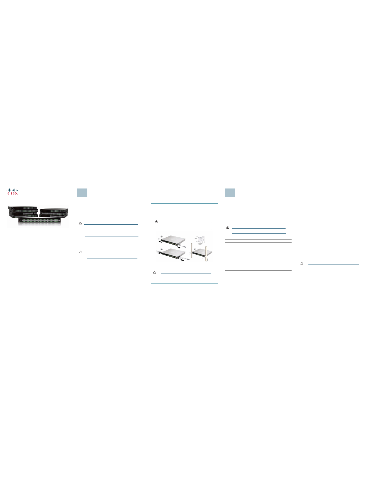
To mount the Ethernet switch, follow these instructions:
STEP1 Remove the four screws from each side of the front of the switch.
Retain the sc rews for re-ins tallation. D o not remove t he four screws
from each side of the back of the switch.
S
TEP 2 Place one of the supplied spacers on the side of the switch so the four
holes align to the screw holes. Place a rack mount bracket next to the
spacer and reinstall the four screws removed in step 1.
NOTE If your screws are not long enough to reattach the bracket with
the spacer in place, attach the bracket directly to the case
without the spacer.
STEP 3 After the mounting hardware has been securely attached, the switch
is now ready to be installed into a standard 19-inch rack as shown.
!
CAUTION For stability, load the rack from the bottom to the top, with
the heaviest devices on the bottom. A top-heavy rack is
likely to be unstable and may tip over.
Getting to Know the Switch
This guide covers the following products:
• SFE2000/P
• SGE2000/P
• SFE2010/P
• SGE2010/P
Switch Ports and LEDs
The LEDs and network ports are located on the front panel of the switch. Refer
to the Port Descriptions table, for details on port functionality.
NOTE The P in the model name indicates that the switch provides
Power over Ethernet (PoE) to connected devices.
Port Descriptions
Port Description
Switch Ports The switch is equipped with auto-sensing, Ethernet (802.3)
network ports which use RJ-45 connectors. The Ethernet
ports support network speeds of 10 Mbps, 100 Mbps, or
1000 Mbps. They can operate in half-duplex and full-duplex
modes. Auto-sensing technology enables each port to
automatically detect the speed and duplex mode of a
connected device, and to adjust both accordingly. These
ports are typically used for devices such as PCs, servers, IP
phones and Access Points.
Uplink Ports These ports are typically used for connecting to other
switches, routers, or network backbone devices. The miniGBIC ports are considered uplink ports.
mini-GBIC
Ports
The mini-GBIC (Gigabit Interface Converter) port is a
connection point for a mini-GBIC expansion module, allowing
the switch to be uplinked via fiber to another switch. Each
mini-GBIC port provides a link to a high-speed network
segment or individual workstation at speeds of up to 1000
Mbps.
2
Port LEDs
LINK/ACT—Each green LED lights up when a connection is made through its
corresponding port. It flashes when the corresponding port is active.
SPEED—On non-PoE switches, a green LED indicates that the port is operating
at the maximum speed (Fast Ethernet or Gigabit Ethernet).
PoE—On PoE switches, a green LED indicates that PoE is active on that port.
The switch can deliver a maximum of 15.4 Watts to a PoE port. See the
SFE/
SGE Managed Switch
Administration Guide
for platform PoE power limitations.
Switch LEDs
PWR—A green LED lights up and remains lit when the switch is powered on.
FAN— A green LED lights up to indicate that the cooling fan is operating
properly. A flashing red LED indicates that the cooling fan has failed.
RPS—A green LED lights up to indicate that RPS is connected and operating
properly. A flashing red LED indicates an RPS fault.
MST—A green LED indicates that this switch is a stack master.
Stack ID—A green LED indicates that this switch is stacked and the
corresponding number indicates its stack ID.
Other Features
Reset—The switch can be reset by inserting a pin or paper clip into the RESET
opening.
RPS—A connector for a Redundant Power Supply is located on the back of the
switch.
Power—The Power port is where you will connect the power cord.
Console—The Console port is where you can connect a serial cable to a PC’s
serial port for configuration using a terminal emulation program.
!
CAUTION If the RESET switch is pressed for more than 10 seconds,
the switch will reset to its default settings. All c ustomized
user settings will be lost .
Page 2
Americas Headquarters
Cisco Systems, Inc.
170 West Tasman Drive
San Jose, CA 95134-1706
USA
http://www.cisco.com
Tel: 408 526-4000
800 553-NETS (6387)
Fax:408 527-0883
Cisco, Cisco Systems, the Cisco logo, and the Cisco Systems logo are registered trademarks or
trademarks of CiscoSyst ems, Inc. and/or its affiliates in the UnitedStates and certain other
countries. All other trademarks mentioned in this document or Website are the property of their
respective owners. The use of the word partner does not imply a partnership relationship
between Cisco and any other company. (0705R)
© 2009 Cisco Systems, Inc. All rights reserved.
Printed in the USA on recycled paper containing 10% postconsumer waste.
78-19143-01
Stacking the Switches
Before setting up stacked switches in your network, see the
Managing Stacking
chapter in the
SFE/SGE Managed Switch Administration Guide
.
Switches can operate in two different modes, Stack mode and Stand-Alone
mode. In Stack mode, a switch operates as a member of an organized group of
switches known as a stack. A stack consists of one Stack Master control switch,
one Master Backup switch and Stack Member switches. A total of 192 ports can
be integrated in a stack. You cannot mix GE and FE switches in a stack.
NOTE By default, a switch is in stack mode and the Unit ID
assignment is Auto. A stacking port functions as a regular
ethernet port when the switch is in Stand-Alone mode, or if
it is replaced by another stacking port through configuration
3
The following table shows the default stacking ports and the configurable
stacking ports:
If you manually assign a Unit ID to one unit, you should manually assign Unit IDs
to
all
units. Using both system-assigned and manually-assigned IDs in your
network can impact system performance.
Changing the stacking mode of a switch requires a reboot of the switch.
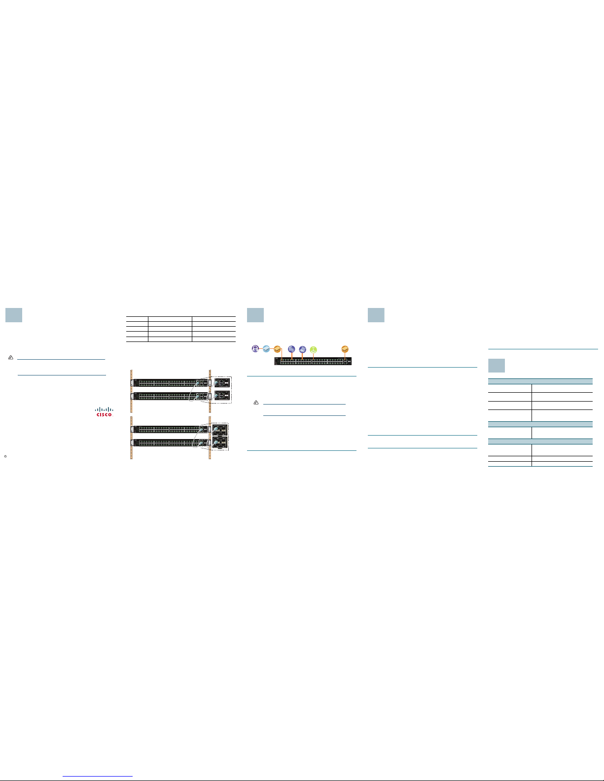
The following diagrams illustrate the SFE and the SGE devices in a stack:
Model Default Stacking Port Configurable Stacking Port
SFE2000 G1, G2 G3/GBIC1, G4/GBIC 2
SGE2000 12/GBIC 3, 24/GBIC 4 N/A
SFE2010 G1, G2 GBIC 1, GBIC 2
SGE2010 24/GBIC 3, 48/GBIC4 N/A
180778
181055
Connecting Devices
For an example of a possible network configuration, see the application
diagram shown below.
Perform the steps in this section to connect devices to the switch.
STEP1 Connect devices such as a PC, IP Phone, Access Point, or a Server
to one of the numbered ports on the switch using an Ethernet cable.
S
TEP 2 Connect uplink devices, such as a Cisco Small Business RV082,
WRVS4400N, or another type of router to one of the uplink ports on the
switch using an Ethernet cable.
NOTE Cisco strongly recommends using Cat5E or better cable. When
you connect your network devices, make sure you don’t exceed
the maximum cabling distance of 100 meters (328 feet).
STEP 3 If you are using the mini-GBIC port, insert the mini-GBIC module to the
mini-GBIC port. For more instructions about the mini-GBIC module,
see the instructions that came with the module.
S
TEP 4 If required, power on the devices connected to the switch. The
corresponding LED for each active port will light up on the switch.
S
TEP 5 You are now ready to begin configuring the switch. For details, refer to
the
SFE/SGE Managed Switch Administration Guide
.
4
Internet Router Notebook Router
Cable/
DSL Modem
10/100/1000
Desktop
Wireless
Access Point
194624
Getting Started with the
Configuration
This section contains information for starting to provision the switch features.
The switch can be configured in three ways — over IP using the embedded
Web GUI, over IP using Telnet (simple configuration and diagnostics), and using
the console port.
The default static IP address is 192.168.1.254 and the default management
VLAN for the static IP address is VLAN 1. The default user name is
admin
and
the default password is
admin
.
To configure the switch over IP with Web GUI and Telnet:
STEP1 Connect a PC to any of the non-stacking ethernet ports with an
Ethernet cable.
S
TEP 2 Open a web browser. Cisco recommends Internet Explorer version 7
or later, or FireFox version 3. If you are prompted to install an Active-X
plugin when connecting to the switch, follow the prompts to accept the
plugin.
S
TEP 3 Enter the IP address of the switch in the address bar and press Enter.
For example, if the switch is using the default IP address, enter http://
192.168.1.254. The
Login Page
opens.
S
TEP 4 Enter a user name and password. Passwords are both case sensitive
and alpha-numeric.
S
TEP 5 Click Login. The
Switch Configuration Utility System Dashboard
Window appea rs.
You are now ready to configure the switch. Refer to the
SFE/SGE
Managed Switch Administration Guide
for further information.
To configure the switch by using the console port:
STEP1 Connect a PC to the switch console port using the console port
cable provided.
S
TEP 2 Start a console port utility such as HyperTerminal on the PC.
S
TEP 3 Configure the utility with the following parameters:
5
• 115200 bits per second
• 8 data bits
• no parity
• 1 stop bit
• no flow control
S
TEP 4 Enter a user name and password. Passwords are both case sensitive
and alpha-numeric.
You are now ready to configure the switch. Refer to the
SFE/SGE
Managed Switch Administration Guide
for further information.
Where to Go From here
Support
Cisco Small Business Support
Community
www.cisco.com/go/smallbizsupport
Online Technical Support and
Documentation (Login Required)
www.cisco.com/support
Phone Support Contacts www.cisco.com/en/US/support/tsd_cisco_
small_business_support_center_contacts.html
Software Downloads
(Login Required)
Go to tools.cisco.com/support/downloads,
and enter the model number in the Software
Search box.
Product Documentation
Cisco Small Business Series
Smart Gigabit Ethernet Switch
Documentation
www.cisco.com/en/US/products/ps9967/
tsd_products_support_series_home.h tml
Cisco Small Business
Cisco Partner Central for Small
Business (Partner Login
Required)
www.cisco.com/web/partners/sell/smb
Cisco Small Business Home www.cisco.com/smb
Marketplace www.cisco.com/go/marketplace
6
 Loading...