

Page 1
Quick Start Guide
Guía de inicio rápido
Guide de démarrage rapide
Cisco 350 Series Managed Switches
Switches administrados Cisco serie 350
Commutateurs administrables Cisco 350
Page 2

Welcome
1
Thank you for choosing the Cisco 350 Series Managed Switches. The
switches are designed to be operational right out-of-the-box as standard
layer 2 and 3 switches. Using the default configuration, your switch
forwards packets between the connecting devices after power up.
This guide familiarizes you with the switch layout and describes how to
deploy the switch in your network. For additional information, see
www.cisco.com/go/350switches.
Package Contents
• Your Cisco 350 Series Managed Switch
• Power Cord
• Rack-Mount Kit and Rubber Feet
• Wall Mounting Package for SF352-08, SF352-08MP, SF352-08P,
SG350-10, SG350-10P, SG350-10MP, or SG350-10SFP
• DB-9 to RJ45 Serial Cable
• Quick Start Guide
• Pointer Card with China RoHS
• Technical Support Contacts
• EU Directives 1999/5/EC Compliance Information (for EU SKU only)
Before You Begin
Before you begin the installation, make sure that you have the following:
• Category 5e or higher RJ-45 Ethernet cables for connecting network
devices.
• Console cable for using the console port to manage your switch.
• Tools for installing the hardware. The rack-mount kit packed with the
switch contains four rubber feet for desktop placement, and two
brackets and twelve screws for rack-mounting. If the supplied screws
are lost, use replacement screws in the following size:
– Diameter of the screw head: 6.9 mm
– Length of face of screw head to base of screw: 5.9 mm
– Shaft diameter: 3.94 mm
• The wall mount kit includes screws and anchors. If the supplied screws
are lost, use replacement screws in the following size:
2 Cisco 350 Series Managed Switches
Page 3

– Diameter of the screw head: 6.8 mm
2
– Length of face of screw head to base of screw: 16 mm
– Shaft diameter: 3.5 x 1.3 mm
• Computer with Microsoft Internet Explorer (version 9.0, 10.0, 11.0),
Mozilla Firefox (version 51.0, 52.0, 53.0, or higher), or Google Chrome
(version 56, 57, 58, or higher) for using the web-based interface or the
console port to manage your switch.
Mounting the Cisco 350 Series Switches
Depending on your switch, there are two or three ways to install the switch:
• Place the switch on a flat surface. To place the switch on a desktop,
install the four rubber feet (included) on the bottom of the switch.
• Mount the switch in a standard rack (1 rack unit high).
• Many of the 350 Series Cisco switches include wall-mounting slots on
the bottom of the device.
Placement Tips
Do not deploy the switch in a location where any of the following
conditions exist:
•Ambient Temperature—To prevent the switch from overheating, do not
operate it in an area that exceeds an ambient temperature of 122°F
(50°C).
•Air Flow—Be sure that there is adequate air flow around the switch.
• Mechanical Loading—Be sure that the switch is level and stable to
avoid any hazardous conditions.
• Circuit Overloading—Adding the switch to the power outlet must not
overload that circuit.
Rack Mounting
You can mount the switches in any standard size, 19-inch (about 48 cm)
wide rack. The switch requires 1 rack unit (RU) of space, which is 1.75
inches (44.45 mm) high.
CAUTION For stability, load the rack from the bottom to the top, with the
heaviest devices on the bottom. A top-heavy rack is likely to
be unstable and might tip over.
Cisco 350 Series Managed Switches 3
Page 4

To install the switch into a 19-inch standard chassis:
400925
STEP 1 Place one of the supplied brackets on the side of the switch so that
the four holes of the brackets align to the screw holes, and then use
the four supplied screws to secure it.
STEP 2 Repeat the previous step to attach the other bracket to the opposite
side of the switch.
STEP 3 After the brackets are securely attached, the switch is now ready
to be installed into a standard 19-inch rack.
Wall Mounting
Most of the 350 Series Cisco switches include wall-mounting slots on the
bottom of the device.
WARNING Insecure mounting may damage the device or cause injury.
Cisco is not responsible for damages incurred by insecure wall
or ceiling mounting.
To mount your switch to a wall:
STEP 1 Determine where you want to mount the device. Verify that the
surface is smooth, flat, dry, and sturdy.
STEP 2 Drill two pilot holes into the surface of the wall 94 mm apart.
STEP 3 Insert a screw into each hole, leaving a gap between the surface
and the base of the screw head.
4 Cisco 350 Series Managed Switches
Page 5
TEP 4 Place the bottom of the switch over the screws and slide the
3
S
switch down until the screws fit snugly into the slots.
Connecting Network Devices
To connect the switch to the network:
STEP 1 Connect an Ethernet cable to the Ethernet port of a computer,
printer, network storage, or other network devices.
STEP 2 Connect the other end of the Ethernet cable to one of the
numbered Ethernet ports of the switch.
The Ethernet port light turns green when the connection is active.
Refer to Cisco 350 Series Switch Features for details about the
different ports and LEDs on each switch.
STEP 3 Repeat Step 1 and Step 2 for each device that you want to
connect to the switch.
NOTE A category 5e and higher cable is required for all ports. When you
connect your network devices, do not exceed the maximum cabling
distance of 100 meters (328 feet). It can take up to one minute for the
attached devices or the LAN to be operational after it is connected. This
behavior is normal.
Power over Ethernet Considerations
WARNING The switch is to be connected only to PoE networks without
routing to the outside plant.
If your switch is one of the Power over Ethernet (PoE) models, consider the
following power requirements:
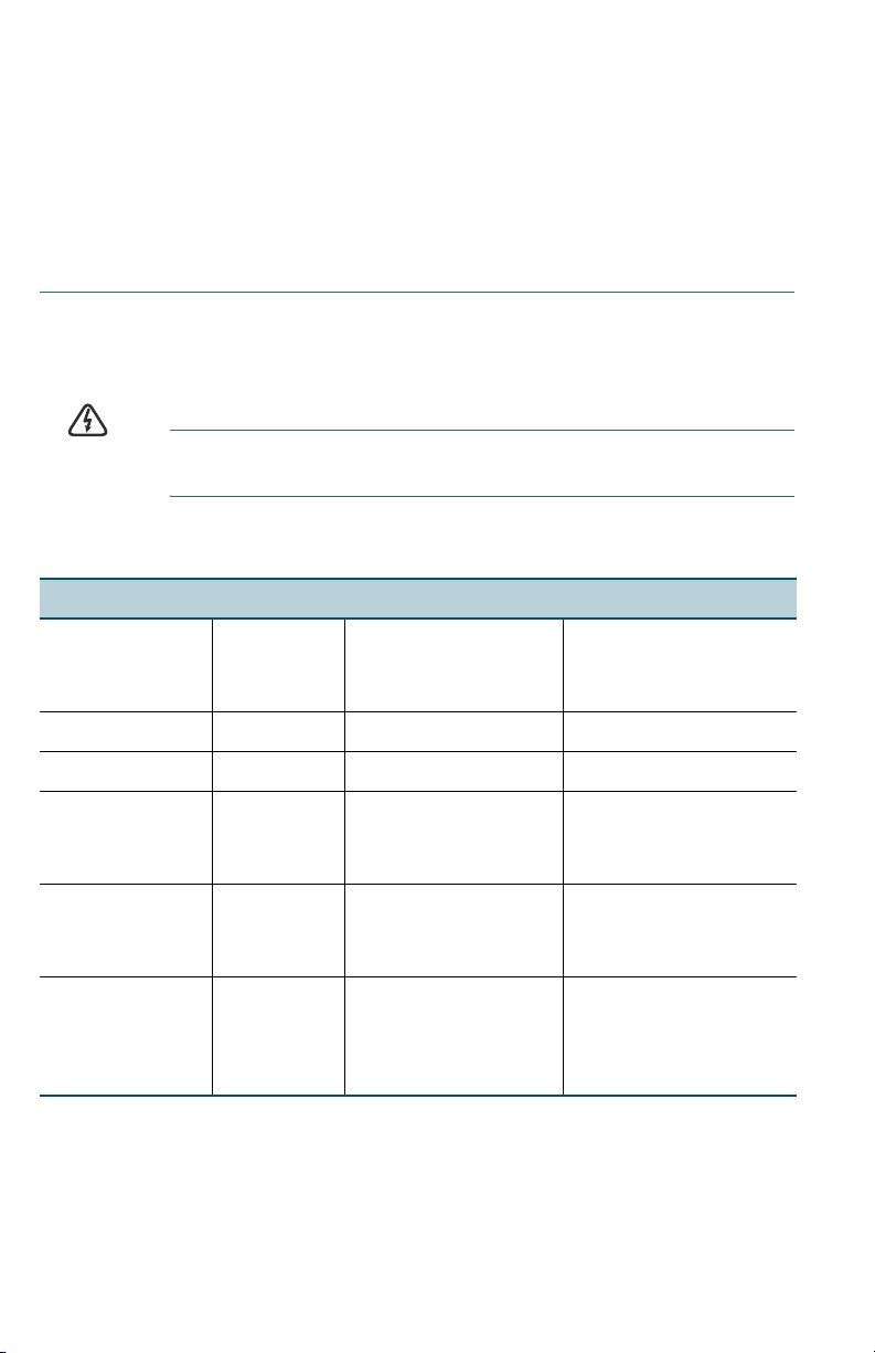
350 Switches with Power Over Ethernet
Model Power
Dedicated
to PoE
SF352-08P 62 Watts 1–8 802.3af/at
SF352-08MP 128 Watts 1–8 802.3af/at
Cisco 350 Series Managed Switches 5
Number of Ports
Supporting PoE
PoE Standard
Supported
Page 6

SF350-24P 185 Watts 1–24
*60-Watt PoE: ports
1,2,13,14
802.3af/at
4-pair PoE
SF350-24MP 375 Watts 1–24
*60-Watt PoE: ports
1,2,13,14
SF350-48P 382 Watts 1–48
*60-Watt PoE: ports
1,2,3,4,25,26,27,28
SF350-48MP 740 Watts 1–48
*60-Watt PoE: ports
1,2,3,4,25,26,27,28
802.3af/at
4-pair PoE
802.3af/at
4-pair PoE
802.3af/at
4-pair PoE
SG350-10P 62 Watts 1–8 802.3af/at
SG350-10MP 128 Watts 1–8 802.3af/at
SG355-10P 62 Watts 1–8 802.3af/at
SG350-28P 195 Watts 1–24
*60-Watt PoE: ports
1,2,13,14
SG350-28MP 382 Watts 1–24
*60-Watt PoE: ports
1,2,13,14
SG350-52P 375 Watts 1–48
*60-Watt PoE: ports
1,2,3,4,25,26,27,28
802.3af/at
4-pair PoE
802.3af/at
4-pair PoE
802.3af/at
4-pair PoE
SG350-52MP 740 Watts 1–48
*60-Watt PoE: ports
1,2,3,4,25,26,27, 28
802.3af/at
4-pair PoE
SG350-8PD 124 Watts 1–8 802.3af/at
*60-Watt PoE extends the IEEE Power over Ethernet Plus standard to
double the power per port to 60 watts.
6 Cisco 350 Series Managed Switches
Page 7

CAUTION Consider the following when connecting switches capable of
454
supplying PoE:
The PoE models of the switches are PSE (Power Sourcing
Equipment) that are capable of supplying DC power to
attaching PD (Powered Devices). These devices include VoIP
phones, IP cameras, and wireless access points. The PoE
switches can detect and supply power to pre-standard
legacy PoE Powered Devices. Due to the support of legacy
PoE, it is possible that a PoE switch acting as a PSE may
mistakenly detect and supply power to an attaching PSE,
including other PoE switches, as a legacy PD.
Even though PoE switches are PSE, and as such should be
powered by AC, they could be powered up as a legacy PD
by another PSE due to false detection. When this happens,
the PoE switch may not operate properly and may not be
able to properly supply power to its attaching PDs.
To prevent false detection, you should disable PoE on the
ports on the PoE switches that are used to connect to PSEs.
You should also first power up a PSE device before
connecting it to a PoE switch. When a device is being falsely
detected as a PD, you should disconnect the device from the
PoE port and power recycle the device with AC power
before reconnecting its PoE ports.
Configuring the 350 Series Switches
Before You Begin
The switch can be accessed and managed by two different methods; over
your IP network using the web-based interface, or by using the switch’s
command-line interface through the console port. Using the console port
requires advanced user skills.
These are the default settings used when configuring your switch for the
first time.
Parameter Default Value
Username cisco
Password cisco
LAN IP 192.168.1.254
Cisco 350 Series Managed Switches 7
Page 8

Configuring Your Switch Using the Web-based Interface
To access the switch with a web-based interface, you must know the IP
address that the switch is using. The switch uses the factory default IP
address of 192.168.1.254, with a subnet of /24.
When the switch is using the factory default IP address, the System LED
flashes continuously. When the switch is using a DHCP server-assigned IP
address or an administrator has configured a static IP address, the System
LED is a steady green (DHCP is enabled by default).
NOTE If you are managing the switch through a network connection and
the switch IP address is changed, either by a DHCP server or manually,
your access to the switch will be lost. You must enter the new IP address
that the switch is using into your browser to use the web-based
interface. If you are managing the switch through a console port
connection, the link is retained.
To configure the switch using the web-based interface:
STEP 1 Power on the computer and your switch.
STEP 2 Connect the computer to any network port.
STEP 3 Set up the IP configuration on your computer.
a. If the switch is using the default static IP address of
192.168.1.254/24, you must choose an IP address for the
computer in the range of 192.168.1.2 to 192.168.1.253 that is
not already in use.
b. If the IP addresses will be assigned by DHCP, make sure that
your DHCP server is running and can be reached from the
switch and the computer. You may need to disconnect and
reconnect the devices for them to discover their new IP
addresses from the DHCP server.
NOTE Details on how to change the IP address on your computer
depend upon the type of architecture and operating system that
you are using. Use your computers local Help and Support
functionality and search for “IP Addressing.”
STEP 4 Open a web browser window. If you are prompted to install an
ActiveX plug-in when connecting to the device, follow the prompts
to accept the plug-in.
STEP 5 Enter the switch IP address in the address bar and press Enter. For
example, http://192.168.1.254.
STEP 6 When the login page appears, choose the language that you prefer
to use in the web-based interface and enter the username and
password.
8 Cisco 350 Series Managed Switches
Page 9

The default username is cisco. The default password is cisco.
Usernames and passwords are both case sensitive.
STEP 7 Click Log In.
If this is the first time that you have logged on with the default
username and password, the Change Password page opens. The
rules for constructing a new password are displayed on the page.
STEP 8 Enter a new password and confirm the password.
NOTE Password complexity is enabled by default. The password
must comply with the default complexity rules or it can be disabled
temporarily by checking Disable next to the Password Strength
Enforcement option.
STEP 9 Click Apply.
CAUTION Make sure that any configuration changes made are saved
before exiting from the web-based interface by clicking on
the Save icon. Exiting before you save your configuration
results in all changes being lost.
The Getting Started page opens. You are now ready to configure
the switch. Refer to the Administration Guide or see the help pages
for further information.
Configuring Your Switch Using the Console Port
To configure the switch using the console port:
STEP 1 Connect a computer to the switch console port using the supplied
console cable.
STEP 2 Start a console port utility such as HyperTerminal on the computer.
STEP 3 Configure the utility with the following parameters:
• 115200 bits per second
• 8 data bits
• no parity
• 1 stop bit
• no flow control
STEP 4 Enter a username and password. The default username is cisco,
and the default password is cisco. Usernames and passwords are
both case sensitive.
Cisco 350 Series Managed Switches 9
Page 10

If this is the first time that you have logged on with the default
username and password, the following message appears:
Please change your password from the default
settings. Please change the password for better
protection of your network. Do you want to change
the password (Y/N) [Y]?
STEP 5 Enter Y, and set a new administrator password.
NOTE Password complexity is enabled by default. The password
must comply with the default complexity rules.
CAUTION Make sure that any configuration changes made are saved
before exiting.
You are now ready to configure the switch. Refer to www.cisco.com/go/
350switches to locate the CLI Guide for your switch.
NOTE If you are not using DHCP on your network, set the IP address type
on the switch to Static and change the static IP address and subnet mask
to match your network topology. Failure to do so may result in multiple
switches using the same factory default IP address of 192.168.1.254.
10 Cisco 350 Series Managed Switches
Page 11

Cisco 350 Series Switch Features
5
This section describes the exterior of the switch to help familiarize you
with your switch.
Product Models
Model Description
SF350-08 8-Port 10/100 Managed Switch
SF350-24 24-Port 10/100 Managed Switch
SF350-24MP 24-Port 10/100 PoE Managed Switch
SF350-24P 24-Port 10/100 PoE Managed Switch
SF350-48 48-Port 10/100 Managed Switch
SF350-48MP 48-Port 10/100 PoE Managed Switch
SF350-48P 48-Port 10/100 PoE Managed Switch
SF352-08 8-Port 10/100 Managed Switch
SF352-08MP 8-Port 10/100 PoE Managed Switch
SF352-08P 8-Port 10/100 PoE Managed Switch
SG350-10 10-Port Gigabit Managed Switch
SG350-10MP 10-Port Gigabit PoE Managed Switch
SG350-10P 10-Port Gigabit PoE Managed Switch
SG350-10SFP 10-Port Gigabit Managed SFP Switch
SG350-20 20-Port Gigabit Managed Switch
SG350-28 28-Port Gigabit Managed Switch
SG350-28MP 28-Port Gigabit PoE Managed Switch
SG350-28P 28-Port Gigabit PoE Managed Switch
SG350-28SFP 28-Port Gigabit Managed SFP Switch
SG350-52 52-Port Gigabit Managed Switch
SG350-52P 52-Port Gigabit PoE Managed Switch
SG350-52MP 52-Port Gigabit PoE Managed Switch
SG355-10P 10-Port Gigabit PoE Managed Switch
SG350-8PD 8-Port 2.5G PoE Managed Switch
Cisco 350 Series Managed Switches 11
Page 12

Front Panel
The ports, LEDs, and Reset button are located on the front panel of the
switch as represented in the following illustrations.
SF350-48MP
SG350-8PD
SG355-10P
Front Panel Ports
USB Port—The USB port connects the switch to a USB device so that you
can save and restore the configuration files, firmware images, and
SYSLOG files through the connected USB device.
RJ-45 Ethernet Ports—The RJ-45 Ethernet ports connect network devices,
such as computers, printers, and access points, to the switch.
Multigigabit Ethernet Ports—Highlighted in blue, these ports support
speeds of 100 Mbps, 1 Gbps, and 2.5 Gbps, on Cat 5e cables. Much of the
cabling deployed worldwide is limited to 1 Gbps at 100 meters. Cisco
Multigigabit Ethernet enables speeds up to 2.5 Gbps on the same
infrastructure without replacing a cable.
60-Watt PoE Ports—Highlighted in yellow, the 60-Watt PoE ports double
the PoE power to 60W.
SFP Port (if present)—The small form-factor pluggable (SFP) ports are
connection points for modules, so the switch can link to other switches.
These ports are also commonly referred to as miniGigaBit Interface
Converter (miniGBIC) ports. The term SFP is used in this guide.
• Some SFP interfaces are shared with one other RJ-45 port, called a
combo port. When the SFP is active, the adjacent RJ-45 port is
disabled.
• The LEDs of the corresponding RJ-45 port flash green to respond to the
SFP interface traffic.
12 Cisco 350 Series Managed Switches
Page 13
Front Panel LEDs
400924
6
System—(Green) The LED lights steady when the switch is powered on,
and flashes when booting, performing self-tests, or acquiring an IP
address. If the LED flashes Amber, the switch has detected a hardware
failure, a firmware failure, and/or a configuration file error.
LINK/ACT—(Green) Located on the left of each port. The LED lights steady
when a link between the corresponding port and another device is
detected, and flashes when the port is passing traffic.
Gigabit—(Green) Located on the right of the port. The LED lights steady
when another device is connected to the port, is powered on, and a 1000
Mbps link is established between the devices. When the LED is off, the
connection speed is under 1000 Mbps or nothing is cabled to the port.
PoE (if present)—(Amber) Located on the right of the port. The LED lights
steady when power is being supplied to a device attached to the
corresponding port.
Reset Button
The switch can be reset by inserting a pin or paper clip into the Reset
button opening on the front panel of the switch. See Returning the
Switches to the Factory Default Settings for details.
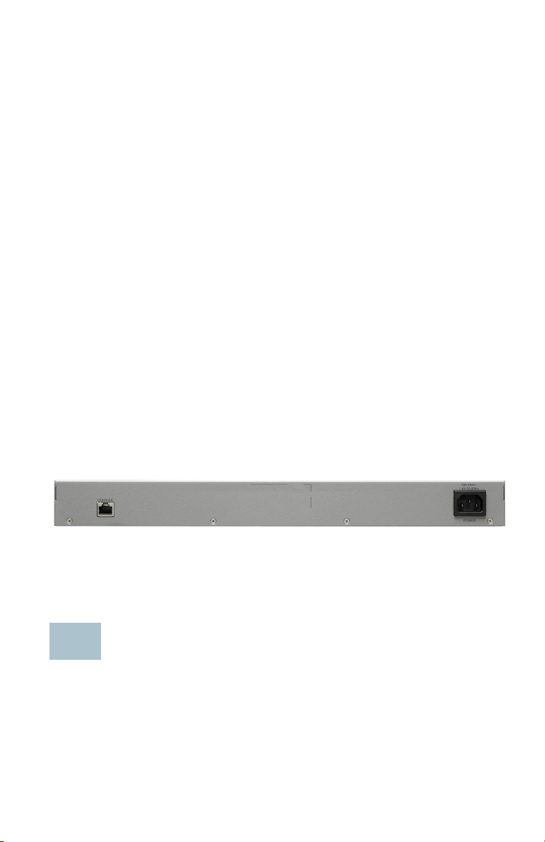
Back Panel
The power port and console port are located on the back panel of the
switch. The back panel of your particular switch may look different, and if
your model has a fan, allow for adequate air circulation.
Power—Connects the switch to AC power.
Console—Connects a serial cable to a computer serial port so that it can
be configured by using a terminal emulation program.
Returning the Switches to the Factory Default Settings
To use the Reset button to reboot or reset the switch, do the following:
• To reboot the switch, press and hold the Reset button for less than ten
seconds.
• To restore the switch to its factory default settings:
Cisco 350 Series Managed Switches 13
Page 14

– Disconnect the switch from the network or disable all DHCP
servers on your network.
– With the power on, press and hold the Reset button for more than
ten seconds.
Troubleshoot Your Connection
If you cannot access your switch from the web-based interface, the switch
may not be reachable from your computer. You can test network
connections by using ping on a computer running Windows:
STEP 1 Open a command window by selecting Start > Run and enter cmd.
STEP 2 At the Command window prompt, enter ping and the switch IP
address. For example, ping 192.168.1.254 (the default static IP
address of the switch).
If you can reach the switch, you should get a reply similar to the
following:
Pinging 192.168.1.254 with 32 bytes of data:
Reply from 192.168.1.254:bytes=32 time<1ms TTL=128
If you cannot reach the switch, you should get a reply similar to the
following:
Pinging 192.168.1.254 with 32 bytes of data:
Request timed out.
Possible Causes and Resolutions
The Switch is not Powering on
• Verify the power cord is plugged firmly into the switch and into the
power outlet.
• Verify that the power outlet is active.
• Verify that the computer is on.
• Replace the power adapter, before replacing the switch, if the situation
continues.
Bad Ethernet connection
• Check the LEDs for proper indications. See Front Panel for details.
• Check the connectors of the Ethernet cable to ensure that they are
firmly plugged into the switch and your computer.
• Use a different Ethernet cable or port.
Bad Console port connection
14 Cisco 350 Series Managed Switches
Page 15

• Verify the console cable connectors are firmly plugged into the switch
and your computer.
• Verify the console port utility is configured with the correct parameters.
IP Addressing Issues
• The Cisco switches can also be accessed by the Cisco FindIT Network
Discovery Utility that automatically discovers all Cisco Small
Business devices in the same local network segment as your computer.
You can view device information including the current IP address,
download the latest firmware for the device, or launch the product
configuration utility to view and configure the settings. For more
information, see www.cisco.com/go/findit.
• Verify that you are using the correct IP address of the switch. Determine
the current IP address of the switch from the CLI through the console
port, Cisco FindIT, or from your network administrator. The System LED
provides an indication of where the switch received the IP address (See
Front Panel for details.)
• Make sure that no other device is using the same IP address as the
switch.
No IP route
If the switch and your computer are in different IP subnets, you need
one or more routers to route the packets between the two subnets.
Unusually long access time
Due to the standard spanning tree loop detection logic, adding new
connections may take 30 to 60 seconds for the affected interfaces
and/or LAN to become operational.
Cisco 350 Series Managed Switches 15
Page 16
Where to Go From Here
7
Cisco Support Community www.cisco.com/go/smallbizsupport
Cisco Support and
Resources
Phone Support Contacts www.cisco.com/en/US/support/
Cisco Firmware Downloads www.cisco.com/go/smallbizfirmware
Cisco Open Source
Requests
Cisco Partner Central
(Partner Login Required)
www.cisco.com/go/smallbizhelp
tsd_cisco_small_business
_support_center_contacts.html
Select a link to download firmware for
Cisco Products. No login is required.
To receive a copy of the source code to
which you are entitled under the applicable
free/open source license(s) (such as the
GNU Lesser/General Public License),
please send your request to:
externalopensource-requests@cisco.com
In your requests please include the Cisco
product name, version, and the 18 digit
reference number (for example:
7XEEX17D99-3X49X081) found in the
product open source documentation.
www.cisco.com/web/partners/sell/smb
Product Documentation
350 Series www.cisco.com/go/350switches
Regulatory Compliance
and Safety Information
Warranty Information www.cisco-warrantyfinder.com
WARNING This is a class A product. In a domestic environment this
product may cause radio interference in which case the user
may be required to take adequate measures.
16 Cisco 350 Series Managed Switches
www.cisco.com /en/US /docs/switches/lan/
csb_switching_general/rcsi/
Switch_RCSI.pdf
Page 17

Cisco 350 Series Managed Switches 17
Page 18
Americas Headquarters
Cisco Systems, Inc.
www.cisco.com
Cisco has more than 200 offices worldwide.
Addresses, phone numbers, and fax numbers
are listed on the Cisco website at
www.cisco.com/go/offices.
Cisco and the Cisco logo are trademarks or registered trademarks of Cisco and/or its affiliates
78-101212-01A0
in the U.S. and other countries. To view a list of Ciscotrademarks, go to this URL:
www.cisco.com/go/trademarks. Third-party trademarks mentioned are the property of their
respective owners. The use of the word partner does not imply a partnership relationship
between Cisco and any other company. (1110R)
© 2017 Cisco Systems, Inc. All rights reserved.
Page 19

Guía de inicio rápido
Switches administrados Cisco serie 350
Page 20

Bienvenido
1
Gracias por elegir los switches administrados Cisco de la serie 350. Estos
switches se diseñaron y configuraron de fábrica para funcionar como
switches estándares de capa 2 y 3. En la configuración predeterminada,
su switch reenvía paquetes entre los dispositivos de conexión tras el
encendido.
Esta guía le permite familiarizarse con la disposición del switch y en ella
se describe cómo implementar el switch en su red. Para obtener más
información, visite www.cisco.com/go/350switches.
Contenido del paquete
• Switch administrado Cisco serie 350
• Cable de alimentación eléctrica
• Kit de montaje en rack y pies de goma
• Paquete de montaje en pared para SF352-08, SF352-08MP, SF352-
08P, SG350-10, SG350-10P, SG350-10MP o SG350-10SFP
• Cable serial DB-9 a RJ45
• Guía de inicio rápido
• Tarjeta informativa con RoHS de China
• Contactos de soporte técnico
• Información de cumplimiento de las directivas de la Unión Europea
1999/5/EC (para las SKU de la UE únicamente)
Antes de empezar
Antes de comenzar la instalación, asegúrese de contar con lo siguiente:
• Cables Ethernet RJ-45 de categoría 5e o superior para conectar los
dispositivos de red.
• Cable de la consola para usar el puerto de la consola para administrar
el switch.
20 Switches administrados Cisco serie 350
Page 21

• Herramientas para instalar el hardware. El kit de montaje en rack que
2
viene con el switch contiene cuatro pies de goma para ubicar la unidad
sobre el escritorio, y dos soportes y doce tornillos para montaje en
rack. Si los tornillos provistos se pierden, use tornillos de reemplazo del
siguiente tamaño:
– Diámetro de la cabeza del tornillo: 6,9 mm
– Longitud de la cara de la cabeza del tornillo a su base: 5,9 mm
– Diámetro del eje: 3,94 mm
• El kit de montaje en pared incluye tornillos y anclas. Si los tornillos
provistos se pierden, use tornillos de reemplazo del siguiente tamaño:
– Diámetro de la cabeza del tornillo: 6,8 mm
– Longitud de la cara de la cabeza del tornillo a su base: 16 mm
– Diámetro del eje: 3,5 x 1,3 mm
• Equipo con Microsoft Internet Explorer (versión 9.0, 10.0, 11.0), Mozilla
Firefox (versión 51.0, 52.0, 53.0 o superior) o Google Chrome (versión
56, 57, 58 o superior) para usar la interfaz basada en la Web o el puerto
de la consola para administrar el switch.
Montaje de los switches Cisco Serie 350
En función de cuál sea su switch, hay dos o tres formas de instalarlo:
• Colocar el switch sobre una superficie plana. Para colocar el switch
en un escritorio, instale los cuatro pies de goma (incluidos) en la parte
interior del switch.
• Instalar el switch montado en un bastidor estándar (una unidad de
bastidor de alto).
• Muchos de los switches Cisco de la serie 350 incluyen ranuras para
montaje en pared en la parte inferior del dispositivo.
Consejos para la colocación
No implemente el switch en una ubicación donde exista alguna de las
siguientes condiciones:
• Temperatura ambiente: para evitar que el switch se recaliente, no lo
haga funcionar en un área donde la temperatura ambiente supere los
122 °F (50 °C).
• Circulación de aire: asegúrese de que la circulación de aire alrededor
del switch sea adecuada.
Switches administrados Cisco serie 350 21
Page 22

• Cargas mecánicas: asegúrese de que el switch esté nivelado y estable
400925
para evitar situaciones peligrosas.
•Sobrecarga del circuito: al conectar el switch a la toma de corriente, el
circuito no debe sobrecargarse.
Montaje en rack
Puede montar los switches en cualquier rack de tamaño estándar, de 19 in
(aproximadamente 48 cm) de ancho. El switch requiere 1 unidad de rack
(RU) de espacio, que es igual a 1,75 in (44,45 mm) de alto.
PRECAUCIÓN Para mayor estabilidad, cargue el bastidor desde abajo
hacia arriba con los dispositivos más pesados en la parte
inferior. Si coloca un bastidor con mucho peso en la parte
superior es probable que se desestabilice y se caiga.
Para instalar el switch en un chasis estándar de 19 in:
PASO 1 Coloque uno de los soportes provistos en el lateral del switch de
modo que los cuatro orificios de los soportes se alineen con los
orificios de los tornillos y, luego, use los cuatro tornillos provistos
para asegurarlo.
PASO 2 Repita el paso anterior para conectar el otro soporte en el lado
opuesto del switch.
PASO 3 Después de fijar los soportes en forma segura, el switch estará
listo para instalarse en un rack estándar de 19 in.
22 Switches administrados Cisco serie 350
Page 23

Montaje en pared
3
La mayoría de los switches Cisco de la serie 350 incluyen ranuras para
montaje en pared en la parte inferior del dispositivo.
ADVERTENCIA Un montaje poco firme puede dañar el dispositivo o
provocar lesiones. Cisco no se responsabiliza por los daños
ocasionados por un montaje inseguro en la pared o el techo.
Para montar el switch en una pared:
PASO 1 Decida en qué sitio desea instalar el dispositivo. Compruebe si la
superficie es lisa, plana, maciza y está seca.
PASO 2 Perfore dos orificios guía en la superficie de la pared a 94 mm de
distancia entre sí.
PASO 3 Inserte un tornillo en cada orificio y deje un espacio entre la
superficie y la base de la cabeza del tornillo.
PASO 4 Coloque la parte inferior del switch sobre los tornillos y deslice el
switch hacia abajo hasta que los tornillos queden firmes dentro de
las ranuras.
Conexión de los dispositivos de red
Para conectar el switch a la red:
PASO 1 Conecte el cable Ethernet al puerto Ethernet de una computadora,
impresora, red de almacenamiento u otros dispositivos de red.
PASO 2 Conecte el otro extremo del cable Ethernet a uno de los puertos
Ethernet numerados del switch.
La luz del puerto Ethernet se ilumina de color verde cuando la
conexión está activa. Consulte Funciones de los switches Cisco
Serie 350 para obtener más información sobre los distintos
puertos e indicadores LED de cada switch.
PASO 3 Repita el Paso 1 y el Paso 2 para cada dispositivo que quiera
conectar al switch.
Switches administrados Cisco serie 350 23
Page 24

N
OTA Se requiere un cable de categoría 5e y superior para todos los
puertos. Al conectar los dispositivos de red, no exceda la distancia
de cableado máxima de 328 ft (100 m). Los dispositivos o la red LAN
pueden tardar hasta un minuto en funcionar después de ser conectados.
Este comportamiento es normal.
Consideraciones de la alimentación por Ethernet
ADVERTENCIA El switch deberá estar conectado solamente a las redes
PoE sin enrutamiento a la planta externa.
Si el switch es uno de los modelos de alimentación por Ethernet (PoE),
tenga en cuenta los siguientes requisitos de alimentación:
Switches de la serie 350 con alimentación a través de Ethernet
Modelo Energía
dedicada
a PoE
Cantidad de
puertos
compatibles con
Compatibilidad con
estándar PoE
PoE
SF352-08P 62 vatios 1-8 802.3af/at
SF352-08MP 128 vatios 1-8 802.3af/at
SF350-24P 185 vatios 1–24
*PoE de 60 vatios:
puertos 1, 2, 13, 14
SF350-24MP 375 vatios 1–24
*PoE de 60 vatios:
puertos 1, 2, 13, 14
SF350-48P 382 vatios 1–48
*PoE de 60 vatios:
puertos 1, 2, 3, 4,
802.3af/at
4-pair PoE
802.3af/at
4-pair PoE
802.3af/at
4-pair PoE
25, 26, 27, 28
SF350-48MP 740 vatios 1–48
*PoE de 60 vatios:
puertos 1, 2, 3, 4,
802.3af/at
4-pair PoE
25, 26, 27, 28
SG350-10P 62 vatios 1-8 802.3af/at
SG350-10MP 128 vatios 1-8 802.3af/at
SG355-10P 62 vatios 1-8 802.3af/at
24 Switches administrados Cisco serie 350
Page 25

Switches de la serie 350 con alimentación a través de Ethernet
Modelo Energía
dedicada
a PoE
Cantidad de
puertos
compatibles con
Compatibilidad con
estándar PoE
PoE
SG350-28P 195 vatios 1–24
*PoE de 60 vatios:
puertos 1, 2, 13, 14
SG350-28MP 382 vatios 1–24
*PoE de 60 vatios:
puertos 1, 2, 13, 14
SG350-52P 375 vatios 1–48
*PoE de 60 vatios:
puertos 1, 2, 3, 4,
802.3af/at
4-pair PoE
802.3af/at
4-pair PoE
802.3af/at
4-pair PoE
25, 26, 27, 28
SG350-52MP 740 vatios 1–48
*PoE de 60 vatios:
puertos 1, 2, 3, 4,
802.3af/at
4-pair PoE
25, 26, 27, 28
SG350-8PD 124 vatios 1-8 802.3af/at
*PoE de 60 vatios extiende la norma de alimentación por Ethernet Plus
para duplicar la alimentación por puerto a 60 vatios.
Switches administrados Cisco serie 350 25
Page 26

PRECAUCIÓN Considere lo siguiente al conectar switches capaces de
45
4
suministrar PoE:
Los modelos PoE de los switches son PSE (equipos
de fuente de alimentación) capaces de suministrar
alimentación eléctrica de CC a los PD conectados
(dispositivos alimentados). Entre estos dispositivos se
incluyen los teléfonos VoIP, las cámaras IP y los puntos de
acceso inalámbrico. Los switches PoE pueden detectar y
suministrar energía a dispositivos alimentados por PoE
heredado preestándar. Debido a la compatibilidad con la
PoE heredada, es posible que un switch PoE que actúa
como PSE sea detectado por error y suministre energía a
un PSE conectado, incluidos otros switches PoE, como un
PD heredado.
A pesar de que los switches PoE son PSE, y como tales
deberían ser alimentados por CA, pueden recibir
alimentación como PD heredados a través de otro PSE
por detección falsa. Cuando ocurre esto, es posible que
el switch PoE no funcione correctamente y que pueda
suministrar energía correctamente a sus PD conectados.
Para evitar una detección falsa, debe desconectar PoE
en los puertos de los switches PoE que se utilizan para
conectar los PSE. También puede encender primero un
dispositivo PSE antes de conectarlo al switch PoE.
Cuando se detecta un dispositivo, de manera falsa, como
un PD, debe desconectar el dispositivo del puerto PoE y
reciclar la energía del dispositivo con alimentación de CA
antes de reconectar los puertos PoE.
Configuración de los switches Serie 350
Antes de empezar
Existen dos métodos para obtener acceso al switch y administrarlo: a
través de la red IP mediante la interfaz basada en la Web, o con la interfaz
de línea de comandos del switch a través del puerto de la consola. Para
usar el puerto de la consola se requieren habilidades de usuario avanzado.
26 Switches administrados Cisco serie 350
Page 27

Estos son los parámetros predeterminados que se usan al configurar el
switch por primera vez.
Parámetro Valor predeterminado
Nombre de usuario cisco
Contraseña cisco
IP de LAN 192.168.1.254
Configuración del switch con la interfaz basada en la Web
Para obtener acceso al switch con una interfaz basada en la Web, deberá
conocer la dirección IP que el switch está utilizando. El switch usa la
dirección IP predeterminada de fábrica de 192.168.1.254, con una subred
de /24.
Si el switch usa la dirección IP predeterminada de fábrica, el indicador LED
de System (Sistema) parpadea continuamente. Cuando el switch usa una
dirección IP asignada por el servidor DHCP o una dirección IP estática
configurada por el administrador, el indicador LED del sistema permanece
encendido de color verde (DHCP está habilitado de forma
predeterminada).
NOTA Si administra el switch a través de una conexión de red y se
cambia la dirección IP del switch, ya sea mediante el servidor DHCP
o manualmente, usted perderá acceso al switch. Debe ingresar en el
explorador la nueva dirección IP que el switch está utilizando para
utilizar la interfaz basada en la Web. Si administra el switch a través
de una conexión del puerto de la consola, se conserva el enlace.
Para configurar el switch con la interfaz basada en la Web:
PASO 1 Encienda la computadora y el switch.
PASO 2 Conecte la computadora a cualquier puerto de red.
PASO 3 Establezca la configuración IP en la computadora.
a. Si el switch usa la dirección IP estática predeterminada
de192.168.1.254/24, debe elegir una dirección IP para la
computadora en el intervalo de 192.168.1.2 a 192.168.1.253
que no esté en uso.
b. Si las direcciones IP se asignarán a través de DHCP,
asegúrese de que el servidor DHCP esté en funcionamiento
y que pueda acceder a él desde el switch y la computadora.
Es posible que deba desconectar y volver a conectar los
dispositivos para que detecten las nuevas direcciones IP del
servidor DHCP.
Switches administrados Cisco serie 350 27
Page 28

N
OTA La información acerca de cómo cambiar la dirección IP de
su computadora depende del tipo de arquitectura y sistema
operativo que utilice. Use la funcionalidad de Ayuda y Soporte
local de sus computadoras y busque “IP Addressing” (Asignación
de direcciones IP).
PASO 4 Abra una ventana del explorador web. Si se le solicita que instale
un complemento ActiveX al conectar el dispositivo, siga las
instrucciones para aceptar el complemento.
PASO 5 Introduzca la dirección IP del switch en la barra de direcciones y
presione Enter (Intro). Por ejemplo: http://192.168.1.254.
PASO 6 Cuando aparezca la página de inicio de sesión, elija el idioma que
prefiera usar en la interfaz basada en la Web e ingrese el nombre
de usuario y la contraseña.
El nombre de usuario predeterminado es cisco y La contraseña
predeterminada es cisco. Los nombres de usuario y las
contraseñas distinguen entre mayúsculas y minúsculas.
PASO 7 Haga clic en Iniciar sesión.
Si es la primera vez que inicia sesión con el nombre de usuario
y la contraseña predeterminados, se abre la página Change
Password (Cambiar contraseña). En la página se muestran las
reglas para crear un usuario y una contraseña nuevos.
PASO 8 Escriba una nueva contraseña y confírmela.
NOTA La opción Complejidad de la contraseña está activada de
manera predeterminada. La contraseña debe cumplir con las
reglas de complejidad predeterminadas o se puede inhabilitar
temporalmente seleccionando Disable (Deshabilitar) junto a la
opción Password Strength Enforcement (Cumplimiento de
seguridad de la contraseña).
PASO 9 Haga clic en Aplicar.
PRECAUCIÓN Asegúrese de guardar todos los cambios de
configuración que realice antes de salir de la interfaz
basada en la Web. Para ello, haga clic en el ícono Save
(Guardar). Si sale antes de guardar la configuración,
todos los cambios se pierden.
Se abre la página Getting Started (Introducción). Ahora está listo
para configurar el switch. Consulte la Guía de administración o las
páginas de ayuda para obtener más información.
28 Switches administrados Cisco serie 350
Page 29

Configuración del switch con el puerto de la consola
Para configurar el switch con el puerto de la consola:
PASO 1 Conecte una computadora al puerto de la consola del switch con
el cable de la consola suministrado.
PASO 2 Inicie una utilidad de puerto de la consola como HyperTerminal en
la computadora.
PASO 3 Configure la utilidad con los siguientes parámetros:
• 115200 bits por segundo
• 8 bits de datos
• sin paridad
• 1 bit de parada
• sin control de flujo
PASO 4 Ingrese un nombre de usuario y una contraseña. El nombre de
usuario predeterminado es cisco y la contraseña predeterminada
es cisco. Los nombres de usuario y las contraseñas distinguen
entre mayúsculas y minúsculas.
Si es la primera vez que inicia sesión con el nombre de usuario y
la contraseña predeterminados, aparece el siguiente mensaje:
Cambie la contraseña de los valores
predeterminados. Cambie la contraseña para una
mejor protección de la red. ¿Desea cambiar la
contraseña (S/N) [S]?
PASO 5 Ingrese S y establezca una nueva contraseña de administrador.
NOTA La opción Complejidad de la contraseña está activada de
manera predeterminada. La contraseña debe cumplir con las
reglas de complejidad predeterminadas.
PRECAUCIÓN Asegúrese de que los cambios de configuración se
guarden antes de salir.
Ahora está listo para configurar el switch. Consulte www.cisco.com/go/
350switches para encontrar la guía de interfaz de línea de comandos (CLI)
de su switch.
Switches administrados Cisco serie 350 29
Page 30

N
5
OTA Si no usa DHCP en la red, establezca el tipo de dirección IP en el
switch en Static (Estática) y cambie la dirección IP estática y la máscara
de subred para que coincida con la topología de red. Si esto no se
realiza, es posible que muchos switches utilicen la misma dirección IP
predeterminada de fábrica 192.168.1.254.
Funciones de los switches Cisco Serie 350
En esta sección se describe el exterior del switch para permitirle
familiarizarse con su switch.
Modelos de productos
Modelo Descripción
SF350-08 Switch administrable 10/100 de 8 puertos
SF350-24 Switch administrable 10/100 de 24 puertos
SF350-24MP Switch administrable PoE 10/100 de
24 puertos
SF350-24P Switch administrable PoE 10/100 de
24 puertos
SF350-48 Switch administrable 10/100 de 48 puertos
SF350-48MP Switch administrable PoE 10/100 de
48 puertos
SF350-48P Switch administrable PoE 10/100 de
48 puertos
SF352-08 Switch administrable 10/100 de 8 puertos
SF352-08MP Switch administrable PoE 10/100 de 8 puertos
SF352-08P Switch administrable PoE 10/100 de 8 puertos
SG350-10 Switch Gigabit administrable de 10 puertos
SG350-10MP Switch Gigabit administrable PoE de
10 puertos
SG350-10P Switch Gigabit administrable PoE de
10 puertos
SG350-10SFP Switch SFP Gigabit administrable de
10 puertos
SG350-20 Switch Gigabit administrable de 20 puertos
SG350-28 Switch Gigabit administrable de 28 puertos
SG350-28MP Switch Gigabit administrable PoE de
28 puertos
30 Switches administrados Cisco serie 350
Page 31

Modelo Descripción
SG350-28P Switch Gigabit administrable PoE de
28 puertos
SG350-28SFP Switch SFP Gigabit administrable de
28 puertos
SG350-52 Switch Gigabit administrable de 52 puertos
SG350-52P Switch Gigabit administrable PoE de
52 puertos
SG350-52MP Switch Gigabit administrable PoE de
52 puertos
SG355-10P Switch Gigabit administrable PoE de
10 puertos
SG350-8PD Switch administrable PoE 2.5G de 8 puertos
Panel frontal
Los puertos, los indicadores luminosos y el botón de reinicio se
encuentran en el panel frontal del switch, como se representa en las
siguientes ilustraciones.
SF350-48MP
SG350-8PD
SG355-10P
Puertos del panel frontal
Puerto USB: el puerto USB conecta el switch con un dispositivo USB para
que usted pueda guardar y restaurar los archivos de configuración, las
imágenes de firmware y los archivos SYSLOG a través del dispositivo USB
conectado.
Puertos Ethernet RJ-45: los puertos Ethernet RJ-45 conectan dispositivos
de red, como computadoras, impresoras y puntos de acceso, al switch.
Switches administrados Cisco serie 350 31
Page 32

Puertos Ethernet Multigigabit: Resaltados en azul, estos puertos admiten
velocidades de hasta 100 Mbps, 1 Gbps y 2,5 Gbps, en cables de
categoría 5e. La mayoría del cableado implementado a nivel mundial se
limita a 1 Gbps cada 100 metros. El Ethernet Multigigabit de Cisco permite
velocidades de hasta 2,5 Gbps en la misma infraestructura sin reemplazar
un cable.
Puertos PoE de 60 vatios: destacados en amarillo, los puertos PoE de
60 vatios duplican la energía PoE a 60 vatios.
Puerto SFP (si hubiera): los puertos de factor de forma pequeño
enchufable (SFP) son puntos de conexión de los módulos, para que el
switch pueda conectarse a otros switches. Estos puertos también se
conocen como puertos convertidores de interfaz miniGigaBit (miniGBIC).
En esta guía, se usa el término SFP.
• Algunas interfaces de SFP se comparten con otro puerto RJ-45
llamado puerto combinado. Cuando el SFP está activo, el puerto RJ-45
adyacente está deshabilitado.
• Los indicadores LED del puerto RJ-45 correspondiente parpadean en
verde para responder al tráfico de interfaz SFP.
Indicadores LED
Sistema: (verde) las luces LED se encienden en forma permanente si
el switch está encendido y parpadea en el inicio, al realizar pruebas
automáticas o al adquirir una dirección IP. Si el indicador LED parpadea
en color ámbar, el switch ha detectado una falla del hardware, una falla del
firmware o un error de archivo de configuración.
LINK/ACT (ENLACE/ACTIVIDAD): (verde) ubicado del lado izquierdo
de cada puerto. Las luces LED se encienden en forma permanente si se
detecta un vínculo entre el puerto correspondiente y otro dispositivo, y
parpadea cuando hay tráfico en el puerto.
Gigabit: (verde) se encuentra a la derecha del puerto. Las luces LED se
encienden en forma permanente si hay otro dispositivo conectado al
puerto, si el switch está encendido y si se establece un vínculo de
1000 Mbps entre los dispositivos. Cuando el indicador luminoso está
apagado, la velocidad de conexión está por debajo de los 1000 Mbps
o no hay ningún dispositivo conectado al puerto.
PoE (alimentación por Ethernet) (si hubiera): (ámbar) ubicado del lado
derecho del puerto. Las luces LED se encienden en forma permanente
cuando un dispositivo conectado al puerto correspondiente recibe
energía.
32 Switches administrados Cisco serie 350
Page 33

Botón de reinicio
400924
6
El switch puede restablecerse al insertar una clavija o un sujetapapeles en
el orificio del botón Reset (Reiniciar) del panel frontal del switch. Para
obtener más información, consulte Cómo restablecer la configuración
predeterminada de fábrica de los switches.
Panel posterior
El puerto de encendido y el puerto de la consola se encuentran en el panel
posterior del switch. La parte posterior de su switch en particular puede
ser diferente y, si su modelo tiene un ventilador, permita la correcta
circulación del aire.
Energía: conecta el switch a la energía CA.
Consola: conecta un cable serie al puerto serie de una computadora para
que se pueda configurar con el programa de emulación de terminal.
Cómo restablecer la configuración predeterminada de fábrica de los switches
Para usar el botón Reset (Restablecer) para reiniciar o restablecer el
switch, realice lo siguiente:
• Para reiniciar el switch, mantenga presionado el botón Reset
(Restablecer) durante menos de diez segundos.
• Para restaurar el switch a los valores predeterminados de fábrica:
– Desconecte el switch de la red o desactive todos los servidores
DHCP de la red.
– Con el dispositivo encendido, mantenga presionado el botón
Reset (Restablecer) durante al menos diez segundos.
Switches administrados Cisco serie 350 33
Page 34

Solución de problemas de conexión
Si no puede obtener acceso al switch desde la interfaz basada en la Web,
es posible que no pueda acceder al switch desde la computadora. Usted
puede probar las conexiones de red al utilizar el comando ping en una
computadora que ejecute Windows:
PASO 1 Abra una ventana de comando mediante Start (Inicio) Run
(Ejecutar) y escriba cmd.
PASO 2 En la ventana Command (Comando), escriba ping y la dirección IP
del switch. Por ejemplo, el comando ping 192.168.1.254 (la
dirección IP estática predeterminada del switch).
Si puede obtener acceso al switch, debe obtener una respuesta
similar a la siguiente:
Pinging 192.168.1.254 with 32 bytes of data:
Reply from 192.168.1.254:bytes=32 time<1ms TTL=128
Si no puede obtener acceso al switch, debe obtener una
respuesta similar a la siguiente:
Pinging 192.168.1.254 with 32 bytes of data:
Request timed out.
Posibles causas y resoluciones
El switch no enciende
• Verifique que el cable de alimentación esté conectado firmemente en
el switch y en la toma de corriente.
• Verifique que la toma de corriente esté activa.
• Compruebe que la computadora esté encendida.
• Reemplace el adaptador de energía, antes de reemplazar el switch, si
la situación continúa.
Conexión Ethernet deficiente
• Compruebe los indicadores LED para obtener las instrucciones
adecuadas. Para obtener más información, consulte Panel frontal.
• Revise los conectores del cable Ethernet para asegurarse de que estén
firmemente conectados al switch y a la computadora.
• Use un puerto o un cable Ethernet diferente.
34 Switches administrados Cisco serie 350
Page 35

Mala conexión del puerto de la consola
• Verifique que los conectores del cable de la consola están conectados
firmemente al switch y a la computadora.
• Verifique que la utilidad del puerto de la consola esté configurada con
los parámetros correctos.
Problemas relacionados con la asignación de direcciones IP
• También se puede obtener acceso a los switches de Cisco mediante
Cisco FindIT Network Discovery Utility que detecta automáticamente
todos los dispositivos de Cisco Small Business que están en el mismo
segmento de red local que su computadora. Puede ver información
sobre los dispositivos, incluida la dirección IP actual, descargar el
último firmware para el dispositivo o iniciar la utilidad de configuración
del producto para ver y configurar los parámetros. Para obtener más
información, consulte www.cisco.com/go/findit.
• Asegúrese de estar usando la dirección IP correcta del switch.
Determine la dirección IP actual del switch desde la CLI a través del
puerto de la consola, Cisco FindIT o desde el administrador de red. El
indicador LED del sistema proporciona una indicación de la ubicación
desde donde el switch recibió la dirección IP (consulte Panel frontal
para obtener detalles).
• Asegúrese de que ningún otro dispositivo use la misma dirección IP
que el switch.
Ninguna ruta IP
Si el switch y la computadora están en diferentes subredes IP, necesita
uno o más routers para direccionar los paquetes entre las dos
subredes.
Tiempo de acceso excesivamente prolongado
Debido a la lógica de detección del bucle de árbol de expansión
estándar, al agregar nuevas conexiones, las interfaces afectadas o las
redes LAN pueden tardar entre 30 y 60 segundos en comenzar a
funcionar.
Switches administrados Cisco serie 350 35
Page 36

Cómo seguir
7
Comunidad de Soporte
Cisco
Soporte y recursos de
Cisco
Contactos de asistencia
técnica telefónica
Descargas de Firmware
Cisco
Solicitudes de código
abierto para Cisco
www.cisco.com/go/smallbizsupport
www.cisco.com/go/smallbizhelp
www.cisco.com/en/US/support/
tsd_cisco_small_business
_support_center_contacts.html
www.cisco.com/go/smallbizfirmware
Seleccione un enlace para descargar el
firmware para los productos Cisco. No se
debe iniciar sesión.
Para recibir una copia del código fuente al
que tiene derecho conforme a las licencias
de código abierto/gratuitas
correspondientes (como la Licencia
Pública General/Reducida de GNU), envíe
su solicitud a: externalopensource-
requests@cisco.com
En sus solicitudes, incluya el nombre del
producto de Cisco, la versión y el número
de referencia de 18 dígitos (por ejemplo:
7XEEX17D99-3X49X081) que figura en la
documentación del código abierto del
producto.
Central para partners de
Cisco (deberá iniciar
sesión como partner)
Documentación del producto
Serie 350 www.cisco.com/go/350switches
Información sobre
seguridad y cumplimiento
normativo
Información de la garantía www.cisco-warrantyfinder.com
36 Switches administrados Cisco serie 350
www.cisco.com/web/partners/sell/smb
www.cisco.com /en/US /docs/switches/lan/
csb_switching_general/rcsi/
Switch_RCSI.pdf
Page 37

ADVERTENCIA Este es un producto de clase A. En un entorno doméstico,
este producto puede causar radiointerferencias, en cuyo
caso el usuario deberá adoptar las medidas adecuadas.
Switches administrados Cisco serie 350 37
Page 38

Oficina Central de las Américas
Cisco Systems, Inc.
www.cisco.com
Cisco cuenta con más de 200 oficinas en todo el mundo.
Las direcciones, los números telefónicos y los números de fax
se encuentran en el sitio web de Cisco:
www.cisco.com/go/offices.
Cisco y el logo de Cisco son marcas o marcas registradas de Cisco y/o sus filiales en los EE.
78-101212-01A0
UU. y otros países. Para ver una lista de las marcas de Cisco, visite la siguiente dirección URL:
www.cisco.com/go/trademarks. Las marcas de terceros mencionadas son propiedad de
sus respectivos dueños. El uso de la palabra “socio” no implica una asociación entre Cisco y
cualquier otra compañía. (1110R)
© 2017 Cisco Systems, Inc. Todos los derechos reservados.
Page 39

Guide de démarrage rapide
Commutateurs administrables Cisco 350
Page 40

Bienvenue
1
Merci d'avoir choisi les commutateurs administrables Cisco 350. Ces
appareils sont conçus pour être immédiatement opérationnels en tant que
commutateurs standard de couche 2 et 3. Dans sa configuration par
défaut, votre commutateur transfère des paquets entre des appareils
connectés après sa mise sous tension.
Ce guide a pour objectif de vous aider à vous familiariser avec le
commutateur et à le mettre en service sur votre réseau. Pour plus
d'informations, rendez-vous sur la page www.cisco.com/go/350switches.
Contenu du coffret
• Votre commutateur administrable Cisco 350
• Câble d'alimentation
• Kit de montage en rack et pieds en caoutchouc
• Kit de montage mural pour les modèles SF352-08, SF352-08MP,
SF352-08P, SG350-10, SG350-10P, SG350-10MP ou SG350-10SFP
• Câble série DB-9/RJ45
• Guide de démarrage rapide
• Fiche technique avec RoHS chinoise
• Coordonnées de l'assistance technique
• Informations de conformité avec les directives européennes 1999/5/EC
(pour l'UE uniquement)
Avant de commencer
Avant de procéder à l'installation, vérifiez que vous disposez des éléments
suivants :
• Des câbles Ethernet RJ-45 (catégorie 5E ou supérieure) pour la
connexion des appareils réseau.
• Un câble de console pour gérer le commutateur à partir du port de
console.
40 Commutateurs administrables Cisco 350
Page 41

• Des outils pour l'installation du matériel. Le kit de montage en rack fourni
2
avec le commutateur contient quatre pieds en caoutchouc pour une
installation sur un bureau ainsi que deux supports et douze vis pour le
montage en rack. Si vous perdez les vis fournies, utilisez des vis de
rechange de taille suivante :
– Diamètre de la tête de vis : 6,9 mm
– Longueur de la vis, de la tête à la base : 5,9 mm
– Diamètre de la tige : 3,94 mm
• Le kit de montage mural comprend des vis et des chevilles. Si vous
perdez les vis fournies, utilisez des vis de rechange de taille suivante :
– Diamètre de la tête de vis : 6,8 mm
– Longueur de la vis, de la tête à la base : 16 mm
– Diamètre de la tige : 3,5 x 1,3 mm
• Un ordinateur équipé de Microsoft Internet Explorer (versions 9.0, 10.0,
11.0), de Mozilla Firefox (version 51.0, 52.0, 53.0 ou ultérieures) ou de
Google Chrome (versions 56, 57, 58 ou ultérieures), pour utiliser
l'interface Web ou le port de console pour gérer votre commutateur.
Montage des commutateurs de la Gamme350
Selon le modèle de votre commutateur, vous pouvez l'installer de deux ou
trois façons :
• Sur une surface plane. Pour le placer sur un bureau, vous devez fixer les
quatre pieds en caoutchouc (inclus) sous le commutateur.
• Dans une armoire rack standard (d'une hauteur de1U).
• Vous trouverez des encoches de montage mural sous la plupart des
commutateurs Cisco 350.
Choix de l'emplacement
N'installez pas le commutateur dans un emplacement qui remplit l'une des
conditions suivantes :
• Température ambiante : pour éviter toute surchauffe de l'appareil,
n'installez pas le commutateur dans une zone dont la température
ambiante dépasse 50 °C (122 °F).
• Ventilation : vérifiez que l'air circule librement autour du commutateur.
Commutateurs administrables Cisco 350 41
Page 42

•Charge mécanique: veillez à ce que l'appareil soit à plat et stable pour
400925
éviter tout danger.
• Surcharge du circuit : le branchement du commutateur à la prise
secteur ne doit en aucun cas surcharger le circuit.
Montage en rack
Vous pouvez monter les commutateurs dans un rack d'une largeur
standard de 48 cm environ (19 pouces). Il nécessite un espace d'une unité
de rack (RU), ce qui correspond à une hauteur de 44,45 mm (1,75 pouce).
AVERTISSEMENT Pour garantir une bonne stabilité, chargez le rack en
partant du bas, où vous placerez les appareils les plus
lourds. Si la charge est trop importante dans la partie
supérieure du rack, il risque d'être instable et de
basculer.
Pour installer le commutateur dans un châssis standard de 19 pouces :
ÉTAPE 1 Placez l'un des supports fournis sur le côté du commutateur de
façon à ce que les quatre trous du support soient alignés sur les
trous réservés aux vis, et fixez-le à l'aide des quatre vis fournies.
ÉTAPE 2 Renouvelez cette étape pour fixer l'autre support sur le côté
opposé du commutateur.
ÉTAPE 3 Lorsque les supports sont correctement fixés, vous pouvez
installer le commutateur dans un rack standard de 19 pouces.
42 Commutateurs administrables Cisco 350
Page 43

Montage mural
3
Sur la plupart des commutateurs Cisco 350 se trouvent des encoches de
montage mural au bas des appareils.
ATTENTION Tout montage non conforme peut endommager l'appareil ou
entraîner des blessures. Cisco ne peut en aucun cas être tenu
responsable de tout dommage découlant d'un montage mural
ou au plafond non conforme.
Pour fixer votre commutateur au mur :
ÉTAPE 1 Déterminez l'endroit où vous souhaitez installer l'appareil. Assurez-
vous que la surface est lisse, plane, sèche et solide.
ÉTAPE 2 Percez au mur deux trous pilotes éloignés de 94 mm.
ÉTAPE 3 Insérez une vis dans chaque trou en laissant un espace entre la
surface et la base de la tête de vis.
ÉTAPE 4 Placez le bas du commutateur au-dessus des vis et faites glisser
le commutateur vers le bas jusqu'à ce que les vis s'insèrent
parfaitement dans les encoches de montage mural.
Connexion des appareils réseau
Pour connecter le commutateur au réseau :
ÉTAPE 1 Branchez le câble Ethernet sur le port Ethernet d'un ordinateur,
d'une imprimante, d'un périphérique de stockage réseau ou de tout
autre appareil réseau.
ÉTAPE 2 Branchez l'autre extrémité du câble Ethernet à l'un des ports
Ethernet numérotés du commutateur.
Le voyant du port Ethernet passe au vert lorsque la connexion
est active. Reportez-vous à la section Fonctionnalités des
commutateurs Cisco de la Gamme350 pour obtenir des
informations détaillées sur les différents ports et voyants de
chaque commutateur.
Commutateurs administrables Cisco 350 43
Page 44
É
TAPE 3 Renouvelez l'Étape 1 et l'Étape 2 pour chaque appareil que vous
voulez connecter au commutateur.
REMARQUE Un câble de catégorie 5e ou supérieure est nécessaire pour
tous les ports. Lorsque vous connectez vos appareils réseau, veillez à ne
pas dépasser la distance de câblage maximale, qui est de 100 mètres
(328 pieds). Une fois la connexion établie, il est possible que les
appareils reliés ou le réseau LAN ne soient opérationnels qu'au bout
d'une minute. Ce comportement est normal.
Considérations relatives à l'alimentation électrique par
câble Ethernet (PoE)
ATTENTION Le commutateur ne doit être relié qu'à des réseaux PoE sans
branchement sur secteur.
Si votre commutateur est un modèle alimenté par câble Ethernet (PoE),
prenez en considération les éléments suivants :
Commutateurs Cisco 350 avec alimentation PoE
Modèle Puissance
dédiée au
PoE
Nombre de ports
prenant en charge
le PoE
Norme PoE prise en
charge
SF352-08P 62 watts 1 à 8 802.3af/at
SF352-08MP 128 watts 1 à 8 802.3af/at
SF350-24P 185 watts 1 à 24
*PoE 60 watts :
ports 1, 2, 13 et 14
SF350-24MP 375 watts 1 à 24
*PoE 60 watts :
ports 1, 2, 13 et 14
SF350-48P 382 watts 1 à 48
*PoE 60 watts :
ports 1, 2, 3, 4, 25,
802.3af/at
PoE 4 paires
802.3af/at
PoE 4 paires
802.3af/at
PoE 4 paires
26, 27 et 28
44 Commutateurs administrables Cisco 350
Page 45

Commutateurs Cisco 350 avec alimentation PoE
Modèle Puissance
dédiée au
PoE
SF350-48MP 740 watts 1 à 48
Nombre de ports
prenant en charge
le PoE
*PoE 60 watts :
ports 1, 2, 3, 4, 25,
Norme PoE prise en
charge
802.3af/at
PoE 4 paires
26, 27 et 28
SG350-10P 62 watts 1 à 8 802.3af/at
SG350-10MP 128 watts 1 à 8 802.3af/at
SG355-10P 62 watts 1 à 8 802.3af/at
SG350-28P 195 watts 1 à 24
*PoE 60 watts :
ports 1, 2, 13 et 14
SG350-28MP 382 watts 1 à 24
*PoE 60 watts :
ports 1, 2, 13 et 14
SG350-52P 375 watts 1 à 48
*PoE 60 watts :
ports 1, 2, 3, 4, 25,
802.3af/at
PoE 4 paires
802.3af/at
PoE 4 paires
802.3af/at
PoE 4 paires
26, 27 et 28
SG350-52MP 740 watts 1 à 48
*PoE 60 watts :
ports 1, 2, 3, 4, 25,
802.3af/at
PoE 4 paires
26, 27 et 28
SG350-8PD 124 watts 1 à 8 802.3af/at
*60 watts PoE étend la norme IEEE Power over Ethernet Plus pour doubler
la puissance par port de 60 watts.
Commutateurs administrables Cisco 350 45
Page 46

AVERTISSEMENT Lorsque vous connectez un commutateur capable
454
d'alimenter des appareils PoE, tenez compte des
éléments suivants :
Les commutateurs PoE sont des appareils PSE
(Power Sourcing Equipment) capables d'alimenter en
courant continu les appareils connectés. Il peut s'agir
notamment de téléphones VoIP, de caméras IP et
de points d'accès sans fil. Les commutateurs PoE
peuvent détecter et alimenter d'anciens appareils
PoE préstandard. En raison de la prise en charge de
l'ancienne norme PoE, un commutateur PoE agissant
en tant qu'appareil PSE peut détecter et alimenter
à tort un appareil PSE connecté, y compris d'autres
commutateurs PoE.
Même si les commutateurs PoE sont des appareils
PSE qui doivent être alimentés par courant alternatif,
ils peuvent être alimentés par un autre appareil PSE
suite à une erreur de détection. Dans cette situation,
le commutateur PoE risque de ne pas fonctionner
correctement et peut également ne pas alimenter
convenablement ses appareils alimentés connectés.
Pour éviter toute erreur de détection, vous devez
désactiver le PoE au niveau des ports des
commutateurs PoE que vous utilisez pour connecter
des appareils PSE. Par ailleurs, vous devez d'abord
alimenter un appareil PSE avant de le connecter à un
commutateur PoE. Lorsqu'un appareil est mal identifié,
vous devez le déconnecter du port PoE, puis
l'alimenter avec du courant alternatif avant de
reconnecter ses ports PoE.
Configuration des commutateurs de la Gamme350
Avant de commencer
Pour administrer le commutateur, vous pouvez utiliser soit l'interface Web
via votre réseau IP, soit l'interface de ligne de commande du commutateur
via le port de console. L'utilisation de ce port nécessite des connaissances
avancées.
46 Commutateurs administrables Cisco 350
Page 47

Pour la première connexion du commutateur, les paramètres par défaut
utilisés sont les suivants :
Paramètre Valeur par défaut
Nom d'utilisateur cisco
Mot de passe cisco
Adresse IP du LAN 192.168.1.254
Configuration du commutateur à l'aide de l'interface Web
Afin d'accéder au commutateur depuis l'interface Web, vous devez
connaître son adresse IP, qui est par défaut 192.168.1.254, avec le sousréseau /24.
Lorsque le commutateur utilise l'adresse IP par défaut, le voyant Système
clignote de manière continue. Lorsque le commutateur utilise une
adresse IP affectée par un serveur DHCP ou une adresse IP statique
configurée par un administrateur, le voyant Système est vert (le protocole
DHCP est activé par défaut).
REMARQUE Si vous administrez le commutateur via une connexion réseau
et que l'adresse IP est modifiée par un serveur DHCP ou manuellement,
vous ne pouvez plus accéder au commutateur. Pour pouvoir utiliser
l'interface Web, vous devez saisir la nouvelle adresse IP du commutateur
dans votre navigateur. Si vous administrez le commutateur via une
connexion de port de console, la liaison est maintenue.
Pour configurer le commutateur à l'aide de l'interface Web :
ÉTAPE 1 Mettez l'ordinateur et le commutateur sous tension.
ÉTAPE 2 Tout port réseau peut être utilisé pour connecter l'ordinateur.
ÉTAPE 3 Définissez la configuration IP sur votre ordinateur.
a. Si le commutateur utilise l'adresse IP statique par défaut
192.168.1.254/24, vous devez choisir dans la plage de valeurs
comprises entre 192.168.1.2 et 192.168.1.253 une adresse IP
qui n'est pas encore utilisée.
b. Si les adresses IP sont affectées par DHCP, assurez-vous que
votre serveur DHCP est en cours d'exécution et qu'il peut être
atteint depuis le commutateur et l'ordinateur. Vous devrez
peut-être débrancher et rebrancher les périphériques pour
qu'ils puissent détecter leur nouvelle adresse IP à partir du
serveur DHCP.
Commutateurs administrables Cisco 350 47
Page 48

R
EMARQUE La procédure spécifique à suivre pour modifier
l'adresse IP sur votre ordinateur dépend du type d'architecture
et du système d'exploitation dont vous disposez. Utilisez la
fonctionnalité locale d'aide et de support de vos ordinateurs et
effectuez une recherche portant sur l'« adressage IP ».
ÉTAPE 4 Ouvrez une fenêtre de votre navigateur Web. Si vous êtes invité à
installer un plug-in ActiveX lors de la connexion à l'appareil, suivez
les instructions pour accepter ce plug-in.
ÉTAPE 5 Saisissez l'adresse IP du commutateur dans la barre d'adresse,
puis appuyez sur Entrée. Par exemple, http://192.168.1.254.
ÉTAPE 6 Lorsque la page de connexion s'affiche, choisissez la langue que
vous souhaitez utiliser dans l'interface Web, puis saisissez le nom
d'utilisateur et le mot de passe.
Le nom d'utilisateur par défaut est cisco. Le mot de passe par
défaut est cisco. Ils sont tous les deux sensibles à la casse.
ÉTAPE 7 Cliquez sur le bouton de connexion.
S'il s'agit de votre première ouverture de session avec le nom
d'utilisateur et le mot de passe par défaut, la page de modification
du mot de passe s'ouvre. La procédure à suivre pour créer un
nouveau mot de passe est affichée sur cette page.
ÉTAPE 8 Saisissez un nouveau mot de passe, puis validez-le.
REMARQUE L'option obligeant à créer des mots de passe
complexes est activée par défaut. Le mot de passe doit respecter
les règles de complexité par défaut. Il peut également être
temporairement désactivé en cochant la case en regard de
l'option de complexité des mots de passe.
ÉTAPE 9 Cliquez sur Appliquer.
AVERTISSEMENT Avant de quitter l'interface Web, cliquez sur l'icône
Enregistrer afin d'enregistrer les modifications. Si
vous quittez avant d'avoir enregistré votre
configuration, toutes les modifications seront
perdues.
La page Getting Started s'affiche. Vous pouvez désormais
configurer le commutateur. Reportez-vous au Guide
d'administration ou aux pages d'aide pour plus d'informations.
48 Commutateurs administrables Cisco 350
Page 49

Configuration du commutateur à l'aide du port de console
Pour configurer le commutateur par le biais du port de console :
ÉTAPE 1 Connectez un ordinateur au port de console du commutateur en
utilisant le câble de console fourni.
ÉTAPE 2 Lancez un utilitaire pour port de console tel que HyperTerminal
sur l'ordinateur.
ÉTAPE 3 Configurez l'utilitaire avec les paramètres suivants :
• 115 200 bits par seconde
• 8 bits de données
• aucune parité
• 1bit d'arrêt
• aucun contrôle de flux
ÉTAPE 4 Saisissez un nom d'utilisateur et un mot de passe. Le nom
d'utilisateur par défaut est cisco, tout comme le mot de passe par
défaut. Ils sont tous les deux sensibles à la casse.
S'il s'agit de votre première connexion à l'aide du nom d'utilisateur
et du mot de passe par défaut, un message semblable au suivant
s'affiche :
Veuillez changer le mot de passe par défaut.
Veuillez changer le mot de passe pour une meilleure
protection du réseau. Voulez-vous changer le mot
de passe (O/N) [O]?
ÉTAPE 5 Saisissez O (ou Y si les messages s'affichent en anglais), puis le
nouveau mot de passe administrateur.
REMARQUE L'option obligeant à créer des mots de passe
complexes est activée par défaut. Votre mot de passe doit
respecter les règles de complexité par défaut.
AVERTISSEMENT Veillez à enregistrer toute modification apportée à la
configuration avant de quitter.
Vous pouvez désormais configurer le commutateur. Pour trouver le guide
de l'interface de ligne de commande (CLI) de votre commutateur, rendezvous sur la page www.cisco.com/go/350switches.
Commutateurs administrables Cisco 350 49
Page 50

R
5
EMARQUE Si vous n'utilisez pas de serveur DHCP sur votre réseau,
définissez le type d'adresse IP du commutateur sur Statique, puis
modifiez l'adresse IP statique et le masque de sous-réseau en fonction
de la topologie de votre réseau. Faute de quoi, l'adresse IP par défaut
192.168.1.254 risque d'être utilisée par plusieurs commutateurs.
Fonctionnalités des commutateurs Cisco de la Gamme350
Cette section permet de vous familiariser avec le commutateur. Elle
comprend une description des éléments externes du commutateur.
Modèles de produits
Modèle Description
SF350-08 Commutateur administrable à 8 ports 10/100
SF350-24 Commutateur administrable à 24 ports 10/100
SF350-24MP Commutateur administrable à 24 ports PoE
10/100
SF350-24P Commutateur administrable à 24 ports PoE
10/100
SF350-48 Commutateur administrable à 48 ports 10/100
SF350-48MP Commutateur administrable à 48 ports PoE
10/100
SF350-48P Commutateur administrable à 48 ports PoE
10/100
SF352-08 Commutateur administrable à 8 ports 10/100
SF352-08MP Commutateur administrable à 8 ports PoE
10/100
SF352-08P Commutateur administrable à 8 ports PoE
10/100
SG350-10 Commutateur administrable à 10 ports Gigabit
SG350-10MP Commutateur administrable PoE à 10 ports
Gigabit
SG350-10P Commutateur administrable PoE à 10 ports
Gigabit
SG350-10SFP Commutateur administrable à 10 ports Gigabit
SFP
SG350-20 Commutateur administrable à 20 ports Gigabit
SG350-28 Commutateur administrable à 28 ports Gigabit
50 Commutateurs administrables Cisco 350
Page 51

Modèle Description
SG350-28MP Commutateur administrable PoE à 28 ports
Gigabit
SG350-28P Commutateur administrable PoE à 28 ports
Gigabit
SG350-28SFP Commutateur administrable à 28 ports Gigabit
SFP
SG350-52 Commutateur administrable à 52 ports Gigabit
SG350-52P Commutateur administrable PoE à 52 ports
Gigabit
SG350-52MP Commutateur administrable PoE à 52 ports
Gigabit
SG355-10P Commutateur administrable PoE à 10 ports
Gigabit
SG350-8PD Commutateur administrable PoE à 8 ports 2,5 G
Panneau avant
Les ports, les voyants et le bouton de réinitialisation sont situés sur le
panneau avant du commutateur (voir illustrations suivantes).
SF350-48MP
SG350-8PD
SG355-10P
Commutateurs administrables Cisco 350 51
Page 52

Ports du panneau avant
Port USB : permet de connecter le commutateur à un appareil USB pour
que vous puissiez enregistrer et restaurer les fichiers de configuration, les
images de micrologiciel et les fichiers SYSLOG depuis l'appareil USB relié.
Ports Ethernet RJ-45 : ces ports permettent de relier au commutateur des
appareils réseau, comme des ordinateurs, des imprimantes et des points
d'accès.
Ports Ethernet multigibabit : indiqués en bleu sur l'image, ces ports
prennent en charge des débits de 100 Mbit/s, 1 Gbit/s et 2,5 Gbit/s sur
des câbles de catégorie 5e. La plupart des câbles déployés dans le
monde sont limités à 1 Gbit/s au bout de 100 mètres de câble. L'Ethernet
multigigabit Cisco permet d'atteindre des débits de 2,5 Gbit/s sur ce type
d'infrastructure, sans avoir à remplacer les câbles.
Ports 60 watts PoE : surlignés en jaune, les ports 60 watts PoE doublent la
puissance PoE à 60 watts.
Ports SFP (si disponibles) : les ports SFP (Small form-Factor Pluggable)
sont des points de connexion pour les modules, destinés à connecter le
commutateur à d'autres commutateurs. Ils sont également appelés ports
miniGBIC (miniGigaBit Interface Converter). Le terme de port SFP sera
utilisé dans ce guide.
• Certaines interfaces SFP sont partagées avec un autre port RJ-45,
appelé port mixte. Lorsque le port SFP est actif, le port RJ-45 adjacent
est désactivé.
• Les voyants du port RJ-45 correspondant clignotent en vert en réaction
au trafic du port SFP.
Voyants du panneau avant
Système : (vert) reste allumé lorsque le commutateur est sous tension et
clignote lors du démarrage, de l'exécution de tests automatiques et de
l'obtention d'une adresse IP. Le voyant clignote en orange lorsque le
commutateur a détecté une défaillance de matériel ou de micrologiciel et/
ou une erreur de fichier de configuration.
LINK/ACT : (vert) situé à gauche de chaque port. Ce voyant reste allumé
lorsqu'une liaison est détectée entre le port correspondant et un autre
dispositif. Il clignote lorsque le trafic transite par ce port.
Gigabit : (vert) situé à droite du port. Ce voyant reste allumé lorsqu'un
autre appareil est connecté au port, est sous tension et qu'une liaison de
1 000 Mbit/s est établie entre les appareils. Il s'éteint lorsque la vitesse de
connexion est inférieure à 1 000 Mbit/s ou qu'aucun appareil n'est relié à ce
port.
52 Commutateurs administrables Cisco 350
Page 53

PoE (si disponible) : (orange) situé sur la droite du port. Ce voyant reste
400924
6
allumé pour indiquer qu'un appareil relié au port correspondant est
alimenté.
Bouton de réinitialisation
Vous pouvez réinitialiser le commutateur en insérant une épingle ou un
trombone dans l'ouverture du bouton de réinitialisation, situé sur le
panneau avant du commutateur. Pour plus d'informations, reportez-vous à
la section Restauration des paramètres d'usine.
Panneau arrière
Le port d'alimentation et le port console sont situés sur le panneau arrière
du commutateur. Le panneau arrière de votre modèle de commutateur
peut être différent : s'il est équipé d'un ventilateur, assurez-vous de laisser
assez de place pour permettre à l'air de circuler.
Alimentation : permet de connecter le commutateur à la source
d'alimentation CA.
Console : permet de brancher un câble série au port série de l'ordinateur
afin de configurer ce dernier à l'aide d'un programme d'émulation de
terminal.
Restauration des paramètres d'usine
Pour redémarrer ou réinitialiser le commutateur à l'aide du bouton Reset,
procédez comme suit :
• Pour redémarrer le commutateur, appuyez sur le bouton Reset et
maintenez-le enfoncé pendant moins de 10 secondes.
• Pour restaurer les paramètres d'usine par défaut :
– Déconnectez le commutateur ou désactivez tous les
serveurs DHCP du réseau.
– Une fois l'appareil sous tension, appuyez sur le bouton de
réinitialisation et maintenez-le enfoncé pendant plus de
10 secondes.
Commutateurs administrables Cisco 350 53
Page 54

Résolution des problèmes de connexion
Si vous ne parvenez pas à accéder à votre commutateur à partir de
l'interface Web, il est possible que le commutateur ne soit pas accessible
depuis l'ordinateur. Vous pouvez tester les connexions réseau en utilisant la
commande ping sur un ordinateur doté de Windows :
ÉTAPE 1 Ouvrez une fenêtre de commande en sélectionnant Démarrer >
Exécuter, puis saisissez cmd.
ÉTAPE 2 À l'invite de la fenêtre de commandes, saisissez ping suivi de
l'adresse IP du commutateur. Par exemple, ping 192.168.1.254
(adresse IP statique par défaut du commutateur).
Si vous pouvez accéder au commutateur, vous recevrez une
réponse semblable à :
Pinging 192.168.1.254 with 32 bytes of data:
Reply from 192.168.1.254:bytes=32 time<1ms TTL=128
Si vous ne pouvez pas accéder au commutateur, vous recevrez
une réponse semblable à :
Pinging 192.168.1.254 with 32 bytes of data:
Request timed out.
Causes possibles et résolutions
Le commutateur ne s'allume pas.
• Vérifiez que le cordon d'alimentation est bien branché au niveau du
commutateur et de la prise secteur.
• Vérifiez que la prise secteur est alimentée.
• Vérifiez que l'ordinateur est allumé.
• Si le problème persiste, remplacez l'adaptateur secteur avant de
remplacer le commutateur.
Connexion Ethernet de mauvaise qualité.
• Vérifiez les voyants afin d'obtenir les indications appropriées. Pour plus
d'informations, reportez-vous à la section Panneau avant.
• Vérifiez les connecteurs du câble Ethernet pour vous assurer qu'ils sont
bien branchés au niveau du commutateur et de votre ordinateur.
• Utilisez un câble Ethernet ou un port différent.
54 Commutateurs administrables Cisco 350
Page 55

Mauvaise connexion au port de console.
• Vérifiez les connecteurs du câble console pour vous assurer qu'ils sont
correctement branchés au commutateur et à l'ordinateur.
• Assurez-vous que l'utilitaire pour port de console est configuré avec les
paramètres appropriés.
Problèmes d'adressage IP.
• Les commutateurs Cisco sont également accessibles à partir de
l'utilitaire Cisco FindIT Network Discovery, qui vous permet de trouver
automatiquement tous les appareils Cisco Small Business pris en
charge dans le même segment du réseau local que votre ordinateur.
Vous pouvez consulter des informations sur l'appareil, notamment son
adresse IP actuelle, télécharger la dernière version du micrologiciel ou
lancer l'utilitaire de configuration du produit, afin de consulter et
configurer les paramètres. Pour en savoir plus, rendez-vous sur
www.cisco.com/go/findit.
• Assurez-vous d'utiliser l'adresse IP appropriée pour l'appareil. Vous
pouvez déterminer l'adresse IP actuelle du commutateur à partir de
l'interface de ligne de commande via l'interface du port de console, ou
la demander à l'administrateur du réseau. Le voyant Système indique la
provenance de l'adresse IP. (Pour plus d'informations, reportez-vous à la
section Panneau avant.)
• Vérifiez qu'aucun autre appareil n'utilise la même adresse IP que le
commutateur.
Aucune route IP.
Si le commutateur et votre ordinateur se trouvent sur des sousréseaux IP distincts, un ou plusieurs routeurs sont nécessaires pour
acheminer les paquets entre les deux sous-réseaux.
Temps d'accès inhabituellement long.
En raison de la logique de détection de boucles STP standard, si vous
ajoutez de nouvelles connexions, 30 à 60 secondes peuvent être
nécessaires pour que les interfaces concernées et/ou le réseau LAN
soient opérationnels.
Commutateurs administrables Cisco 350 55
Page 56

Problèmes et solutions
7
Communauté d'assistance
Cisco
Assistance et ressources
Cisco
Coordonnées de
l'assistance téléphonique
Téléchargements de
microprogrammes Cisco
Demandes Open Source
Cisco
www.cisco.com/go/smallbizsupport
www.cisco.com/go/smallbizhelp
www.cisco.com/en/US/support/
tsd_cisco_small_business
_support_center_contacts.html
www.cisco.com/go/smallbizfirmware
Sélectionnez un lien pour télécharger le
microprogramme d'un produit Cisco.
Aucune connexion n'est requise.
Pour recevoir une copie du code source
auquel vous avez droit dans le cadre de la
ou des licences gratuites ou open source
(telles que la Licence publique moins
générale GNU), veuillez envoyer votre
demande à l'adresse : externalopensource-
requests@cisco.com
N'oubliez pas de préciser le nom de votre
produit Cisco, sa version, ainsi que son
numéro de référence à 18 chiffres (par
exemple : 7XEEX17D99-3X49X081) que
vous trouverez dans la documentation open
source du produit.
Cisco Partner Central
(connexion partenaire
requise)
Documentation sur les produits
Gamme 350 www.cisco.com/go/350switches
Informations relatives à la
conformité et à la sécurité
Informations sur la garantie www.cisco-warrantyfinder.com
56 Commutateurs administrables Cisco 350
www.cisco.com/web/partners/sell/smb
www.cisco.com /en/US /docs/switches/lan/
csb_switching_general/rcsi/
Switch_RCSI.pdf
Page 57

ATTENTION Il s'agit d'un produit de classe A. Chez les particuliers, il peut
générer des interférences radio. Dans ce cas, l'utilisateur
devra prendre les mesures nécessaires.
Commutateurs administrables Cisco 350 57
Page 58

58 Commutateurs administrables Cisco 350
Page 59

Commutateurs administrables Cisco 350 59
Page 60

Siège social aux États-Unis
Cisco Systems, Inc.
www.cisco.com
Cisco a plus de 200 bureaux dans le monde entier.
Les adresses ainsi que les numéros de téléphone et de télécopie
sont listés sur le site Internet de Cisco à l'adresse
www.cisco.com/go/offices.
Cisco et le logo Cisco sont des marques commerciales ou déposées de Cisco et/ou de ses
78-101212-01A0
filiales aux États-Unis et dans d’autres pays. Pour consulter la liste des marques commerciales
de Cisco, rendez-vous sur : www.cisco.com/go/trademarks. Les autres marques
commerciales mentionnées dans ce document sont la propriété de leurs détenteurs
respectifs. L’utilisation du terme « partenaire » n’implique pas de relation de partenariat entre
Cisco et toute autre entreprise. (1110R)
© 2017 Cisco Systems Inc. Tous droits réservés.
 Loading...