

Page 1

Cisco 110 Series Unmanaged Switches
Quick Start Guide
Page 2
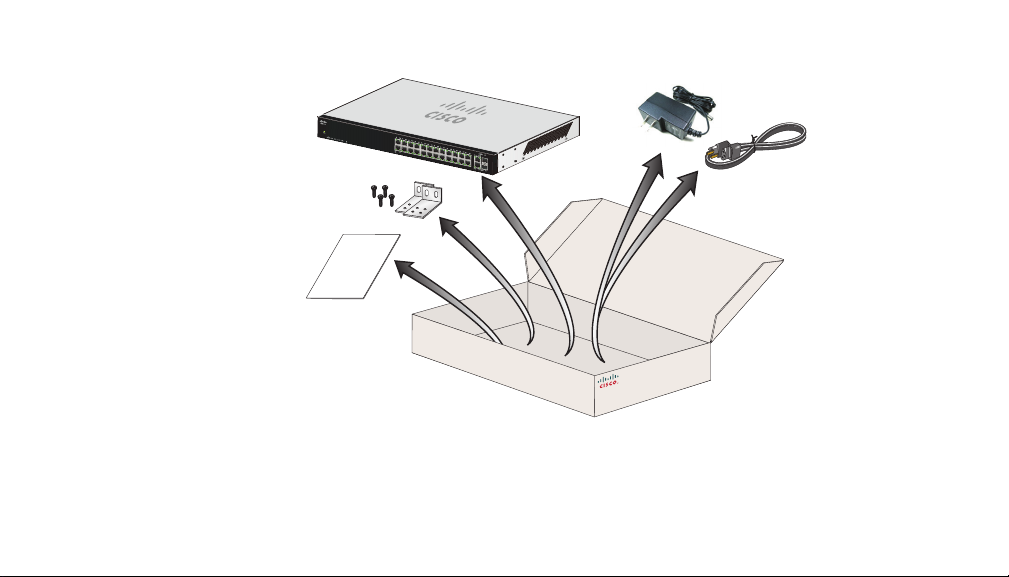
Unbox
239954
2 1 10 Ser i es Un m anage d Swit c hes
Page 3
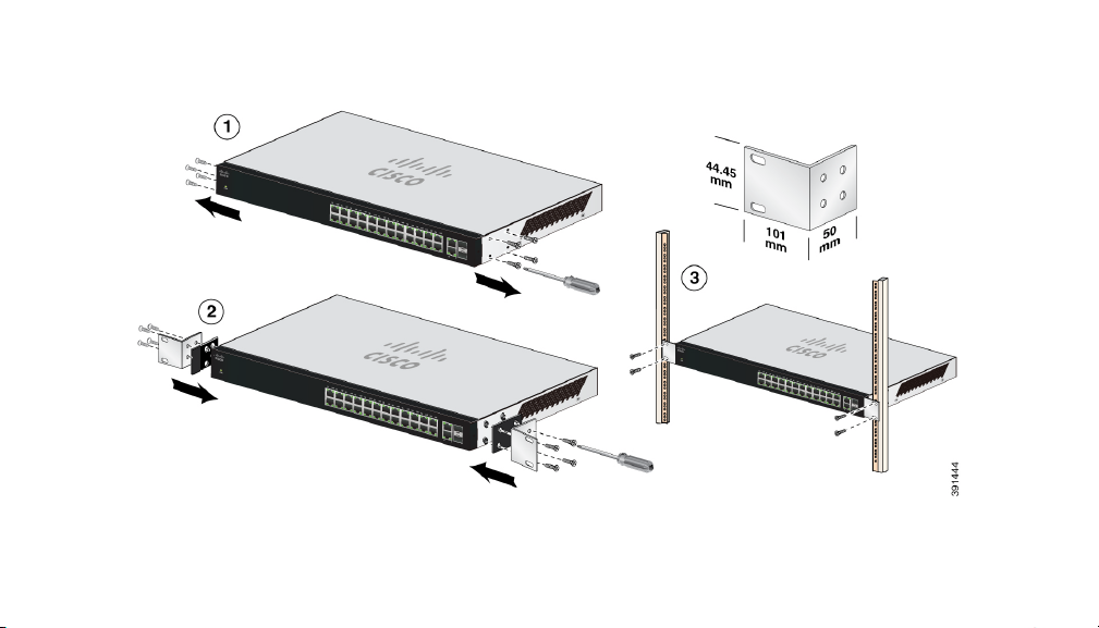
Rack-mount (Optional) - Size 1
110 Series Unmanaged Switches 3
Page 4
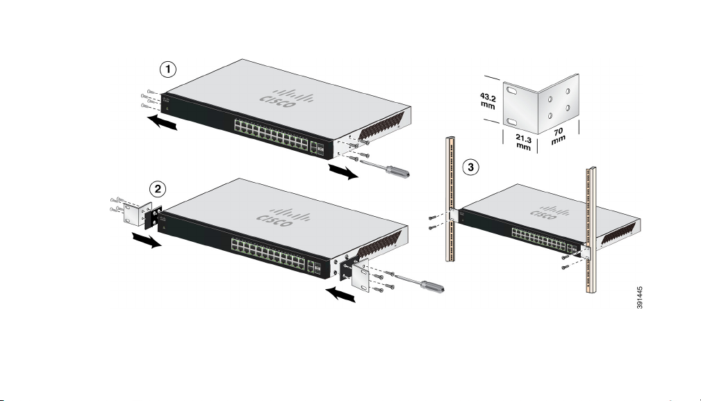
Rack-mount (Optional) - Size 2
4 1 10 Ser i es Un m anage d Swit c hes
Page 5
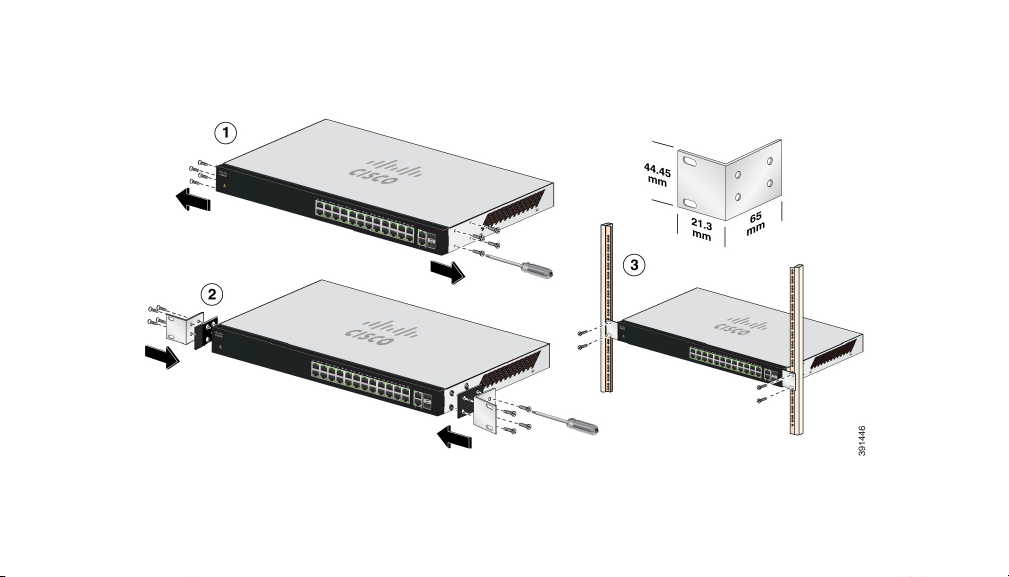
Rack-mounting SG110-24 and SG110-24HP
110 Series Unmanaged Switches 5
Page 6

Rack-mounting SG112-24
6 1 10 Ser i es Un m anage d Swit c hes
Page 7

Safety Instructions for Rack Mounting
Safety Instructions - Rack
Mount
The following or similar rack-mount instructions are included with the installation instructions.
A) Elevated Operating Ambient - If installed in a closed or multi-rack assembly, the operating ambient
temperature of the rack environment may be greater than room ambient. Therefore, consideration
should be given to installing the equipment in an environment compatible with the maximum ambient
temperature (Tma) specified by the manufacturer.
B) Reduced Air Flow - Installation of the equipment in the rack should be such that the amount of air
flow required for safe operation of the equipment is not compromised.
C) Mechanical Loading - Mounting of the equipment in the rack should be such that a hazardous
condition is not achieved due to uneven mechanical loading.
D) Circuit Overloading - Consideration should be given to the connection of the equipment to the
supply circuit and the effect that overloading of the circuits might have on overcurrent protection and
supply wiring. Appropriate consideration of equipment nameplate ratings should be used when
addressing these concerns.
E) Reliable Earthing - Reliable Earthing of rack-mounted equipment should be maintained. Particular
attention should be given to supply connections other than direct connections to the branch current
(e.g. use of power strips).”
110 Series Unmanaged Switches 7
Page 8

Wall-mount (Optional)
X.XX=
SG110D-05, SF110D-05 1.7 in/43 mm
SF110D-08/08HP/16/16HP, SG110D-08/08HP 2.5 in/63 mm
SF110-16/24, SG110-16/16HP 3.7 in/94 mm
8 1 10 Ser i es Un m anage d Swit c hes
Page 9

Wall-mount if needed (continued)
1
2
4
3
SF110D-05/08, SG110D-05, SF110D-16/16HP
1=0.3 in/7.6 mm 2=0.6 in/15 mm 3=0.17 in/4.3 mm 4=0.6 in/15.7 mm
SF110D-08HP, SG110D-08/08HP
1=0.3 in/7.7 mm 2=0.85 in/21.8 mm 3=0.25 in/6.5 mm 4=0.68 in/17.4 mm
SF110-16/24, SG110-16/16HP
1=0.31 in/8 mm 2=0.87 in/22.2 mm 3=0.27 in/6.8 mm 4=0.62 in/17.6 mm
110 Series Unmanaged Switches 9
Page 10

Wall Mount - Placement Options
To install the switch, either set it on its four rubber pads and place it on a flat sur face, or mount it on a wall using the wall-mount slots on the
bottom panel of the switch.
To use the wall mount option, follow these steps:
Step 1 : Attach two screws to the wall such that the wall-mount slots of the switch lineup with the two screws.
SF110D-05 - The screws should be 1.7 in (43 mm) apart.
SF110D-08 - The screws should be 2.5 in (63.5 mm) apart.
SF110D-16 - The screws should be 2.5 in (63.5 mm) apart.
The wall-mount slots are two criss-cross slots on the bottom panel of the switch.
Step 2: Maneuver the switch to insert the screws into the two wall-mount slots.
10 110 S eries Unman aged S witch es
Page 11

Power On Switch
239957
110 Series Unmanaged Switches 11
Page 12

Attach Devices
239958
12 110 S eries Unman aged S witch es
Page 13

Ambient Temperature Ratings
Switch Model Temperature Range
SF110D-05 32o to 122o F (0o to 50o C)
SF110D-08 32o to 122o F (0o to 50o C)
SF110D-08HP 32o to 122o F (0o to 50o C)
SF110-16 32o to 122o F (0o to 50o C)
SF110D-16 32o to 122o F (0o to 50o C)
SF110D-16HP 32o to 122o F (0o to 50o C)
SF110-24 32o to 122o F (0o to 50o C)
SF112-24 32o to 122o F (0o to 50o C)
SG110D-05 32o to 122o F (0o to 50o C)
SG110D-08 32o to 122o F (0o to 50o C)
SG110D-08HP 32o to 122o F (0o to 50o C)
SG110-16 32o to 122o F (0o to 50o C)
SG110-16HP 32o to 122o F (0o to 50o C)
110 Series Unmanaged Switches 13
Page 14

Switch Model Temp e ratu r e Ran g e
SG110-24 32o to 122o F (0o to 50o C)
SG110-24HP 32o to 113o F (0o to 45o C)
SG112-24 32o to 122o F (0o to 50o C)
14 110 S eries Unman aged S witch es
Page 15

110 Series Unmanaged Switches:
www.cisco.com/go/110switches
Regulatory, Compliance, and Safety Information:
www.cisco.com/go/110switches
Click on the Resources tab, and scroll down to Technical Documentation.
End User License Agreement:
www.cisco.com/go/eula
Warranty Information:
www.cisco-warrantyfinder.com
EU lot 26 related test result
www.cisco.com/go/eu-lot26-results
110 Series Unmanaged Switches 15
Page 16

Americas Headquarters
Cisco Systems, Inc.
170 West Tasman Drive
San Jose, CA 95134-1706
USA
www.cisco.com
Support US: 1-866-606-1866
Support, Global: www.cisco.com/go/sbsc
Cisco and the Cisco Logo are trademarks of Cisco Systems, Inc. and/or its affiliates in the U.S. and other countries. A
listing of Cisco's trademarks can be found at www.cisco.com/go/trademarks. Third party trademarks mentioned are
the property of their respective owners. The use of the word partner does not imply a partnership relationship between
Cisco and any other company. (1005R)
© 2014 Cisco Systems, Inc. All rights reserved.
78-100337-01
B0
 Loading...