

Page 1

CHA PTER
DLPs F300 to F399
DLP-F300 Install Fiber-Optic Cables for SNCP Configurations
Purpose This task installs the fiber-optic cables to the SNCP ports at each node. See
Chapter 5, “Turn Up a Network.” to provision and test SNCP
configurations.
Tools/Equipment Fiber-optic cables
Prerequisite Procedures NTP-F119 Install the STM-N Cards, page 2-4
NTP-F231 Clean Fiber Connectors and Adapters, page 14-16
Required/As Needed As needed
Onsite/Remote Onsite
Security Level None
18
Caution To avoid loss of traffic, do not create an SNCP using two ports on the same card. You can create an SNCP
on different ports on the same side of the shelf, but Cisco recommends using one port on one side of the
shelf and another port on the opposite side.
Note See Table 16-1 on page 16-19 and Table 16-2 on page 16-19 for OGI connector pinouts of STM-16 and
STM-64 cards.
Step 1 Plug the fiber into the transmit (Tx) connector of an STM-N card at one node and plug the other end of
the fiber into the receive (Rx) connector of an STM-N card at the adjacent node. The card will display
an SF LED if the transmit and receive fibers are mismatched (one fiber connects a receive port on one
card to a receive port on another card, or the same situation with transmit ports).
Step 2 Repeat Step 1 until you have configured the ring.
Step 3 Return to your originating procedure (NTP).
October 2007
Cisco ONS 15600 SDH Procedure Guide, R8.0
18-1
Page 2

Chapter 18 DLPs F300 to F399
DLP- F301 Edit SNCP Dual-Ring Interconnect Circuit Hold-Off Timer
DLP-F301 Edit SNCP Dual-Ring Interconnect Circuit Hold-Off Timer
Purpose This task changes the amount of time a path selector switch is delayed for
circuits routed on an SNCP dual-ring interconnect (DRI) topology. Setting
a switch hold-off time (HOT) prevents unnecessary back and forth
switching when a circuit is routed through multiple SNCP selectors.
Tools/Equipment None
Prerequisite Procedures NTP-F152 Provision SNCP Nodes, page 5-13
DLP-F181 Log into CTC, page 16-34
Required/As Needed As needed
Onsite/Remote Onsite or remote
Security Level Provisioning or higher
Note Cisco recommends that you set the DRI port HOT value to zero and the circuit path selector HOT value
to a number equal to or greater than zero.
Step 1 From the View menu, choose Go to Network View.
Step 2 Click the Circuits tab.
Step 3 Click the SNCP circuit you want to edit, then click Edit.
Step 4 In the Edit Circuit window, click the SNCP Selectors tab.
Step 5 Create a hold-off time for the circuit source and destination ports:
a. In the Hold-Off Timer area, double-click the cell of the circuit source port (top row), then type the
new hold-off time. The range is 0 to 10,000 ms in increments of 100.
b. In the Hold-Off Timer area, double-click the cell of the circuit destination port (bottom row), then
type the hold-off time entered in Step a.
Step 6 Click Apply, then close the Edit Circuit window by choosing Close from the File menu.
Step 7 Return to your originating procedure (NTP).
DLP-F302 Change Tunnel Type
Purpose This task converts a traditional DCC tunnel to an IP-encapsulated tunnel or
Tools/Equipment None
Prerequisite Procedures DLP-F244 Create a DCC Tunnel, page 17-36
Required/As Needed As needed
Onsite/Remote Onsite or remote
Security Level Provisioning or higher
an IP-encapsulated tunnel to a traditional DCC tunnel.
DLP-F166 Create an IP-Encapsulated Tunnel, page 16-9
18-2
Cisco ONS 15600 SDH Procedure Guide, R8.0
October 2007
Page 3

Chapter 18 DLPs F300 to F399
Step 1 From the View menu, choose Go to Network View.
Step 2 Click the Provisioning > Overhead Circuits tabs.
Step 3 Click the circuit tunnel that you want to convert.
Step 4 Click Edit.
Step 5 In the Edit Circuit window, click the Tunnel tab.
Step 6 In the Attributes area, complete the following:
Step 7 Click Apply.
Step 8 In the confirmation dialog box, click Ye s to continue.
Step 9 In the Circuit Changed status box, click OK to acknowledge that the circuit change was successful.
Step 10 Return to your originating procedure (NTP).
DLP- F303 Delete Overhead Circuits
• If you are converting a traditional DCC tunnel to an IP-encapsulated tunnel, check the Change to
IP Tunnel check box and type the percentage of total DCC bandwidth used in the Maximum
Bandwidth field (the minimum percentage is 10 percent).
• If you are converting an IP tunnel to a traditional DCC tunnel, check the Change to RS-DCC
Tunnel check box.
DLP-F303 Delete Overhead Circuits
Purpose This task deletes overhead circuits. ONS 15600 SDH overhead circuits
include DCC tunnels and IP-encapsulated tunnels.
Tools/Equipment None
Prerequisite Procedures DLP-F181 Log into CTC, page 16-34
Required/As Needed As needed
Onsite/Remote Onsite or remote
Security Level Provisioning or higher
Caution Deleting overhead circuits is service affecting if the circuit ports are in service. To put circuit ports out
of service, see the “DLP-F254 Change the Service State for a Port” task on page 17-47.
Step 1 From the View menu, choose Go to Network View.
Step 2 Click the Provisioning > Overhead Circuits tabs.
Step 3 Click the overhead circuit that you want to delete.
Step 4 Click Delete.
Step 5 In the confirmation dialog box, click Ye s to continue.
Step 6 Return to your originating procedure (NTP).
October 2007
Cisco ONS 15600 SDH Procedure Guide, R8.0
18-3
Page 4

DLP- F304 Repair an IP Tunnel
DLP-F304 Repair an IP Tunnel
Purpose This task repairs circuits that are in the PARTIAL status as a result of node
Tools/Equipment None
Prerequisite Procedures See Chapter 6, “Create Circuits.” for circuit creation procedures.
Required/As Needed As needed
Onsite/Remote Onsite or remote
Security Level Provisioning or higher
Step 1 Obtain the original IP address of the node in question.
Step 2 From the View menu, choose Go to Network View.
Step 3 From the Tools menu, choose Overhead Circuits > Repair IP Circuits.
Step 4 Review the text in the IP Repair wizard and click Next.
Step 5 In the Node IP address area, complete the following:
Chapter 18 DLPs F300 to F399
IP address changes.
• Node—Choose the node that has a PARTIAL circuit.
• Old IP Address—Type the node’s original IP address.
Step 6 Click Next.
Step 7 Click Finish.
Step 8 Return to your originating procedure (NTP).
DLP-F305 Provision Path Trace on Circuit Source and Destination Ports
Purpose This task creates a path trace on VC circuit source ports and destination.
Tools/Equipment ONS 15600 SDH cards capable of transmitting and receiving path trace
must be installed at the circuit source and destination ports. See Table 18-1
for a list of cards.
Prerequisite Procedures DLP-F181 Log into CTC, page 16-34
Required/As Needed As needed
Onsite/Remote Onsite or remote
Security Level Provisioning or higher
18-4
Note This task assumes you are setting up path trace on a bidirectional circuit and setting up transmit strings
at the circuit source and destination.
Step 1 From the View menu, choose Go to Network View.
Step 2 Click the Circuits tab.
Step 3 For the VC circuit you want to monitor, verify that the source and destination ports are on a card that can
transmit and receive the path trace string. Table 18-1 provides a list of cards that support path trace.
Cisco ONS 15600 SDH Procedure Guide, R8.0
October 2007
Page 5

Chapter 18 DLPs F300 to F399
Step 4 Choose the VC circuit you want to trace, then click Edit.
Step 5 In the Edit Circuit window, click the Show Detailed Map check box at the bottom of the window. A
Step 6 Provision the circuit source transmit string:
DLP- F305 Provision Path Trace on Circuit Source and Destination Ports
Table 18-1 ONS 15600 SDH Cards for Path Trace
J1 Function Cards
Transmit and Receive ASAP (Gigabit Ethernet ports)
Receive Only ASAP (Optical ports)
OC48/STM16 LR/LH 16 Port 1550
OC48/STM16 SR/SH 16 Port 1310
OC192/STM64 LR/LH 4 Port 1550
OC192/STM64 SR/SH 4 Port 1310
OC192/STM64 4 Port ITU C-Band
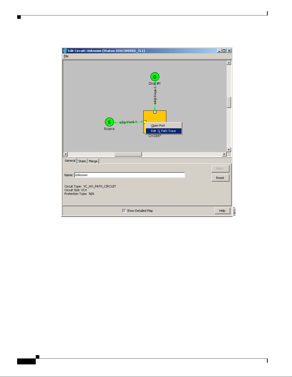
detailed map of the source and destination ports appears.
a. On the detailed circuit map, right-click the circuit source port (the square on the left or right of the
source node icon) and choose Edit J1 Path Trace (port) from the shortcut menu. Figure 18-1 shows
an example.
October 2007
Cisco ONS 15600 SDH Procedure Guide, R8.0
18-5
Page 6
DLP- F305 Provision Path Trace on Circuit Source and Destination Ports
Figure 18-1 Selecting the Edit Path Trace Option
Chapter 18 DLPs F300 to F399
18-6
b. In the New Expected String field, enter the circuit source transmit string. Enter a string that makes
the source port easy to identify, such as the node IP address, node name, circuit name, or another
string. If the New Expected String field is left blank, the J1 transmits a string of null characters.
c. Click Apply, then click Close.
Step 7 Provision the circuit destination transmit string:
a. On the detailed circuit map, right-click the circuit destination port and choose Edit Path Trace from
the shortcut menu (Figure 18-1).
b. In the New Expected String field, enter the string that you want the circuit destination to transmit.
Enter a string that makes the destination port easy to identify, such as the node IP address, node
name, circuit name, or another string. If the New Expected String field is left blank, the J1 transmits
a string of null characters.
c. Click Apply.
Step 8 Provision the circuit destination expected string:
a. On the Circuit Path Trace window, enable the path trace expected string by choosing Auto or
Manual from the Path Trace Mode drop-down list:
Cisco ONS 15600 SDH Procedure Guide, R8.0
October 2007
Page 7

Chapter 18 DLPs F300 to F399
DLP- F305 Provision Path Trace on Circuit Source and Destination Ports
• Auto—The first string received from the source port is automatically provisioned as the current
expected string. An alarm is raised when a string that differs from the baseline is received.
• Manual—The string entered in the Current Expected String field is the baseline. An alarm is
raised when a string that differs from the Current Expected String is received.
b. If you set the Path Trace Mode field to Manual, enter the string that the circuit destination should
receive from the circuit source in the New Expected String field. If you set Path Trace Mode to Auto,
skip this step.
c. Click the Disable AIS and RDI if TIM-P is detected check box if you want to suppress the alarm
indication signal (AIS) and remote defect indication (RDI) when the VC Path Trace Identifier
Mismatch Path (TIM-P) alarm appears. Refer to the Cisco ONS 15600 SDH Troubleshooting Guide
for descriptions of alarms and conditions.
d. (Check box visibility depends on card selection.) Click the Disable AIS on C2 Mis-Match check
box if you want to suppress the AIS when a C2 mismatch occurs.
e. Click Apply, then click Close.
Note It is not necessary to set the format (16 or 64 bytes) for the circuit destination expected
string; the path trace process automatically determines the format.
Step 9 Provision the circuit source expected string:
a. In the Edit Circuit window (with Show Detailed Map chosen; see Figure 18-1 on page 18-6),
right-click the circuit source port and choose Edit Path Trace from the shortcut menu.
b. In the Circuit Path Trace window, enable the path trace expected string by choosing Auto or Manual
from the Path Trace Mode drop-down list:
• Auto—Uses the first string received from the port at the other path trace end as the baseline
string. An alarm is raised when a string that differs from the baseline is received.
• Manual—Uses the Current Expected String field as the baseline string. An alarm is raised when
a string that differs from the Current Expected String is received.
c. If you set the Path Trace Mode field to Manual, enter the string that the circuit source should receive
from the circuit destination in the New Expected String field. If you set Path Trace Mode to Auto,
skip this step.
d. Click the Disable AIS and RDI if TIM-P is detected check box if you want to suppress the AIS
and RDI when the TIM-P alarm appears. Refer to the Cisco ONS 15600 SDH Troubleshooting Guide
for descriptions of alarms and conditions.
e. (Check box visibility depends on card selection.) Click the Disable AIS on C2 Mis-Match check
box if you want to suppress the AIS when a C2 mismatch occurs.
f. Click Apply.
Note It is not necessary to set the format (16 or 64 bytes) for the circuit source expected string;
the path trace process automatically determines the format.
October 2007
Step 10 After you set up the path trace, the received string appears in the Received field on the path trace setup
window. The following options are available:
• Click Hex Mode to display path trace in hexadecimal format. The button name changes to
ASCII Mode. Click it to return the path trace to ASCII format.
• Click the Reset button to reread values from the port.
Cisco ONS 15600 SDH Procedure Guide, R8.0
18-7
Page 8

DLP- F306 Provision Path Trace on STM-N Ports
• Click Default to return to the path trace default settings (Path Trace Mode is set to Off and the
New Transmit and New Expected Strings are null).
Caution Clicking Default will generate alarms if the port on the other end is provisioned with a different string.
The expect and receive strings are updated every few seconds if the Path Trace Mode field is set to Auto
or Manual.
Step 11 Click Close.
The detailed circuit window indicates path trace with an M (manual path trace) or an A (automatic path
trace) at the circuit source and destination ports.
Step 12 Return to your originating procedure (NTP).
DLP-F306 Provision Path Trace on STM-N Ports
Chapter 18 DLPs F300 to F399
Purpose This task monitors a path trace on STM-N ports within the circuit path.
Tools/Equipment The STM-N ports you want to monitor must be on STM-N cards capable
of receiving path trace. See Table 18-1 on page 18-5.
Prerequisite Procedures DLP-F305 Provision Path Trace on Circuit Source and Destination Ports,
page 18-4
DLP-F181 Log into CTC, page 16-34
Required/As Needed As needed
Onsite/Remote Onsite or remote
Security Level Provisioning or higher
Step 1 From the View menu, choose Go to Other Node. In the Select Node dialog box, choose the node where
path trace was provisioned on the circuit source and destination ports.
Step 2 Click Circuits.
Step 3 Choose the VC circuit that has path trace provisioned on the source and destination ports, then click
Edit.
Step 4 In the Edit Circuit window, click the Show Detailed Map check box at the bottom of the window. A
detailed circuit graphic showing source and destination ports appears.
Step 5 In the detailed circuit map right-click the circuit STM-N port (the square on the left or right of the source
node icon) and choose Edit Path Trace from the shortcut menu.
18-8
Note The STM-N port must be on a receive-only card listed in Table 18-1 on page 18-5. If not, the
Edit Path Trace menu item will not appear.
Step 6 In the Circuit Path Trace window, enable the path trace expected string by choosing Auto or Manual
from the Path Trace Mode drop-down list:
Cisco ONS 15600 SDH Procedure Guide, R8.0
October 2007
Page 9

Chapter 18 DLPs F300 to F399
• Auto—Uses the first string received from the port at the other path trace end as the current expected
string. An alarm is raised when a string that differs from the baseline is received. For STM-N ports,
Auto is recommended because Manual mode requires you to trace the circuit on the Edit Circuit
window to determine whether the port is the source or destination path.
• Manual—Uses the Current Expected String field as the baseline string. An alarm is raised when a
string that differs from the Current Expected String is received.
Step 7 If you set the Path Trace Mode field to Manual, enter the string that the STM-N port should receive in
the New Expected String field. To do this, trace the circuit path on the detailed circuit window to
determine whether the port is in the circuit source or destination path, then set the New Expected String
to the string transmitted by the circuit source or destination. If you set the Path Trace Mode field to Auto,
skip this step.
Step 8 Click Apply, then click Close.
Step 9 Return to your originating procedure (NTP).
DLP-F307 Create Login Node Groups
DLP- F307 Create Login Node Groups
Purpose This task creates a login node group to display ONS 15600 SDH nodes that
have an IP connection but not a DCC connection to the login node.
Tools/Equipment None
Prerequisite Procedures DLP-F181 Log into CTC, page 16-34
NTP-F129 Log into the ONS 15600 SDH GUI, page 3-5
Required/As Needed As needed
Onsite/Remote Onsite or remote
Security Level Provisioning or higher
Step 1 From the Edit menu in node view, choose Preferences.
Step 2 Click the Login Node Group tab.
Step 3 Click Create Group.
Step 4 In the Create Login Group Name dialog box, enter a name for the group.
Step 5 Click OK.
Step 6 In the Members area, type the IP address (or node name) of a node you want to add to the group. Click
Add. Repeat this step for each node that you want to add to the group.
Step 7 Click OK.
The next time you log into an ONS 15600 SDH, the login node group will be available in the Additional
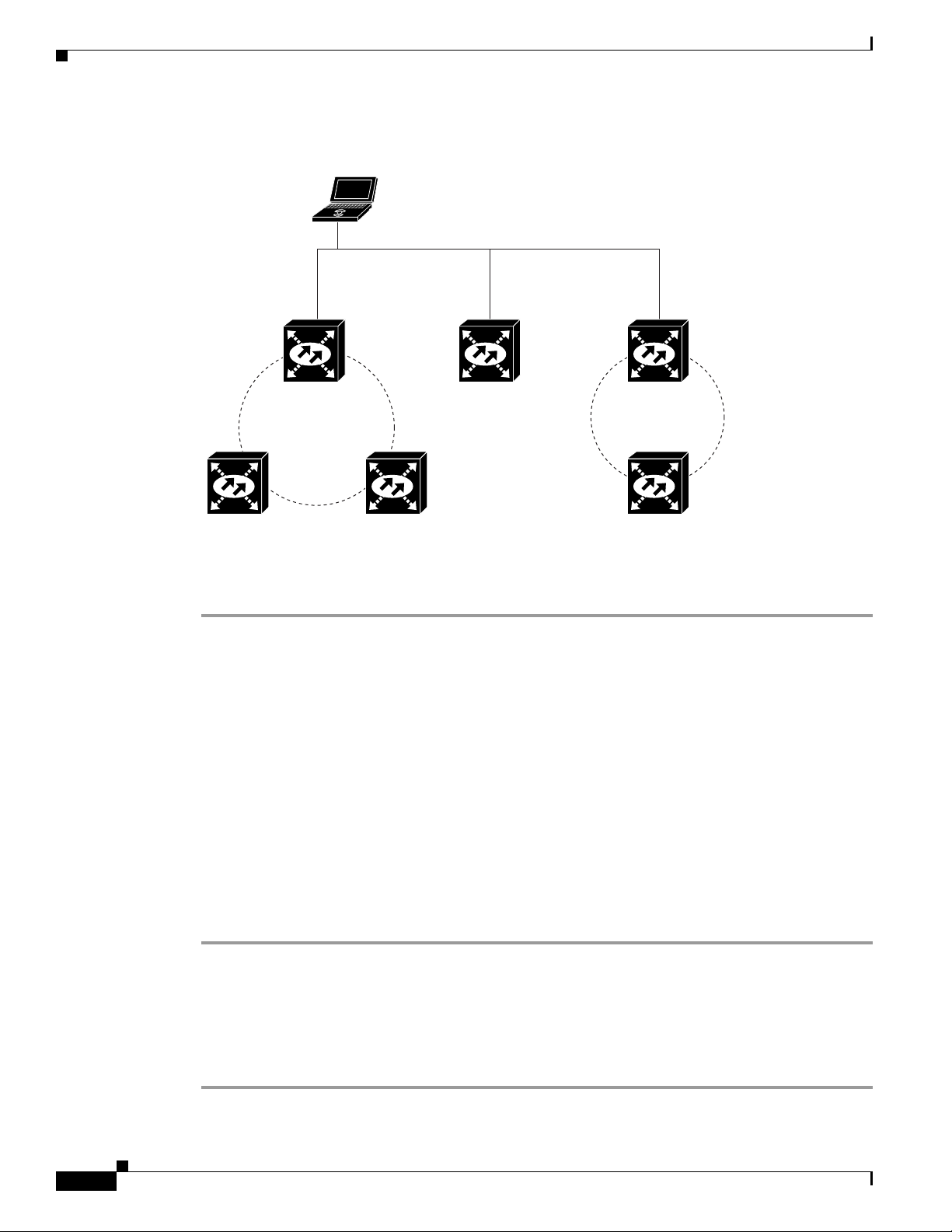
Nodes list of the Login dialog box. For example, in Figure 18-2, a login node group is created that
contains the IP addresses for Nodes 1, 4, and 5. During login, if you choose this group from the
Additional Nodes list and Disable Network Discovery is not selected, all nodes in the figure appear. If
the login group and Disable Network Discovery are both selected, Nodes 1, 4, and 5 appear. You can
create as many login groups as you need. The groups are stored in the CTC preferences file and are not
visible to other users.
October 2007
Cisco ONS 15600 SDH Procedure Guide, R8.0
18-9
Page 10
DLP- F308 Delete a Node from the Current Session or Login Group
Figure 18-2 Login Node Group
Laptop PC
IP Address
192.168.106.100
Chapter 18 DLPs F300 to F399
LAN/WAN (Ethernet)
Step 8
Node 1
IP Address
192.168.106.143
Three node ring
192.168.105.119
Node 3Node 2
Return to your originating procedure (NTP).
Node 4
IP Address
Single
Node 5
IP Address
192.168.104.109
Two node ring
Node 6
IP Address
192.168.103.199
DLP-F308 Delete a Node from the Current Session or Login Group
83116
18-10
Purpose This task removes a node from the current CTC session or login node
group. To remove a node from a login node group that is not the current
one, see “DLP-F312 Delete a Node from a Specified Login Node Group”
task on page 18-13.
Tools None
Prerequisite Procedures DLP-F181 Log into CTC, page 16-34
Required/As Needed As needed
Onsite/Remote Onsite or remote
Security Level Provisioning or higher
Step 1 From the View menu, choose Go to Network View.
Step 2 Click the node that you want to delete.
Step 3 From the File menu, click Delete Selected Node.
After a few seconds, the node disappears from the network view map.
Step 4 Return to your originating procedure (NTP).
Cisco ONS 15600 SDH Procedure Guide, R8.0
October 2007
Page 11

Chapter 18 DLPs F300 to F399
DLP- F309 Configure the CTC Alerts Dialog Box for Automatic Popup
DLP-F309 Configure the CTC Alerts Dialog Box for Automatic Popup
Purpose This task sets up the CTC Alerts dialog box to open for all alerts, for circuit
deletion errors only, or never. The CTC Alerts dialog box displays
information about network disconnection, Send-PDIP inconsistency,
circuit deletion status, condition retrieval errors, and software download
failure.
Tools None
Prerequisite Procedures DLP-F181 Log into CTC, page 16-34
Required/As Needed As needed
Onsite/Remote Onsite or remote
Security Level Provisioning or higher
Step 1 Click the CTC Alerts toolbar icon.
Step 2 In the CTC Alerts dialog box, choose one of the following:
• All alerts—Sets the CTC Alerts dialog box to open automatically for all notifications.
• Error alerts only—Sets the CTC Alerts dialog box to open automatically for circuit deletion errors
only.
• Never—Sets the CTC Alerts dialog box to never open automatically.
Step 3 Click Close.
Step 4 Return to your originating procedure (NTP).
DLP-F310 Change the JRE Version
Purpose This task changes the Java Runtime Environment (JRE) version, which is
useful if you would like to upgrade to a later JRE version from an earlier
one without using the software CD. This does not affect the browser default
version. After selecting the desired JRE version, you must exit CTC. The
next time you log into a node, the new JRE version will be used.
Tools None
Prerequisite Procedures DLP-F181 Log into CTC, page 16-34
Required/As Needed As needed
Onsite/Remote Onsite or remote
Security Level Provisioning or higher
Note JRE 5.0 is required to run Software R8.0.
October 2007
Step 1 From the Edit menu, choose Preferences.
Step 2 Click the JRE tab. The JRE tab shows the current JRE version and the recommended version.
Step 3 Click the Browse button and navigate to the JRE directory on your computer.
Cisco ONS 15600 SDH Procedure Guide, R8.0
18-11
Page 12

DLP- F311 Remove Pass-through Connections
Step 4 Choose the JRE version.
Step 5 Click OK.
Step 6 From the File menu, choose Exit.
Step 7 In the confirmation dialog box, click Ye s.
Step 8 Return to your originating procedure (NTP).
DLP-F311 Remove Pass-through Connections
Purpose This task removes pass-through connections from a node deleted from a
ring.
Tools/Equipment None
Prerequisite Procedures DLP-F181 Log into CTC, page 16-34
Required/As Needed As needed
Onsite/Remote Onsite or remote
Security Level Provisioning or higher
Chapter 18 DLPs F300 to F399
Step 1 Log into the deleted node.
Step 2 In the CTC Login dialog box, check the Disable Network Discovery check box.
Step 3 Choose None from the Additional Nodes drop-down list.
Step 4 Click the Login button.
Step 5 Click the Circuits tab. All internode circuits are shown as PARTIAL.
Step 6 Refer to the diagram or CTC printout you created in the “NTP-F215 Remove an MS-SPRing Node”
procedure on page 13-5 or the “NTP-F217 Remove an SNCP Node” procedure on page 13-10. Find the
circuits on the line cards of the removed node.
Step 7 Click the Filter button.
Step 8 Type the slot and port of a trunk card on the removed node.
Step 9 Click OK.
Step 10 In the Circuits tab, select all PARTIAL circuits that pass the filter and click the Delete button.
Note To select more than one circuit, press the Shift key and simultaneously click on all circuits to be
deleted.
Step 11 Repeat Steps 6 through 10 for the other trunk card.
Step 12 Log out of CTC.
Step 13 Return to your originating procedure (NTP).
18-12
Cisco ONS 15600 SDH Procedure Guide, R8.0
October 2007
Page 13

Chapter 18 DLPs F300 to F399
DLP- F312 Delete a Node from a Specified Login Node Group
DLP-F312 Delete a Node from a Specified Login Node Group
Purpose This task removes a node from a login node group.
Tools None
Prerequisite Procedures DLP-F181 Log into CTC, page 16-34
Required/As Needed As needed
Onsite/Remote Onsite or remote
Security Level Provisioning or higher
Step 1 From the CTC Edit menu, choose Preferences.
Step 2 In the Preferences dialog box, click the Login Node Groups tab.
Step 3 Click the login node group tab containing the node you want to remove.
Step 4 Click the node you want to remove, then click Remove.
Step 5 Click OK.
Step 6 Return to your originating procedure (NTP).
DLP-F313 Change a Circuit Service State
Purpose This task changes the service state of a circuit.
Tools/Equipment None
Prerequisite Procedures DLP-F181 Log into CTC, page 16-34
Required/As Needed As needed
Onsite/Remote Onsite or remote
Security Level Provisioning or higher
Step 1 From the View menu, choose Go to Network View.
Step 2 Click the Circuits tab.
Step 3 Click the circuit with the state that you want to change.
Step 4 From the Tools menu, choose Circuits > Set Circuit State.
Step 5 In the Set Circuit State dialog box, choose the administrative state from the Target Circuit Admin State
drop-down list:
• Unlocked—Puts the circuit cross-connects in the Unlocked-enabled service state.
• Locked,disabled—Puts the circuit cross-connects in the Locked-enabled,disabled service state.
Traffic is not passed on the circuit.
• Unlocked,automaticInService—Puts the circuit cross-connects in the
Unlocked-disabled,automaticInService service state and suppresses alarms and conditions. When
the connections receive a valid signal, the service state automatically changes to Unlocked-enabled.
October 2007
Cisco ONS 15600 SDH Procedure Guide, R8.0
18-13
Page 14

DLP- F314 Provision MS-DCC Terminations
• Locked,maintenance—Puts the circuit cross-connects in the Locked-enabled,maintenance service
state. The maintenance state does not interrupt traffic flow; it suppresses alarms and conditions and
allows loopbacks to be performed on the circuit. Use Locked,maintenance for circuit testing or to
suppress circuit alarms temporarily. Change the administrative state to Unlocked;
Unlocked,automaticInService; or Locked,disabled when testing is complete.
Note Alternatively, you can choose the circuit on the Circuits tab, click the Edit button, then click the
State tab on the Edit Circuits window.
For additional information about circuit service states, refer to the “Circuits and Tunnels” chapter in the
Cisco ONS 15600 SDH Reference Manual.
Step 6 If you want to apply the state to the circuit source and destination ports, check the Apply to Drop Ports
check box.
Note CTC will not allow you to change a drop port service state from Unlocked-enabled to
Locked-enabled,disabled. You must first change a port to the Locked-enabled,maintenance
service state before putting it in the Locked-enabled,disabled service state.
Chapter 18 DLPs F300 to F399
Step 7 Click Apply.
Step 8 If the Apply to Ports Results dialog box appears, view the results and click OK.
CTC will not change the service state of the circuit source and destination port in certain circumstances.
For example, if a port is in loopback (Locked-enabled,loopback & maintenance), CTC will not change
the port to Unlocked-enabled. In another example, if the circuit size is smaller than the port, CTC will
not change the port service state from Unlocked-enabled to Locked-enabled,disabled. If CTC cannot
change the port service state, you must change the port service state manually. For more information,
see the “DLP-F254 Change the Service State for a Port” task on page 17-47.
Step 9 Return to your originating procedure (NTP).
DLP-F314 Provision MS-DCC Terminations
Purpose This task creates the MS-DCC terminations required for alarms,
administration, data, signal control information, and messages. In this task,
you can also set up the node so that it has direct IP access to a far-end
non-ONS node over the DCC network.
Tools/Equipment None
Prerequisite Procedures DLP-F181 Log into CTC, page 16-34
Required/As Needed As needed
Onsite/Remote Onsite or remote
Security Level Provisioning or higher
18-14
Cisco ONS 15600 SDH Procedure Guide, R8.0
October 2007
Page 15

Chapter 18 DLPs F300 to F399
Step 1 In node view, click the Provisioning > Comm Channels > MS-DCC tabs.
Step 2 Click Create.
Step 3 In the Create MS-DCC Terminations dialog box, click the ports where you want to create the MS-DCC
DLP- F314 Provision MS-DCC Terminations
Note When MS-DCC is provisioned, an RS-DCC termination is allowed on the same port, but is not
recommended. RS-DCC and MS-DCC are only needed on the same port during a software
upgrade if the software version does not support MS-DCC. Changing configuration of a port
having MS-DCC termination to RS-DCC termination is allowed. During this procedure both
MS-DCC and RS-DCC terminations can be present on the same port. Once the RS-DCC
termination is configured see “DLP-F253 Provision RS-DCC Terminations” task on page 17-45
delete the MS-DCC terminations as specified in“DLP-F322 Delete an MS-DCC Termination”
task on page 18-20, and enable the OSPF on RS-DCC termination if not enabled see “DLP-F319
Change an RS-DCC Termination” task on page 18-19.
termination. To select more than one port, press the Shift key or the Ctrl key.
Note MS-DCC refers to the multiplex section DCC, which is used for ONS 15600 SDH DCC
terminations. The SDH MS-DCCs and the RS-DCC (when not used as a DCC termination by the
ONS 15600 SDH) can be provisioned as DCC tunnels. See the “DLP-F244 Create a DCC
Tunnel” task on page 17-36.
Step 4 In the Port Admin State area, click Set to unlocked to put the port in service.
Step 5 Verify that the Disable OSPF on DCC Link check box is unchecked.
Step 6 If the RS-DCC termination is to include a non-ONS node, check the Far End is Foreign check box. This
automatically sets the far-end node IP address to 0.0.0.0, which means that any address can be specified
by the far end. To change the default to a specific the IP address, see the “DLP-F320 Change an MS-DCC
Termination” task on page 18-19.
Step 7 In the Layer 3 area, perform one of the following:
• Check the IP box only—If the MS-DCC is between the ONS 15600 SDH and another ONS node and
only ONS nodes reside on the network. The MS-DCC will use point-to-point protocol (PPP).
• Check the IP and OSI boxes—If the MS-DCC is between the ONS 15600 SDH and another ONS
node and third party NEs that use the OSI protocol stack are on the same network. The MS-DCC
will use PPP.
Note Checking only the OSI box (LAP-D) is not available for MS-DCCs.
Step 8 If you checked OSI, complete the following steps. If you checked IP only, continue with Step 9.
a. Click Next.
b. Provision the following fields:
–
Router—Sets the OSI router.
–
ESH—Sets the End System Hello propagation frequency. End system NEs transmit ESHs to
inform other ESs and ISs about the NSAPs it serves. The default is 10 seconds. The range is 10
to 1000 seconds.
October 2007
Cisco ONS 15600 SDH Procedure Guide, R8.0
18-15
Page 16

DLP- F315 Provision a Proxy Tunnel
–
–
–
Step 9 Click Finish.
Note MS-DCC Termination Failure (EOC-L) and Loss of Signal (LOS) alarms appear until you create
Step 10 Return to your originating procedure (NTP).
Chapter 18 DLPs F300 to F399
ISH—Sets the Intermediate System Hello PDU propagation frequency. Intermediate system
NEs send ISHs to other ESs and ISs to inform them about the IS NETs it serves. The default is
10 seconds. The range is 10 to 1000 seconds.
IIH—Sets the Intermediate System to Intermediate System Hello PDU propagation frequency.
The IS-IS Hello PDUs establish and maintain adjacencies between ISs. The default is 3 seconds.
The range is 1 to 600 seconds.
IS-IS Cost—Sets the cost for sending packets on the LAN subnet. The IS-IS protocol uses the
cost to calculate the shortest routing path. The default metric cost for LAN subnets is 20. It
normally should not be changed.
all network DCC terminations and put the DCC termination STM-N ports in service.
DLP-F315 Provision a Proxy Tunnel
Purpose This task sets up a proxy tunnel to communicate with a non-ONS far-end
node. Proxy tunnels are only necessary when the proxy server is enabled
and a foreign DCC termination exists, or if static routes exist so that the
DCC network is used to access remote networks or devices. You can
provision a maximum of 12 proxy server tunnels.
Tools/Equipment None
Prerequisite Procedures DLP-F181 Log into CTC, page 16-34
DLP-F253 Provision RS-DCC Terminations, page 17-45
Required/As Needed As needed
Onsite/Remote Onsite or remote
Security Level Superuser only
Note If the proxy server is disabled, you cannot set up a proxy tunnel.
Step 1 Click the Provisioning > Network > Proxy subtabs.
Step 2 Click Create.
Step 3 In the Create Tunnel dialog box, complete the following:
18-16
• Source Address—Type the IP address of the source node (32 bit length) or source subnet (any other
length).
• Length—Choose the length of the source subnet mask.
• Destination Address—Type the IP address of the destination node (32 bit length) or destination
subnet (any other length).
• Length—Choose the length of the destination subnet mask.
Cisco ONS 15600 SDH Procedure Guide, R8.0
October 2007
Page 17

Chapter 18 DLPs F300 to F399
Step 4 Click OK.
Step 5 Continue with your originating procedure (NTP).
DLP-F316 Provision a Firewall Tunnel
Purpose This task provisions destinations that will not be blocked by the firewall.
Firewall tunnels are only necessary when the proxy server is enabled and a
foreign DCC termination exists, or if static routes exist so that the DCC
network is used to access remote networks or devices. You can provision a
maximum of 12 firewall tunnels.
Tools/Equipment None
Prerequisite Procedures DLP-F181 Log into CTC, page 16-34
DLP-F253 Provision RS-DCC Terminations, page 17-45
Required/As Needed As needed
Onsite/Remote Onsite or remote
Security Level Superuser only
DLP- F316 Provision a Firewall Tunnel
Note If the proxy server is configured as proxy-only or is disabled, you cannot set up a firewall tunnel.
Step 1 Click the Provisioning > Network > Firewall subtabs.
Step 2 Click Create.
Step 3 In the Create Tunnel dialog box, complete the following:
• Source Address—Type the IP address of the source node (32 bit length) or source subnet (any other
length).
• Length—Choose the length of the source subnet mask.
• Destination Address—Type the IP address of the destination node (32 bit length) or destination
subnet (any other length).
• Length—Choose the length of the destination subnet mask.
Step 4 Click OK.
Step 5 Continue with your originating procedure (NTP).
October 2007
Cisco ONS 15600 SDH Procedure Guide, R8.0
18-17
Page 18

DLP- F317 Delete a Proxy Tunnel
DLP-F317 Delete a Proxy Tunnel
Purpose This task removes a proxy tunnel.
Tools/Equipment None
Prerequisite Procedures DLP-F181 Log into CTC, page 16-34
Required/As Needed As needed
Onsite/Remote Onsite or remote
Security Level Superuser only
Step 1 Click the Provisioning > Network > Proxy subtabs.
Step 2 Click the proxy tunnel that you want to delete.
Step 3 Click Delete.
Step 4 Return to your originating procedure (NTP).
Chapter 18 DLPs F300 to F399
DLP-F318 Delete a Firewall Tunnel
Purpose This task removes a firewall tunnel.
Tools/Equipment None
Prerequisite Procedures DLP-F181 Log into CTC, page 16-34
Required/As Needed As needed
Onsite/Remote Onsite or remote
Security Level Superuser only
Step 1 Click the Provisioning > Network > Firewall subtabs.
Step 2 Click the firewall tunnel that you want to delete.
Step 3 Click Delete.
Step 4 Return to your originating procedure (NTP).
18-18
Cisco ONS 15600 SDH Procedure Guide, R8.0
October 2007
Page 19

Chapter 18 DLPs F300 to F399
DLP-F319 Change an RS-DCC Termination
Purpose This task modifies an RS-DCC termination. You can enable or disable Open
Shortest Path First (OSPF) and enable or disable the foreign node setting.
Tools/Equipment None
Prerequisite Procedures DLP-F181 Log into CTC, page 16-34
Required/As Needed As needed
Onsite/Remote Onsite or remote
Security Level Provisioning or higher
Step 1 Click the Provisioning > Comm Channels > RS-DCC tabs.
Step 2 Click the RS-DCC that you want to change.
Step 3 Click Edit.
Step 4 In the RS-DCC Termination Editor dialog box, complete the following as necessary:
• Disable OSPF on RS-DCC Link—If checked, OSPF is disabled on the link. OSPF should be
disabled only when the slot and port connect to third-party equipment that does not support OSPF.
DLP- F319 Change an RS-DCC Termination
• Far End is Foreign—Check this box to specify that the RS-DCC termination is a non-ONS node.
• Far End IP—If you checked the Far End is Foreign check box, type the IP address of the far-end
node or leave the 0.0.0.0 default. An IP address of 0.0.0.0 means that any address can be used by the
far end.
Step 5 Click OK.
Step 6 Return to your originating procedure (NTP).
DLP-F320 Change an MS-DCC Termination
Purpose This task modifies an SDH MS-DCC termination. You can enable or
disable OSPF and enable or disable the foreign node setting.
Tools/Equipment None
Prerequisite Procedures DLP-F181 Log into CTC, page 16-34
Required/As Needed As needed
Onsite/Remote Onsite or remote
Security Level Provisioning or higher
Step 1 Click the Provisioning > Comm Channels > MS-DCC tabs.
Step 2 Click the MS-DCC that you want to change.
October 2007
Step 3 Click Edit.
Step 4 In the MS-DCC Termination Editor dialog box, complete the following as necessary:
• Disable OSPF on MS-DCC Link—If checked, OSPF is disabled on the link. OSPF should be
disabled only when the slot and port connect to third-party equipment that does not support OSPF.
Cisco ONS 15600 SDH Procedure Guide, R8.0
18-19
Page 20

DLP- F321 Delete an RS-DCC Termination
• Far End is Foreign—Check this box to specify that the MS-DCC termination is a non-ONS node.
• Far end IP—If you checked the Far End is Foreign check box, type the IP address of the far-end node
or leave the 0.0.0.0 default. An IP address of 0.0.0.0 means that any address can be used by the far
end.
Step 5 Click OK.
Step 6 Return to your originating procedure (NTP).
DLP-F321 Delete an RS-DCC Termination
Purpose This task deletes an RS-DCC termination.
Tools/Equipment None
Prerequisite Procedures DLP-F181 Log into CTC, page 16-34
Required/As Needed As needed
Onsite/Remote Onsite or remote
Security Level Provisioning or higher
Chapter 18 DLPs F300 to F399
Note Deleting an RS-DCC termination might cause you to lose visibility of nodes that do not have other data
communications channels (DCCs) or network connections to the CTC computer.
Note If you have circuits traversing the fiber on which you delete a DCC termination, the circuits will go to
an Incomplete state.
Step 1 In node view, click the Provisioning > Comm Channel > RS-DCC tabs.
Step 2 Click the RS-DCC termination to be deleted and click Delete. The Delete RS-DCC Termination dialog
box appears.
Step 3 Click Yes in the confirmation dialog box. Confirm that the changes appear; if not, repeat the task.
Step 4 Return to your originating procedure (NTP).
DLP-F322 Delete an MS-DCC Termination
Purpose This task deletes an SDH MS-DCC termination.
Tools/Equipment None
Prerequisite Procedures DLP-F181 Log into CTC, page 16-34
Required/As Needed As needed
Onsite/Remote Onsite or remote
Security Level Provisioning or higher
18-20
Cisco ONS 15600 SDH Procedure Guide, R8.0
October 2007
Page 21

Chapter 18 DLPs F300 to F399
DLP- F323 Use the Reinitialization Tool to Clear the Database and Upload Software (UNIX)
Caution Deleting a DCC termination can cause you to lose visibility of nodes that do not have other DCCs or
network connections to the CTC computer.
Step 1 Click the Provisioning > Comm Channel > MS-DCC tabs.
Step 2 Click the MS-DCC termination to be deleted and click Delete. The Delete MS-DCC Termination dialog
box appears.
Step 3 Click Ye s in the confirmation dialog box. Confirm that the changes appear; if not, repeat the task.
Step 4 Return to your originating procedure (NTP).
DLP-F323 Use the Reinitialization Tool to Clear the Database and Upload
Software (UNIX)
Purpose This task reinitializes the ONS 15600 SDH using the CTC reinitialization
(reinit) tool on a UNIX computer. Reinitialization uploads a new software
package to the TSC cards, clears the node database, and restores the factory
default parameters.
Tools/Equipment Cisco ONS 15600 SDH System Software CD, Version 8.0
JRE 5.0 must be installed on the computer to log into the node at the
completion of the reinitialization. The reinitialization tool can run on
JRE 1.3.1_02, JRE 1.4.2, or JRE 5.0.
Prerequisite procedures DLP-F181 Log into CTC, page 16-34
Required/As needed As needed
Onsite/Remote Onsite or remote
Security Level Superuser only
Note Restoring a node to the factory configuration deletes all cross-connects on the node.
Step 1 Insert the Cisco ONS 15600 SDH System Software CD, Version 8.0, into the computer CD-ROM drive.
If the CTC Installation Wizard appears, click Cancel.
Step 2 To find the recovery tool file, go to the CISCO15600 SDH directory on the CD (usually
/cdrom/cdrom0/CISCO15600SDH).
Step 3 If you are using a file explorer, double-click the RE-INIT.jar file. If you are working with a command
line interface, run java -jar RE-INIT.jar. The NE Reinitialization window appears.
October 2007
Step 4 Complete the following fields:
• GNE IP—If the node you are reinitializing is accessed through another node configured as a gateway
network element (GNE), enter the GNE IP address. If you have a direct connection to the node, leave
this field blank.
• Node IP—Enter the node name or IP address of the node that you are reinitializing.
• User ID—Enter the user ID needed to access the node.
Cisco ONS 15600 SDH Procedure Guide, R8.0
18-21
Page 22

DLP- F324 Provision ASAP Ethernet Ports
• Password—Enter the password for the user ID.
• Upload Package—Check this box to send the software package file to the node. If unchecked, the
software stored on the node is not modified.
• Force Upload—Check this box to send the software package file to the node even if the node is
running the same software version. If unchecked, reinitialization will not send the software package
if the node is already running the same version.
• Activate/Revert—Check this box to activate the uploaded software (if the software is a later than the
installed version) or revert to the uploaded software (if the software is earlier than the installed
version) as soon as the software file is uploaded. If unchecked, the software is not activated or
reverted after the upload, allowing you to initiate the functions later from the node view
Maintenance > Software tabs.
• Re-init Database—Check this box to send a new database to the node. (This is equivalent to the CTC
database restore operation.) If unchecked, the node database is not modified.
• Confirm—Check this box if you want a warning message displayed before any operation is
performed. If unchecked, reinitialization does not display a warning message.
• Search Path—Enter the path to the CISCO15600SDH folder on the CD drive.
Step 5 Click Go.
Chapter 18 DLPs F300 to F399
Caution Before continuing with the next step, verify that the database to upload is correct. You cannot reverse
the upload process after you click Yes.
Step 6 Review the information on the Confirm NE Re-Initialization dialog box, then click Yes to start the
reinitialization.
The reinitialization begins. After the software is downloaded and activated, and the database is uploaded
to the TSC cards, “Complete” appears in the status bar and the TSC cards will reboot. Wait a few minutes
for the reboot to complete.
Step 7 After the reboot is complete, log into the node using the “DLP-F181 Log into CTC” task on page 16-34.
Step 8 Complete the “NTP-F133 Set Up Date, Time, and Contact Information” procedure on page 4-4.
Step 9 Return to your originating procedure (NTP).
DLP-F324 Provision ASAP Ethernet Ports
Purpose This task provisions ASAP Ethernet ports to carry traffic.
Tools/Equipment None
Prerequisite Procedures DLP-F181 Log into CTC, page 16-34
Required/As Needed As needed
Onsite/Remote Onsite or remote
Security Level Provisioning or higher
18-22
Step 1 In the node view, double-click the ASAP card graphic to open the card.
Step 2 Click the Provisioning > Ethernet > Ports tabs.
Cisco ONS 15600 SDH Procedure Guide, R8.0
October 2007
Page 23

Chapter 18 DLPs F300 to F399
Step 3 For each port, provision the following parameters:
Step 4 Click Apply.
Step 5 Refresh the Ethernet statistics:
Step 6 Return to your originating procedure (NTP).
DLP- F325 Provision ASAP POS Ports
• Port Name—If you want to label the port, type the port name.
• Admin State—Choose Unlocked to put the port in service.
• Enable Flow Control—Check this check box to enable flow control on the port (default). If you do
not want to enable flow control, uncheck the box. The ASAP attempts to negotiate symmetrical flow
control with the attached device.
a. Click the Performance > Ethernet > Ether Ports > Statistics tabs.
b. Click Refresh.
Note Reprovisioning an Ethernet port on the ASAP card does not reset the Ethernet statistics for that
port.
DLP-F325 Provision ASAP POS Ports
Purpose This task provisions ASAP packet-over-SDH (POS) ports to carry traffic.
Tools/Equipment None
Prerequisite Procedures DLP-F181 Log into CTC, page 16-34
Required/As Needed As needed
Onsite/Remote Onsite or remote
Security Level Provisioning or higher
Step 1 In the node view, double-click the ASAP card graphic to open the card.
Step 2 Click the Provisioning > Ethernet > POS Ports tabs.
Step 3 For each POS port, provision the following parameters:
• Port Name—If you want to label the port, type the port name.
• Admin State—Choose Unlocked to put the port in service.
• Framing Type—Choose GPF-F POS framing (the default), HDLC POS, or X.86 framing. The
framing type needs to match the framing type of the POS device at the end of the SDH circuit.
• Encap CRC—With frame-mapped generic framing procedure (GFP-F) framing, the user can
configure a 32-bit cyclic redundancy check (CRC), 16-bit CRC, or none (no CRC). High-level data
link control (HDLC) framing provides a set 32-bit CRC. The CRC should be set to match the CRC
of the POS device on the end of the SDH circuit.
October 2007
Note The ASAP uses LEX encapsulation, which is the primary POS encapsulation used in ONS
Ethernet cards.
Cisco ONS 15600 SDH Procedure Guide, R8.0
18-23
Page 24

DLP- F326 View ASAP STM-N PM Parameters
Note An Encapsulation Mismatch Path (ENCAP-MISMATCH-P) alarm appears when a
point-to-point circuit is created between two Ethernet card ports with incompatible
encapsulation payload types.
Step 4 Click Apply.
Step 5 Refresh the POS statistics:
a. Click the Performance > Ethernet > POS Ports > Statistics tabs.
b. Click Refresh.
Step 6 Return to your originating procedure (NTP).
DLP-F326 View ASAP STM-N PM Parameters
Purpose This task enables you to view performance monitoring (PM) counts on
an ASAP card to detect possible performance problems.
Tools/Equipment None
Prerequisite Procedures DLP-F181 Log into CTC, page 16-34
Required/As Needed As needed
Onsite/Remote Onsite or remote
Security Level Retrieve or higher
Chapter 18 DLPs F300 to F399
Step 1 In node view, double-click the ASAP card where you want to view PM counts. The card view appears.
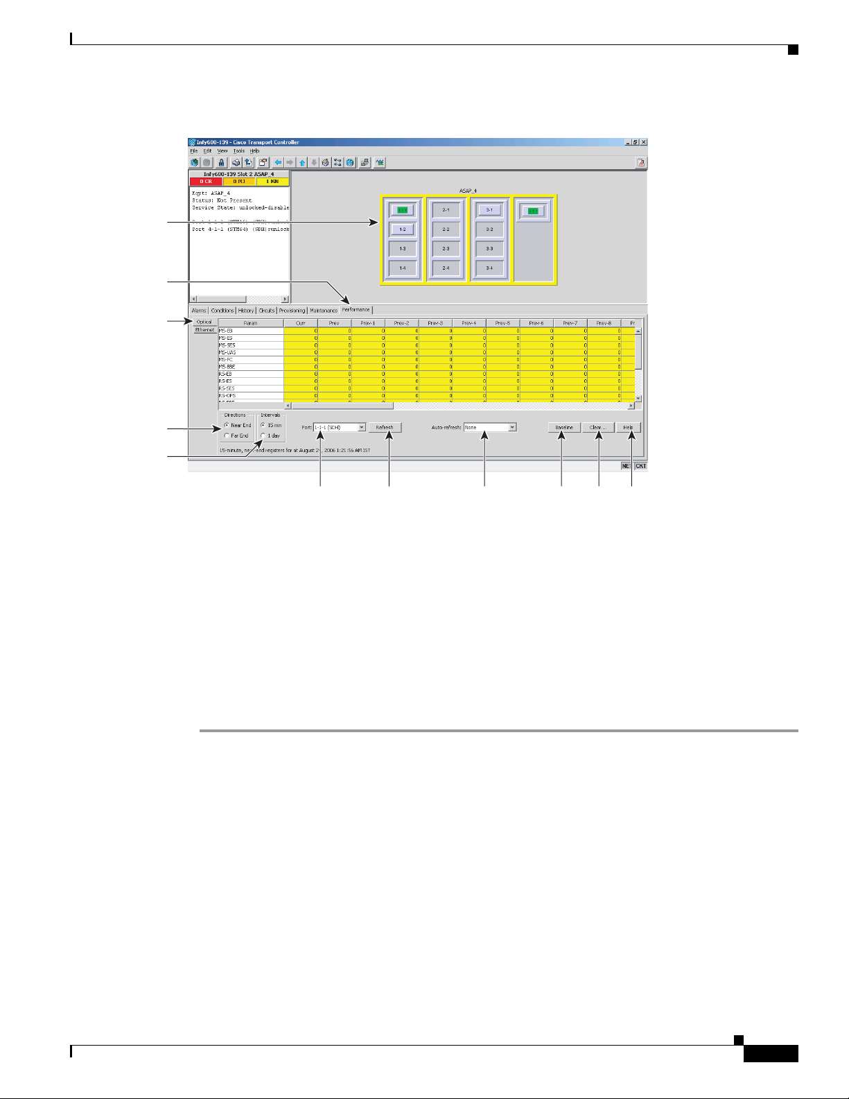
Step 2 Click the Performance > Optical tabs (Figure 18-3).
18-24
Cisco ONS 15600 SDH Procedure Guide, R8.0
October 2007
Page 25
Chapter 18 DLPs F300 to F399
Figure 18-3 Viewing ASAP Card Performance Monitoring Information
Card View
Performance tab
Optical tab
Directions
radio button
DLP- F327 View ASAP Ether Ports Statistics PM Parameters
Intervals
radio button
Por t
drop-down
list
Step 3
Step 4 Click Refresh.
Step 5 View the PM parameter names that appear in the Param column. The PM parameter values appear in the
In the Port drop-down list, choose the port that you want to monitor.
Refresh
button
Auto-
refresh
menu
Baseline
button
Clear
button
Curr (current) and Prev-n (previous) columns. For PM parameter definitions, refer to the “Performance
Monitoring” chapter in the Cisco ONS 15600 SDH Reference Manual.
Step 6 To monitor another port on a multiport card, choose another port from the Port drop-down list and click
Refresh.
Step 7 Return to your originating procedure (NTP).
DLP-F327 View ASAP Ether Ports Statistics PM Parameters
Purpose This task enables you to view current statistical PM counts on an ASAP
card and port to detect possible performance problems.
Tools/Equipment None
Prerequisite Procedures DLP-F181 Log into CTC, page 16-34
Required/As Needed As needed
Onsite/Remote Onsite or remote
Security Level Retrieve or higher
159525
Help
button
October 2007
Cisco ONS 15600 SDH Procedure Guide, R8.0
18-25
Page 26
DLP- F327 View ASAP Ether Ports Statistics PM Parameters
Step 1 In node view, double-click the card where you want to view PM counts. The card view appears.
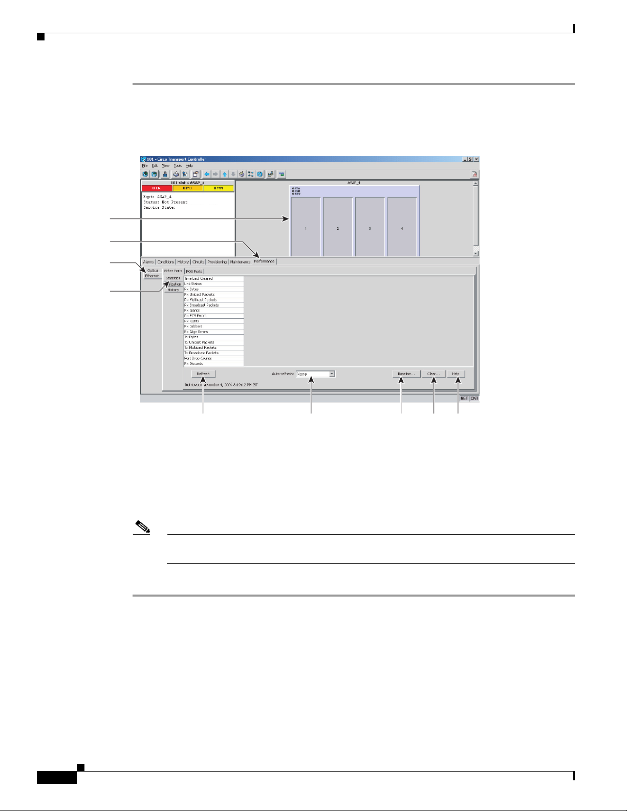
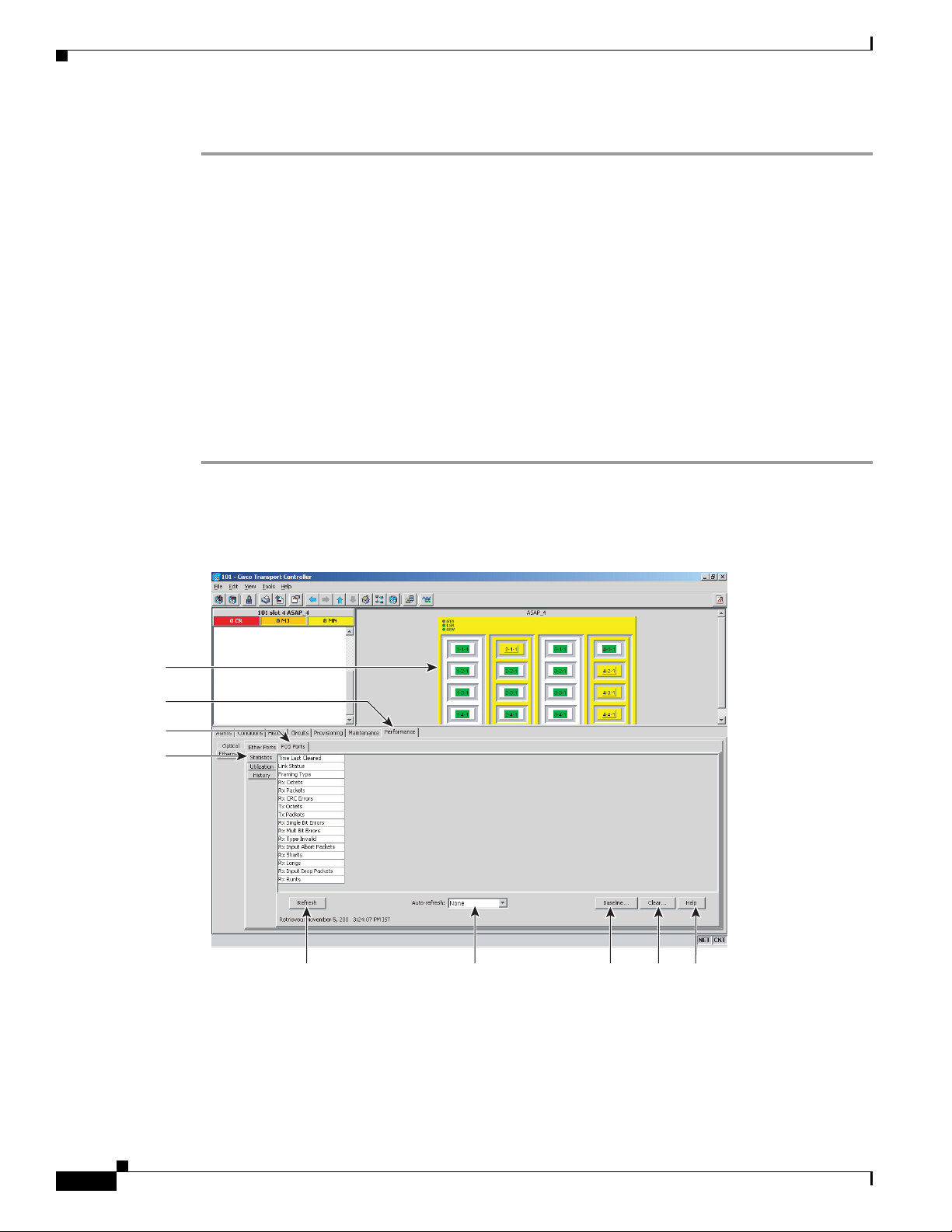
Step 2 Click the Performance > Ethernet > Ether Ports > Statistics tabs (Figure 18-4).
Figure 18-4 Ether Ports Statistics in the Card View Performance Window
Card View
Performance tab
Ethernet tab
Statistics tab
Chapter 18 DLPs F300 to F399
6
159544
Refresh
button
Auto-refresh
menu
Baseline
button
Clear
button
Help
button
Step 3 Click Refresh. Performance monitoring statistics appear for each port on the card.
Step 4 View the PM parameter names appear in the Param column. The current PM parameter values appear in
the Port # columns. For PM parameter definitions, refer to the “Performance Monitoring” chapter in the
Cisco ONS 15600 SDH Reference Manual.
Note To refresh, reset, or clear PM counts, see the “NTP-F184 Change the PM Display” procedure on
page 8-2.
Step 5 Return to your originating procedure (NTP).
18-26
Cisco ONS 15600 SDH Procedure Guide, R8.0
October 2007
Page 27
Chapter 18 DLPs F300 to F399
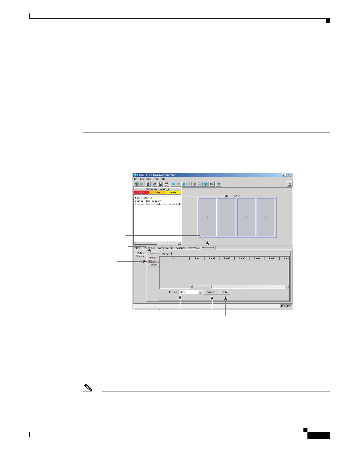
DLP- F328 View ASAP Ether Ports Utilization PM Parameters
DLP-F328 View ASAP Ether Ports Utilization PM Parameters
Purpose This task enables you to view line utilization PM counts on an ASAP
card and port to detect possible performance problems.
Tools/Equipment None
Prerequisite Procedures DLP-F181 Log into CTC, page 16-34
Required/As Needed As needed
Onsite/Remote Onsite or remote
Security Level Retrieve or higher
Step 1 In node view, double-click the ASAP card where you want to view PM counts. The card view appears.
Step 2 Click the Performance > Ethernet > Ether Ports > Utilization tabs (Figure 18-5).
Figure 18-5 Ether Ports Utilization in the Card View Performance Window
Card View
Performance tab
Ethernet tab
Utilization tab
159545
Interval
menu
Step 3
Step 4 View the Port # column for the port that you want to monitor.
Step 5 The transmit (Tx) and receive (Rx) bandwidth utilization values for the previous time intervals appear
Click Refresh. Performance monitoring utilization values appear for each port on the card.
Refresh
button
Help
button
in the Prev-n columns. For PM parameter definitions, refer to the “Performance Monitoring” chapter in
the Cisco ONS 15600 SDH Reference Manual.
October 2007
Note To refresh, reset, or clear PM counts, see the “NTP-F184 Change the PM Display” procedure on
page 8-2.
Cisco ONS 15600 SDH Procedure Guide, R8.0
18-27
Page 28
DLP- F329 View ASAP POS Ports Statistics PM Parameters
Step 6 Return to your originating procedure (NTP).
DLP-F329 View ASAP POS Ports Statistics PM Parameters
Purpose This task enables you to view POS port PM counts at selected time
intervals on an ASAP card and port to detect possible performance
problems.
Tools/Equipment None
Prerequisite Procedures DLP-F181 Log into CTC, page 16-34
Required/As Needed As needed
Onsite/Remote Onsite or remote
Security Level Retrieve or higher
Step 1 In node view, double-click the ASAP card where you want to view PM counts. The card view appears.
Step 2 Click the Performance > Ethernet > POS Ports > Statistics tabs (Figure 18-6).
Chapter 18 DLPs F300 to F399
Figure 18-6 POS Ports Statistics in the Card View Performance Window
Card View
Performance tab
POS tab
Statistics tab
6
Refresh
button
Auto-refresh
menu
Baseline
button
Clear
button
159562
Help
button
18-28
Step 3
Step 4 View the PM parameter names that appear in the Param column. The PM parameter values appear in the
Click Refresh. Performance monitoring statistics appear for each port on the card.
Port # columns. For PM parameter definitions refer to the “Performance Monitoring” chapter in the
Cisco ONS 15600 SDH Reference Manual.
Cisco ONS 15600 SDH Procedure Guide, R8.0
October 2007
Page 29
Chapter 18 DLPs F300 to F399
DLP- F330 View ASAP POS Ports Utilization PM Parameters
Note To refresh, reset, or clear PM counts, see the “NTP-F184 Change the PM Display” procedure on
page 8-2.
Step 5 Return to your originating procedure (NTP).
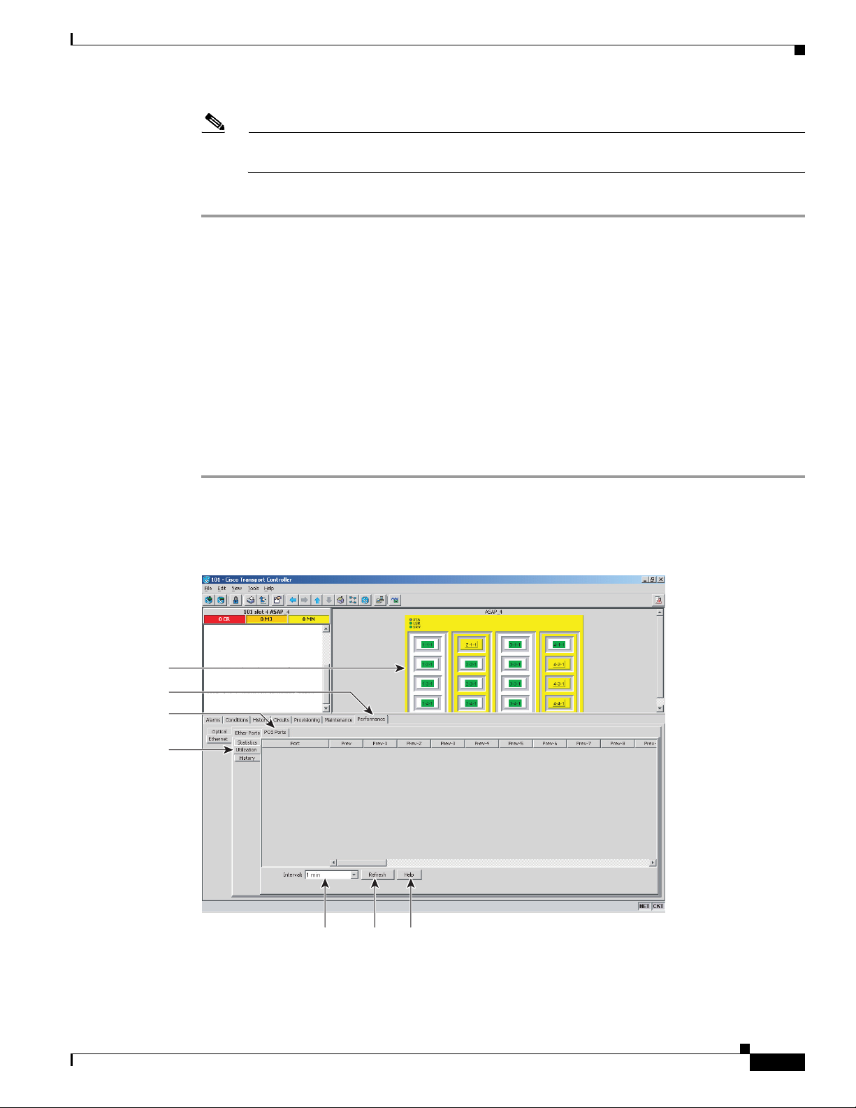
DLP-F330 View ASAP POS Ports Utilization PM Parameters
Purpose This task enables you to view POS port utilization PM counts on an
ASAP card and ports to detect possible performance problems.
Tools/Equipment None
Prerequisite Procedures DLP-F181 Log into CTC, page 16-34
Required/As Needed As needed
Onsite/Remote Onsite or remote
Security Level Retrieve or higher
Step 1 In node view, double-click the ASAP card where you want to view PM counts. The card view appears.
Step 2 Click the Performance > Ethernet > POS Ports > Utilization tabs (Figure 18-7).
Figure 18-7 POS Ports Utilization in the Card View Performance Window
Card View
Performance tab
POS tab
Utilization tab
October 2007
Step 3
159563
Interval
menu
Refresh
button
Help
button
Click Refresh. Performance monitoring utilization values for each port on the card appear.
Cisco ONS 15600 SDH Procedure Guide, R8.0
18-29
Page 30

DLP- F331 View ASAP POS Ports History PM Parameters
Step 4 View the Port # column for the port that you want to monitor.
Step 5 The Tx and Rx bandwidth utilization values for the previous time intervals appear in the Prev-n columns.
For PM parameter definitions, refer to the “Performance Monitoring” chapter in the
Cisco ONS 15600 SDH Reference Manual.
Note To refresh, reset, or clear PM counts, see the “NTP-F184 Change the PM Display” procedure on
page 8-2.
Step 6 Return to your originating procedure (NTP).
DLP-F331 View ASAP POS Ports History PM Parameters
Purpose This task enables you to view historical PM counts at selected time
intervals on an ASAP card and port to detect possible performance
problems.
Tools/Equipment None
Prerequisite Procedures DLP-F181 Log into CTC, page 16-34
Required/As Needed As needed
Onsite/Remote Onsite or remote
Security Level Retrieve or higher
Chapter 18 DLPs F300 to F399
Step 1 In node view, double-click the ASAP card where you want to view PM counts. The card view appears.
Step 2 Click the Performance > Ethernet > POS Ports > History tabs (Figure 18-8).
18-30
Cisco ONS 15600 SDH Procedure Guide, R8.0
October 2007
Page 31

Chapter 18 DLPs F300 to F399
DLP- F332 Change Node Access and PM Clearing Privilege
Figure 18-8 Ethernet POS Ports History in the Card View Performance Window
Card View
Performance
tab
POS tab
History tab
Refresh
Interval
menu
Step 3 Click Refresh. Performance monitoring statistics appear for each port on the card.
Step 4 View the PM parameter names that appear in the Param column. The PM parameter values appear in the
Por t
menu
button
Help
button
Prev-n columns. For PM parameter definitions, refer to the “Performance Monitoring” chapter in the
Cisco ONS 15600 SDH Reference Manual.
Note To refresh, reset, or clear PM counts, see the “NTP-F184 Change the PM Display” procedure on
page 8-2.
Step 5 Return to your originating procedure (NTP).
DLP-F332 Change Node Access and PM Clearing Privilege
Purpose This task provisions the physical access points and shell programs used to
connect to the ONS 15600 SDH and sets the user security level that can
clear node performance monitoring data.
Tools/Equipment None
Prerequisite Procedures DLP-F181 Log into CTC, page 16-34
Required/As Needed As needed
Onsite/Remote Onsite or remote
Security Level Superuser only
159564
October 2007
Cisco ONS 15600 SDH Procedure Guide, R8.0
18-31
Page 32

DLP- F332 Change Node Access and PM Clearing Privilege
Step 1 In node view, click the Provisioning > Security > Access tabs.
Step 2 In the Access area, provision the following:
• LAN access—Choose one of the following options to set the access paths to the node:
–
No LAN Access—Allows access to the node only through data communications channel (DCC)
connections. Access through the TSC RJ-45 port and backplane is not permitted.
–
Front only—Allows access through the TSC RJ-45 port. Access through the DCC and the
backplane is not permitted.
–
Backplane only—Allows access through DCC connections and the backplane. Access through
the TSC RJ-45 port is not allowed.
–
Front and Backplane—Allows access through DCC, TSC RJ-45, and backplane connections.
• Restore Timeout—Sets a time delay for enabling of front and backplane access when DCC
connections are lost and “DCC only” is chosen in LAN Access. Front and backplane access is
enabled after the restore timeout period has passed. Front and backplane access is disabled as soon
as DCC connections are restored.
Step 3 In the Shell Access area, set the shell program used to access the node:
• Access State: Allows you to set the shell program access mode to Disable (disables shell access),
Non-Secure, or Secure. Secure mode allows access to the node using the Secure Shell (SSH)
program. SSH is a terminal-remote host Internet protocol that uses encrypted links.
Chapter 18 DLPs F300 to F399
• Telnet Port: Allows access to the node using the Telnet port. Telnet is the terminal-remote host
Internet protocol developed for the Advanced Agency Research Project Network (ARPANET).
Port 23 is the default.
• Enable Shell Password: If checked, enables the SSH password. To disable the password, you must
uncheck the check box and click Apply. You must type the password in the confirmation dialog box
and click OK to disable it.
Step 4 In the TL1 Access area, select the desired level of TL1 access. Disabled completely disables all TL1
access; Non-Secure, and Secure allows access using SSH.
Step 5 In the PM Clearing Privilege field, choose the minimum security level that can clear node PM data:
PROVISIONING or SUPERUSER.
Step 6 Select the Enable Craft Port check box to turn on the shelf controller serial ports.
Step 7 Select the EMS access state from the list. Available states are Non-Secure and Secure (allows access
using SSH).
In the TCC CORBA (IIOP/SSLIOP) Listener Port area, choose a listener port option:
• Default - TCC Fixed—Uses Port 57790 to connect to ONS 15454s on the same side of the firewall
or if no firewall is used (default). This option can be used for access through a firewall if Port 57790
is open.
• Standard Constant—Uses Port 683 (IIOP) or Port 684 (SSLIOP), the Common Object Request
Broker Architecture (CORBA) default port number.
• Other Constant—If the default port is not used, type the Internet Inter-ORB Protocol (IIOP) or
SSLIOP port specified by your firewall administrator.
Step 8 In the SNMP Access area, set the Simple Network Management Protocol (SNMP) access state to
Non-Secure or Disabled (disables SNMP access).
18-32
Step 9 Click Apply.
Cisco ONS 15600 SDH Procedure Guide, R8.0
October 2007
Page 33

Chapter 18 DLPs F300 to F399
Step 10 Return to your originating procedure (NTP).
DLP-F333 Install the ASAP Carrier Modules
Purpose This procedure explains how to install the carrier modules in the
ONS 15600 SDH shelf.
Tools/Equipment ASAP carrier modules
Prerequisite Procedures NTP-F118 Install the Common Control Cards, page 2-2
Required/As Needed As needed
Onsite/Remote Onsite
Security Level None
DLP- F333 Install the ASAP Carrier Modules
Warning
Caution Always use the supplied ESD wristband when working with a powered ONS 15600 SDH. Plug the
During this procedure, wear grounding wrist straps to avoid ESD damage to the card. Do not directly
touch the midplane with your hand or any metal tool, or you could shock yourself.
Statement 181
wristband cable into the ESD jack located on the lower-left outside edge of the shelf.
Warning
Warning
Warning
Note For information about the ASAP card, refer to the Cisco ONS 15600 SDH Reference Manual.
Class 1 laser product.
Invisible laser radiation may be emitted from the end of the unterminated fiber cable or connector. Do
not view directly with optical instruments. Viewing the laser output with certain optical instruments
(for example, eye loupes, magnifiers, and microscopes) within a distance of 100 mm may pose an eye
hazard.
Use of controls, adjustments, or performing procedures other than those specified may result in
hazardous radiation exposure.
Statement 1056
Statement 1008
Statement 1057
October 2007
Step 1 Remove the carrier module from the box and antistatic sleeve.
Caution Setting an ASAP carrier module on its connectors can cause damage to the connectors.
Step 2 Slide the module along the top and bottom guide rails into the correct slot: Slots 1 to 4 and 11 to 14 are
available for traffic cards. Insert the card until it contacts the backplane.
Step 3 Close the ejectors.
Cisco ONS 15600 SDH Procedure Guide, R8.0
18-33
Page 34

DLP- F334 Verify Pass-Through Circuits
Step 4 Verify the LED activity on the card faceplate:
1. The STAT, SRV, and LASER ON LEDs turn on for 20 seconds.
2. The STAT LED blinks and the other LEDs turn on for 30 to 50 seconds.
3. All LEDs blink once and the SRV and LASER ON LEDs illuminate.
Note If the LEDs do not turn on, check that the power breakers on the power distribution unit
Note If you insert a card into a slot provisioned for a different card, all red LEDs turn on and you
Step 5 After you have logged into CTC, verify that the card appears in the correct slot on the CTC node view.
See Chapter 3, “Connect the PC and Log into the GUI” for CTC information and setup instructions.
Step 6 Return to your originating procedure (NTP).
Chapter 18 DLPs F300 to F399
(PDU) are on. Refer to the Cisco ONS 15600 SDH Troubleshooting Guide.
will see a mismatched equipment (MEA) alarm for that slot when you open Cisco Transport
Controller (CTC).
DLP-F334 Verify Pass-Through Circuits
Purpose This task verifies that circuits passing through a node that will be removed
enter and exit the node on the same virtual container (VC).
Tools/Equipment None
Prerequisite Procedures DLP-F181 Log into CTC, page 16-34
Required/As Needed As needed
Onsite/Remote Onsite or remote
Security Level Provisioning or higher
Step 1 In the Circuits window, choose a circuit that passes through the node that will be removed and click Edit.
Step 2 In the Edit Circuits window, check Show Detailed Map.
Step 3 Verify that the VC mapping on the node’s east and west ports is the same. For example, if a circuit is
mapping on the west port s2/p1/VC4-1 (Slot 2, Port 1, VC4-1), verify that the mapping is VC4-1 on the
east port. If the circuit displays different VCs on the east and west ports, write down the name of the
circuit.
Step 4 Repeat Steps 1 to 3 for each circuit in the Circuits tab.
Step 5 Delete and recreate each circuit recorded in Step 3 that entered/exited the node on different VCs. To
delete the circuit, see the “DLP-F293 Delete Circuits” task on page 17-81. To create the circuit, see
Chapter 6, “Create Circuits.”
Step 6 Return to your originating procedure (NTP).
18-34
Cisco ONS 15600 SDH Procedure Guide, R8.0
October 2007
Page 35

Chapter 18 DLPs F300 to F399
DLP-F335 Preprovision an SFP
Purpose This procedure preprovisions Small Form-factor Pluggables (SFPs), which
Tools/Equipment None
Prerequisite Procedures None
Required/As Needed As needed
Onsite/Remote Onsite or remote
Security Level Provisioning or higher
Note If you preprovision a multirate SFP, you must next select the line rate using the “DLP-F390 Provision
an Optical Line Rate and Wavelength” task on page 18-103.
DLP- F335 Preprovision an SFP
are referred to as pluggable port modules (PPMs) in CTC. Cisco-approved
STM-1, STM-4, STM-16, Ethernet, and multirate PPMs are compatible
with the ONS 15600 SDH. See the Cisco ONS 15600 SDH Reference
Manual for a list of acceptable SFPs.
Step 1 Complete the “DLP-F181 Log into CTC” task on page 16-34 to log into an ONS 15600 SDH on the
network.
Step 2 Click the Alarms tab:
a. Verify that the alarm filter is not turned on. See the “DLP-F288 Disable Alarm Filtering” task on
page 17-78 as necessary.
b. Verify that no unexplained conditions appear on the network. If unexplained conditions appear,
resolve them before continuing. Refer to the Cisco ONS 15600 SDH Troubleshooting Guide for
procedures to clear alarms.
c. Complete the “DLP-F379 Export CTC Data” task on page 18-88 to export alarm and condition
information.
Step 3 In node view, double-click the ASAP card where you want to provision PPM settings.
Step 4 Click the Provisioning > Pluggable Port Modules tabs.
Step 5 In the Pluggable Port Modules pane, click Create. The Create PPM dialog box appears.
Step 6 In the Create PPM dialog box, complete the following:
• PPM—Click the slot number where you want to preprovision the SFP from the drop-down list.
• PPM Type—Click the number of ports supported by your SFP from the drop-down list. If only one
port is supported, PPM (1 port) is the only option.
Step 7 Click OK. The newly created port appears on the Pluggable Port Modules pane. The row on the
Pluggable Port Modules pane turns light blue and the Actual Equipment Type column lists the
preprovisioned PPM as unknown until the actual SFP is installed. After the SFP is installed, the row on
the pane turns white and the column lists the equipment name.
Step 8 Verify that the PPM appears in the list on the Pluggable Port Modules pane. If it does not, repeat
Steps 5 through 8.
Step 9 On the Provisioning tab, click the Line subtab. If applicable for the PPM you are preprovisioning, use
the Reach and Wavelength columns to configure these parameters as needed.
October 2007
Cisco ONS 15600 SDH Procedure Guide, R8.0
18-35
Page 36

DLP- F336 Print CTC Data
Note Only the parameters that are editable for the PPMs on a particular platform type are
provisionable. For example, some platforms may not have PPMs with configurable wavelengths
or reaches. In this case, wavelength and reach are not provisionable.
Step 10 Repeat Steps 1 to 10 create a second PPM.
Step 11 Click OK.
Step 12 When you are ready to install the SFP, complete the “DLP-F387 Install an SFP/XFP” task on
page 18-100.
Step 13 Return to your originating procedure (NTP).
DLP-F336 Print CTC Data
Purpose This task prints CTC windows and CTC table data such as alarms and
Equipment/Tools A printer must be connected to the CTC computer
Prerequisite Procedures DLP-F181 Log into CTC, page 16-34
Required/As Needed As needed
Onsite/Remote Onsite or remote
Security Level Retrieve or higher
Chapter 18 DLPs F300 to F399
inventory.
Step 1 From the CTC File menu, click Print.
Step 2 In the Print dialog box (Figure 18-9), choose an option:
• Entire Frame—Prints the entire CTC window including the graphical view of the card, node, or
network.
• Tabbed View—Prints the lower half of the CTC window.
• Table Contents—Prints CTC data in table format; this option is only available for CTC table data
(see Table A-6 on page A-10). It does not apply to:
• Provisioning > General window
• Provisioning > SNMP window
• Provisioning > Timing window
• Provisioning > Network > Internal Subnet window
• Provisioning > Network > General window
• Provisioning > Security > Policy window
• Provisioning > Security > Access window
• Provisioning > Security > Legal Disclaimer window
• Provisioning > OSI > Main Setup window
• Provisioning > OSI > TARP > Config window
• Maintenance > Database window
18-36
Cisco ONS 15600 SDH Procedure Guide, R8.0
October 2007
Page 37

Chapter 18 DLPs F300 to F399
DLP- F337 View ASAP Ether Ports History PM Parameters
• Maintenance > Protection window
• Maintenance > Diagnostic window
• Maintenance > Preferred Copy window
• Maintenance > Timing > Source window
The Table Contents option prints all the data contained in a table and the table column headings. For
example, if you print the History window Table Contents view, you print all data included in the
table whether or not items appear in the window.
Tip When you print using the Tabbed View option, it can be difficult to distinguish whether the
printout applies to the network, node, or card view. To determine the view, compare the tabs on
the printout. The network, node, and card views are identical except that network view does not
contain an Inventory or Performance tab.
Figure 18-9 Selecting CTC Data for Print
Step 3
Step 4 In the Windows Print dialog box, choose a printer and click OK.
Step 5 Return to your originating procedure (NTP).
Click OK.
DLP-F337 View ASAP Ether Ports History PM Parameters
Purpose This task enables you to view historical PM counts at selected time
intervals on an ASAP card and port to detect possible performance
problems.
Tools/Equipment None
Prerequisite Procedures DLP-F181 Log into CTC, page 16-34
Required/As Needed As needed
Onsite/Remote Onsite or remote
Security Level Retrieve or higher
Step 1 In node view, double-click the ASAP card where you want to view PM counts. The card view appears.
Step 2 Click the Performance > Ethernet > Ether Ports > History tabs (Figure 18-10).
October 2007
Cisco ONS 15600 SDH Procedure Guide, R8.0
18-37
Page 38

DLP- F338 Create a Two-Fiber MS-SPRing Using the MS-SPRing Wizard
Figure 18-10 Ethernet Ether Ports History on the Card View Performance Window
unlocked-disabled, auto
Card View
Performance tab
Ethernet tab
History tab
Chapter 18 DLPs F300 to F399
159561
Interval
menu
Step 3
Step 4 View the PM parameter names that appear in the Param column. The PM parameter values appear in the
Click Refresh. Performance monitoring statistics for each port on the card appear.
Por t
menu
Refresh
button
Help
button
Prev-n columns. For PM parameter definitions, refer to the “Performance Monitoring” chapter in the
Cisco ONS 15600 SDH Reference Manual.
Note To refresh, reset, or clear PM counts, see the NTP-F184 Change the PM Display, page 8-2.
Step 5 Return to your originating procedure (NTP).
DLP-F338 Create a Two-Fiber MS-SPRing Using the MS-SPRing Wizard
Purpose This task creates a two-fiber multiplex section-shared protection ring
(MS-SPRing) at each MS-SPRing-provisioned node using the CTC
MS-SPRing wizard. The MS-SPRing wizard checks to see that each node
is ready for MS-SPRing provisioning, then provisions all the nodes at one
time.
Tools/Equipment None
Prerequisite Procedures DLP-F293 Delete Circuits, page 17-81
18-38
DLP-F181 Log into CTC, page 16-34
Required/As Needed As needed
Cisco ONS 15600 SDH Procedure Guide, R8.0
October 2007
Page 39

Chapter 18 DLPs F300 to F399
Step 1 From the View menu, choose Go to Network View.
Step 2 Click the Provisioning > MS-SPRing tabs.
Step 3 Click Create MS-SPRing.
Step 4 In the MS-SPRing Creation dialog box, set the MS-SPRing properties:
Step 5 Click Next. If the network graphic appears, go to Step 6.
DLP- F338 Create a Two-Fiber MS-SPRing Using the MS-SPRing Wizard
Onsite/Remote Onsite or remote
Security Level Provisioning or higher
• Ring Type—Choose two-fiber.
• Speed—Choose the MS-SPRing ring speed: STM-4, STM-16, or STM-64. The speed must match
the STM-N speed of the MS-SPRing trunk (span) ports.
• Ring Name—Assign a ring name. The name can be from 1 to 6 characters in length. Any
alphanumeric string is permissible, and uppercase and lowercase letters can be combined. Do not
use the character string All in either uppercase or lowercase letters; this is a TL1 keyword and will
be rejected. Do not choose a name that is already assigned to another MS-SPRing.
• Reversion time—Set the amount of time that will pass before the traffic reverts to the original
working path following a ring switch. The default is 5 minutes. Ring reversion can be set to Never.
If CTC determines that an MS-SPRing cannot be created, for example, not enough optical cards are
installed or it finds circuits with SNCP selectors, a “Cannot Create MS-SPRing” message appears. If this
occurs, complete the following steps:
a. Click OK.
b. In the Create MS-SPRing window, click Excluded Nodes. Review the information explaining why
the MS-SPRing could not be created, then click OK.
c. Depending on the problem, click Back to start over or click Cancel to cancel the operation.
d. Complete the NTP-F147 Provision MS-SPRing Nodes, page 5-6, making sure all steps are
completed accurately, then start this procedure again.
Step 6 In the network graphic, double-click an MS-SPRing span line. If the span line is DCC-connected to other
MS-SPRing ports that constitute a complete ring, the lines turn blue. If the lines do not form a complete
ring, double-click the span lines until a complete ring is formed. When the ring is DCC-connected, go
to Step 7.
Step 7 Click Finish. If the MS-SPRing window appears with the MS-SPRing you created, go to Step 8. If a
“Cannot Create MS-SPRing” or “Error While Creating MS-SPRing” message appears:
a. Click OK.
b. In the Create MS-SPRing window, click Excluded Nodes. Review the information explaining why
the MS-SPRing could not be created, then click OK.
c. Depending on the problem, click Back to start over or click Cancel to cancel the operation.
d. Complete the NTP-F147 Provision MS-SPRing Nodes, page 5-6, making sure all steps are
completed accurately, then start this procedure again.
Note Some or all of the following alarms might briefly appear during MS-SPRing setup:
E-W-MISMATCH, RING-MISMATCH, APSCIMP, APSCDFLTK, and MSSP-OOSYNC.
October 2007
Step 8 Verify the following:
Cisco ONS 15600 SDH Procedure Guide, R8.0
18-39
Page 40

DLP- F339 Create a Two-Fiber MS-SPRing Manually
• On the network view graphic, a green span line appears between all MS-SPRing nodes.
• All E-W-MISMATCH, RING-MISMATCH, APSCIMP, APSCDFLTK, and MSSP-OOSYNC
alarms are cleared. See the Cisco ONS 15600 SDH Troubleshooting Guide for alarm troubleshooting
procedures.
Note The numbers in parentheses after the node name are the MS-SPRing node IDs assigned by CTC.
Every ONS 15600 SDH in an MS-SPRing is given a unique node ID, 0 through 31. To change
it, complete the “DLP-F340 Change an MS-SPRing Node ID” task on page 18-41.
Step 9 Return to your originating procedure (NTP).
DLP-F339 Create a Two-Fiber MS-SPRing Manually
Purpose This tasks creates a two-fiber MS-SPRing at each MS-SPRing-provisioned
node without using the MS-SPRing wizard.
Tools/Equipment None
Prerequisite Procedures NTP-F147 Provision MS-SPRing Nodes, page 5-6
Chapter 18 DLPs F300 to F399
DLP-F181 Log into CTC, page 16-34
Required/As Needed Required
Onsite/Remote Onsite or remote
Security Level Provisioning or higher
Step 1 In node view, click the Provisioning > MS-SPRing tabs.
Step 2 Click Create.
Step 3 In the Suggestion dialog box, click OK.
Step 4 In the Create MS-SPRing dialog box, set the MS-SPRing properties:
• Ring Type—Choose two-fiber.
• Ring Name—Assign a ring name. You must use the same ring name for each node in the
MS-SPRing. Any alphanumeric character string is permissible, and uppercase and lowercase letters
can be combined. Do not use the character string All in either uppercase or lowercase letters; this is
a TL1 keyword and will be rejected. Do not choose a name that is already assigned to another
MS-SPRing.
• Node ID—Choose a Node ID from the drop-down list (0 through 31). The Node ID identifies the
node to the MS-SPRing. Nodes in the same MS-SPRing must have unique Node IDs.
• Reversion time—Set the amount of time that will pass before the traffic reverts to the original
working path. The default is 5 minutes. All nodes in a MS-SPRing must have the same reversion
time setting.
• West Line—Assign the west MS-SPRing port for the node from the drop-down list.
18-40
Note The east and west ports must match the fiber connections and DCC terminations set up in
the “NTP-F147 Provision MS-SPRing Nodes” procedure on page 5-6.
Cisco ONS 15600 SDH Procedure Guide, R8.0
October 2007
Page 41

Chapter 18 DLPs F300 to F399
Step 5 Click OK.
Step 6 From the View menu, choose Go to Other Node.
Step 7 In the Select Node dialog box, choose the next node that you want to add to the MS-SPRing.
Step 8 Repeat Steps 1 through 7 at each node that you want to add to the MS-SPRing. When all nodes have been
Step 9 From the View menu, choose Go to Network View. After 10 to 15 seconds, verify the following:
Step 10 Return to your originating procedure (NTP).
DLP- F340 Change an MS-SPRing Node ID
• East Line—Assign the east MS-SPRing port for the node from the drop-down list.
Note Some or all of the following alarms will appear until all the MS-SPRing nodes are provisioned:
E-W MISMATCH, RING MISMATCH, APSCIMP, APSDFLTK, and MSSP-OOSYNC. The
alarms will clear after you configure all the nodes in the MS-SPRing.
added, continue with Step 9.
• A green span line appears between all BLSR nodes.
• All E-W MISMATCH, RING MISMATCH, APSCIMP, APSDFLTK, and MSSP-OOSYNC alarms
are cleared.
DLP-F340 Change an MS-SPRing Node ID
Purpose This task changes an MS-SPRing node ID.
Tools/Equipment None
Prerequisite Procedures DLP-F181 Log into CTC, page 16-34
Required/As Needed As needed
Onsite/Remote Onsite or remote
Security Level Provisioning or higher
Step 1 From the View menu, choose Go to Network View.
Step 2 On the network map, double-click the node with the node ID you want to change.
Step 3 From node view, click the Provisioning > MS-SPRing tabs.
Step 4 Choose a Node ID number. Do not choose a number already assigned to another node in the same
MS-SPRing.
Step 5 Click Apply.
Step 6 Return to your originating procedure (NTP).
October 2007
Cisco ONS 15600 SDH Procedure Guide, R8.0
18-41
Page 42

DLP- F341 MS-SPRing Exercise Ring Test
DLP-F341 MS-SPRing Exercise Ring Test
Purpose This task tests the MS-SPRing ring functionality without switching traffic.
Ring exercise conditions (including the K-byte pass-through) are reported
and cleared within 10 to 15 seconds.
Tools/Equipment None
Prerequisite Procedures DLP-F181 Log into CTC, page 16-34
Required/As Needed As needed
Onsite/Remote Onsite
Security Level Provisioning or higher
Step 1 From the View menu, choose Go To Network View.
Step 2 Click the Provisioning > MS-SPRing tabs.
Step 3 Click the row of the MS-SPRing you will exercise, then click Edit.
Step 4 Exercise the west port:
a. Right-click the west port of any MS-SPRing node and choose Set West Protection Operation. (To
move a graphic icon, press Ctrl while you drag and drop it to a new location.)
Chapter 18 DLPs F300 to F399
Note For two-fiber MS-SPRings, the squares on the node icons represent the MS-SPRing working
and protect channels. You can right-click either channel.
b. In the Set West Protection Operation dialog box, choose EXERCISE RING from the drop-down
list.
c. Click OK.
d. In the Confirm MS-SPRing Operation dialog box, click Yes .
On the network view graphic, an E appears on the working MS-SPRing channel where you invoked
the protection switch. The E will appear for 10 to 15 seconds, then disappear.
Step 5 Exercise the east port:
a. Right-click the east port of any MS-SPRing node and choose Set East Protection Operation.
Note For two-fiber MS-SPRings, the squares on the node icons represent the MS-SPRing working
and protect channels. You can right-click either channel.
b. In the Set East Protection Operation dialog box, choose EXERCISE RING from the drop-down list.
c. Click OK.
d. In the Confirm MS-SPRing Operation dialog box, click Yes .
On the network view graphic, an E appears on the MS-SPRing channel where you invoked the
exercise. The E will appear for 10 to 15 seconds, then disappear.
Step 6 In the Cisco Transport Controller window, click the History tab. Verify that an Exercising Ring
Successfully (EXERCISING-RING) condition appears for the node where you exercised the ring. Other
conditions that appear include KB-PASSTHR and FE-EXERCISING-RING.
18-42
Cisco ONS 15600 SDH Procedure Guide, R8.0
October 2007
Page 43

Chapter 18 DLPs F300 to F399
If you do not see any MS-SPRing exercise conditions, click the Filter button and verify that filtering is
not turned on. Also, check that alarms and conditions are not suppressed for a node or MS-SPRing drop
cards. See the “NTP-F195 Suppress and Restore Alarm Reporting” procedure on page 9-7 for more
information.
Step 7 Click the Alarms tab.
a. Verify that the alarm filter is not on. See the “DLP-F288 Disable Alarm Filtering” task on
page 17-78 for instructions.
b. Verify that no unexplained alarms appear on the network. If unexplained alarms appear, resolve
them before continuing. Refer to the Cisco ONS 15600 Troubleshooting Guide for alarm clearing
procedures.
Step 8 From the File menu, choose Close to close the MS-SPRing window.
Step 9 Return to your originating procedure (NTP).
DLP-F342 MS-SPRing Switch Test
DLP- F342 MS-SPRing Switch Test
Purpose This task verifies that protection switching is working correctly in an
MS-SPRing.
Tools/Equipment None
Prerequisite Procedures DLP-F181 Log into CTC, page 16-34
Required/As Needed Required
Onsite/Remote Onsite
Security Level Provisioning or higher
Step 1 From the View menu, choose Go to Network View.
Step 2 Click the Provisioning > MS-SPRing tabs.
Step 3 Click the row of the MS-SPRing you will switch, then click Edit.
Step 4 Initiate a Force Ring switch on the west port:
a. Right-click any MS-SPRing node west port and choose Set West Protection Operation. (To move
a graphic icon, click it, then press Ctrl while you drag and drop it to a new location.)
Note For two-fiber MS-SPRings, the squares on the node icons represent the MS-SPRing working
and protect channels. You can right-click either channel.
b. In the Set West Protection Operation dialog box, choose FORCE RING from the drop-down list.
c. Click OK.
October 2007
d. Click Ye s in the two Confirm MS-SPRing Operation dialog boxes that appear.
On the network view graphic, an F appears on the MS-SPRing channel where you invoked the Force
Ring switch. The MS-SPRing span lines turn purple where the switch was invoked, and all span lines
between other MS-SPRing nodes turn green.
Cisco ONS 15600 SDH Procedure Guide, R8.0
18-43
Page 44

DLP- F342 MS-SPRing Switch Test
Step 5 Verify the conditions:
a. Click the Conditions tab.
b. Click Retrieve.
c. Verify that the following conditions are reported on the node where you invoked the Force Ring
switch on the west port:
• FORCE-REQ-RING—A Force Switch Request On Ring condition is reported against the span’s
• RING-SW-EAST—A Ring Switch Active on the east side condition is reported against the
Note Make sure the Filter button in the lower right corner of the window is off. Click the Node
d. Verify that the following conditions are reported on the node that is connected to the West line of
the node where you performed the switch:
• FE-FRCDWKSWPR-RING—A Far-End Working Facility Forced to Switch to Protection
• RING-SW-WEST—A Ring Switch Active on the west side condition is reported against the
Step 6 (Optional) If you remapped the K3 byte to run an ONS 15600 SDH MS-SPRing through third-party
equipment, check the following condition. Verify a FULLPASSTHR-BI condition reported on other
nodes that are not connected to the west side of the node where you invoked the Force Ring switch.
Chapter 18 DLPs F300 to F399
working slot on the west side of the node.
working span on the east side of the node.
column to sort conditions by node.
condition is reported against the working span on the east side of the node.
working span on the west side of the node.
Step 7 Verify the MS-SPRing line status on each node:
a. From the View menu, choose Go to Node View.
b. Click the Maintenance > MS-SPRing tabs.
c. Verify the following:
• The line states are shown as Stby/Stby on the west side of the node and Act/Act on the east side
of the node where you invoked the Force Ring switch.
• The line states are shown as Stby/Stby on the east side of the node and Act/Act on the west side
of the node that is connected to the west line of the node where you invoked the Force Ring
switch.
• The line states are shown as Act/Act on both the east and west sides of the remaining nodes in
the ring.
Step 8 From the View menu, choose Go to Network View.
Step 9 Click the Alarms tab.
a. Verify that the alarm filter is not on. See the “DLP-F288 Disable Alarm Filtering” task on
page 17-78 for instructions.
b. Verify that no unexplained alarms appear on the network. If unexplained alarms appear, resolve
them before continuing. Refer to the Cisco ONS 15600 Troubleshooting Guide for procedures.
Step 10 Display the MS-SPRing window where you invoked the Force Ring switch (the window might be hidden
by the CTC window).
18-44
Cisco ONS 15600 SDH Procedure Guide, R8.0
October 2007
Page 45

Chapter 18 DLPs F300 to F399
Step 11 Clear the switch on the west port:
Step 12 In network view, click the Conditions tab. Verify that all conditions raised in this procedure are cleared
Step 13 Verify the MS-SPRing line status on each node:
DLP- F342 MS-SPRing Switch Test
a. Right-click the west port of the MS-SPRing node where you invoked the Force Ring switch and
choose Set West Protection Operation.
b. In the Set West Protection Operation dialog box, choose CLEAR from the drop-down list.
c. Click OK.
d. Click Ye s in the Confirm MS-SPRing Operation dialog box.
On the network view graphic, the Force Ring switch is removed, the F indicating the switch is
removed, and the span lines between MS-SPRing nodes will be purple and green. The span lines
might take a few moments to change color.
from the network. If unexplained conditions appear, resolve them before continuing.
a. From the View menu, choose Go to Node View.
a. Click the Maintenance > MS-SPRing tabs.
b. Verify that the line states are shown as Act/Stby on both the east and west sides of each node in the
ring.
Step 14 Initiate a Force Ring switch on the east port:
a. Right-click the east port of MS-SPRing node and choose Set East Protection Operation.
b. In the Set East Protection Operation dialog box, choose FORCE RING from the drop-down list.
c. Click OK.
d. Click Ye s in the two Confirm MS-SPRing Operation dialog boxes that appear.
On the network view graphic, an F appears on the working MS-SPRing channel where you invoked
the Force Ring switch. The MS-SPRing span lines are purple where the Force Ring switch was
invoked, and all span lines between other MS-SPRing nodes are green. The span lines might take a
few moments to change color.
Step 15 Verify the conditions:
a. Click the Conditions tab.
b. Click Retrieve.
c. Verify that the following conditions are reported on the node where you invoked the Force Ring
switch on the east port:
• FORCE-REQ-RING—A Force Switch Request On Ring condition is reported against the span’s
working slot on the east side of the node.
• RING-SW-WEST—A Ring Switch Active on the west side condition is reported against the
working span on the east side of the node.
October 2007
Note Make sure the Filter button in the lower right corner of the window is off. Click the Node
column to sort conditions by node.
d. Verify that the following conditions are reported on the node that is connected to the East line of the
node where you performed the switch:
• FE-FRCDWKSWPR-RING—A Far-End Working Facility Forced to Switch to Protection
condition is reported against the working span on the west side of the node.
Cisco ONS 15600 SDH Procedure Guide, R8.0
18-45
Page 46

DLP- F342 MS-SPRing Switch Test
• RING-SW-EAST—A Ring Switch Active on the east side condition is reported against the
Step 16 (Optional) If you remapped the K3 byte to run an ONS 15600 SDH MS-SPRing through third-party
equipment, verify a FULLPASSTHR-BI condition reported on other nodes that are not connected to the
west side of the node where you invoked the Force Ring switch.
Step 17 Verify the MS-SPRing line status on each node:
a. From the View menu, choose Go to Node View.
b. Click the Maintenance > MS-SPRing tabs. Verify the following:
• The line states are shown as Stby/Stby on the east side of the node and Act/Act on the west side
• The line states are shown as Stby/Stby on the west side of the node and Act/Act on the east side
• The line states are shown as Act/Act on both east and west sides of the remaining nodes in the
Step 18 From the View menu, choose Go To Network View.
Step 19 Click the Alarms tab.
a. Verify that the alarm filter is not on. See the “DLP-F288 Disable Alarm Filtering” task on
page 17-78 for instructions.
Chapter 18 DLPs F300 to F399
working span on the west side of the node.
of the node where you invoked the Force Ring switch.
of the node that is connected to the east line of the node where you invoked the Force Ring
switch.
ring.
b. Verify that no unexplained alarms appear on the network. If unexplained alarms appear, resolve
them before continuing. Refer to the Cisco ONS 15600 Troubleshooting Guide for procedures.
Step 20 Display the MS-SPRing window where you invoked the Force Ring switch (the window might be hidden
by the CTC window).
Step 21 Clear the switch on the east port:
a. Right-click the east port of the MS-SPRing node where you invoked the Force Ring switch and
choose Set East Protection Operation.
b. In the Set East Protection Operation dialog box, choose CLEAR from the drop-down list.
c. Click OK.
d. Click Ye s in the Confirm MS-SPRing Operation dialog box.
On the network view graphic, the Force Ring switch is removed, the F indicating the switch is
removed, and the span lines between MS-SPRing nodes will be purple and green. The span lines
might take a few moments to change color.
Step 22 From network view, click the Conditions tab. Verify that all conditions raised in this procedure are
cleared from the network. If unexplained conditions appear, resolve them before continuing.
Step 23 Verify the MS-SPRing line status on each node:
a. From the View menu, choose Go to Node View.
b. Click the Maintenance > MS-SPRing tabs.
c. Verify that the line states are shown as Act/Stby on both the east and west sides of each node in the
ring.
Step 24 From the File menu, choose Close to close the MS-SPRing window.
18-46
Step 25 Return to your originating procedure (NTP).
Cisco ONS 15600 SDH Procedure Guide, R8.0
October 2007
Page 47

Chapter 18 DLPs F300 to F399
DLP-F343 Provision an STM-N Circuit Route
Purpose This task provisions the circuit route for manually routed STM-N circuits.
Tools/Equipment None
Prerequisite Procedures DLP-F181 Log into CTC, page 16-34
The Circuit Creation Wizard must be open.
Required/As Needed As needed
Onsite/Remote Onsite or remote
Security Level Provisioning or higher
Step 1 In the Circuit Creation wizard in the Route Review/Edit area, click the source node icon if it is not
already selected.
Step 2 Starting with a span on the source node, click the arrow of the span you want the circuit to travel. To
reverse the direction of the arrow, click the arrow twice.
The arrow turns white. In the Selected Span area, the From and To fields provide span information. The
source VC appears.
Step 3 If you want to change the source VC, adjust the Source VC field; otherwise, continue with Step 4.
DLP- F343 Provision an STM-N Circuit Route
Step 4 Click Add Span. The span is added to the Included Spans list and the span arrow turns blue.
Step 5 Repeat Steps 2 through 4 until the circuit is provisioned from the source to the destination node through
all intermediary nodes. If Fully Protected Path is checked in the Circuit Routing Preferences area, you
must:
• Add two spans for all SNCP or unprotected portions of the circuit route from the source to the
destination.
• Add one span for all MS-SPRing or 1+1 portions of route from the source to the destination.
• Add primary spans for MS-SPRing-DRI from the source to the destination through the primary
nodes, and then add spans through the secondary nodes as an alternative route. The circuit map
shows all span types: unprotected, MS-SPRing, and PCA. PCA spans can only be chosen as part of
the secondary path.
Step 6 Return to your originating procedure (NTP).
DLP-F344 Initiate an MS-SPRing Manual Ring Switch
Purpose This task performs an MS-SPRing Manual ring switch. A Manual ring
switch will switch traffic off a span if there is no higher priority switch
(Force or lock out) and no signal degrade (SD) or signal failure (SF)
conditions.
Tools/Equipment None
Prerequisite Procedures DLP-F181 Log into CTC, page 16-34
Required/As Needed As needed
October 2007
Cisco ONS 15600 SDH Procedure Guide, R8.0
18-47
Page 48

DLP- F345 Clear an MS-SPRing Manual Ring Switch
Onsite/Remote Onsite
Security Level Provisioning or higher
Caution Traffic is not protected during a manual ring protection switch.
Step 1 From the View menu, choose Go To Network View.
Step 2 Click the Provisioning > MS-SPRing tabs.
Step 3 Choose the MS-SPRing and click Edit.
Tip To move an icon to a new location, for example, to see MS-SPRing channel (port) information more
clearly, click an icon, and drag and drop it in a new location.
Step 4 Right-click any MS-SPRing node channel (port) and choose Set West Protection Operation (if you
chose a west channel) or Set East Protection Operation (if you chose an east channel).
Chapter 18 DLPs F300 to F399
Note The squares on the node icons represent the MS-SPRing working and protect channels. You can
right-click either channel. For four-fiber MS-SPRings, the squares represent ports. Right-click
either working port.
Step 5 In the Set West Protection Operation dialog box or the Set East Protection Operation dialog box, choose
MANUAL RING from the drop-down list. Click OK.
Step 6 Click Yes in the two Confirm MS-SPRing Operation dialog boxes.
Step 7 Verify that the channel (port) displays the letter “M” for Manual ring. Also verify that the span lines
between the nodes where the Manual switch was invoked turn purple, and that the span lines between all
other nodes turn green on the network view map. This confirms the Manual switch.
Step 8 From the File menu, choose Close.
Step 9 Return to your originating procedure (NTP).
DLP-F345 Clear an MS-SPRing Manual Ring Switch
Purpose This task clears a manual ring switch.
Tools/Equipment None
Prerequisite Procedures DLP-F181 Log into CTC, page 16-34
Required/As Needed As needed
Onsite/Remote Onsite
Security Level Provisioning or higher
18-48
Step 1 From the View menu, choose Go To Network View.
Step 2 Click the Provisioning > MS-SPRing tabs.
Step 3 Choose the MS-SPRing and click Edit.
Cisco ONS 15600 SDH Procedure Guide, R8.0
October 2007
Page 49

Chapter 18 DLPs F300 to F399
Tip To move an icon to a new location, for example, to see MS-SPRing channel (port) information
more clearly, click an icon on the Edit MS-SPRing network graphic and while pressing Ctrl,
drag the icon to a new location.
Step 4 Right-click the MS-SPRing node channel (port) where the manual ring switch was applied and choose
Set West Protection Operation or Set East Protection Operation, as applicable.
Step 5 In the dialog box, choose CLEAR from the drop-down list. Click OK.
Step 6 Click Yes in the Confirm MS-SPRing Operation dialog box. The letter “M” is removed from the channel
(port) and the span turns green on the network view map.
Step 7 From the File menu, choose Close.
Step 8 Return to your originating procedure (NTP).
DLP-F346 Create an MS-SPRing on a Single Node
DLP- F346 Create an MS-SPRing on a Single Node
Purpose This task creates an MS-SPRing on a single node. Use this task to add a
node to an existing MS-SPRing or to delete and then recreate an
MS-SPRing temporarily on one node.
Tools/Equipment None
Prerequisite Procedures DLP-F181 Log into CTC, page 16-34
Required/As Needed As needed
Onsite/Remote Onsite
Security Level Provisioning or higher
Step 1 In node view, click the Provisioning > MS-SPRing tabs.
Step 2 In the Suggestion dialog box, click OK.
Step 3 In the Create MS-SPRing dialog box, enter the MS-SPRing information:
• Ring Type—Enter the ring type (2 Fiber) of the MS-SPRing.
• Ring Name—Enter the MS-SPRing name. If the node is being added to an MS-SPRing, use the
MS-SPRing ring name.
• Node ID—Enter the node ID. If the node is being added to an MS-SPRing, use an ID that is not used
by other MS-SPRing nodes in that ring.
• Ring Reversion—Enter the ring reversion time of the existing MS-SPRing.
• West Line—Enter the slot on the node that will connect to the existing MS-SPRing through the
node’s west line (port).
October 2007
• East Line—Enter the slot on the node that will connect to the existing MS-SPRing through the
node’s east line (port).
Step 4 Click OK.
Cisco ONS 15600 SDH Procedure Guide, R8.0
18-49
Page 50

DLP- F347 Initiate an MS-SPRing Force Ring Switch
Note The MS-SPRing is incomplete and alarms are present until the node is connected to other
MS-SPRing nodes.
Step 5 Return to your originating procedure (NTP).
DLP-F347 Initiate an MS-SPRing Force Ring Switch
Purpose Use this task to perform an MS-SPRing Force switch on an MS-SPRing
port. A Force ring switch will switch traffic off a span if there is no signal
degrade (SD), signal failure (SF), or lockout switch present on the span.
Tools/Equipment None
Prerequisite Procedures DLP-F181 Log into CTC, page 16-34
Required/As Needed As needed
Onsite/Remote Onsite
Security Level Provisioning or higher
Chapter 18 DLPs F300 to F399
Caution The Force Switch Away command overrides normal protective switching mechanisms. Applying this
command incorrectly can cause traffic outages.
Caution Traffic is not protected during a Force protection switch.
Step 1 From the View menu, choose Go to Network View.
Step 2 Click the Provisioning > MS-SPRing tabs. Select the MS-SPRing.
Step 3 Click Edit.
Step 4 To apply a Force switch to the west line:
a. Right-click the west MS-SPRing port where you want to switch the MS-SPRing traffic and choose
Set West Protection Operation.
Note If node icons overlap, drag and drop the icons to a new location. You can also return to
network view and change the positions of the network node icons, because MS-SPRing node
icons are based on the network view node icon positions.
Note For two-fiber MS-SPRings, the squares on the node icons represent the MS-SPRing working
and protect channels. You can right-click either channel.
18-50
b. In the Set West Protection Operation dialog box, choose FORCE RING from the drop-down list.
Click OK.
c. Click Ye s in the two Confirm MS-SPRing Operation dialog boxes that appear.
Cisco ONS 15600 SDH Procedure Guide, R8.0
October 2007
Page 51

Chapter 18 DLPs F300 to F399
Step 5 To apply a Force switch to the east line:
DLP- F348 View Circuit Information
On the network graphic, an F appears on the working MS-SPRing channel where you invoked the
protection switch. The span lines change color to reflect the forced traffic. Green span lines indicate the
new MS-SPRing path, and the lines between the protection switch are purple.
Performing a Force switch generates several conditions including FORCED-REQ-RING and WKSWPR.
a. Right-click the east MS-SPRing port and choose Set East Protection Operation.
Note If node icons overlap, drag and drop the icons to a new location or return to network view
and change the positions of the network node icons. MS-SPRing node icons are based on the
network view node icon positions.
Note For two-fiber MS-SPRings, the squares on the node icons represent the MS-SPRing working
and protect channels. You can right-click either channel.
b. In the Set East Protection Operation dialog box, choose FORCE RING from the drop-down list.
Click OK.
c. Click Ye s in the two Confirm MS-SPRing Operation dialog boxes that appear.
On the network graphic, an F appears on the working MS-SPRing channel where you invoked the
protection switch. The span lines change color to reflect the forced traffic. Green span lines indicate the
new MS-SPRing path, and the lines between the protection switch are purple.
Performing a Force switch generates several conditions including FORCED-REQ-RING and WKSWPR.
Step 6 From the File menu, choose Close.
Step 7 Return to your originating procedure (NTP).
DLP-F348 View Circuit Information
Purpose This task enables you to view information about circuits, such as name,
type, size, and direction.
Tools/Equipment None
Prerequisite Procedures DLP-F181 Log into CTC, page 16-34
Required/As Needed As needed
Onsite/Remote Onsite or remote
Security Level Retrieve or higher
Step 1 Navigate to the appropriate CTC view:
• To view circuits for an entire network, from the View menu, choose Go To Network View.
October 2007
• To view circuits that originate, terminate, or pass through a specific node, from the View menu,
choose Go To Other Node, then choose the node you want to search and click OK.
• To view circuits that originate, terminate, or pass through a specific card, in node view, double-click
the card containing the circuits you want to view.
Cisco ONS 15600 SDH Procedure Guide, R8.0
18-51
Page 52

DLP- F348 View Circuit Information
Note In node or card view, you can change the scope of the circuits that are displayed by choosing
Step 2 Click the Circuits tab. The Circuits tab has the following information:
• Name—Name of the circuit. The circuit name can be manually assigned or automatically generated.
• Type—For the ONS 15600 SDH, the circuit type is STS (STS circuit).
• Size—VT circuit size is 1.5. STS circuit sizes can be 1, 3c, 6c, 9c, 12c, 24c, 48c, or 192c.
• OCHNC Wlen—(ONS 15454 dense wavelength division multiplexing [DWDM] only) For
OCHNCs, the wavelength provisioned for the optical channel network connection. Refer to the
Cisco ONS 15454 DWDM Procedure Guide.
• Direction—The circuit direction, either two-way or one-way.
• OCHNC Dir—(ONS 15454 DWDM only) For OCHNCs, the direction of the optical channel
network connection, either East to West or West to East. Refer to the Cisco ONS 15454 DWDM
Procedure Guide.
Chapter 18 DLPs F300 to F399
Card (in card view), Node, or Network from the Scope drop-down list in the bottom right
corner of the Circuits window.
• Protection—The protection type; see Table 18-2.
Table 18-2 Circuit Protection Types
Protection Type Description
1+1 The circuit is protected by a 1+1 protection group.
2F MS-SPRing The circuit is protected by a 2-fiber MS-SPRing.
2F-PCA The circuit is routed on a protection channel access (PCA) path on a two-fiber
MS-SPRing. PCA circuits are unprotected.
DRI The circuit is protected by dual-ring interconnect (DRI).
N/A A circuit with connections on the same node is not protected.
PCA The circuit is routed on a PCA path on both two-fiber and four-fiber MS-SPRings.
PCA circuits are unprotected.
Protected The circuit is protected by diverse SDH topologies, for example an MS-SPRing and
an SNCP, or an SNCP and 1+1.
Unknown A circuit has a source and destination on different nodes and communication is
down between the nodes. This protection type appears if not all circuit components
are known.
Unprot (black) A circuit with a source and destination on different nodes is not protected.
Unprot (red) A circuit created as a fully protected circuit is no longer protected due to a system
change, such as removal of an MS-SPRing or 1+1 protection group.
SNCP The circuit is protected by an SNCP.
18-52
• Status—The circuit status. Tabl e 18-3 lists the circuit statuses that can appear.
Cisco ONS 15600 SDH Procedure Guide, R8.0
October 2007
Page 53

Chapter 18 DLPs F300 to F399
DLP- F348 View Circuit Information
Table 18-3 ONS 15600 SDH Circuit Status
Status Definition/Activity
CREATING CTC is creating a circuit.
DISCOVERED CTC created a circuit. All components are in place and a
complete path exists from circuit source to destination.
DELETING CTC is deleting a circuit.
PARTIAL A CTC-created circuit is missing a connection or circuit
span (network link), a complete path from source to
destination(s) does not exist, or a MAC address change
occurred on one of the circuit nodes and the circuit is in need
of repair (in the ONS 15454, the MAC address resides on the
alarm interface panel (AIP); in the ONS 15600 SDH, the
MAC address resides on the backplane EEPROM).
In CTC, circuits are represented using cross-connects and
network spans. If a network span is missing from a circuit,
the circuit status is PARTIAL. However, a PARTIAL status
does not necessarily mean a circuit traffic failure has
occurred, because traffic might flow on a protect path.
Network spans are in one of two states: up or down. On CTC
circuit and network maps, up spans appear as green lines,
and down spans appear as gray lines. If a failure occurs on a
network span during a CTC session, the span remains on the
network map but its color changes to gray to indicate that the
span is down. If you restart your CTC session while the
failure is active, the new CTC session cannot discover the
span and its span line does not appear on the network map.
Subsequently, circuits routed on a network span that goes
down appear as DISCOVERED during the current CTC
session, but appear as PARTIAL to users who log in after the
span failure.
DISCOVERED_TL1 A TL1-created circuit or a TL1-like, CTC-created circuit is
complete. A complete path from source to destination(s)
exists.
PARTIAL_TL1 A TL1-created circuit or a TL1-like, CTC-created circuit is
missing a cross-connect or circuit span (network link), and a
complete path from source to destination(s) does not exist.
CONVERSION_PENDING An existing circuit in a topology upgrade is set to this status.
The circuit returns to the DISCOVERED status when the
topology upgrade is complete. For more information about
topology upgrades, refer to the Cisco ONS 15600 SDH
Reference Manual.
October 2007
Cisco ONS 15600 SDH Procedure Guide, R8.0
18-53
Page 54

DLP- F349 Install Fiber-Optic Cables for MS-SPRing Configurations
Table 18-3 ONS 15600 SDH Circuit Status (continued)
Status Definition/Activity
PENDING_MERGE Any new circuits created to represent an alternate path in a
DROP_PENDING A circuit is set to this status when a new circuit drop is being
• Source—The circuit source in the format: node/slot/port/STS. If an ASAP PPM port is the circuit
source, the port format is PIM-PPM-port, where PIM and PPM values are 1 through 4 (for example,
p1-1-1). PPMs have only one port.
• Destination—The circuit destination in the format: node/slot/port/STS. If an ASAP PPM port is the
circuit destination, the port format is PIM-PPM-port, where PIM and PPM values are 1 through 4
(for example, p1-1-1). PPMs have only one port.
• # of VLANS—(Future use) The number of VLANs used by an Ethernet circuit.
Chapter 18 DLPs F300 to F399
topology upgrade are set to this status to indicate that it is a
temporary circuit. These circuits can be deleted if a topology
upgrade fails. For more information about topology
upgrades, refer to the Cisco ONS 15600 SDH Reference
Manual.
added.
• # of Spans—The number of internode links that constitute the circuit. Right-clicking the column
shows a shortcut menu from which you can choose Span Details to show or hide circuit span detail.
• State—The circuit service state, which is an aggregate of its cross-connects. The service states are
Unlocked, Locked, or Locked-partial. For more information about circuit service states, refer to the
“Administrative and Service States” appendix of the Cisco ONS 15600 SDH Reference Manual.
–
Unlocked—All cross-connects are in service and operational.
–
Locked—All cross-connects are Locked-enabled,maintenance or Locked-enabled,disabled.
–
Locked-partial—At least one cross-connect is Unlocked-enabled and others are in the
Locked-enabled,maintenance and/or Locked-enabled,disabled service states.
Step 3 Return to your originating procedure (NTP).
DLP-F349 Install Fiber-Optic Cables for MS-SPRing Configurations
Purpose This task installs the fiber-optics to the east and west MS-SPRing ports at
each node. See Chapter 5, “Turn Up a Network” to provision and test
MS-SPRing configurations.
Tools/Equipment Fiber-optic cables
Prerequisite Procedures NTP-F119 Install the STM-N Cards, page 2-4
NTP-F231 Clean Fiber Connectors and Adapters, page 14-16
Required/As Needed As needed
Onsite/Remote Onsite
Security Level None
18-54
Cisco ONS 15600 SDH Procedure Guide, R8.0
October 2007
Page 55

Chapter 18 DLPs F300 to F399
Caution Do not provision the MS-SPRing east and west ports on the same STM-N card.
Note To avoid error, connect fiber-optic cable so that the farthest slot to the right represents the east port, and
Note See Table 16-1 on page 16-19 and Table 16-2 on page 16-19 for OGI connector pinouts of STM-N cards.
Step 1 Plan your fiber connections. Use the same plan for all MS-SPRing nodes. MS-SPRing configuration is
Step 2 Plug the fiber into the Tx connector of an STM-N port at one node and plug the other end into the Rx
Step 3 Repeat Step 2 until you have configured the ring.
DLP- F349 Install Fiber-Optic Cables for MS-SPRing Configurations
the farthest slot to the left represents the west port. Fiber connected to an east port at one node must plug
into the west port on an adjacent node.
achieved by correctly cabling the transmit and receive fibers of each node to the others.
connector of an STM-N port at the adjacent node. The card displays an SF LED if the transmit and
receive fibers are mismatched.
Figure 18-11 shows fiber connections for a two-fiber MS-SPRing with trunk ports in Slot 2, Port 7 (west)
and Slot 12, Port 11 (east).
Figure 18-11 Connecting Fiber to a Four-Node, Two-Fiber MS-SPRing
Tx
Tx
Rx
Por t 7
Tx
Rx
Por t 7
Slot 2
Slot 2
Rx
Slot 12
Port 11
Node 1
Tx
Rx
Slot 12
Port 11
Node 4
West East
West East
West East
Slot 2
Por t 7
Tx
Rx
West East
Slot 2
Por t 7
Tx
Rx
Node 2
Node 3
Tx
Rx
Slot 12
Port 11
Slot 12
Port 11
Tx
Rx
134293
October 2007
Note To provision an MS-SPRing, see Chapter 5, “Turn Up a Network”
Cisco ONS 15600 SDH Procedure Guide, R8.0
18-55
Page 56

DLP- F350 Delete an MS-SPRing from a Single Node
Step 4 Return to your originating procedure (NTP).
DLP-F350 Delete an MS-SPRing from a Single Node
Purpose This task deletes an MS-SPRing from a node after you remove the node
from the MS-SPRing.
Tools/Equipment None
Prerequisite Procedures DLP-F181 Log into CTC, page 16-34
Required/As Needed As needed
Onsite/Remote Onsite or remote
Security Level Provisioning or higher
Step 1 In node view, display the node that was removed from the MS-SPRing:
• If the node that was removed is connected to the same LAN as your computer, from the File menu,
choose Add Node, then enter the node name or IP address.
Chapter 18 DLPs F300 to F399
• If the node that was removed is not connected to the same LAN as your computer, you must connect
to the node using a direct connection. See Chapter 3, “Connect the PC and Log into the GUI” for
procedures.
Step 2 Click the Provisioning > MS-SPRing tabs.
Step 3 Highlight the ring and click Delete.
Step 4 In the Suggestion dialog box, click OK.
Step 5 In the confirmation message, confirm that this is the ring you want to delete. If so, click Yes.
Step 6 Return to your originating procedure (NTP).
DLP-F351 Roll the Source or Destination of One Optical Circuit
Purpose This task reroutes traffic from one source or destination to another on the
same circuit, thus changing the original source or destination.
Tools/Equipment None
Prerequisite Procedures DLP-F181 Log into CTC, page 16-34
Required/As Needed As needed
Onsite/Remote Onsite or remote
Security Level Provisioning or higher
18-56
Step 1 From the View menu, choose Go To Network View.
Step 2 Click the Circuits tab.
Step 3 Click the circuit that you want to roll. The circuit must have a DISCOVERED status for you to start a
roll.
Cisco ONS 15600 SDH Procedure Guide, R8.0
October 2007
Page 57

Chapter 18 DLPs F300 to F399
Step 4 From the Tools menu, choose Circuits > Roll Circuit.
Step 5 In the Roll Attributes area, complete the following (Figure 18-12):
DLP- F351 Roll the Source or Destination of One Optical Circuit
a. From the Circuit Roll Mode drop-down list, choose Auto to create an automatic roll (required for a
1-way source roll) or Manual to create a manual roll (required for a 1-way destination roll).
b. From the Circuit Roll Type drop-down list, choose Single to indicate that you want to roll one
cross-connect on the chosen circuit.
Figure 18-12 Selecting Single Roll Attributes
Step 6
Step 7 In the Pivot/Fixed Point 1 window, click the square in the graphic image that represents the facility that
Click Next.
you want to keep (Figure 18-13).
This facility is the fixed location in the cross-connect involved in the roll process. The identifier appears
in the text box below the graphic image. The facility that is not selected is the Roll From path. The
Roll From path is deleted after the roll is completed.
October 2007
Cisco ONS 15600 SDH Procedure Guide, R8.0
18-57
Page 58

DLP- F351 Roll the Source or Destination of One Optical Circuit
Figure 18-13 Selecting a Path
Chapter 18 DLPs F300 to F399
Step 8 Click Next.
Step 9 In the Select New End Point area, choose the Slot, Port, and VC3 or VC4 from the drop-down lists to
select the Roll To facility (Figure 18-14).
Figure 18-14 Selecting a New Endpoint
18-58
Step 10
Click Finish. On the Circuits tab, the circuit status for the Roll From port changes from DISCOVERED
to ROLL_PENDING.
Cisco ONS 15600 SDH Procedure Guide, R8.0
October 2007
Page 59

Chapter 18 DLPs F300 to F399
Step 11 Click the Rolls tab (Figure 18-15). For the pending roll, view the Roll Valid Signal status. When one of
DLP- F351 Roll the Source or Destination of One Optical Circuit
the following conditions are met, continue with Step 12.
• If the Roll Valid Signal status is true, a valid signal was found on the new port.
• If the Roll Valid Signal status is false, a valid signal was not found. Wait until the signal is found
before continuing with the next step. If the signal is not found, refer to the “General
Troubleshooting” chapter in the Cisco ONS 15600 SDH Troubleshooting Guide. To cancel the roll,
see the “DLP-F357 Cancel a Roll” task on page 18-70.
• The roll is a one-way destination roll and the Roll Valid Signal is false. It is not possible to get a
Roll Valid Signal status of true for a one-way destination roll.
Note You cannot cancel an automatic roll after a valid signal is found.
• You can force a signal onto the Roll To circuit by using the Force Valid Signal button. If you choose
Force Valid Signal, traffic on the circuit that is involved in the roll might drop depending on
conditions at the other end of the circuit when the roll is completed. You must force a signal if the
circuits do not have a signal or have a bad signal and you want to complete the roll.
Note For a one-way destination roll in manual mode, you do not need to force the valid signal.
Figure 18-15 Viewing the Rolls Tab
Step 12
If you selected Manual in Step 5, click the rolled facility on the Rolls tab and then click Complete. If
you selected Auto, continue with Step 13.
Step 13 For both Manual and Auto rolls, click Finish to complete the circuit roll process. The roll clears from
the Rolls tab and the rolled circuit now appears on the Circuits tab in the DISCOVERED status.
Step 14 Return to your originating procedure (NTP).
October 2007
Cisco ONS 15600 SDH Procedure Guide, R8.0
18-59
Page 60

Chapter 18 DLPs F300 to F399
DLP- F352 Roll One Cross-Connect from an Optical Circuit to a Second Optical Circuit
DLP-F352 Roll One Cross-Connect from an Optical Circuit to a Second Optical
Circuit
Purpose This task reroutes a cross-connect on one circuit onto another circuit
resulting in a new destination.
Tools/Equipment None
Prerequisite Procedures DLP-F181 Log into CTC, page 16-34
“DLP-F253 Provision RS-DCC Terminations” task on page 17-45 for the
ports involved in the roll
Required/As Needed As needed
Onsite/Remote Onsite or remote
Security Level Provisioning or higher
Step 1 From the View menu, choose Go To Network View.
Step 2 Click the Circuits tab.
Step 3 Press Ctrl and click the two circuits that you want to use in the roll process.
The circuits must have a DISCOVERED status; in addition, they must be the same size and direction for
you to start a roll. The planned Roll To circuit must not carry traffic.The Roll To facility should be DCC
connected to the source node of the Roll To circuit.
Step 4 From the Tools menu, choose Circuits > Roll Circuit.
Step 5 In the Roll Attributes area, complete the following (Figure 18-16):
a. From the Circuit Roll Mode drop-down list, choose Auto to create an automatic roll (required for a
1-way source roll) or Manual to create a manual roll (required for 1-way destination roll).
b. From the Circuit Roll Type drop-down list, choose Single to indicate that you want to roll a single
connection from the Roll From circuit to the Roll To circuit.
c. In the Roll From Circuit area, click the circuit that contains the Roll From connection.
18-60
Cisco ONS 15600 SDH Procedure Guide, R8.0
October 2007
Page 61

Chapter 18 DLPs F300 to F399
DLP- F352 Roll One Cross-Connect from an Optical Circuit to a Second Optical Circuit
Figure 18-16 Selecting Roll Attributes for a Single Roll onto a Second Circuit
Step 6 Click Next.
Step 7 In the Pivot/Fixed Point 1 window, click the square representing the facility that you want to keep
(Figure 18-13 on page 18-58).
This facility is the fixed location in the cross-connect involved in the roll process. The identifier appears
in the text box below the graphic image. The facility that is not selected is the Roll From path. The
Roll From path is deleted after the roll is completed.
Step 8 Click Next.
Step 9 In the Select New End Point area, choose the Slot, Port, and VC3 or VC4 from the drop-down lists to
identify the Roll To facility on the connection being rolled.
Step 10 Click Finish.
The statuses of the Roll From and Roll To circuits change from DISCOVERED to ROLL_PENDING in
the Circuits tab.
Step 11 Click the Rolls tab. For the pending roll, view the Roll Valid Signal status. When one of the following
conditions are met, continue with Step 12.
• If the Roll Valid Signal status is true, a valid signal was found on the new port.
• If the Roll Valid Signal status is false, a valid signal was not found. Wait until the signal is found
before continuing with the next step. If the signal is not found, refer to the “General
Troubleshooting” chapter in the Cisco ONS 15600 SDH Troubleshooting Guide. To cancel the roll,
see the “DLP-F357 Cancel a Roll” task on page 18-70.
• The roll is a one-way destination roll and the Roll Valid Signal is false. It is not possible to get a
“true” Roll Valid Signal status for a one-way destination roll.
October 2007
Note You cannot cancel an automatic roll after a valid signal is found.
• A roll can be forced onto the Roll To Circuit destination without a valid signal by using the Force
Valid Signal button. If you choose Force Valid Signal, traffic on the circuit that is involved in the
roll will be dropped once the roll is completed.
Cisco ONS 15600 SDH Procedure Guide, R8.0
18-61
Page 62

Chapter 18 DLPs F300 to F399
DLP- F353 Roll Two Cross-Connects on One Optical Circuit Using Automatic Routing
Step 12 If you selected Manual in Step 5, click the roll on the Rolls tab and click Complete to route the traffic
to the new port. If you selected Auto, continue with Step 13.
Step 13 For both manual and automatic rolls, click Finish to complete the circuit roll process.
The roll is cleared from the Rolls tab and the new rolled circuit on Circuits tab returns to the
DISCOVERED status.
Step 14 Return to your originating procedure (NTP).
DLP-F353 Roll Two Cross-Connects on One Optical Circuit Using Automatic
Routing
Purpose This task reroutes the network path while maintaining the same source and
destination. This task allows CTC to automatically select a Roll To path.
Tools/Equipment None
Prerequisite Procedures DLP-F181 Log into CTC, page 16-34
Required/As Needed As needed
Onsite/Remote Onsite or remote
Security Level Provisioning or higher
Note This task optionally uses automatic routing. Automatic routing is not available if both the Automatic
Circuit Routing NE default and the Network Circuit Automatic Routing Overridable NE default are set
to FALSE. For a full description of these defaults see Appendix C, “Network Element Defaults,” in the
Cisco ONS 15600 SDH Reference Manual.
Step 1 From the View menu, choose Go To Network View.
Step 2 Click the Circuits tab.
Step 3 Click the circuit that has the connections that you want to roll. The circuit must have a DISCOVERED
status for you to start a roll.
Step 4 From the Tools menu, choose Circuits > Roll Circuit.
Step 5 In the Roll Attributes area, complete the following (Figure 18-17):
a. From the Circuit Roll Mode drop-down list, choose Auto to create an automatic roll or Manual to
create a manual roll.
b. From the Circuit Type drop-down list, choose Dual to indicate that you want to roll two connections
on the chosen circuit.
18-62
Cisco ONS 15600 SDH Procedure Guide, R8.0
October 2007
Page 63

Chapter 18 DLPs F300 to F399
DLP- F353 Roll Two Cross-Connects on One Optical Circuit Using Automatic Routing
Figure 18-17 Selecting Dual Roll Attributes
Step 6
Step 7 In the Pivot/Fixed Point 1 window, click the square representing the fixed path of the first connection to
Click Next.
be rolled (Figure 18-13 on page 18-58).
This path is a fixed point in the cross connection involved in the roll process. The path identifier appears
in the text box below the graphic image. The path that is not selected contains the Roll From path. The
Roll From path is deleted after the roll is completed.
Step 8 Click Next.
Step 9 Complete one of the following:
• If multiple Roll From paths exist, the Select Roll From dialog box appears. Select the path from
which you want to roll traffic and click OK.
• If multiple Roll From paths do not exist, continue with Step 10. The circuit status for the Roll To
path changes states from DISCOVERED to ROLL_PENDING.
Step 10 In the Pivot/Fixed Point 2 window, click the square that represents the fixed path of the second
connection to be rolled.
The path that is not selected is the Roll From path. The Roll From path is deleted after the roll is
completed. The path identifier appears in the text box below the graphic image.
Step 11 Click Next.
Step 12 In the Circuit Routing Preferences area, check Route Automatically to allow CTC to find the route
(Figure 18-18). If you check Route Automatically, the following options are available:
• Using Required Nodes/Spans—If checked, you can specify nodes and spans to include or exclude
in the CTC-generated circuit route in Step 15.
October 2007
• Review Route Before Creation—If checked, you can review and edit the circuit route before the
circuit is created.
Cisco ONS 15600 SDH Procedure Guide, R8.0
18-63
Page 64

DLP- F353 Roll Two Cross-Connects on One Optical Circuit Using Automatic Routing
Figure 18-18 Setting Roll Routing Preferences
Chapter 18 DLPs F300 to F399
Step 13
To route the circuit over a protected path, check Fully Protected Path. (If you do not want to route the
circuit on a protected path, continue with Step 14.) CTC creates a primary and alternate circuit route
(virtual SNCP) based on the following nodal diversity options. Select one of the following choices and
follow subsequent window prompts to complete the routing:
• Nodal Diversity Required—Ensures that the primary and alternate paths within path-protected
mesh network (PPMN) portions of the complete circuit path are nodally diverse.
• Nodal Diversity Desired—Specifies that node diversity should be attempted, but if node diversity
is not possible, CTC creates link diverse paths for the PPMN portion of the complete circuit path.
• Link Diversity Only—Specifies that only link-diverse primary and alternate paths for PPMN
portions of the complete circuit path are needed. The paths might be node-diverse, but CTC does not
check for node diversity.
Step 14 If you checked Route Automatically in Step 12:
• If you checked Using Required Nodes/Spans, continue with Step 15.
• If you checked only Review Route Before Creation, continue with Step 16.
• If you did not check Using Required Nodes/Spans or Review Route Before Creation, continue with
Step 17.
Step 15 If you checked Using Required Nodes/Spans in Step 12:
a. In the Roll Route Constraints area, click a node or span on the circuit map.
b. Click Include to include the node or span in the circuit. Click Exclude to exclude the node/span
from the circuit. The order in which you select included nodes and spans sets the circuit sequence.
Click spans twice to change the circuit direction.
18-64
c. Repeat Step b for each node or span you wish to include or exclude.
d. Review the circuit route. To change the circuit routing order, select a node in the Required
Nodes/Lines or Excluded Nodes Links lists, then click the Up or Down buttons to change the circuit
routing order. Click Remove to remove a node or span.
Cisco ONS 15600 SDH Procedure Guide, R8.0
October 2007
Page 65

Chapter 18 DLPs F300 to F399
Step 16 If you checked Review Route Before Creation in Step 12:
Step 17 Click Finish.
Step 18 Click the Rolls tab. Two new rolls now appear. For each pending roll, view the Roll Valid Signal status.
DLP- F353 Roll Two Cross-Connects on One Optical Circuit Using Automatic Routing
a. In the Roll Route Review and Edit area, review the circuit route. To add or delete a circuit span,
select a node on the circuit route. Blue arrows show the circuit route. Green arrows indicate spans
that you can add. Click a span arrowhead, then click Include to include the span or Remove to
remove the span.
b. If the provisioned circuit does not reflect the routing and configuration you want, click Back to
verify and change circuit information.
In the Circuits tab, verify that a new circuit appears. This circuit is the Roll To circuit. It is designated
with the Roll From circuit name appended with ROLL**.
When one of the following requirements is met, continue with Step 19.
• If the Roll Valid Signal status is true, a valid signal was found on the new port.
• If the Roll Valid Signal status is false, a valid signal was not found. Wait until the signal is found
before continuing with the next step. If a valid signal is not found, refer to the Cisco
ONS 15600 SDH Troubleshooting Guide. To cancel the roll, see the “DLP-F357 Cancel a Roll” task
on page 18-70.
• The roll is a one-way destination roll and the Roll Valid signal status is false. It is not possible to
get a Roll Valid Signal status of true for a one-way destination roll.
Note If you have completed a roll, you cannot cancel the sibling roll. You must cancel the two
rolls together.
Note You cannot cancel an automatic roll after a valid signal is found.
• A roll can be forced onto the Roll To Circuit destination without a valid signal by using the Force
Valid Signal button. If you choose Force Valid Signal, traffic on the circuit that is involved in the
roll will be dropped once the roll is completed.
Step 19 If you selected Manual in Step 5, click both rolls on the Rolls tab and click Complete to route the traffic
to the new port. If you selected Auto, continue with Step 20.
Note You cannot complete a roll if you cancelled the sibling roll. You must complete the two rolls
together.
Step 20 For both manual and automatic rolls, click Finish to complete circuit roll process.
Step 21 Return to your originating procedure (NTP).
October 2007
Cisco ONS 15600 SDH Procedure Guide, R8.0
18-65
Page 66

Chapter 18 DLPs F300 to F399
DLP- F354 Roll Two Cross-Connects on One Optical Circuit Using Manual Routing
DLP-F354 Roll Two Cross-Connects on One Optical Circuit Using Manual
Routing
Purpose This task reroutes a network path of an optical circuit using manual
routing.
Tools/Equipment None
Prerequisite Procedures DLP-F181 Log into CTC, page 16-34
Required/As Needed As needed
Onsite/Remote Onsite or remote
Security Level Provisioning and higher
Step 1 From the View menu, choose Go To Network View.
Step 2 Click the Circuits tab.
Step 3 Click the circuit that you want to roll to a new path. The circuit must have a DISCOVERED status for
you to start a roll.
Step 4 From the Tools menu, choose Circuits > Roll Circuit.
Step 5 In the Roll Attributes area, complete the following (Figure 18-17 on page 18-63):
a. From the Circuit Roll Mode drop-down list, choose Auto to create an automatic roll or Manual to
create a manual roll.
b. From the Circuit Type drop-down list, choose Dual to indicate that you want to roll two connections
on the chosen circuit.
Step 6 Click Next.
Step 7 In the Pivot/Fixed Point 1 window, click the square representing the fixed path of the first cross-connect
to be rolled (Figure 18-13 on page 18-58).
This path is a fixed point in the cross-connect involved in the roll process. The path identifier appears in
the text box below the graphic image. The path that is not selected contains the Roll From path. The
Roll From path is deleted after the roll is completed.
Step 8 Click Next.
Step 9 Complete one of the following:
• If multiple Roll From paths exist, the Select Roll From dialog box appears. Select the path from
which you want to roll traffic and click OK, then click Next (Figure 18-18 on page 18-64).
• If multiple Roll From paths do not exist, click Next and continue with Step 10. The circuit status for
the Roll From path changes from DISCOVERED to ROLL_PENDING.
Step 10 In the Pivot/Fixed Point 2 window, click the square that represents the fixed path of the second
connection to be rolled.
The path that is not selected is the Roll From path. The Roll From path is deleted after the roll is
complete. The path identifier appears in the text box below the graphic image.
Step 11 Click Next.
18-66
Step 12 In the Circuit Routing Preferences area, uncheck Route Automatically.
Step 13 Set the circuit path protection:
Cisco ONS 15600 SDH Procedure Guide, R8.0
October 2007
Page 67

Chapter 18 DLPs F300 to F399
Step 14 If you checked Fully Protected Path, choose one of the following:
Step 15 Click Next. Beneath Route Review and Edit, node icons appear for you to route the circuit manually.
Step 16 Complete the “DLP-F343 Provision an STM-N Circuit Route” task on page 18-47.
Step 17 Click Finish. In the Circuits tab, verify that a new circuit appears.
DLP- F354 Roll Two Cross-Connects on One Optical Circuit Using Manual Routing
• To route the circuit on a protected path, leave Fully Protected Path checked and continue with
Step 14.
• To create an unprotected circuit, uncheck Fully Protected Path and continue with Step 15.
• Nodal Diversity Required—Ensures that the primary and alternate paths within the SNCP portions
of the complete circuit path are nodally diverse.
• Nodal Diversity Desired—Specifies that node diversity is preferred, but if node diversity is not
possible, CTC creates fiber-diverse paths for the SNCP portion of the complete circuit path.
• Link Diversity Only—Specifies that only fiber-diverse primary and alternate paths for SNCP
portions of the complete circuit path are needed. The paths might be node-diverse, but CTC does not
check for node diversity.
The green arrows pointing from the source node to other network nodes indicate spans that are available
for routing the circuit.
This circuit is the Roll To circuit. It is designated with the Roll From circuit name appended with
ROLL**.
Step 18 Click the Rolls tab. Two new rolls now appear on the Rolls tab. For each pending roll, view the Roll Valid
Signal status. When one of the following conditions are met, continue with Step 19.
• If the Roll Valid Signal status is true, a valid signal was found on the new port.
• If the Roll Valid Signal status is false, a valid signal was not found. Wait until the signal is found
before continuing with the next step. If the signal is not found, refer to the “General
Troubleshooting” chapter in the Cisco ONS 15600 SDH Troubleshooting Guide. To cancel the roll,
see the “DLP-F357 Cancel a Roll” task on page 18-70.
• The roll is a one-way destination roll and the Roll Valid signal status is false. It is not possible to
get a Roll Valid Signal status of true for a one-way destination roll.
Note You cannot cancel an automatic roll after a valid signal is found.
• A roll can be forced onto the Roll To Circuit destination without a valid signal by using the Force
Valid Signal button. If you choose Force Valid Signal, traffic on the circuit that is involved in the
roll will be dropped once the roll is completed.
Step 19 If you selected Manual in Step 5, click each roll and click Complete to route the traffic to the new port.
If you selected Auto, continue with Step 20.
Note You cannot complete a roll if you cancelled the sibling roll. You must complete the two rolls
together.
October 2007
Step 20 For both manual and automatic rolls, click Finish to complete the circuit roll process.
Step 21 Return to your originating procedure (NTP).
Cisco ONS 15600 SDH Procedure Guide, R8.0
18-67
Page 68

Chapter 18 DLPs F300 to F399
DLP- F355 Roll Two Cross-Connects from One Optical Circuit to a Second Optical Circuit
DLP-F355 Roll Two Cross-Connects from One Optical Circuit to a Second
Optical Circuit
Purpose This task reroutes a network path using two optical circuits by allowing
CTC to select the Roll To path on the second circuit automatically.
Tools/Equipment None
Prerequisite Procedures DLP-F181 Log into CTC, page 16-34
Required/As Needed As needed
Onsite/Remote Onsite or remote
Security Level Provisioning and higher
Step 1 From the View menu, choose Go To Network View.
Step 2 Click the Circuits tab.
Step 3 Press Ctrl and click the two circuits that you want to use in the roll process.
The Roll From path will be on one circuit and the Roll To path will be on the other circuit. The circuits
must have a DISCOVERED status and must be the same size and direction for you to start a roll. The
planned Roll To circuit must not carry traffic.The first Roll To path must be DCC connected to the source
node of the Roll To circuit, and the second Roll To path must be DCC connected to the destination node
of the Roll To circuit.
Step 4 From the Tools menu, choose Circuits > Roll Circuit.
Step 5 In the Roll Attributes area, complete the following:
a. From the Circuit Roll Mode drop-down list, choose Auto to create an automatic roll (required for a
1-way source roll) or Manual to create a manual roll (required for 1-way destination roll).
b. From the Circuit Roll Type drop-down list, choose Dual.
c. In the Roll From Circuit area, click the circuit that contains the Roll From path.
Step 6 Click Next.
Step 7 In the Pivot/Fixed Point 1 window, click the square representing the fixed path of the first cross-connect
to be rolled (Figure 18-13 on page 18-58).
This path is a fixed point in the cross-connect involved in the roll process. The path identifier appears in
the text box below the graphic image. The path that is not selected contains the Roll From path. The
Roll From path is deleted after the roll is completed.
Step 8 Click Next.
Step 9 Complete one of the following:
• If multiple Roll From paths exist, the Select Roll From dialog box appears. Select the path from
which you want to roll traffic and click OK (Figure 18-18 on page 18-64).
• If multiple Roll From paths do not exist, continue with Step 10.
The circuit status for the Roll From path changes from DISCOVERED to ROLL PENDING.
Step 10 In the Pivot/Fixed Point 2 window, click the square that represents the fixed path of the second
connection to be rolled.
The path that is not selected is the Roll From path. The Roll From path is deleted after the roll is
completed. The path identifier appears in the text box below the graphic image.
18-68
Cisco ONS 15600 SDH Procedure Guide, R8.0
October 2007
Page 69

Chapter 18 DLPs F300 to F399
Step 11 Click Next.
Step 12 Click Finish. In the Circuits tab, the Roll From and Roll To circuits change from the DISCOVERED
Step 13 Click the Rolls tab. Two new rolls now appear on the Rolls tab. For each pending roll, view the Roll Valid
DLP- F356 Delete a Roll
status to ROLL RENDING.
Signal status. When one of the following conditions are met, continue with Step 14.
• If the Roll Valid Signal status is true, a valid signal was found on the new port.
• If the Roll Valid Signal status is false, a valid signal was not found. Wait until the signal is found
before continuing with the next step. If the signal is not found, refer to the “General
Troubleshooting” chapter in the Cisco ONS 15600 SDH Troubleshooting Guide. To cancel the roll,
see the “DLP-F357 Cancel a Roll” task on page 18-70.
• The roll is a one-way destination roll and the Roll Valid signal status is false. It is not possible to
get a Roll Valid Signal status of true for a one-way destination roll.
Note You cannot cancel an automatic roll after a valid signal is found.
• A roll can be forced onto the Roll To Circuit destination without a valid signal by using the Force
Valid Signal button. If you choose Force Valid Signal, traffic on the circuit that is involved in the
roll will be dropped once the roll is completed.
Step 14 If you selected Manual in Step 5, click both rolls on the Rolls tab and click Complete to route the traffic
to the new port. If you selected Auto, continue with Step 15.
Note You cannot complete a roll if you cancelled the sibling roll. You must complete the two rolls
together.
Step 15 For both manual and automatic rolls, click Finish to complete the circuit roll process.
Step 16 Return to your originating procedure (NTP).
DLP-F356 Delete a Roll
Purpose This task deletes a roll. Use caution when selecting this option, traffic may
Tools/Equipment None
Prerequisite Procedures DLP-F181 Log into CTC, page 16-34
Required/As Needed As needed
Onsite/Remote Onsite or remote
Security Level Provisioning or higher
be affected. Delete a roll only if it cannot be completed or cancelled in
normal ways. Circuits may have a PARTIAL status when this option is
selected. See Table 18-3 on page 18-53 for a description of circuit statuses.
October 2007
Step 1 From the View menu, choose Go To Network View.
Step 2 Click the Circuits > Rolls tabs.
Cisco ONS 15600 SDH Procedure Guide, R8.0
18-69
Page 70

DLP- F357 Cancel a Roll
Step 3 Click the rolled circuit that you want to delete.
Step 4 From the Tools menu, choose Circuits > Delete Rolls.
Step 5 In the confirmation dialog box, click Ye s.
Step 6 Return to your originating procedure (NTP).
DLP-F357 Cancel a Roll
Purpose This task cancels a roll. When the roll mode is Manual, you can only cancel
Tools/Equipment None
Prerequisite Procedures DLP-F181 Log into CTC, page 16-34
Chapter 18 DLPs F300 to F399
a roll before you click the Complete button. When the roll mode is Auto,
cancel roll is only allowed before a good signal is detected by the node or
before clicking the Force Valid Signal button. A dual or single roll can be
cancelled before the roll state changes to ROLL_COMPLETED.
NTP-F181 Bridge and Roll Traffic, page 7-5
Required/As Needed As needed
Onsite/Remote Onsite or remote
Security Level Provisioning or higher
Caution If you click cancel while performing a Dual roll in Manual mode and have a valid signal detected on both
rolls, you will see a dialog box stating that this can cause a traffic hit and asking if you want to continue
with the cancellation. Cisco does not recommend cancelling a dual roll once a valid signal has been
detected. To return the circuit to the original state, Cisco recommends completing the roll, then using
bridge and roll again to roll the circuit back.
Step 1 From the node or network view, click the Circuits > Rolls tabs.
Step 2 Click the rolled circuit that you want to cancel.
Step 3 Click Cancel.
Step 4 Return to your originating procedure (NTP).
DLP-F358 Provision a Multirate PPM
18-70
Purpose This task provisions multirate PPMs in CTC.
Tools/Equipment None
Prerequisite Procedures DLP-F181 Log into CTC, page 16-34
Required/As Needed Required for 4PIO modules
Onsite/Remote Onsite or remote
Security Level Provisioning or higher
Cisco ONS 15600 SDH Procedure Guide, R8.0
October 2007
Page 71

Chapter 18 DLPs F300 to F399
Note The ASAP card hosts up to four 4PIO modules. Each 4PIO hosts four SFPs, which provide a fiber
Step 1 In node view, double-click the ASAP card where you want to provision PPM settings.
Step 2 Click the Provisioning > Pluggable Port Modules tabs.
Step 3 In the Pluggable Port Modules area, click Create. The Create PPM dialog box appears.
Step 4 In the Create PPM dialog box, complete the following:
Step 5 Click OK. The newly created port appears in the Pluggable Port Modules area. The row on the Pluggable
Step 6 Verify that the PPM appears in the list in the Pluggable Port Modules area. If it does not, repeat Steps 3
Step 7 Repeat the task to provision a second PPM.
DLP- F359 Change the Optical Line Rate
interface that must be provisioned as STM-1, STM-4, STM-16, or Gigabit Ethernet. SFPs are called
pluggable port modules (PPMs) in CTC.
• PPM—Click the slot number where the SFP is installed from the drop-down list.
• PPM Type—Click the number of ports supported by your SFP from the drop-down list. If only one
port is supported, PPM (1 port) is the only option.
Port Modules area turns light blue if the PPM is provisioned strictly as an optical PPM, or green if it is
provisioned as a DWDM PPM. The Actual Equipment Type column lists the equipment name.
through 5.
Step 8 Click OK.
Step 9 Continue with the “DLP-F390 Provision an Optical Line Rate and Wavelength” task on page 18-103 to
provision the line rate.
Step 10 Return to your originating procedure (NTP).
DLP-F359 Change the Optical Line Rate
Purpose This task changes PPM port rates for the ASAP card. Perform this task if
you want to change the port rate on a multirate SFP that is already
provisioned.
Tools/Equipment None
Prerequisite Procedures DLP-F181 Log into CTC, page 16-34
Required/As Needed As needed
Onsite/Remote Onsite or remote
Security Level Provisioning or higher
Step 1 In node view, double-click the ASAP card where you want to edit the PPM port rate.
Step 2 Click the Provisioning > Pluggable Port Modules tabs.
Step 3 Click the port with the port rate that you want to change in the Pluggable Ports area. The highlight
changes to dark blue.
October 2007
Step 4 Click Edit. The Edit Port Rate dialog box appears.
Step 5 In the Change To field, use the drop-down list to select the new port rate and click OK.
Cisco ONS 15600 SDH Procedure Guide, R8.0
18-71
Page 72

DLP- F360 Delete a PPM
Step 6 Click Yes in the Confirm Port Rate Change dialog box.
Step 7 Return to your originating procedure (NTP).
DLP-F360 Delete a PPM
Purpose This task deletes PPM provisioning for SFPs/XFPs on the ASAP card.
Tools/Equipment None
Prerequisite Procedures DLP-F181 Log into CTC, page 16-34
Required/As Needed As needed
Onsite/Remote Onsite or remote
Security Level Provisioning or higher
Step 1 Determine if you can delete the PPM. You cannot delete a port on a PPM if it is in service, part of a
protection group, has a communications channel termination in use, is a timing source, has circuits, or
has overhead circuits. As needed, complete the following procedures and task:
Chapter 18 DLPs F300 to F399
• NTP-F204 Modify or Delete Optical 1+1 Port Protection Settings, page 11-4
• NTP-F205 Change Node Timing, page 11-5
• NTP-F209 Modify or Delete Communications Channel Terminations, page 11-8
• NTP-F177 Modify and Delete Circuits, page 7-2
• NTP-F178 Modify and Delete Overhead Circuits and Server Trails, page 7-3
• DLP-F254 Change the Service State for a Port, page 17-47
Step 2 In node view, double-click the ASAP card where you want to delete PPM settings.
Step 3 Click the Provisioning > Pluggable Port Modules tabs.
Step 4 To delete a PPM and the associated ports:
a. Click the PPM line that appears in the Pluggable Port Modules area. The highlight changes to dark
blue.
b. Click Delete. The Delete PPM dialog box appears.
c. Click Ye s. The PPM provisioning is removed from the Pluggable Port Modules area and the
Pluggable Ports area.
Step 5 Verify that the PPM provisioning is deleted:
• If the PPM was preprovisioned, CTC shows an empty slot in CTC after it is deleted.
• If the SFP/XFP, 1PIO, or 4PIO (PIM) is physically present when you delete the PPM provisioning,
CTC transitions to the deleted state, the ports (if any) are deleted, and the PPM is represented as a
gray graphic in CTC. The SFP/XFP or PIM can be provisioned again in CTC, or the equipment can
be removed, in which case the removal causes the graphic to disappear.
Step 6 If you need to remove the SFP/XFP, see the “DLP-F388 Remove an SFP/XFP” procedure on
page 18-101. If you need to remove the 1PIO or 4PIO where the SFP/XFP is installed, see the
“DLP-F389 Remove a 1PIO or 4PIO (PIM) Module” procedure on page 18-102.”
18-72
Cisco ONS 15600 SDH Procedure Guide, R8.0
October 2007
Page 73

Chapter 18 DLPs F300 to F399
Step 7 Return to your originating procedure (NTP).
DLP-F361 Provision OSI Routing Mode
Purpose This task provisions the Open System Interconnection (OSI) routing mode.
Complete this task when the ONS 15600 SDH is connected to networks
with third party network elements (NEs) that use the OSI protocol stack for
data communications network (DCN) communication.
Tools/Equipment None
Prerequisite Procedures NTP-F131 Verify Card Installation, page 4-2
Required/As Needed As needed
Onsite/Remote Onsite
Security Level Provisioning or higher
DLP- F361 Provision OSI Routing Mode
Caution Do not complete this task until you confirm the role of the node within the network. It will be either an
Intermediated System (IS) Level 1 or an IS Level 1/Level 2. This decision must be carefully considered.
For additional information about OSI provisioning, refer to the “Management Network Connectivity”
chapter of the Cisco ONS 15600 SDH Reference Manual.
Caution Link State Protocol (LSP) buffers must be the same at all NEs within the network, or loss of visibility
might occur. Do not modify the LSP buffers unless you confirm that all NEs within the OSI have the
same buffer size.
Caution LSP buffer sizes cannot be greater than the Link Access Protocol on the D Channel (LAP-D) maximum
transmission unit (MTU) size within the OSI area.
Note For ONS 15600 SDHs, twelve virtual routers can be provisioned. The node primary Network Service
Access Point (NSAP) address is also the Router 1 primary manual area address. To edit the primary
NSAP, you must edit the Router 1 primary manual area address. After you enable Router 1 on the Routers
subtab, the Change Primary Area Address button is available to edit the address.
Step 1 Complete the “DLP-F181 Log into CTC” task on page 16-34 at the node where you want to provision
the OSI routing mode. If you are already logged in, continue with Step 2.
Step 2 In node view, click the Provisioning > OSI tabs.
October 2007
Step 3 Choose a routing mode:
• Intermediate System Level 1—The ONS 15600 SDH performs OSI IS functions. It communicates
with IS and End System (ES) nodes that reside within its OSI area. It depends upon an IS L1/L2
node to communicate with IS and ES nodes that reside outside its OSI area.
Cisco ONS 15600 SDH Procedure Guide, R8.0
18-73
Page 74

DLP- F362 Provision or Modify TARP Operating Parameters
• Intermediate System Level 1/Level 2—The ONS 15600 SDH performs IS functions. It
communicates with IS and ES nodes that reside within its OSI area. It also communicates with IS
L1/L2 nodes that reside in other OSI areas. Before choosing this option, verify the following:
–
The node is connected to another IS Level 1/Level 2 node that resides in a different OSI area.
–
The node is connected to all nodes within its area that are provisioned as IS L1/L2.
Step 4 If needed, change the LSP data buffers:
• L1 LSP Buffer Size—Adjusts the Level 1 link state PDU buffer size. The default is 512. It should
not be changed.
• L2 LSP Buffer Size—Adjusts the Level 2 link state PDU buffer size. The default is 512. It should
not be changed.
Step 5 Return to your originating procedure (NTP).
DLP-F362 Provision or Modify TARP Operating Parameters
Chapter 18 DLPs F300 to F399
Purpose This task provisions or modifies the Target Identifier Address Resolution
Protocol (TARP) operating parameters including TARP PDU propagation,
timers, and loop detection buffer (LDB).
Tools/Equipment None
Prerequisite procedures DLP-F181 Log into CTC, page 16-34
Required/As needed As needed
Onsite/Remote Onsite or remote
Security Level Superuser only
Step 1 In node view, click the Provisioning > OSI > TARP > Config tabs.
Step 2 Provision the following parameters, as needed:
• TARP PDUs L1 Propagation—If checked (default), TARP Type 1 PDUs that are received by the
node and are not excluded by the LDB are propagated to other NEs within the Level 1 OSI area.
(Type 1 PDUs request a protocol address that matches a target identifier [TID] within a Level 1
routing area.) The propagation does not occur if the NE is the target of the Type 1 PDU, and PDUs
are not propagated to the NE from which the PDU was received.
Note This parameter is not used when the Node Routing Area (Provisioning > OSI > Main Setup
tab) is set to End System.
• TARP PDUs L2 Propagation—If checked (default), TARP Type 2 PDUs received by the node that
are not excluded by the LDB are propagated to other NEs within the Level 2 OSI areas. (Type 2
PDUs request a protocol address that matches a TID within a Level 2 routing area.) The propagation
occurs if the NE is not the target of the Type 2 PDU, and PDUs are not propagated to the NE from
which the PDU was received.
18-74
Note This parameter is only used when the Node Routing Area is provisioned to Intermediate
System Level 1/Level 2.
Cisco ONS 15600 SDH Procedure Guide, R8.0
October 2007
Page 75

Chapter 18 DLPs F300 to F399
DLP- F362 Provision or Modify TARP Operating Parameters
• TARP PDUs Origination—If checked (default), the node performs all TARP origination functions
including:
–
TID to NSAP resolution requests (originate TARP Type 1 and Type 2 PDUs)
–
NSAP to TID requests (originate Type 5 PDUs)
–
TARP address changes (originate Type 4 PDUs)
Note TARP Echo and NSAP to TID is not supported.
• TARP Data Cache—If checked (default), the node maintains a TARP data cache (TDC). The TDC
is a database of TID to NSAP pairs created from TARP Type 3 PDUs received by the node and
modified by TARP Type 4 PDUs (TID to NSAP updates or corrections). TARP 3 PDUs are
responses to Type 1 and Type 2 PDUs. The TDC can also be populated with static entries entered
on the TARP > Static TDC tab.
Note This parameter is only used when the TARP PDUs Origination parameter is enabled.
• L2 TARP Data Cache—If checked (default), the TIDs and NSAPs of NEs originating Type 2
requests are added to the TDC before the node propagates the requests to other NEs.
Note This parameter is designed for Intermediate System Level 1/Level 2 nodes that are
connected to other Intermediate System Level 1/Level 2 nodes. Enabling the parameter for
Intermediate System Level 1 nodes is not recommended.
• LDB—If checked (default), enables the TARP loop detection buffer. The LDB prevents TARP PDUs
from being sent more than once on the same subnet.
Note The LDB parameter is not used if the Node Routing Mode is provisioned to End System or
if the TARP PDUs L1 Propagation parameter is not enabled.
• LAN TARP Storm Suppression—If checked (default), enables TARP storm suppression. This
function prevents redundant TARP PDUs from being unnecessarily propagated across the LAN
network.
• Send Type 4 PDU on Startup—If checked, a TARP Type 4 PDU is originated during the initial
ONS 15600 SDH startup. Type 4 PDUs indicate that a TID or NSAP change has occurred at the NE.
(The default setting is not enabled.)
• Type 4 PDU Delay—Sets the amount of time that will pass before the Type 4 PDU is generated when
Send Type 4 PDU on Startup is enabled. 60 seconds is the default. The range is 0 to 255 seconds.
October 2007
Note The Send Type 4 PDU on Startup and Type 4 PDU Delay parameters are not used if TARP
PDUs Origination is not enabled.
• LDB Entry—Sets the TARP loop detection buffer timer. The LDB buffer time is assigned to each
LDB entry for which the TARP sequence number (tar-seq) is zero. The default is 5 minutes. The
range is 1 to 10 minutes.
Cisco ONS 15600 SDH Procedure Guide, R8.0
18-75
Page 76

DLP- F363 Add a Static TID-to-NSAP Entry to the TARP Data Cache
• LDB Flush—Sets the frequency period for flushing the LDB. The default is 5 minutes. The range is
0 to 1440 minutes.
• T1—Sets the amount of time to wait for a response to a Type 1 PDU. Type 1 PDUs seek a specific
NE TID within an OSI Level 1 area. The default is 15 seconds. The range is 0 to 3600 seconds.
• T2—Sets the amount of time to wait for a response to a Type 2 PDU. TARP Type 2 PDUs seek a
specific NE TID value within OSI Level 1 and Level 2 areas. The default is 25 seconds. The range
is 0 to 3600 seconds.
• T3—Sets the amount of time to wait for an address resolution request. The default is 40 seconds.
The range is 0 to 3600 seconds.
• T4—Sets the amount of time to wait for an error recovery. This timer begins after the T2 timer
expires without finding the requested NE TID. The default is 20 seconds. The range is
0 to 3600 seconds.
Note Timers T1, T2, and T4 are not used if TARP PDUs Origination is not enabled.
Step 3 Click Apply.
Step 4 Return to your originating procedure (NTP).
Chapter 18 DLPs F300 to F399
DLP-F363 Add a Static TID-to-NSAP Entry to the TARP Data Cache
Purpose This task adds a static TID-to-NSAP entry to the TDC. The static entries
are required for NEs that do not support TARP and are similar to static
routes. For a specific TID, you must force a specific NSAP.
Tools/Equipment None
Prerequisite procedures DLP-F181 Log into CTC, page 16-34
Required/As needed As needed
Onsite/Remote Onsite or remote
Security Level Provisioner or higher
Step 1 In node view, click the Provisioning > OSI > TARP > Static TDC tabs.
Step 2 Click Add Static Entry.
Step 3 In the Add Static Entry dialog box, enter the following:
• TID—Enter the TID of the NE. (For ONS nodes, the TID is the Node Name parameter on the node
view Provisioning > General tab.)
• NSAP—Enter the OSI NSAP address in the NSAP field or, if preferred, click Use Mask and enter
the address in the Masked NSAP Entry dialog box.
Step 4 Click OK to close the Masked NSAP Entry dialog box, if used, and then click OK to close the
Add Static Entry dialog box.
18-76
Step 5 Return to your originating procedure (NTP).
Cisco ONS 15600 SDH Procedure Guide, R8.0
October 2007
Page 77

Chapter 18 DLPs F300 to F399
DLP- F364 Remove a Static TID-to-NSAP Entry from the TARP Data Cache
DLP-F364 Remove a Static TID-to-NSAP Entry from the TARP Data Cache
Purpose This task removes a static TID-to-NSAP entry from the TDC.
Tools/Equipment None
Prerequisite procedures DLP-F181 Log into CTC, page 16-34
Required/As needed As needed
Onsite/Remote Onsite or remote
Security Level Provisioner or higher
Step 1 In node view, click the Provisioning > OSI > TARP > Static TDC tabs.
Step 2 Click the static entry that you want to delete.
Step 3 Click Delete Static Entry.
Step 4 In the Delete TDC Entry dialog box, click Yes.
Step 5 Return to your originating procedure (NTP).
DLP-F365 Add a TARP Manual Adjacency Table Entry
Purpose This task adds an entry to the TARP manual adjacency table (MAT). Entries
are added to the MAT when the ONS 15600 SDH must communicate across
routers or non-SDH NEs that lack TARP capability.
Tools/Equipment None
Prerequisite procedures DLP-F181 Log into CTC, page 16-34
Required/As needed As needed
Onsite/Remote Onsite or remote
Security Level Provisioning or higher
Step 1 In the node view, click the Provisioning > OSI > TARP > MAT tabs.
Step 2 Click Add.
Step 3 In the Add TARP Manual Adjacency Table Entry dialog box, enter the following:
• Level—Sets the TARP Type Code that will be sent:
–
Level 1—Indicates that the adjacency is within the same area as the current node. The entry
generates Type 1 PDUs.
–
Level 2—Indicates that the adjacency is in a different area than the current node. The entry
generates Type 2 PDUs.
October 2007
• NSAP—Enter the OSI NSAP address in the NSAP field or, if preferred, click Use Mask and enter
the address in the Masked NSAP Entry dialog box.
Step 4 Click OK to close the Masked NSAP Entry dialog box, if used, and then click OK to close the Add Static
Entry dialog box.
Cisco ONS 15600 SDH Procedure Guide, R8.0
18-77
Page 78

DLP- F366 Provision OSI Routers
Step 5 Return to your originating procedure (NTP).
DLP-F366 Provision OSI Routers
Purpose This task enables an OSI router and edits its primary manual area address.
Tools/Equipment None
Prerequisite Procedures NTP-F131 Verify Card Installation, page 4-2
Required/As Needed As needed
Onsite/Remote Onsite or remote
Security Level Provisioning or higher
Note Router 1 must be enabled before you can enable and edit the primary manual area addresses for
Routers 2 through 12.
Chapter 18 DLPs F300 to F399
Note The Router 1 manual area address, System ID, and Selector “00” create the node NSAP address.
Changing the Router 1 manual area address changes the node’s NSAP address.
Note The System ID for Router 1 is the node MAC address. The System IDs for Routers 2 through 12 are
created by adding 1 through 12 respectively to the Router 1 System ID. You cannot edit the System IDs.
Step 1 Complete the “DLP-F181 Log into CTC” task on page 16-34 at the node of the OSI routers that you want
to provision.
Step 2 Click the Provisioning > OSI > Routers > Setup tabs.
Step 3 Chose the router you want provision and click Edit. The OSI Router Editor dialog box appears.
Step 4 In the OSI Router Editor dialog box:
a. Check Enable Router to enable the router and make its primary area address available for editing.
b. Click the manual area address, then click Edit.
c. In the Edit Manual Area Address dialog box, edit the primary area address in the Area Address field.
If you prefer, click Use Mask and enter the edits in the Masked NSAP Entry dialog box. The address
(hexadecimal format) can be 8 to 24 alphanumeric characters (0–9, a–f) in length.
d. Click OK successively to close the following dialog boxes: Masked NSAP Entry (if used), Edit
Manual Area Address, and OSI Router Editor.
Step 5 Return to your originating procedure (NTP).
18-78
Cisco ONS 15600 SDH Procedure Guide, R8.0
October 2007
Page 79

Chapter 18 DLPs F300 to F399
DLP- F367 Provision Additional Manual Area Addresses
DLP-F367 Provision Additional Manual Area Addresses
Purpose This task provisions the OSI manual area addresses. One primary and two
additional manual areas can be created for each virtual router.
Tools/Equipment None
Prerequisite Procedures NTP-F131 Verify Card Installation, page 4-2
DLP-F366 Provision OSI Routers, page 18-78
Required/As Needed As needed
Onsite/Remote Onsite or remote
Security Level Provisioning or higher
Step 1 Click the Provisioning > OSI > Routers > Setup tabs.
Step 2 Chose the router where you want provision an additional manual area address and click Edit. The OSI
Router Editor dialog box appears.
Step 3 In the OSI Router Editor dialog box:
a. Check Enable Router to enable the router and make its primary area address available for editing.
b. Click the manual area address, then click Add.
c. In the Add Manual Area Address dialog box, enter the primary area address in the Area Address
field. If you prefer, click Use Mask and enter the address in the Masked NSAP Entry dialog box.
The address (hexadecimal format) can be 2to 24 alphanumeric characters (0–9, a–f) in length.
d. Click OK successively to close the following dialog boxes: Masked NSAP Entry (if used), Add
Manual Area Address, and OSI Router Editor.
Step 4 Return to your originating procedure (NTP).
DLP-F368 Enable the OSI Subnet on the LAN Interface
Purpose This task enables the OSI subnetwork point of attachment on the LAN
interface.
Tools/Equipment None
Prerequisite Procedures NTP-F131 Verify Card Installation, page 4-2
Required/As Needed As needed
Onsite/Remote Onsite or remote
Security Level Provisioning or higher
October 2007
Note OSI subnetwork points of attachment are enabled on DCCs when you create DCCs. See the “DLP-F253
Provision RS-DCC Terminations” task on page 17-45 and the “DLP-F314 Provision MS-DCC
Terminations” task on page 18-14.
Note If Secure Mode is on, the OSI Subnet is enabled on the backplane LAN port, not the TSC port.
Cisco ONS 15600 SDH Procedure Guide, R8.0
18-79
Page 80

DLP- F369 Create an IP-Over-CLNS Tunnel
Step 1 Complete the “DLP-F181 Log into CTC” task on page 16-34 at the node whose OSI routers you want to
provision.
Step 2 Click the Provisioning > OSI > Routers > Subnet tabs.
Step 3 Click Enable LAN Subnet.
Step 4 In the Enable LAN Subnet dialog box, complete the following fields:
• ESH—Sets the End System Hello (ESH) propagation frequency on ONS nodes that can be
provisioned as end system NEs. The field is not used by the ONS 15600 SDH.
• ISH—Sets the Intermediate System Hello PDU propagation frequency. Intermediate system NEs
send ISHs to other ESs and ISs to inform them about the IS NETs it serves. The default is
10 seconds. The range is 10 to 1000 seconds.
• IIH—Sets the Intermediate System to Intermediate System Hello PDU propagation frequency. The
IS-IS Hello PDUs establish and maintain adjacencies between ISs. The default is 3 seconds. The
range is 1 to 600 seconds.
• IS-IS Cost—Sets the cost for sending packets on the LAN subnet. The IS-IS protocol uses the cost
to calculate the shortest routing path. The default IS-IS cost for LAN subnets is 20. It normally
should not be changed.
• DIS Priority—Sets the designated intermediate system (DIS) priority. In IS-IS networks, one router
is elected to serve as the DIS (LAN subnets only). Cisco router DIS priority is 64. For the
ONS 15454 LAN subnet, the default DIS priority is 63. It normally should not be changed.
Step 5 Click OK.
Chapter 18 DLPs F300 to F399
Step 6 Return to your originating procedure (NTP).
DLP-F369 Create an IP-Over-CLNS Tunnel
Purpose This task creates an IP-over-Connectionless Network Layer Service
(CLNS) tunnel to allow ONS 15600 SDHs to communicate across
equipment and networks that use the OSI protocol stack.
Tools/Equipment None
Prerequisite Procedures NTP-F131 Verify Card Installation, page 4-2
Required/As Needed As needed
Onsite/Remote Onsite or remote
Security Level Provisioning or higher
Caution IP-over-CLNS tunnels require two endpoints. You will create one point on an ONS 15600 SDH. The
other end point is generally provisioned on non-ONS equipment including routers and other vendor NEs.
Before you begin, verify that you have the capability to create an OSI-over-IP tunnel on the other
equipment location.
18-80
Step 1 Complete the “DLP-F181 Log into CTC” task on page 16-34 at the node of the OSI routers that you want
to provision.
Step 2 Click the Provisioning > OSI > Tunnels tabs.
Cisco ONS 15600 SDH Procedure Guide, R8.0
October 2007
Page 81

Chapter 18 DLPs F300 to F399
Step 3 Click Create.
Step 4 In the Create IP Over OSI Tunnel dialog box, complete the following fields:
Caution Always verify that the IP-over-CLNS tunnel type you choose is supported by the equipment at the other
DLP- F370 Remove a TARP Manual Adjacency Table Entry
• Tunnel Type—Choose a tunnel type:
–
Cisco—Creates the proprietary Cisco IP tunnel. Cisco IP tunnels add the CLNS header to the
IP packets.
–
GRE—Creates a Generic Routing Encapsulation tunnel. GRE tunnels add the CLNS header and
a GRE header to the IP packets.
The Cisco proprietary tunnel is slightly more efficient than the GRE tunnel because it does not add
the GRE header to each IP packet. The two tunnel types are not compatible. Most Cisco routers
support the Cisco IP tunnel, while only a few support both GRE and Cisco IP tunnels. You generally
should create Cisco IP tunnels if you are tunneling between two Cisco routers or between a Cisco
router and an ONS node.
end of the tunnel.
• Node Address—Enter the IP address of the IP-over-CLNS tunnel destination.
• Subnet Mask—Enter the IP address subnet mask of the IP-over-CLNS destination.
• OSPF Cost—Enter the Open Shortest Path First (OSPF) cost for sending packets across the
IP-over-CLNS tunnel. The OSPF cost is used by OSPF routers to calculate the shortest path. The
default is 110. Normally, it is not be changed unless you are creating multiple tunnel routes and want
to prioritize routing by assigning different metrics.
• NSAP—Enter the destination NE or OSI router NSAP address.
Step 5 Click OK.
Step 6 Provision the other tunnel endpoint using the documentation for the other equipment.
Step 7 Return to your originating procedure (NTP).
DLP-F370 Remove a TARP Manual Adjacency Table Entry
Purpose This task removes an entry from the TARP manual adjacency table.
Tools/Equipment None
Prerequisite procedures DLP-F181 Log into CTC, page 16-34
Required/As needed As needed
Onsite/Remote Onsite or remote
Security Level Provisioning or higher
October 2007
Caution If TARP manual adjacency is the only means of communication to a group of nodes, loss of visibility
will occur when the adjacency table entry is removed.
Step 1 In node view, click the Provisioning > OSI > TARP > MAT tabs.
Cisco ONS 15600 SDH Procedure Guide, R8.0
18-81
Page 82

DLP- F371 Change the OSI Routing Mode
Step 2 Click the MAT entry that you want to delete.
Step 3 Click Remove.
Step 4 In the Delete TDC Entry dialog box, click OK.
Step 5 Return to your originating procedure (NTP).
DLP-F371 Change the OSI Routing Mode
Purpose This task changes the OSI routing mode.
Tools/Equipment None
Prerequisite procedures DLP-F181 Log into CTC, page 16-34
Required/As needed As needed
Onsite/Remote Onsite or remote
Security Level Provisioning or higher
Chapter 18 DLPs F300 to F399
Caution Do not complete this procedure until you confirm the role of the node within the network. It will be either
an IS Level 1 or an IS Level 1/Level 2. This decision must be carefully considered. For additional
information about OSI provisioning, refer to the “Management Network Connectivity” chapter of the
Cisco ONS 15600 SDH Reference Manual.
Caution LSP buffers must be the same at all NEs within the network, or loss of visibility could occur. Do not
modify the LSP buffers unless you are sure that all NEs within the OSI have the same buffer size.
Caution LSP buffer sizes cannot be greater than the LAP-D MTU size within the OSI area.
Step 1 Verify that all L1/L2 virtual routers on the NE must reside in the same area. This means that all
neighboring virtual routers must have at least one common area address.
Step 2 In node view, click the Provisioning > OSI > Main Setup tabs.
Step 3 Choose one of the following routing modes:
• Intermediate System Level 1—The ONS 15600 SDH performs OSI IS functions. It communicates
with IS and ES nodes that reside within its OSI area. It depends upon an IS L1/L2 node to
communicate with IS and ES nodes that reside outside its OSI area.
• Intermediate System Level 1/Level 2—The ONS 15600 SDH performs IS functions. It
communicates with IS and ES nodes that reside within its OSI area. It also communicates with IS
L1/L2 nodes that reside in other OSI areas. Before choosing this option, verify the following:
–
The node is connected to another IS Level 1/Level 2 node that resides in a different OSI area.
18-82
–
The node is connected to all nodes within its area that are provisioned as IS L1/L2.
Cisco ONS 15600 SDH Procedure Guide, R8.0
October 2007
Page 83

Chapter 18 DLPs F300 to F399
Note Changing a routing mode should be carefully considered. Additional information about OSI
systems and protocols are provided in the “Management Network Connectivity” chapter of the
Cisco ONS 15600 SDH Reference Manual.
Step 4 Although Cisco does not recommend changing the Link State Protocol Data Unit (LSP) buffer sizes, you
can adjust the buffers in the following fields:
• L1 LSP Buffer Size—Adjusts the Level 1 link state PDU buffer size.
• L2 LSP Buffer Size—Adjusts the Level 2 link state PDU buffer size.
Step 5 Return to your originating procedure (NTP).
DLP-F372 Edit the OSI Router Configuration
Purpose This task allows you to edit the OSI router configuration, including
enabling and disabling OSI routers, editing the primary area address, and
creating or editing additional area addresses.
Tools/Equipment None
Prerequisite procedures DLP-F181 Log into CTC, page 16-34
Required/As needed As needed
Onsite/Remote Onsite or remote
Security Level Provisioning or higher
DLP- F372 Edit the OSI Router Configuration
Step 1 Click the Provisioning > OSI > Routers > Setup tabs.
Step 2 Chose the router you want provision and click Edit.
Step 3 In the OSI Router Editor dialog box:
a. Check or uncheck the Enabled box to enable or disable the router.
Note Router 1 must be enabled before you can enable Routers 2 through 12.
b. For enabled routers, edit the primary area address, if needed. The address can be between
8 and 24 alphanumeric characters in length.
c. If you want to add or edit an area address to the primary area, enter the address at the bottom of the
Multiple Area Addresses area. The area address can be 2 to 26 numeric characters (0–9) in length.
Click Add.
d. Click OK.
Step 4 Return to your originating procedure (NTP).
October 2007
Cisco ONS 15600 SDH Procedure Guide, R8.0
18-83
Page 84

DLP- F373 Edit the OSI Subnetwork Point of Attachment
DLP-F373 Edit the OSI Subnetwork Point of Attachment
Purpose This task allows you to view and edit the OSI subnetwork point of
attachment parameters. The parameters are initially provisioned when you
create a regenerator section DCC (RS-DCC) or multiplex section DCC
(MS-DCC), or when you enable the LAN subnet.
Tools/Equipment None
Prerequisite procedures DLP-F181 Log into CTC, page 16-34
Required/As needed As needed
Onsite/Remote Onsite or remote
Security Level Provisioning or higher
Step 1 In the node view, click the Provisioning > OSI > Routers > Subnet tabs.
Step 2 Choose the subnet you want to edit, then click Edit.
Step 3 In the Edit subnet type Subnet slot/port dialog box, edit the following fields:
• ESH—The End System Hello PDU propagation frequency. The field is not used by the
ONS 15600 SDH.
• ISH—The Intermediate System Hello PDU propagation frequency. An intermediate system NE
sends ISHs to other ESs and ISs to inform them about the NETs it serves. The default is 10 seconds.
The range is 10 to 1000 seconds.
Chapter 18 DLPs F300 to F399
• IIH—The Intermediate System to Intermediate System Hello PDU propagation frequency. The IS-IS
Hello PDUs establish and maintain adjacencies between ISs. The default is 3 seconds. The range is
1 to 600 seconds.
Note The IS-IS Cost and DIS Priority parameters are provisioned when you create or enable a subnet.
You cannot change the parameters after the subnet is created. To change the DIS Priority and
IS-IS Cost parameters, delete the subnet and create a new one.
Click OK.
Step 4 Return to your originating procedure (NTP).
DLP-F374 Edit an IP-Over-CLNS Tunnel
Purpose This task allows you to edit the parameters of an IP-over-CLNS tunnel.
Tools/Equipment None
Prerequisite procedures DLP-F369 Create an IP-Over-CLNS Tunnel, page 18-80
DLP-F181 Log into CTC, page 16-34
Required/As needed As needed
Onsite/Remote Onsite or remote
Security Level Provisioning or higher
18-84
Cisco ONS 15600 SDH Procedure Guide, R8.0
October 2007
Page 85

Chapter 18 DLPs F300 to F399
Caution Changing the IP or NSAP addresses or an IP-over-CLNS tunnel can cause loss of NE visibility or NE
Step 1 Click the Provisioning > OSI > Tunnels tabs.
Step 2 Click Edit.
Step 3 In the Edit IP Over OSI Tunnel dialog box, complete the following fields:
DLP- F375 Delete an IP-Over-CLNS Tunnel
isolation. Do not change network addresses until you verify the changes with your network
administrator.
• Tunnel Type—Edit the tunnel type:
–
Cisco—Creates the proprietary Cisco IP tunnel. Cisco IP tunnels add the CLNS header to the
IP packets.
–
GRE—Creates a Generic Routing Encapsulation tunnel. GRE tunnels add the CLNS header and
a GRE header to the IP packets.
The Cisco proprietary tunnel is slightly more efficient than the GRE tunnel because it does not add
the GRE header to each IP packet. The two tunnel types are not compatible. Most Cisco routers
support the Cisco IP tunnel, while only a few support both GRE and Cisco IP tunnels. You generally
should create Cisco IP tunnels if you are tunneling between two Cisco routers or between a Cisco
router and an ONS node.
Caution Always verify that the IP-over-CLNS tunnel type you choose is supported by the equipment at the other
end of the tunnel.
• Node Address—Enter the IP address of the IP-over-CLNS tunnel destination.
• Subnet Mask—Enter the IP address subnet mask of the IP-over-CLNS destination.
• OSPF Cost—Enter the OSPF cost for sending packets across the IP-over-CLNS tunnel. The OSPF
cost is used by OSPF routers to calculate the shortest path. The default is 110. Normally, it is not be
changed unless you are creating multiple tunnel routes and want to prioritize routing by assigning
different metrics.
• NSAP—Enter the destination NE or OSI router NSAP address.
Step 4 Click OK.
Step 5 Return to your originating procedure (NTP).
DLP-F375 Delete an IP-Over-CLNS Tunnel
Purpose This task allows you to delete an IP-over-CLNS tunnel.
Tools/Equipment None
Prerequisite procedures DLP-F181 Log into CTC, page 16-34
Required/As needed As needed
Onsite/Remote Onsite or remote
Security Level Provisioning or higher
October 2007
Cisco ONS 15600 SDH Procedure Guide, R8.0
18-85
Page 86

DLP- F376 View IS-IS Routing Information Base
Caution Deleting an IP-over-CLNS tunnel might cause the nodes to lose visibility or cause node isolation. If node
isolation occurs, onsite provisioning might be required to regain connectivity. Always confirm tunnel
deletions with your network administrator.
Step 1 Click the Provisioning > OSI > Tunnels tabs.
Step 2 Choose the IP-over-CLNS tunnel that you want to delete.
Step 3 Click Delete.
Step 4 Click OK.
Step 5 Return to your originating procedure (NTP).
DLP-F376 View IS-IS Routing Information Base
Chapter 18 DLPs F300 to F399
Purpose This task allows you to view the IS-IS protocol routing information base
(RIB). IS-IS is an OSI routing protocol that floods the network with
information about NEs on the network. Each NE uses the information to
build a complete and consistent picture of a network topology. The IS-IS
RIB shows the network view from the perspective of the IS node.
Tools/Equipment None
Prerequisite procedures DLP-F181 Log into CTC, page 16-34
Required/As needed As needed
Onsite/Remote Onsite or remote
Security Level Provisioning or higher
Step 1 In the node view, click the Maintenance > OSI > IS-IS RIB tabs.
Step 2 View the following RIB information for Router 1:
• Subnet Type—Indicates the OSI subnetwork point of attachment type used to access the destination
address. Subnet types include RS-DCC, MS-DCC, GCC, OSC, and LAN.
• Location—Indicates the OSI subnetwork point of attachment. For DCC subnets, the slot and port
are displayed. LAN subnets are shown as LAN.
• Destination Address—The destination NSAP of the IS.
• MAC Address—For destination NEs that are accessed by LAN subnets, the NE MAC address.
Step 3 If additional routers are enabled, you can view their RIBs by choosing the router number in the Router
field and clicking Refresh.
18-86
Step 4 Return to your originating procedure (NTP).
Cisco ONS 15600 SDH Procedure Guide, R8.0
October 2007
Page 87

Chapter 18 DLPs F300 to F399
DLP-F377 View ES-IS Routing Information Base
Purpose This task allows you to view the End System to Intermediate System
(ES-IS) protocol RIB. ES-IS is an OSI protocol that defines how end
systems (hosts) and intermediate systems (routers) learn about each other.
For ESs, the ES-IS RIB shows the IS used to access the OSI network. For
ISs, the only OSI level that can be provisioned on the ONS 15600 SDH, the
ES-IS RIB shows the ESs connected to the IS node.
Tools/Equipment None
Prerequisite procedures DLP-F181 Log into CTC, page 16-34
Required/As needed As needed
Onsite/Remote Onsite or remote
Security Level Provisioning or higher
Step 1 In the node view, click the Maintenance > OSI > ES-IS RIB tabs.
Step 2 View the following RIB information for Router 1:
DLP- F377 View ES-IS Routing Information Base
• Subnet Type—Indicates the OSI subnetwork point of attachment type used to access the destination
address. Subnet types include RS-DCC, MS-DCC, GCC, OSC, and LAN.
• Location—Indicates the subnet interface. For DCC subnets, the slot and port are displayed. LAN
subnets are shown as LAN.
• Destination Address—The destination IS NSAP.
• MAC Address—For destination NEs that are accessed by LAN subnets, the NE MAC address.
Step 3 If additional routers are enabled, you can view their RIBs by choosing the router number in the Router
field and clicking Refresh.
Step 4 Return to your originating procedure (NTP).
DLP-F378 Manage the TARP Data Cache
Purpose This task allows you to view and manage the TDC. The TDC facilitates
TARP processing by storing a list of TID to NSAP mappings.
Tools/Equipment None
Prerequisite procedures DLP-F181 Log into CTC, page 16-34
Required/As needed As needed
Onsite/Remote Onsite or remote
Security Level Provisioning or higher
October 2007
Step 1 In the node view, click the Maintenance > OSI > TDC tabs.
Step 2 View the following TDC information:
• TID—The target identifier of the originating NE. For ONS 15600 SDHs, the TID is the name
entered in the Node Name/TID field on the Provisioning > General tab.
Cisco ONS 15600 SDH Procedure Guide, R8.0
18-87
Page 88

DLP- F379 Export CTC Data
Step 3 If you want to query the network for an NSAP that matches a TID, complete the following steps.
Otherwise, continue with Step 4.
Note The TID to NSAP function is not available if the TDC is not enabled on the Provisioning > OSI
Chapter 18 DLPs F300 to F399
• NSAP/NET—The Network Service Access Point or Network Element Title of the originating NE.
• Type—Indicates how the TDC entry was created:
–
Dynamic—The entry was created through the TARP propagation process.
–
Static—The entry was manually created and is a static entry.
> TARP subtab.
a. Click the TID to NSAP button.
b. In the TID to NSAP dialog box, enter the TID you want to map to an NSAP.
c. Click OK, then click OK on the information message.
d. On the TDC tab, click Refresh.
If TARP finds the TID in its TDC it returns the matching NSAP. If not, TARP sends PDUs across
the network. Replies will return to the TDC later, and a check TDC later message is displayed.
Step 4 If you want to delete all the dynamically generated TDC entries, click the Flush Dynamic Entries
button. If not, continue with Step 5.
Step 5 Return to your originating procedure (NTP).
DLP-F379 Export CTC Data
Purpose This task exports CTC table data for use by other applications such as
Equipment/Tools None
Prerequisite Procedures DLP-F181 Log into CTC, page 16-34
Required/As Needed As needed
Onsite/Remote Onsite or remote
Security Level Retrieve or higher
Step 1 Click the CTC tab containing the information you want to export (for example, the Alarms or Circuits
tab).
Step 2 If you want to export detailed circuit information, complete the following:
a. In the Circuits window, choose a circuit and click Edit to open it in the Edit Circuits window.
b. In the Edit Circuits window, choose the desired tab: Drops, SNCP Selectors, SNCP Switch Counts,
State, or Merge.
spreadsheets, word processors, and database management applications. You
can also export data from the Edit Circuits window.
18-88
Note Depending upon your configuration, you may or may not see all of the above tabs when you
click Edit.
Cisco ONS 15600 SDH Procedure Guide, R8.0
October 2007
Page 89

Chapter 18 DLPs F300 to F399
Step 3 From the CTC File menu, click Export.
Step 4 In the Export dialog box choose a format for the data (Figure 18-19):
DLP- F379 Export CTC Data
• As HTML—Saves the data as an HTML file. The file can be viewed with a web browser without
running CTC.
• As CSV—Saves the CTC table values as text, separated by commas. You can import CSV data into
spreadsheets and database management programs.
• As TSV—Saves the CTC table values as text, separated by tabs. You can import TSV data into
spreadsheets and database management programs.
Figure 18-19 Selecting CTC Data for Export
Step 5 If you want to open a file in a text editor or word processor application, procedures vary; typically you
can use the File > Open command to display the CTC data, or you can double-click the file name and
choose an application such as Notepad.
Text editor and word processor applications display the data exactly as it is exported, including comma
or tab separators. All applications that open the data files allow you to format the data.
Step 6 If you want to open the file in spreadsheet and database management applications, procedures vary;
typically you need to open the application and choose File > Import, then choose a delimited file to
display the data in cells.
Spreadsheet and database management programs also allow you to manage the exported data.
Note An exported file cannot be opened in CTC.
As the export operation applies to tabular data only, it is not available for the following CTC tabs and
subtabs:
• Provisioning > General window
• Provisioning > SNMP window
• Provisioning > Timing window
• Provisioning > Network > Internal Subnet window
• Provisioning > Network > General window
• Provisioning > Security > Policy window
• Provisioning > Security > Access window
• Provisioning > Security > Legal Disclaimer window
October 2007
• Provisioning > OSI > Main Setup window
• Provisioning > OSI > TARP > Config window
Cisco ONS 15600 SDH Procedure Guide, R8.0
18-89
Page 90

DLP- F380 Configure the Node for RADIUS Authentication
• Maintenance > Database window
• Maintenance > Protection window
• Maintenance > Diagnostic window
• Maintenance > Preferred Copy window
• Maintenance > Timing > Source window
Step 7 Click OK.
Step 8 In the Save dialog box, enter a file name in one of the following formats:
• filename.htm for HTML files
• filename.csv for CSV files
• filename.tsv for TSV files
Step 9 Navigate to a directory where you want to store the file.
Step 10 Click OK.
Step 11 Return to your originating procedure (NTP).
Chapter 18 DLPs F300 to F399
DLP-F380 Configure the Node for RADIUS Authentication
Purpose This task allows you to configure a node for Remote Authentication Dial In
User Service (RADIUS) authentication. RADIUS validates remote users
who are attempting to connect to the network.
Tools/Equipment None
Prerequisite procedures DLP-F181 Log into CTC, page 16-34
Before configuring the node for RADIUS authentication, you must first add
the node as a network device on the RADIUS server. Refer to the User
Guide for Cisco Secure ACS for Windows Server for more information
about configuring a RADIUS server.
Required/As needed As needed
Onsite/Remote Onsite or remote
Security Level Superuser only
Caution Do not configure a node for RADIUS authentication until after you have added that node to the RADIUS
server and added the RADIUS server to the list of authenticators. If you do not add the node to a
RADIUS server prior to activating RADIUS authentication, no user will be able to access the node. Refer
to the User Guide for Cisco Secure ACS for Windows Server for more information about adding a node
to a RADIUS server.
18-90
Note The following Cisco vendor-specific attribute (VSA) needs to be specified when adding users to the
RADIUS server:
shell:priv-lvl=N, where N is:
0 for Retrieve User
Cisco ONS 15600 SDH Procedure Guide, R8.0
October 2007
Page 91

Chapter 18 DLPs F300 to F399
Step 1 In node view, click the Provisioning > Security > RADIUS Server tabs (Figure 18-20).
DLP- F380 Configure the Node for RADIUS Authentication
1 for Maintenance User
2 for Provisioning User
3 for Super User
Figure 18-20 RADIUS Server Tab
Step 2
Click Create to add a RADIUS server to the list of authenticators. The Create RADIUS Server Entry
window appears (Figure 18-21).
Figure 18-21 Create RADIUS Server Entry Window
Step 3
Enter the RADIUS server IP address in the node Address field. If the node is an end network element
(ENE), enter the IP address of the gateway network element (GNE) in this field.
The GNE passes authentication requests from the ENEs in its network to the RADIUS server, which
grants authentication if the GNE is listed as a client on the server.
Caution Because the ENE nodes use the GNE to pass authentication requests to the RADIUS server, you must
add the ENEs to the RADIUS server individually for authentication. If you do not add the ENE node to
a RADIUS server prior to activating RADIUS authentication, no user will be able to access the node.
Refer to the User Guide for Cisco Secure ACS for Windows Server for more information about adding a
node to a RADIUS server.
October 2007
Cisco ONS 15600 SDH Procedure Guide, R8.0
18-91
Page 92

DLP- F381 Delete a Server Trail
Step 4 Enter the shared secret in the Shared Secret field. A shared secret is a text string that serves as a password
between a RADIUS client and RADIUS server.
Step 5 Enter the RADIUS authentication port number in the Authentication Port field. The default port is 1812.
If the node is an ENE, set the authentication port to a number within the range of 1860 to 1869.
Step 6 Enter the RADIUS accounting port in the Accounting Port field. The default port is 1813. If the node is
an ENE, set the accounting port to a number within the range of 1870 to 1879.
Step 7 Click OK. The RADIUS server is added to the list of RADIUS authenticators.
Note You can add up to 10 RADIUS servers to a node’s list of authenticators.
Step 8 Click Edit to make changes to an existing RADIUS server. You can change the IP address, the shared
secret, the authentication port, and the accounting port.
Step 9 Click Delete to delete the selected RADIUS server.
Step 10 Click Move Up or Move Down to reorder the list of RADIUS authenticators. The node requests
authentication from the servers sequentially from top to bottom. If one server is unreachable, the node
will request authentication from the next RADIUS server on the list.
Chapter 18 DLPs F300 to F399
Step 11 Click the Enable RADIUS Authentication check box to activate remote-server authentication for the
node.
Step 12 Click the Enable RADIUS Accounting check box if you want to show RADIUS authentication
information in the audit trail.
Step 13 Click the Enable node as Final Authenticator when no RADIUS Server is reachable check box if
you want the node to be the final authenticator. This means that if every RADIUS authenticator is
unavailable, the node will authenticate the login rather than locking the user out.
Step 14 Click Apply to save all changes or Reset to clear all changes.
Step 15 Return to your originating procedure (NTP).
DLP-F381 Delete a Server Trail
Purpose This task deletes a server trail.
Tools/Equipment None
Prerequisite Procedures See Chapter 6, “Create Circuits” for server trail creation procedures.
Required/As Needed As needed
Onsite/Remote Onsite or remote
Security Level Provisioning or higher
18-92
Step 1 From the View menu, choose Go to Network View.
Step 2 Click the Provisioning > Server Trails tabs.
Step 3 Click the server trail that you want to delete.
Step 4 Click Delete.
Step 5 In the confirmation dialog box, click Ye s.
Cisco ONS 15600 SDH Procedure Guide, R8.0
October 2007
Page 93

Chapter 18 DLPs F300 to F399
DLP- F382 Grant Superuser Privileges to a Provisioning User
Step 6 Return to your originating procedure (NTP).
DLP-F382 Grant Superuser Privileges to a Provisioning User
Purpose This task enables a provisioning-level user to perform tasks such as
retrieving audit logs, restoring databases, and activating and reverting
software loads.
Tools/Equipment None
Prerequisite Procedures DLP-F181 Log into CTC, page 16-34
Required/As Needed As needed
Onsite/Remote Onsite or remote
Security Level Superuser only
Step 1 In node view, click the Provisioning > Defaults tabs.
Step 2 In the Node Defaults area, choose NODE. security.grantPermission.*.
Step 3 Click in the Default Value column for the default property you are changing and choose Provisioning
from the drop-down list.
Note If you click Reset before you click Apply, all values will return to their original settings.
Step 4 Click Apply.
A pencil icon appears next to the default name that will be changed as a result of editing the defaults file.
Note You must close your current CTC session and restart a new CTC session for the changes to take
effect.
Step 5 Return to your originating procedure (NTP).
DLP-F383 Download an Alarm Severity Profile
Purpose This task downloads a custom alarm severity profile from a network-drive
accessible CD-ROM, floppy disk, or hard disk location.
Tools/Equipment None
Prerequisite Procedures DLP-F181 Log into CTC, page 16-34
Required/As Needed As needed
Onsite/Remote Onsite or remote
Security Level Provisioning or higher
October 2007
Cisco ONS 15600 SDH Procedure Guide, R8.0
18-93
Page 94

DLP- F383 Download an Alarm Severity Profile
Step 1 To access the alarm profile editor from network view, click the Provisioning > Alarm Profiles tabs
Step 2 To access the profile editor from node view, click the Provisioning > Alarm Profiles > Alarm Profile
Editor tabs.
Step 3 To access the profile editor from a card view, click the Provisioning > Alarm Profiles > Alarm Profile
Editor tabs.
Step 4 Click Load.
Step 5 If you want to download a profile that exists on the node, click From Node in the Load Profile(s) dialog
box and complete the following steps:
a. Click the node name you are logged into in the Node Names list.
b. Click the name of the profile in the Profile Names list, such as Default.
Step 6 If you want to download a profile that is stored locally or on a network drive, click From File in the Load
Profile(s) dialog box. Then complete the following steps:
a. Click Browse.
b. Navigate to the file location in the Open dialog box.
c. Click Open.
Chapter 18 DLPs F300 to F399
Note The Default alarm profile list contains alarm and condition severities that correspond when
applicable to default values established in Telcordia GR-474-CORE.
Note All default or user-defined severity settings that are Critical (CR) or Major (MJ) are demoted to
Minor (MN) in Non-Service-Affecting (NSA) situations as defined in Telcordia GR-474.
Step 7 Click OK. The downloaded profile appears at the right side of the Alarm Profiles window.
Step 8 Right-click anywhere in the downloaded profile column to view the profile editing shortcut menu.
Step 9 Click Store.
Step 10 In the Store Profile(s) dialog box, click To N ode (s) and complete the following steps:
a. Choose the nodes where you want to save the profile:
• If you want to save the profile to only one node, click the node in the Node Names list.
• If you want to save the profile to all nodes, click Select All.
• If you do not want to save the profile to any nodes, click Select None.
• If you want to update alarm profile information, click Synchronize.
b. Click OK.
Step 11 Return to your originating procedure (NTP).
18-94
Cisco ONS 15600 SDH Procedure Guide, R8.0
October 2007
Page 95

Chapter 18 DLPs F300 to F399
DLP- F384 Install the ASAP 1PIO and 4PIO (PIM) Modules
DLP-F384 Install the ASAP 1PIO and 4PIO (PIM) Modules
Purpose This procedure explains how to install the 4-port I/O modules (4PIOs)
and 1-port I/O modules (1PIOs), also known as Pluggable Interface
Modules (PIMs), in the carrier modules of the ASAP card.
Tools/Equipment 4PIO modules and/or 1PIO modules
#2 Phillips screwdriver
Prerequisite Procedures DLP-F333 Install the ASAP Carrier Modules, page 18-33
Required/As Needed As needed
Onsite/Remote Onsite
Security Level None
Warning
Caution Always use the supplied ESD wristband when working with a powered ONS 15600 SDH. Plug the
During this procedure, wear grounding wrist straps to avoid ESD damage to the card. Do not directly
touch the midplane with your hand or any metal tool, or you could shock yourself.
Statement 181
wristband cable into the ESD jack located on the lower-left outside edge of the shelf.
Warning
Warning
Warning
Note For information about the ASAP card, refer to the Cisco ONS 15600 SDH Reference Manual.
Class 1 laser product.
Invisible laser radiation may be emitted from the end of the unterminated fiber cable or connector. Do
not view directly with optical instruments. Viewing the laser output with certain optical instruments
(for example, eye loupes, magnifiers, and microscopes) within a distance of 100 mm may pose an eye
hazard.
Use of controls, adjustments, or performing procedures other than those specified may result in
hazardous radiation exposure.
Statement 1056
Statement 1008
Statement 1057
October 2007
Step 1 Remove the 1PIO or 4PIO module from the box and antistatic sleeve.
Step 2 Identify the slot on the ASAP card where you want to install the 1PIO or 4PIO module.
Step 3 Carefully slide the module along the top and bottom guide rails into the correct slot.
Step 4 Tighten the screws at the top right and bottom left of the module. You can either hand-tighten the screws
or remove the screw covers and use a Phillips screwdriver to tighten the screws.
Figure 18-22 shows the 1PIO module faceplate.
Cisco ONS 15600 SDH Procedure Guide, R8.0
18-95
Page 96

DLP- F384 Install the ASAP 1PIO and 4PIO (PIM) Modules
Figure 18-22 1PIO Module Faceplate
Hand tighten, or remove
the label to tighten using
a Phillips screwdriver
Figure 18-23 shows the 4PIO module faceplate.
Chapter 18 DLPs F300 to F399
ASAP
1P IO
151941
Figure 18-23 4PIO Module Faceplate
1
ASAP
4P IO
2
Hand tighten, or remove
the label to tighten using
a Phillips screwdriver
3
4
124039
Note The LEDs located on the 1PIO and 4PIO will not light until a fixed rate SFP/XFP (PPM) is
installed in the associated PPM slot or a multirate optical (MRO) PPM is installed and an optical
rate is provisioned. If the port on the PP M does not have a raised alarm, the associated LED will
be green in color (meaning the port administrative state is Unlocked-automaticInservice). If the
port has an alarm, the LED will be amber in color (meaning the administrative state is Unlocked
and a valid signal is not present).
18-96
Note If you insert a card into a slot that is provisioned for a different card, all red LEDs turn on and
you will see an MEA alarm for that slot when you open CTC.
Cisco ONS 15600 SDH Procedure Guide, R8.0
October 2007
Page 97

Chapter 18 DLPs F300 to F399
Step 5 After you have logged into CTC, verify that the card appears in the card view. See Chapter 3, “Connect
the PC and Log into the GUI” for CTC information and setup instructions.
Step 6 Return to your originating procedure (NTP).
DLP-F385 Consolidate Links in Network View
Purpose This task consolidates the data communications channel (DCC), GSS, OTS,
and server trail links in the CTC network view.
Tools/Equipment None
Prerequisite procedures DLP-F181 Log into CTC, page 16-34
Required/As needed As needed
Onsite/Remote Onsite or remote
Security Level Retrieve or higher
DLP- F385 Consolidate Links in Network View
Note Global consolidation persists when CTC is launched againbut local consolidation does not.
Step 1 From the View menu, choose Go to Network View. CTC shows the link icons by default.
Step 2 Perform one or more of the following steps as needed:
• To toggle link icons on and off, go to Step 3.
• To combine all links in network view, go to Step 4.
• To consolidate a link or links between two nodes, go to Step 5.
• To view information about a consolidated link, go to Step 6
• To access an individual link within a consolidated link, go to Step 7.
• To expand consolidated links, go to Step 8.
• To filter consolidated links by class, go to Step 9.
Step 3 Right-click on the network map and choose Show Link Icons to toggle the link icons on and off.
Step 4 To consolidate all the links on the network map (global consolidation):
a. Right-click anywhere on the network map.
b. Choose Collapse/Expand Links from the shortcut menu. The Collapse/Expand Links dialog box
appears.
c. Click the check boxes for the link classes you want to consolidate.
d. Click OK. The selected link classes are consolidated on the network map.
Step 5 To consolidate a link or links between two nodes:
October 2007
a. Right-click the link on the network map.
b. Choose Collapse Link from the shortcut menu. The selected link type consolidates to show only
one link.
Cisco ONS 15600 SDH Procedure Guide, R8.0
18-97
Page 98

DLP- F385 Consolidate Links in Network View
Note The links consolidate by class. For example, if you select a DCC link for consolidation only the
DCC links will consolidate, leaving any other link classes expanded.
Figure 18-24 shows a network view with unconsolidated DCC and PPC links.
Figure 18-24 Unconsolidated Links in Network View
Chapter 18 DLPs F300 to F399
Figure 18-25 shows a network view with globally consolidated links.
Figure 18-25 Consolidated Links in Network View
Figure 18-26 shows a different network view with local DCC link consolidation between two nodes.
18-98
Cisco ONS 15600 SDH Procedure Guide, R8.0
October 2007
Page 99

Chapter 18 DLPs F300 to F399
Step 6 To view information about the consolidated link, move the mouse over the link (the tooltip displays the
Step 7 To access an individual link within a consolidated link (for example, if you need to perform a span
DLP- F385 Consolidate Links in Network View
Figure 18-26 Network View with Local Link Consolidation
number of links and the link class), or click the link to display detailed information on the left side of
the window.
upgrade):
a. Right-click the consolidated link. A shortcut menu appears with a list of the individual links.
b. Place the mouse over the selected link. A cascading menu appears where you can select an action
for the individual link or navigate to one of the nodes where the link is attached.
Step 8 To expand locally consolidated links, right-click the consolidated link and choose Expand [link class]
Links from the shortcut menu where link class is DCC, GCC, OTS, PPC, or Server Trail.
Step 9 To filter the links by class:
a. Click the Link Filter button in the upper right area of the window. The Link Filter dialog box
appears.
The link classes that appear in the Link Filter are determined by the selected Network Scope
(Table 18-4) located in the toolbar.
Table 18-4 Link Classes By Network Scope
Network Scope Displayed Link Classes
ALL DCC, GCC, OTS, PPC, Server Trail
DWDM GCC, OTS, PPC
TDM DCC, PPC, Server Trail
b. Check the boxes next to the links that you want to display.
c. Click OK.
Step 10 Return to your originating procedure (NTP).
October 2007
Cisco ONS 15600 SDH Procedure Guide, R8.0
18-99
Page 100

DLP- F386 Adjust the Java Virtual Memory Heap Size
DLP-F386 Adjust the Java Virtual Memory Heap Size
Purpose This task allows you to adjust the Java Virtual Memory (JVM) heap size
from the default 256 MB to the maximum of 512 MB in order to improve
CTC performance.
Tools/Equipment None
Prerequisite Procedures None
Required/As Needed As needed
Onsite/Remote Onsite or remote
Security Level Provisioning or higher
Step 1 From the Windows task bar, click Start > Settings > Control Panel. The Windows Control Panel
appears.
Step 2 Double-click System. The System Properties window appears.
Step 3 Click the Advanced tab.
Step 4 Click Environmental Variables. The Environmental Variables dialog box appears.
Step 5 In the User Variables area, click New. The New User Variable dialog box appears.
Chapter 18 DLPs F300 to F399
Step 6 Type CTC_HEAP in the Variable Name field.
Step 7 Type 512 in the Variable Value field.
Step 8 Click OK.
Step 9 Reboot your PC.
Step 10 Return to your originating procedure (NTP).
DLP-F387 Install an SFP/XFP
Purpose This task installs XFPs on the 1PIO modules and installs SFPs on the 4PIO
Tools/Equipment SFPs/XFPs appropriate for your network
Prerequisite Procedures DLP-F333 Install the ASAP Carrier Modules, page 18-33
Required/As Needed As needed
Onsite/Remote Onsite
Security Level Provisioning or higher
modules (PIMs) on the ASAP card.
DLP-F384 Install the ASAP 1PIO and 4PIO (PIM) Modules, page 18-95
18-100
Note SFPs and XFPs are generically called pluggable port modules (PPMs) in the CTC software interface.
Step 1 Verify that the SFP or XFP is correct for your network and ASAP card. Refer to the “Card Reference”
chapter in the Cisco ONS 15600 SDH Reference Manual for more information about SFPs and XFPs.
Cisco ONS 15600 SDH Procedure Guide, R8.0
October 2007
 Loading...