

Page 1

7 August 2003
CHAPTER
Cisco ONS 15530 Overview
The Cisco ONS 15530 is a modular and scalable optical switching and
aggregationplatform designed to supplement the Cisco ONS 15540 ESP. Withthe
Cisco ONS 15530, users can take advantage of the availability of dark fiber to
build a common infrastructure that supports data, SAN (storage area network),
and TDM (time-division multiplexing) traffic. For more information about
DWDM technology and applications, refer to the Introduction to DWDM
Technology publication and the Cisco ONS 15530 Planning and Design Guide.
The Cisco ONS 15530 is designed to meet or exceed stringent ISP (Internet
service provider) requirements for product availability and reliability.
Note Before you install, operate, or service the system, read the Regulatory
Compliance and Safety Information for the Cisco ONS 15500 Series for important
safety information you should know before working with the system.
1
This chapter includes the following sections:
• Cisco ONS 15530 Chassis, page 1-1
• Cisco ONS 15530 Components, page 1-11
Cisco ONS 15530 Chassis
The Cisco ONS 15530 is availablein two configurations. Both have two vertically
stacked half-height slots specifically for the optical OADM (optical add drop
multiplexing) modules, and 10 vertically oriented slots that hold the CPU switch
78-14228-02
Cisco ONS 15530 Hardware Installation Guide
1-1
Page 2
Cisco ONS 15530 Chassis
Chapter 1 Cisco ONS 15530 Overview
7 August 2003
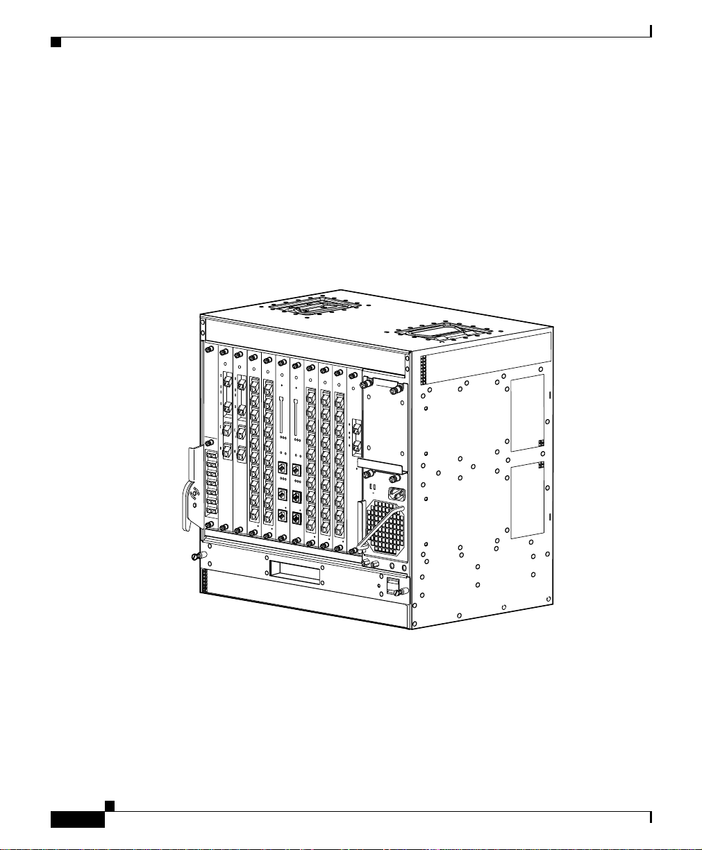
modules, line cards, and 2.5-G transponder trunk line cards. Slot 0 holds two half
height optical OADM modules. Slots 1 through 4 and slots 7 through 10 hold the
line cards and transponder cards. Slots 5 and 6 hold the CPU switch modules.
Power supplies are located on the right side of the chassis next to slot 10. Air inlet
and fan tray assembly are located beneath the slots. Cable management is located
beneath the slots. The system has an electrical backplane for system control. All
optical connections are located on the front of the cards. Figure 1-1 shows a fully
populated chassis.
Figure 1-1 Cisco ONS 15530 Shelf
STATUS
STATUS
STATUS
STATUS
STATUS
STATUS
0
1
2
3
4
5
CON
6
7
CON
8
AUX
9
15530-LCMB-0200
STATUS
STATUS
STATUS
0
T
X
R
X
1
T
X
R
X
2
T
X
R
X
3
T
X
R
X
4
T
X
R
X
T
5
X
R
X
T
X
6
R
X
T
X
7
R
X
T
X
8
R
X
T
X
R
9
X
15530-LCMB-0200
0
T
X
R
X
1
T
X
R
X
2
T
X
R
X
3
T
X
R
X
4
T
X
R
X
T
5
X
R
X
T
X
6
R
X
T
X
7
R
X
T
X
8
R
X
T
X
R
9
X
15530-LCMB-0200
0
1
E
A
S
T
2
T
X
R
X
W
E
3
S
T
4
5
6
7
8
9
15530-LCMB-0200
STATUS
T
X
R
X
T
X
R
X
FASTENERS MUST BE
FULLY ENGAGED PRIOR TO
OPERATING THE POWER SUPPLY
FAIL
GOOD
100-240V
8.0-3.5A
50-60HZ
RESET
RESET
ACTIVE
ACTIVE
T
X
R
X
COMPACT
FLASH
COMPACT
T
FLASH
X
R
X
T
X
R
X
T
A
X
CIRTICAL
MAJOR
L
A
R
MINOR
A
CIRTICAL
MAJOR
X
L
R
A
M
R
S
M
CUTOFF
S
T
X
CUTOFF
R
HIST
X
CUTOFF
CLR
HIST
CLR
T
X
R
X
T
100MBPS
LINK
X
FDX
LINK
R
100MBPS
FDX
X
T
X
CON
R
X
T
X
R
X
AUX
T
X
R
15530-CPU
X
15530-CPU
E
A
E
S
A
T
T
S
X
T
T
X
R
T
T
0
X
X
X
R
T
T
R
X
X
R
X
X
X
W
E
S
T
T
X
R
X
R
X
R
X
T
1
X
W
T
R
X
X
E
R
T
X
S
X
T
T
X
R
T
X
X
2
R
T
R
X
X
X
R
X
T
X
3
T
T
R
X
T
X
X
R
X
X
T
X
T
X
4
T
R
X
X
R
X
R
X
R
T
X
X
R
T
5
R
X
X
X
R
X
T
X
T
R
X
6
X
R
X
T
X
T
R
X
7
X
R
X
T
X
T
R
X
X
8
R
X
T
X
T
R
X
X
9
R
X
15530-LCMB-0200
1-2
The chassis configurations differ in how cooling air is routed through the chassis
and where the lifting handles are placed.
Cisco ONS 15530 Hardware Installation Guide
FAN
STATUS
77670
78-14228-02
Page 3
Chapter 1 Cisco ONS 15530 Overview
7 August 2003
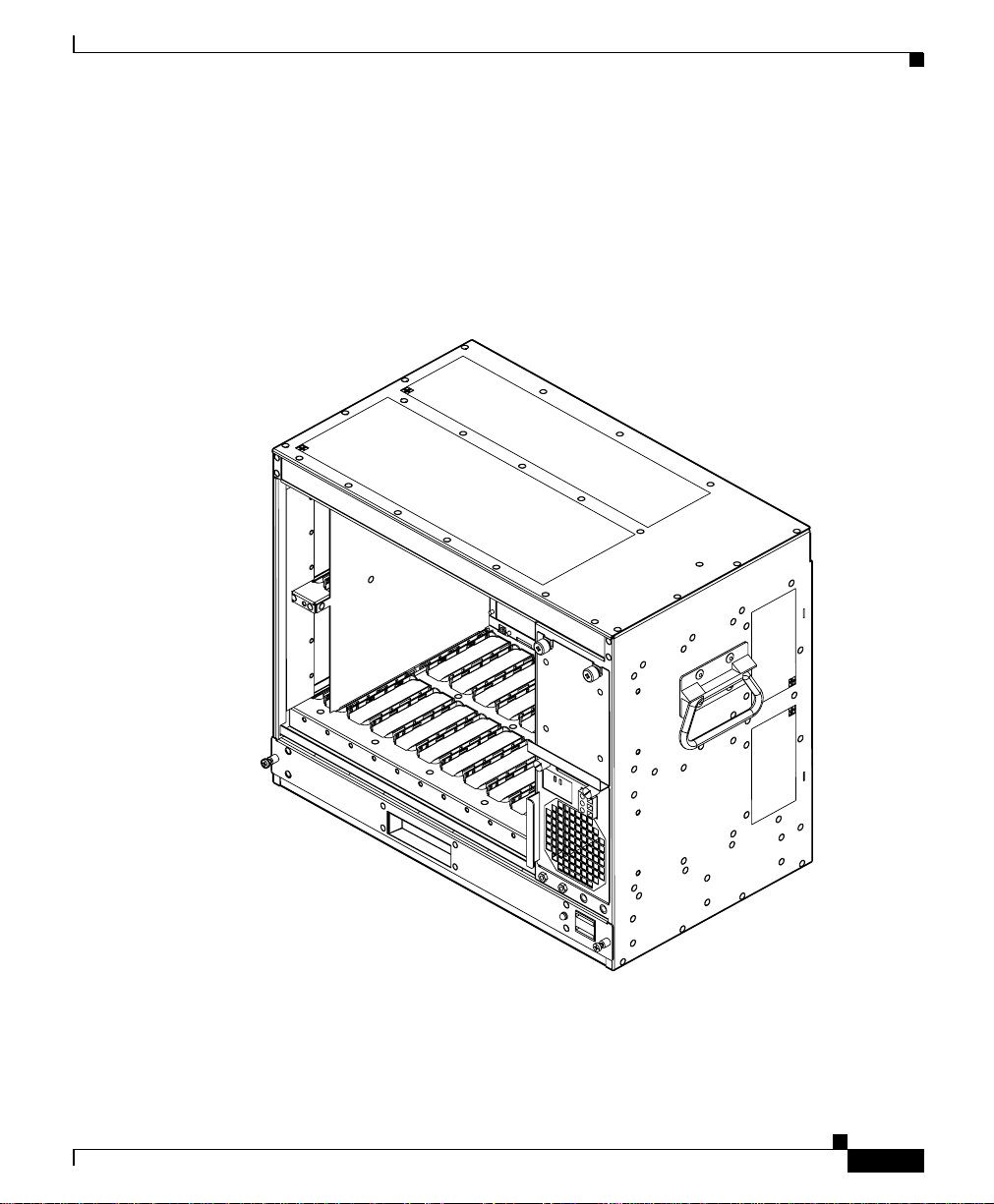
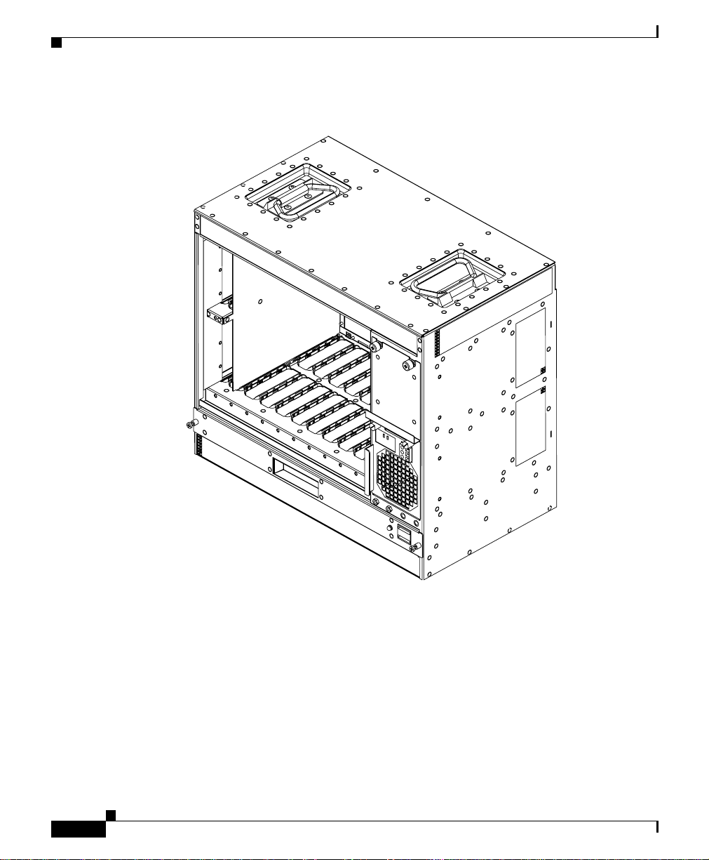
Cisco ONS 15530-CHAS-E Chassis
The dimensions of the Cisco ONS 15530 CHAS-E chassis are 14.4 x 17.3 x 10.1
inches (H x W x D) See Figure 1-2. Handles for lifting the chassis are located on
the sides.
Figure 1-2 Cisco ONS 15530 CHAS-E Chassis
Cisco ONS 15530 Chassis
78-14228-02
FAN
STATUS
77080
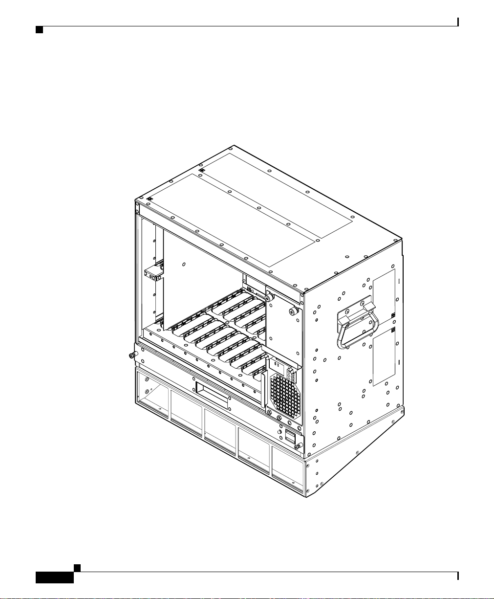
The fan assembly draws in cooling air through the air ramp baffle (see Figure 1-3)
on the bottom of the chassis, pushing the air across the internal components and
out the exhaust baffles on the top of the chassis.
Cisco ONS 15530 Hardware Installation Guide
1-3
Page 4
Cisco ONS 15530 Chassis
Chapter 1 Cisco ONS 15530 Overview
7 August 2003
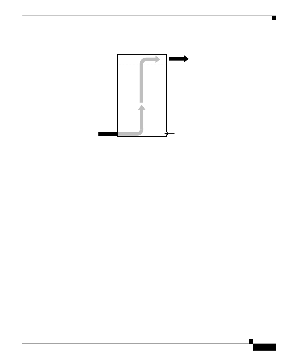
The air ramp baffle for the Cisco ONS 15530 CHAS-E chassis redirects the
cooling air intake as shown in Figure 1-4. The air ramp baffle must be installed
when installing the Cisco ONS 15530 CHAS-E type chassis.
Figure 1-3 Cisco ONS 15530 CHAS-E (with Air Ramp Baffle)
1-4
Cisco ONS 15530 Hardware Installation Guide
FAN
STATUS
77825
78-14228-02
Page 5
Chapter 1 Cisco ONS 15530 Overview
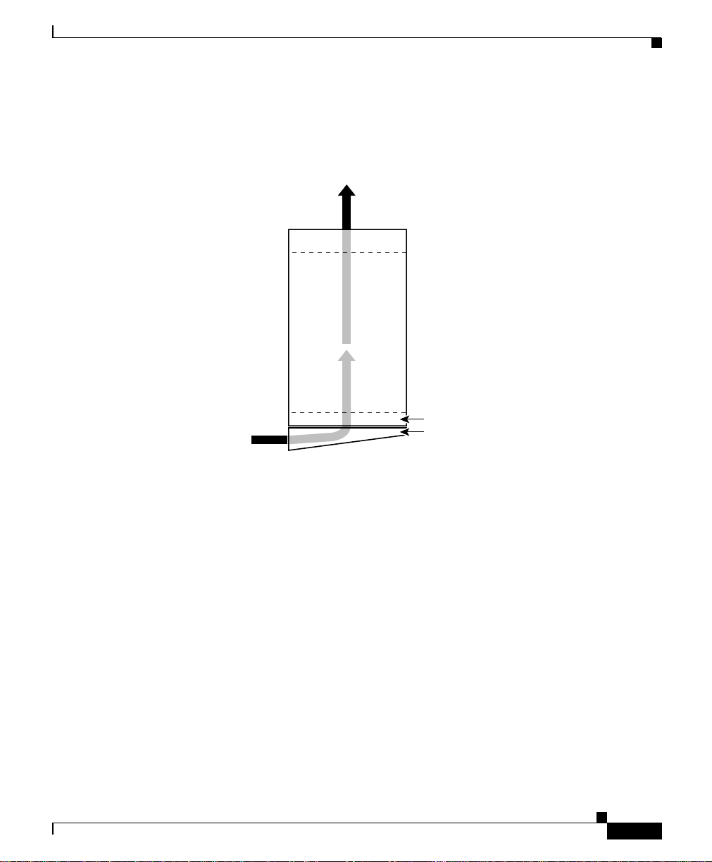
Figure 1-4 Cisco ONS 15530 CHAS-E Chassis Airflow (with Air Ramp Baffle
Cisco ONS 15530 Chassis
7 August 2003
Installed)
Exhaust
air
Top
Front
Ambient air
intake
Bottom
Cisco ONS 15530 CHAS-N Chassis
The dimensions of the Cisco ONS 15530 CHAS-N chassis are 14.4 x 15.7 x 10.1
inches (HxWxD).(See Figure 1-5.) Handles for lifting the chassis are located
on the top. The fan assembly draws in cooling air through the intake baffleson the
front of the chassis, below the fan assembly, pushing the air over the internal
components and out the exhaust on the top rear and sides of the chassis (see
Figure 1-6).
Rear
Fan assembly
Air ramp baffle
77824
78-14228-02
Cisco ONS 15530 Hardware Installation Guide
1-5
Page 6
Cisco ONS 15530 Chassis
Chapter 1 Cisco ONS 15530 Overview
7 August 2003
Figure 1-5 Cisco ONS 15530 CHAS-N Chassis
1-6
Cisco ONS 15530 Hardware Installation Guide
FAN
STATUS
77081
78-14228-02
Page 7
Chapter 1 Cisco ONS 15530 Overview
A
Figure 1-6 Cisco ONS 15530 CHAS-N Chassis Airflow
Cisco ONS 15530 Chassis
7 August 2003
Top
Exhaust
air
Fan Assembly
Front
mbient air
intake
Bottom
Rear
Fan assembly
77668
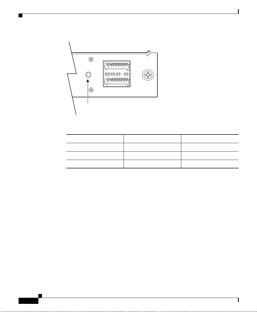
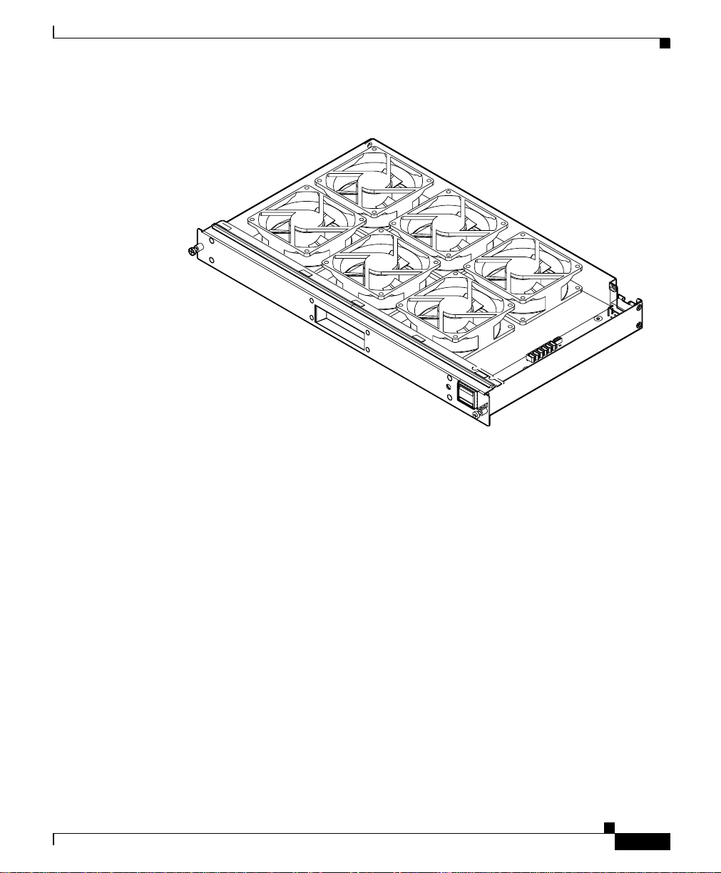
The Cisco ONS 15530 fan assembly is located at the bottom of the chassis. The
assembly contains six individual fans and a fan controller board (see Figure 1-8).
The controller board monitors the status of each fan and reports the status to the
CPU switch modules. If a single fan fails, a minor alarm is reported to the CPU
and the fan assembly LED changes from green to yellow (see Figure 1-7). If two
or more fans fail, a major alarm is reported to the CPU and the fan LED changes
to red.
Table 1-1 lists the fan assembly LED status describing the alarm reports for the
fan assembly. The fan assembly is hot-swappable.
78-14228-02
Cisco ONS 15530 Hardware Installation Guide
1-7
Page 8
Cisco ONS 15530 Chassis
Chapter 1 Cisco ONS 15530 Overview
7 August 2003
Figure 1-7 Fan Assembly LED
77796
Fan assembly
LED
Table 1-1 Fan Assembly Status
Fan Failure LED Status
None Green Normal
One Yellow Minor
Two or more Red Major
1-8
Cisco ONS 15530 Hardware Installation Guide
78-14228-02
Page 9
Chapter 1 Cisco ONS 15530 Overview
Figure 1-8 Fan Assembly
7 August 2003
FAN
Cisco ONS 15530 Chassis
STATUS
77834
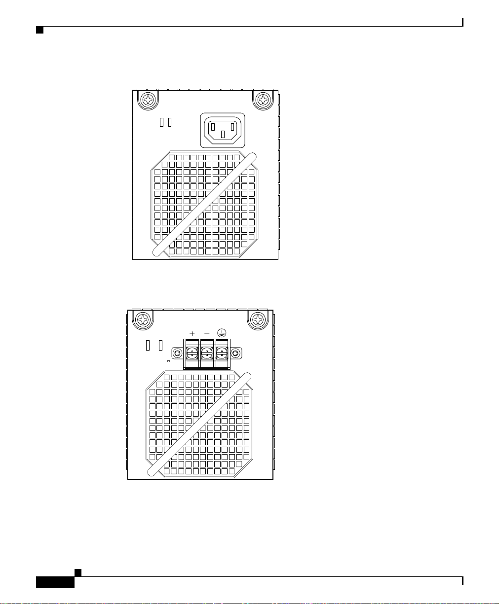
Power Supplies
The Cisco ONS 15530 chassis supports redundant 120–240 VAC (see Figure 1-9)
or –48 VDC (see Figure 1-10) power. The power supplies are located at the right
of the chassis, next to the card slots (see Figure 1-1). Up to two power supplies
can be installed for redundancy.
78-14228-02
Cisco ONS 15530 Hardware Installation Guide
1-9
Page 10
Cisco ONS 15530 Chassis
7 August 2003
Figure 1-9 120–240 VAC Power Supply
FASTENERS MUST BE
FULLY ENGAGED PRIOR TO
OPERATING THE POWER SUPPLY
GOODFAIL
100-240V ~
8.0- 3.5A
50-60 HZ
77894
Figure 1-10 –48 VDC Power Supply
Chapter 1 Cisco ONS 15530 Overview
1-10
FASTENERS MUST BE
FULLY ENGAGED PRIOR TO
OPERATING THE POWER SUPPLY
GOOD
FAIL
-48 TO -60V
17/A
See the “Powering Up the Shelf” section on page 2-47 for more information about
the power supplies.
Cisco ONS 15530 Hardware Installation Guide
77893
78-14228-02
Page 11

Chapter 1 Cisco ONS 15530 Overview
7 August 2003
Backplane
The Cisco ONS 15530 backplane implements all board-to-board signal
interconnects and provides power distribution within the chassis. Connections are
present for two power supplies and the fan assembly. The backplane contains a
total of 12 slots; two half-height slots for the OADM modules, two full height
slots for the CPU switch modules, and eight full height slots for line cards and
transponder cards.
Cable Storage Drawer
The cable storage drawer is mounted directly below the fan assembly. It provides
storage for the excess cable length. Sliding radius limiters move to release the
excess fiber cable slack when the drawer is pulled out, allowing the user to raise
the fiber routing tray and access the fan assembly.
Cisco ONS 15530 Components
Cisco ONS 15530 Components
78-14228-02
The following hardware components can be installed in the Cisco ONS 15530:
• CPU Switch Modules, page 1-12
• OSC Modules and Carrier Motherboards, page 1-17
• PSM, page 1-18
• Transponder Line Cards, page 1-20
• Optical Add Drop Multiplexing Modules, page 1-25
• Wide-Band Variable Optical Attenuator and Per-Band Optical Equalizer
Modules, page 1-26
• ESCON Aggregation Cards, page 1-31
• 8-Port FC/GE Aggregation Cards, page 1-33
• 2.5-Gbps ITU Trunk Cards, page 1-36
• 10-Gbps ITU Trunk Cards, page 1-40
• 10-Gbps Uplink Cards, page 1-44
Cisco ONS 15530 Hardware Installation Guide
1-11
Page 12

Cisco ONS 15530 Components
CPU Switch Modules
The Cisco ONS 15530 supports two CPU switch modules for redundancy, one in
activemode and the other in hot-standby mode. CPU switch modules are installed
in slot 5 and slot 6. Each CPU switch module has a processor, a switch fabric, a
clock, an Ethernet switch for communication between processors and with the
LRC (line card redundancy controller) on the OADM modules and line cards, and
an SRC (switch card redundancy controller). The active processor controls the
system. All LRCs in the system use the system clock and synchronization signals
from the activeprocessor.Interfaceson the CPU switch modules permit access by
10/100 Ethernet, console terminal, or modem connections.
Figure 1-11 shows the front panel of the CPU switch module.
Chapter 1 Cisco ONS 15530 Overview
7 August 2003
1-12
Cisco ONS 15530 Hardware Installation Guide
78-14228-02
Page 13
Chapter 1 Cisco ONS 15530 Overview
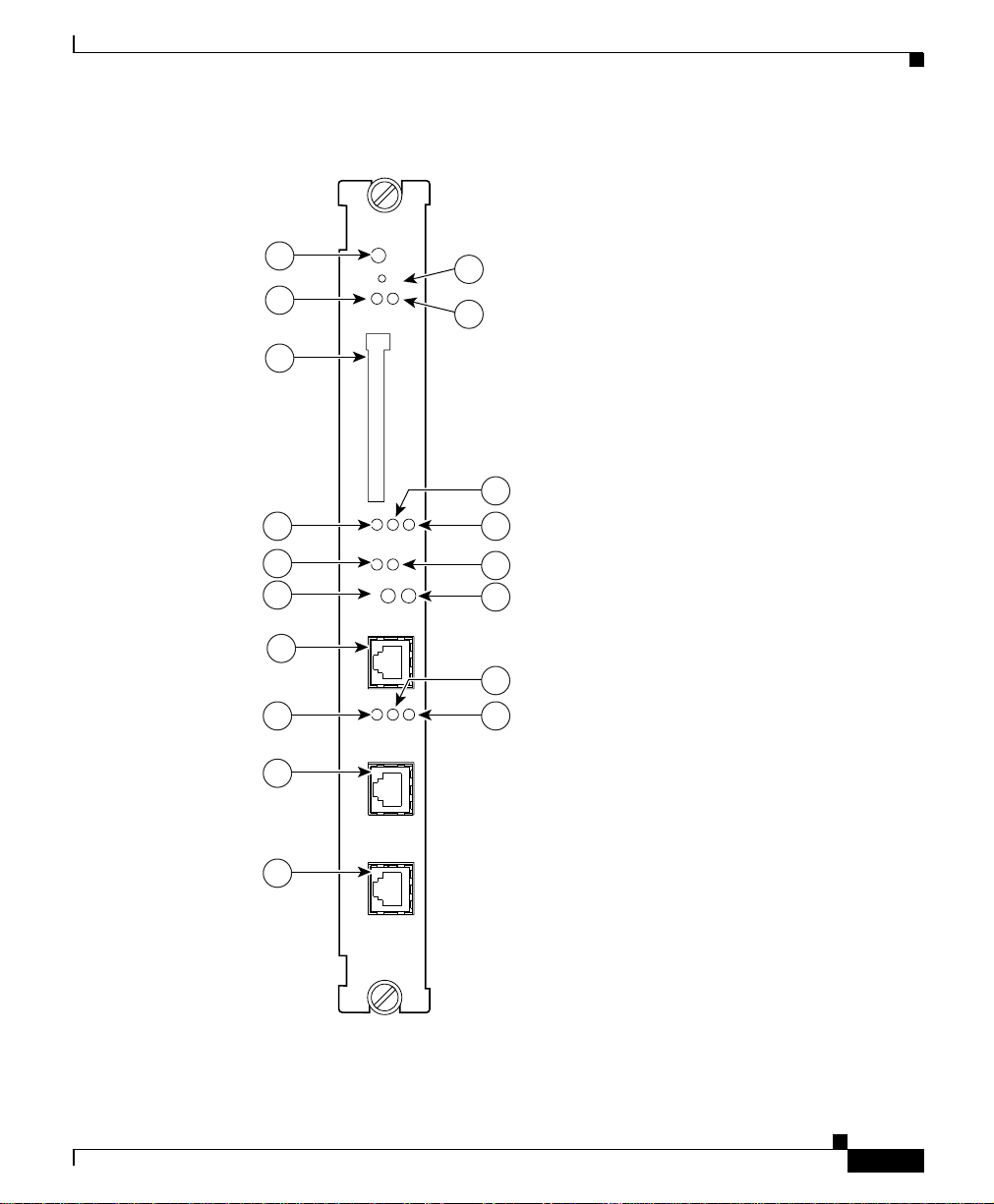
Figure 1-11 Cisco ONS 15530 CPU Switch Module
1
3
7 August 2003
STATUS
RESET
ACTIVE
STANDBY
2
4
Cisco ONS 15530 Components
11
13
14
17
18
5
COMPACT
FLASH
7
6
9
CIRTICAL
A
MINOR
MAJOR
L
A
R
CUTOFF
M
HIST
S
CUTOFF
HIST
CLR
NME
8
10
12
15
100MBPS
FDX
LINK
CON
AUX
15530-CPU
16
78-14228-02
77664
Cisco ONS 15530 Hardware Installation Guide
1-13
Page 14

Cisco ONS 15530 Components
7 August 2003
Callout Description Callout Description
1 Card status LED 10 HIST LED
2 Reset button 11 Cutoff LED
3 Standby LED 12 HIST CLR LED
4 Active LED 13 NME port
5 CompactFlash card slot 14 Link LED
6 Minor alarm LED 15 100 Mbps LED
7 Major alarm LED 16 Full-duplex LED
8 Critical alarm LED 17 Console port
9 Cutoff LED 18 Auxiliary port
CPU Switch Module Ports, LEDs, and Switches
Table 1-2 lists the LEDs on the CPU switch module faceplate with a description
of the status indication.
Chapter 1 Cisco ONS 15530 Overview
1-14
Table 1-2 CPU Switch Module LEDs
LED Status Description
STATUS Green IOS is loaded and running.
Yellow Card is in the process of booting.
ACTIVE Green Module is the primary CPU switch
module, otherwise the LED is off.
STANDBY Green Module is in standby mode, otherwise the
LED is off.
ALARM LEDs
CRITICAL Red A system wide critical alarm exists.
MAJOR Yellow A system wide major alarm exists.
MINOR Yellow A system wide minor alarm exists.
HIST Yellow A system wide major or minor alarm has
occurred.
Cisco ONS 15530 Hardware Installation Guide
78-14228-02
Page 15

Chapter 1 Cisco ONS 15530 Overview
Table 1-2 CPU Switch Module LEDs (continued)
LED Status Description
HIST CLR Yellow A system wide major or minor alarm has
CUTOFF Red A major or minor alarm exists and the
FDX Green Module is running full-duplex.
100MBPS Green Module is running at 100 Mbps.
LINK Green Link is up.
Cisco ONS 15530 Components
7 August 2003
occurred.
cutoff button has been pushed.
Off Module is running half-duplex.
Off Module is running at 10 Mbps.
Off Link is down.
78-14228-02
Cisco ONS 15530 Hardware Installation Guide
1-15
Page 16

Chapter 1 Cisco ONS 15530 Overview
Cisco ONS 15530 Components
7 August 2003
Connector Ports
The front panel on the CPU switch module contains three ports with RJ-45
connectors (see Figure 1-11):
• NetworkManagement Ethernet port (NME)—This Ethernet port connects the
CPU switch module to a 10/100BASE-T network management LAN.
• Console port (CON)—This asynchronous EIA/TIA-232 serial port connects
a terminal to the CPU switch module for local administrative access.
• Auxiliary port (AUX)—This asynchronous EIA/TIA-232 serial port connects
a modem to the CPU switch module for remote administrative access.
The RJ-45 connectors on the front panel of the CPU switch module have an extra
EMI shield and the signals going to them are filtered. Table 1-3 shows the pinouts
of the console and auxiliary ports.
Table 1-3 Console and Auxiliary Port RJ-45 Pinout
Pin
# Console Auxiliary
Direction Function Direction Function
1 Output RTS Request To Send Output RTS Request To Send
2 Output DTR Data terminal ready Output DTR Data terminal ready
3 Output TxD Transmit data Output TxD Transmit data
4 N/A GND Ground N/A GND Ground
5 N/A GND Ground N/A GND Ground
6 Input RxD Receive data Input RxD Receive data
7 Input DSR Data set ready Input CD Carrier Detect
8 Input CTS Clear To Send Input CTS Clear To Send
CompactFlash Card Slot
A CompactFlash card slot (see Figure 1-11) can store the Cisco IOS image or a
system configuration file on a CompactFlash memory card. The system can also
boot from the software stored on the CompactFlash memory card.
Cisco ONS 15530 Hardware Installation Guide
1-16
78-14228-02
Page 17

Chapter 1 Cisco ONS 15530 Overview
7 August 2003
OSC Modules and Carrier Motherboards
The OSC (optical supervisory channel) module supports an optional out-of-band
management channel for communicating between systems on the network. Using
a 33rd wavelength(channel 0), the OSC allows control and management trafficto
be carried without requiring a separate Ethernet connection to each Cisco ONS
15530 in the network. Up to two OSC modules can be installed in the carrier
motherboard, one module for the west direction and one for the east direction.
The OSC always terminates on a neighboring node. By contrast, data channels
may or may not be terminated on a givennode,depending on whether the channels
on the OADM modules are treated as either express (pass-through) or add/drop
channels.
Figure 1-12 shows the front panel of the OSC module.
Figure 1-12 OSC Module
STATUS
1
Cisco ONS 15530 Components
78-14228-02
T
X
R
X
TX
RX
3
15530-OSCM
2
4
5
77667
Callout Description Callout Description
1 Card status LED 4 Transmit LED
2 OADM port 5 Card handle
3 Receive LED
Cisco ONS 15530 Hardware Installation Guide
1-17
Page 18

Cisco ONS 15530 Components
OSC Module LEDs
PSM
Chapter 1 Cisco ONS 15530 Overview
7 August 2003
Table 1-4 lists the LEDs on the OSC module faceplate, their default conditions,
and what the conditions indicate.
Table 1-4 OSC Module LEDs
LED Status Description
STATUS Green OSC module initialization process is complete.
Yellow OSC module is in initialization process.
TX Green Transmit laser is enabled.
RX Green Light reception exists at wave OSC interface.
The PSM (protection switch module) provides trunk fiber protection for Cisco
ONS 15530 systems configured in point-to-point topologies. The PSM sends the
DWDM signal from the OADM module to both the west and east directions. It
receives both the west and east signals and selects one to send to the OADM
module. When a trunk fiber cut occurs on the active path, the PSM switches the
received signal to the standby path. Since the PSM occupies one of the OADM
subslots in the shelf, it protects a maximum of four channels and the OSC in a
single shelf configuration.
The PSM also has an optical monitor port for testing the west and east receive
signals. This port samples one percent of these signals which can be monitored
with an optical power meter, or optical spectrum analyzer.
A PSM can be installed in subslots 0/0 and 0/1 of the Cisco ONS 15530 chassis.
The PSM for the Cisco ONS 15530 has a front panel with four MU connector
pairs, as shown in Figure 1-13.
1-18
Cisco ONS 15530 Hardware Installation Guide
78-14228-02
Page 19

Chapter 1 Cisco ONS 15530 Overview
Figure 1-13 PSM
Cisco ONS 15530 Components
7 August 2003
1
2
3
4
5
78-14228-02
85519
1 Rx/Tx West ports
2 Rx/Tx East ports
3 East/West LEDs
4 East/West Optical Monitor
ports
5 Common In/Out ports
Cisco ONS 15530 Hardware Installation Guide
1-19
Page 20

Cisco ONS 15530 Components
PSM LEDs
Table 1-5 lists the LEDs on the PSM faceplate, their default conditions, and what
the conditions indicate.
Table 1-5 PSM LEDs
LED
Status Description
Green Software initialization is
successful.
Off Board failure.
Transponder Line Cards
The protocol-transparent and bit-rate transparent transponder line card converts a
single client signal into an ITU wavelength, or channel. The transponder line
cards have tunable lasers and you can configure the line cards to work in two
different wavelengths. The Cisco ONS 15530 holds up to four transponder line
cards, one for each wavelength supported by the OADM modules.
The Cisco ONS 15530 supports four types of single client interface transponder
line cards: SM (single mode) unprotected, SM splitter protected,
MM (multimode) unprotected, and MM splitter protected. Both types of
SM transponder line cards accept SM client signals on the 1310-nm wavelength
through an SC connector and support client signal clock rates ranging from
16 Mbps to 2.5 Gbps. Both types of MM transponder line cards accept SM and
MM client signals on the 1310-nm wavelength through an SC connector and
support client signal clock rates ranging from 16 Mbps to 622 Mbps (see
Figure 1-14 and Figure 1-15).
Chapter 1 Cisco ONS 15530 Overview
7 August 2003
1-20
Cisco ONS 15530 Hardware Installation Guide
78-14228-02
Page 21

Chapter 1 Cisco ONS 15530 Overview
Figure 1-14 Transponder Line Card LEDs (Nonsplitter)
1
3
4
5
7 August 2003
STATUS
T
X
R
T
X
X
R
X
T
X
T
X
2
6
Cisco ONS 15530 Components
78-14228-02
7
R
X
R
X
8
77659
Cisco ONS 15530 Hardware Installation Guide
1-21
Page 22

Cisco ONS 15530 Components
Callout Description Callout Description
Chapter 1 Cisco ONS 15530 Overview
7 August 2003
1 Card status LED 5 Client side transmit LED
2 ITU side port 6 Client side transmit port
3 ITU transmit LED 7 Client side receive LED
4 ITU receive LED 8 Client side receive port
1-22
Cisco ONS 15530 Hardware Installation Guide
78-14228-02
Page 23

Chapter 1 Cisco ONS 15530 Overview
Figure 1-15 Transponder Line Card LEDs (Splitter)
1
Cisco ONS 15530 Components
7 August 2003
STATUS
10
2
4
5
6
8
W
E
S
T
T
X
R
X
E
A
S
T
T
X
R
X
W ITU TX
W ITU RX
E ITU TX
E ITU RX
1310 TX
1310 RX
T
X
R
X
T
X
R
X
T
X
R
X
3
7
9
11
78-14228-02
77660
Cisco ONS 15530 Hardware Installation Guide
1-23
Page 24

Cisco ONS 15530 Components
Callout Description Callout Description
The transponder line cards are hot swappable, permitting in-service upgrades and
replacement. All client signals on the transponders are supported in 3R (reshape,
retime, retransmit) mode, regardless of protocol encapsulation type. The client
interfaces also support the OFC (open fiber control) safety protocol for Fibre
Channel, ISC compatibility mode, and FICON. The client side ports use SC-type
connectors.
On the trunk side, the transponder line card output laser power ranges from
5 to 10 dBm and the receive detector has a sensitivity of –32 dBm. The ports on
the trunk side use MU-type connectors.
Chapter 1 Cisco ONS 15530 Overview
7 August 2003
1 Card status LED 7 East side ITU port
2 West side ITU LED 8 Client side transmit LED
3 West side ITU port 9 Client side transmit port
4 ITU side transmit LED 10 Client side receive LED
5 ITU side receive LED 11 Client side receive port
6 East side ITU LED
Transponder Line Card LEDs
Table 1-6 lists the LEDs on the transponder line card faceplate, their default
conditions, and what the conditions indicate.
Table 1-6 Transponder Line Card LEDs
LED Status Description
STATUS Green Card is properly initialized.
1
EAST
TX (Trunk port) Green Port is up and transmit laser is enabled.
Cisco ONS 15530 Hardware Installation Guide
1-24
Blinking green Good system clock is present and card is
out of reset state.
Yellow System clock is not present.
Green Card is listening to the east side signal.
78-14228-02
Page 25

Chapter 1 Cisco ONS 15530 Overview
7 August 2003
Table 1-6 Transponder Line Card LEDs (continued)
LED Status Description
RX (Trunk port) Green Light reception exists at the port.
1
WEST
Green Card is listening to the west side signal.
TX (Client port) Green Port is up and transmit laser is enabled.
RX (Client port) Green Light reception exists at the port.
1. This LED is only present on transponder line cards with splitter.
Optical Add Drop Multiplexing Modules
The OADM modules are passive devices that optically multiplex and demultiplex
a specific band of four ITU wavelengths. The OADM modules supported by the
Cisco ONS 15530 each add and drop a specified band of four channels at a node
and pass the other bands through. To support the 32-channel spectrum, there are
eight different 4-channel cards (see Figure 1-16).
In the transmit direction, the OADM modules multiplex signals transmitted by the
transponder line cards and 10G ITU trunk cards over optical cross connections
and provide the interfaces to connect the multiplexed signal to the DWDM trunk
side. In the receive direction, the OADM modules demultiplex the signals from
the trunk side before passing them over optical cross connections to the
transponder line cards and 10G ITU trunk cards.
Cisco ONS 15530 Components
78-14228-02
Cisco ONS 15530 Hardware Installation Guide
1-25
Page 26

Cisco ONS 15530 Components
Figure 1-16 OADM Module
Chapter 1 Cisco ONS 15530 Overview
7 August 2003
1
91400
Wide-Band Variable Optical Attenuator and Per-Band Optical Equalizer Modules
The WB-VOA (wide-band variable optical attenuator) and PB-OE (per-band
power equalizer) modules are half-width modules that allow the ONS 15530 to
extend the internodal and ring circumference distances and number of nodes
supported for point-to-point, hub ring, and mesh ring networks by equalizing
power levels.
Cisco ONS 15530 Hardware Installation Guide
1-26
78-14228-02
Page 27

Chapter 1 Cisco ONS 15530 Overview
The WB-VOA module and the PB-OE module are available in single and dual
band versions. These modules are installed into a carrier motherboard. This
motherboard is installed into and operates on the Cisco ONS 15530 chassis. The
carriermotherboard can be installed in slots 1 to 4 or 7 to 10. All optical connectors
are located on the front panel and the connectors are angled.
Figure 1-17 and Figure 1-18 show the single and dual versions of the WB-VOA
module. Figure 1-19 and Figure 1-20 show the single-band and dual-band
versions of the PB-OE module.
Figure 1-17 Single WB-VOA Module
1
7 August 2003
15500-VOA-0100
PM1
STA
2
Cisco ONS 15530 Components
IN OUT
3
4
5
79166
Callout Description Callout Description
1 PM1 LED 4 OUT port
2 Card status LED 5 Handle
3 IN port
78-14228-02
Cisco ONS 15530 Hardware Installation Guide
1-27
Page 28

Cisco ONS 15530 Components
Table 1-7 Single WB-VOA Module LEDs
LED Status Description
PM1 Green Light reception exists at the port.
STA Green Card is properly initialized.
Figure 1-18 Dual WB-VOA Module
1
7 August 2003
2
15500-VOA-0200
PM2
PM1
STA
3
Chapter 1 Cisco ONS 15530 Overview
IN1 OUT1 IN2 OUT2
4
5
6
7
8
79168
Callout Description Callout Description
1 PM2 LED 5 OUT1 port
2 PM1 LED 6 Handle
3 Card status LED 7 IN2 port
4 IN1 port 8 OUT2 port
1-28
Cisco ONS 15530 Hardware Installation Guide
78-14228-02
Page 29

Chapter 1 Cisco ONS 15530 Overview
Table 1-8 Dual WB-VOA Module LEDs
LED Status Description
PM2 Green Light reception exists at the port.
PM1 Green Light reception exists at the port.
STATUS Green Card is properly initialized.
Figure 1-19 Single-Band PB-OE Module
Cisco ONS 15530 Components
7 August 2003
1
2
3
4
5
6
7
79173
Callout Description Callout Description
1 PM1 LED 5 OUT port
2 Card status LED 6 UPG IN port
3 IN port 7 UPG OUT port
4 Handle
78-14228-02
Cisco ONS 15530 Hardware Installation Guide
1-29
Page 30

Cisco ONS 15530 Components
Table 1-9 Single-Band PB-OE Module
LED Status Description
PM1 Green Light reception exists at the port.
STA Green Card is properly initialized.
Figure 1-20 Dual-Band PB-OE Module
1
7 August 2003
2
15500-PEQ-02EF
PM2 PM1 STA
IN OUT UPG IN UPG OUT
3
4
Chapter 1 Cisco ONS 15530 Overview
5
6
7
8
79006
Callout Description Callout Description
1 PM2 LED 5 Handle
2 PM1 LED 6 OUT port
3 Card status LED 7 UPG IN port
4 IN port 8 UPG OUT port
1-30
Cisco ONS 15530 Hardware Installation Guide
78-14228-02
Page 31

Chapter 1 Cisco ONS 15530 Overview
7 August 2003
Table 1-10 Dual-Band PB-OE LEDs
LED Status Description
PM2 Green Light reception exists at the port.
PM1 Green Light reception exists at the port.
STATUS Green Card is properly initialized.
ESCON Aggregation Cards
The ESCON aggregation card is a 10-port card for ESCON (Enterprise Systems
Connection) traffic. The ESCON card converts the 10 client signals from optical
to electrical and then aggregates them into a single 2.5-Gbps signal. This
aggregated signal is sent through the backplane and the active switch fabric to
either a 10G ITU trunk card or a 10-Gbps uplink card. The cross connection
between the two cards is configured using the CLI (command-line interface). The
ESCON aggregation card has a redundant backplane connection.
The ESCON aggregation card uses multi-mode 62.5/125 um optical cable with
SFPs (small form factor pluggables) and MT-RJ connectors for the client signals.
(See Figure 1-21.)
Cisco ONS 15530 Components
78-14228-02
Note The SFPs (part number 15500-XVRA-01A2 ONS 15530 ESCON-1310nm
MM-MTRJ) must be purchased separately.
Note A patch cable to adapt MT-RJ connectors to standard ESCON connectors directly
or intermediately to SC-type connectors may be required.
This signal is sent through the switch fabric to a 10G ITU trunk card or a 10-Gbps
uplink card. The 10Gbps ITU trunk card converts the aggregated signal to an
ITU-compliant wavelength, or channel. The 10-Gbps uplink card converts the
aggregated signal to transmit to another shelf.
Cisco ONS 15530 Hardware Installation Guide
1-31
Page 32

Cisco ONS 15530 Components
Figure 1-21 Cisco ONS 15530 ESCON Aggregation Card
1
7 August 2003
STATUS
T
X
R
X
T
X
R
X
0
1
2
3
T
X
R
X
Chapter 1 Cisco ONS 15530 Overview
0
4
T
X
R
X
T
X
R
X
T
X
R
X
T
X
R
X
T
X
R
X
T
X
R
X
T
X
R
X
T
X
R
X
2
3
4
5
6
7
8
9
15530-LCMB-0200
77663
1-32
Cisco ONS 15530 Hardware Installation Guide
78-14228-02
Page 33

Chapter 1 Cisco ONS 15530 Overview
Callout Description Callout Description
1 Card status LED 3 Port receive LED
2 Port transmit LED 4 Port number
Table 1-11 describes the ESCON aggregation card LED status.
Table 1-11 ESCON Aggregation Card LEDs
LED Status Description
STATUS Green Card is properly initialized.
TX Green Port is up and transmit laser is enabled.
RX Green Light reception exists at the port.
Cisco ONS 15530 Components
7 August 2003
Blinking green Good system clock is present and card is out of
reset state.
Yellow System clock is not present.
8-Port FC/GE Aggregation Cards
The Cisco ONS 15530 supports a line card specifically for FC (Fibre Channel)
and GE (Gigabit Ethernet) traffic. The 8-port Fibre Channel/Gigabit Ethernet
aggregation card accepts up to eight SFP (small form-factor pluggable) optics for
client traffic. Each SFP optic supports either FC or GE, depending on how it is
configuredin the CLI. The 8-port FC/GE aggregation card converts client signals
from two adjacent port pairs (0–1, 2–3, 4–5, or 6–7) from optical form to
electrical form, and then aggregates them into four 2.5-Gbps signals. These
aggregated signals pass through the backplane and the switch fabric on the active
CPU switch module to a 2.5-Gbps ITU trunk card, a 10-Gbps ITU trunk card, or
a 10-Gbps uplink card. The cross connections between the two cards through the
backplane and switch fabric are configured using the CLI. The 8-port FC/GE
aggregation card has redundant connections over the backplane to the switch
fabric on the active and standby CPU switch modules.
Note The 8-port FC/GE aggregation card also supports FICON trafficc at 1 Gbps.
78-14228-02
Cisco ONS 15530 Hardware Installation Guide
1-33
Page 34

Chapter 1 Cisco ONS 15530 Overview
Cisco ONS 15530 Components
7 August 2003
Note We strongly recommend configuringport pairs as FC only or GE only.Mixing
FC and GE in a port pair increases the FC signal latency between nodes.
The 8-port FC/GE aggregation card uses single-mode and multimode SFP optics
for the client signals. There are no restrictions on populating the line card with
SFPs. For example, you can mix a single-mode SFP optic with a multimode SFP
optic in the same port pair. Table 1-12 lists features for the SFP optics supported
by the 8-port FC/GE aggregation card.
Table 1-12 8-Port FC/GE aggregation card SFP Optics Features
Part Number Supported Protocols Fiber Type Wavelength
15500-XVRA-02C1 Gigabit Ethernet1, Fibre
Channel (1 Gbps)
2
15500-XVRA-03B1 Gigabit Ethernet3, Fibre
Channel (1 Gbps)
1. 1000BaseSX
2. FC-0-100-M5-SN-S and FC-0-100-M6-SN-S standards
3. 1000BaseLX
4. FC-0-100-SM-LC-S standard
4
MM 50/125 m
850 nm Duplex LC
MM 62.5/125 m
SM 9/125 m 1310 nm Duplex LC
Connector
Type
1-34
The Cisco ONS 15530 supports up to four 8-port FC/GE aggregation cards for a
total of 32 client signals.
Cisco ONS 15530 Hardware Installation Guide
78-14228-02
Page 35

Chapter 1 Cisco ONS 15530 Overview
Figure 1-22 8-Port FC/GE Aggregation Card
1
7 August 2003
STATUS
T
X
R
X
T
X
R
X
0
1
2
3
T
X
R
X
Cisco ONS 15530 Components
0
4
T
X
R
X
T
X
R
X
T
X
R
X
T
X
R
X
T
X
R
X
T
X
R
X
2
3
4
5
6
7
15530FCGE-8P
85440
78-14228-02
Cisco ONS 15530 Hardware Installation Guide
1-35
Page 36

Chapter 1 Cisco ONS 15530 Overview
Cisco ONS 15530 Components
7 August 2003
1 Card status LED 2 Transmit Port status
3 Receive Port status 4 Port number
Table 1-13 describes the LEDs on the 8-port FC/GE aggregation card.
Table 1-13 8-Port FC/GE aggregation card LEDs
LED Status Description
STATUS Off No power to the board.
Red Card is in reset or the LRC is not configured.
Yellow Card is out of reset.
Green Card is properly initialized.
TX Green Port is up and transmit laser is enabled.
RX Green Light reception exists at the port.
2.5-Gbps ITU Trunk Cards
The 2.5-Gbps ITU trunk card sends and receives the ITU grid wavelength signal
to and from an OADM module. This card accepts a 2.5-Gbps (3.125-Gbps line
rate) electrical signal from either a 10-port ESCON aggregation card or an 8-port
FC/GE aggregation card, which is converted to the ITU grid wavelength, or
channel. The 2.5-Gbps ITU trunk card has redundant interfaces to the backplane,
connecting to the switch fabrics on the active and standby CPU switch modules.
The ITU laser is tunable to one of two channel frequencies. There are 16 different
2.5-Gbps ITU trunk cards (for channels 1–2, 3–4,..., 31–32) to support the
32 channels.
The 2.5-Gbps ITU trunk card has two versions: nonsplitter (shown in Figure 1-24)
and splitter (shown in Figure 1-23). The nonsplitter version has only one pair of
optical connectors on the front panel, which connects to either the east or the west
OADM module, and can be used for unprotected, line card protected, or switch
fabric protected applications. The card supports 32 channels as shown in
Table A-2 on page A-3.
Cisco ONS 15530 Hardware Installation Guide
1-36
78-14228-02
Page 37
Chapter 1 Cisco ONS 15530 Overview
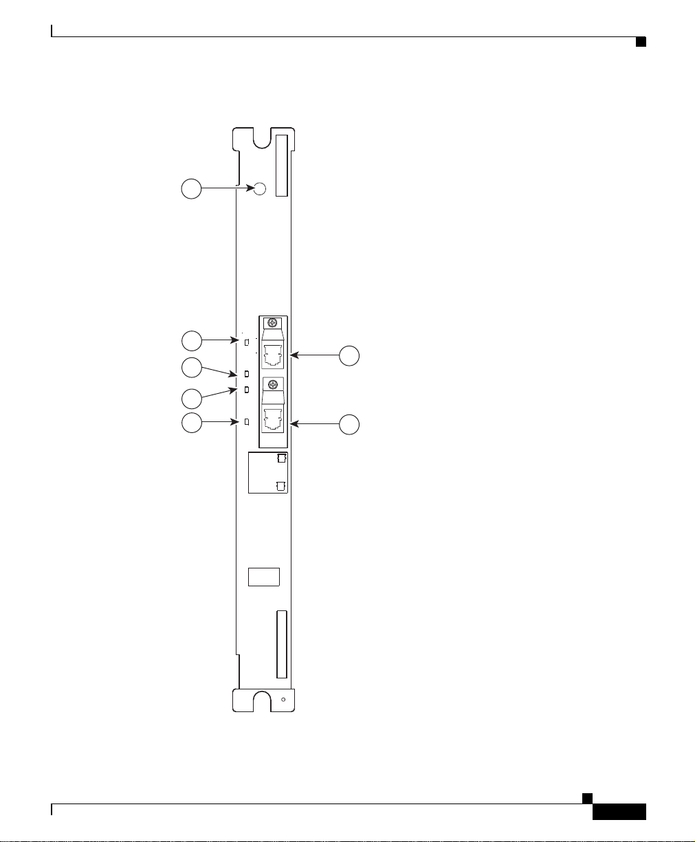
Figure 1-23 2.5-Gbps ITU Trunk Card (Splitter)
7 August 2003
STATUS
W
T
E
X
S
R
T
T
X
R
X
E
A
S
T
X
T
X
R
X
W ITU TX
W ITU RX
E ITU TX
E ITU RX
Cisco ONS 15530 Components
78-14228-02
91504
Cisco ONS 15530 Hardware Installation Guide
1-37
Page 38

Cisco ONS 15530 Components
1 Card status LED 5 Receive LED
2 West side port LED 6 East side port LED
3 West side port 7 East side port
4 Transmit LED
Chapter 1 Cisco ONS 15530 Overview
7 August 2003
1-38
Cisco ONS 15530 Hardware Installation Guide
78-14228-02
Page 39
Chapter 1 Cisco ONS 15530 Overview
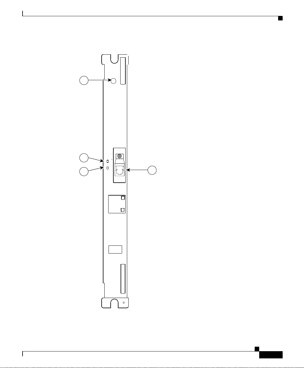
Figure 1-24 2.5-Gbps ITU Trunk Card (Nonsplitter)
1
2
3
7 August 2003
STATUS
T
X
R
T
X
X
R
T
X
X
R
X
4
Cisco ONS 15530 Components
78-14228-02
W ITU TX
W ITU RX
E ITU TX
E ITU RX
85315
Cisco ONS 15530 Hardware Installation Guide
1-39
Page 40

Cisco ONS 15530 Components
7 August 2003
1 Card status LED 2 Transmit LED
3 Receive LED 4 Transmit/Receive port
Table 1-14 lists and describes the 2.5-Gbps ITU Trunk Card LEDs.
Table 1-14 2.5-Gbps ITU Trunk Card LEDs
LED Status Description
STATUS Green Card is properly initialized.
WEST Green Card is listening to the west side signal.
TX Green Port is up and transmit laser is enabled.
RX Green Light reception exists at the port.
EAST Green Card is listening to the east side signal.
10-Gbps ITU Trunk Cards
Chapter 1 Cisco ONS 15530 Overview
1-40
The 10-Gbps ITU trunk card sends and receives the ITU grid wavelength signal
to and from an OADM module. This card accepts up to four 2.5-Gbps
(3.125-Gbps line rate) electrical signals from the 10-port ESCON aggregation
cards and 8-port FC/GE aggregation cards, and combines them into one 10-Gbps
signal, which is converted to the ITU grid wavelength, or channel. The 10-Gbps
ITU trunk card has four separate redundant interfaces to the backplane, each
connecting to the switch fabrics on the active and standby CPU switch modules.
The 10-Gbps ITU trunk card has two versions: nonsplitter and splitter. The
nonsplitter version has only one pair of optical connectors on the front panel,
which connects to either the east or the west OADM module, and can be used for
unprotected, line card protected, or switch fabric protected applications (see
Figure 1-25). The splitter version of the 10-Gbps ITU trunk card has two pairs of
optical connectors on the front panel, which connect to the east and west OADM
modules, and is designed for splitter protected applications (see Figure 1-26).
The Cisco ONS 15530 supports up to four 10-Gbps ITU trunk cards for a total of
four channels.
Cisco ONS 15530 Hardware Installation Guide
78-14228-02
Page 41

Chapter 1 Cisco ONS 15530 Overview
Figure 1-25 10-Gbps ITU Trunk Card (Nonsplitter)
1
3
4
7 August 2003
STATUS
T
X
R
X
T
X
R
X
2
Cisco ONS 15530 Components
78-14228-02
77661
Cisco ONS 15530 Hardware Installation Guide
1-41
Page 42

Cisco ONS 15530 Components
1 Card status LED 3 Transmit LED
2 ITU port 4 Receive LED
Chapter 1 Cisco ONS 15530 Overview
7 August 2003
1-42
Cisco ONS 15530 Hardware Installation Guide
78-14228-02
Page 43

Chapter 1 Cisco ONS 15530 Overview
Figure 1-26 10-Gbps ITU Trunk Card (Splitter)
1
2
4
5
6
7 August 2003
STATUS
W
E
T
S
X
T
R
X
T
X
R
X
E
T
A
X
S
T
R
X
3
7
Cisco ONS 15530 Components
78-14228-02
W ITU TX
W ITU RX
E ITU TX
E ITU RX
77662
Cisco ONS 15530 Hardware Installation Guide
1-43
Page 44

Cisco ONS 15530 Components
1 Card status LED 5 Receive LED
2 West side port LED 6 East side port LED
3 West side port 7 East side port
4 Transmit LED
Table 1-15 describes the10-Gbps ITU trunk card LED status.
Table 1-15 10-Gbps ITU Trunk Card LEDs
LED Status Description
STATUS Green Card is properly initialized.
WEST Green Card is listening to the west side signal.
TX Green Port is up and transmit laser is enabled.
RX Green Light reception exists at the port.
EAST Green Card is listening to the east side signal.
Chapter 1 Cisco ONS 15530 Overview
7 August 2003
10-Gbps Uplink Cards
The 10-Gbps uplink card, shown in Figure 1-27, sends and receives a 10-GE
1310-nm signal to and from a 10-GE uplink card on another Cisco ONS 15530,
or to and from a 10-GE transponder module on a Cisco ONS 15540 ESP or
Cisco ONS 15540 ESPx. This card accepts up to four (3.125-Gbps line rate)
electrical signals from 10-port ESCON aggregation cards and 8-port FC/GE
aggregation cards, and combines them into one 10-GE signal.
The 10-Gbps uplink card has four separate redundant interfaces to the backplane.
Each interface connects to the switch fabric on the activeand standby CPU switch
modules.
The 10-Gbps uplink card has only one version: nonsplitter. The nonsplitter
version has only one pair of optical connectors on the front panel and can be used
for unprotected or line card protected applications. For splitter protected
configurations, the splitter line card motherboards on the Cisco ONS 15540 ESP
and the Cisco ONS 15540 ESPx provide the facility protection.
Cisco ONS 15530 Hardware Installation Guide
1-44
78-14228-02
Page 45

Chapter 1 Cisco ONS 15530 Overview
The Cisco ONS 15530 supports up to four 10-Gbps uplink cards for a total of four
signals.
Cisco ONS 15530 Components
7 August 2003
78-14228-02
Cisco ONS 15530 Hardware Installation Guide
1-45
Page 46

Cisco ONS 15530 Components
Figure 1-27 10-Gbps Uplink Card
1
Chapter 1 Cisco ONS 15530 Overview
7 August 2003
STATUS
3
4
T
X
T
X
R
X
R
X
15530-10GE-UPLINK
2
5
77665
1-46
Cisco ONS 15530 Hardware Installation Guide
78-14228-02
Page 47

Chapter 1 Cisco ONS 15530 Overview
Table 1-16 describes the 10-Gbps uplink line card LED status.
Table 1-16 10-Gbps Uplink Line Card LEDs
LED Status Description
STATUS Green Card is properly initialized.
TX Green Port is up and transmit laser is enabled.
RX Green Light reception exists at the port.
Cisco ONS 15530 Components
7 August 2003
78-14228-02
Cisco ONS 15530 Hardware Installation Guide
1-47
Page 48

Cisco ONS 15530 Components
Chapter 1 Cisco ONS 15530 Overview
7 August 2003
1-48
Cisco ONS 15530 Hardware Installation Guide
78-14228-02
 Loading...