

Page 1

Installing the Cisco ONS 15454 SDH E1-75/120
Impedance Conversion Panel
Product Name: 15454E-E1-75BB=
This document contains a description of E1-75/120 conversion panel (“E1-75 Black Box”) features,
installation procedures, and technical specifications. Use this document in conjunction with the Cisco
ONS 15454 SDH Reference Manual and the Cisco ONS 15454 SDH Procedure Guide when working with
E1-75/120 conversion panels.
This document contains the following sections:
• E1-75/120 Impedance Conversion Panel Description, page 2
• E1-75/120 Impedance Conversion Panel Specifications, page 3
• Install the E1-75/120 Conversion Panel, page 4
• Install Ground and Cables, page 5
• Related Documentation, page 7
• Obtaining Documentation, page 7
• Obtaining Technical Assistance, page 8
• Obtaining Additional Publications and Information, page 10
This document contains the following procedures:
Install the E1-75/120 Conversion Panel, page 4
Install Cables with Molex 96-Pin LFH Connectors on 120-Ohm Side, page 6
Install Cables with 1.0/2.3 Miniature Coax Connectors on 75-Ohm Side, page 6
Replace Cables with 1.0/2.3 Miniature Coax Connectors on 75-Ohm Side, page 6
Note For information about circuits and card capacities, see the Cisco ONS 15454 SDH Reference Manual.
Corporate Headquarters:
Cisco Systems, Inc., 170 West Tasman Drive, San Jose, CA 95134-1706 USA
Copyright © 2003 Cisco Systems, Inc. All rights reserved.
Page 2
E1-75/120 Impedance Conversion Panel Description
E1-75/120 Impedance Conversion Panel Description
The ONS 15454 SDH E1-75/120 impedance conversion panel provides front mount electrical
connection for 42 ITU-compliant, G.703 E-1 ports. It contains 84 1.0/2.3 miniature coaxial connectors
(42 for transmit, 42 for receive) to the client side and two 96-pin Molex type connectors to the FMEC
120-ohm side. Each of the 96-pin Molex type connectors connects 21 inputs and 21 outputs.
Transformers in the E1-75/120 conversion panel improve decoupling from DC voltages and
overvoltages. The E1-75/120 conversion panel is intended to be used in DDFs (digital distribution
frames), ETSI racks, and ANSI racks. If you want to use the E1-75/120 conversion panel in a rack other
than ETSI, remove the ETSI rackmount brackets shipped with the E1-75/120 and use the optional
19-inch/23-inch mounting bracket.
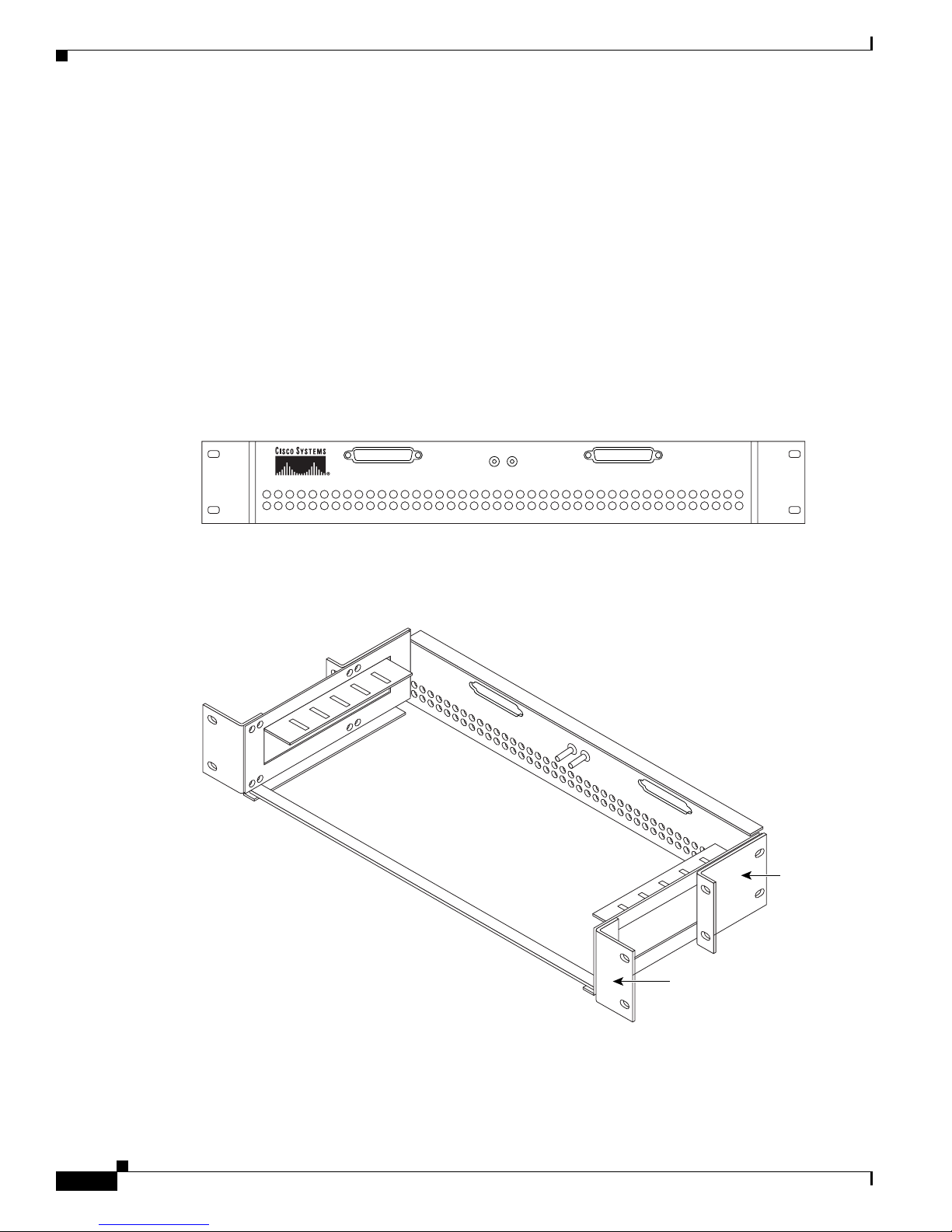
With the E1-75/120 conversion panel, each E1-42 port operates at 2.048 Mbps over a 75-ohm unbalanced
coaxial 1.0/2.3 miniature coaxial connector. Figure 1 shows the E1-75/120 faceplate.
Figure 1 E1-75/120 Conversion Panel Faceplate
1 2 3 4 5 6 7 8 9 10 11 12 13 14 15 16 17 18 19 20 21 22 23 24 25 26 22 28 29 30 31 32 33 34 35 36 37 38 39 40 41 42
Figure 2 shows the E1-75/120 with optional rackmount brackets installed.
Figure 2 E1-75/120 with Optional Rackmount Brackets
83635
19 to 23 in.
rackmount
bracket
Installing the Cisco ONS 15454 SDH E1-75/120 Impedance Conversion Panel
2
ETSI
rackmount
bracket
83636
78-15140-01
Page 3
E1-75/120 Impedance Conversion Panel Description
You can install the E1-75/120 conversion panel in the ANSI or ETSI rack containing the
ONS 15454 SDH shelf or in a nearby rack. If you install the E1-75/120 conversion panel where a longer
cable is required, make sure that the total cable loss of the balanced 120-ohm cable and the unbalanced
75-ohm cable does not exceed the maximum allowed value. The E1-75/120 conversion panel enables the
use of 75-ohm interfaces on the client side with the E1-42 card that has 120-ohm interfaces.
Before you can install the E1-75/120 in the rack, install the type of rackmount brackets that is required
for the rack that you are using. Figure 2 shows an ETSI rackmount bracket and a 19-inch/23-inch
rackmount bracket. To install the E1-75 in a 23-inch rack, use the 19-inch/23-inch rackmount brackets
perpendicularly.
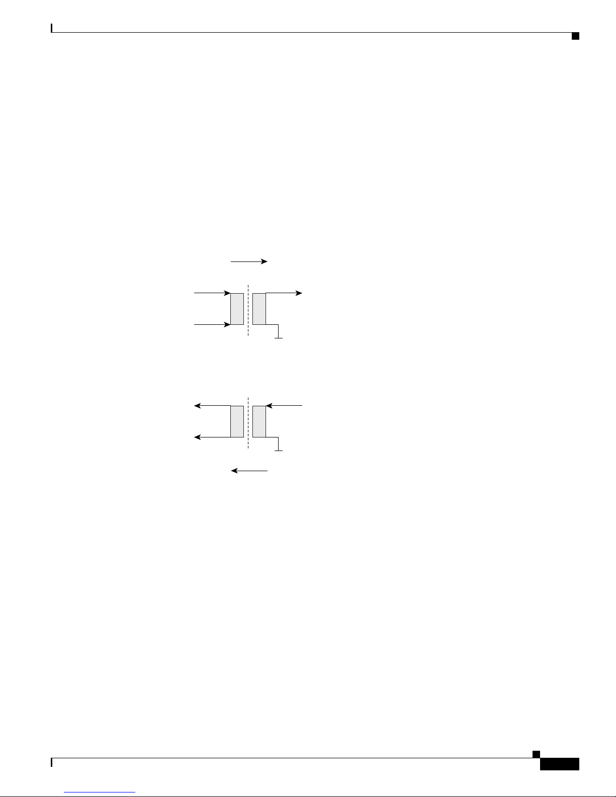
Figure 3 shows a block diagram of the E1-75/120 conversion panel.
Figure 3 E1-75/120 Conversion Panel Block Diagram
42 Channels
Transformer 1.26:1
120-Ohm
Symmetrical Signals
Transformer 1.26:1
42 Channels
75-Ohm
Unsymmetrical Signals
83637
E1-75/120 Impedance Conversion Panel Specifications
The E1-75/120 conversion panel has the following specifications:
• E1-75/120 input
–
Bit rate: 2.048 Mbps +/− 50 ppm
–
Line code: HDB-3
• E1-75/120 output
–
Bit rate: 2.048 Mbps +/− 50 ppm
–
Line code: HDB-3
• E1-75/120 electrical interface
78-15140-01
Installing the Cisco ONS 15454 SDH E1-75/120 Impedance Conversion Panel
3
Page 4

Install the E1-75/120 Conversion Panel
–
Connectors:
1.0/2.3 miniature coax connectors on 75-ohm side
Molex 96-pin LFH connectors on 120-ohm side (21 inputs and 21 outputs per connector)
–
Impedance tolerance: +/− 5%
Note See the cable loss specification of the E1-42 card for valid cable lengths. The E1-75/120 as a passive
device cannot amplify any singal and so cannot increase the possible cable length.
• Environmental
–
Operating temperature: –5 to +45 degrees Celsius (+23 to +113 degrees Fahrenheit)
–
Operating humidity: 5 to 95%, noncondensing
–
Power consumption: Not applicable; the E1-75/120 is a passive device.
• Dimensions
–
Height: 75 mm (2.95 in.)
–
Width: 535 mm (21.06 in.)
–
Depth: 221 mm (8.7 in.)
–
Weight: 2.15 kg (4.74 lb)
• Compliance
ONS 15454 SDH cards, when installed in a system, comply with these standards:
–
Safety: IEC 60950, EN 60950, UL 60950, CSA C22.2 No. 60950, TS 001, AS/NZS 3260
Install the E1-75/120 Conversion Panel
This section explains how to install the E1-75/120 conversion panel. You need an E1-75/120 conversion
panel if you want to convert the balanced 120-ohm interfaces of the E1-42 card and the corresponding
FMECs to unbalanced 75-ohm interfaces.
Note For more information about the E1-75/120 conversion panel, refer to the Cisco ONS 15454 Reference
Manual.
Step 1 Lift the E1-75/120 conversion panel to the desired rack position.
Figure 4 shows the rack-mounting for the E1-75/120 conversion panel.
Installing the Cisco ONS 15454 SDH E1-75/120 Impedance Conversion Panel
4
78-15140-01
Page 5

Figure 4 Mounting the E1-75/120 Conversion Panel in a Rack
Equipment rack
Install Ground and Cables
Step 2
Step 3 Using screws suitable to the rack that you are using, install one mounting screw in each side of the
Align the screw holes on the mounting ears with the mounting holes in the rack.
assembly.
Step 4 When the E1-75/120 conversion panel is secured to the rack, install the remaining mounting screws if
necessary.
Install Ground and Cables
This section explains how to install the ground connection and the cables to the E1-75/120 conversion
panel.
Install the Ground Connection
This section explains how to install the ground connection to the E1-75/120 conversion panel.
The ground connection is in the center of the faceplate of the E1-75/120 conversion panel.
83912
Step 1 Remove the nuts and washers from the two grounding bolts in the center of the faceplate.
Step 2 Remove the two-hole grounding lug from the two grounding bolts.
Step 3 With a crimping tool, crimp the ground cable (13.3 mm² [#6 AWG] multi-strand copper wire) to the
grounding lug.
Step 4 Attach the grounding lug to the two grounding bolts. Place the side with the ground cable to the side
where you want to route the grounding cable.
78-15140-01
Installing the Cisco ONS 15454 SDH E1-75/120 Impedance Conversion Panel
5
Page 6

Install Ground and Cables
Step 5 Use the nuts and washers to fix the grounding lug to the grounding bolts.
Step 6 Route the grounding cable and fix it to the to the loop farthest from the front of the cable guiding rail
using tiewraps.
Install Cables with Molex 96-Pin LFH Connectors on 120-Ohm Side
This section explains how to install the Molex 96-pin LFH connector cables on the 120-ohm side to the
E1-75/120 conversion panel.
Step 1 Guide the left Molex 96-pin LFH connector cable (channels 1 to 21) to the left and use tiewraps to attach
it to the loop farthest from the front-left side of the cable guiding rail ( see Figure 1 and Figure 2 on
page -2).
Step 2 Guide the right Molex 96-pin LFH connector cable (channels 22 to 42) to the right and use tiewraps to
attach it to the loop farthest from the front-right side of the cable guiding rail.
Install Cables with 1.0/2.3 Miniature Coax Connectors on 75-Ohm Side
This section explains how to install the 1.0/2.3 miniature coax connector cables on the 75-ohm side to
the E1-75/120 conversion panel.
Step 1 Group the 42 pairs of 75-ohm cables into six groups of 7 cable pairs, so that three groups of cables
(channels 1 to 7, channels 8 to 14, and channels 15 to 21) can be guided to the left and three groups of
cables (channels 42 to 36, channels 35 to 29, and channels 28 to 22) can be guided to the right.
Step 2 Tiewrap the two groups of cables coming from the left and right sides of the E1-75/120 conversion panel
(channels 1 to 7 and 42 to 36) to the second tiewrap fixing loop left and right, etc. with the following
groups (8-14, 35-29).
Step 3 Tiewrap the last two groups of cables coming from the left and right of the center of the E1-75/120
conversion panel (channels 15 to 21 and 28 to 22) to the left and right tiewrap fixing loops closest to the
front.
Step 4 Insert the 1.0/2.3 miniature coax connector of each cable into the connector of the E1-75/120 conversion
panel and push the connector until it clicks into position. If required, use the Y-shape end of the coaxial
connector insertion and removal tool.
Replace Cables with 1.0/2.3 Miniature Coax Connectors on 75-Ohm Side
This section explains how to replace single 1.0/2.3 miniature coax connector cables on the 75-ohm side
of the E1-75/120 conversion panel.
Step 1 If you want to replace individual 1.0/2.3 miniature coax connector cables in the existing installation, first
cut the tiewrap holding the cable that you want to replace.
Installing the Cisco ONS 15454 SDH E1-75/120 Impedance Conversion Panel
6
78-15140-01
Page 7

Step 2 With the Y-shape end of the coaxial connector insertion and removing tool, grab the groove of the 1.0/2.3
miniature coax connector, pull the sleave of the 1.0/2.3 miniature coax connector backwards, and remove
the connector and cable.
Step 3 Insert the 1.0/2.3 miniature coax connector of the new cable into the connector of the E1-75/120
conversion panel.
Step 4 With the Y-shape end of the coaxial connector insertion and removal tool, push the connector until it
clicks into position.
Step 5 Tie the cable with a tiewrap to the group of cables that it belongs to.
Related Documentation
• Cisco ONS 15454 SDH Procedure Guide
• Cisco ONS 15454 SDH Reference Manual
Related Documentation
Obtaining Documentation
Cisco provides several ways to obtain documentation, technical assistance, and other technical
resources. These sections explain how to obtain technical information from Cisco Systems.
Cisco.com
You can access the most current Cisco documentation on the World Wide Web at this URL:
http://www.cisco.com/univercd/home/home.htm
You can access the Cisco website at this URL:
http://www.cisco.com
International Cisco web sites can be accessed from this URL:
http://www.cisco.com/public/countries_languages.shtml
Documentation CD-ROM
Cisco documentation and additional literature are available in a Cisco Documentation CD-ROM
package, which may have shipped with your product. The Documentation CD-ROM is updated monthly
and may be more current than printed documentation. The CD-ROM package is available as a single unit
or through an annual subscription.
Registered Cisco.com users can order the Documentation CD-ROM (product number
DOC-CONDOCCD=) through the online Subscription Store:
http://www.cisco.com/go/subscription
78-15140-01
Installing the Cisco ONS 15454 SDH E1-75/120 Impedance Conversion Panel
7
Page 8

Obtaining Technical Assistance
Ordering Documentation
You can find instructions for ordering documentation at this URL:
http://www.cisco.com/univercd/cc/td/doc/es_inpck/pdi.htm
You can order Cisco documentation in these ways:
• Registered Cisco.com users (Cisco direct customers) can order Cisco product documentation from
the Networking Products MarketPlace:
http://www.cisco.com/en/US/partner/ordering/index.shtml
• Registered Cisco.com users can order the Documentation CD-ROM (Customer Order Number
DOC-CONDOCCD=) through the online Subscription Store:
http://www.cisco.com/go/subscription
• Nonregistered Cisco.com users can order documentation through a local account representative by
calling Cisco Systems Corporate Headquarters (California, U.S.A.) at 408 526-7208 or, elsewhere
in North America, by calling 800 553-NETS (6387).
Documentation Feedback
You can submit comments electronically on Cisco.com. On the Cisco Documentation home page, click
Feedback at the top of the page.
You can e-mail your comments to bug-doc@cisco.com.
You can submit your comments by mail by using the response card behind the front cover of your
document or by writing to the following address:
Cisco Systems
Attn: Customer Document Ordering
170 West Tasman Drive
San Jose, CA 95134-9883
We appreciate your comments.
Obtaining Technical Assistance
Cisco provides Cisco.com, which includes the Cisco Technical Assistance Center (TAC) Website, as a
starting point for all technical assistance. Customers and partners can obtain online documentation,
troubleshooting tips, and sample configurations from the Cisco TAC website. Cisco.com registered users
have complete access to the technical support resources on the Cisco TAC website, including TAC tools
and utilities.
Cisco.com
Cisco.com offers a suite of interactive, networked services that let you access Cisco information,
networking solutions, services, programs, and resources at any time, from anywhere in the world.
Cisco.com provides a broad range of features and services to help you with these tasks:
• Streamline business processes and improve productivity
• Resolve technical issues with online support
Installing the Cisco ONS 15454 SDH E1-75/120 Impedance Conversion Panel
8
78-15140-01
Page 9

• Download and test software packages
• Order Cisco learning materials and merchandise
• Register for online skill assessment, training, and certification programs
To obtain customized information and service, you can self-register on Cisco.com at this URL:
http://www.cisco.com
Technical Assistance Center
The Cisco TAC is available to all customers who need technical assistance with a Cisco product,
technology, or solution. Two levels of support are available: the Cisco TAC website and the Cisco TAC
Escalation Center. The avenue of support that you choose depends on the priority of the problem and the
conditions stated in service contracts, when applicable.
We categorize Cisco TAC inquiries according to urgency:
• Priority level 4 (P4)—You need information or assistance concerning Cisco product capabilities,
product installation, or basic product configuration.
• Priority level 3 (P3)—Your network performance is degraded. Network functionality is noticeably
impaired, but most business operations continue.
Obtaining Technical Assistance
Cisco TAC Website
You can use the Cisco TAC website to resolve P3 and P4 issues yourself, saving both cost and time. The
site provides around-the-clock access to online tools, knowledge bases, and software. To access the
Cisco TAC website, go to this URL:
http://www.cisco.com/tac
All customers, partners, and resellers who have a valid Cisco service contract have complete access to
the technical support resources on the Cisco TAC website. Some services on the Cisco TAC website
require a Cisco.com login ID and password. If you have a valid service contract but do not have a login
ID or password, go to this URL to register:
http://tools.cisco.com/RPF/register/register.do
If you are a Cisco.com registered user, and you cannot resolve your technical issues by using the Cisco
TAC website, you can open a case online at this URL:
http://www.cisco.com/en/US/support/index.html
If you have Internet access, we recommend that you open P3 and P4 cases through the Cisco TAC
website so that you can describe the situation in your own words and attach any necessary files.
• Priority level 2 (P2)—Your production network is severely degraded, affecting significant aspects
of business operations. No workaround is available.
• Priority level 1 (P1)—Your production network is down, and a critical impact to business operations
will occur if service is not restored quickly. No workaround is available.
78-15140-01
Installing the Cisco ONS 15454 SDH E1-75/120 Impedance Conversion Panel
9
Page 10

Obtaining Additional Publications and Information
Cisco TAC Escalation Center
The Cisco TAC Escalation Center addresses priority level 1 or priority level 2 issues. These
classifications are assigned when severe network degradation significantly impacts business operations.
When you contact the TAC Escalation Center with a P1 or P2 problem, a Cisco TAC engineer
automatically opens a case.
To obtain a directory of toll-free Cisco TAC telephone numbers for your country, go to this URL:
http://www.cisco.com/warp/public/687/Directory/DirTAC.shtml
Before calling, please check with your network operations center to determine the level of Cisco support
services to which your company is entitled: for example, SMARTnet, SMARTnet Onsite, or Network
Supported Accounts (NSA). When you call the center, please have available your service agreement
number and your product serial number.
Obtaining Additional Publications and Information
Information about Cisco products, technologies, and network solutions is available from various online
and printed sources.
• The Cisco Product Catalog describes the networking products offered by Cisco Systems as well as
ordering and customer support services. Access the Cisco Product Catalog at this URL:
http://www.cisco.com/en/US/products/products_catalog_links_launch.html
• Cisco Press publishes a wide range of networking publications. Cisco suggests these titles for new
and experienced users: Internetworking Terms and Acronyms Dictionary, Internetworking
Technology Handbook, Internetworking Troubleshooting Guide, and the Internetworking Design
Guide. For current Cisco Press titles and other information, go to Cisco Press online at this URL:
http://www.ciscopress.com
• Pack et magazine is the Cisco monthly periodical that provides industry professionals with the latest
information about the field of networking. You can access Pa cke t magazine at this URL:
http://www.cisco.com/en/US/about/ac123/ac114/about_cisco_packet_magazine.html
• Internet Protocol Journal is a quarterly journal published by Cisco Systems for engineering
professionals involved in the design, development, and operation of public and private internets and
intranets. You can access the Internet Protocol Journal at this URL:
http://www.cisco.com/en/US/about/ac123/ac147/about_cisco_the_internet_protocol_journal.html
• Training—Cisco offers world-class networking training, with current offerings in network training
listed at this URL:
http://www.cisco.com/en/US/learning/le31/learning_recommended_training_list.html
This document is to be used in conjunction with the documents listed in the “Related Documentation” section.
Installing the Cisco ONS 15454 SDH E1-75/120 Impedance Conversion Panel
10
78-15140-01
Page 11

Obtaining Additional Publications and Information
CCVP, the Cisco logo, and Welcome to the Human Network are trademarks of Cisco Systems, Inc.; Changing the Way We Work, Live, Play, and Learn is
a service mark of Cisco Systems, Inc.; and Access Registrar, Aironet, Catalyst, CCDA, CCDP, CCIE, CCIP, CCNA, CCNP, CCSP, Cisco, the Cisco
Certified Internetwork Expert logo, Cisco IOS, Cisco Press, Cisco Systems, Cisco Systems Capital, the Cisco Systems logo, Cisco Unity,
Enterprise/Solver, EtherChannel, EtherFast, EtherSwitch, Fast Step, Follow Me Browsing, FormShare, GigaDrive, HomeLink, Internet Quotient, IOS,
iPhone, IP/TV, iQ Expertise, the iQ logo, iQ Net Readiness Scorecard, iQuick Study, LightStream, Linksys, MeetingPlace, MGX, Networkers,
Networking Academy, Network Registrar, PIX, ProConnect, ScriptShare, SMARTnet, StackWise, The Fastest Way to Increase Your Internet Quotient,
and TransPath are registered trademarks of Cisco Systems, Inc. and/or its affiliates in the United States and certain other countries.
All other trademarks mentioned in this document or Website are the property of their respective owners. The use of the word partner does not imply a
partnership relationship between Cisco and any other company. (0711R)
Copyright © 2003 Cisco Systems, Inc. All rights reserved.
78-15140-01
Installing the Cisco ONS 15454 SDH E1-75/120 Impedance Conversion Panel
11
Page 12

Obtaining Additional Publications and Information
Installing the Cisco ONS 15454 SDH E1-75/120 Impedance Conversion Panel
12
78-15140-01
 Loading...