

Page 1

CHA PTER
5
Ethernet Cards
Note The terms “Unidirectional Path Switched Ring” and “UPSR” may appear in Cisco literature. These terms
do not refer to using Cisco ONS 15xxx products in a unidirectional path switched ring configuration.
Rather, these terms, as well as “Path Protected Mesh Network” and “PPMN,” refer generally to Cisco’s
path protection feature, which may be used in any topological network configuration. Cisco does not
recommend using its path protection feature in any particular topological network configuration.
The Cisco ONS 15454 SDH integrates Ethernet into a SDH time-division multiplexing (TDM) platform.
This chapter describes the Cisco ONS 15454 SDH E-Series Ethernet cards, G-Series Ethernet cards, and
ML-Series Ethernet cards. It includes descriptions, hardware specifications, and block diagrams for each
card. For G-Series and E-Series Ethernet application information, see Chapter 14, “Ethernet Operation.”
For installation and card turn-up procedures, refer to the Cisco ONS 15454 SDH Procedure Guide. For
ML-Series configuration information, see the Ethernet Card Software Feature and Configuration Guide.
Chapter topics include:
• 5.1 Ethernet Card Overview, page 5-1
• 5.2 E100T-G Card, page 5-2
• 5.3 E1000-2-G Card, page 5-4
• 5.4 G1000-4 Card, page 5-7
• 5.5 G1K-4 Card, page 5-8
• 5.6 ML100T-12 Card, page 5-10
• 5.7 ML1000-2 Card, page 5-12
• 5.8 GBICs and SFPs, page 5-14
5.1 Ethernet Card Overview
The card overview section summarizes card functions, power consumption, and temperature ranges.
Note Each card is marked with a symbol that corresponds to a slot (or slots) on the ONS 15454 SDH shelf
assembly. The cards are then installed into slots displaying the same symbols. See the
Cisco ONS 15454 SDH Procedures Guide for a list of slots and symbols.
April 2008
Cisco ONS 15454 SDH Reference Manual, R5.0
5-1
Page 2

5.1.1 Cards Summary
5.1.1 Cards Summary
Table 5-1 lists the Cisco ONS 15454 SDH Ethernet cards.
Table 5-1 Ethernet Cards for the ONS 15454 SDH
Card Port Description For Additional Information...
E100T-G The E100T-G card provides 12 switched, autosensing,
E1000-2-G The E1000-2-G card provides two IEEE-compliant,
G1000-4 The G1000-4 card provides four IEEE-compliant,
G1K-4 The G1K-4 card provides four IEEE-compliant,
ML100T-12 The ML100T-12 card provides 12 switched,
ML1000-2 The ML1000-2 card provides two IEEE-compliant,
10/100BaseT Ethernet ports.
1000-Mbps ports. Gigabit Interface Converters
(GBICs) are separate.
1000-Mbps ports. GBICs are separate.
1000-Mbps ports. GBICs are separate. The G1K-4 card
is functionally identical to the G1000-4 card.
autosensing, 10/100Base-T Ethernet ports.
1000-Mbps ports. Small form-factor pluggable (SFP)
connectors are separate.
Chapter 5 Ethernet Cards
See the “5.2 E100T-G Card”
section on page 5-2.
See the “5.3 E1000-2-G Card”
section on page 5-4.
See the “5.4 G1000-4 Card”
section on page 5-7.
See the “5.5 G1K-4 Card”
section on page 5-8.
See the “5.6 ML100T-12
Card” section on page 5-10.
See the “5.7 ML1000-2 Card”
section on page 5-12.
5.1.2 Card Compatibility
Table 5-2 lists the CTC software compatibility for each Ethernet card. See Table 2-6 on page 2-4 to
determine Ethernet card cross-connect compatibility.
Table 5-2 Ethernet Card Software Compatibility
Ethernet
Cards R2.2.1 R2.2.2 R3.0.1 R3.1 R3.2 R3.3 R3.4 R4.0 R4.1 R4.5
E100T-G
E1000-2-G
G1000-4
G1K-4
ML100T-12
ML1000-2
1. DWDM-only release.
Yes Yes Yes Yes Yes Yes Yes Yes Ye s — Ye s — Yes
Yes Yes Yes Ye s Ye s Ye s Yes Yes Ye s — Ye s — Yes
— — — — Yes Yes Yes Yes Ye s — Ye s — Yes
— — — — Yes Yes Yes Yes Ye s — Ye s — Yes
— — — — — — — Ye s Ye s — Ye s — Yes
— — — — — — — Ye s Ye s — Ye s — Yes
5.2 E100T-G Card
The ONS 15454 SDH uses E100T-G cards for Ethernet (10 Mbps) and Fast Ethernet (100 Mbps). Each
card provides 12 switched, IEEE 802.3-compliant, 10/100BaseT Ethernet ports that can independently
detect the speed of an attached device (autosense) and automatically connect at the appropriate speed.
1
R4.6 R4.71R5.0
5-2
Cisco ONS 15454 SDH Reference Manual, R5.0
April 2008
Page 3
Chapter 5 Ethernet Cards
5.2 E100T-G Card
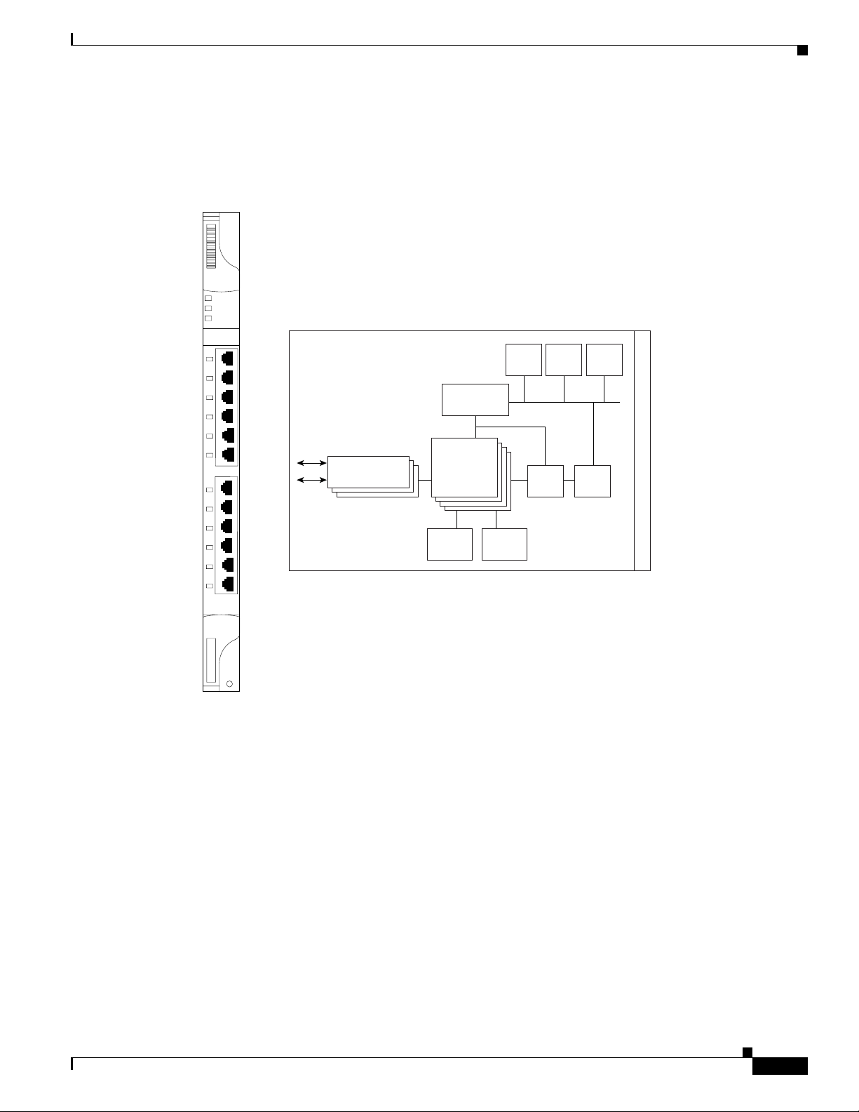
The ports autoconfigure to operate at either half or full duplex and determine whether to enable or
disable flow control. You can also configure Ethernet ports manually. Figure 5-1 shows the faceplate and
a block diagram of the card.
Figure 5-1 E100T-G Faceplate and Block Diagram
E100T-G
FAIL
ACT
SF
1
2
3
4
5
6
10/100
7
8
9
10
11
12
PHYS
A/D Mux
Ethernet
MACs/switch
Buffer
memory
Control
memory
Flash
FPGA BTC
DRAM
CPU
B
a
c
k
p
l
a
n
e
61877
The E100T-G Ethernet card provides high-throughput, low-latency packet switching of Ethernet traffic
across a SDH network while providing a greater degree of reliability through SDH self-healing
protection services. This Ethernet capability enables network operators to provide multiple
10/100-Mbps access drops for high-capacity customer LAN interconnects, Internet traffic, and cable
modem traffic aggregation. It enables the efficient transport and co-existence of traditional TDM traffic
with packet-switched data traffic.
April 2008
Each E100T-G card supports standards-based, wire-speed, Layer 2 Ethernet switching between its
Ethernet interfaces. The IEEE 802.1Q tag logically isolates traffic (typically subscribers). IEEE 802.1Q
also supports multiple classes of service.
Cisco ONS 15454 SDH Reference Manual, R5.0
5-3
Page 4

5.2.1 E100T-G Slot Compatibility
5.2.1 E100T-G Slot Compatibility
You can install the E100T-G card in Slots 1 to 6 and 12 to 17. Multiple E-Series Ethernet cards installed
in an ONS 15454 SDH can act independently or as a single Ethernet switch. You can create logical SDH
ports by provisioning a number of SDH channels to the packet switch entity within the ONS 15454 SDH.
Logical ports can be created with a bandwidth granularity of VC-4.
5.2.2 E100T-G Card-Level Indicators
The E100T-G card faceplate has three card-level LED indicators (Tabl e 5-3 ).
Ta b l e 5 - 3 E 10 0 T- G C a r d - L e v e l Indica to r s
Card-Level Indicators Description
Red FAIL LED The red FAIL LED indicates that the card’s processor is not ready or that a
catastrophic software failure occurred on the E100T-G card. As part of the
boot sequence, the FAIL LED is turned on until the software deems the card
operational.
Green ACT LED A green ACT LED provides the operational status of the E100T-G. If the
ACT LED is green, it indicates that the E100T-G card is active and the
software is operational.
SF LED Not used.
Chapter 5 Ethernet Cards
5.2.3 E100T-G Port-Level Indicators
The E100T-G card also has 12 pairs of LEDs (one pair for each port) to indicate port conditions
(Tabl e 5-4 ). You can find the status of the E100T-G card port using the LCD screen on the
ONS 15454 SDH fan-tray assembly. Use the LCD to view the status of any port or card slot; the screen
displays the number and severity of alarms for a given port or slot.
Table 5-4 E100T-G Port-Level Indicators
LED State Description
Amber Port is active (transmitting and/or receiving data). By default, indicates the
transmitter is active but can be software controlled to indicate link status,
duplex status, or receiver active.
Solid Green Link is established. By default, indicates the link for this port is up, but can
be software controlled to indicate duplex status, operating speed, or
collision.
5.3 E1000-2-G Card
The ONS 15454 SDH uses E1000-2-G cards for Gigabit Ethernet (1000 Mbps). The E1000-2-G card
provides two IEEE-compliant, 1000-Mbps ports for high-capacity customer LAN interconnections.
Each port supports full-duplex operation.
5-4
Cisco ONS 15454 SDH Reference Manual, R5.0
April 2008
Page 5
Chapter 5 Ethernet Cards
5.3 E1000-2-G Card
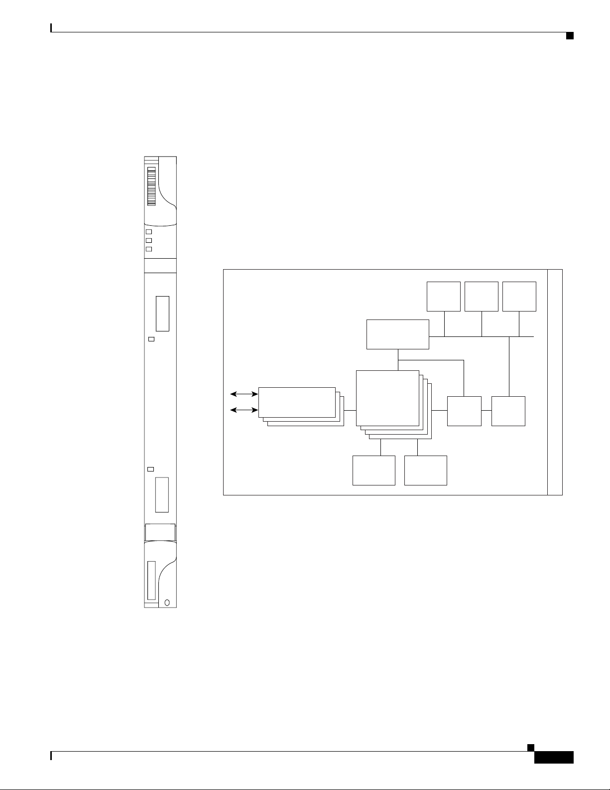
The E1000-2-G card uses GBIC modular receptacles for the optical interfaces. For details, see the
“5.8 GBICs and SFPs” section on page 5-14.
Figure 5-2 shows the card faceplate and a block diagram of the card.
Figure 5-2 E1000-2-G Faceplate and Block Diagram
E1000-2-G
FAIL
ACT
SF
RX
1
TX
ACT/LINK
ACT/LINK
RX
2
TX
33678 12931
Gigabit Ethernet
PHYS
A/D Mux
Ethernet
MACs/switch
Buffer
memory
Flash
Control
memory
DRAM
FPGA BTC
CPU
B
a
c
k
p
l
a
n
e
61878
April 2008
The E1000-2-G Gigabit Ethernet card provides high-throughput, low-latency packet switching of
Ethernet traffic across a SDH network while providing a greater degree of reliability through SDH
self-healing protection services. This enables network operators to provide multiple 1000-Mbps access
drops for high-capacity customer LAN interconnects. It enables efficient transport and co-existence of
traditional TDM traffic with packet-switched data traffic.
Cisco ONS 15454 SDH Reference Manual, R5.0
5-5
Page 6

5.3.1 E1000-2-G Compatibility
Each E1000-2-G card supports standards-based, Layer 2 Ethernet switching between its Ethernet
interfaces and SDH interfaces on the ONS 15454 SDH. The IEEE 802.1Q VLAN tag logically isolates
traffic (typically subscribers).
Multiple E-Series Ethernet cards installed in an ONS 15454 SDH can act together as a single switching
entity or as independent single switches supporting a variety of SDH port configurations.
You can create logical SDH ports by provisioning a number of SDH channels to the packet switch entity
within the ONS 15454 SDH. Logical ports can be created with a bandwidth granularity of VC-4.
5.3.1 E1000-2-G Compatibility
The E1000-2-G is compatible with any traffic card slots (Slots 1 to 6 and 12 to 17).
5.3.2 E1000-2-G Card-Level Indicators
The E1000-2-G card faceplate has three card-level LED indicators (Table 5-5 ).
Table 5-5 E1000-2-G Card-Level Indicators
Chapter 5 Ethernet Cards
Card-Level Indicators Description
Red FAIL LED The red FAIL LED indicates that the card’s processor is not ready or that a
catastrophic software failure occurred on the E1000-2-G card. As part of the
boot sequence, the FAIL LED is turned on until the software deems the card
operational.
Green ACT LED A green ACT LED provides the operational status of the E1000-2-G. If the
ACT LED is green it indicates that the E1000-2-G card is active and the
software is operational.
SF LED Not used in this release.
5.3.3 E1000-2-G Port-Level Indicators
The E1000-2-G card also has one bicolor LED per port (Table 5-6). When the LINK LED is illuminated
green, carrier is detected, meaning an active network cable is installed. When the LINK LED is not
illuminated green, an active network cable is not plugged into the port, or the card is carrying
unidirectional traffic. The port ACT LED flashes amber at a rate proportional to the level of traffic being
received and transmitted over the port.
Table 5-6 E1000-2-G Port-Level Indicators
LED State Description
Amber The port is active (transmitting and receiving data).
Solid green The link is established.
Green light off The connection is inactive, or traffic is unidirectional.
5-6
Cisco ONS 15454 SDH Reference Manual, R5.0
April 2008
Page 7

Chapter 5 Ethernet Cards
5.4 G1000-4 Card
The ONS 15454 SDH uses G1000-4 cards for Gigabit Ethernet (1000 Mbps). The G1000-4 card
provides four ports of IEEE-compliant, 1000-Mbps interfaces. Each port supports full-duplex operation
for a maximum bandwidth of STM-16 on each card.
The G1000-4 card uses GBIC modular receptacles for the optical interfaces. For details, see the
“5.8 GBICs and SFPs” section on page 5-14.
Figure 5-3 shows the card faceplate and the block diagram of the card.
Figure 5-3 G1000-4 Faceplate and Block Diagram
G1000
4
FAIL
ACT
5.4 G1000-4 Card
RX
1
TX
ACT/LINK
RX
2
TX
ACT/LINK
RX
3
TX
ACT/LINK
RX
4
TX
ACT/LINK
Flash DRAM CPU
GBICs
Trans-
ceivers
Powe r
Ethernet
MACs/switch
Clock
Generation
Decode
PLD
Mux/
Demux
FPGA
To FPGA, BTC,
MACs
Inter-
face
FPGA
Buffer
memory
POS
Function
BTC
Protect/
Main
Rx/Tx
BPIAs
B
a
c
k
p
l
a
n
e
67863
April 2008
The G1000-4 Gigabit Ethernet card provides high-throughput, low latency transport of Ethernet
encapsulated traffic (IP and other Layer 3 protocols) across a SDH network. Carrier-class Ethernet
transport is achieved by hitless (< 50 ms) performance in the event of any failures or protection switches
(such as 1+1 automatic protection switching [APS], SNCP ring, or MS-SPRing. Full provisioning
support is possible via Cisco Transport Controller (CTC) or Cisco Transport Manager (CTM). Each
G1000-4 card performs independently of the other cards in the same shelf.
Cisco ONS 15454 SDH Reference Manual, R5.0
5-7
Page 8

5.4.1 G1000-4 Card-Level Indicators
5.4.1 G1000-4 Card-Level Indicators
The G1000-4 card faceplate has two card-level LED indicators (Table 5-7 ).
Table 5-7 G1000-4 Card-Level Indicators
Card-Level LEDs Description
FAIL LED (red) The red FAIL LED indicates that the card’s processor is not ready or that a
catastrophic software failure occurred on the G1000-4 card. As part of the
boot sequence, the FAIL LED turns on; it turns off if the software is deemed
operational.
The red FAIL LED normally blinks when the card is loading software.
ACT LED (green) A green ACT LED provides the operational status of the G1000-4. If the
ACT LED is green, it indicates that the G1000-4 card is active and the
software is operational.
5.4.2 G1000-4 Port-Level Indicators
Chapter 5 Ethernet Cards
The G1000-4 card has one bicolor LED per port. Tab le 5 -8 describes the status that each color
represents.
Table 5-8 G1000-4 Port-Level Indicators
Port-Level LED State Description
Off No link exists to the Ethernet port.
Steady amber A link exists to the Ethernet port, but traffic flow is inhibited. For example,
Solid green A link exists to the Ethernet port, but no traffic is carried on the port.
Flashing green A link exists to the Ethernet port, and traffic is carried on the port. The LED
5.4.3 G1000-4 Compatibility
The G-Series card operates in Slots 1 to 6 and 12 to 17, for a total shelf capacity of 48 Gigabit Ethernet
ports. The practical G1000-4 port per shelf limit is 40, because at least two slots are typically filled by
OC-N trunk cards.
an unconfigured circuit, an error on line, or a nonenabled port might inhibit
traffic flow.
flash rate reflects the traffic rate for the port.
5.5 G1K-4 Card
The G1K-4 card is the functional equivalent of the G1000-4 card and provides four ports of
IEEE-compliant, 1000-Mbps interfaces. Each interface supports full-duplex operation for a maximum
bandwidth of 1 Gbps or 2 Gbps bidirectional per port, and 2.5 Gbps or 5 Gbps bidirectional per card.
Each port autonegotiates for full duplex and IEEE 802.3x flow control. The G1K-4 card uses GBIC
modular receptacles for the optical interfaces. For details, see the “5.8 GBICs and SFPs” section on
page 5-14.
Cisco ONS 15454 SDH Reference Manual, R5.0
5-8
April 2008
Page 9

Chapter 5 Ethernet Cards
Figure 5-4 shows the card faceplate and the block diagram of the card.
Figure 5-4 G1K-4 Faceplate and Block Diagram
G1K
FAIL
ACT
5.5.1 G1K-4 Compatibility
RX
1
TX
ACT/LINK
RX
2
TX
ACT/LINK
RX
3
TX
ACT/LINK
RX
4
TX
ACT/LINK
Flash DRAM CPU
GBICs
Trans-
ceivers
Powe r
Ethernet
MACs/switch
Clock
generation
Decode
PLD
Mux/
Demux
FPGA
To FPGA, BTC,
MACs
Inter-
face
FPGA
Buffer
memory
POS
function
BTC
Protect/
Main
Rx/Tx
BPIAs
B
a
c
k
p
l
a
n
e
83649
The G1K-4 Gigabit Ethernet card provides high-throughput, low-latency transport of Ethernet
encapsulated traffic (IP and other Layer 3 protocols) across a SDH network while providing a greater
degree of reliability through SDH self-healing protection services. Carrier-class Ethernet transport is
achieved by hitless (< 50 ms) performance in the event of any failures or protection switches (such as
1+1 APS, path protection, BLSR, or optical equipment protection) and full provisioning and
manageability, as in SDH service. Full provisioning support is possible via CTC or CTM. Each G1K-4
card performs independently of the other cards in the same shelf.
5.5.1 G1K-4 Compatibility
Software R4.0 and later identifies G1K-4 cards as G1K-4s upon physical installation. Software prior to
R4.0 identifies both G1000-4 and G1K-4 cards as G1000-4s upon physical installation.
You can install the G1K-4 card in Slots 1 to 6 and 12 to 17, for a total shelf capacity of 48 Gigabit
Ethernet ports. (The practical limit is 40 ports because at least two slots are typically populated by
optical cards such as the OC-192.)
April 2008
Cisco ONS 15454 SDH Reference Manual, R5.0
5-9
Page 10

5.5.2 G1K-4 Card-Level Indicators
5.5.2 G1K-4 Card-Level Indicators
The G1K-4 card faceplate has two card-level LED indicators, described in Tab le 5- 9.
Table 5-9 G1K-4 Card-Level Indicators
Card-Level LEDs Description
FAIL LED (red) The red FAIL LED indicates that the card’s processor is not ready or that a
catastrophic software failure occurred on the G1K-4 card. As part of the boot
sequence, the FAIL LED is turned on, and it goes off when the software is
deemed operational.
The red FAIL LED blinks when the card is loading software.
ACT LED (green) A green ACT LED provides the operational status of the G1K-4. If the ACT
LED is green, it indicates that the G1K-4 card is active and the software is
operational.
5.5.3 G1K-4 Port-Level Indicators
Chapter 5 Ethernet Cards
The G1K-4 card has four bicolor LEDs (one LED per port). Table 5-10 describes these LEDs.
Table 5-10 G1K-4 Port-Level Indicators
Port-Level LED State Description
Off No link exists to the Ethernet port.
Steady amber A link exists to the Ethernet port, but traffic flow is inhibited. For example,
Solid green A link exists to the Ethernet port, but no traffic is carried on the port.
Flashing green A link exists to the Ethernet port, and traffic is carried on the port. The LED
5.6 ML100T-12 Card
The ML100T-12 card provides 12 ports of IEEE 802.3-compliant, 10/100 interfaces. Each interface
supports full-duplex operation for a maximum bandwidth of 200 Mbps per port and 2.488 Gbps per card.
Each port independently detects the speed of an attached device (autosenses) and automatically connects
at the appropriate speed. The ports autoconfigure to operate at either half or full duplex and can
determine whether to enable or disable flow control. For ML-Series configuration information, see the
Cisco ONS 15454 SONET/SDH ML-Series Multilayer Ethernet Card Software Feature and
Configuration Guide.
Figure 5-5 shows the card faceplate.
a lack of circuit setup, an error on the line, or a nonenabled port might inhibit
traffic flow.
flash rate reflects the traffic rate for the port.
5-10
Caution Shielded twisted-pair cabling should be used for inter-building applications.
Cisco ONS 15454 SDH Reference Manual, R5.0
April 2008
Page 11

Chapter 5 Ethernet Cards
Figure 5-5 ML100T-12 Faceplate
ML100T
12
ACT
FAIL
0
1
2
3
4
5
6
7
8
9
10
11
5.6.1 ML100T-12 Card-Level Indicators
83647
ML-Series cards feature two SDH virtual ports with a maximum combined bandwidth of VC4-16c. Each
port carries an STM circuit with a size of VC3, VC4, VC4-2c, VC4-3c, VC4-4c, and VC4-8c. For
step-by-step instructions on configuring an ML-Series card SDH STM circuit, refer to the “Create
Circuits and Tunnels” chapter of the Cisco ONS 15454 SDH Procedure Guide.
The ML-Series packet-over-SDH (POS) ports supports virtual concatenation (VCAT) of SONET/SDH
circuits and a software link capacity adjustment scheme (SW-LCAS). The ML-Series card supports a
maximum of two VCAT groups with each group corresponding to one of the POS ports. Each VCAT
group must be provisioned with two circuit members. An ML-Series card supports VC-3-2v, VC-4-2v
and VC-4-4c-2v. For step-by-step instructions on configuring an ML-Series card SDH VCAT circuit,
refer to the “Create Circuits and Tunnels” chapter of the Cisco ONS 15454 SDH Procedure Guide.
5.6.1 ML100T-12 Card-Level Indicators
The ML00T-12 card supports two card-level LED indicators, described in Ta ble 5-1 1.
April 2008
Cisco ONS 15454 SDH Reference Manual, R5.0
5-11
Page 12

5.6.2 ML100T-12 Port-Level Indicators
Chapter 5 Ethernet Cards
Table 5-11 ML100T-12 Card-Level Indicators
Card-Level LEDs Description
Red SF LED The red SF LED indicates that the card’s processor is not ready or that a
catastrophic software failure occurred on the ML100T-12 card. As part of the
boot sequence, the FAIL LED is illuminated until the software deems the
card operational.
Green ACT LED A green ACT LED provides the operational status of the ML100T-12. If the
ACT LED is green, it indicates that the ML100T-12 card is active and the
software is operational.
5.6.2 ML100T-12 Port-Level Indicators
The ML100T-12 card provides a pair of LEDs for each Fast Ethernet port: an amber LED for activity
(ACT) and a green LED for LINK. The port-level indicators are described in Tab le 5- 12.
Table 5-12 ML100T-12 Port-Level Indicators
Port-Level LED State Description
ACT LED (Amber) Steady amber LED indicates that a link is detected, but there is an
issue inhibiting traffic.
Blinking amber LED means that traffic is flowing.
LINK LED (Green) Steady green LED indicates that a link is detected, but there is no
traffic.
Blinking green LED flashes at a rate proportional to the level of traffic
being received and transmitted over the port.
Both ACT and LINK LED Unlit green and amber LEDs indicate no traffic.
5.6.3 ML100T-12 Slot Compatibility
The ML100T-12 card works in Slots 1 to 6 or 12 to 17.
5.7 ML1000-2 Card
The ML1000-2 card provides two ports of IEEE-compliant, 1000-Mbps interfaces. Each interface
supports full-duplex operation for a maximum bandwidth of 2 Gbps per port and 4 Gbps per card. Each
port autoconfigures for full duplex and IEEE 802.3x flow control.
SFP modules are offered as separate orderable products for maximum customer flexibility. For details,
see the “5.8 GBICs and SFPs” section on page 5-14.
Cisco ONS 15454 SDH Reference Manual, R5.0
5-12
April 2008
Page 13

Chapter 5 Ethernet Cards
Figure 5-6 shows the ML1000-2 card faceplate.
Figure 5-6 ML1000-2 Faceplate
ML1000
2
FAIL
ACT
CONSOLE
5.7.1 ML1000-2 Card-Level Indicators
TX
1
RX
LINK
ACT
TX
2
RX
LINK
ACT
83648
ML-Series cards feature two SDH virtual ports with a maximum combined bandwidth of VC4-16c. Each
port carries an STM circuit with a size of VC3, VC4, VC4-2c, VC4-3c, VC4-4c, and VC4-8c. For
step-by-step instructions on configuring an ML-Series card SDH STM circuit, refer to the “Create
Circuits and Tunnels” chapter of the Cisco ONS 15454 SDH Procedure Guide.
The ML-Series POS ports supports VCAT of SONET/SDH circuits and a software link capacity
adjustment scheme (SW-LCAS). The ML-Series card supports a maximum of two VCAT groups with
each group corresponding to one of the POS ports. Each VCAT group must be provisioned with two
circuit members. An ML-Series card supports VC-3-2v, VC-4-2v and VC-4-4c-2v. For step-by-step
instructions on configuring an ML-Series card SDH VCAT circuit, refer to the “Create Circuits and
Tunnels” chapter of the Cisco ONS 15454 SDH Procedure Guide.
5.7.1 ML1000-2 Card-Level Indicators
The ML1000-2 card faceplate has two card-level LED indicators, described in Ta ble 5- 13.
April 2008
Cisco ONS 15454 SDH Reference Manual, R5.0
5-13
Page 14

5.7.2 ML1000-2 Port-Level Indicators
Chapter 5 Ethernet Cards
Table 5-13 ML1000-2 Card-Level Indicators
Card-Level LEDs Description
FAIL LED (Red) The red FAIL LED indicates that the card’s processor is not ready or that a
catastrophic software failure occurred on the ML1000-2 card. As part of the
boot sequence, the FAIL LED is turned on until the software deems the card
operational.
ACT LED (Green) A green ACT LED provides the operational status of the ML1000-2. When
the ACT LED is green, it indicates that the ML1000-2 card is active and the
software is operational.
5.7.2 ML1000-2 Port-Level Indicators
The ML1000-2 card has two LEDs for each of the two Gigabit Ethernet ports. The port-level indicators
are described in Table 5-1 4.
Table 5-14 ML1000-2 Port-Level Indicators
Port-Level LED State Description
ACT LED (Amber) Steady amber LED indicates that a link is detected, but there is an issue
inhibiting traffic.
Blinking amber LED means that traffic is flowing.
LINK LED (Green) Steady green LED indicates that a link is detected, but there is no traffic.
Blinking green LED flashes at a rate proportional to the level of traffic
being received and transmitted over the port.
Both ACT and LINK LED Unlit green and amber LEDs indicate no traffic.
5.7.3 ML1000-2 Slot Compatibility
The ML1000-2 card works in Slots 1 to 6 or 12 to 17.
5.8 GBICs and SFPs
This section describes the GBICs and SFPs used with the Ethernet cards.
The ONS 15454 SDH Ethernet cards use industry standard small form-factor pluggable connectors
(SFPs) and Gigabit Interface Converter (GBIC) modular receptacles. The ML-Series Gigabit Ethernet
cards use standard Cisco SFPs. The Gigabit E-Series card and the G-Series card use standard Cisco
GBICs. With Software Release 4.1 and later, G-Series cards can also be equipped with dense wavelength
division multiplexing (DWDM) and coarse wavelength division multiplexing (CWDM) GBICs to
function as Gigabit Ethernet transponders.
For all Ethernet cards, the type of GBIC or SFP plugged into the card is displayed in CTC and TL1. Cisco
offers SFPs and GBICs as separate orderable products.
Cisco ONS 15454 SDH Reference Manual, R5.0
5-14
April 2008
Page 15

Chapter 5 Ethernet Cards
5.8.1 Compatibility by Card
Table 5-1 5 lists Cisco ONS 15454 SDH Ethernet cards with their compatible GBICs and SFPs.
Caution Only use GBICs and SFPs certified for use in Cisco Optical Networking Systems. The qualified Cisco
GBIC and SFP pluggable module’s top assembly numbers (TANs) are provided in Tabl e 5 -15.
Table 5-15 GBIC and SFP Card Compatibility
5.8.1 Compatibility by Card
Compatible GBIC or SFP
Card
E1000-2-G
(ONS 15454 SONET)
E1000-2 (ONS 15454 SONET/SDH)
(Cisco Product ID)
15454-GBIC-SX
15454E-GBIC-SX
15454-GBIC-LX/LH
15454E-GBIC-LX/LH
FC_MR-4 (ONS 15454 SONET/SDH) 15454-GBIC-SX
15454E-GBIC-SX
15454-GBIC-LX/LH
15454E-GBIC-LX/LH
ONS-GX-2FC-MMI
ONS-GX-2FC-SML
G1K-4
G1000-4 (ONS 15454 SONET/SDH)
(ONS 15454 SONET/SDH)
15454-GBIC-SX
15454E-GBIC-SX
15454-GBIC-LX/LH
15454E-GBIC-LX/LH
15454-GBIC-ZX
ML1000-2
15454E-GBIC-ZX
15454-GBIC-xx.x
15454E-GBIC-xx.x
15454-GBIC-xxxx
15454E-GBIC-xxxx
(ONS 15454 SONET/SDH) 15454-SFP-LC-SX
2
2
3
3
15454E-SFP-LC-SX
15454-SFP-LC-LX/LH
15454E-SFP-LC-LX/LH
1. This TAN is only compatible with ONS 15454-E1000-2 or 15454-E1000-2-G cards.
2. xx.x defines the 32 possible wavelengths as shown in Table A-1 on page A-4.
3. xxxx defines the 8 possible wavelengths as shown in Table 5-16 on page 5-17.
Cisco Top Assembly Number
(TAN)
30-0759-01
800-06780-01
10-1743-01
30-0703-01
30-0759-01
800-06780-01
10-1743-01
30-0703-01
10-2015-01
10-2016-01
30-0759-01
800-06780-01
10-1743-01
30-0703-01
30-0848-01
10-1744-01
10-1845-01 through 10-1876-01
10-1845-01 through 10-1876-01
10-1453-01 through 10-1460-01
10-1453-01 through 10-1460-01
30-1301-01
30-1301-01
30-1299-01
30-1299-01
1
5.8.2 GBIC Description
GBICs are integrated fiber optic transceivers that provide high speed serial links from a port or slot to
the network. Various latching mechanisms can be utilized on the GBIC pluggable modules. There is no
correlation between the type of latch to the model type (such as SX or LX/LH) or technology type (such
as Gigabit Ethernet). See the label on the GBIC for technology type and model. One GBIC model has
two clips (one on each side of the GBIC) that secure the GBIC in the slot on the Ethernet card; the other
has a locking handle. Both types are shown in Figure 5-7.
April 2008
Cisco ONS 15454 SDH Reference Manual, R5.0
5-15
Page 16

5.8.2 GBIC Description
Chapter 5 Ethernet Cards
GBIC dimensions are:
• Height 0.39 in. (1 cm)
• Width 1.18 in. (3 cm)
• Depth 2.56 in. (6.5 cm)
GBIC temperature ranges are:
• COM—commercial operating temperature range -5°C to 70°C
• EXT—extended operating temperature range 0°C to 85°C
• IND—industrial operating temperature range -40°C to 85°C
Figure 5-7 GBICs with Clips (left) and with a Handle (right)
Receiver
Transmitter
5.8.2.1 DWDM and CWDM GBICs
DWDM (15454-GBIC-xx.x, 15454E-GBIC-xx.x) and CWDM (15454-GBIC-xxxx,
15454E-GBIC-xxxx) GBICs operate in the ONS 15454 G-Series card when the card is configured in
Gigabit Ethernet Transponding mode or in Ethernet over SDH mode. DWDM and CWDM GBICs are
both wavelength division multiplexing (WDM) technologies and operate over single-mode fibers with SC
connectors. Cisco CWDM GBIC technology uses a 20 nm wavelength grid and Cisco ONS 15454 DWDM
GBIC technology uses a 1 nm wavelength grid. CTC displays the specific wavelengths of the installed
CWDM or DWDM GBICs. DWDM wavelengths are spaced closer together and require more precise lasers
than CWDM. The DWDM spectrum allows for optical signal amplification. For more information on
G-Series card transponding mode, see the Cisco ONS 15454 Reference Manual.
The DWDM and CWDM GBICs receive across the full 1300 nm and 1500 nm bands, which includes all
CWDM, DWDM, LX/LH, ZX wavelengths, but transmit on one specified wavelength. This capability
can be exploited in some of the G-Series transponding modes by receiving wavelengths that do not match
the specific transmission wavelength.
Note G1000-4 cards support CWDM and DWDM GBICs. G1K-4 cards with the Common Language
Equipment Identification (CLEI) code of WM5IRWPCAA (manufactured after August 2003) support
CWDM and DWDM GBICs. G1K-4 cards manufactured prior to August 2003 do not support CWDM or
DWDM GBICs.
Clip
Receiver
Transmitter
Handle
51178
5-16
The ONS 15454-supported CWDM GBICs reach up to 100 to 120 km over single-mode fiber and support
eight wavelengths as shown in Ta ble 5-16.
Cisco ONS 15454 SDH Reference Manual, R5.0
April 2008
Page 17

Chapter 5 Ethernet Cards
Table 5-16 Supported Wavelengths for CWDM GBICs
5.8.2 GBIC Description
CWDM GBIC Wavelengths
Corresponding GBIC Colors
Band
1470 nm 1490 nm 1510 nm 1530 nm 1550 nm 1570 nm 1590 nm 1610 nm
Gray Violet Blue Green Yellow Orange Red Brown
47 49 51 53 55 57 59 61
The ONS 15454-supported DWDM GBICs reach up to 100 to 120 km over single-mode fiber and
support 32 different wavelengths in the red and blue bands. Paired with optical amplifiers, such as the
Cisco ONS 15216, the DWDM GBICs allow maximum unregenerated spans of approximately 300 km
(Tabl e 5-1 7).
Table 5-17 Supported Wavelengths for DWDM GBICs
Blue Band
1530.33 nm 1531.12 nm 1531.90 nm 1532.68 nm 1534.25 nm 1535.04 nm 1535.82 nm 1536.61 nm
1538.19 nm 1538.98 nm 1539.77 nm 1540.56 nm 1542.14 nm 1542.94 nm 1543.73 nm 1544.53 nm
Red Band
1546.12 nm 1546.92 nm 1547.72 nm 1548.51 nm 1550.12 nm 1550.92 nm 1551.72 nm 1552.52 nm
1554.13 nm 1554.94 nm 1555.75 nm 1556.55 nm 1558.17 nm 1558.98 nm 1559.79 nm 1560.61 nm
5.8.2.1.1 Placement of CWDM or DWDM GBICs
CWDM or DWDM GBICs for the G-Series card come in set wavelengths and are not provisionable. The
wavelengths are printed on each GBIC, for example, CWDM-GBIC-1490. The user must insert the
specific GBIC transmitting the wavelength required to match the input of the CWDM/DWDM device for
successful operation (Figure 5-8). Follow your site plan or network diagram for the required
wavelengths.
Figure 5-8 CWDM GBIC with Wavelength Appropriate for Fiber-Connected Device
G1K
FAIL
ACT
RX
CWDM-GBIC-1470
1
TX
ACT/LINK
RX
2
TX
ACT/LINK
RX
3
TX
ACT/LINK
RX
4
TX
ACT/LINK
Fiber Optic Connection
90957
1470-nm Input
CWDM Mux
The Cisco ONS 15454 SDH Procedure Guide contains specific procedures for attaching optical fiber to
GBICs and inserting GBICs into the G-Series card.
April 2008
Cisco ONS 15454 SDH Reference Manual, R5.0
5-17
Page 18

5.8.3 SFP Description
5.8.2.1.2 Example of CWDM or DWDM GBIC Application
A G-Series card equipped with CWDM or DWDM GBICs supports the delivery of unprotected Gigabit
Ethernet service over Metro DWDM (Figure 5-9). It can be used in short-haul and long-haul
applications.
Figure 5-9 G-Series with CWDM/DWDM GBICs in Cable Network
Chapter 5 Ethernet Cards
Conventional GigE signals
VoD
with CWDM/DWDM GBICs
ONS Node
with G-Series Cards
GigE /
5.8.3 SFP Description
SFPs are integrated fiber optic transceivers that provide high speed serial links from a port or slot to the
network. Various latching mechanisms can be utilized on the SFP modules. There is no correlation
between the type of latch to the model type (such as SX or LX/LH) or technology type (such as Gigabit
Ethernet). See the label on the SFP for technology type and model. One type of latch available is a mylar
tab (Figure 5-10), a second type of latch available is an actuator/button (Figure 5-11), and a third type
of latch is a bail clasp (Figure 5-12).
SFP dimensions are:
• Height 0.03 in. (8.5 mm)
CWDM/DWDM
Mux only
GigE over 's
CWDM/DWDM
Demux only
GigE /
HFC
QAM
90954
= Lambdas
5-18
• Width 0.53 in. (13.4 mm)
• Depth 2.22 in. (56.5 mm)
SFP temperature ranges for are:
• COM—commercial operating temperature range -5°C to 70°C
• EXT—extended operating temperature range -5°C to 85°C
• IND—industrial operating temperature range -40°C to 85°C
Figure 5-10 Mylar Tab SFP
63065
Cisco ONS 15454 SDH Reference Manual, R5.0
April 2008
Page 19

Chapter 5 Ethernet Cards
5.8.3 SFP Description
Figure 5-11 Actuator/Button SFP
63066
Figure 5-12 Bail Clasp SFP
63067
April 2008
Cisco ONS 15454 SDH Reference Manual, R5.0
5-19
Page 20

5.8.3 SFP Description
Chapter 5 Ethernet Cards
5-20
Cisco ONS 15454 SDH Reference Manual, R5.0
April 2008
 Loading...