

Page 1

Cisco ONS 15200 Product Description
Release 1.1
January 2002
Corporate Headquarters
Cisco Systems, Inc.
170 West Tasman Drive
San Jose, CA 95134-1706
USA
http://www.cisco.com
Tel: 408 526-4000
800 553-NETS (6387)
Fax: 408 526-4100
Customer Order Number: DOC-7813766=
Text Part Number: 78-13766-01
Page 2

THE SPECIFICATIONS AND INFORMATION REGARDING THE PRODUCTS IN THIS MANUAL ARE SUBJECT TO CHANGE WITHOU T
NOTICE. ALL STATEMENTS, INFORMATION, AND RECOMMENDATIONS IN THIS MANUAL ARE BELIEVED TO BE ACCURATE BUT ARE
PRESENTED WITHOUT WARRANTY OF ANY KIND, EXPRESS OR IMPLIED. USERS MUST TAKE FULL RESPONS IBILITY FOR TH EIR
APPLICATION OF ANY PRODUCTS.
THE SOFTWARE LICENSE AND LIMITED WARRANTY FOR THE ACCOMPANYING PRODUCT ARE SE T FORTH IN THE INFORMATION
PACKET THAT SHIPPED WITH THE PRODUCT AND ARE INCORPORATED HEREIN BY THIS REFERENCE. IF YOU ARE UNABLE TO
LOCATE THE SOFTWARE LICENSE OR LIMITED WARRANTY, CONTACT YOUR CISCO REPRESENTATIVE FOR A COPY.
NOTWITHSTANDING ANY OTHER WARRANTY HEREIN, ALL DOCUMENT FILES AND SOFTWARE OF THESE SUPPLIERS ARE PROVIDED
"AS IS" WITH ALL FAULTS. CI SCO AND THE ABOVE-NAMED SUPPLIERS DISCLAIM ALL WARRANTIES, EXPRESSED O R I MPLI ED ,
INCLUDING, WITHOUT LIMITATION, THOSE OF MERCHANTABILITY, FITNESS FOR A PARTICULAR P URPOSE AND
NONINFRINGEMENT OR ARISING FROM A COURSE OF DEALING, USAGE , OR TRADE PRACTICE.
IN NO EVENT SHALL CISCO OR ITS SUPPLIERS BE LIABLE FOR ANY INDIRECT, SPECIAL, CONSEQUENTIAL, OR INCIDENTAL
DAMAGES, INCLUDING, WITHOUT LIMITATION, LOST PROF ITS OR LOSS OR DAMAG E TO DATA ARISING OUT OF THE USE OR
INABILITY TO USE THIS MANUAL, EVEN IF CISCO OR ITS SUPPLIERS HAVE BEEN ADVISED OF THE POSSIBILITY OF SUCH DAMAGES.
For the purposes of the provisions herei nafter, C isco shal l mean Cisco Photon ics, Inc. as well as the oth er group s of Cisco S ystem s, In c. No p art o f this
document may be used or reproduced, transmi tted, transc ribe d, or otherw ise copied in any form or by any means -- graph ic, electroni c, or mechanical,
including photocopying, reco rding, tap ing , or infor mation sto rage and retr ieval s ystems wi thout pr ior wr itten per missio n of Cisco . Any s uch action is a
violation of the copyright laws appl icable in the Cou ntries wher e this publicati on is cir culated.
CONFIDENTIALITY: The informatio n contained in this docum ent is pr opriet ary and the proper ty of Cisco. Except as specif ically authorized in writing
by Cisco, the product owner and related personnel having access to this document shall keep the information contained herein confidential and shall protect
same in whole or in part from disclo sure and diss eminati on to third partie s and use same for evaluation , operation , and main tenan ce purposes only.
AccessPath, AtmDirector, Browse with Me, CCIP, CCSI, CD-PAC, CiscoLink, the Cisco Powered Network logo, Cisco Systems Network ing Ac ademy,
the Cisco Systems Networki ng Academy logo, Cisco Unity, F as t S tep, F ollow Me Browsing, FormSh are, Fr ameShare, IGX, Internet Quo tie nt, IP/VC, iQ
Breakthrough, iQ Expertise, iQ FastTrack, the iQ Logo, iQ Net Readiness Scorecard, MGX, the Networkers logo, ScriptBuilder, ScriptShare, SMARTnet,
TransPath, Voice LAN, Wavelength Rou ter , and WebViewer are trademarks of Cisco Systems, Inc.; Changing the Way We Work, Live, Play, and Learn,
and Discover All That’s Possible are service marks of Cisco Systems, Inc.; and Aironet, ASIST, BPX, Catalyst, CCDA, CCDP, CCIE, CCNA, CCNP,
Cisco, the Cisco Certified Internetwork Expert logo, Cisco IOS, the Cisco IOS logo, Cisco Press, Cisco Systems, Cisco Systems Capital, the Cisco Systems
logo, Empowering the Internet Generat ion, Ent erprise/ Solver, Ether Channel, EtherSwitch , FastHub , FastSwi tch, Gi gaStack, IOS , IP/TV, L ightS tre am,
MICA, Network Registrar, Packet, PIX, Po st-Ro uting, Pre-Ro uting, RateMUX, Regist rar, Sli deCast, St rataView Plus, Stratm, SwitchProbe, Tel eRout er,
and VCO are registered trademarks of Cisco Systems, Inc. and/or its affiliates in the U.S. and certain other countries.
All other trademarks mentioned in this docu men t or Web site are the prop erty of their respective ow ners. The us e of the word part ner does not imply a
partnership relationship between Cisco and any other com pany. (0110R)
The product and processes described in this publ ication m ay be subject to one or more United States , European, and inter national pa tents.
Cisco ONS 15200 Pr oduct Description
Copyright © 2001, Cisco Systems, Inc.
All rights reserved.
Page 3

About this Manual xi
Manual Structure xi
Related Documentation xi
Relevant Standards xii
Obtaining Documentation xii
World Wide Web xii
Optical Networking Product Documentation CD-ROM xiii
Ordering Documentation xiii
Documentation Feedback xiii
Obtaining Technical Assistance xiii
Cisco.com xiv
Technical Assistance Center xiv
Cisco TAC Web Site xiv
Cisco TAC Escalation Center xv
CONTENTS
CHAPTER
CHAPTER
CHAPTER
1 Product Technology 1-1
1.1 Optical System Description 1-1
1.2 Optical Channels 1-1
1.2.1 Unprotected Channels 1-1
1.2.2 Protected Channels 1-2
1.2.3 Software Configurable Protection 1-3
2 Product Configurations 2-1
2.1 ONS 15200 Network Configurations 2-1
2.1.1 Bus Configuration 2-1
2.1.2 Ring Configuration 2-2
2.1.3 Dual-Home Configuration 2-3
2.1.4 Multichannel Point-to-Point Configuration 2-3
2.1.5 Ring Configuration with Hubbed and Meshed Traffic 2-4
2.1.6 Full-Mesh Configuration 2-5
2.2 Network Protection 2-6
3 Product Hardware 3-1
78-13766-01
3.1 Modularity and Ancillary Equipment 3-1
Cisco ONS 15200 Product Description
iii
Page 4

Contents
3.1.1 ONS 15252 MCU 3-1
3.1.2 ONS 15201 SCU 3-3
3.1.3 Power Distribution Panel 3-4
3.1.4 Fan Unit 3-4
3.1.5 Fiber Organizer 3-5
3.2 Physical Layout 3-5
3.2.1 ONS 15252 MCU Physical Configuration 3-5
3.2.2 ONS 15201 SCU Physical Configuration 3-7
3.3 Power and Grounding 3-8
3.3.1 ONS 15252 MCU Power and Grounding 3-9
3.3.2 ONS 15252 Fan Unit Power and Grounding 3-10
3.3.3 ONS 15201 SCU Power and Grounding 3-10
3.4 Environmental Compliance 3-10
3.5 Electromagnetic Compatibility 3-10
CHAPTER
3.6 Safety Specifications 3-10
3.6.1 Laser Safety 3-10
3.6.2 Product Safety 3-11
3.7 Wavelength Grid 3-11
4 Operation, Administration, and Maintenance 4-1
4.1 Network Control 4-1
4.2 Network Management Overview 4-1
4.3 EIA/TIA-232 (RS-232) Interface 4-3
4.4 Command Line Interface 4-5
4.5 Maintenance Manager 4-6
4.6 Web-Based Interface 4-7
4.7 Internal Data Bus 4-7
4.8 Simple Network Management Protocol Interface 4-9
4.9 Cisco Transport Manager 4-9
4.10 Alarms 4-9
CHAPTER
iv
5 Module Descriptions 5-1
5.1 Overview 5-1
5.2 Client Layer Interface Port Module 5-1
5.3 Communication Interface Module 5-2
5.4 Network Adaptation Module 5-3
5.5 Network Control Board Module 5-3
Cisco ONS 15200 Product Description
78-13766-01
Page 5

5.6 Bridge Module 5-4
5.7 Collector Filter Module 5-4
5.8 Connection Module X 5-4
5.9 Connection Module Y 5-4
5.10 Dummy Filter Module 5-4
5.11 Dummy Network Adaptation Module 5-4
5.12 Hub Filter Module 5-5
5.13 Line Module 5-5
5.14 Termination Module 5-5
Contents
CHAPTER
APPENDIX
INDEX
6 Engineering Specifications 6-1
6.1 Operational 6-1
6.2 Optical 6-2
6.2.1 Optical Performance 6-2
6.2.2 Optical Frequencies 6-2
6.2.3 Optical Loss 6-3
6.2.3.1 Multichannel Unit Optical Loss 6-3
6.2.3.2 Single-Channel Unit Optical Loss 6-4
6.3 Environmental 6-6
6.4 Mechanical 6-7
6.5 Electrical 6-8
A Acronyms A-1
78-13766-01
Cisco ONS 15200 Product Description
v
Page 6

Contents
vi
Cisco ONS 15200 Product Description
78-13766-01
Page 7

FIGURES
Figure 1-1 Unprotected channels in an ONS 15200 system 1-2
Figure 1-2 Optically-fiber protected channels in an ONS 15200 system 1-3
Figure 2-1 An ONS 15200 bus configuration linking an ONS 15252 MCU to eight ONS 15201 SCUs 2-2
Figure 2-2 Ring configuration with hubbed traffic 2-2
Figure 2-3 Dual-home configuration 2-3
Figure 2-4 Multichannel point-to-point configurations, single and dual connections 2-4
Figure 2-5 Ring configuration with hubbed and meshed traffic 2-5
Figure 2-6 Four ONS 15252 MCUs in a full-mesh configuration 2-6
Figure 3-1 Functional view of the ONS 15252 Multichannel Unit (protected version) 3-2
Figure 3-2 Release 1.0.1 (and later) shelf baffle compared to the Release 1.0 shelf without baffle 3-2
Figure 3-3 A functional view of the ONS 15201 SCU 3-4
Figure 3-4 Configuration of the ONS 15252 Multichannel Unit 3-6
Figure 3-5 Typical arrangement of the ONS 15252 MCU modules 3-7
Figure 3-6 Physical layout of the ONS 15201 SCU 3-8
Figure 3-7 ONS 15201 SCU and ONS 15252 MCU grounding 3-9
Figure 4-1 An ONS 15200 network management implementation 4-3
Figure 4-2 ONS 15252 MCU management access 4-5
Figure 4-3 ONS 15201 SCU management access interface 4-6
Figure 4-4 ONS 15252 MCU internal data bus extension ports 4-8
Figure 4-5 ONS 15201 SCU internal data bus extension ports 4-9
Figure 6-1 15252 MCU optical path 6-4
Figure 6-2 15201 SCU unprotected optical path (100/0 or 0/100) 6-5
Figure 6-3 15201 SCU protected optical path (10/90, 90/10, and 50/50) 6-6
78-13766-01
Cisco ONS 15200 Product Description
vii
Page 8

Figures
viii
Cisco ONS 15200 Product Description
78-13766-01
Page 9

Table 3-1 Fan Unit LED Status 3-4
Table 3-2 ONS 15200 Wavelength Plan 3-11
Table 4-1 EIA/TIA-232 interface parameter 4-4
Table 4-2 Environment Parameter Definitions for Protected Channels 4-10
Table 4-3 Alarm Status Parameters 4-10
Table 4-4 LED Status Color Definitions (Visible on NAM Front) 4-11
Table 5-1 CLIP Restrictions 5-2
Table 5-2 NCB Indicators 5-3
Table 6-1 System Parameters 6-1
Table 6-2 System Performance 6-2
Table 6-3 Channel Spacing 6-2
TABLES
Table 6-4 MCU Optical Loss 6-3
Table 6-5 SCU Optical Loss 6-4
Table 6-6 Environmental Operating Conditions 6-6
Table 6-7 ONS 15252 Subrack Dimensions 6-7
Table 6-8 ONS 15201 Subrack Dimensions 6-7
Table 6-9 Power Consumption 6-8
78-13766-01
Cisco ONS 15200 Product Description
ix
Page 10

Tables
Cisco ONS 15200 Product Description
x
78-13766-01
Page 11

About this Manual
This Cisco ON S 1520 0 P roduct Description summariz es the Cisco O NS 15200 system ar chitect ure,
management, and perform ance. Sof tware, c omponent s, module s, mechani cal speci fication s, and
installation information are also covered. For detailed information about these topics, refer to the
documents in th e Re late d Docu ment atio n se ct ion.
Manual Structure
The manual is organi zed a s f oll ows :
• Chapter 1, “Product T echnology,” explains the principles of dense wavel ength division multiplexing
(DWDM) and descr ib es how t hes e pri n ciple s a pp ly in t he O NS 1 520 0 sy stem .
• Chapter 2, “Product Configurations,” describes the operation of each available site type.
• Chapter 3, “Product Hardware,” provid es inform ation abou t the physi cal equ ipment in the
ONS 15200 system, including dime nsions , subrac ks, po wer, and groun ding . It a lso co ntai ns
compliance information and environmental, safety, and electromagnetic compatibility regulations.
• Chapter 4, “Operation, Administ rat ion, and M ain tena nce ,” provides information about
administering and super vising ONS 152 00 optic al units, ne twork elemen ts, and links . It also
presents informat ion about pe rform ance man agem ent, softw are, an d other administ rativ e feature s,
such as alarms, available with the ONS 15200 system.
• Chapter 5, “Module Descriptions, ”describes each module that is available with the ONS 15200
system.
• Chapter 6, “Engineering Specifications,” provides general specifications for the ONS 15200
system.
• Appendix A, “Acronyms,” d efi nes a crony ms an d other ab bre via tions u s ed i n t he m an ual.
Related Documentation
For additional hardware in format ion abou t the ONS 1520 0 system, re fer to the fol lowing do cume nts:
• ONS 15200 Installation, Set up, and Test Manual
• Cisco ONS 15200 Modul e Han dbo ok
For additional software information, refer to the following documents:
78-13766-01
• Cisco ONS 15200 Main tenanc e Manage r I nstallat ion an d Op era tions G uid e
Cisco ONS 15200 Product Description
xi
Page 12

Relevant Standards
• Cisco ONS 15200 Web Interface Software User Manual
• Cisco ONS 15200 Com mand Line Int erface Ma nual
Relevant Standards
The following st anda rd s app ly t o the ON S 15 200 :
• CFR 1040.10 (1997)
• EN 60 950
• ETS 300 019-1-1 (1992), cla ss 1.1
• ETS 300 019-1-2 (1992), cla ss 2.3
• ETS 300 019-1-3 (1992), cla ss 3.1
• ETS 300 132-2 (1996)
• ETS 300 253 (199 5)
• ETS 300 386-1 (1994)
About this Manual
• LVD 73/23/ECC
• FCC Part 15
• IEC 60825-1 (199 3)
• IEC 60825-2 (200 0)
• ITU-T G.652 (19 97)
• ITU-T G.655 (19 96)
• ITU-T G.692
• ITU-T G.825 (19 93)
• ITU-T G.957 (19 95)
• ITU-T G.958 (19 95)
• ITU-T G.972 (19 99)
• Telcordia GR-63-CORE
• Telcordia GR-1089-CORE
• Telcordia SR-3580
• UL 1950
Obtaining Documentation
The following sections prov ide sou rces for obta ining docum entati on from Cisc o Systems.
World Wide Web
You can access the most curr e nt Ci sco docum en tat ion on the World Wide Web at the following U RL :
http://www.cisco.com
Cisco ONS 15200 Product Description
xii
78-13766-01
Page 13

About this Manual
Translated documentation is available at the follo wing URL :
http://www.cisco.com/public/countries_languages.shtml
Optical Networking Product Documentation CD-ROM
Optical networki ng-re late d d ocu menta ti on, i ncl uding the Cisco ONS 15200 Product Description, i s
available in a CD-ROM package that ships with your product. The Optical Networking Product
Documentation CD-RO M is update d as require d and ther efore i t may be more cu rrent th an print ed
documentation. The CD-ROM package is available as a single package or as an annual subscription.
Ordering Documentation
Cisco documentation is available in the following ways:
• Registered Cisco Direc t C ustom er s can o rder Cisc o Produ ct doc um en tation, inc lud ing th e Optical
Networking Product CD-ROM, from t he Netw ork ing Prod ucts M arke tPlac e:
http://www.cisco.com/cgi-bin/order/order_root.pl
• Nonregistered Cisco.c om use rs can or der docum enta ti on thro ugh a local acco unt re prese nta tive by
calling Cisco c or porat e h ea dqu art ers (C ali forn ia, U SA ) at 40 8 526-7208 or, in North A meri ca, b y
calling 800 553-NETS( 6387).
Obtaining Documentation
Documentation Feedback
If you are reading Cisco product doc umen tation on Cisco.co m, you can subm it techn ical comm ents
electronically. Click Leave Feedback at the bottom of th e Cisco Docum en tati on hom e page . After you
complete the form, prin t it out and fax it t o Cisco at 408 527-0730.
You can e-mail your comments to bug-doc @cisc o.com.
To submit your comments by mail , use the r esponse ca rd behi nd the fro nt cov er of y our do cume nt, or
write to the following address:
Cisco Systems
Attn: Document Resour ce Connec tion
170 West Tasman Drive
San Jose, CA 95134- 988 3
We appreciate yo ur comm ents .
Obtaining Technical Assistance
Cisco provides Cisco. com as a st artin g point for all tec hni cal assi stan ce. Cus tome rs and p artne rs can
obtain documentation, troubleshooting tips, and sample configurations from online tools. For Cisco.com
registered users, additional troubleshooting tools are available from the TAC website.
78-13766-01
Cisco ONS 15200 Product Description
xiii
Page 14

Obtaining Documentation
Cisco.com
About this Manual
Cisco.com is the foundation of a suite of interactive, networked services th at pro vides immedia te, open
access to Cisco information, networking solutions, servi ces, programs, and resources at an y time, from
anywhere in t he w or ld.
Cisco.com is a hi gh ly int egra te d I nterne t a ppli cat ion and a pow erful , e asy-t o- use too l tha t pr ovide s a
broad range of fea tur es an d s ervi ces to hel p you t o
• Streamline business proc esses and im prove produ ctivity
• Resolve technical issues with online support
• Download an d t es t so ft w are pa ck ag es
• Order Cisco learning m ateri als and merc ha ndise
• Register for online skill assessment, training, and certification programs
You can self-register on Cisco.com to obtain customized information and service. To access Cisco.com,
go to the following URL :
http://www.cisco.com
Technical Assistance Center
The Cisco TAC is available to all customers who need technical assistance wit h a Cisco pro duct,
technology, or solution. Two types of support are availab le throu gh the Cisco TAC: the Cisco TAC
We b Site and the Cisco TAC Escalation Center.
Inquiries to Cisco TAC are categorized according to the urgency of the issue:
• Priority level 4 (P4)—You need information or assistance concerning Cisco product capabilities,
product installation, or basi c product configura tion.
• Priority level 3 (P3)—Your ne two rk perf orm ance is d eg rade d. N etw ork f unc tiona lity is no tice ably
impaired, but most business operations continue.
• Priority level 2 (P2)—Your production network is severely degrade d, affecting sign ificant asp ects
of business oper at ion s. N o wor ka ro und i s a vai lab le.
• Priority level 1 (P1)—Y our production network is down, and a critical impact to business operations
will occur if service is not res tored quickly. No workaround is available.
Which Cisco TA C resource you choo se is based on the priority of the problem and the c onditions of
service cont rac ts, w h en appl ic ab le .
Cisco TAC Web Site
The Cisco TAC Web Site allows you to resolve P3 and P4 issues yourself , saving b oth c os t an d tim e.
The site provides around-the-clock access to online tools, knowledge bases, and software. To access the
Cisco TAC Web Site, go to the fo l lowing U RL:
http://www.cisco.com/tac
xiv
All customers, partners, and resellers who have a va lid Cisco services contract have complete access to
the technical support resources on the Cisco TAC Web Site. The Cisco TAC Web Site requires a
Cisco.com login ID and password. If you have a valid service contract but do not have a login ID or
password, go to the following URL to regist er:
http://www.cisco.com/register/
Cisco ONS 15200 Product Description
78-13766-01
Page 15

About this Manual
If you cannot resolve yo ur t ech nica l iss ues by usi ng the Ci sco TAC Web Si te, and you a re a Cisco. co m
registered user, you can open a case online by using the TAC Case Open tool at the following URL:
http://www.cisco.com/tac/caseopen
If you have Internet acc ess, it is recomm ended th at you open P3 and P4 cases throug h the Cisco TAC
We b S it e.
Cisco TAC Escalation Center
The Cisco TAC Escalation Center addresses issues that are classifi ed as prio rity level 1 or priority
level 2; these classificatio ns are assigned when severe network degradation significantly impacts
business operations. When you contact the TAC Escalation Center with a P1 or P2 problem, a Cisco TAC
engineer will automatically open a case.
To obtain a directory of toll-free C isco TAC telephone numbers for yo ur c oun try, go to the follow ing
URL:
http://www.cisco.com/warp/public/687/Directory/DirTAC.shtml
Before calling, please check with your network operations center to determine the level of Cisco support
services to which your company is entitled; for example, SMARTnet, SMARTnet Onsite, or Network
Supported Accounts (NSA). In addition, please have available your service agreement number and your
product serial numb er.
Obtaining Documentation
78-13766-01
Cisco ONS 15200 Product Description
xv
Page 16

Obtaining Documentation
About this Manual
xvi
Cisco ONS 15200 Product Description
78-13766-01
Page 17

Product Technology
This chapter presents the general system technology and the available protection architectures for
Cisco’s dense wavelength division m ultiple xin g (D WDM) m etro sy st em, the Cisc o ONS 152 00.
1.1 Optical System Description
The ONS 15200 DWDM metro system transports da ta over wavel engths using fiber-optic cables. The
ONS 15200 operates in the 1550 nm transm ission win dow. Over a single optical fiber pai r, the ONS
15200 can carry up to sixtee n channe ls of data in the follo wing bit ra tes and for mats:
• 155 Mbps – SONET OC-3 or SDH STM-1
• 622 Mbps – SONET OC-12 or SDH STM-4
• 2.5 Gbps – SONET OC-48 or SDH STM-16
• 100 Mbps – 1. 25 Gbps, pass-thro ugh mode /2R operat ion
CHAPTER
1
Protected or unpro tec ted da ta can tra nsmi t ov er the ON S 1 520 0.
The optical layer is independent of the electronic protocol that is external to the ONS 15200 system. You
can use any hig her-level p roto co l, inc lud in g pro pri et ary p rod uc ts, wit hin the ON S 1 5200 sy stem . Any
protocol used must fulfill the requirements listed in this book, including the bit rates listed in this
section.
1.2 Optical Channels
In the ONS 15200 system, optical channels transport informatio n between two client-layer interface
ports. All optical channels in the ONS 15200 system are duplex channels, which means that traffic flows
in both directions. The optical channels can be unprotected, as described in the “Unprotected Channels”
section on page 1-1 , or pro tected , as descr ibed in the “Pro tected Ch ann els” section on page 1-2.
1.2.1 Unprotected Channels
In an unprotected channel, protection fiber is not available. Only one fiber sends traffic to the client layer
of the receivin g no de . You can use unprotecte d chann el s wher e pro tec tio n is n ot ne ede d or if th e cli ent
layer provides pro t ect ion. Cisc o re co mm ends t h at you on ly u se pro tec ti on in o ne l ay er a nd avoi d
78-13766-01
Cisco ONS 15200 Product Description
1-1
Page 18

Optical Channels
Chapter 1 Product Technology
potentially conflict ing protec tion schem es. You can add protection in the client layer describ ed in the
“Physical Layout” section on page 3 -5. Figure 1-1 di splays an exa mple of ONS 152 00 unprote cted
channels.
Figure 1-1 Unprotected channels in an ONS 15200 system
CLIENT IN
CLIENT OUT
1.2.2 Protected Channels
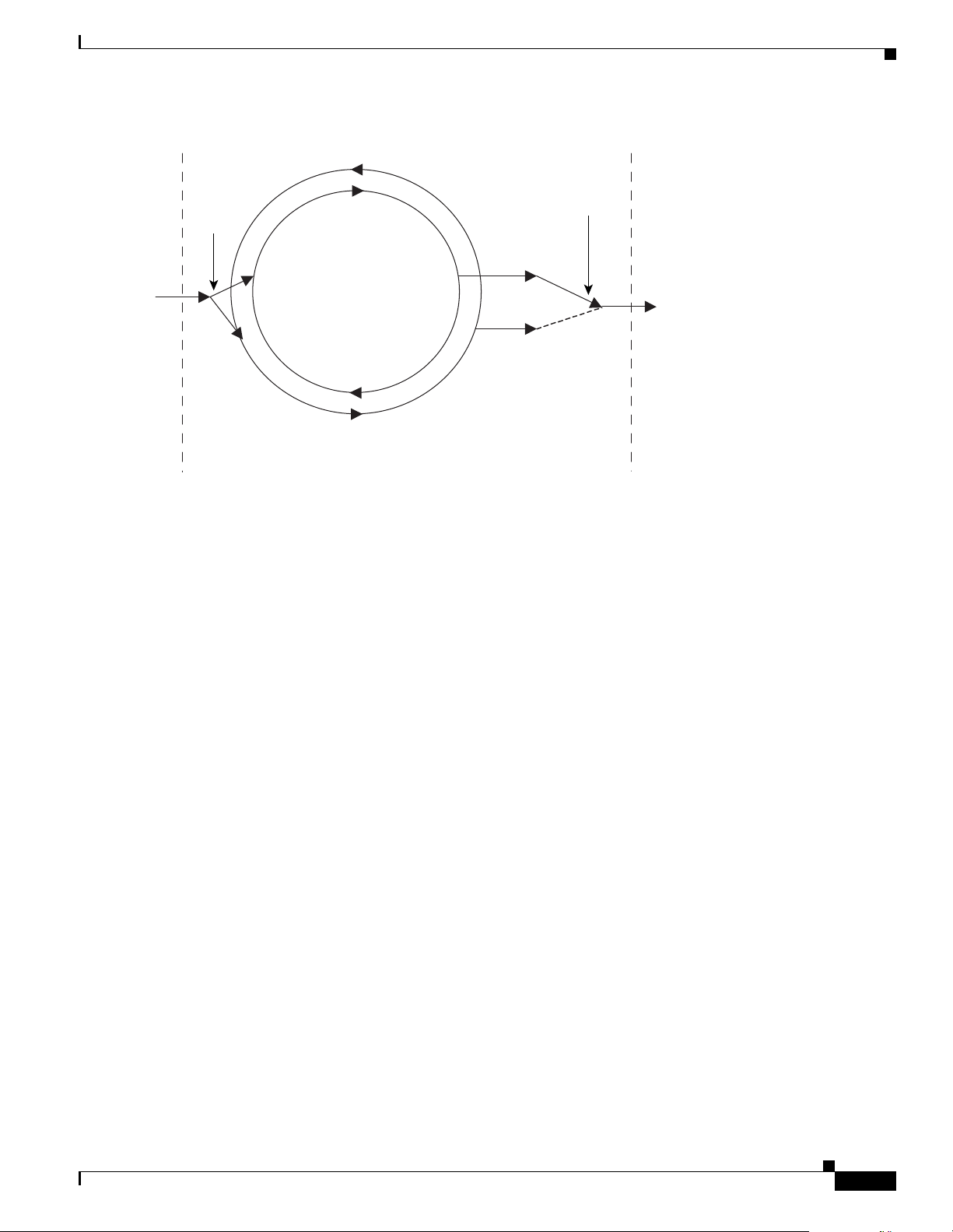
In optically-protected channels, data traffic flows in two physically separated streams to the receiving
node. The conf igura ti on of th e re ce ivi ng nod e de term in es w hi ch t raffic f lo w i s tra nsfe r red t o the cli ent
layer of the re ce ivi ng no de . Figure 1-2 displays an example of optical fiber-prote cted chann els in an
ONS 15200 system. This form of opti cal chan nel prot ection i s rapid and provi des cont inued syst em
coverage in case o f fibe r bre ak s bet we en no de s.
ONS 15200
CLIENT OUT
CLIENT IN
LEGEND
ONS - Optical network system
54647
1-2
Cisco ONS 15200 Product Description
78-13766-01
Page 19
Chapter 1 Product Technology
Figure 1-2 Optically-fiber protected channels in an ONS 15200 system
DIVIDER
CLIENT INPUT
SIGNAL
ONS 15200
OPTICAL
CHANNEL
A
OPTICAL
CHANNEL
B
Optical Channels
SELECTOR
CLIENT OUTPUT
SIGNAL
Client-layer prot ecti on sche mes f or the ON S 1 520 0 are :
• SONET/SDH ADM rings—Traffic travels in two directions bet wee n an y t wo nod es. I f one r oute
fails, the alternate route continues to transport the traffic.
• Client-la ye r 1+ 1 APS —Two separate connections exist between two client -la yer int erfa ces. One o f
the connections is st andb y a nd is use d o nly wh en the ac tiv e conne c tio n fai ls.
• Layer 3 load sharing—Two routes transport traffic f rom o ne c lient to a d ual home no de ( s ee
Chapter 2, “Product Configurations” for a description of the dual home node configur ation ). The
routes are used belo w their maximum capacity. If one of the two routes f ails, th e tra ffic shifts to the
other route.
1.2.3 Software Configurable Protection
In Release 1.1, the 2R/3R (u nclo cked /cl ocke d) Clie nt L ayer I nterfa ce Port (CL IP) m odule is use r
configurable f or unp rot ec ted or fib er pr ote cte d opera ti on.
LEGEND
ONS - Optical network system
54628
78-13766-01
Cisco ONS 15200 Product Description
1-3
Page 20

Optical Channels
Chapter 1 Product Technology
1-4
Cisco ONS 15200 Product Description
78-13766-01
Page 21

Product Configurations
This chapter desc rib es co mm on Cisco ON S 1 520 0 n etwor k c onfi gu ratio ns. Al l mo dule s m ent ione d in
this chapter are described in more detail in Chapter 5, “Module Descriptions.”
2.1 ONS 15200 Network Configurations
The ONS 15200 operates in several network configuration arrangements. All ONS 15200 configurations
consist of one or more ONS 15252 Mult ichannel Un its (MCU) or ONS 15201 Single -Channe l Units
(SCUs). The following inf ormation describe s some standar d ONS 15200 network configura tions,
including:
• The “Bus Confi guration ” sect ion on page 2-1
• The “Ring Conf igurati on” section on page 2-2
• The “Dual-Home Configuration” section o n pag e 2-3
• The “Multichannel Point-to-Point Configuration” section on page 2-3
CHAPTER
2
• The “Ring Configuration with Hubbed and Meshed Traffic” section on page 2-4
• The “Full-Mesh Configuration” section on page 2-5
2.1.1 Bus Configuration
In an ONS 15200 system bus configu ratio n, waveleng th channe ls link an ONS 152 52 MCU to ONS
15201 SCUs. Use this confi guratio n only in networks where opti cal-la yer fibe r protec tion is
unnecessary. It is possible to configure the bus configuration for layer-3 load-sharing protection or client
layer 1+1 APS, but the two data traffic flows would need to share the same optical fiber path, and
therefore protecti on would be incomple te.
In the bus configuration, the Client Layer Interface Port (CLIP) modules located in the ONS 15252 MCU
and in each ONS 15 201 SCU excha nge data. Figure 2 -1 illustrate s the ONS 15200 syste m bus
configuration.
Note The physical connec tion in Figure 2-1 consists of two fiber-optic cables.
78-13766-01
Cisco ONS 15200 Product Description
2-1
Page 22
ONS 15200 Network Configurations
Figure 2-1 An ONS 15200 bus configuration linking an ONS 15252 MCU to eight ONS 15201 SCUs
PHYSICAL
CONNECTION
CLIENT
Client
Chapter 2 Product Configurations
ONS 15252
ONS 15201
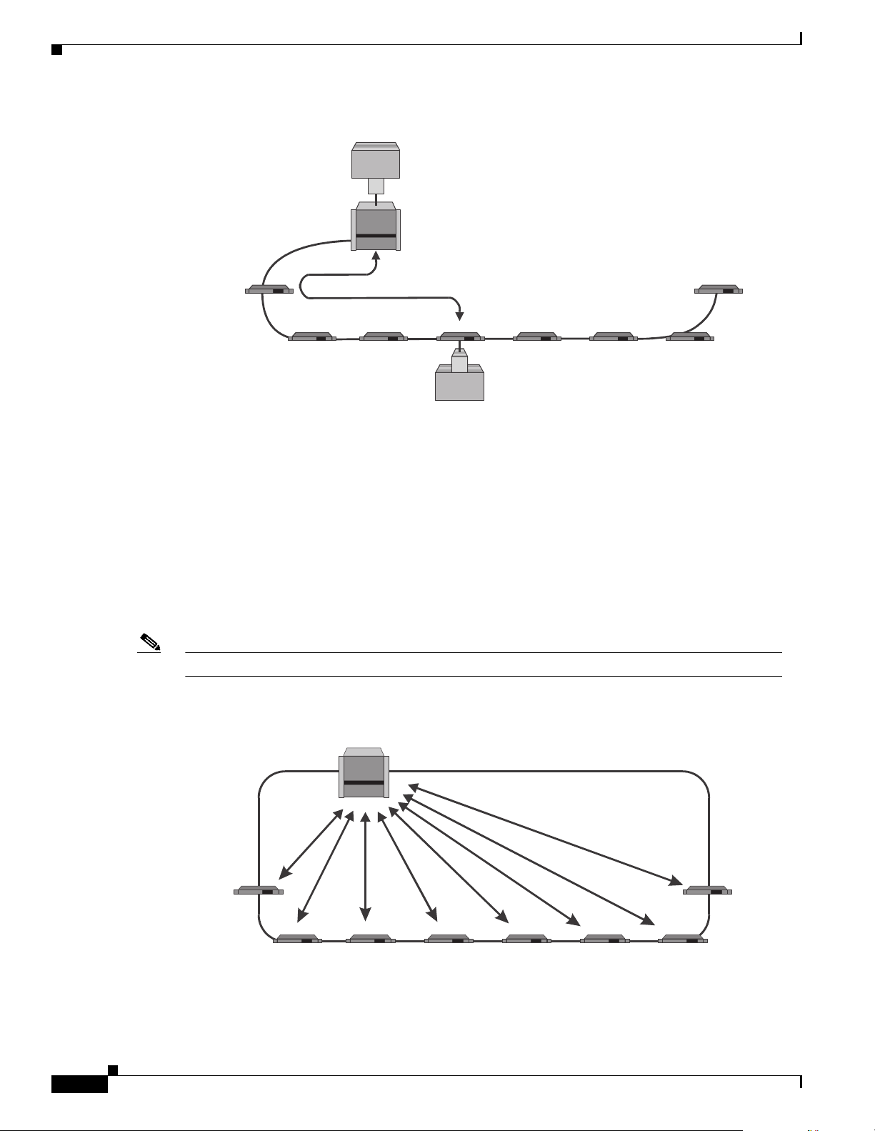
2.1.2 Ring Configuration
In the ONS 1520 0 r ing co nfig ura tion, wa ve leng th c hanne ls e xis t betw ee n an O NS 15252 MCU and
several ONS 15201 SCUs. A CLIP module installed in the O NS 15252 MCU exchanges da ta with an
associated CLIP mo dul e i nsta lled in an ON S 15 201 SCU.
You ca n in stall the ring conf ig urati on with or wi thou t fibe r-optic pro tec tio n. T he ri n g con figur a tion
supports SONET o r SDH ring protection and 1+1 APS cl i ent-layer protectio n.You can also arrange the
ring configuratio n to use layer-3 load sharing. Figu re 2-2 illustrates the ring configuration with hubbed
traffic.
Note The physical connec tion in Figure 2-2 consists of two fiber-optic cables.
ONS 15201
LOGICAL CONNECTION
ONS 15201
ONS 15201 ONS 15201 ONS 15201
CLIENT
Client
LEGEND
ONS - Optical network system
ONS 15201
ONS 15201
54629
2-2
Figure 2-2 Ring configuration with hubbed traffic
PHYSICAL
CONNECTION
ONS 15201
Cisco ONS 15200 Product Description
ONS 15252
ONS 15201ONS 15201
ONS 15201
LOGICAL CONNECTIONS
ONS 15201ONS 15201ONS 15201
LEGEND
ONS - Optical network system
ONS 15201
54630
78-13766-01
Page 23
Chapter 2 Product Configurations
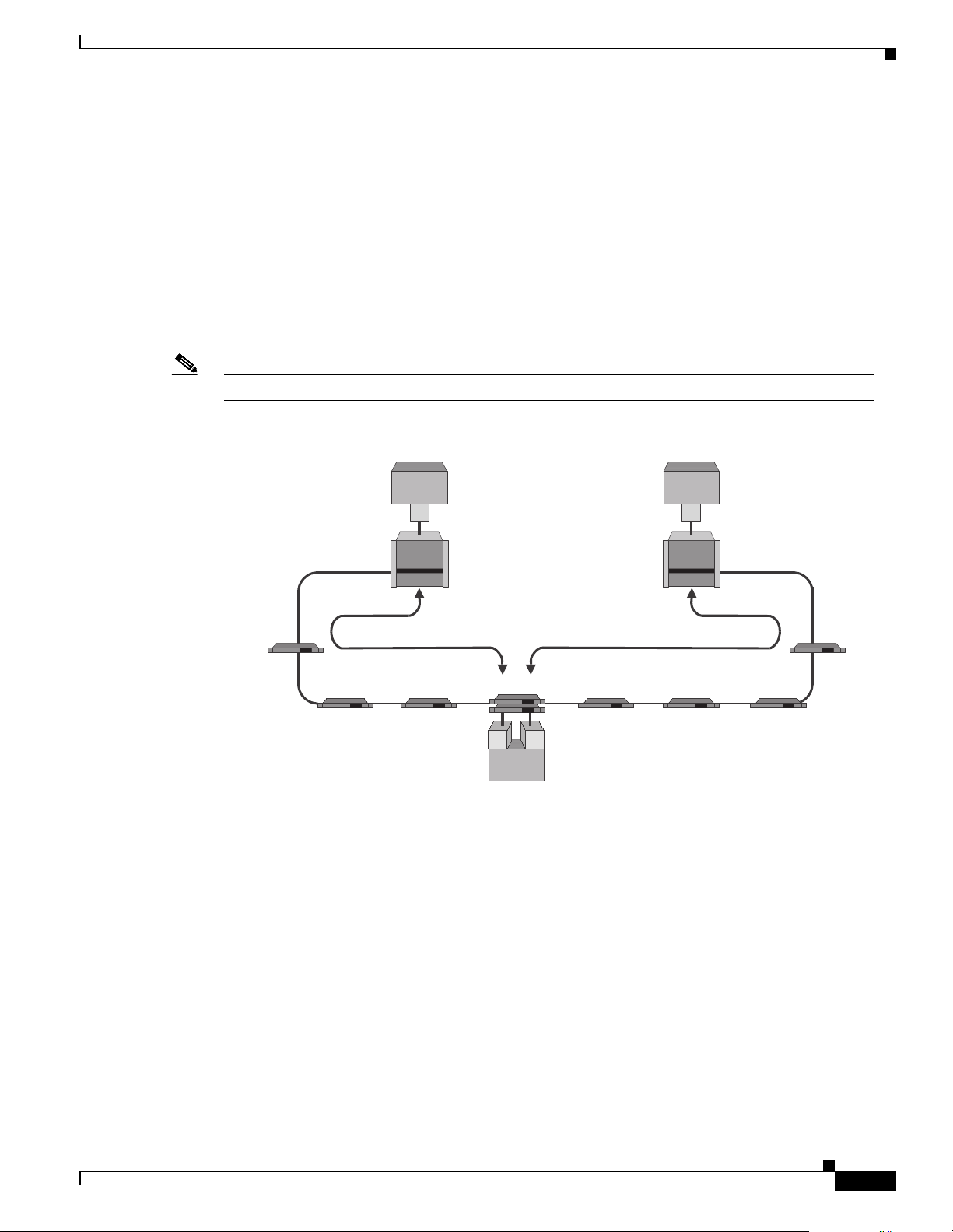
2.1.3 Dual-Home Configuration
In the dual-home configuration, a pair of ONS 15201 SCUs share the total data traffic load between two
different fiber-optic cable (fib er) rou tes. The pai r of ONS 15201 SCUs can use id entic al or different
wavelength channel s to comm unicate with thei r respec tive ON S 15252 MC Us. Usin g ident ical
wavelength channels conserve s network resource s. In addit ion to load sha ring, the dual-hom e
configuration pro vide s tr affic pro tec tio n in the el ect ro nic cli e nt-la ye r dom ain . If one fi ber rou te is lost,
the data traffic shifts to the other fiber route in the client layer.
In addition to protecting traffic at the client layer, the dual-home configuration protects the ONS 15200
system against single MCU or SCU failures. Figure 2-3 illustrates the ONS 15200 dual-home
configuration.
Note The physical connec tion in Figure 2-3 consists of two fiber-optic cables.
Figure 2-3 Dual-home configuration
ONS 15200 Network Configurations
CLIENT
Client
PHYSICAL
CONNECTION
ONS 15252
LOGICAL CONNECTIONS
ONS 15201
ONS 15201(TWO)
ONS 15201
ONS 15201
CLIENT
Client
2.1.4 Multichannel Point-to-Point Configuration
In the ONS 15200 multichannel, point-to-point configuration, multiple wavelength channels exist
between a pair of ONS 15252 MCUs. You can set up the multichan nel point- to-point configur ation wit h
or without optic al-l ay er pro tec ti on. Co nfi g uring op tica l-l ay er prot ect ion r eq uire s d ual fibe r ro utes.
In the ONS 15200 multichannel, point-to-point configurations, dual fiber routes send information along
two separate fiber routes . The dual physical rou te configu ration suppo rts SONET or SD H add/drop
multiplexer (ADM) prote ction and c lient-la yer 1+1 APS prot ection.
Cisco does not r ecom mend impl eme nti ng layer-3 l o ad-sha ring p rote ction i n a mu ltic ha nnel
point-to-point confi guration because the two netwo rk fiber rout es need to share an ONS 15252 MCU,
and any failure of the ONS 15252 MCU would cause both routes to disappear simultaneously . Figure 2-4
illustrates the ONS 15200 multichannel, point-to-point configurations.
ONS 15201
CLIENT
nt
ONS 15252
ONS 15201
LEGEND
ONS - Optical network system
ONS 15201
ONS 15201
54630
78-13766-01
Cisco ONS 15200 Product Description
2-3
Page 24

ONS 15200 Network Configurations
Note The physical connec tion in Figure 2-4 consists of two fiber-optic cables.
Figure 2-4 Multichannel point-to-point configurations, single and dual connections
Chapter 2 Product Configurations
ONS 15252
ONS 15252
SINGLE PHYSICAL CONNECTION
DUAL PHYSICAL CONNECTIONS
LEGEND
ONS - Optical network system
ONS 15252
ONS 15252
2.1.5 Ring Configuration with Hubbed and Meshed Traffic
In the ONS 1520 0 r ing co nfig urat ion with hub be d and m esh ed tra ffic, t wo O NS 1 520 1 SC Us
communicate with each other. You can use either unit in a direct point-to-point configuration throu gh a
control area network (CAN) bus connection as shown in Figure 2-5, or with a noninterfering ONS 15252
MCU. If you u se an O N S 1 5252 MCU , the MCU m ust ha ve a n in st alled Br idge m odu le (BM) .
To manage a mesh configuration, use the Maintenance Manager (MM) software and associated hardware
or use a CAN bus extension cable to connect one of the ONS 15201 SCUs using the meshed channel to
the ONS 15252 MCU. An ONS 15201 SCU connected in this way will be on the same logical CAN bus
as the ONS 1 525 2 MC U.
54632
2-4
In the mesh configuration, you can configure SONET or SDH ADM ring protection on the client side of
the meshed channe l. If yo u us e c lient -la yer 1+ 1 APS pro tec tion, yo u m ust repl ace ea ch of t he
ONS 15201 SCUs with a pair of ONS 15201 SCUs transmitting in opposite d irections. Figure 2-5
illustrates the ONS 15200 ring configur ation with hubbed and meshed t raffic.
Note The physical connec tion in Figure 2-5 consists of two fiber-optic fiber cables.
Cisco ONS 15200 Product Description
78-13766-01
Page 25

Chapter 2 Product Configurations
Figure 2-5 Ring configuration with hubbed and meshed traffic
ONS 15200 Network Configurations
PHYSICAL
CONNECTION
ONS 15201
ONS 15201
ONS 15252
ONS 15201
ONS 15201
2.1.6 Full-Mesh Configuration
In the ONS 1520 0 f ul l-m esh c onf igur ati on , all O NS 1 525 2 MCU s co mm unic ate wi th each o th er.
A single Network Cont ro l Board ( NC B) mo dul e l oca ted in o ne of th e ONS 152 52 MC Us m anage s the
full-mesh confi guration. The NCB modules in the other ONS 15252 MCUs are not used; an NCB front
cover replaces them.
LOGICAL CONNECTIONS
ONS 15201
ONS 15201
LEGEND
ONS - Optical network system
ONS 15201
ONS 15201
54633
In the full-mesh conf igur at ion, you ca n conf igure SONET or SD H A DM ring pr otect ion on the cl ien t
side of the units. Layer-3 load sharing is supported. To implement client-layer 1+1 APS protection, you
must replace each of th e units with a pair of units transmitting in opposite directions of the ring.
Figure 2-6 illustrates the ONS 15200 full-mesh configuration.
Note The physical connec tion in Figure 2-6 consists of two fiber-optic cables.
78-13766-01
Cisco ONS 15200 Product Description
2-5
Page 26

Network Protection
Figure 2-6 Four ONS 15252 MCUs in a full-mesh configuration
ONS 15252
PHYSICAL
CONNECTION
LOGICAL CONNECTIONS
ONS 15252
Chapter 2 Product Configurations
ONS 15252
2.2 Network Protection
Release 1.1 prov id es th e Forward Defect Indication (FDI) switch (f d i _switch), which can be enabled or
disabled. When fdi_s witch is enable d, the FDI alarm ca use s the tra f fic to s witch p aths. A CLIP re cei ves
the FDI alarm if and only if its companion CLIP loses its client- side input signal. The sever ity of the FDI
alarm is mino r.
ONS 15252
LEGEND
ONS - Optical network system
54646
2-6
Cisco ONS 15200 Product Description
78-13766-01
Page 27

Product Hardware
This chapter desc rib es the Cisc o ON S 152 00 me chan i cal c om ponent s. I t a ls o prov id es elec tri cal ,
electromagnet ic, an d safety i nform ation about the ONS 15200 .
3.1 Modularity and Ancillary Equipment
Equipment in the ONS 15200 syst em is modula r in design. Ea ch system function i s carried out by
modules located in eit her an ONS 152 52 MCU or an O NS 1 5201 SCU . Sites i n the ON S 15200 system
consist of eit her an ON S 15 252 M CU, a n ON S 1 520 1 SC U, or a co mb inat ion of the two. ON S 1520 0
site configurations may al so include a power dis tribution pa nel (PDP) .
3.1.1 ONS 15252 MCU
CHAPTER
3
The ONS 15252 MCU com mu nica tes w ith t he ot her nod es in t he O NS 15 200 syst em on one or seve ra l
channels. Each c ha nnel o ccup ies a wav ele ngth, a nd some O NS 15 200 sy stem c onfi gur atio ns reuse a
wavelength. As shown i n Figure 3-1, several channe ls of info rmati on, eac h occup ying a wa veleng th,
enter the node from the DWDM layer. Each channel can enter the ONS 15252 MCU fro m the A side, the
B side, or the A side and B side.
The ONS 15252 M CU c om mun icat es w ith the oth er n ode s in the ON S 1 520 0 syst em on o ne or mor e
wavelengths. Information originates at the ONS 15252 MCU Client Layer Interface Port (CLIP) module.
For optically-protected channels, the Network Adaptation module (NAM) splits the information and
transmits it in opposite directions through two Hub Filter Modules (HFMs) and two Line Modules (LMs)
at a specific wav elengt h.
For unprotected channels, the N AM transmits the in formation to eith er an A-side H FM or a B-side HFM
and then thr ough t h e associ at ed L M. I nf orm ati on car rie d o n a wa vel engt h int end ed f or a nothe r O NS
15200 site passes through the ONS 15252 MCU without interference except for the insertion loss of the
ONS 15252 MCU, if a BM or a CMX is used. If the ONS 15252 M CU is equipped wit h Termination
modules (TMs) inst ead of a B M, t he T Ms b lo ck a ny wav elengt h or c hanne l n ot d rop ped t o t he
ONS 15252 MCU.
78-13766-01
Cisco ONS 15200 Product Description
3-1
Page 28

Modularity and Ancillary Equipment
Figure 3-1 Functional view of the ONS 15252 Multichannel Unit (protected version)
To and from the client layer
(External to the ONS 15200 system)
Tx
AB
CLIP
Chapter 3 Product Hardware
To and from
the DWDM layer
A-side
optical
OUT
IN
LM HFM BM HFM LM
NAM
LEGEND
A - A side
B - B side
BM - Bridge Module
CLIP - Client Line Interface Port module
DWDM - dense wavelength division multiplexing
HFM - Hub Filter Module
LM - Line Module
NAM - Network Adaptation Module
B-side
optical
OUT
IN
To and from
the DWDM layer
54635
Two versions of the ONS 15252 M CU mec hani cal she lf exi st: Rel eas e 1.0 a nd Relea se 1.0. 1. Cisc o
currently ships only the Relea se 1.0.1 shel f and no longe r ships the Rel ease 1.0 shelf.
Release 1.0.1 and later shelve s inc l udes a baffle. The baffle is a partial ly- p er fo r ated , ang led metal plate
that is mounted below and behind the metal support beam and is mechanically attached to the back of
the shelf. It runs the width of the shelf. To view the baffle, look up through the ventilation cavities at the
back of the shelf. Fi gure 3-2 illustrates a shelf with a baf ffe (Release 1.0.1), and a shelf without a baffle
(Release 1.0).
Figure 3-2 Release 1.0.1 (and later) shelf baffle compared to the Release 1.0 shelf without baffle
3-2
Baffle
Cisco ONS 15200 Product Description
78-13766-01
Page 29

Chapter 3 Product Hardware
ONS 15252 Releases 1.0.1 and lat er include a fa n unit. Befor e using the Rele ase 1.0.1 shelf, you must
install the fan unit. Do not use the fan unit with a Release 1.0 shelf. See the “Fan Unit” section on
page 3-4 for more in format ion about the fan unit .
Caution You must install the fan unit in a Release 1.0.1 shelf. Running the Release 1.0.1 shelf without the fan
unit will result in a unit that is not compliant to any specifications, nor is warranted or supported by
Cisco. In addition, such usage ma y result in eq uipmen t damage .
Caution Do not install the fan unit in a Release 1.0 shelf. Running the Release 1.0 shelf with a fan unit will
result in a unit that is not compliant to any specifications, nor is warranted or supported by Cisco. In
addition, such usage may resu lt in equi pment dama ge.
ONS 15252 Releases 1.0.1and l ater inclu de an updat ed Netwo rk Adaptati on modu le (NAM). Th e
Release 1.0.1 NA M ha s a “NEBS-3 compliant” label on the faceplate, whereas the previous version of
the NAM does not have a faceplate label. The Release 1.0.1 shelf requires the Release 1.0.1 NAM. You
can also use Release 1.0.1 NAMs in the Release 1.0 shelf. See the Cisco ONS 15200 Module Handbook
for more informati on about t he NAM.
Modularity and Ancillary Equipment
Caution Placing NAMs without the “NEBS-3 compliant” label into an Release 1.0.1 shelf may result in
equipment damage .
3.1.2 ONS 15201 SCU
The ONS 15201 SCU communicates with the othe r nodes in the ONS 152 00 system on a spe cific
wavelength or channel. T he SCU use s a single CLIP mo dule . From th e DWD M lay er, several chan nels
of information, eac h occup ying a wav elength , enter t he ONS 15201 SCU. Each D WDM cha nnel of
information can enter the ONS 152 01 SCU from the A side, the B side, or the A side and B side .
The Collector Filter module (CFM) drops and transfers the specific channel or wavelength intended for
the ONS 15201 SCU to the CLIP module. For protected channels, the CFM drops the chann el from the
A side and B side. For unprotected channels, the CFM drops the channel from either the A side or B side.
The CLIP transfers information originating at the ONS 15201 to the CFM for protected channels. The
CFM splits the information and transmits it at a specific wavele ngth or channel in op posite direction s on
the A side and B side. The CFM does not split unprotected channels; it transmi ts the m directly to ei ther
the A side or B side. Information carried on a wave length or channel inte nded for ano ther ONS 15200
node passes through the ONS 15201 SCU without inte rferenc e except for the insert ion loss cause d by
the unit. Figure 3-3 shows a functional repr esenta tion of an ONS 15201 SCU.
78-13766-01
Cisco ONS 15200 Product Description
3-3
Page 30

Modularity and Ancillary Equipment
Figure 3-3 A functional view of the ONS 15201 SCU
TO AND FROM THE CLIENT LAYER
(EXTERNAL TO THE ONS 15200 SYSTEM)
Tx
Chapter 3 Product Hardware
A-SIDE
OPTICAL
TO AND FROM
THE DWDM LAYER
IN
OUT
3.1.3 Power Distribution Panel
ONS 15200 site configurations can include a power distribution panel (PDP). The PDP distributes power
to the ONS 15200 site and provides power redundancy. It uses input and output fusing to provide system
protection.
3.1.4 Fan Unit
A
B
CLIP
CFM
LEGEND
A - A side
B - B side
CFM - Collector Filter Module
DWDM - dense wavelength division multiplexing
B-SIDE
OPTICAL
TO AND FROM
OUT
THE DWDM LAYER
IN
54636
3-4
All Release 1. 0.1 ( or lat er) ON S 1 5252 M CU s it e c on figur ati on s r equi re a f an u ni t m ounte d ab ove t h e
ONS 15252 M CU i n t he e quipm e nt r ack; R el eas e 1.0 sh elves do not use the fan u nit . The fan u nit
contains eight small fans that run simultaneously at constant speed. The fans push air down through the
MCU to cool the C LI P m odu les. T he fan un it is powe red by it s o wn du al -48 V DC pow er in lets
independently of the MCU. If the fan unit fails, it generates an alarm to indicate multi- or single-fan
failure. Located on the front panel of the fan unit are three LEDs to indicate alarm status. Table 3-1 lists
the LED status and cause of alarm.
Table 3-1 Fan Unit LED Status
LED Status Cause
Red Major a lar m Multi-fan fa il u re
Yellow Minor alarm Single-fan failure and/or single
48 VDC failure
Green Normal Power on
Cisco ONS 15200 Product Description
78-13766-01
Page 31

Chapter 3 Product Hardware
Caution You must install the fan unit in a Release 1.0.1 shelf. Running the Release 1.0.1 shelf without the fan
unit will result in a unit that is not compliant to any specifications, nor is warranted or supported by
Cisco. In addition, such usage ma y result in eq uipmen t damage .
Caution Do not install the fan unit in a Release 1.0 shelf. Running the Release 1.0 shelf with a fan unit will
result in a unit that is not compliant to any specifications, nor is warranted or supported by Cisco. In
addition, such usage may resu lt in equi pment dama ge.
3.1.5 Fiber Organizer
The fiber organizer d istr ibut es t he cl ien t fi ber-opt ic cabl es to the ON S 1 525 2 M CU CLI P m odu les.
Additionally, the fiber organizer provides tensi on relief fo r the clie nt fiber-optic cables. You can also
install a fiber organizer between additional ONS 15252 MCUs or ONS 15201 SCUs located at a site. A
fiber organizer is always includ ed wit h an ONS 15252 M CU.
You ca n p lac e t he f i ber o rganize r on t he fan un it front . T hi s p lacem en t do es no t int erfe re wit h fan unit
filter replacement.
Physical Layout
3.2 Physical Layout
This section describes the phy sical con figurati on of the ONS 152 52 MCU and O NS 15201 SCU.
3.2.1 ONS 15252 MCU Physical Configuration
The ONS 15252 M CU physi cal confi gu ratio n con s ists of a Ne two rk Co ntrol Boa rd (N CB ) modu le,
Network Adaptati on mod ul es (N AM s), a C omm unica tio n I nterfa c e mo dule ( CIM), Cli ent La yer
Interface Port (CLIP) mod ules, Hu b Filter m odules (HFM s), a pair of L ine m odules ( LMs) , an d one
Bridge module (BM ) (see Figur e 3-4). A pair of Termination modules (TMs) replace the BM when all
optical signal c hanne ls or wa vel engt hs are dr opp ed at the ON S 15252 MCU. Add ition al ly, when
multiple ONS 15252 MCU s are i nterconne cted , Connec tion Mo dule X (CM X) and/ or Connect ion
Module Y (CMY) repl ace the BM . The ty pe of con ne ction mo dule u sed depe nd s o n the spe cific ON S
15200 system configurat ion.
78-13766-01
Cisco ONS 15200 Product Description
3-5
Page 32

Physical Layout
Chapter 3 Product Hardware
Figure 3-4 Configuration of the ONS 15252 Multichannel Unit
NCB - Network Controller Board
CLIP - Client Line Interface Port
NAM - Network Adaptation Module
CIM - Communications Interface Module
LM - Line Module
HFM - Hub Filter Module
DFM - Dummy Filter Module
BM - Bridge Module
A - Side
B - Side
54637
The lower portion of the ONS 15252 MCU is referred to as the passive optical shelf. The passive optical
shelf has an A side and B side. T he A side of the O NS 15252 MC U is lo ca ted on t he l eft s ide of t he
passive optical shelf, as see n from the fr ont. The A-side LM con tains on e line IN port (FC), one line
OUT port (FC), and two line-monitoring ports (SC). The line-monitoring ports make it possible to
monitor the A-side incomi ng and outg oing DWD M optical si gnals.
The B side of the ONS 15252 MCU is located on the right side of the passive optical shelf, as seen from
the front. The B -side LM cont ai ns o ne l ine I N port ( FC), o ne li ne O UT port ( FC), and two
line-monitoring ports (SC). The lin e-monitoring ports make it possible to monitor the B-side incoming
and outgoing DWDM optic al signa ls. The pas sive optic al shelf also co ntain s the A-side and B-side
HFMs and TMs, BMs, CMXs, or CM Ys in variou s combina tions. Figur e 3-5 shows the typical
arrangement of t he m odu l es.
3-6
Cisco ONS 15200 Product Description
78-13766-01
Page 33

Chapter 3 Product Hardware
Figure 3-5 Typical arrangement of the ONS 15252 MCU modules
Physical Layout
INTERNAL - BUS
LM HFM HFM BM HFM HFM LM
CLIP CLIP NCB
NAMNAM
LEGEND
BM - Bridge Module
CLIP - Client Line Interface Port module
HFM - Hub Filter Module
LM - Line Module
NAM - Network Adaptation Module
NCB - Network Control Board module
54638
3.2.2 ONS 15201 SCU Physical Configuration
The ONS 15201 SCU physical configuration consists of a CLIP module and a CFM (Figure 3-6). The A
side of the ONS 15201 SCU is the two far-left opt ical line conne ctors on the fr ont or back of the ONS
15201 SCU. The B side of the ONS 15201 SCU is the two far-righ t optic al li ne conn ec tors on the fron t
or back of the ONS 15201 SCU. The ON S 15201 SCU is norma lly deli vered wi th optica l connect ions
on the front (SC type). O ptio nal ly, you can order the ONS 1 5201 SC U wi th the o pti cal c on necti ons on
the back of the unit (FC type). Back placement is optional for SC connectors.
Note You can order the ONS 15201 SCU with o ptical connectors located on either the front o r th e ba ck of
the unit but not on both the front and back .
78-13766-01
Cisco ONS 15200 Product Description
3-7
Page 34

Power and Grounding
Figure 3-6 Physical layout of the ONS 15201 SCU
CLIENT SIDE
CLIP MODULE
MA INTERFACE
Chapter 3 Product Hardware
PS 1
GND
CFM MODULE
(LOCATED UNDER COVER)
PS 2BA
2
3.3 Power and Grounding
This section desc ribes pow er and g roundi ng for the ON S 15 200 sy stem and inc lude s the “ONS 15252
MCU Power and Gr oun ding ” section on page 3-9 an d the “ONS 15201 SCU Powe r and Gro und ing”
section on page 3-10. The grounding connections for the ONS 15201 SCU and the ONS 15252 MCU are
shown in Figure 3-7.
1
LEGEND
CFM - Collector Filter Module
CLIP - Client Line Interface Port module
MA - Management access
PS 1 - Power Supply One
PS 2 - Power Supply Two
3
54639
3-8
Cisco ONS 15200 Product Description
78-13766-01
Page 35

Chapter 3 Product Hardware
Figure 3-7 ONS 15201 SCU and ONS 15252 MCU grounding
ONS 15201
Power and Grounding
ONS 15252
PS-1
PS-2
PS-1
PS-2
(LOCATED UNDER
FRONT COVER)
3.3.1 ONS 15252 MCU Power and Grounding
Two power supply connectors are located on the backplane of the ONS 15252 MCU. The far-right power
connector (as viewed from the rear of the ONS 15252 MCU) is called PS-1 (power supply one), and the
far-left power connec tor is called PS 2 (p ower supply two), as sho wn in Figure 3-7. The equiva lent PS-1
and PS-2 power supply connector terminals are designated 0V and -48V. Grounding for the ONS 15252
MCU chassis is pro vide d b y two l ug-t ype g rou nding co nnec tor s ( Figure 3-7).
LEGEND
ONS - Optical network system
PS-1 - Power supply one
PS-2 - Power supply two
54640
78-13766-01
Note To prevent ground loops, use only o ne groun di ng c onnec tor.
Cisco ONS 15200 Product Description
3-9
Page 36

Environmental Compliance
3.3.2 ONS 15252 Fan Unit Power and Grounding
The fan unit back panel has two po wer supply connect ors. The far-right power con nector (as viewed
from the rear of t he fan un it) is th e prim ar y sour ce , a nd the fa r-left p ow er c on ne ctor is th e se co ndary
source. These power conne ctors ar e designat ed as 0V and -4 8V. A pair of groundi ng pins (M4 sc rews)
is located next to each of the power connectors on the fan-unit back panel.
3.3.3 ONS 15201 SCU Power and Grounding
The ONS 15201 SCU chassis ha s two po wer supply conn ec tor s. Th e po wer supply loc a ted on the fr ont
of the ONS 1520 1 SCU chas sis is l abe led PS-2 ( pow er supp ly tw o) , and the powe r suppl y conn ect or
located on the ba ckpl ane of t he ON S 1520 1 SCU cha ssis i s labeled PS- 1 (pow er supp ly o ne)
(Figure 3-6). Lug-type grounding connectors located on the back of the chassis provide grounding. The
power supplies convert AC to DC and provide a regula ted -48 VDC t o the ONS 15201 SCU .
3.4 Environmental Compliance
Chapter 3 Product Hardware
The ONS 15252 MCU is compliant with Network Element Building Systems (NEBS) Level 3 of
Telcordia SR-3580 and applicable section s of Telcordia GR-63-CORE and Telcordia GR-1089-CORE.
Additionally, the ONS 15200 system is compliant with ETS 300 019-1-1 (c lass 1.1), ETS 300 019-1-2
(class 2.3), and E TS 300 01 9- 1-3 (cla ss 3. 1) f or en viro nment al requ ire ment s.
The ONS SCU 15201 is compliant with Network Element Building Systems (NEBS) Level 2 of
Telcordia SR-3580 and applicable section s of Telcordia GR-63-CORE and Telcordia GR-1089-CORE.
Additionally, the ONS 15200 system is compliant with ETS 300 019-1-1 (c lass 1.1), ETS 300 019-1-2
(class 2.3), and E TS 300 01 9- 1-3 (cla ss 3. 1) f or en viro nment al requ ire ment s.
3.5 Electromagnetic Compatibility
The ONS 15200 system is compliant with Telcordia GR-1089-CORE and FCC Part 15 specifications for
electromagnetic compatibility for NEBS Level 2 (SCU) and Level 3 (MCU). Additionally, the ONS
15200 system is complaint with E TS 300 386-1, cla sses 1 and 2 for electromag netic com patibilit y.
3.6 Safety Specifications
This section provides ONS 15200 syste m laser and pro duct safety spe cificatio ns.
3.6.1 Laser Safety
3-10
The ONS 15200 system is compliant with IEC-608 25-1, IE C 60825-2 , and CFR 1040.10 require ments
for laser safety.
Cisco ONS 15200 Product Description
78-13766-01
Page 37

Chapter 3 Product Hardware
3.6.2 Product Safety
The ONS 15200 system equipm ent comp lies wit h the produ ct safet y requir ement s in Europea n Norm
(EN) 60 950 and Underwrite rs Labor atory (UL ) 1950. Th e equipm ent also adheres to the Europ ean
Union (EU) low vo ltag e d irect ive LVD 73/23/ECC.
3.7 Wavelength Grid
The ONS 15200 system adhere s to 200 GHz wavel ength spacing an d the wav elength spec ificat ions
defined in ITU-T G.692 . Table 3-2 shows the wavelength plan.
Table 3-2 ONS 15200 Wavelength Plan
Channel Number Frequency (THz) Wavelength (nm)
23 192.3 1558.98
25 192.5 1557.36
Wavelength Grid
27 192.7 1555.75
29 192.9 1554.13
31 193.1 1552.52
33 193.3 1550.92
35 193.5 1549.32
37 193.7 1547.72
43 194.3 1542.94
45 194.5 1541.35
47 194.7 1539.77
49 194.9 1538.19
51 195.1 1536.61
53 195.3 1535.04
55 195.5 1533.47
57 195.7 1531.90
78-13766-01
Cisco ONS 15200 Product Description
3-11
Page 38

Wavelength Grid
Chapter 3 Product Hardware
3-12
Cisco ONS 15200 Product Description
78-13766-01
Page 39

Operation, Administration, and Maintenance
This chapter desc rib es t he c omp onent s requi red fo r ope ra tion, a dmin istrat ion , and m a inten ance o f th e
Cisco ONS 15200.
4.1 Network Control
The Network Control Board (NCB) supervise s, admi nisters, a nd monitors t he ONS 15200 . In addi tion
to controlling all of the ONS 15200 system Client Layer Interface Port (CLIP) modules, the NCB module
collects information about system status, alarms, parameters, and actions on the internal data bus. See
the “Alarms” section on page 4-9 for a description of NCB alarms.
4.2 Network Management Overview
CHAPTER
4
You ca n m ana ge a n O NS 1520 0 netw ork using t hree d ifferen t c onn ect ion int erfa ces:
• An Ethernet connection to the NCB module located in an ONS 15252 Multichannel Unit (MCU).
• A Maintenance Man ager so ftwar e c onnec tio n o ver the int erna l da ta bu s t o t he Co mm unic ation
Interface Module (C IM) l oca ted in an O NS 1525 2 M CU or t o the Coll ect or Con t rol A rea Netw or k
(CCAN) board lo cat ed i n a n O NS 1 520 1 Sin gl e-Cha nn el Unit (SCU ).
• An Electronic Industries Association/Telecommunication Industry Association (EIA/TIA)
EIA/TIA-232 (RS-23 2) port connec tion loc ated on the CIM in the ONS 152 52 MCU. Thi s
connection meth od re quir es the EIA /TI A-23 2 c abl e i nclu ded with t he O NS 15252 M CU .
Figure 4-1 illustrates the three network management interface connections.
You ca n con trol the ONS 15200 syst em using the Su bnet work M anag er ( SNM) sof twar e pack ag e
running on the NCB m odu le loca ted in the ON S 15 252 MCU . Acce ss the SNM throu gh eithe r the
EIA/TIA-232 po rt o r th e Et her net por t on t he fro nt o f th e NCB m od ul e. A dd ition al ly, you can ma nage
the ONS 15200 system exte rnall y usi ng the Comm and Li ne Int erfa ce (CL I) sof twar e pack age de scr ibed
in the “Command Line Interface” section on page 4-5 or using the Maintenance Manager (MM) software
package describe d in the “Maintenance Ma nager” section on page 4-6. Wi th th e Inte rn et, you ca n vie w
the ONS 15200 system using the web-based interface described in the “Web-Based Interface” section on
page 4-7. In additio n, you can use SNMP an d the Cisco Transport Mana ger (CTM ) to have read -onl y
access to the ONS 15200.
78-13766-01
Cisco ONS 15200 Product Description
4-1
Page 40

Network Management Overview
An internal da ta bus, a lso ca lled a c ontr ol ler are a ne two rk (CAN ) bu s, co nnec ts an N C B m odule to
different CLIP modules of the ONS 15252 MCU. You can extend this data bus over several co-located
network elements (ONS 1525 2 MCUs or ONS 152 01 SCUs) to a larger logic al unit. The O NS 15 201
SCU uses the same d ata b us as t he M CU . N orm ally one CA N bus c onn ect s al l O NS 15 200 e quip ment
located at one site.
An overhead cha nnel ex is ts and is imp lem en ted as a ba se b an d modu l ation on the ind i vidua l D WDM
optical channels. T wo end-points of a channel communicate using this low frequency signal, called QPP
(Qeyton Proprietar y Pr otoc ol). The QPP spe cifica tio n def ine s the physi cal an d lin k la yer pro toco ls f or
communication .
Any CLIP module co ntrolled by an NCB mu st not be more than two QPP hops away from that NCB. If
the CLIP is further away from the NCB, you must install additional NCB modules.
Release 1.1 allows you to co nfigure up to two activ e NCBs as mana gers of any CLI P in a network . To
manage the CLIP, it must be no further than two CAN and two QPP hops away from the NCB. Any NCB
in a network that is not provisioned as an active manager of a CLIP can still inventory the CLIP.
Chapter 4 Operation, Administration, and Maintenance
4-2
Cisco ONS 15200 Product Description
78-13766-01
Page 41

Chapter 4 Operation, Administration, and Maintenance
Figure 4-1 An ONS 15200 network management implementation
(read only)
CLI
EIA/TIA-232 (RS-232) Interface
SNMP/CTM
CLI
(TELNET)
EIA/TIA-232
NCB
ETHERNET
INTERNAL
DATA BU S
SNM
CLIP
NEC
ONS 15252
QPP
CLIP
NEC
ONS 15201
INTERNAL
DATA BU S
LEGEND
SOFTWARE APPLICATIONS
CLI - Client Line Interface
MM - Maintenance Manager
NEC - Network Equipment Controller
SNM - Sub-Network Manager
SNMP - Simple Network Management Protocol
CTM - Cisco Transport Manager
WB - Web browser
IP
(HTTP)
WB
MM PC
MM PC
ADDITIONAL ABBREVIATIONS
CAN - Control Area Network
EIA - Electronic Industry Association
HTTP - Hypertext transport protocol
QPP - Qeyton Properietary Protocol
TIA - Telecommunication Industry Association
HARDWARE PLATFORMS
NCB - Network Control Board module
CLIP - Client Line Interface Port module
PC - Personal computer
4.3 EIA/TIA-232 (RS-232) Interface
The EIA/TIA-2 32 por t , lo cat ed a t t he O NS 15252 MCU ma nage ment ac cess (M A) i nte rfac e conn ec tor
on the CIM, provide s a ccess t o t he SN M so ftw are runni ng on t he N CB modu le.
78-13766-01
54641
Cisco ONS 15200 Product Description
4-3
Page 42

EIA/TIA-232 (RS-232) Interface
Y ou o nly need the EIA/TIA-23 2 interface when you are se tting the initial IP address o f the NCB module.
Two pins of the MA interface host the EIA/TIA-232 port; therefore, access the EIA/TIA-232 using the
EIA/TIA-232 cable that is include d with the ON S 15252 MCU. A fter you have set the IP add ress, you
can communicate with t he NCB modul e throug h the Ethern et port loc ated on the front of the NCB.
Figure 4-2 on pa ge 4-5 illustrates EIA/TIA-232 interface access and Ethernet access to the ONS 15252
MCU.
After you have assi gned an I P addr es s to t he N CB mo dul e, you can also se nd inf orm atio n to the NCB
module by file transfer protocol (FTP). Set the EIA/TIA-232 interface to the parameters listed in
Table 4-1. Set the terminal settings to ASCII (send line end with line feed).
Table 4-1 EIA/TIA-232 interface parameter
Parameter Value
Speed 19.2 Kbps
Data Bits 8
Parity None
Stop Bits 1
Flow Control None
Chapter 4 Operation, Administration, and Maintenance
4-4
Cisco ONS 15200 Product Description
78-13766-01
Page 43

Chapter 4 Operation, Administration, and Maintenance
Figure 4-2 ONS 15252 MCU management access
Command Line Interface
Ethernet interface
4.4 Command Line Interface
The SNM software package Command Line Interface (CLI) is a simple, interactive tool that manages
the ONS 15200 sy stem.
Management Access (MA)
interface for EIA/TIA-232
or internal data bus
(depending on cable used)
LEGEND
EIA - Electronic Industry Association
TIA - Telecommunication Industry Association
54642
78-13766-01
Cisco ONS 15200 Product Description
4-5
Page 44

Maintenance Manager
The CLI interf ace r esid es on the NCB mo dule and op er ate s o n th e data base serv er f or t he O NS 15200
system. The CLI interface has two modes of access for users—read-and-write access and read-only
access. Users are separated into three categories: administrator, operator, and guest. Each category has
different privileges:
• Administrator—read-and-write access to security management data
• Operator—read-and-write access to ne tw ork m an agem ent dat a
• Guest—read-only access to network ma nagement data
To access the CLI interface, use the Eth er net port on the NCB m odul e or the MA int erfa ce o n the C IM
module. MA interface access requires a EIA/TIA-232 cable.
4.5 Maintenance Manager
The Maintenance Manager (MM) interactive software tool, installed on a laptop or PC, provides a local
craft interface for the ONS 15200 system. The MM software provides access to the internal data bus at
ONS 15252 MCUs or ONS 15201 SCUs. It also facilitates access to data from isolated ONS 15201 SCUs
in the ONS 15200 network.
Chapter 4 Operation, Administration, and Maintenance
In addition to th e requi red c ablin g, a l apt op mu st have a c on troll er a rea n etwor k ( CAN ) Per sona l
Computer Memory Card International Association (PCMCIA) board to use the MM software package
as a local craft interface.
Connect your MM-equippe d computer t o the ONS 15200 syst em throu gh the MA port as show n in the
following figures. Figure 4-2 on page 4-5 shows the manageme nt access c onnection to an ONS 15252
MCU. Figure 4-3 shows the management access connection to an ONS 15201 SCU.
Figure 4-3 ONS 15201 SCU management access interface
4-6
Cisco ONS 15200 Product Description
MA interface
LEGEND
MA - Management access
78-13766-01
54643
Page 45

Chapter 4 Operation, Administration, and Maintenance
4.6 Web-Based Interface
The web-based interface al l ows read-and-write access to the ONS 15200 system data from any valid IP
address. The NCB mo dul e m ust h av e a defin ed IP addre ss and you mu st l og i nto the SNM soft ware
package running on t he N CB m odu le befor e acc essin g th e web- ba sed i nte rfac e .
Note The web-based interface does not function with Internet Explorer 4.0 or 5.0, Netscape Communicator
6.x, or Opera.
4.7 Internal Data Bus
The controller area network (CAN) bus is a serial communications protocol interface bus that allows you
to connect several ONS 15200 systems to create a more powerful network element. The CAN bus
supports distributed real-time, secure co ntrol. Figure 4-4 shows the t wo data bus extension ports on the
ONS 15252 MCU. Figure 4-5 show s the two da ta bus e xten sion por ts l ocate d on the ON S 1 5201 SCU.
Web-Based Interface
78-13766-01
Cisco ONS 15200 Product Description
4-7
Page 46

Internal Data Bus
Chapter 4 Operation, Administration, and Maintenance
Figure 4-4 ONS 15252 MCU internal data bus extension ports
B
L
A
H
B
L
A
B
L
A
L
L
B
L
A
H
B
L
A
B
L
A
L
B
L
L
A
A
A
H
L
B
A
L
B
A
L
B
B
L
A
H
B
L
A
B
L
A
B
L
L
L
A
A
H
A
L
B
A
L
A
B
B
L
A
L
A
B
L
A
H
B
L
A
B
L
A
L
L
A
B
A
L
L
A
A
H
B
B
L
L
A
A
L
B
A
L
A
L
L
A
A
L
A
B
L
A
L
A
L
A
L
L
A
A
L
A
B
L
A
L
A
A
L
L
A
A
L
L
A
A
L
A
B
L
A
L
A
A
A
L
A
B
L
A
L
A
6-POLE INTERNAL DATA BUS
EXTENSION PORTS
54644
4-8
Cisco ONS 15200 Product Description
78-13766-01
Page 47

Chapter 4 Operation, Administration, and Maintenance
Figure 4-5 ONS 15201 SCU internal data bus extension ports
Simple Network Management Protocol Interface
6-POLE
INTERNAL
DATA BUS
EXTENSION
PORTS
54645
4.8 Simple Network Management Protocol Interface
The simple network management protocol (SNMP) interface allows read-only access to the ONS 15200
system data. For SNMP acce ss, the N CB modul e m ust h ave an assi gned IP addre ss and a valid
community name. The SNMP interface supports simple network management protocol versions 1and 2c.
4.9 Cisco Transport Manager
The Cisco Transport Manager (CTM) al lows re ad-on ly access to the ONS 1 5200 syst em data. CT M
Release 3.1 supports ONS 15200 Re lease 1.1.
4.10 Alarms
In the ONS 15200 web-based int er face, t he Alarms screen shows all th e activ e alarms recorde d for eac h
module installed in the network. Table 4-2 describes the CLIP module alarms, Table 4-3 describes alarm
status parameters, a nd Table 4-4 defines the on-screen colors displ ayed next to the alarm statu s.
78-13766-01
Cisco ONS 15200 Product Description
4-9
Page 48

Alarms
Chapter 4 Operation, Administration, and Maintenance
Table 4-2 Environment Parameter Definitions for Protected Channels
Condition Name Definition
DWDM_R XPO W E R
(unprotected only )
DWDM_ARXPOWER The power input from the A-side of th e ONS 15200 network is
DWDM_BRXPOWER The pow er input fro m the B-s ide of the ONS 1520 0 networ k is
DWDM_PELTIERCURRENT The Peltier current of the selected CLIP module is outside the
DWDM_LASERTEMP The temperature of the laser transmitting to the ONS 15200 network
CLIENT_RXPOWER The power input from the client equipment is outside the acceptable
CLIENT_LASERTEMP The temperature of the laser transmitting to the client equipment is
ENVIRON_BOARDTEMP The temperature on th e s urf ace of the CLIP module circuit board is
The power input from the A-si de of the ONS 15 200 network is
outside the acce pta ble p ower r an ge.
outside the acce pta ble p ower r an ge.
outside the acce pta ble p ower r an ge.
acceptable po wer r ang e.
is outside the acceptable temperature range.
power range.
outside the acce pta ble te mpera tur e range .
outside the acce pta ble te mpera tur e range .
Table 4-3 Alarm Status Parameters
Alarm Name Definition
QPP (unprotec ted
Proprietary protoc ol e rror on the A- side of the n etw or k
only)
QPPA Proprietary protoc ol e rror on the A- side of the n etw or k
QPPB Proprietary protocol er ror on the B -side of the ne twork
CAN Error on the CAN bus
POWER1 PS- 1 input is outsid e of the accept able rang e
POWER2 PS- 2 input is outsid e of the accept able rang e
FDI Loss of channel
Miscellaneous alarms
DAC D/A converter alarm
FLASH EEPROM alarm
INSTRUCTION Software attempted to write to an invalid location (autoclears
after two seconds)
STATUS Alarm indicator
4-10
Cisco ONS 15200 Product Description
78-13766-01
Page 49

Chapter 4 Operation, Administration, and Maintenance
Table 4-4 LED Status Color Definitions (Visible on NAM Front)
Alarm Name Definition
Red Critical or major alarm
Amber Minor alarm or wa rnin g
Green Pow er on
Alarms
78-13766-01
Cisco ONS 15200 Product Description
4-11
Page 50

Alarms
Chapter 4 Operation, Administration, and Maintenance
4-12
Cisco ONS 15200 Product Description
78-13766-01
Page 51

Module Descriptions
This chapter prov ides desc ript ions and spe cif icatio ns for t he C isco O NS 15 200 m odu les, som e times
referred to as a card or blade. For de tailed i nformation about ea ch module, co nsult the Cisco ONS 15200
Module Handbook.
5.1 Overview
The ONS 15200 has thirteen mod ules, four activ e an d nine pa ssive . The fol low ing paragr ap hs descr i be
the four active modules in the ONS 15200 system:
• The “Client Layer Int erfac e Port Modul e” section on page 5-1
• The “Comm unica tio n I nterfa c e M odule ” section on page 5-2
• The “Network Adaptation Module” section on page 5-3
• The “Netw ork Co ntrol Board Modu le” section on pa ge 5-3
CHAPTER
5
The following paragraphs de scribe the nine passive modu les in the ONS 15200 syst em:
• The “Bridg e Modul e” se ction on pa ge 5-4
• The “Collector Filter Module” section on page 5-4
• The “Conn ection Mo dule X” section on page 5-4
• The “Conn ection Mo dule Y” section on page 5-4
• The “Dummy Filter Module” section on pa ge 5- 4
• The “Dummy Network Adaptation Module” section on page 5- 4
• The “Hub Filter Module” section on pa ge 5 -5
• The “Line Module” section on page 5-5
• The “Termination Module” section on page 5-5
5.2 Client Layer Interface Port Module
The CLIP module provides the input port from the client layer to the integrated ONS 15200 system, and
the output port from the integrated ONS 1520 0 to the client la ye r. The CLIP module receives an optical
input signal from the client layer in either the 1310 nm or 1550 nm wavelength regions and converts the
78-13766-01
Cisco ONS 15200 Product Description
5-1
Page 52

Communication Interface Module
optical signal to a specific International Telecommunication Union (ITU-T) G.692-compatible
wavelength. The C LIP mo dule then transf ers the converted optical s ignal to the DW DM side of the ON S
15200 network.
When the CLIP module receives the optical signal from the DWDM side of the ONS 15200 network, the
CLIP module conve rts th e se lect ed opt ica l sign al to the 1 310 nm w ave len gth re gion an d delive r s it to
the client layer. If the ONS 15200 system is optically protected (that is, th e optical signal is carried on
two routes), the CLIP module selects which optical signal to transfer to the client layer. You can install
a CLIP module in either the ONS 15252 Multichannel Unit (MCU) or the ONS 15201 Single-Channel
Unit (SCU).
When the CLIP modules are not installed, attach front covers for elec tromagnetic compatibility and
electromagnetic interference (EMC/EMI) precautions.
Release 1.1 provides a new CLIP module that incorporates both clocked (3R) and unclocked (2R) data
regeneration. You can set the mode of operation (2R or 3R) usin g th e m anag emen t int erf ace s. T he new
2R/3R CLIP is fully compatible with the existing 3R CLIP. The 2R/3R CLIP is user configurable for
unprotected or fib er prot ecte d opera tio n.
In addition, Release 1.1 provides two dispersion tolerances: 1800 ps/nm at 0 and 7 dBm, and 3000 ps/nm
at 0 dBm.
Restrictions exist f or CL IP repl ace ment b ased on whe the r you a re usi n g a plen um or a f an uni t i n th e
ONS 15252 MCU. Table 5-1 identifies the CLIP restrictions.
Chapter 5 Module Descriptions
Note CLIP replacemen t restricti ons are rel ated to mean time betwee n failure (MTBF) pe rforman ce and not
NEBS-2 complia nce.
Table 5-1 CLIP Restrictions
ONS 15252
Equipment
2U plenum 3.2 16 None 25°C (77°F)
2U plenum 3.2 4 Slots 1 – 440°C (104°F)
2U plenum 3.5 2 (3.5)/14 ( 3.2 ) Not adjacent 25°C (77°F)
2U plenum 3.5 3 Slots 1 – 340°C (104°F)
Fan unit 3.2 or 3.5 16 None None
CLIP
Version
Maximum number
of CLIPs Restriction
5.3 Communication Interface Module
The CIM allows you to ex tend the ONS 15252 MCU interna l control ler area ne twork (C AN) bus to
another ONS 15252 M CU or to a n ON S 15201 SCU. E xte ndin g the CAN bu s a llo ws yo u to c onf igur e
several network elements (NEs) into a larger functional unit. The CIM also provides the local craft
interface to the Maintenance Manager software package, and the Electronic Industry
Association/Telecommunication Industry Association (EIA/TIA) EIA/TIA-232 access interface to the
ONS 15252 MCU via an EIA/TIA- 232 cab le. The CIM is installed in the ONS 15 252 MCU. Th e CIM
and the NCB module communic ate using O NS 15252 MCU backplane.
Maximum
temperature
5-2
Cisco ONS 15200 Product Description
78-13766-01
Page 53

Chapter 5 Module Descriptions
5.4 Network Adaptation Module
The NAM splits the ou tgoi ng optica l si gnal from t he CL IP m odu le (o ne of t he D WD M wa vele ngths o r
channels) before tr ansfe rr ing it t o the pa ssive op tical she lf (l ocat ed in the lowe r part of the O NS 15252
MCU). The NAM split ratio can be 100/0, 90/10, 50/50, 10/90, or 0/100. Unprote cted channe ls use the
split ratios 100/0 and 0/100. Protected channels use the split ratios 90/10, 50/50, and 10/90.
The NAM transfers the signal to the passive optical shelf in the following patterns:
• A side or B side (unprotected channel)
• A side and B side (protected channel)
The HFMs collect the inc oming opt ical signa ls from the DWDM side of the ONS 1520 0 system and
transfer the outgoing signals t o the DWDM side of the ONS 15200 syste m. The NAMs the n transfer
these incoming/outgoing optical signals to/from the CLIP modules.
5.5 Network Control Board Module
The NCB module is the hardware platform for the Subnetwork Manager (SNM) software package, which
you access using t he E ther net conn ect or on t he f ron t of the NC B m odu le. T he N CB super vis es,
administers, and monitors the ONS 15200. In addition to controlling all of the ONS 15200 system CLIP
modules, the NCB module collects information about system status, alarms, parameters, and actions on
the internal data bus. You can also store performance monito ring data on the NCB an d upload the da ta
to external media.
Network Adaptation Module
Release 1.1 supports multiple NCBs on the CAN bus; ho wever , y ou can only configure two active NCBs
as managers of any CLIP in a networ k. Any NCB in a netw ork that is no t provisione d as an act ive
manager of a CLIP can still inventory the CLIP. Release 1.0.1 only supports one NCB on the CAN bus.
In addition to alarm lines on the internal data bus, the NCB has three dedicated LEDs. When lit, the
LEDs indicate the status shown in Table 5-2.
Table 5-2 NCB Indicators
LED Status
Red Critical or major alarm
Amber Minor alarm or wa rnin g
Green Pow er on
The ONS 15200 system can function without the NCB module. Whe n you choose not to use an NCB
module, mount a front cover in its place for EMC/EMI precautions. The front cover used in place of the
NCB module is narrower than the front cover used in place of the CLIP module. Do not interchange the
two types of front co ve rs.
78-13766-01
Cisco ONS 15200 Product Description
5-3
Page 54

Bridge Module
5.6 Bridge Module
The BM, installed in the passive optical shelf, transfers the remainder of the incoming optical signal
from the A side to the B side and from the B side to the A side. The BM allows the por tion of the optic al
signal that is not intended for the node to bypass the node. If all incoming optical signal wavelengths
terminate at the node, you can us e two Termination modules (TMs) instead of a BM. TMs reduce optic al
crosstalk.
5.7 Collector Filter Module
The CFM combines the functionality of the Hub Filter module (HFM) and the NAM in the ONS 15201
SCU. The CFM transfers optical signals between the DWDM side of the ONS 15200 system and the
CLIP module.
5.8 Connection Module X
Chapter 5 Module Descriptions
The CMX provides a bridge between the A side of one ONS 15252 MCU and the B side of another ONS
15252 MCU. Using a CMX allows you to extend the bandwidth capability of the ONS 15252 MCU
passive optical shelf.
5.9 Connection Module Y
The CMY provides a bridge between the A side of one ONS 15252 MCU and the A side of another ONS
15252 MCU. Alternatively, the CMY provides a bridge between the B side of one ONS 15252 MCU and
the B side of another ONS 15252 MCU. The CMY allows you to extend the bandwidth capability of the
passive optical shelf.
5.10 Dummy Filter Module
The Dummy Filter module (DFM) mechanically stabilizes the optical filter modules. The DFM resides
in the passive op tica l she lf of the ON S 15 252 MC U.
5.11 Dummy Network Adaptation Module
The DNAM replace s a Network A daptat ion modul e (NAM) when a NAM is not insta lled.
5-4
Cisco ONS 15200 Product Description
78-13766-01
Page 55

Chapter 5 Module Descriptions
5.12 Hub Filter Module
The HFM filters one wavelength from the incoming DWDM optical signal and transfers the remainder
of the waveleng ths t o sub s eque nt H FM s. Th e HF Ms e ach ad d o ne wa veleng t h to t he o ut going DW DM
optical signal. The HFM is located to the right of the Line module (LM) on the A side of the ONS 15252
MCU and to the left of the LM on t h e B side of the ONS 15252 MCU. The row of HFMs must end with
either a BM, a TM, a CMX, or a CMY.
5.13 Line Module
The LM receives an incoming aggregate optical signal from the DWDM side of the ONS 15200 system
and transfers the outgoing aggregate optical signal to the DWDM side of the ONS 15200 system. A pair
of LMs, one for the A side and one for B side, reside in the passive optical shelf of the ONS 15252 MCU.
The LM contains the monitoring ports for both the incoming and outgoing traffic streams. The split ratio
of the monitoring ports is 10/90. The external interface on the LM can be either an SC or an FC optical
connector.
Hub Filter Module
5.14 Termination Module
Install a TM in the passive optical shelf of the ONS 1 5 252 MCU af ter the you have installed the HFMs.
Insert the TM to the right of the HFMs on the A -side of ONS 152 52 MCU and t o the left of the HFMs
on the B-side of the ONS 15252 MCU in plac e of the BM . The TMs term inate th e optical signal and
improve crosstalk. The TMs can replace the BM when all traffic terminates at the ONS 15252 MCU.
78-13766-01
Cisco ONS 15200 Product Description
5-5
Page 56

Termination Module
Chapter 5 Module Descriptions
5-6
Cisco ONS 15200 Product Description
78-13766-01
Page 57

Engineering Specifications
The tables below provide ge neral spec ificat ions for the Cisco ONS 15200 system and spec ificati ons
specific to the Cisco ONS 15252 Multichannel Unit (MCU) and Cisco ONS 15201 Single-Channel Unit
(SCU) components. Fo r m od ule- leve l s pec ifi cat ion s, see th e Cisco O NS 1520 0 Mo dule Han dbook .
6.1 Operational
Table 6-1 provides infor mation ab out ONS 15200 ope rating co nditions .
Ta b l e 6 -1 S y st e m P a r a m e t er s
Parameter Condition Maximum
Bit rate per channel 100 Base FX Ethernet 100 Mbps
Bit rate per chan nel Fiber Distributed Data Interfa ce
Bit rate per channe l OC-3/STM-1 155 Mbps
Bit rate per channel Enterprise Systems Connection
Bit rate per channe l D1 Video 270 Mbps
Bit rate per channe l OC -12/ST M-4 622 Mbps
Bit rate per channe l OC -48/ST M-16 2.5 Gbps
Bit rate per channe l 2R mod e 100 - 1.25 Mbps -
Bit rate per ch anne l Fib er Ch anne l 1.06 Gbps
Bit rate per channe l Fib er Connec t (FICON ) 1.0 6 Gbps
Bit rate per chan nel Gi gabit Ethern et 1.25 Gbps
Fiber-protected channe ls Op tical pr otecti on (16 A-sid e
(FDDI)
(ESCON)
and B-side channel s)
CHAPTER
125 Mbps
200 Mbps
16 Channels
6
Unit
Gbps
78-13766-01
Cisco ONS 15200 Product Description
6-1
Page 58

Optical
Chapter 6 Engineering Specifications
Table 6-1 System Parameters (continued)
Parameter Condition Maximum
Number of unprotected channels No optical protection (16 A-side
Number of mixed fiber-protected and
unprotected
6.2 Optical
This section describes opt ical perfor mance , frequen cies , and signa l loss.
6.2.1 Optical Performance
Table 6-2 provides infor mation ab out ONS 15200 opt ical pe rform ance.
Table 6-2 System Performance
Parameter Condition Minimum Unit
Maximum optical di spersion toleranc e
(very long-range transmitter)
Maximum optical di spersion toleranc e
(long-range transm itter)
Maximum optical di spersion toleranc e
(medium-range transmitter)
Unit
32 Channels
channels and 16 B-side
channels)
Sum of 2 * # (fiber-protected
channels) + # ( unprot ecte d
channels)
At 2.0 dB optica l pena lt y 3000 ps/nm
At 2.5 dB optical pena lt y 1800 ps/nm
At 2.0 dB optical pena lt y 1800 ps/nm
32 Channels
6.2.2 Optical Frequencies
Table 6-3 shows how the sixteen optical channels are spaced.
Table 6-3 Channel Spacing
ITU Channel
23 192.3 1558.98
25 192.5 1557.36
27 192.7 1555.75
29 192.9 1554.13
31 193.1 1552.52
33 193.3 1550.92
35 193.5 1549.32
37 193.7 1547.72
Cisco ONS 15200 Product Description
6-2
Frequency
(THz)
Wavelength
(nm)
78-13766-01
Page 59

Chapter 6 Engineering Specifications
Table 6-3 Channel Spacing (continued)
Optical
Frequency
ITU Channel
(THz)
43 194.3 1542.94
45 194.5 1541.35
47 194.7 1539.77
49 194.9 1538.19
51 195.1 1536.61
53 195.3 1535.04
55 195.5 1533.47
57 195.7 1531.90
6.2.3 Optical Loss
This section describes the optical loss for the 15252 Multichannel Unit (MCU) and the 15201
Single-Channel Unit (SCU).
6.2.3.1 Multichannel Unit Optical Loss
Table 6-4 provides optical loss information for the Multichannel Unit (MCU). See Figure 6-1 to locate
the paths where loss occurs in the MCU (for ex ampl e, from B to U in a Network Ad aptati on Module
[NAM]).
.
Table 6-4 MCU Optical Loss
Wavelength
(nm)
Equipment Maximum (dB)
Network Adaptation Module
100% (no power sp lit) 0.3 Y
90% coupl er lo ss, B to V or R to K 0.8 Y
50% coupl er lo ss, B to V or R to K 3.6 Y
10% coupler loss, B to V or R to K 11.0 Y
Hub Filter Module
Through loss, (adjacent channel), M to N or O to P 0.9 Y
Through loss, (non-a djacent chan nel), M to N or O to P 0.8 Y
Drop loss, M to R 2.1 Y
Add loss, V to P 1.9 Y
Line Module
Through signal i nserti on loss, P to H, or I to M 0.8 Y
Monitor signal insertion loss, P to X, or I to Y 11.0 Y
Connectors
Includes
connectors
(Y/N)
78-13766-01
Cisco ONS 15200 Product Description
6-3
Page 60

Optical
Table 6-4 MCU Optical Loss (continued)
Equipment Maximum (dB)
Insertion loss, MU-type 0.3 —
Insertion loss, SC-type 0.3 —
Figure 6-1 15252 MCU optical path
Chapter 6 Engineering Specifications
Includes
connectors
(Y/N)
Filterbank A
LM A
HPO
X
10% input/output
monitor A
HFM 1A HFM 2A
V
NAM 1
CLIP 1
6.2.3.2 Single-Channel Unit Optical Loss
Table 6-5 provides opti cal lo ss inf orm atio n fo r t he SCU . Se e Figur e 6-2 and Figure 6-3 to loc at e the
paths where loss occurs in the SCU (for example, from I to H in a Collector Filter Module [CFM]).
Figure 6-2 shows an unprot ected pa th, and Figure 6-3 shows a protected pa th in the SCU.
Filterbank B
HFM 2BHFM 1B
V
NAM 2
BK
CLIP 2
R
LM B
IMN
Y
10% input/output
monitor B
61890
6-4
Table 6-5 SCU Optical Loss
Equipment Maximum (dB)
Collector Filter Module: Unprotected (100/0 or 0/100)
Through loss (ad jacen t c hanne l), I t o H 0.9 Y
Through loss (non -adj ace nt c hann el), I to H 0.8 Y
Drop loss, I to K 2.1 Y
100% Add loss, B to H 1.9 Y
Collector Filter Module: Protected (90/10 or 10/90)
Through loss (ad jacen t c hanne l), I t o H 1.4 Y
Cisco ONS 15200 Product Description
Includes
connectors
(Y/N)
78-13766-01
Page 61

Chapter 6 Engineering Specifications
Table 6-5 SCU Optical Loss (continued)
Equipment Maximum (dB)
Through loss (non -adj ace nt c hann el), I to H 1.3 Y
Drop filter loss, I to K 2.1 Y
10% Add loss, B to H 12.5 Y
90% Add loss, B to H 2.5 Y
Collector Filter Module: Protected (50/50)
Through loss (ad jacen t c hanne ls), I to H 1.4 Y
Through loss (non -adj ace nt c hann el), I to H 1.3 Y
Drop loss, I to K 2.1 Y
50% Add loss, B to H 5.6 Y
Connectors
Insertion loss, MU-type 0.3 —
Insertion loss, SC-type 0.3 —
Optical
Includes
connectors
(Y/N)
Figure 6-2 15201 SCU unprotected optical path (100/0 or 0/100)
L
B-side
DWDM
Client
61891
I
H
smit
sponder
eive
sponder
A-side
Drop
Add
BK
TxTP RxTP
A
CFM
CLIP
78-13766-01
Cisco ONS 15200 Product Description
6-5
Page 62

Environmental
Chapter 6 Engineering Specifications
Figure 6-3 15201 SCU protected optical path (10/90, 90/10, and 50/50)
HG
TxTP - Transmit
Transponder
RxTP - Receive
Transponder
A-side
Drop
Add
CJ
BK
TxTP RxTP
AL
CFM
FE ID
CLIP
B-side
Add
Drop
DWDM
Client
61889
6.3 Environmental
Table 6-6 shows the environm ental tol erances of ONS 152 52 MCU and ONS 152 01 SCU.
Table 6-6 Environmental Operating Conditions
Parameter Condition Min. Max. Unit
ONS 15252 maximum powe r
consumption
ONS 15201 maximum powe r
consumption
ONS 15252 normal oper ating
temperature ra ng e
ONS 15201 normal oper ating
temperature ra ng e
——140 Watts
——8 Watts
— +5°C
(41°F)
— +5°C
(41°F)
55°C
(131°F)
40°C
(104°F)
Degrees
Degrees
6-6
Cisco ONS 15200 Product Description
78-13766-01
Page 63

Chapter 6 Engineering Specifications
Table 6-6 Environmental Operating Conditions (continued)
Parameter Condition Min. Max. Unit
ONS 15252 operating hum idity
range
ONS 15201 operating hum idity
range
Note The operating temperature and humidity ranges are normal climatic limits, i.e., values outside these
ranges (but inside the short-term conditions specified in Telcordia GR-63-CORE) have a probability
of occurrence of less than 1 percent.
Noncondensing (be twe en 1 an d
3
25 g/m
Constraint: at most 0.024 kg of
water per kg of dry air
Noncondensing (be twe en 1 an d
25 g/m
Constraint: at most 0.024 kg of
water per kg of dry air
)
3
)
Mechanical
585Percent
relative
humidity
585Percent
relative
humidity
6.4 Mechanical
Table 6-7 shows the physical dimension s of the ONS 15252 M CU subrack .
Table 6-7 ONS 15252 Subrack Dimensions
Parameter Units
Height 621.8 mm (24. 5 in .)
Width 485 mm (19.1 in.)
Depth 279 mm (11 in.)
Weight 37 kg (82 lb.) maximum
Table 6-8 shows the physical dimension s of the ONS 15201 SCU subrack.
Table 6-8 ONS 15201 Subrack Dimensions
Parameter Units
Height 44.5 mm (1.75 in.)
Width 480 mm (18.9 in.)
Depth 275 mm (10.8 in.)
Weight 3 kg (6.6 lb.)
78-13766-01
Cisco ONS 15200 Product Description
6-7
Page 64

Electrical
6.5 Electrical
Table 6-9 shows power consu mption s of ONS 15252 MCU and ONS 1520 1 SCU nodes.
Table 6-9 Power Consumption
Parameter Max. Unit
ONS 15252 maximum powe r consum ption 140 Wa tts
ONS 15201 maximum powe r consum ption 8 Wa tts
Chapter 6 Engineering Specifications
6-8
Cisco ONS 15200 Product Description
78-13766-01
Page 65

APPENDIX
Acronyms
The following acronyms an d initialisms are used in this manual:
A
A
A-side
AC
alternating current
ADM
add/drop multiplexer
A
APS
automatic protection switching
B
B
B-side
BER
bit error rate
BM
Bridge module
C
C
Celsius
78-13766-01
Cisco ONS 15200 Product Description
A-1
Page 66

CAN
control area network
CCAN
Collector Control Are a Network boa rd
CFM
Collector Filter module
CFR
Code of Federal Regulations
CIM
Communications Interf ace modu le
CLI
Appendix A Acronyms
Command Line Interface
CLIP
Client Layer Interface Port module
CMX
Connection Module X
CMY
Connection Module Y
D
dB (or dBm)
decibels
DC
direct current
DFM
A-2
Dummy Filter module
DNAM
Dummy Network Adaptation module
DWDM
dense wavelength division multiplexing
Cisco ONS 15200 Product Description
78-13766-01
Page 67

Appendix A Acronyms
E
EIA
Electronic Industri es A ssoci ation
EMC
electromagnetic compatibility
EMI
electromag net i c i nt erf er en ce
ESD
electrostatic discharge
ETS
European telecommunication standard
F
F
Fahrenheit
FCC
Federal Communications Commission
FDA
Food and Drug Adm inist ratio n
FDI
Forward Defe ct Ind ica tio n
FTP
file transfer protocol
G
Gbps
78-13766-01
gigabits per second
H
HFM
Hub Filter module
Cisco ONS 15200 Product Description
A-3
Page 68

I
IEC
International Electrotechnical Commission
IP
Internet protocol
ITU
International Telecommunications Union
L
LM
Line module
Appendix A Acronyms
M
MA
management access
Mbps
megabits per second
MCU
Multichannel Unit
MM
Maintenance Manage r
N
NAM
Network Adaptation module
NCB
A-4
Network Control Bo ar d m od ule
NE
network element
NEBS
Network Equipment Building Systems
Cisco ONS 15200 Product Description
78-13766-01
Page 69

Appendix A Acronyms
NFPA
National Fire Protection Association
O
OADM
optical add/drop multiplexer
ONS
optical networking system
OSA
optical spectr um analy zer
P
PCI
personal comp uter inte rfac e
PCMCIA
Personal Compute r Memory Ca rd Intern ation al Ass ociati on
PDP
power distribution panel
PP
proprietary protoco l
ps/nm
picoseconds per nanomet er
R
RX
optical receiver
78-13766-01
S
SCU
Single-Channel Unit
SDH
synchronous digital hiera rchy
Cisco ONS 15200 Product Description
A-5
Page 70

SNM
Subnetwork Manage r
SNMP
simple network ma nage ment prot ocol
SONET
synchronous optical netw ork
STM
synchronous transfer mode
T
TAC
Technical Assistance Center
Appendix A Acronyms
TCP
transport control protocol
TIA
Telecommunication Industry Associa tio n
TM
Termination module
TX
optical transmitter
V
VDC
volts direct curr ent
W
WWW
A-6
Wo rld Wide Web
Cisco ONS 15200 Product Description
78-13766-01
Page 71

INDEX
A
alarms 4-9
B
bit rates 1-1
BM 3-1, 3-5, 5-4
Bridge module see BM
bus configuration
2-1
C
CAN 2-4, 4-7
CFM 3-3, 5-4
CIM 3-5, 5-2
Cisco Transport Mana ger see CT M
4-5
CLI
Client Layer Interfa ce Port modu le see CL IP
client layer protect ion schem es
CLIP 2-1, 3-1, 3-3, 3-5, 5-1
CM 3-5
CMX 3-1, 3-5, 5-4
CMY 5-4
Collector Filter module see CFM
Command Line Interface see CLI
Communication Interface module see CIM
Connection Module X see CMX
Connection Module Y see CMY
controller area network see CAN
CTM
4-9
1-3
D
DFM 5-4
DNAM 5-4
dual-home configu ratio n 2-3
Dummy Filter module see DFM
Dummy Network Adaptation module see DNAM
E
EIA/TIA-232 (R S-232) i nter fac e 4-3
electrical 6-8
electromagnetic compatib ility 3-10
environmental
compliance
tolerances 6-6
equipment 3-1
fan unit 3-4
fiber organizer 3-5
ONS 15201 SCU 3-3
ONS 15252 MCU 3-1
power distribution panel 3-4
3-10
F
fan unit 3-4
power and grounding 3-10
FDI 2-6
fiber organizer 3-5
Forward Defect Indication see FDI
frequencies
full-mesh configu rat ion 2-5
6-2
78-13766-01
Cisco ONS 15200 Product Description
IN-1
Page 72

Index
H
hardware 3-1
HFM 3-1, 3-5, 5-5
Hub Filter module see HFM
I
internal data bus 4-7
L
laser safety 3-10
Line module see LM
LM
3-1, 3-5, 5-5
loss 6-3
M
Maintenance Mana ger see MM
MCU optical loss
mechanical 6-7
MM 4-6
multichannel poi nt-to- point confi g urat ion 2-3
6-3
network control 4-1
Network Control Bo ar d see NCB
Network Element Bu ild ing System s see NEBS
network management
4-1
O
ONS 15201 SCU 3-3
physical configur ati on 3-7
power and grounding 3-10
ONS 15252 MCU 3-1
physical configur ati on 3-5
power and grounding 3-9
operating conditions 6-1
optical
frequencies
loss 6-3
loss, MCU 6-3
loss, SCU 6-4
performance 6-2
optical channe ls 1-1
protected 1-2
unprotected 1-1
6-2
N
NAM 3-1, 3-3, 3-5, 5-3
NCB 2-5, 3-5, 4-1, 5-3
NEBS 3-10
Network Adaptation module see NAM
network configurations
bus 2-1
dual home 2-3
full-mesh 2-5
multichannel point-to-point 2-3
ring 2-2
ring with hubb ed a nd meshe d tra ffic 2-4
Cisco ONS 15200 Product Description
IN-2
2-1
P
performance 6-2
physical
configuration
MCU
SCU 3-7
dimensions
MCU
SCU 6-7
power
consumption
distribution panel 3-4
power and grounding 3-8
3-5
6-7
6-8
78-13766-01
Page 73

ONS 15201 SCU 3-10
ONS 15252 fan unit 3-10
ONS 15252 MCU 3-9
product safety 3-11
R
related documentat ion xi
ring configurati on 2-2, 2-4
S
safety specifications 3-10
laser 3-10
product 3-11
SCU optical loss 6-4
Simple Network Management Protocol see SNMP
SNM
access
description 4-1
SNMP 4-9
standards xii
Subnetwork Manage r softw are see SNM
system
description
technology 1-1
4-3
1-1
Index
T
technical assistance xiii
Technical Assistance Center xiii
Termination module see TM
TM
3-1, 3-5, 5-5
W
wavelength grid 3-11
web-based interfac e 4-7
78-13766-01
Cisco ONS 15200 Product Description
IN-3
Page 74

Index
IN-4
Cisco ONS 15200 Product Description
78-13766-01
 Loading...