

Page 1

Cisco Aironet 1500 Series Outdoor Mesh
Access Point Hardware Installation Guide
December 2006
Americas Headquarters
Cisco Systems, Inc.
170 West Tasman Drive
San Jose, CA 95134-1706
USA
http://www.cisco.com
Tel: 408 526-4000
800 553-NETS (6387)
Fax: 408 527-0883
Text Part Number: OL-9977-05
Page 2

THE SPECIFICATIONS AND INFORMATION REGARDING THE PRODUCTS IN THIS M ANUAL ARE SUBJECT TO CHA NGE WITHOUT NO TICE. ALL
STATEMENTS, INFORMATION, AND RECOMMENDATIONS IN THIS MANUAL ARE BELIEVED TO BE ACCURATE BUT ARE PRESENTED WITHOUT
WARRANTY OF ANY KIND, EXPRESS OR IMPLIED. USERS MUST TAKE FULL RESPONSI BILITY FOR THEIR APPLICA TION OF ANY PRODUCT S.
THE SOFTWARE LICENSE AND LIMITED WARRANTY FOR THE ACCOMPANYING PRODUCT ARE SET FORT H IN THE INFORMATION PACKET T HAT
SHIPPED WITH THE PRODUCT AND ARE INCORPORATED HEREIN BY THIS REFERENCE. IF YOU ARE UNABLE TO LOCATE THE SOFTWARE LICENSE
OR LIMITED WARRANTY, CONTACT YOUR CISCO REPRESENTATIVE FOR A COPY.
The following information is for FCC compliance of Class A devices: This equipment has been tested and found to comply with the limits for a Class A digital device, pursuant
to part 15 of the FCC rules. These limits are designed to provide reasonable protection against harmful interference when the equipment is operated in a commercial
environment. This equipment generates, uses, and can radiate radio-frequency energy and, if not installed and used in accordance with the instruction manual, may cause
harmful interference to radio communications. Operation of this equipment in a residential area is likely to cause harmful interference, in which case users will be required
to correct the interference at their own expense.
The following information is for FCC compliance of Class B devices: The equipment described in this manual generates and may radiate radio-frequency energy. If it is not
installed in accordance with Cisco’s installation instructions, it may cause interference with radio and television reception. This equipment has been tested and found to
comply with the limits for a Class B digital device in accordance with the specifications in part 15 of the FCC rules. These specifications are designed to provide reasonable
protection against such interference in a residential installation. However, there is no guarantee that interference will not occur in a particular installation.
Modifying the equipment without Cisc o’s writ ten author ization m ay resul t in the equi pment no lo nger comp lyi ng with FCC requi rements for Class A or Class B digital
devices. In that event, your right to use the equ ipment may be limit ed by FCC regul ations , and you may be requir ed to correct a ny interference to radio or television
communications at your own expense.
You can determine whether your equipment is causing interference by turning it off. If the interferen ce stops, it was probably caused by the Cisco equipment or one of its
peripheral devices. If the equipment causes interference to radio or television reception, try to correct the interference by using one or more of the followi ng measures:
• Turn the television or radio antenna unt il the int erference st ops.
• Move the equipment to one side or the other of the televisio n or radi o.
• Move the equipment farther away from the te levision or radio.
• Plug the equipment into an outlet that is on a di fferent cir cuit from the televi sion o r radio. (That is, make certain th e equipment and the te levision or radio are on circuit s
controlled by different circuit breaker s or fuses.)
Modifications to this product no t author ized by Cis co Syst ems, Inc. coul d voi d the FCC appro val and ne gate your authorit y to op erate the pr odu ct.
The Cisco implementation of TCP head er compressi on is an adap tation of a program developed by the Universi ty of Ca lifornia, Berk eley (UCB) as part of UCB ’s public
domain version of the UNIX operatin g system. All rights reserved . Copyri ght © 1981 , Rege nts of the Uni versity of Calif ornia.
NOTWITHSTANDING ANY OTHER WARRANTY HEREIN, ALL DOCUMENT FILES AND SOFTWARE OF THE SE SUPPLIERS ARE PROVIDED “AS IS” WITH
ALL FAULTS. CISCO AND THE ABOVE-NAMED SUPPLIERS DISCLAI M ALL WARRANTIE S, EXPRESSED OR
LIMITATION, THOSE OF MERCHANTABILITY, FITNESS FOR A PARTICULAR PURPOSE AND NO NINFRINGEM ENT OR ARISING FROM A COURS E OF
DEALING, USAGE, OR TRADE PRACTICE.
IN NO EVENT SHALL CISCO OR ITS SUPPLIERS BE LIABLE FOR ANY INDIRECT, SPECIAL, CONSEQUENTIAL, OR INCIDENTAL DAMAGES, INCLUDING ,
WITHOUT LIMITATION, LOST PROFITS OR LOSS OR DAMAGE TO DATA ARISING OUT OF THE USE OR INABILITY TO USE THIS MANUAL, EVEN IF CISCO
OR ITS SUPPLIERS HAVE BEEN ADVISED OF THE POSSIBILITY OF SUCH DAMAGE S.
IMPLIED, INCLUDING, WI TH OUT
CCVP, the Cisco logo, and the Cisco Square Bridge logo are trademarks of Cisco Systems, Inc.; Changing the Way We Work, Live, Play, and Learn is a service mark of Cisco Systems,
Inc.; and Access Registrar, Aironet, BPX, Catalyst, CCDA, CCDP, CCIE, CCIP, CCNA, CCNP, CCSP, Cisco, the Cisco Certified Internetwork Expert logo, Cisco IOS, Cisco
Cisco Systems, Cisco Systems Capital, the Cisco Systems logo, Cisco Unity, Enterprise/Solver, EtherChannel, EtherFast, EtherSwitch, Fast Step, Follow Me Browsing,
FormShare, GigaDrive, HomeLink, Internet Quotient, IOS, iPhone, IP/TV, iQ Expertise, the iQ logo, iQ Net Readiness Scorecard, iQuick Study, LightStream, Linksys,
MeetingPlace, MGX, Networking Academy, Network Registrar, Pack e t , PIX, ProConnect, ScriptShare, SMARTnet, StackWise, The Fastest Way to Increase Your Internet
Quotient, and TransPath are registered trademarks of Cisco Systems, Inc. and/or its affiliates in the United States and certain other countries.
All other trademarks mentioned in this document or Website are the property of their respective owners. The use of the word partner does not imply a partnership relationship
between Cisco and any other company. (0705R)
Any Internet Protocol (IP) addresses used in this document are not intended to be actual addresses. Any examples, command display output, and figures included in the
document are shown for illustrative pur poses onl y. Any use of act ual IP addr ess es in ill ustr ativ e conten t is uninten tio nal and coincident al.
Cisco Aironet 1500 Series Outdoor Mesh Access Point Hardware Installation Guide
©2007 Cisco Systems, Inc. All rights reserved.
Press,
Page 3

Preface vii
Objectives vii
Audience vii
Organization vii
Conventions viii
Related Publications xiii
Obtaining Documentation xiii
Cisco.com xiv
Product Documentation DVD xiv
Ordering Documentation xiv
Documentation Feedback xiv
CONTENTS
CHAPTER
Cisco Product Security Overview xiv
Reporting Security Problems in Cisco Products xv
Product Alerts and Field Notices xv
Obtaining Technical Assistance xvi
Cisco Support Website xvi
Finding the Product Serial Number xvii
Submitting a Service Request xvii
Definitions of Service Request Severity xviii
Obtaining Additional Publications and Information xviii
1 Overview 1-1
Hardware Features 1-2
Connectors 1-3
Single or Dual Radio Operation 1-3
External Antennas 1-3
Multiple Power Sources 1-4
Ethernet Port 1-5
Metal Enclosure 1-5
Optional Hardware 1-6
OL-9977-05
Network Configuration Examples 1-6
Wireless Backhaul 1-7
Point-to-Point Bridging 1-7
Point-to-Multipoint Bridging 1-8
Cisco Aironet 1500 Series Outdoor Mesh Access Point Hardware Installation Guide
ii
Page 4

Contents
Mesh Network 1-8
Layer 2 and Layer 3 Network Operation 1-10
CHAPTER
2 Mounting Instructions 2-1
Unpacking the Access Point 2-2
Package Contents 2-2
Tools and Materials 2-2
Warnings 2-3
Safety Information 2-3
FCC Safety Compliance Statement 2-4
Safety Precautions 2-4
Avoiding Damage to Radios in a Testing Environment 2-5
Installation Guidelines 2-6
Site Surveys 2-6
Before Beginning the Installation 2-7
Becoming Familiar with Access Point Installation Components 2-7
Adding the Access Point MAC Addresses to the Controller Filter List 2-10
Enabling Zero Touch Configuration on the Controller 2-10
Configuring a RAP 2-11
Mounting the Access Point 2-11
Installation Options 2-11
Access Point Mounting Orientations 2-12
Mounting the Access Point on a Vertical or Horizontal Surface 2-15
Roof-Overhang Installation 2-16
Mounting the Access Point on a Pole 2-18
Grounding the Access Point 2-21
Streetlight Pole Installations 2-21
What to Do Next 2-24
CHAPTER
iii
3 Troubleshooting 3-1
Guidelines for Using the Access Points 3-2
Controller MAC Filter List 3-2
Using DHCP Option 43 3-3
Misconfigured Bridge Shared Secret Key 3-3
Misconfigured MESH Access Point IP address 3-3
Verifying Controller Association 3-4
Access Point Power 3-4
Cisco Aironet 1500 Series Outdoor Mesh Access Point Hardware Installation Guide
OL-9977-05
Page 5

Contents
APPENDIX
APPENDIX
APPENDIX
APPENDIX
APPENDIX
A Translated Safety Warnings A-1
B Declarations of Conformity and Regulatory Information B-1
Manufacturers Federal Communication Commission Declaration of Conformity Statement B-2
VCCI Statement for Japan B-3
Department of Communications—Canada B-3
Canadian Compliance Statement B-3
Declaration of Conformity for RF Exposure B-4
Administrative Rules for Cisco Aironet Access Points in Taiwan B-4
Chinese Translation B-4
English Translation B-5
C Access Point Specifications C-1
D Channels and Power Levels D-1
E Connector Pinouts E-1
APPENDIX
APPENDIX
I
NDEX
F Priming Access Points Prior to Deployment F-1
G Configuring DHCP Option 43 G-1
Overview G-2
Configuring Option 43 for 1000 Series Access Points G-3
Configuring Option 43 for 1100, 1130, 1200, 1240, and 1300 Series Access Points G-4
Configuring Option 43 for 1500 Series Access Points G-5
OL-9977-05
Cisco Aironet 1500 Series Outdoor Mesh Access Point Hardware Installation Guide
iv
Page 6

Contents
Cisco Aironet 1500 Series Outdoor Mesh Access Point Hardware Installation Guide
v
OL-9977-05
Page 7

Objectives
Preface
This section describes the objectives, audience, organization, and conventions of the Cisco Aironet 1500
Series Outdoor Mesh Access Point Hardware Installation Guide.
This publication explains the steps for installin g the Cisco Airo net 1500 Ser ies Outdoor Mesh Access
Point (hereafter called the access point). The access point is available in two models: The LAP1510
model supports dual band (2. 4- and 5-GH z) opera tion. The LAP1505 mode l support s single band
(2.4 GHz) operati on.
Audience
This publication is for the person installing and configuring an access point for the first time. The
installer should be familiar with network structures, terms, and concepts.
Warning
Only trained and qualified personnel should be allowed to install, replace, or service this equipment.
Statement 1030
Organization
This guide contains the following secti ons:
Chapter 1, “Overview,” describes the m ajor com pon ents a nd feat ure s of the acce ss point.
Chapter 2, “Mounting Inst ructions,” provides warnings, safety information, and mounting information
needed during the installation of your access point.
Chapter 3, “Troubleshooting,” provides basic troublesho oting pr ocedu re s f or t he a ccess p oi nt.
Appendix A, “Translated Safety Warnings,” indicates how to access the document that provides
translations of the safety warnings that appear in this publication.
Appendix B, “D ecl ara tio ns o f Conf or mity and Regula tory Informatio n,” describes the regulatory
conventions to which the access point confor ms and provides guidelin es for oper ating acce ss points in
Japan.
OL-9977-05
Appendix C, “Access Point Specifications,” lists technical specifications for the access point.
Cisco Aironet 1500 Series Outdoor Mesh Access Point Hardware Installation Guide
iii
Page 8

Conventions
Appendix D, “ Channe ls and Power Levels,” indicates how to access the document that lists the access
point radio channel s and the maxim um power levels supported by the world’s regulatory domains.
Appendix E, “C onnector Pinout s,” describes the connector pinou ts for the acce ss point.
Appendix F, “Priming Access Poin ts Prio r to De plo y ment,” describ es th e p r oc ed ur e to pre-configur e an
access point wi th I P a ddr es ses and co ntrol le r infor ma tion.
Appendix G, “Configuri ng DHCP Opti on 43,” describes the procedure to configure DHCP Option 43.
Conventions
This publication uses the following conventions to convey instructions and informa tion:
• Commands and keywords are in boldface type.
Note Means reader take note. Notes contai n help ful sugg estio ns or r efer ence s to m ate ria ls no t c onta ine d in
this manual.
Preface
Caution Means read er be c are ful. In this situation, you might do something that could result in equipment
Warning
Waarschuwing
damage or loss of data.
IMPORTANT SAFETY INSTRUCTIONS
This warning symbol means danger. You are in a situation that could cause bodily injury. Before you
work on any equipment, be aware of the hazards involved with electrical circuitry and be familiar
with standard practices for preventing accidents. Use the statement number provided at the end of
each warning to locate its translation in the translated safety warnings that accompanied this
device.
SAVE THESE INSTRUCTIONS
BELANGRIJKE VEILIGHEIDSINSTRUCTIES
Dit waarschuwingssymbool betekent gevaar. U verkeert in een situatie die lichamelijk letsel kan
veroorzaken. Voordat u aan enige apparatuur gaat werken, dient u zich bewust te zijn van de bij
elektrische schakelingen betrokken risico's en dient u op de hoogte te zijn van de standaard
praktijken om ongelukken te voorkomen. Gebruik het nummer van de verklaring onderaan de
waarschuwing als u een vertaling van de waarschuwing die bij het apparaat wordt geleverd, wilt
raadplegen.
BEWAAR DEZE INSTRUCTIES
Statement 1071
iv
Cisco Aironet 1500 Series Outdoor Mesh Access Point Hardware Installation Guide
OL-9977-05
Page 9

Preface
Conventions
Varoitus
Attention
Warnung
TÄRKEITÄ TURVALLISUUSOHJEITA
Tämä varoitusmerkki merkitsee vaaraa. Tilanne voi aiheuttaa ruumiillisia vammoja. Ennen kuin
käsittelet laitteistoa, huomioi sähköpiirien käsittelemiseen liittyvät riskit ja tutustu
onnettomuuksien yleisiin ehkäisytapoihin. Turvallisuusvaroitusten käännökset löytyvät laitteen
mukana toimitettujen käännettyjen turvallisuusvaroitusten joukosta varoitusten lopussa näkyvien
lausuntonumeroiden avulla.
SÄILYTÄ NÄMÄ OHJEET
IMPORTANTES INFORMATIONS DE SÉCURITÉ
Ce symbole d'avertissement indique un danger. Vous vous trouvez dans une situation pouvant
entraîner des blessures ou des dommages corporels. Avant de travailler sur un équipement, soyez
conscient des dangers liés aux circuits électriques et familiarisez-vous avec les procédures
couramment utilisées pour éviter les accidents. Pour prendre connaissance des traductions des
avertissements figurant dans les consignes de sécurité traduites qui accompagnent cet appareil,
référez-vous au numéro de l'instruction situé à la fin de chaque avertissement.
CONSERVEZ CES INFORMATIONS
WICHTIGE SICHERHEITSHINWEISE
Dieses Warnsymbol bedeutet Gefahr. Sie befinden sich in einer Situation, die zu Verletzungen führen
kann. Machen Sie sich vor der Arbeit mit Geräten mit den Gefahren elektrischer Schaltungen und
den üblichen Verfahren zur Vorbeugung vor Unfällen vertraut. Suchen Sie mit der am Ende jeder
Warnung angegebenen Anweisungsnummer nach der jeweiligen Übersetzung in den übersetzten
Sicherheitshinweisen, die zusammen mit diesem Gerät ausgeliefert wurden.
Avvertenza
Advarsel
BEWAHREN SIE DIESE HINWEISE GUT AUF.
IMPORTANTI ISTRUZIONI SULLA SICUREZZA
Questo simbolo di avvertenza indica un pericolo. La situazione potrebbe causare infortuni alle
persone. Prima di intervenire su qualsiasi apparecchiatura, occorre essere al corrente dei pericoli
relativi ai circuiti elettrici e conoscere le procedure standard per la prevenzione di incidenti.
Utilizzare il numero di istruzione presente alla fine di ciascuna avvertenza per individuare le
traduzioni delle avvertenze riportate in questo documento.
CONSERVARE QUESTE ISTRUZIONI
VIKTIGE SIKKERHETSINSTRUKSJONER
Dette advarselssymbolet betyr fare. Du er i en situasjon som kan føre til skade på person. Før du
begynner å arbeide med noe av utstyret, må du være oppmerksom på farene forbundet med
elektriske kretser, og kjenne til standardprosedyrer for å forhindre ulykker. Bruk nummeret i slutten
av hver advarsel for å finne oversettelsen i de oversatte sikkerhetsadvarslene som fulgte med denne
enheten.
TA VARE PÅ DISSE INSTRUKSJONENE
OL-9977-05
Cisco Aironet 1500 Series Outdoor Mesh Access Point Hardware Installation Guide
v
Page 10
Conventions
Preface
Aviso
¡Advertencia!
Varning!
INSTRUÇÕES IMPORTANTES DE SEGURANÇA
Este símbolo de aviso significa perigo. Você está em uma situação que poderá ser causadora de
lesões corporais. Antes de iniciar a utilização de qualquer equipamento, tenha conhecimento dos
perigos envolvidos no manuseio de circuitos elétricos e familiarize-se com as práticas habituais de
prevenção de acidentes. Utilize o número da instrução fornecido ao final de cada aviso para
localizar sua tradução nos avisos de segurança traduzidos que acompanham este dispositivo.
GUARDE ESTAS INSTRUÇÕES
INSTRUCCIONES IMPORTANTES DE SEGURIDAD
Este símbolo de aviso indica peligro. Existe riesgo para su integridad física. Antes de manipular
cualquier equipo, considere los riesgos de la corriente eléctrica y familiarícese con los
procedimientos estándar de prevención de accidentes. Al final de cada advertencia encontrará el
número que le ayudará a encontrar el texto traducido en el apartado de traducciones que acompaña
a este dispositivo.
GUARDE ESTAS INSTRUCCIONES
VIKTIGA SÄKERHETSANVISNINGAR
Denna varningssignal signalerar fara. Du befinner dig i en situation som kan leda till personskada.
Innan du utför arbete på någon utrustning måste du vara medveten om farorna med elkretsar och
känna till vanliga förfaranden för att förebygga olyckor. Använd det nummer som finns i slutet av
varje varning för att hitta dess översättning i de översatta säkerhetsvarningar som medföljer denna
anordning.
SPARA DESSA ANVISNINGAR
vi
Cisco Aironet 1500 Series Outdoor Mesh Access Point Hardware Installation Guide
OL-9977-05
Page 11
Preface
Conventions
Aviso
Advarsel
INSTRUÇÕES IMPORTANTES DE SEGURANÇA
Este símbolo de aviso significa perigo. Você se encontra em uma situação em que há risco de lesões
corporais. Antes de trabalhar com qualquer equipamento, esteja ciente dos riscos que envolvem os
circuitos elétricos e familiarize-se com as práticas padrão de prevenção de acidentes. Use o
número da declaração fornecido ao final de cada aviso para localizar sua tradução nos avisos de
segurança traduzidos que acompanham o dispositivo.
GUARDE ESTAS INSTRUÇÕES
VIGTIGE SIKKERHEDSANVISNINGER
Dette advarselssymbol betyder fare. Du befinder dig i en situation med risiko for
legemesbeskadigelse. Før du begynder arbejde på udstyr, skal du være opmærksom på de
involverede risici, der er ved elektriske kredsløb, og du skal sætte dig ind i standardprocedurer til
undgåelse af ulykker. Brug erklæringsnummeret efter hver advarsel for at finde oversættelsen i de
oversatte advarsler, der fulgte med denne enhed.
GEM DISSE ANVISNINGER
OL-9977-05
Cisco Aironet 1500 Series Outdoor Mesh Access Point Hardware Installation Guide
vii
Page 12
Conventions
Preface
viii
Cisco Aironet 1500 Series Outdoor Mesh Access Point Hardware Installation Guide
OL-9977-05
Page 13
Preface
Related Publications
Related Publications
These documents provide complete information about the access point:
• Release Notes for Cisco Wireless LAN Controllers and Lightweight Access Points
• Quick Start Guide: Cisco Aironet 1500 Series Lightweight Outdoor Mesh Access Points
• Cisco Wireless LAN Controller Configuration Guide
Click this link to browse to the Cisco Wireless documentation hom e page:
http://www.cisco.com/en/US/produc ts/hw/wireless/tsd_produ cts_supp ort_category_hom e.html
To browse to the a cce ss poi nt docum en tati on, c li ck Cisco Aironet 1500 Series listed under “Wireless
LAN Access.”
T o browse to the Cisco W ireless LAN Controller docume ntation, click Cisco 4400 Series Wireless LAN
Controllers or Cisco 2000 Series Wireless LAN Controllers listed under “W irele ss LAN Co ntroller s.”
Obtaining Documentation
Cisco documentatio n an d add ition al lit era ture ar e available on Ci sco. co m. T his sec tio n exp lains the
product documentati on resource s that Cisco offers.
OL-9977-05
Cisco Aironet 1500 Series Outdoor Mesh Access Point Hardware Installation Guide
ix
Page 14

Documentation Feedback
Cisco.com
You can access the most current Cisco documentation at this URL:
http://www.cisco.com/techsupport
You can access the Cisco website at this URL:
http://www.cisco.com
You can access international Cisco websites at this URL:
http://www.cisco.com/public/countries_languages.shtml
Product Documentation DVD
The Product Documentation DVD is a library of technical product documentation on a portable medium.
The DVD enables you to access installation, configuration, and command guides for Cisco hardware and
software products. With the DVD, you have access to the HTML documentati on and some of t he
PDF
files found on the Cisco website at this URL:
http://www.cisco.com/univercd/home/home.htm
Preface
The Product Documen tation DVD is create d and rele ased regula rly. DVDs are available singly or by
subscription. Register ed Cisco. com users ca n order a Produ ct Docu menta tion DVD (product number
DOC-DOCDVD= or DOC-DOCDVD=SUB) from Cisco
Store at this URL:
http://www.cisco.com/go/marketplace/docstore
Ordering Documentation
You must be a registered Cisco.com user to access Cisco Marketplace. Registered users may or der Cisco
documentation at the Product Documentation Store at this URL:
http://www.cisco.com/go/marketplace/docstore
If you do not have a user ID or password, you can register at this URL :
http://tools.cisco.com/RPF/register/register.do
Documentation Feedback
You can provide feedback about Cisco technical documentation on the Cisco Support site area by
entering your c om me nts in the f eedb ac k fo rm available i n every onli ne do cume nt .
Marketplace at the Product Documentation
Cisco Product Security Overview
Cisco provides a free online Security Vulnerability Policy portal at this URL:
http://www.cisco.com/en/US/products/products_security_vulnerability_policy.html
From this site, you will find information about how to do the following:
• Report security vulnerabilities in Cisco products
Cisco Aironet 1500 Series Outdoor Mesh Access Point Hardware Installation Guide
x
OL-9977-05
Page 15

Preface
• Obtain assistance with security incidents that involve Cisco products
• Register to receive security informat ion from Ci sco
A current list of security advisories, security notices, and security responses for Cisco products is
available at this URL:
http://www.cisco.com/go/psirt
To see security advisories, sec ur ity no tices, and security responses as th e y are upda t ed in r eal tim e, yo u
can subscribe to the Product Security Incident Response Team Really Simple Syndication (PSIR T RSS)
feed. Information about how to subscribe to the PSIRT RSS feed is found at this URL:
http://www.cisco.com/en/US/products/products_psirt_rss_feed.html
Reporting Security Problems in Cisco Products
Cisco is committed to deliv ering secure products. We test our products int ernally before we release them ,
and we strive to correct all vulnerabilities quickly. If you think that you have identified a vulnerability
in a Cisco product , c onta ct PSIRT:
• For emergencies only — security-alert@cisco.com
An emergency is either a co nditio n in which a system is und er active attack or a co ndition f or whi ch
a severe and urgent security vulnerability should be reported. All other conditions are considered
nonemergencies.
Product Alerts and Field Notices
• For nonemergencies — psirt@cisco.com
In an emergency, you can also reac h PSIRT by telephone:
• 1 877 228-7302
• 1 408 525-6532
Tip We encourag e yo u to use Pret ty Go od Pr ivacy (PGP) or a compat ibl e produ ct (f or examp le, Gn uPG ) to
encrypt any sensitive information that you send to Cisco. PSIRT can work with information that has been
encrypted with PGP versions
Never use a revoked encryption key or an expir ed encryption key. The correct public key to use in your
correspondence with PSIRT is the one linked in the Contact Summ ary sec tion of the Securit y
Vulnerability Policy page at this
http://www.cisco.com/en/US/products/products_security_vulnerability_policy.html
The link on this page ha s the cur rent PGP key ID in use.
If you do not have or use PGP, contact PSIRT to find other means of encrypting the data bef ore sending
any sensitive material.
2.x through 9.x.
URL:
Product Alerts and Field Notices
Modifications to or updates about Cisco products are announced in Cisco Product Alerts and Cisco Field
Notices. Y ou can receive these announcements by using the Product Alert T ool on Cisco.com. This tool
enables you to creat e a profile and cho ose thos e product s for whic h you want to rec eive information .
Cisco Aironet 1500 Series Outdoor Mesh Access Point Hardware Installation Guide
OL-9977-05
xi
Page 16

Obtaining Technical Assistance
To access the Product Alert Tool, you must be a registered Cisco.com user. Registered users can access
the tool at this URL:
http://tools.cisco.com/Support/PAT/do/ViewMyProfiles.do?local=en
To register as a Cisco.co m user, go to this URL:
http://tools.cisco.com/RPF/register/register.do
Obtaining Technical Assistance
Cisco Technical Support provides 24-hour-a-day award-win ning techn ical assistance . The
Cisco
Support websit e on Ci sco. co m fe atur es extensive online sup por t r esourc es . In ad dit ion, if you
have
a valid Cisco service contract, Cisco Technical Assistance Center (TAC) engineers provide
telephone support. If yo u d o not h ave a valid Cisco servi ce c ontrac t, c on tac t yo ur rese ller.
Cisco Support Website
The Cisco Suppo rt w ebsi te provides o nl ine do cu me nts and t ools for tr oubl eshooti ng and resol ving
technical issues with Cisco products a nd technol ogies. Th e website is available 24
this
URL:
Preface
hours a day at
http://www.cisco.com/en/US/support/index.html
Access to all tools on the Cisco Support website requires a Cisco.com user ID and passwor d. If you ha ve
a valid service con tract but do not have a us er I D or pa ssword, yo u can regist er at this UR L:
http://tools.cisco.com/RPF/register/register.do
Note Before you submit a request for service online or by phone, us e the Cisco Product Identification Tool
to locate your product serial numb er. You can access this tool from the Cisco
by
clicking the Get Tools & Resources link, clicking the All Tools (A-Z) tab, and then choosing
Cisco
Product Identificati on Tool from the alphabetical list. This tool offers three search options:
by
product I D or m odel n ame; by tr ee v i ew; or, for certain pr odu cts, by c opying an d p asti ng show
command output. Search results show an illustration of your product with the serial number label
location highlighted. Locate the serial number label on your product and record the information
before placing a service call.
Tip Displaying and Searching on Cisco.com
If you suspect that the browser is not refresh ing a web page, forc e the browser to upda te the web page
by holding down the Ctrl key while pressing F5.
To find techni ca l inf or ma tio n, narr ow your sear ch to l ook in tec hnic al docum e ntat ion , not the
entire
Cisco.com websi te. A f ter usi n g the Sea rch box on the Ci sco.c om home p age, clic k t he
Advanced
Technical
To provide feedback about the Cisco.com website or a particular technical document, click
Contacts & Feedback at the top of any Cisco.com web page.
Search link next to the Se arc h b ox on t he r esu lting page an d the n c lic k th e
Support & Documentation radio button.
Support website
xii
Cisco Aironet 1500 Series Outdoor Mesh Access Point Hardware Installation Guide
OL-9977-05
Page 17
Preface
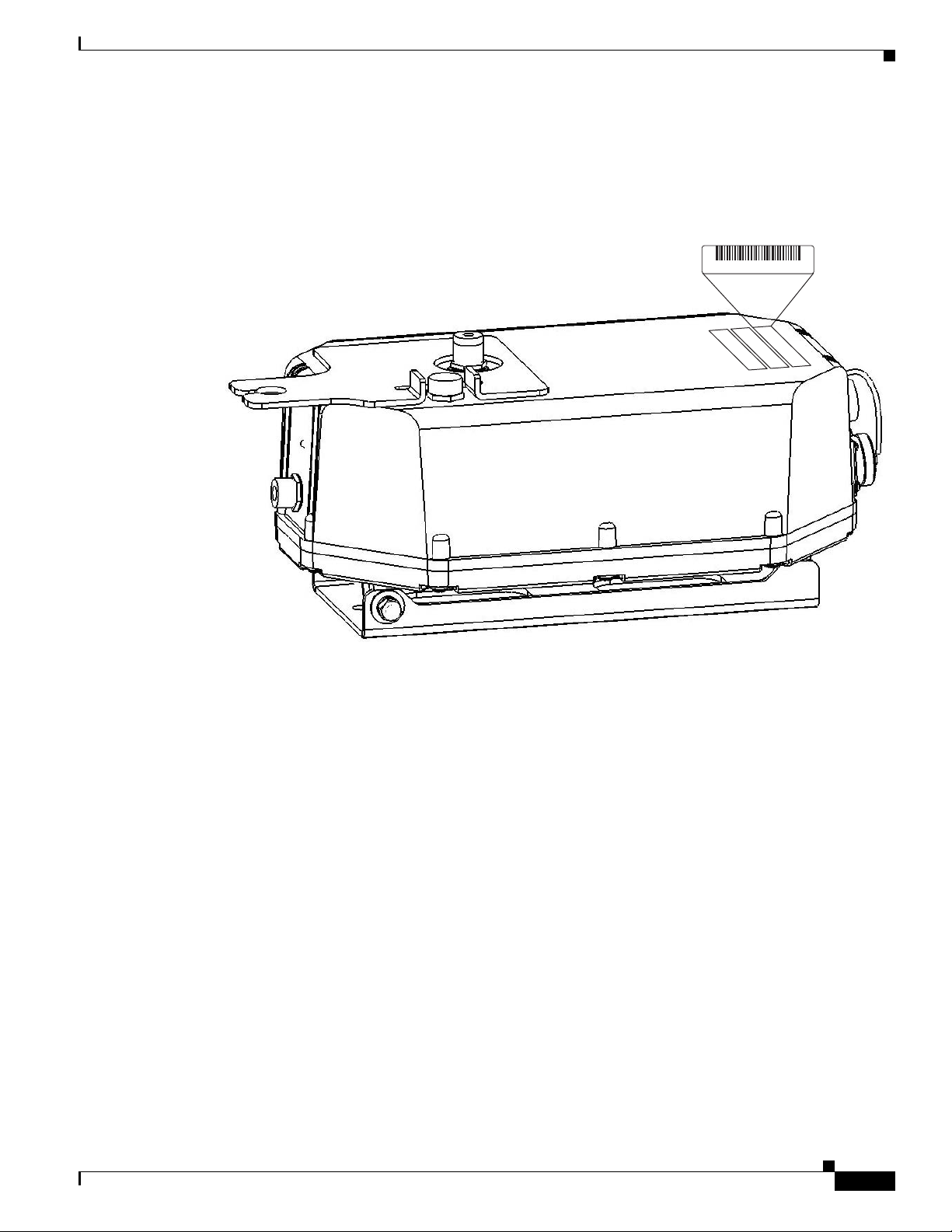
Finding the Product Serial Number
The access point seria l number is on th e right side of the housin g (refer to Figure 1).
Figure 1 Location of Serial Number Label
Obtaining Technical Assistance
SN: XXXNNNNXXXX
The access point serial number label contains the following information:
• Model number, such as AIR -LAP1 510AG-A-k9 or AI R-LAP 1505G -A-k9
• Serial number, such as WCN0636279B (11 alpha numer ic digits)
• MAC address, such as 00abc65094f3 (12 hexadecimal digits)
• Location of manufactu re, such as Made in Singapore
You need your product serial numb er when re questing sup port from the Cisco Technical Assistance
Center.
Submitting a Service Request
Using the online TA C Service Request Tool is the fastest way to open S3 and S4 service requests. (S3 and
S4 service requests are those in which your network is minim ally impai red or for whic h you require
product informat ion. ) Af ter yo u desc rib e your situ ati on, t h e TAC
recommended s oluti ons. I f your issu e is no t re so lved using t he r ecom me nd ed re so urce s, your se rv ice
request is assigned to a Cisco engineer. The TAC Service Request Tool is located at this URL:
http://www.cisco.com/techsupport/servicerequest
For S1 or S2 service r equests, o r if you do not ha v e Internet access, co ntact the C isco TAC b y telephone.
(S1 or S2 service requests are t hose in whic h your prod uction net work is down or severely degraded.)
Cisco engineers are assigned immediately to S1 and S2 service requests to help keep your business
operations running smoothly.
155960, 781-00455-01 A0
Service Re quest Tool provides
OL-9977-05
Cisco Aironet 1500 Series Outdoor Mesh Access Point Hardware Installation Guide
xiii
Page 18

Obtaining Additional Publications and Information
To open a servic e request by telephone, use one of the fo llowing number s:
Asia-Pacific: +61 2 8446 7411
Australia: 1 800 805 22 7
EMEA: +3 2 2 704 55 55
USA: 1 800 553 2 447
For a complete list of Cisco TAC contacts, go to this URL:
http://www.cisco.com/techsupport/contacts
Definitions of Service Request Severity
To ensure that all service requests are reported in a standard format, Cisco has established severity
definitions.
Severity 1 (S1)—An existing network is “down” or there is a critical impact to your business operations.
You and Cisco will commit all necessar y resource s aroun d the cloc k to resolve the situation.
Severity 2 (S2)—Operation of an existing network is severely degraded, or significant aspe cts of your
business operations are negatively affected by inadequate performance of Cisco products. You and Cisco
will commit full-time resources during normal business hours to resolve the situation.
Preface
Severity 3 (S3)—Operational perform ance of the ne twork is impa ired while most business oper ation s
remain functional. You and Cisco will commit resources during normal business hours to restore service
to satisfactory levels.
Severity 4 (S4)—You require information or assistance with Cisco product capabilities, installation, or
configuration. There is littl e or no effect on you r business operations.
Obtaining Additional Publications and Information
Information about Cisco products, technologies, and network solutions is available from various online
and printed sources.
• The Cisco O nline Subsc ription Center is the websit e where you ca n sign up for a variety of Cisco
e-mail newsletter s and o ther communic ations . Create a prof il e and th en selec t the sub scriptio ns that
you would like to receive. To visit the Cisco
http://www.cisco.com/offer/subscribe
• The Cisco Product Quick Reference Guide is a handy, compact reference tool that includes brief
product overviews, key features, sample part numbers, and abbreviated techni cal spe cifications for
many Cisco
the latest Cisco channel product offerings. To order and find out more about the Cisco
Reference Guide, go to this URL:
http://www.cisco.com/go/guide
• Cisco Marketplace provi des a variety of Cisco books, refe rence gui des, doc umenta tion, and l ogo
merchandise. Visit Cisco
products that are sold through channel partners. It is updated twice a year and includes
Marketplace, the company store, at this URL:
Online Subscription Center, go to this URL:
Product Quick
xiv
http://www.cisco.com/go/marketplace/
• Cisco Press publishes a wide range of general networking, training, and certification titles. Both new
and experienced users will bene fit from these pub lica tio ns. For curr ent Cisco
information, go to Cisc o
http://www.ciscopress.com
Cisco Aironet 1500 Series Outdoor Mesh Access Point Hardware Installation Guide
Press at this URL:
Press titles and other
OL-9977-05
Page 19

Preface
Obtaining Additional Publications and Information
• Internet Protocol Journal is a quarterly journal publ ished by Ci sco for eng in eerin g p rof ess iona ls
involved in designing, developing, and operating public and private internets and intranets. Y ou can
access the Internet Protocol Journal at this URL :
http://www.cisco.com/ipj
• Networking products offered by Ci sco, a s we ll as cust omer su ppo rt se rv ices , ca n be o bt ain ed a t
this
URL:
http://www.cisco.com/en/US/products/index.html
• Networking Professionals C onnec tion is an int era ctive website w here n etworking pr ofessi onal s
share questions, sug ges tions, and i nform at ion about ne twork ing p ro duct s and tec hn ologie s w ith
Cisco experts and other networking prof essiona ls. Join a discussi on at this URL:
http://www.cisco.com/discuss/networking
• “What’ s New in Cisco Documentation” is an online publication that provides information about the
latest documentation releases for Cisco products. Updated monthly, this online publication is
organized by product category to direct you qui ckly t o the docum entati on for your products . You
can view the latest r elea se of “W hat ’s New in Cisco
http://www.cisco.com/univercd/cc/td/doc/abtunicd/136957.htm
Documentation” at this URL:
• World-class net working training is available from Cisco. You can view current offerings at
this
URL:
http://www.cisco.com/en/US/learning/index.html
OL-9977-05
Cisco Aironet 1500 Series Outdoor Mesh Access Point Hardware Installation Guide
xv
Page 20

Obtaining Additional Publications and Information
Preface
xvi
Cisco Aironet 1500 Series Outdoor Mesh Access Point Hardware Installation Guide
OL-9977-05
Page 21

CHA PTER
1
Overview
The Cisco Aironet 1500 Ser ies Outdoo r Mesh Acc ess Point (h ereaft er cal led the acce ss po int) is a
wireless device designed for wireless client access, point-to-point bridging, point-to-multipoint
bridging, and point-to-multipoint mesh wireless connectivity. The access point is a standalone unit that
can be mounted on a str eet lig ht p ole or on a building wal l or overhang .ac cess p oint
The access po int i s available in two mode ls : L AP1510 (s uppo rts 2.4 -G Hz an d 5-G Hz ra dio s) a nd
LAP1505 (supports a 2.4-GHz radio).The access point provides client access and supports 6 to 54 Mbps
data rates without the ne ed for a lice nse. Th e LAP1510 mo del dedic ates the 5-G Hz radio for back haul
operations to reach a wired network and uses the 2.4-GHz radio for wireless clients. The LAP1505 model
uses the 2.4-GHz radio fo r both back haul and wi reless clie nts.
The access point can also operate as a relay node for other access points not directly connected to a wired
network. Intelligent wireless r outing is p rovid ed b y the paten t-pending Ad apti v e Wireless Path Protocol
(AWPP). This enables each access point to identify its neighbors and intelligently choose the optimal
path to the wired netw ork b y ca lcula ting the c ost of e ach pa th in ter ms of signal str ength and the n umber
of hops required to g et to a c ont roll er.
The access point is configured, monitored, and operated through a Cisco wireless LAN controller
(hereafter ca lled a controller) as described in the Cisco Wireless LAN Controller Configuration Guide.
The Deployment Guide: Ci sco Mesh Netw orki ng Solu tion describes how to plan and initially configure
the Cisco Mesh network, which suppor ts wireless poin t-to-p oint, point- to-mult ipoint, and me sh
deployments. The controllers use a browser-based management system, a command-line interface (CLI),
or the Cisco Wireless Control System (WCS) network management system to manage the controller and
the associated access points. The access point is compliant with Wi-Fi Protected Access (WPA2) and
employs hardware-base d Advanced E ncryp tion Sta nda rd ( AE S) en crypt ion b etw een w ire less nodes t o
provide end-to-end se cu rity.
This chapter provides information on the following topics:
• Hardware Features , pa ge 1-2
• Network Configuration Examp les, page 1-6
OL-9977-05
Cisco Aironet 1500 Series Outdoor Mesh Access Point Hardware Installation Guide
1-1
Page 22
Hardware Features
Hardware Features
Some of the access point hardware features are listed below:
• Dual simultaneous 2.4- a nd 5-GHz radio oper ation (see th e “Single or Dual Radio Operation”
section on page 1-3)
• External antennas (s ee t he “E xte rnal Ant enna s” se ctio n o n pag e 1-3)
• Multiple power so ur ce s ( see th e “Mu ltiple Power Sour ces” sec tion o n page 1-4)
• Ethernet port see the “Eth erne t Port” sec tion on page 1-5)
• Metal enclosure supports outdo or installa tions (see the “Metal Enclosure” section on page 1-6
–
Industrial temperature rating
• Optional pole mount kit (see the “Optional Hardware” section o n page 1-6)
• Optional streetlight power tap adapter (see the “Optional Hardware” section on page 1-6)
• Optional 150 ft (45.72 m) Ethernet outdoor cable (see the “Optional Hardware” section on page 1-6)
Figure 1-1 shows the access point connectors.
Chapter 1 Overview
Figure 1-1 Access Point Connectors
1 5.8-GHz an tenna br acket
4 Ethernet (PoE) connec tor (MS311 2P14-12 P)
(LAP1510 model only)
2 Vent (do not remove) 5 AC power connector (MS3112P14-5P)
3 2.4-GHz Type N antenna conne ct or 6 5.8-GHz Type N antenna connector
(LAP1510 model on ly )
1-2
Cisco Aironet 1500 Series Outdoor Mesh Access Point Hardware Installation Guide
OL-9977-05
Page 23

Chapter 1 Overview
Connectors
The access po int sup port s f our conn ec tors (s ee Figure 1-1):
• Ethernet (PoE) connect or—12 pi n circula r Mil spec (M S3112P14-12P)
• AC power connector—5 pin circular Mil spec (MS3112P14-5P)
• 2.4-GHz Type N antenna connect or
• 5-GHz Type N antenna connector ( LA P1510 m ode l o nly)
Single or Dual Radio Operation
The access po int i s available in two mode ls : L AP1510 (s uppo rts 2.4 -G Hz an d 5-G Hz ra dio s) a nd
LAP1505 (supports on ly a 2.4-GHz radio). The radios use external antenna s (see
The LAP1510 model supp orts si mul tane ous dual -rad io ope rat ion u si ng a 2. 4-GH z 802 .11 b/g rad io an d
a 5-GHz 802.11a radio.The 5-GHz radio incorporates an Unlicensed National Information Infrastructure
(UNII) radio transceiver operating in the UNII 5-GHz frequency ba nds. The 5-GHz radio on the access
point is used for backhaul operations to the controller. The 5-GHz radio can also operate in the 4.9-GHz
Public Safety band in the United States.
Hardware Features
“External Antennas”).
Note The 4.9-GHz band requi res a licen se and may b e used only by qualified Public Safety opera tors as
defined in section 90.20 of t he FC C r ules.
The LAP1505 model suppor ts both mesh bac khaul opera tion and wir eless clien ts using the 2.4 -GHz
radio.
External Antennas
The access point is equi pped with an N-ty pe radio freq uenc y (RF) co nne ctor on th e lar ge fl at side of the
unit for an external 2.4-GHz antenna. The LAP1510 model also has an N-type RF connector on the e nd
of the unit for an external 5-GHz antenna (see
omnidirectional antennas, the 2.4-GHz antenna connects directly to the access point, and the 5-GHz
antenna connects to the access point using the antenna’s included coax cable.
The Cisco omnidirectional external antennas use vertical polarization.
The access po int c an al so be e quipp ed wi th sp ec ific th ird- part y externa l a nte nna s (se e Table 1-1 and
Table 1-2 ), subject to local regulatory requirements. When you are installing third-party antennas, they
must be installed with all waterproofing steps recommended by the third-party manufacturer.
Note When you mount t he a ccess p oi nt in a n indoo r environmen t, you must al so mou nt the a nte nnas i n an
indoor environment.
Figure 1-1). When using the optional Cisco external
OL-9977-05
Warning
Only trained and qualified personnel should be allowed to install, replace, or service this equipment.
Statement 1030
Cisco Aironet 1500 Series Outdoor Mesh Access Point Hardware Installation Guide
1-3
Page 24
Hardware Features
Chapter 1 Overview
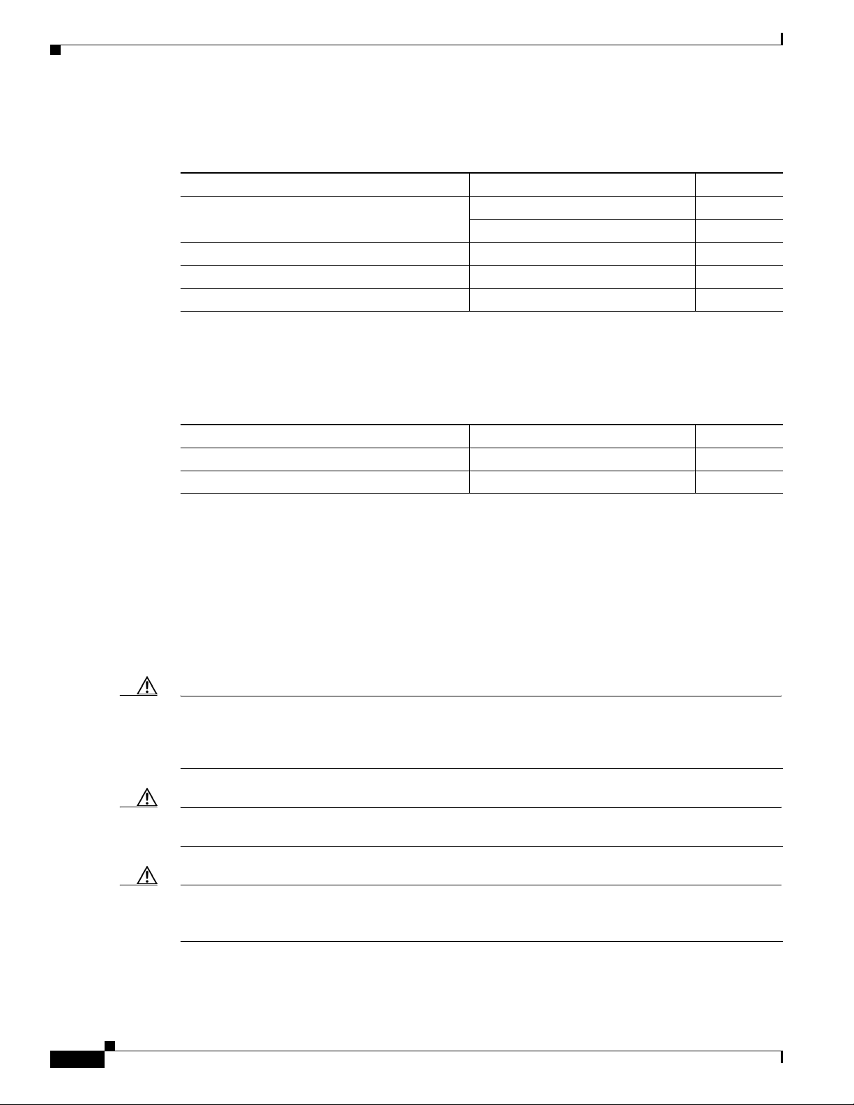
Table 1-1 and Table 1-2 lists the supported external antennas for the access point.
Ta b l e 1-1 External 5-GHz Antennas
Part Number Model Gain (dBi)
AIR-ANT5175V-N 4.9 GHz Compact omnidirec tional
AIR-ANT58G10SSA-N 5 GHz Sector 9.5
Cushcraft S49014WP (third pa rty) 5 GHz Patch 14
Cushcraft S54717P (third part y) 5 GHz Patch 17
1. Not supported on the LAP1505 model.
2. The use of the 4.9-GHz band requires a license and may be used onl y by qualif ied Public Safe ty operators as def ined in sect ion
90.20 of the FC C ru le s.
Ta b l e 1-2 External 2.4-GHz Antennas
Part Number Model Gain (dBi)
AIR-ANT-2455V-N 2.4 GHz Compact Omnidirecti onal 5.5
Cushcraft S2406BP (third party ) 2.4 GHz Omnidirec tiona l 8
Multiple Power Sources
1
2
6.5
5 GHz Compact omni dire ct ional 7.5
The access poin t c an be powered by o ne of the se p ower source s:
• 48 VDC inline p ower-over-Ethernet (P oE)
• AC p o we r
Inline PoE is provided by a shielded Ethernet cable using the Cisco Aironet Power Injector (AIRPWRINJ1500=), hereaf ter ca lled the po wer injector.
Caution To provide inline PoE, you must use the power injector (AIR- PWRINJ1500=) specified for the access
point. Other power injectors, PoE switches, and 802.3af power sources may not provide adequate power,
which may cause the access poi nt to malfu nction and ca use o v er -cur rent cond itions at th e po wer source .
You must ensure that the switch port connected to the access point has PoE turned off.
Caution The power injector (AIR- PWRINJ 1500=) has been evaluated for installation in an indoor environment
only.
Caution When the access point is installed outdoors or in a wet or damp location, the AC branch circuit that is
powering the access point should be provided with ground fault protection (GFCI), as required by Article
210 of the National Electrical Code (NEC).
1-4
Cisco Aironet 1500 Series Outdoor Mesh Access Point Hardware Installation Guide
OL-9977-05
Page 25

Chapter 1 Overview
Note The maximum Ethern et cabl e length i s 128 ft. (38 m) fro m the sw itch to the power injector an d 200 ft.
Hardware Features
(61 m) from the power injector to the access point.
AC power is provided from an AC power source (100 to 240 VAC at 50/60 Hz):
• AC power cord options:
–
15-ft (4.6-m) power cord (AIR -CORD15 00-15NA=) for u se in the US a nd Canada.
–
40-ft (12.2-m) power cord (AIR-CORD1500-40NA=) for light pole installations in the US and
Canada.
–
40-ft (12.2-m) power cord (A IR -CORD 1 500 -40UE =) f or u se outsi de t he U S a nd Can ada. One
end of the power cord is terminated with an access point AC power connector and the other end
is unterminated.
–
4-ft (1.2-m) streetlight power tap adapter (AIR-PWR-ST-LT-TAP=) for light pole installations
in the US and Canada.
Note For important safety instructions for AC power cords, refer to the AC P ower Cords for Cisco
Aironet 1500 Series Outdoor Mesh Access Points document that shipped with you r AC
power cords.
Ethernet Port
Tip The access point senses the Ethernet and power signals and automatically switches internal circuitry to
Caution To provide inline PoE, you must use the power injector (AIR- PWRINJ1500=) specified for the access
The access point’s Ethernet port uses a Mil-spec 12 pin connec tor, linking the access point t o your
10BASE-T or 100BASE-T Ethernet LAN throu gh the op tional power in jector. The shielded Ethe rnet
cables are used to send and rece ive Ethernet data an d to optio nally su pply inlin e 48-VDC power from
the power injector.
The Ethernet MAC address is printed on the label on the side of the acce ss point (ref er to the “ Findi ng
the Product Serial Number” section on page xiii).
match the cable connections.
point. Other power injectors, PoE switches, and 802.3af power sources may not provide adequate power,
which may cause the ac ce ss p o int to malfunction and cause over-current conditions at the power source.
OL-9977-05
Cisco Aironet 1500 Series Outdoor Mesh Access Point Hardware Installation Guide
1-5
Page 26

Network Configuration Examples
Metal Enclosure
The access po int uses a me tal en cl osure th at ca n acco mm oda te bo th in door or o utdoo r ope rat ing
environments and an industrial temperature operating range of –40°C (–40°F) to +55°C (+131°F). The
access point comp lies wit h NEMA Type 4X and IP66 re quir emen ts fr om I EC6052 9.
The access point is shipped with a mounting plate attached to the unit.
Note When the access point is mo unte d in doors, t he a ntenna s m ust also be m oun ted indo ors.
Optional Hardware
Some of the access point hardware options are listed below:
• Pole mount kit (AIR-A C CP MK 15 00 =) -—provides hardware for mounting the access point to the top
of a metal pole, such as a streetlight pole.
• Streetlight power tap adapter (AIR-PWR-ST-LT-TAP=)—connects to the light control connector on
a streetlight pole and provides AC power to the access point.
Chapter 1 Overview
• Outdoor rated Ethernet cable (AIR-ETH1500-150=)—used to sup ply Ethernet and optional D C power
to the access point.
• Power injector (AIR-PWRINJ1500=)—provides power-over-Ethernet (PoE) to the access point.
• AC power cord (for additional informat ion, refe r to the “Multiple Power Sources” section on
page 1-4).
Network Configuration Examples
The access poin t is a wir eless d evice desi gned fo r wir eless c lien t a cce ss and po int -to-p oint bri dgin g,
point-to-multipoint bridging, and point-t o-multi point mesh w ireless conne ctivity. The access point
provides 5-GHz back ha ul c apab ilit y to li nk wi th a not her ac cess point to r eac h a wir ed ne twork
connection or to provide repeat er operat ions for other access points.
The access point plays two primary radio roles: a root access point ( hereafter called a RAP) or a non-root
access point (hereafter called a MAP). When the access point has a wired Ethernet connection to the
controller (throu gh a sw itch) , the radi o role is ca ll ed a RAP. A RAP is a parent node to any bridging or
mesh network. A controller ca n suppor t one or more RAPs, each one pa renting t he same or different
wireless networks. There can be more t han o ne R AP for t he sam e mesh ne twork f or red unda ncy. RAPs
also support wireless clients on th e band not bei ng used for the backh aul inte rface.
When the access point does not have a wired Ethernet connection to the controller (through a switch),
the radio role is called a MA P. The MAPs have a wireless con necti on (throug h the back haul int erface)
to other MAPs and final ly to a RA P wit h an Eth erne t c onn ect ion thro ugh a swit ch t o the c ontro ller.
MAPs may also ha v e a wi red E thern et connec tion to a loc al LAN an d se rve a s a b ridge en dpoin t for that
LAN (using a poi nt-to- poin t or po i nt-to- mult ipoin t brid ge c onn ecti on) . MA Ps also sup port wi reless
clients on the band not used for the backhau l interfac e.
1-6
Cisco Aironet 1500 Series Outdoor Mesh Access Point Hardware Installation Guide
OL-9977-05
Page 27
Chapter 1 Overview
(2.4 Ghz)
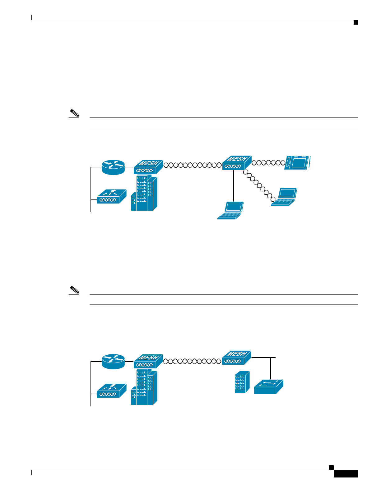
Wireless Backhaul
The access point supports wireless backhaul capability using the 5-GHz radio to bridge to another access
point to reach a wired net work conne ction to a contro ller (see
to the wired network is considered a RAP in this configuration. The remote access point is considered a
MAP and transfers wireless client traffic to the RAP for transfer to the wired network. Lightweight
access point protocol (LWAPP) control traffic is also transferred over this bridged link.
Note The LAP 1505 m odel us es t he 2 .4- GHz ra dio f or bac khaul and w ire les s c lient ope ra tions.
Figure 1-2 Access Point Backhaul Example
Network Configuration Examples
Figure 1-2). The access point connected
(5.8 Ghz)
Point-to-Point Bridging
The access points can be used to extend a remote network by usin g the 5-GHz backhaul radio to bridge
the two network segments as shown in
bridging on the controller for each acc ess point.
Note The LAP 1505 m odel us es t he 2 .4- GHz radio f or br idgi ng op er ati on s.
Wireless client access is sup por ted; however, if bridging between tall building s, the 2.4- Gh z w irele ss
coverage area may be limited and possib ly not suitabl e for direc t wireless cli ent access.
Figure 1-3 Access Point Point-to-Point Bridging Example
148438
Figure 1-3. To support E the rnet b ridging , you m ust e nabl e
OL-9977-05
148440
Cisco Aironet 1500 Series Outdoor Mesh Access Point Hardware Installation Guide
1-7
Page 28

Network Configuration Examples
148439
Point-to-Multipoint Bridging
The access points can be used as a RAP to connect multiple remote MAPs with their associated wired
networks (see
Ethernet bridging, you mu st enable br idging on the controller for each acc ess point.
Wireless client access can be provided over the bridging link; however, if bridging between tall
buildings, the 2.4-Ghz wireless coverage area may be limited and possibly not suitable for direct wireless
client access.
Figure 1-4 Access Point Point to Multipoint Bridging Example
Figure 1-4). By default this capability is turned-off for all access points. To support
Chapter 1 Overview
Mesh Network
Cisco Aironet 1500 Series Outdoor Mesh Access Point Hardware Installation Guide
1-8
The access points are typically deployed in a mesh network configuration. In a typical mesh deployment,
one or more RAPs have a wired network connection through a switch to a controller. Other remote MAPs
without wired network connections use the backhaul feature to optimally link to a RAP that is connected
to the wired network. In the mesh network, the links between the access points are referred to as the
backhaul links.
Intelligent wireless routing is pro vided b y the pat ent-pending Adapti v e Wireless Path protocol (AWPP).
This enables each MAP to i dent ify its neig hbor s an d i nte llig ently c hoose t he op timal pa th t o t he RA P
with the wired network connection by calculating the cost of each path in terms of signal strength and
the number of hops required to get to a cont roller.
OL-9977-05
Page 29

Chapter 1 Overview
Network Configuration Examples
Figure 1-5 illustrates a typical mesh configuration using MAPs and RAPs.
Figure 1-5 Typical Mesh Configuration Using Access Points
IP
155631
OL-9977-05
Cisco Aironet 1500 Series Outdoor Mesh Access Point Hardware Installation Guide
1-9
Page 30

Network Configuration Examples
158085
Layer 2 and Layer 3 Network Operation
The access poin ts su ppor t L ay er 2 or Lay er 3 ne twor k o pera tio n. In L ayer 2 configur ation s, t he a cce ss
point and the controller are on the same subnet and communicate with encapsulated Ethernet frames
using MAC addresses rather than IP addresses. Layer 2 configurations are typically not scalable into
larger networks. Additionally, Layer 2 operation is supporte d only by the Cisco 440 0 se ries cont ro ller s.
Access points and controller s in Layer 3 configurat ions use IP add resses and UDP packet s, which ca n
be routed through l arge netwo rks. L aye r 3 o pera tio n is sca lab le an d re comm end ed by Cisc o.
Figure 1-6 illustrates a typical Layer-3 wireless network configuration containing access points and a
controller.
Figure 1-6 Typical Layer 3 Access Point Network Configuration Example
Chapter 1 Overview
LWAPP
LWAPP
1-10
Cisco Aironet 1500 Series Outdoor Mesh Access Point Hardware Installation Guide
OL-9977-05
Page 31

Chapter 1 Overview
158084
Network Configuration Examples
Figure 1-7 illustrates a typical Layer 2 network conf ig ura tio n. I n a La ye r 2 c onfiguration, the controller
and the access points are on the same subnet.
Figure 1-7 Typical Layer 2 Access Point Network Configuration Example
LWAPP
LWAPP
OL-9977-05
Cisco Aironet 1500 Series Outdoor Mesh Access Point Hardware Installation Guide
1-11
Page 32

Network Configuration Examples
Chapter 1 Overview
1-12
Cisco Aironet 1500 Series Outdoor Mesh Access Point Hardware Installation Guide
OL-9977-05
Page 33

Cisco Confidential - Draft 1
CHAP T ER
2
Mounting Instructions
This chapter describes warnings, safety information, and mounting information needed during the
installation of your access point. The chapter contains these sections:
• Unpacking the Access Point, page 2-2
• Tools and Materials, page 2-2
• Warnings, page 2-3
• Safety Information, page 2-3
• Installation Guidelines, page 2-6
• Mounting the Access Point, page 2-11
OL-9977-05
Cisco Aironet 1500 Series Outdoor Mesh Access Point Hardware Installation Guide
2-1
Page 34

Unpacking the Access Point
Cisco Confidential - Draft 1
Unpacking the Access Point
Note When you are unpacking the access point, do not remove the foam blocks attached to the antenna
connectors. The foam protects the antenna connectors during installation.
Follow these steps to unpack the access point:
Step 1 Open the shipping container and carefully remove the contents.
Step 2 Return all packing materials to the shipping container and save it.
Step 3 Ensure that all items listed in Package Contents are included in the shipment. If any item is damaged or
missing, notify your authorized Cisco sales representative.
Package Contents
Chapter 2 Mounting Instructions
Each access point package contains the following items:
• Access point with mounting plate attached
• Cisco product documentation, translated safety warnings, registration and feedback cards
• Grounding lug with screw and lock washer
Tools and Materials
To install the access point you will need the following:
• Open and box-end wrenches or socket set and ratchet
• Customer-supplied 10-AWG copper ground wire
• Ground lug (Panduit PN-10-6R-2K) and screw with lock washer (supplied)
• Customer supplied crimping tool for the ground lug (Panduit PN-10-6R-2K)
• Optional power injector (AIR-PWRINJ1500=)
• Optional Ethernet cable
–
150-ft (45.72-m) Ethernet cable (AIR-ETH1500-150=)
–
Other lengths (user supplied)
• Optional AC power cord
–
15-ft (4.6-m) power cord (AIR-CORD1500-15NA=) for use in the US and Canada.
–
40-ft (12.2-m) power cord (AIR-CORD1500-40NA=) for light pole installations in the US and
Canada.
2-2
–
40-ft (12.2-m) power cord (AIR-CORD1500-40UE=) for use outside the US and Canada. One
end of the power cord is terminated with an access point AC power connector and the other end
is unterminated.
Cisco Aironet 1500 Series Outdoor Mesh Access Point Hardware Installation Guide
OL-9977-05
Page 35

Chapter 2 Mounting Instructions
• Optional pole mount kit (AIR-ACCPMK1500=)
• External antennas, 2.4 and 5 GHz (refer to the “External Antennas” section on page 1-3)
• Optional primary protector (user supplied), as required by local regulations
• Optional ladder, power lift, rope, or other tools as required
Warnings
Translated versions of all safety warnings are available in the safety warning document that shipped with
your access point or on Cisco.com. To browse to the document on Cisco.com, refer to
“Translated Safety Warnings” for instructions.
Warnings
Cisco Confidential - Draft 1
–
4-ft (1.2-m) streetlight power tap adapter (AIR-PWR-ST-LT-TAP=) for light pole installations
in the US and Canada.
Appendix 1,
Warning
Warning
Warning
Warning
Warning
IMPORTANT SAFETY INSTRUCTIONS
This warning symbol means danger. You are in a situation that could cause bodily injury. Before you
work on any equipment, be aware of the hazards involved with electrical circuitry and be familiar
with standard practices for preventing accidents. Use the statement number provided at the end of
each warning to locate its translation in the translated safety warnings that accompanied this device.
Statement 1071
SAVE THESE INSTRUCTIONS
Do not operate the unit near unshielded blasting caps or in an explosive environment unless the
device has been modified to be especially qualified for such use.
This equipment must be externally grounded using a customer-supplied ground wire before power is
applied. Contact the appropriate electrical inspection authority or an electrician if you are uncertain
that suitable grounding is available.
Read the installation instructions before connecting the system to the power source.
Ultimate disposal of this product should be handled according to all national laws and regulations.
Statement 1040
Statement 364
Statement 366
Statement 1004
Safety Information
Follow the guidelines in this section to ensure proper operation and safe use of the access point.
OL-9977-05
Cisco Aironet 1500 Series Outdoor Mesh Access Point Hardware Installation Guide
2-3
Page 36

Safety Information
Cisco Confidential - Draft 1
FCC Safety Compliance Statement
The FCC, with its action in ET Docket 96-8, has adopted a safety standard for human exposure to RF
electromagnetic energy emitted by FCC-certified equipment. When used with approved Cisco Aironet
antennas, Cisco Aironet products meet the uncontrolled environmental limits found in OET-65 and ANSI
C95.1, 1991. Proper operation of this radio device according to the instructions in this publication results
in user exposure substantially below the FCC recommended limits.
Safety Precautions
Chapter 2 Mounting Instructions
Warning
Warning
Warning
Warning
Warning
Warning
In order to comply with radio frequency (RF) exposure limits, the antennas for this product should be
positioned no less than 6.56 ft (2 m) from your body or nearby persons.
The AC power supply has double pole/neutral fusing.
Do not work on the system or connect or disconnect cables during periods of lightning activity.
Statement 1001
This equipment has been designed for connection to TN and IT power systems.
Only trained and qualified personnel should be allowed to install, replace, or service this equipment.
Statement 1030
Do not locate the antenna near overhead power lines or other electric light or power circuits, or
where it can come into contact with such circuits. When installing the antenna, take extreme care
not to come into contact with such circuits, because they may cause serious injury or death. For
proper installation and grounding of the antenna, please refer to national and local codes (for
example, U.S.:NFPA 70, National Electrical Code, Article 810, Canada: Canadian Electrical Code,
Section 54).
Statement 1052
Statement 188
Statement 339
Statement 1007
2-4
Caution No serviceable parts inside. Do not open.
Caution Double pole/neutral fusing. The power supply has two fuses and might have live circuits even when one fuse
has blown.
Note For additional important safety instructions for AC power cords, refer to the AC Power Cords for Cisco
Aironet 1500 Series Outdoor Mesh Access Points document that shipped with your AC power cords.
Cisco Aironet 1500 Series Outdoor Mesh Access Point Hardware Installation Guide
OL-9977-05
Page 37

Chapter 2 Mounting Instructions
Each year hundreds of people are killed or injured when attempting to install an antenna. In many of
these cases, the victim was aware of the danger of electrocution, but did not take adequate steps to avoid
the hazard.
For safety, and to help you achieve a good installation, please read and follow these safety precautions.
They may save your installer’s life!
1. Select your installation site with safety, as well as performance in mind. Remember: electric power
lines and phone lines look alike. For safety, assume that any overhead line can kill.
2. Call your electric power company. Tell them your plans and ask them to come look at your proposed
installation. This is a small inconvenience considering your installer’s life is at stake.
3. Plan your installation carefully and completely before you begin. Successful raising of a mast or
tower is largely a matter of coordination. Each person should be assigned to a specific task, and
should know what to do and when to do it. One person should be in charge of the operation to issue
instructions and watch for signs of trouble.
4. When installing the access point and antennas, remember:
Avoiding Damage to Radios in a Testing Environment
Cisco Confidential - Draft 1
a. Do not use a metal ladder.
b. Do not work on a wet or windy day.
c. Do dress properly—shoes with rubber soles and heels, rubber gloves, long sleeved shirt or
jacket.
5. Use a rope to lift the access point. If the assembly starts to drop, get away from it and let it fall.
6. If any part of the antenna system should come in contact with a power line, don’t touch it or try to
remove it yourself. Call your local power company. They will remove it safely.
If an accident should occur call for qualified emergency help immediately.
Avoiding Damage to Radios in a Testing Environment
The radios on outdoor units (bridges) have higher transmit power levels than radios on indoor units
(access points). When you test high power radios in a link, you must avoid exceeding the receiver’s
maximum receive input level. At levels above normal the operating range, packet error rate (PER)
performance is degraded. At even higher levels, the receiver can be permanently damaged. To avoid
receiver damage and PER degradation, you can use one of the following techniques:
• Separate the omnidirectional antennas by at least 2 ft (0.6 m) to avoid receiver damage or by at least
25 ft (7.6 m) to avoid PER degradation.
Note These distances assume free space path loss and are conservative estimates. Required
separation distances for damage and performance degradation levels in actual deployments will be less
due to non line-of-sight propagation conditions.
OL-9977-05
• Reduce the configured transmit power to the minimum level.
• Use directional antennas and keep them away from each other.
• Cable the radios together using a combination of attenuators, combiners, or splitters to achieve a total
attenuation of at least 60 dB.
Cisco Aironet 1500 Series Outdoor Mesh Access Point Hardware Installation Guide
2-5
Page 38

Installation Guidelines
Caution Under no circumstances should you connect the antenna port from one access point to the antenna port
Chapter 2 Mounting Instructions
Cisco Confidential - Draft 1
For a radiated test bed, the following equation describes the relationships among transmit power, antenna
gain, attenuation, and receiver sensitivity:
txpwr + tx gain + rx gain - [attenuation due to antenna spacing] < max rx input level
Where:
txpwr = Radio transmit power level
tx gain = transmitter antenna gain
rx gain = receiver antenna gain
For a conducted test bed, the following equation describes the relationships among transmit power,
antenna gain, and receiver sensitivity:
txpwr - [attenuation due to coaxial components] < max rx input level
of another access point without using an RF attenuator. If you connect antenna ports you must not exceed
the maximum survivable receive level of 0 dBm. Never exceed 0 dBm or damage to the access point can
occur. Using attenuators, combiners, and splitters having a total of at least 60 dB of attenuation ensures
that the receiver is not damaged and PER performance is not degraded.
Installation Guidelines
Because the access point is a radio device, it is susceptible to common causes of interference that can
reduce throughput and range. Follow these basic guidelines to ensure the best possible performance:
• For information on planning and initially configuring your Cisco Mesh network, refer to the
Deployment Guide: Cisco Mesh Networking Solution.
• Perform a site survey before beginning the installation.
• Install the access point in an area where structures, trees, or hills do not obstruct radio signals to and
from the access point.
• The access points can be installed at any height, but best throughput is achieved when all the access
points are mounted at the same height.
Note Cisco recommends installing the access points no higher than 40 feet to allow support for wireless clients
on the ground.
Note To calculate path loss and to determine how far apart to install access points, consult an RF planning
expert.
Site Surveys
2-6
Every network application is a unique installation. Before installing multiple access points, you should
perform a site survey to determine the optimum use of networking components and to maximize range,
coverage, and network performance.
Consider the following operating and environmental conditions when performing a site survey:
• Data rates—Sensitivity and range are inversely proportional to data bit rates. The maximum radio
range is achieved at the lowest workable data rate. A decrease in receiver sensitivity occurs as the
radio data increases.
Cisco Aironet 1500 Series Outdoor Mesh Access Point Hardware Installation Guide
OL-9977-05
Page 39

Chapter 2 Mounting Instructions
Cisco Confidential - Draft 1
• Antenna type and placement—Proper antenna configuration is a critical factor in maximizing radio
range. As a general rule, range increases in proportion to antenna height. However, do not place the
antenna higher than necessary, because the extra height also increases potential interference from
other unlicensed radio systems and decreases the wireless coverage from the ground.
• Physical environment—Clear or open areas provide better radio range than closed or filled areas.
• Obstructions—Physical obstructions such as buildings, trees, or hills can hinder performance of
wireless devices. Avoid locating the devices in a location where there is an obstruction between the
sending and receiving antennas.
Before Beginning the Installation
Before you begin the installation process:
• Ensure that a site survey has been performed.
• Ensure that your network infrastructure devices are operational and properly configured.
• Ensure that your controllers are connected to switch trunk ports.
• Ensure that your switch is configured with untagged access ports for connecting your access points.
• Ensure that a DHCP server with Option 43 configured is reachable by your access points or
manually configure the controller information in the access point (for additional information, refer
to the
“Configuring DHCP Option 43” section on page G-1).
Installation Guidelines
• Become familiar with the access point installation components (see the “Becoming Familiar with
Access Point Installation Components” section on page 2-7).
• Add the MAC addresses of the access points to the controller’s filter list (see the “Adding the Access
Point MAC Addresses to the Controller Filter List” section on page 2-10).
• Enable automatic configuration of access points on the controller (see the “Enabling Zero Touch
Configuration on the Controller” section on page 2-10).
Becoming Familiar with Access Point Installation Components
The access point is designed to be installed in an indoor or outdoor environment, such as an interior wall
or ceiling or the exterior roof overhang of a tall building or a streetlight pole.
Note When you mount access point in an indoor environment, you must also mount the attached antennas in
an indoor environment.
Carefully review the following figures to become familiar with the system components, connectors,
indicators, cables, system interconnection, and grounding:
• Components in a Typical Access Point Installation (Figure 2-1)
• Access point connectors (Figure 2-2)
• Streetlight power tap installation (Figure 2-3)
OL-9977-05
Cisco Aironet 1500 Series Outdoor Mesh Access Point Hardware Installation Guide
2-7
Page 40

Installation Guidelines
Chapter 2 Mounting Instructions
Cisco Confidential - Draft 1
Figure 2-1 Components in a Typical Access Point Installation
1
2
9
10 8
3
7
4
5
142678
6
1 Building roof-overhang 6 Ground
2 Outdoor rated shielded Ethernet cable
1
7 AC power cord
3 Water drip loop 8 Power injector
4 10-AWG copper grounding wire1 9 Ethernet (CAT 5) cable
2
3
1
5 Ground rod1 10 Controller (through a switch)
1. User supplied.
2. The safety ground wire in the AC power cord must have a ground path to a grounding rod.
3. The shielded Ethernet cable has a ground path through the power injector and the safety ground wire in the AC power cord.
Warning
Installation of the equipment must comply with local and national electrical codes.
Statement 1074
Note There is no requirement for external lightening arrestors on the 1510. The power supplies on the 1510
and the PoE in ports have transient voltage surge suppression. In addition, the PoE in port should be used
with shielded cables that are grounded at the access point and power injector.
2-8
Cisco Aironet 1500 Series Outdoor Mesh Access Point Hardware Installation Guide
OL-9977-05
Page 41

Chapter 2 Mounting Instructions
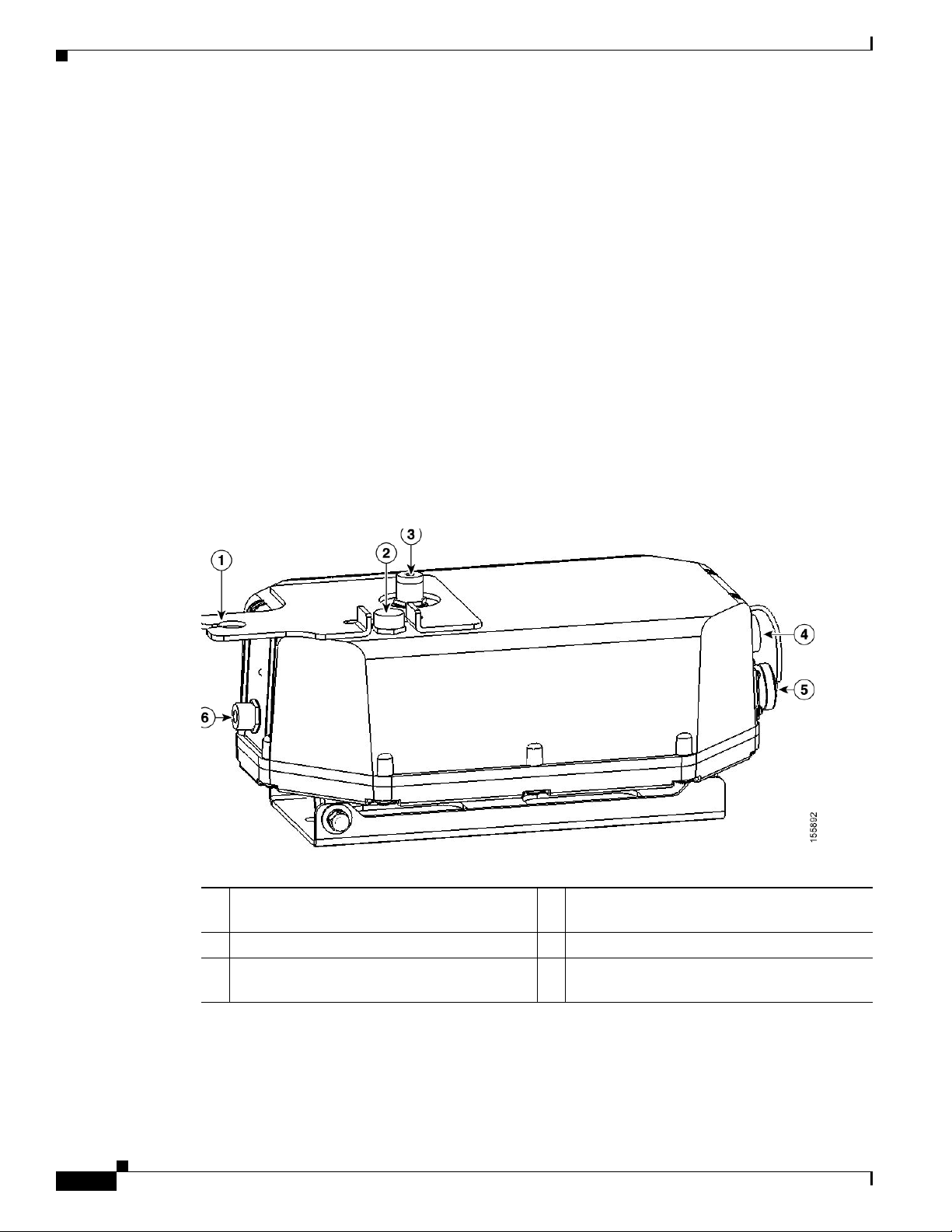
Figure 2-2 Access Point Connectors
Installation Guidelines
Cisco Confidential - Draft 1
1 5.8-GHz antenna bracket (LAP1510 model) 4 Ethernet (PoE) connector (MS3112P14-12P)
2 Vent (do not remove) 5 AC power connector (MS3112P14-5P)
3 2.4-GHz antenna connector (Type-N) 6 5.8-GHz Type N antenna connector
(LAP1510 model)
Figure 2-3 Streetlight Power Tap Adapter Installation
1
2
3
142680
OL-9977-05
1 Outdoor light control 3 10-AWG copper grounding wire
2 Streetlight power tap adapter
Cisco Aironet 1500 Series Outdoor Mesh Access Point Hardware Installation Guide
2-9
Page 42

Chapter 2 Mounting Instructions
Installation Guidelines
Cisco Confidential - Draft 1
Adding the Access Point MAC Addresses to the Controller Filter List
Prior to installing your access points, configure your controller by adding the MAC addresses of the
access points to the filter list and enable Zero Touch Configuration. This enables the controller to
respond to the listed access points and transfer the Bridge Shared Secret Key to each access point. The
secret key is required for the access points to communicate with other access points in the same bridge
group upon installation. Follow these steps to add a MAC filter entry on the controller:
Step 1 Log into your controller using a web browser.
Step 2 Choose SECURITY > MAC Filtering > New.
Step 3 Enter the MAC address of the access point to the MAC Filter list; for example, 00:0B:91:21:3A:C7.
Step 4 Select a WLAN ID or Any WLAN from the WLAN ID pop-up menu.
Step 5 Enter a description (32 characters maximum) of the access point in the Description field; for example,
Fisher_Street_00.0B.91.21.3A.C7 shows the location and MAC address of the access point.
Step 6 Choose an interface from the Interface Name pop-up menu and click Apply.
Step 7 Repeat Steps 2 to 6 to add other access points to the list.
Step 8 Log out of your controller and close your web browser.
Enabling Zero Touch Configuration on the Controller
Follow these steps to enable automatic configuration of access points on the controller:
Step 1 Log into your controller using a web browser.
Step 2 Choose WIRELESS > MESH.
Step 3 Check Enable Zero Touch Configuration.
Note If you do not specify a new bridging shared secret key and key format, the default or the existing
configured value is used.
Step 4 [Optional] Choose a key format by clicking the down arrow in the Key Format field.
Step 5 [Optional] Enter a new secret key and confirm the entry.
Step 6 Click Apply.
Note You can also use the controller CLI command config network zero-config to enable automatic
configuration.
2-10
Step 7 Log out from your controller and close your web browser.
Cisco Aironet 1500 Series Outdoor Mesh Access Point Hardware Installation Guide
OL-9977-05
Page 43

Chapter 2 Mounting Instructions
Configuring a RAP
The access point defaults to the MAP radio role. One or more of your access points must be reconfigured
as a RAP. The RAPs connect to a wired Ethernet link through a switch to the controller. The MAPs use
their wireless backhaul interface to connect to a RAP to reach the controller.
Follow these steps to configure a RAP on the controller:
Step 1 Log into your controller using a web browser.
Step 2 Click Wireless. When your access point associates to the controller, your access point’s name is visible
in the AP Name list.
Step 3 Find your access point’s name and click Detail.
Step 4 Find Bridging Instructions and choose Root AP by clicking the drop down arrow in the AP Role field.
Step 5 Click Apply.
Step 6 Repeat Steps 2 through 5 for each RAP.
Step 7 Log out from your controller and close your web browser.
Mounting the Access Point
Cisco Confidential - Draft 1
Mounting the Access Point
This section provides instructions for installing your access points. Personnel installing the access point
must understand wireless access points and bridging techniques and grounding methods.
Installation Options
There are two common installation methods: a roof-overhang or wall installation using the access point
mounting plate (supplied) or a pole installation using the optional pole mount kit.
Warning
Warning
Caution When the product is installed outside of the building, and the DC power/Ethernet connection is used, this
Only trained and qualified personnel should be allowed to install, replace, or service this equipment.
Statement 1030
Installation of the equipment must comply with local and national electrical codes.
cabling should be installed in accordance with the requirements of a Class 2 circuit, as detailed in Article
725 of the National Electric Code (NEC). Such requirements include, but are not limited to, routing the
Class 2 cabling away from AC power lines and AC building wiring, and limiting the exposed cable runs
external to the building to less than 140 ft (42m) – or is directly buried or in underground conduit, where
a continuous metallic cable shield or a continuous metallic conduit containing the cable is bonded to
each building grounding electrode system. If such installation methods are not followed, the cabling
must be installed according to the requirements for telecommunication circuits (TNV) as detailed in
Statement 1074
OL-9977-05
Cisco Aironet 1500 Series Outdoor Mesh Access Point Hardware Installation Guide
2-11
Page 44

Mounting the Access Point
Article 800, which includes requirements for a Listed primary protector upon entering the building, and
limits the installation to only Listed networking equipment designed to accommodate telecommunication
interfaces.
Caution To provide inline PoE, you must use the power injector (AIR- PWRINJ1500=) specified for the access
point. Other power injectors, PoE switches, and 802.3af power sources may not provide adequate power,
which may cause the access point to malfunction and cause over-current conditions at the power source.
You must ensure that the switch port connected to the access point has PoE turned off.
Refer to these sections for installation details.
• Access Point Mounting Orientations, page 2-12
• Mounting the Access Point on a Vertical or Horizontal Surface, page 2-15
• Roof-Overhang Installation, page 2-16
• Mounting the Access Point on a Pole, page 2-17
• Streetlight Pole Installations, page 2-21
Chapter 2 Mounting Instructions
Cisco Confidential - Draft 1
Access Point Mounting Orientations
When installing an access point on a horizontal or vertical surface, you must ensure that the access point
is correctly oriented.
Caution When mounting the access point in a horizontal position, you must position the side with the 2.4-GHz
antenna connector facing down (see
position, you must position the access point with the 5-GHz antenna connector facing up (see
Figure 2-5). This positioning is required to prevent water intrusion into the unit from the vent. You must
ensure that the vent is not obstructed by anything.
Figure 2-4). When you are mounting the access point in a vertical
2-12
Cisco Aironet 1500 Series Outdoor Mesh Access Point Hardware Installation Guide
OL-9977-05
Page 45

Chapter 2 Mounting Instructions
Figure 2-4 Preferred Horizontal Orientation
Mounting the Access Point
Cisco Confidential - Draft 1
1
2
3
142681
1 5-GHz antenna connector (LAP1510 model) 3 2.4-GHz antenna connector (this side down)
2 5-GHz antenna cable (LAP1510 model)
OL-9977-05
Cisco Aironet 1500 Series Outdoor Mesh Access Point Hardware Installation Guide
2-13
Page 46

Mounting the Access Point
Figure 2-5 illustrates the access point vertical orientation.
Figure 2-5 Optional Vertical Orientation
Chapter 2 Mounting Instructions
Cisco Confidential - Draft 1
1
2
142682
3
1 5-GHz external antenna connector
3 This end must be down
(LAP 1510 model)
2 2.4-GHz external antenna connector
Note Omnidirectional antennas must be mounted vertically.
2-14
Cisco Aironet 1500 Series Outdoor Mesh Access Point Hardware Installation Guide
OL-9977-05
Page 47

Chapter 2 Mounting Instructions
Cisco Confidential - Draft 1
Mounting the Access Point on a Vertical or Horizontal Surface
To mount the access point on a vertical or horizontal surface such as a wall or a roof-overhang, use the
supplied mounting plate. For the correct access point mounting orientations, refer to the
Mounting Orientations” section on page 2-12.
Step 1 The mounting plate is attached to the access point by two carriage bolts. Refer to Figure 2-6 for the
location of the carriage bolts securing the mounting plate.
Figure 2-6 Access Point Mounting Plate and Carriage Bolts
2
1
Mounting the Access Point
“Access Point
2
3
170061
1 Mounting plate 3 Grounding screw hole
2 Carriage bolts
Step 2 Remove the nuts and washers from the carriage bolts and remove the carriage bolts.
Step 3 Remove the mounting plate from the access point.
OL-9977-05
Cisco Aironet 1500 Series Outdoor Mesh Access Point Hardware Installation Guide
2-15
Page 48

Mounting the Access Point
Step 4 Use the mounting plate as a template to mark four screw hole locations on your mounting surface. See
Figure 2-7 for the mounting plate screw hole locations.
Caution The mounting surface, attaching screws, and optional wall anchors must be able to support a 50 lbs
(22.7 kg) static weight.
Figure 2-7 Mounting Plate Screw Hole Locations
Chapter 2 Mounting Instructions
Cisco Confidential - Draft 1
1
1 Four locations
Step 5 Use four customer-supplied screws and optional screw anchors to attach the mounting plate to the
mounting surface.
Note If necessary, use suitable screw anchors and an exterior-grade plywood backboard to mount the
access point to stucco, cement, or drywall.
Step 6 Use the carriage bolts and the associated nuts and washers to reattach the access point to the mounting
plate. Tighten the nuts to 61 to 71 in. lbs (6.89 to 8.02 Nm).
Step 7 Continue with the “Roof-Overhang Installation” section.
Roof-Overhang Installation
When your access point is mounted on a roof overhang, follow these steps to complete the installation:
Step 1 Review Figure 2-1 to identify the components needed for the installation.
Step 2 Connect a Category 5 Ethernet cable from your wired LAN network to the optional power injector.
142684
2-16
Cisco Aironet 1500 Series Outdoor Mesh Access Point Hardware Installation Guide
OL-9977-05
Page 49

Chapter 2 Mounting Instructions
Caution When the product is installed outside of the building, and the DC power/Ethernet connection
Use only the specified power injector (AIR-PWRINJ1500=) for the access point. This power injector is
designed to meet the power requirements of the access point and is a listed Class
(LPS).
Mounting the Access Point
Cisco Confidential - Draft 1
is used, this cabling should be installed in accordance with the requirements of a Class 2
circuit, as detailed in Article 725 of the National Electric Code (NEC). Such requirements
include, but are not limited to, routing the Class 2 cabling away from AC power lines and AC
building wiring, and limiting the exposed cable runs external to the building to less than 140
ft (42 m) – or is directly buried or in underground conduit, where a continuous metallic cable
shield or a continuous metallic conduit containing the cable is bonded to each building
grounding electrode system. If such installation methods are not used, the cabling must be
installed according to the requirements for telecommunication circuits (TNV) as detailed in
Article 800, which includes requirements for a Listed primary protector upon entering the
building, and limits the installation to only Listed networking equipment designed to
accommodate telecommunication interfaces.
2 Limited Power Source
Tip To forward bridge traffic, add a switch between the power injector and controller. Refer to the
Deployment Guide: Cisco Mesh Networking Solution for more information.
Step 3 Ensure the antennas are connected to the access point before you apply power to the access point.
Step 4 Connect a shielded outdoor-rated Ethernet cable (such as AIR-ETH1500-150=) between the power
injector and the access point’s Ethernet connector (see
Note You should hand-tighten the access point Ethernet cable connector until the connector locks.
Warning
Step 5 When using the optional Cisco external omnidirectional antennas, connect them to the access point as
Use the captive connector cap on the unused mil spec connector to prevent water intrusion and
possible safety hazards.
shown in
Figure 2-1. When using other Cisco external antennas, mount them as directed by the
Statement 362
Figure 2-2).
installation documentation that shipped with the antennas.
Step 6 When using optional third-party external antennas, mount and connect them as described in the
installation documents that shipped with the antennas.
Step 7 Continue with the “Grounding the Access Point” section on page 2-21.
Mounting the Access Point on a Pole
When installing an access point on a pole or mast, you should use the optional Cisco pole mount kit. To
mount the access point on a pole, perform these steps:
Cisco Aironet 1500 Series Outdoor Mesh Access Point Hardware Installation Guide
OL-9977-05
2-17
Page 50

Mounting the Access Point
Step 1 From the pole mount kit, use four of the supplied short bolts, lock washers, and flat washers to attach
the pole mount kit adjustment plate to the access point mounting plate as shown in
the bolts to 15 to 20 ft. lbs. (20 to 27 Nm).
Figure 2-8 Adjustment Plate Attached to the Mounting Plate
Chapter 2 Mounting Instructions
Cisco Confidential - Draft 1
Figure 2-8. Tighten
142686
Step 2 Select a mounting location. You can attach the access point to any pole from 1.66 to 3.35 in. (4.22 to
9.02 cm) in diameter.
Note If you will be using a streetlight power tap adapter, position the access point within 3 ft (1 m) of
the outdoor light control.
Step 3 Loosely assemble the pole clamp components around the pole and thread the four long bolts into the
clamp adjustment plate.
Figure 2-9 shows the pole clamp attached to a pole with the clamp adjustment
plate positioned on the bolts.
2-18
Cisco Aironet 1500 Series Outdoor Mesh Access Point Hardware Installation Guide
OL-9977-05
Page 51

Chapter 2 Mounting Instructions
Figure 2-9 Pole Clamp and Clamp Adjustment Plate Mounted on a Pole
Step 4 Adjust the top edge of the pole clamp until it is horizontal and tighten the bolts to 15 to 20 ft. lbs. (20
to 27 Nm)
Mounting the Access Point
Cisco Confidential - Draft 1
142687
Note If you need longer bolts, purchase 3/8–16 bolts of the correct length for your installation. Also,
the bolts can protrude up to 2 in (5 cm) and still allow the pole mount assembly to swivel and
rotate.
OL-9977-05
Cisco Aironet 1500 Series Outdoor Mesh Access Point Hardware Installation Guide
2-19
Page 52

Mounting the Access Point
Step 5 From the pole mount kit, use the two short bolts, lock washers, and flat washers to loosely attach the two
adjustment plates as shown in
Note Do not over-tighten the bolts. You will need to adjust the access point orientation.
Figure 2-10 Access Point Attached to the Pole Clamp
Chapter 2 Mounting Instructions
Cisco Confidential - Draft 1
Figure 2-10.
142688
Step 6 If necessary, rotate the access point until the top edge of the housing is horizontal, and tighten the two
short bolts on the adjustment plates. Torque the bolts to 15 to 20 ft. lbs. (20 to 27 Nm).
Step 7 Continue with the “Grounding the Access Point” section on page 2-21.
2-20
Cisco Aironet 1500 Series Outdoor Mesh Access Point Hardware Installation Guide
OL-9977-05
Page 53

Chapter 2 Mounting Instructions
Cisco Confidential - Draft 1
Grounding the Access Point
Mounting the Access Point
Warning
Warning
This equipment must be externally grounded using a customer-supplied ground wire before power is
applied. Contact the appropriate electrical inspection authority or an electrician if you are uncertain
that suitable grounding is available.
Installation of the equipment must comply with local and national electrical codes.
Statement 366
Statement 1074
In all outdoor installations and when powering the access point with AC power, you must follow these
instructions to properly ground the case:
Step 1 If using insulated 10-AWG copper ground wire, strip the insulation as required for the grounding lug.
Step 2 Use the appropriate crimping tool to crimp the bare 10-AWG copper ground wire to the grounding lug
(Panduit PN-10-6R-2K lug supplied).
Step 3 Connect the grounding lug to the access point grounding screw hole using the supplied Phillips head
screw (6-32x1/4 stainless steel) with lock washer (McMaster-Carr 95345A458 or equivalent). The
grounding screw hole is located on the mounting plate side of the access point case near the 5-GHz
antenna connector (see
Step 4 If necessary, strip the other end of the ground wire and connect to a reliable earth ground, such as a
Figure 2-6). Tighten the grounding screw to 7 to 8 in. lbs. Do not overtighten!
grounding rod or an appropriate grounding point on a metal streetlight pole that is grounded (see
Figure 2-1 and Figure 2-11).
Streetlight Pole Installations
The access point can be installed where power is available, without the need for a wired LAN connection.
The access point uses intelligent wireless routing that is based on the Adaptive Wireless Path Protocol
(AWPP). AWPP enables a remote access point to dynamically optimize the best route to the wired LAN
network using another access point.
The LAP1510 model uses the 5-GHz radio for the Mesh backhaul Mesh connections. The 2.4-GHz radio
is used for local wireless client access. The LAP1505 model uses the 2.4-GHz radio for both Mesh
backhaul and local wireless client access.
The access point can be installed on a streetlight pole and powered from a streetlight outdoor light
control using the optional streetlight power tap adapter.
Caution The access point can be powered by a light pole twist-lock outdoor light control that provides 100- to
240-VAC 50/60 Hz power. Do not connect to an outdoor light control powered by higher voltages.
When powering the access point with AC power other than the streetlight power tap adapter, you must
ensure that the following conditions are observed:
1. AC power can be conveniently removed from the unit. The power should not be removed by
disconnecting the AC power connector on the unit.
OL-9977-05
Cisco Aironet 1500 Series Outdoor Mesh Access Point Hardware Installation Guide
2-21
Page 54

Mounting the Access Point
Caution A readily accessible service disconnect device must be incorporated in the fixed wiring. The disconnect
device must open all of the phase conductors.
Chapter 2 Mounting Instructions
Cisco Confidential - Draft 1
2. You must protect any AC power plugs and AC receptacles from water and other outdoor elements.
You can accomplished by using a UL Listed waterproofing enclosure suitable for covering the AC
receptacle and AC power plug that supplies power to the unit as described in Article 406 of the NEC.
3. When you install the access point outdoors or in a wet or damp location, the AC branch circuit that
powers the access point should be provided with ground fault protection (GFCI), as required by
Article 210 of the National Electrical Code (NEC).
Warning
Note For additional important safety instructions for AC power cords, refer to the AC Power Cords for Cisco
Be very careful when connecting the streetlight adapter to Category 3 pole-top power. If you are not
careful, you may electrocute yourself or fall.
Statement 363
Aironet 1500 Series Outdoor Mesh Access Points document that shipped with your AC power cords.
To install an access point on a light pole, follow these steps:
Step 1 When using the streetlight power tap adapter (AIR-PWR-ST-LT-TAP=), ensure that the access point is
mounted within 3 ft (1m) of the outdoor light control. For mounting instructions, refer to the
“Mounting
the Access Point on a Pole” section on page 2-17.
Step 2 Refer to Figure 2-11. The streetlight power tap adapter uses a 3-pronged UL773 twist-lock adapter that
is placed between the outdoor light control and its fixture. The UL773 twist-lock adapter is designed to
be used with UL773 listed outdoor light controls operating at 100-to 240-VAC, 50/60 Hz.
Step 3 Disconnect the outdoor light control from its fixture.
Step 4 Verify that the voltage available at the fixture is between 100 and 240 VAC, 50/60 Hz.
Step 5 Turn off power to the fixture at the designated circuits.
Caution For your safety, when installing the streetlight power tap adapter to the access point AC power connector,
always connect the access point end of the cable FIRST. When removing the streetlight power tap
adapter, always disconnect the access point end of the cable LAST.
2-22
Warning
Step 6 Move the protective cap from the 5-pin AC power connector to the 12-pin Ethernet connector because
Use the captive connector cap on the unused mil spec connector to prevent water intrusion and
possible safety hazards.
Statement 362
the Ethernet connector is not used in light pole deployments.
Note Ensure that your antennas are connected to the access point before you apply power to the access
point.
Cisco Aironet 1500 Series Outdoor Mesh Access Point Hardware Installation Guide
OL-9977-05
Page 55

Chapter 2 Mounting Instructions
Step 7 Connect the streetlight power tap adapter to the access point AC power connector, as shown in
Figure 2-11.
Note Hand-tighten the cable connector until it locks. No specific torque is required.
Step 8 Plug the streetlight power tap adapter into the outdoor light control fixture, as shown in Figure 2-11.
Figure 2-11 Using the Streetlight Power Tap Adapter
Mounting the Access Point
Cisco Confidential - Draft 1
1
2
3
142680
1 Outdoor light control 3 10-AWG copper grounding wire
2 Streetlight power tap adapter
Step 9 Plug the outdoor light control into the streetlight power tap adapter.
Step 10 Ensure the antennas are connected to the access point before you apply power to the access point.
Step 11 Turn on the power to the outdoor light control fixture at the designated circuits.
OL-9977-05
Note When you power up a MAP that is not connected to a wired Ethernet network to the controller,
the access point uses the Cisco Adaptive Wireless Path Protocol to bind to another MAP with
the best path to a RAP connected to the wired network to a controller.
The access point sends a discovery request when powered up. If you have configured the access point in
the controller correctly, the controller sends back a discovery response to the access point. When that
happens, the access point sends out a join request to the controller and the controller responds with a
join confirmation response. Then, the access point establishes an LWAPP connection to the controller
and gets the shared secret configured on the controller under zero-touch configuration.
Cisco Aironet 1500 Series Outdoor Mesh Access Point Hardware Installation Guide
2-23
Page 56

Mounting the Access Point
What to Do Next
Refer to the Cisco Wireless LAN Controller Configuration Guide for more information on configuring,
monitoring, and operating your access points. The following lists some of the configuration settings you
might want to reconfigure:
• Changing the bridge shared secret key to a non-default value
• Selecting a backhaul channel when using the 4.9 MHz band ( LAP1510 model only)
• Disabling the Zero Touch Configuration feature
Chapter 2 Mounting Instructions
Cisco Confidential - Draft 1
2-24
Cisco Aironet 1500 Series Outdoor Mesh Access Point Hardware Installation Guide
OL-9977-05
Page 57

CHA PTER
3
Troubleshooting
This chapter provides troubleshooting procedures for basic problems with the access point. For the most
up-to-date, detailed troublesho oting infor mation, refer to the Cisc o Technical Support and
Documentation we bsite a t the f ollowing URL:
http://www.cisco.com/en/US/produc ts/hw/wireless/tsd_produ cts_supp ort_category_hom e.html
Sections in this chapter include:
• Guidelines for Using the Access Points, page 3-2
• Controller MAC Filter List, page 3-2
• Using DHCP Option 43, page 3-3
• Misconfigured Bridge Shared Secret Key, page 3-3
• Misconfigured MESH Acce ss Point I P a ddre ss, page 3-3
• Veri f ying Con troll er A sso ciat ion, page 3-4
• Access Point Power, page 3-4
OL-9977-05
Cisco Aironet 1500 Series Outdoor Mesh Access Point Hardware Installation Guide
3-1
Page 58

Guidelines for Using the Access Points
Guidelines for Using the Access Points
Yo u should keep th ese guidel ines in mind when you use the acce ss points:
• The access point can only communicate with controllers and cannot operate independently.
• The access point does not support Wireless Domain Services (WDS) and cannot communicate with
WDS devices. However, the controller provides functionality equivalent to WDS when the access
point associates to it.
• The access points support Layer 2 or Layer 3 LWAPP communications with the controllers. In Layer
2 operation, the a cce ss p oint and t h e con t rolle r m ust be on the sam e subn et a nd co mm unic ate w ith
each other usin g MAC addresses in encapsulated Ethernet frames. This operati on is not scalabl e to
larger networks and not rec om mende d by Cisco .
In Layer 3 operation, the access point an d the controlle r can be on the same or di fferen t subnets. The
access point communicates with the controller using standard IP packets. Layer 3 operation is
scalable and is recommende d by Cisco. A Layer 3 ac cess point on a different subnet than the
controller requires a DHCP server on the access point subnet and a route to the controller. The route
to the controller must have destinati on UDP ports 12222 and 12223 open for LWAPP
communications. The route to the primary, secondary, and tertiary controllers must allow IP packet
fragments.
• Before deploying your access poin ts ensure tha t the following has been done :
Chapter 3 Troubleshooting
–
Yo ur contro l lers are c onnec te d to sw itch po rts t hat are configure d a s t runk por ts .
–
Your access points are connected to switch ports that are configured as untagged access ports.
–
A DHCP server is re ac habl e by yo ur acc ess poin ts a nd has b ee n co nfigur ed w ith Opt ion 43 .
Option 43 is used to provide the IP addresses of the Management Interfaces of your controllers.
Typically, a DHCP server can be co nfigured on a Ci sco switc h.
–
Optionally a DN S s er ver c an b e co nfigured t o en ab le C ISCO - LWAPP-CONTROLLER.<local
domain> to resolve to the IP address of the Management Interface of your controller.
–
Your controllers are configured and reachable by the access points.
–
Your controllers are configured with the MAC addresses of the access points and Zero Touch
Configuration is enabled.
Controller MAC Filter List
Prior to activating your access point, you must ensure that the access point MAC address has been added
to the controller MA C Filter list. To view the MAC addresses ad ded to the c ontroller MAC filter list, you
can use the control ler CLI or th e contro lle r GUI:
• Controller CLI–Use the show macfilter summary controller CLI command to view the MAC
addresses added to the controller filter list.
• Controller GUI–Lo g int o your c ontro lle r w eb i nte rface ( HTTPS) u s ing a w eb browser an d c hoo se
SECURITY > MAC Filters to view the MAC addresses added to the controller filter list.
3-2
Cisco Aironet 1500 Series Outdoor Mesh Access Point Hardware Installation Guide
OL-9977-05
Page 59

Chapter 3 Troubleshooting
Using DHCP Option 43
You can use DHCP Option 43 to provide a list of controller IP addresses to the access points, enabling
the access point to find and join a controller. Refer to the product documentation fo r your DHCP server
for instructions on configu ring DHCP O ption 43. For add i tion al infor ma tion, re fer to t he
DHCP Option 43” section on pa ge G-1.
Misconfigured Bridge Shared Secret Key
If an access poi nt has a m isco nfigured br i dge sh ar ed sec ret key, it is not allowed to jo in t he me sh
network. If Enable Zero Touch Configuration is checked on your c ontr oller, the ac cess point ca n
obtain the shared secret key from the controller or a neighbor access point.
If Enable Zero Touch Configuration is not checked, you might need to check the feature to allow the
access point to get a new bridge shared secret key (refer to the
the Controller” section on page 2-10).
Using DHCP Option 43
“Configuring
“Enabling Zero Touch Configuration on
Misconfigured MESH Access Point IP address
IP address misconfiguration can occur when you are re-addressing a segment of your mesh network and
your first IP address change is the IP addresses of the RAP connected to the wired network. To a void this
problem, always start the IP addressing changes from the farthest access point and work your way back
to the RAP . This problem might also happen if you move equipment; for example, you uninstall an access
point and redeploy it in anothe r physical l ocation on the mesh networ k with a differen t IP subnet.
Another option to fix this misconfigured IP address is to physically take a controller in L2 mode with a
RAP to the location of the misconfigured MAP. Set the bridge group name for the RAP to match the
misconfigured MAP. Add the MAP’s MAC address to the controller’s filter list and check Enable Zero
Tough Configuration. When the misco nfigured M AP displ ays on the cont ro ller’s Summary page , you
can properly configure the acce ss point.
OL-9977-05
Cisco Aironet 1500 Series Outdoor Mesh Access Point Hardware Installation Guide
3-3
Page 60

Verifying Controller Association
Verifying Controller Association
To verify that your ac cess poi nt is as soci ated to the con troll er, follow these ste ps:
Step 1 Log into y our cont ro ller web int erfac e (HT TPS) u si ng a w eb br owser.
Note You can also use th e contro lle r CLI show ap summary comm and fro m the cont rolle r console
port.
Step 2 Click Wireless and verify tha t y our a cce ss poi nt MAC address is list ed under E therne t M AC.
Step 3 Logout of t he c on troller and c lose your w eb br owser.
Access Point Power
Chapter 3 Troubleshooting
The access point does no t have an LED to indicate available power.
Caution No servicea ble parts insi de. Do not open .
To ensure that your access point has power after installation, perform these steps:
Step 1 Ensure that the access point power source is turned-off.
Step 2 Remove and reconnect th e AC power or Ethernet connector tha t suppli es power to the access point .
Note Hand-tighten the connector until the connector locks.
Step 3 Ensure that al l other ca ble conn ectors a re proper ly connec ted.
Step 4 Turn-on the power source for the access point.
3-4
Cisco Aironet 1500 Series Outdoor Mesh Access Point Hardware Installation Guide
OL-9977-05
Page 61

APPENDIX
A
Translated Safety Warnings
For translated safety warnings, refer to the safety warnin g do cu me nt t hat shipped with your access poi nt or
that is available on Cisco.com.
To browse to the document on Cisco.com, follow these steps:
Step 1 Click this link to the Cisco Wireless documen tation ho me page:
http://www.cisco.com/en/US/produc ts/hw/wireless/tsd_produ cts_supp ort_category_hom e.html
Step 2 Click Cisco Aironet 1500 Series lis ted und er O utd oor Wireless.
Step 3 Click Install and Upgrade Guides.
Step 4 Click Translated Safety Warnings for Cisco Aironet 1500G Se rie s Li g htwei g ht O utd o or Me sh
Access Points.
OL-9977-05
Cisco Aironet 1500 Series Outdoor Mesh Access Point Hardware Installation Guide
A-1
Page 62

Appendix A Translated Safety Warnings
A-2
Cisco Aironet 1500 Series Outdoor Mesh Access Point Hardware Installation Guide
OL-9977-05
Page 63

APPENDIX
B
Declarations of Conformity and
Regulatory Information
This appendix provides declarations of conformity and regulatory information for the Cisco Aironet
1500 series lightweight outdoor mesh access point.
This appendix contains the following sections:
• Manufacturers Federal Communication Commission Declaration of Conformity Statement, page
B-2
• VCCI Statement for Japan, page B-3
• Industry Canada, page B-3
• Declaration of Conformity for RF Exposure, page B-4
• Administrative Rules for Cisco Aironet Access Points in Taiwan, page B-4
• Operation of Cisco Aironet Access Points in Brazil, page B-6
OL-9977-05
Cisco Aironet 1500 Series Outdoor Mesh Access Point Hardware Installation Guide
B-1
Page 64

Appendix B Declarations of Conformity and Regulatory Information
Tested To Comply
With FCC Standards
FOR HOME OR OFFICE USE
Manufacturers Federal Communication Commission Declaration of Conformity Statement
Manufacturers Federal Communication Commission
Declaration of Conformity Statement
Model:
AIR-LAP1510AG-A-K9
AIR-LAP1505G-A-K9
FCC Certification number:
LDK102058
Manufacturer:
Cisco Systems, Inc.
170 West Tasman Drive
San Jose, CA 95134-1706
USA
This device complies with Part 15 rules. Operation is subject to the following two conditions:
1. This device may not cause harmful interference, and
2. This device must accept any interference received, including interference that may cause undesired
operation.
This equipment has been tested and found to comply with the limits of a Class B digital device, pursuant
to Part 15 of the FCC Rules. These limits are designed to provide reasonable protection against harmful
interference when the equipment is operated in a residential environment. This equipment generates,
uses, and radiates radio frequency energy, and if not installed and used in accordance with the
instructions, may cause harmful interference. However, there is no guarantee that interference will not
occur. If this equipment does cause interference to radio or television reception, which can be determined
by turning the equipment off and on, the user is encouraged to correct the interference by one of the
following measures:
• Reorient or relocate the receiving antenna.
• Increase separation between the equipment and receiver.
• Connect the equipment to an outlet on a circuit different from which the receiver is connected.
• Consult the dealer or an experienced radio/TV technician.
Caution The Part 15 radio device operates on a non-interference basis with other devices operating at this
frequency when using Cisco-supplied antennas. Any changes or modification to the product not
expressly approved by Cisco could void the user’s authority to operate this device.
B-2
Cisco Aironet 1500 Series Outdoor Mesh Access Point Hardware Installation Guide
OL-9977-05
Page 65

Appendix B Declarations of Conformity and Regulatory Information
Caution To meet regulatory restrictions, the access point must be professionally installed.
Note The use of the 4.9-GHz band requires a license and may be used only by qualified Public Safety
operators as defined in section 90.20 of the FCC rules ( LAP1510 model only).
VCCI Statement for Japan
VCCI Statement for Japan
Warning
This is a Class B product based on the standard of the Voluntary Control Council for Interference from
Information Technology Equipment (VCCI). If this is used near a radio or television receiver in a
domestic environment, it may cause radio interference. Install and use the equipment according to
the instruction manual.
Industry Canada
IC Certification Number: 2461B-102058
Canadian Compliance Statement
This Class B Digital apparatus meets all the requirements of the Canadian Interference-Causing
Equipment Regulations.
OL-9977-05
Cet appareil numerique de la classe B respecte les exigences du Reglement sur le material broilleur du
Canada.
This device complies with Class B Limits of Industry Canada. Operation is subject to the following two
conditions:
1. This device may not cause harmful interference, and
2. This device must accept any interference received, including interference that may cause undesired
operation.
Cisco’s access points are certified to the requirements of RSS-210 issue 5, RSP 100, and RSS 102 for
spread spectrum devices.
Cisco Aironet 1500 Series Outdoor Mesh Access Point Hardware Installation Guide
B-3
Page 66

Appendix B Declarations of Conformity and Regulatory Information
Declaration of Conformity for RF Exposure
Declaration of Conformity for RF Exposure
This access point product has been found to be compliant to the requirements set forth in CFR 47
Section 1.1307 addressing RF Exposure from radio frequency devices as defined in Evaluating
Compliance with FCC Guidelines for Human Exposure to Radio Frequency Electromagnetic Fields.T he
antennas should be positioned more than 6.56 feet (2 meters) from your body or nearby persons.
This access point is also compliant to EN 50835 for RF exposure.
Administrative Rules for Cisco Aironet Access Points in Taiwan
This section provides administrative rules for operating Cisco Aironet access points in Taiwan. The rules
are provided in both Chinese and English.
Chinese Translation
B-4
Cisco Aironet 1500 Series Outdoor Mesh Access Point Hardware Installation Guide
OL-9977-05
Page 67

Appendix B Declarations of Conformity and Regulatory Information
English Translation
Administrative Rules for Low-power Radio-Frequency Devices
Article 12
For those low-power radio-frequency devices that have already received a type-approval, companies,
business units or users should not change its frequencies, increase its power or change its original
features and functions.
Article 14
The operation of the low-power radio-frequency devices is subject to the conditions that no harmful
interference is caused to aviation safety and authorized radio station; and if interference is caused, the
user must stop operating the device immediately and can't re-operate it until the harmful interference is
clear.
The authorized radio station means a radio-communication service operating in accordance with the
Communication Act.
The operation of the low-power radio-frequency devices is subject to the interference caused by the
operation of an authorized radio station, by another intentional or unintentional radiator, by industrial,
scientific and medical (ISM) equipment, or by an incidental radiator.
Administrative Rules for Cisco Aironet Access Points in Taiwan
OL-9977-05
Cisco Aironet 1500 Series Outdoor Mesh Access Point Hardware Installation Guide
B-5
Page 68

Appendix B Declarations of Conformity and Regulatory Information
Operation of Cisco Aironet Access Points in Brazil
Operation of Cisco Aironet Access Points in Brazil
This section contains special information for operation of Cisco Aironet access points in Brazil.
Access Point Models
AIR-LAP1510G-A-K9
AIR-LAP1505G-A-K9
Regulatory Information
Figure 1-1 contains Brazil regulatory information for the AIR-LAP1510G-A-K9 and the
AIR-LAP1505G-A-K9 access points.
Figure 1-1 Brazil Regulatory Information
Portuguese Translation
Este equipamento opera em caráter secundário, isto é, não tem direito a proteção contra interferência
prejudicial, mesmo de estações do mesmo tipo, e não pode causar interferência a sistemas operando em
caráter primário.
English Translation
This equipment operates on a secondary basis and consequently must accept harmful interference, including
interference from stations of the same kind. This equipment may not cause harmful interference to systems
operating on a primary basis.
Cisco Aironet 1500 Series Outdoor Mesh Access Point Hardware Installation Guide
B-6
OL-9977-05
Page 69

APPENDIX
Access Point Specifications
Table C-1 lists the technical specifications for the Cisco Air onet 1500 Serie s Lightweight Ou tdoor Mesh
Access Point.
Ta b l e C-1 Access Point Specifications
Specifications
Category
Size 15.0 in x 7.3 in x 5.7 in. (38.1 cm x 18.5 cm x 14.5 cm)
Connectors Ethernet (POE) co nne cto r—12 pin ci rcul ar M il spec ( MS3112 P14- 12P)
Input voltage 100- to 240- VAC, 50/60 Hz (nominal)
Input power DC inlin e PoE power
802.11b 802.11g 802.11a (LAP1510 model)
(includes antenna mount bracket)
AC power connector—5 pin circ ular M il sp ec (MS3 112 P14- 5P)
2.4-GHz Type N antenna connector
5-GHz Type N antenna connector— (LA P151 0 mod el)
48 VDC (nominal)
C
28.5 W at 48 VDC (nominal)
AC powe r
57.8 W at 120 VAC (nominal)
70.3 W at 240 VAC (nominal)
Operating temperature Access point
–40 to 131oF (–40 to 55oC)
Power injector
30 to 140oF (0 to 60oC)
Storage temperature Access point
–58 to 185oF (–50 to 85oC)
Power injector
-76 to 158oF (-60 to 70oC)
Weight 10 lbs. (4.55 kg)
Modulation Complementary Code Keying
(CCK)
Cisco Aironet 1500 Series Outdoor Mesh Access Point Hardware Installation Guide
OL-9977-05
Orthogonal Frequency Division Multiplex (OFDM)
C-1
Page 70

Appendix C Access Point Specifications
Table C-1 Access Point Specifications (continued)
Specifications
Category
Subcarrier modulation BPSK (1 Mbps)
Power output
Frequency 2.400 to 2.484 G Hz 4.940 to 4.990 G Hz
Data rates 1, 2, 5.5, and 11 Mbps 6, 9, 12, 18, 24, 36, 48, and 54 Mbps
Environmental ratings NEMA Type 4X, IP66
Maximum elevation
Wind resistance
Immunity
Safety Designed to meet:
802.11b 802.11g 802.11a (LAP1510 model)
BPSK (6 and 9 Mbps)
QPSK (2 Mbps)
CCK (5.5 and 11 Mbps)
QPSK (12 and 18 Mbps)
16-QAM (24 an d 3 6 Mb ps)
64-QAM (48 an d 5 4 Mb ps)
CCK OFDM OFDM
BPSK (6 Mbps and 9 Mbps)
QPSK (12 Mbps and 18 Mbps)
16-QAM (24 and 36 Mbp s)
64-QAM (48 and 54 Mbp s)
24 dBm conduct ed 26 dBm condu cte d
Maximum output depends on t he regulatory domain in whic h the acce ss point is instal led. For
additional information, refer to the
Channels and Power Levels section.
5.470 to 5.725 G Hz
5.725 to 5.85 GHz
Frequency depends on the regulatory domain in which the access point is installed. For additional
information , refer to the
Channels and Power Levels section.
6561 ft (2000 m)
Up to 165 MPH
Less than or equal to 5 mJ for 6kV/3kA @ 8/20 ms wavefor m
ANSI/IEEE C62.41
EN61000-4-5 Level 4 AC Surge Immunity
EN61000-4-4 Level 4 Electrical Fast Transient Burst Immunity
EN61000-4-3 Level 4 EMC Field Immunity
EN61000-4-2 Level 4 ESD Immunity
1
AS/NZS 60950.1
IEC 60950-1
UL 60950-1
CSA 60950-1
EN 60950-1
IEC60664-1 Overvoltage category IV (for stre etlight in stalla tions)
Radio approvals FCC Parts 15.247, 90.210
FCC Bulletin OET-65C
Canada RSS-210 and RSS-102
AS/NZS 4268.20 03
EMI and Susceptibility FCC Part 15.107 and 15.109
ICES-003 (Canad a)
EN 55022
EN 55022
1. The use of the 4.9-GHz band requires a license and may be used only by qualified Public Safety operators as defined in section 90.20 of the FCC rules.
Cisco Aironet 1500 Series Outdoor Mesh Access Point Hardware Installation Guide
C-2
OL-9977-05
Page 71

APPENDIX
D
Channels and Power Levels
For channel and maximum power level settings, re fer to th e Channels and Maximum Power Settings for
Cisco Aironet Lightweight Access Points and Bridges document available on the Cisco Wireless
documentation page of Cisco.com.
To browse to the document, follow these steps:
Step 1 Click this link to the Cisco Wireless documen tation ho me page:
http://www.cisco.com/en/US/produc ts/hw/wireless/tsd_produ cts_supp ort_category_hom e.html
Step 2 Click Cisco Aironet 1500 Series lis ted und er O utd oor Wireless.
Step 3 Click Install and Upgrade Guides.
Step 4 Click Channels and Maximum Power Settings for Cisco Aironet Lightweight Access Points and
Bridges.
OL-9977-05
Cisco Aironet 1500 Series Outdoor Mesh Access Point Hardware Installation Guide
D-1
Page 72

Appendix D Channels and Power Levels
D-2
Cisco Aironet 1500 Series Outdoor Mesh Access Point Hardware Installation Guide
OL-9977-05
Page 73

APPENDIX
E
Connector Pinouts
This appendix d escribe s the pin signa ls o f the ac cess po int AC power connector (M S31 12P14-5 P), the
access point Ethernet (POE) conne ctor (M S3112P14-12 P), and th e power injector Input and Ou tput
connectors.
Ta b l e E-1 AC Power Connector (MS3112P14-5P) Pinouts
Pin Number Signal Name
A Neutral
B Line
C (unused)
D Case Ground
E (unused)
Table E-1 descri bes the p in sig na ls of the AC power connector.
Table E- 2 describ es the pin signa ls of the E thernet (POE ) conne ctor.
Ta b l e E-2 Ethernet (POE) Connector (MS3112P14-12P) Pinouts
Pin Number Signal Name
A Ethernet Tx+
B Ethernet Tx–
C Ethernet Rx+
D Ethernet Rx–
E RS232 TxD
F RS232 RxD
G Ground Signal/RS232
H (unused)
J (unused)
K Case Ground
L DC+ (the DC power goes through a bridge rectifier, so polarity should not be an issue)
M DC - (t his side of t he DC power is f use d)
1. Not used in the access point outdoor Ethernet cable (AIR-ETH1500-150=).
1
1
OL-9977-05
Cisco Aironet 1500 Series Outdoor Mesh Access Point Hardware Installation Guide
E-1
Page 74

Appendix E Connector Pinouts
Table E- 3 describes the pin signals for the power injector Input connector (RJ-45).
Ta b l e E-3 Power Injector Input Connector Pinouts
Pin Number Signal Name
1 Ethernet Tx+
2 Ethernet Tx–
3 Ethernet Rx+
4 (unused)
5 (unused)
6 Ethernet Rx–
7 (unused)
8 (unused)
Table E- 4 describes the pin signals for the power injector Output connector (RJ-45).
Ta b l e E-4 Power Injector Output Connector Pinouts
Pin Number Signal Name
1 Ethernet Tx+
2 Ethernet Tx–
3 Ethernet Rx+
4 48 VDC power (+)
5 48 VDC power (+)
6 Ethernet Rx–
7 48 VDC power (return)
8 48 VDC power (return)
E-2
Cisco Aironet 1500 Series Outdoor Mesh Access Point Hardware Installation Guide
OL-9977-05
Page 75

158084
APPENDIX
F
Priming Access Points Prior to Deployment
This section desc ribe s an op tio nal proc edu re d esign ed to pr ime or st age yo ur a cce ss poi nts i n a
conve nient locat ion rat her than after th ey a re install ed in p ossibly difficult to reach locations . This help s
limit potential installation problems to primarily Ethernet and power areas.
Figure F-1 illustra tes a typic al primin g configurati on for your ac cess points.
Figure F-1 Typical Priming Configuration
LWAPP
OL-9977-05
LWAPP
Cisco Aironet 1500 Series Outdoor Mesh Access Point Hardware Installation Guide
F-1
Page 76

Appendix F Priming Access Points Prior to Deployment
Before deploying your access poi nts to their final locations, fol low these steps to prime your access
points:
Step 1 Use the c ontr oller CLI, c ontr oller GU I, or C isco WCS t o configure your con tro ller :
a. Add the MAC addresses of your access points in controller filter list (refer to the “Adding th e Access
Point MAC Addresses to the Controller Filter List” section on page 2-10 ).
b. Enable Zero Touch Configuration on your controller (re fer to t he “Enabli ng Zer o Touch
Configuration on the Co ntrol ler” se ctio n o n pag e 2-10).
Step 2 In a Lay er 2 environmen t, wher e the a cce ss p oint s a re l oca ted on t he sa me s ubnet as th e co ntroll e r, the
access point comm un ica tes dire ctly w ith t he c on trol le r. In this environment, yo u don’t need a DH CP
server on the same subnet as the access points because the access points receive IP address information
from the controller.
Step 3 In a Layer 3 environment, ensure that a DHCP server (typically on your sw itch) is enabled on the same
subnet as your access point s. The acc ess points wi ll receive its IP address and co ntro ller info rmation
using DHCP Option 43.
The access po int m ust be ab le to find the IP addr ess of the con t rolle r. This can be acc omp lis hed using
DHCP, DNS, OTAP, or IP subnet broadcast. Th is guide de scribe s the DHCP method to convey the
controller IP address. For other metho ds, refer t o the produc t docume ntat ion. Refer t o the
MAC Filter List” section on page 3-2 for more informat ion .
“Controller
Note For a Layer 3 access poi nt on a different subn et than the control ler, ensure that the route to t he
controller has destinat ion UDP ports 12222 and 12223 open for LWAPP commu nications .
Ensure that the routes to the pr imary, secondary, and tertiary controllers allow IP packet
fragments.
Step 4 Ensure that you r control ler is co nnect ed to a switc h trunk port .
Step 5 Configure the controller in LW APP Layer 3 m ode a nd ensure tha t its DS Port is co nnected to th e switch .
Use the CLI, web-browser interface, or Cisco WCS procedures as described in the appropriate controller
guide.
a. In multi-controller environments, You can set one controller’s DS port to Master (you can us e t he
config network master-base disable CLI c omm and or yo u ca n u se the cont rol ler GU I) so that new
access points always associate with it. You can use the show network config CLI comm an d to
determine if the controller DS port is the master.
All access points associate to the master controller. From one location, you can configure access
point settings such a s p rima ry, secondary, and tertiary controll ers. Thi s a llows you to r ed istribute
your access points to other co ntrollers on t he network.
You can also use a Cisco WCS server to control, configure, and redistribute all your access points
from a single lo cat ion.
Step 6 Apply power to the access points:
a. Connect your access points to untag ged access por ts on your POE capable swit ch. You can
optionally use power injectors (AIR-PWRINJ1500=) to power your access points.
b. When the access point associates with the controller, if the access point code version differs from
the controller code ver sion, the ac cess point downloads t he op er ating sy stem code f rom th e
controller.
F-2
c. When the operating system download is successful, the access point reboots.
Cisco Aironet 1500 Series Outdoor Mesh Access Point Hardware Installation Guide
OL-9977-05
Page 77

Appendix F Priming Access Points Prior to Deployment
Step 7 Use the c ontr oll er CL I, c ontr oll er G UI, or C isco WCS to con figure the ac cess po int with p rima ry,
secondary, and tertiary controller nam es.
Step 8 If the access point is in a Controller Mobility Group, use the controller CLI, controller GUI, or Cisco
WCS to configure the Controller Mobility Group name.
Step 9 Use contro ller CLI, c ontrolle r GUI, or Cisc o WCS to configure the ac cess point -speci fic 802.11a ,
802.11b, and 802.11g net work settings.
Step 10 Repeat Steps 4 to 9 for each access point.
When you successfully complete the configuration priming of all your access points, ensure that Master
setting is disable d on yo ur co ntro ller. You can begin d eployi ng t he a c cess p oint s to the ir final
destinations.
OL-9977-05
Cisco Aironet 1500 Series Outdoor Mesh Access Point Hardware Installation Guide
F-3
Page 78

Appendix F Priming Access Points Prior to Deployment
F-4
Cisco Aironet 1500 Series Outdoor Mesh Access Point Hardware Installation Guide
OL-9977-05
Page 79

APPENDIX
G
Configuring DHCP Option 43
This appendix describes the steps needed to configure DHCP Option 43 on a Windows 2003 Enterprise
DHCP server, such as a Cisco Catalyst 3750 series switch, for use with Cisco Aironet lightweight access
points. This appe ndix co nta ins the se se ctio ns:
• Overview, page G-2
• Configuring Option 43 for 100 0 Seri es Acc ess Poi nts, page G-3
• Configuring Option 43 for 110 0, 11 30, 12 00, 1 240, an d 1 300 Seri es A c cess Point s, page G-4
• Configuring Option 43 for 150 0 Seri es Acc ess Poi nts, page G-5
OL-9977-05
Cisco Aironet 1500 Series Outdoor Mesh Access Point Hardware Installation Guide
G-1
Page 80

Overview
Overview
Note DHCP Option 43 is l im ited to o ne a cce ss p oint t yp e pe r DHC P po ol . You must configure a separate
Appendix G Configuring DHCP Option 43
This section cont ai ns a D HCP Opt ion 43 configurat ion exa mple on a Windows 2003 Enterpr ise D HCP
server for use with Cisc o Ai rone t li ghtw eight ac cess points. For oth er DHC P server imp lem entat ions,
consult DHCP server product documentation for configuring DHCP Option 43. In Option 43, you should
use the IP address of the controller management interface.
DHCP pool for each access poin t type.
Cisco Aironet 1000 and 1500 series access points use a comma-separated string format for DHCP Option
43. Other Cisco Aironet access points use the type-length-value (TLV) format for DHCP Option 43.
DHCP servers must be programmed to return the option based on the access point’s DHCP V endor Class
Identifier (VCI) string (DHCP Option 60). The VCI strings for Cisco access points capable of operating
in lightweight mode are listed in
Ta b l e G-1 Lightweight Access Point VCI Strings
Table G- 1:
Access Point Vendor Class Identifier (VCI)
Cisco Aironet 1000 se rie s
Cisco Aironet 1100 se rie s
Cisco Aironet 1130 se rie s
Cisco Aironet 1200 se rie s
Cisco Aironet 1240 se rie s
Cisco Aironet 1300 se rie s
Cisco Aironet 1500 se rie s
1. For controller release 4.1 or later.
2. For controller release 4.0, the VCI depends on the model.
3. For controller release 3.2
Airespace.A P1200
Cisco AP c1100
Cisco AP c1130
Cisco AP c1200
Cisco AP c1240
Cisco AP c1300
Cisco AP c1500
Cisco AP.O A P15002, Cisco AP.LA P15102, or
Cisco AP.LAP1505
Airespace.A P1200
1
2
3
The format of th e TLV block for 1100, 113 0, 120 0, 12 40, 1 250 , and 1 300 seri es acce ss p oint s is l iste d
below:
• Type: 0xf1 (d eci ma l 2 41)
• Length: Number o f cont ro ller IP ad dresse s * 4
G-2
• Val ue: Lis t of WL C mana geme nt i nte rface s
Cisco Aironet 1500 Series Outdoor Mesh Access Point Hardware Installation Guide
OL-9977-05
Page 81

Appendix G Configuring DHCP Option 43
Configuring Option 43 for 1000 Series Access Points
Configuring Option 43 for 1000 Series Access Points
To configure DHCP O ption 43 for Cisc o 10 00 ser ies lig htwei gh t acc ess p oint s in the emb ed ded C is co
IOS DHCP server, follow these steps:
Step 1 Enter configura tion mode a t th e Cisco I OS c omm an d lin e int erface (CL I).
Step 2 Create th e D HC P pool , inc ludi ng t he n ec essar y pa rame ter s su ch as de fau lt ro uter and na me s er ver. A
DHCP scope example is as follows:
ip dhcp pool <pool name>
network <IP Network> <Netmask>
default-router <Default router>
dns-server <DNS Server>
Where:
<pool name> is the name of the DHCP pool, such as AP1000
<IP Network> is the network IP address where the controller resides, such as 10.0.15.1
<Netmask> is the subnet mask, such as 255.255.255.0
<Default router> is the IP address of the default router, such as 10.0.0.1
<DNS Server> is the IP address of the DNS server, such as 10.0.10.2
Step 3 Add the option 60 line using the fol lowing syntax:
option 60 ascii “Airespace.AP1200”
The quotation marks must be in cluded.
Step 4 Add the option 43 line using the fol lowing syntax:
option 43 ascii “Comma Separated IP Address List”
For example, if you are configuring option 43 for Cisco 1000 series access points using the controller IP
addresses 10.126.126.2 and 10.127.1 27.2, add t he following line to the DHCP poo l in the Cisco IO S
CLI:
option 43 ascii “10.126.126.2,10.127.127.2”
The quotation marks must be in cluded.
OL-9977-05
Cisco Aironet 1500 Series Outdoor Mesh Access Point Hardware Installation Guide
G-3
Page 82

Appendix G Configuring DHCP Option 43
Configuring Option 43 for 1100, 1130, 1200, 1240, and 1300 Series Access Points
Configuring Option 43 for 1100, 1130, 1200, 1240, and 1300 Series
Access Points
To configure DHCP O ption 43 for C isco Airon et 1 100 , 1130, 12 00, 12 40, a nd 1300 se ries li ghtw eight
access points in the embedded Cisco IOS DHCP server, follow these steps:
Step 1 Enter configura tion m ode at th e Cisco IOS CL I.
Step 2 Create th e D HC P pool , inc ludi ng t he n ec essar y pa rame ter s su ch as de fau lt ro uter and na me s er ver. A
DHCP scope example is as follows:
ip dhcp pool <pool name>
network <IP Network> <Netmask>
default-router <Default router>
dns-server <DNS Server>
Where:
<pool name> is the name of the DHCP pool, such as AP1240
<IP Network> is the network IP address where the controller resides, such as 10.0.15.1
<Netmask> is the subnet mask, such as 255.255.255.0
<Default router> is the IP address of the default router, such as 10.0.0.1
<DNS Server> is the IP address of the DNS server, such as 10.0.10.2
Step 3 Add the option 60 line using the fol lowing syntax:
option 60 ascii “VCI string”
For the VCI string, use th e value from Table G-1. The quotat ion m a rks must be i n clud ed .
Step 4 Add the option 43 line using the fol lowing syntax:
option 43 hex <hex string>
The hex string is assembled by concat enat ing the TLV values shown below:
Type + Length + Value
Type is always f1(hex). Length is the number of controller management IP addresses times 4 in hex. Value
is the IP address of the controller listed sequentially in hex.
For example, suppose that there are two controllers with management interface IP addresses,
10.126.126.2 and 10.127.127.2. The type is f1(hex). The length is 2 * 4 = 8 = 0 8 ( he x ) . The IP addresses
translate to 0a7e7e02 and 0a7f7f02. Assembling the string then yields f1080a7e7e020a7f7 f02. The
resulting Cisco IOS command added to the DHCP scope is listed below:
option 43 hex f1080a7e7e020a7f7f02
G-4
Cisco Aironet 1500 Series Outdoor Mesh Access Point Hardware Installation Guide
OL-9977-05
Page 83

Appendix G Configuring DHCP Option 43
Configuring Option 43 for 1500 Series Access Points
Configuring Option 43 for 1500 Series Access Points
To configure DHCP O ption 43 for Cisc o 15 00 ser ies lig htwei gh t acc ess p oint s in the emb ed ded C is co
IOS DHCP server, follow these steps:
Step 1 Enter configura tion mode a t th e Cisco I OS c omm an d lin e int erface (CL I).
Step 2 Create th e D HC P pool , inc ludi ng t he n ec essar y pa rame ter s su ch as de fau lt ro uter and na me s er ver. A
DHCP scope example is as follows:
ip dhcp pool <pool name>
network <IP Network> <Netmask>
default-router <Default router>
dns-server <DNS Server>
Where:
<pool name> is the name of the DHCP pool, such as AP1500
<IP Network> is the network IP address where the controller resides, such as 10.0.15.1
<Netmask> is the subnet mask, such as 255.255.255.0
<Default router> is the IP address of the default router, such as 10.0.0.1
<DNS Server> is the IP address of the DNS server, such as 10.0.10.2
Step 3 Add the option 60 line using the fol lowing syntax:
option 60 ascii “Cisco AP c1500”
The quotation marks must be in cluded.
Step 4 Add the option 43 line using the fol lowing syntax:
option 43 ascii “Comma Separated IP Address List”
For example, if you are configuring option 43 for Cisco 1500 series access points using the controller IP
addresses 10.126.126.2 and 10.127.1 27.2, add t he following line to the DHCP poo l in the Cisco IO S
CLI:
option 43 ascii “10.126.126.2,10.127.127.2”
The quotation marks must be in cluded.
OL-9977-05
Cisco Aironet 1500 Series Outdoor Mesh Access Point Hardware Installation Guide
G-5
Page 84

Configuring Option 43 for 1500 Series Access Points
Appendix G Configuring DHCP Option 43
G-6
Cisco Aironet 1500 Series Outdoor Mesh Access Point Hardware Installation Guide
OL-9977-05
Page 85

INDEX
A
access point guidlines 3-2
access point specifications C-1
AC power connector E-1
Adaptive Wireless Path (AWP) protocol 1-1
adding MAC addresses 2-10
adjustment p lat e 2-18
antenna orientat ions 2-13
audience vii
B
backhaul 1-1, 1-7
before beginning 2-7
Bridge 3-3
bridge shared secret ke y 2-10, 3-3
bridging
point-to-point 1-7
D
data rate s 2-6, C-2
declarations and con formit y B-1
declarations of confo rmity B-1
DHCP Option 43 3-3, G-1, G-2
DHCP pool G-2
documentation, con ve nti ons viii
E
environmental cond ition s 2-6
Ethernet (POE) connec tor E-1
Ethernet cable 1-6
Ethernet port 1-5
exernal anten na s 1-3
F
C
captive connector cap 2-17
caution viii
Cisco Wireless Control System (WCS) 1-1
configuring DHCP Option 43 G-2
configuring Option 43 G-3
connector cap 2-17
connector pinouts E-1
connectors 1-3, C-1
controller filter list 2-10, F-2
controller mobility gr oup F-3
conventions, docum ent viii
OL-9977-05
FCC certification number B-2
FCC Declaration of Conformity B-2
FCC Safety Compliance 2-4
FCC safety compliance statement 2-4
frequency rang e C-2
G
ground rod 2-8
H
hardware featur es 1-2
horizontal orientation 2-13
Cisco Aironet 1500 Series Outdoor Mesh Access Point Hardware Installation Guide
IN-1
Page 86

Index
I
inline power 1-4
input power C-1
installation guidelines 2-4, 2-6
L
Layer 2 operation 1-11
Layer 3 operation 1-10, 3-2
lightning arrestor 2-8
M
MAC address list F-2
master controller F-2
MESH network 1-8
misconfigured IP a ddr ess 3-3
misconfigured secr et ke y 3-3
modulation C-1
mounting orientations 2-12
mounting plate 2-15
N
P
package conten ts 2-2, 2-3
patch antenna 1-4
pole clamp 2-19
pole mounting 2-18
pole mount kit 1-6
power
inline 1-4
input C-1
output C-2
power, input C-1
power injector 1-6
power-over-Ether net (POE) 1-4, 2-12
priming access points F-1
public safety operat ors 1-3
R
regulatory
information B-1
regulatory information B-1
related publications xiii
RF exposure B-4
roof-overhang 2-8, 2-16
NEMA Type 4X 1-5
O
obtaining documentat ion xiii
omnidirectional an tenn a 1-4
operating temperature C-1
optional hardware 1-6
options, installation 2-11
outdoor light co ntrol 2-21
Cisco Aironet 1500 Series Outdoor Mesh Access Point Hardware Installation Guide
IN-2
S
safety
precautions 2-4
safety warnings, translated A-1
secret key 2-10
shared secret key 3-3
site survey 2-6
size C-1
specifications, access point C-1
streetlight power tap adapter 1-6, 2-9
OL-9977-05
Page 87

T
temperature
operating C-1
storage C-1
troubleshooting 3-1
type-length-value ( TL V) G-2
U
UDP ports F-2
unpacking the box 2-2
V
Index
Vendor Class Identifier (VCI) G-2
vendor class identifier (VCI) G-2
vertical orientation 2-14
voltage range C-1
W
warnings A-1
weight C-1
Wind C-2
wind resistance C-2
wireless backhaul 1-7
Wireless Domain Services (WDS) 3-2
Z
zero touch conf i gurat ion 2-10, F-2
OL-9977-05
Cisco Aironet 1500 Series Outdoor Mesh Access Point Hardware Installation Guide
IN-3
Page 88

Index
IN-4
Cisco Aironet 1500 Series Outdoor Mesh Access Point Hardware Installation Guide
OL-9977-05
 Loading...