

Page 1

Cisco WAN Manager Operations
These topics describe how to manage Cisco WAN Manager (CWM) operations by saving and restoring
node configuration files, and downloading software and firmware images:
• Saving and Restoring Configurations
• Downloading Software and Firmware
• Deleting Images
Saving and Restoring Configurations
You can save and restore node configuration files.
The Configuration Save and Restore (CSR) utility saves and restores configurations for the following
node platforms:
CHA PTER
10
• Cisco MGX PXM45-based products (Cisco MGX 8880, Cisco MGX 8950, and Cisco MGX 8850
(PXM45))
• Cisco MGX PXM1E-based products (Cisco MGX 8830 and Cisco MGX 8850 (PXM1E))
• Cisco MGX PXM1-based products (Cisco MGX 8230, Cisco MGX 8250, and Cisco MGX 8850
(PXM1))
• Cisco SES PNNI Controller
• Cisco IGX 8400 series
• Cisco BPX 8600 series
• Cisco MGX 8220 products
Note Release 15 of CWM ConfigSave and Restore does not support HP OpenView.
Each network node stores configuration information in battery RAM (BRAM) or on the controller’s hard
drive, which depends on the type of node. The node configuration includes service module-related and
topology information for trunks, circuit lines, jobs, connections, and so forth. Periodically, you should
make a backup copy of the node configuration to facilitate recovery in the event of a node failure. Backup
configurations are restored to the node from Cisco WAN Manager (CWM).
Note For Cisco IGX and Cisco BPX nodes, the save and restore capability is a licensed feature. You must use
the cnfswfunc command on each node where you want to save and restore configurations.
Release 15, Part Number OL-4552-01 Rev. C0, January 27, 2005
Cisco WAN Manager User’s Guide
10-1
Page 2

Chapter 10 Cisco WAN Manager Operations
Saving and Restoring Configurations
Related Topics
• “Managing with the Configuration Save and Restore Utility” section on page 10-2
• “Saving Node Configurations from CWM” section on page 10-3
• “Saving Node Configurations for Cisco BPX and Cisco IGX Nodes” section on page 10-6
• “Restoring Node Configurations from CWM” section on page 10-10
• “Restoring Node Configurations for Cisco BPX or Cisco IGX Nodes” section on page 10-12
• “Downloading Software and Firmware” section on page 10-12
Managing with the Configuration Save and Restore Utility
These tasks are used to manage the CSR utility:
• Launching the Configuration Save and Restore Utility
• Saving Node Configurations from CWM
• Saving Node Configurations for Cisco BPX and Cisco IGX Nodes
• Restoring Node Configurations from CWM
• Restoring Node Configurations for Cisco BPX or Cisco IGX Nodes
Launching the Configuration Save and Restore Utility
To launch the Configuration Save and Restore application, you can:
• Choose Tools > Administration > Configuration Save and Restore from any application.
• Right-click within any application and choose Administration > Configuration Save and Restore.
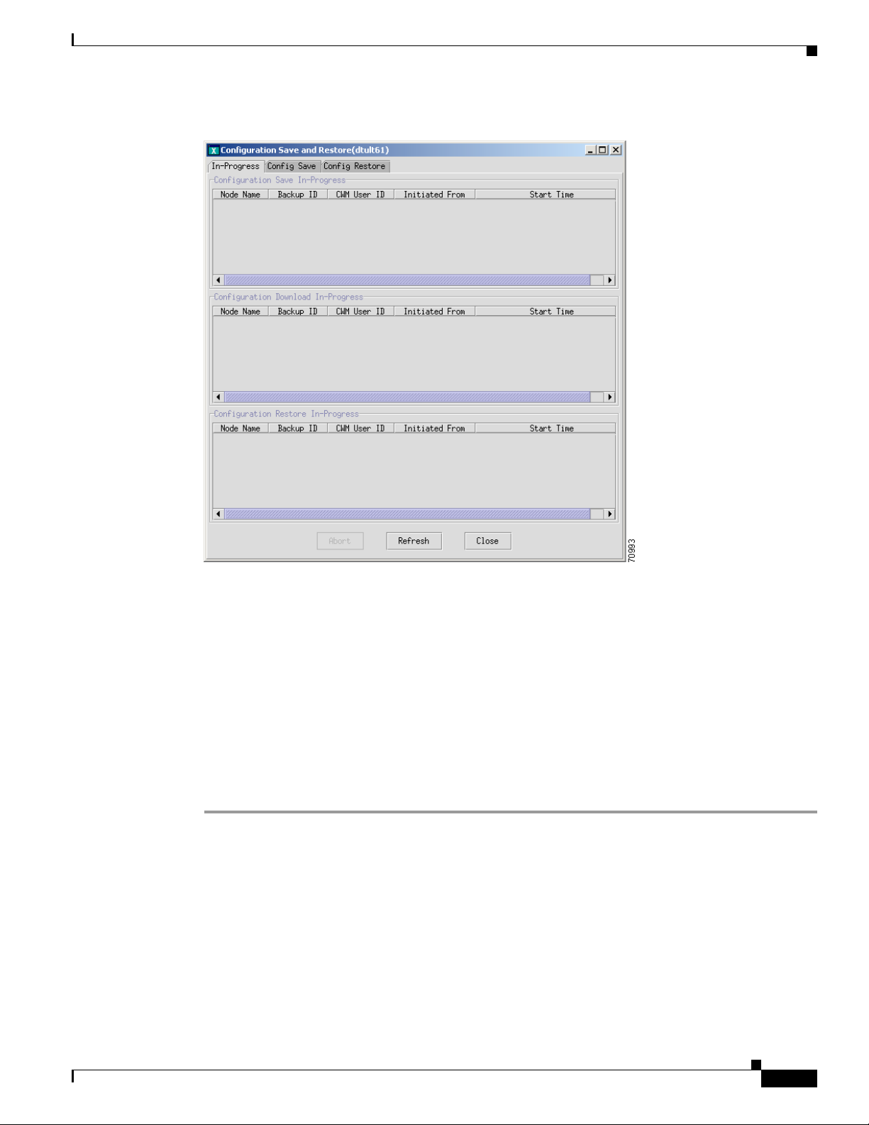
The Configuration Save and Restore: In-Progress window monitors the current save and restore
operations (see Figure 10-1).
10-2
Cisco WAN Manager User’s Guide
Release 15, Part Number OL-4552-01 Rev. C0, January 27, 2005
Page 3
Chapter 10 Cisco WAN Manager Operations
Figure 10-1 Configuration Save and Restore: In Progress Window
Saving and Restoring Configurations
Related Topics
• “Managing with the Configuration Save and Restore Utility” section on page 10-2
• “Saving Node Configurations from CWM” section on page 10-3
• “Restoring Node Configurations from CWM” section on page 10-10
• “Downloading Software and Firmware” section on page 10-12
Saving Node Configurations from CWM
To save node configurations, complete the following procedure:
Step 1 Click the In-Progress tab to verify that there is no save and restore operation currently in progress.
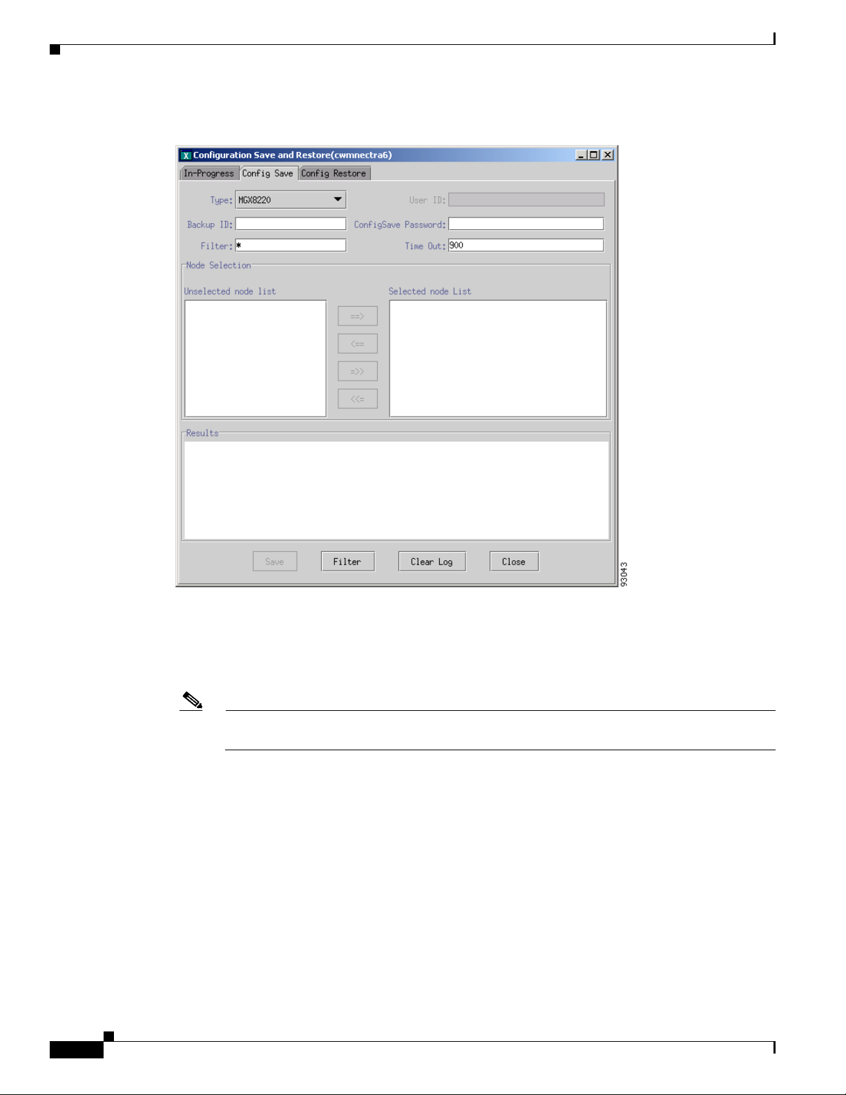
Step 2 Click the Config Save tab.
Figure 10-2 displays the Configuration Save window.
Release 15, Part Number OL-4552-01 Rev. C0, January 27, 2005
Cisco WAN Manager User’s Guide
10-3
Page 4
Saving and Restoring Configurations
Figure 10-2 Configuration Save Window
Chapter 10 Cisco WAN Manager Operations
Step 3
Step 4 Enter the backup ID in the Backup field. The backup ID is used as part of the filename that is created
Choose the node type from the Typ e drop-down arrow.
and stored in CWM. The maximum number of characters is less than 255. You must follow the UNIX
filename limitation rule.
Note For Cisco BPX 8600 and Cisco IGX 8400 series nodes, the maximum number of characters is
eight.
Step 5 Depending upon the node type, enter a username in the User ID field.
The Save button is greyed out until a username and password are entered.
The PXM1-based switches (Cisco MGX 8230, Cisco MGX 8250, and PXM1-based
Cisco MGX 8850) use TFTP to upload and download configurations. You must enter the correct
username in the User ID field.
When you are managing your configuration files for any non-PXM1-based switches, you are required to
enter a valid username in the User ID field. For information about the access privileges for Configuration
Save and Restore, see Chapter 2, “Getting Started with Cisco WAN Manager.”
Step 6 Enter the password in the ConfigSave Password field.
10-4
Cisco WAN Manager User’s Guide
Release 15, Part Number OL-4552-01 Rev. C0, January 27, 2005
Page 5

Chapter 10 Cisco WAN Manager Operations
The PXM1-based switches (Cisco MGX 8230, Cisco MGX 8250, and PXM1-based
Cisco MGX 8850) use TFTP to upload and download configurations. You must enter the correct
password in the ConfigSave Password field.
When you are managing your configuration files for any non-PXM1-based switches, you are required to
enter a valid password in the ConfigSave Password field that has sufficient privileges to be able to
execute a configuration save operation. For information about the access privileges for Configuration
Save and Restore, see Chapter 2, “Getting Started with Cisco WAN Manager.”
Step 7 Enter the timeout period in the Time Out field.
The timeout defines the period that CWM waits for the save operation to complete. Depending upon the
node type, the default is between 900 sec and 5400 sec.
Step 8 Select a node or nodes from the Unselected node list pane.
Step 9 Use the arrow keys to move the node or nodes over to the Selected node list pane.
Step 10 If there are too many nodes of the same type to select from, enter a character string that defines a subset
of the complete list for selection in the Filter field.
Step 11 Click Save to initiate the process.
You receive a confirmation message in the Results pane, which indicates whether the save operation is
initiated properly or not. After several minutes the system confirms a successful operation with the
following message:
Config Save...done
Saving and Restoring Configurations
Note Depending upon the node type and network load, the save process can take 10 to 20 min to
complete.
If you attempt to initiate a configuration save operation on a node that is already saving configurations
from a previous attempt, a message indicates that your request conflicts with another request.
For Cisco MGX nodes, you do not need to establish a telnet session for conflicting requests on the same
node.
For Cisco BPX and Cisco IGX nodes, if you have downloaded a configuration and executed a
configuration save immediately without executing the runcnf command first, you must:
• Right-click a node and choose Administration > Telnet to establish a telnet session with the node.
Or select a node from the Hierarchical Tree and choose Tools > Administration > Telnet.
• Enter the savecnf clear <nodename> <nodename> command to cancel the existing savecnf command
by executing the loadcnf clear command.
To cancel an existing save operation that originated from CWM:
• Click the In-Progress tab.
• Select the entry.
• Click Abort to cancel the save operation.
The files are saved to the usr/users/svplus/ConfigData/<backup ID>_<node name> directory.
For additional details, click the In-Progress tab to display an ongoing summary of the save operation.
Release 15, Part Number OL-4552-01 Rev. C0, January 27, 2005
Cisco WAN Manager User’s Guide
10-5
Page 6

Saving and Restoring Configurations
Note Cisco has various restore commands for the different switching platforms.
Related Topics
• “Saving and Restoring Configurations” section on page 10-1
• “Managing with the Configuration Save and Restore Utility” section on page 10-2
• “Launching the Configuration Save and Restore Utility” section on page 10-2
• “Saving Node Configurations for Cisco BPX and Cisco IGX Nodes” section on page 10-6
• “Restoring Node Configurations from CWM” section on page 10-10
• “Restoring Node Configurations for Cisco BPX or Cisco IGX Nodes” section on page 10-12
• “Downloading Software and Firmware” section on page 10-12
Saving Node Configurations for Cisco BPX and Cisco IGX Nodes
Chapter 10 Cisco WAN Manager Operations
You can save node configurations for Cisco BPX or Cisco IGX nodes.
The standard TFTP protocol backs up the Cisco BPX and Cisco IGX node configuration to a network
server other than CWM. The network server is any machine that is connected to a LAN attached to the
network, a TFTP server and disk, and stores configuration files. The configuration files are saved by
using the TFTP method and are restored by using the proprietary method, and so forth. The files are
stored in the correct directory with the correct filenames assumed by the proprietary protocol.
For more information about the TFTP Configuration Save and Restore facility and about the cnfswfunc
command, refer to the Cisco WAN Switching Command Reference, Release 9.3.30.
Note The CWM ConfigSave and Restore feature must be enabled on the BPX and IGX nodes. When this
option is not enabled, you can not save or restore the configuration from the node.
Procedure
To save a node configuration for Cisco BPX or Cisco IGX nodes, complete the following procedure:
Step 1 Open a terminal window.
Step 2 When you establish a CLI session, you must:
a. Enter the username at the prompt.
b. Enter the password at the prompt.
Step 3 Enter the cnfswfunc command to enable or verify the Configuration Save/Restore function for a
Cisco BPX node or Cisco IGX node.
Step 4 For the Cisco BPX node, enter index number 1 for the Configuration Save/Restore function.
For the Cisco IGX node, enter index number 4 for the
Configuration Save/Restore function.
10-6
Step 5 Enter e to enable the Configuration Save/Restore function for both the Cisco BPX and Cisco IGX nodes.
Note While executing the cnfswfunc command, you are prompted for a password.
Cisco WAN Manager User’s Guide
Release 15, Part Number OL-4552-01 Rev. C0, January 27, 2005
Page 7

Chapter 10 Cisco WAN Manager Operations
The following example shows that the Configuration Save/Restore function is enabled on the Cisco
BPX node:
node TN Cisco BPX 8620 9.4.00 Feb. 14 2003 16:36 GMT
Status Function
Index
1 Enabled Configuration Save/Restore
2 Enabled ForeSight
3 Disabled Multiple VTs (1 session enabled)
4 Disabled Virtual Trunks
5 Enabled ABR standard with VSVD
6 Disabled Priority Bumping
7 Disabled Virtual Ports
This Command: cnfswfunc 1 e
The output of cnfswfunc command is different on an Cisco IGX 8400 series switch. The following
example shows that the Configuration Save/Restore function is enabled on the Cisco IPX node:
node TN Cisco IGX 8430 9.4.00 Feb. 14 2003 17:27 GMT
Saving and Restoring Configurations
Status Function
Index
1 Disabled Repetitive Pattern Suppression
3 Enabled Frame Relay
4 Enabled Configuration Save/Restore
5 Disabled ForeSight
6 Disabled Frame Relay Network-to-Network Interface
7 Disabled Multiple VTs (1 session enabled)
8 Disabled Interface Shelf
9 Enabled Virtual Trunks
10 Disabled ABR standard with VSVD
This Command: cnfswfunc 4 e
Next Command:
Step 6 Enter the dspcnf command to check whether a firmware image is loaded on the node. When a a firmware
image is loaded on the node, the following message appears in the status column from the dspcnf
command:
Reserved for firmware image
The following example is displays the results from the dspcnf command:
bpx1 TN Cisco BPX 8620 9.3.h1 Mar. 9 2001 15:16 GMT
Node Backup ID Revision Date/Time (GMT) Status
-------- --------- -------- ----------------- --------------------------------bpx1 cisco111 9.3.h1 03/08/01 23:32:16 Save on 172.29.10.72 complete
sw200 Reserved for firmware image
sw76 cisco111 9.3.j3 03/08/01 23:32:16 Save on 172.29.10.72 complete
magneto cisco111 9.3.h1 03/08/01 23:32:16 Save on 172.29.10.72 complete
Last Command: dspcnf
Next Command:
Step 7 Enter the savecnf command to use the same buffers that are used by a loaded firmware image. Therefore,
when a firmware image is loaded on the node, the savecnf command displays an error.
Release 15, Part Number OL-4552-01 Rev. C0, January 27, 2005
Cisco WAN Manager User’s Guide
10-7
Page 8

Saving and Restoring Configurations
Note The two prerequisites for Cisco BPX and Cisco IGX nodes are that Configuration Save and
Step 8 Enter the getfwrev <card_type> 0.0 <node> command on the node to remove the loaded firmware
image. Specify 0.0 as the firmware revision level.
Chapter 10 Cisco WAN Manager Operations
Restore function is enabled, and the temporary memory is not used by the firmware image.
Replace <
Replace <
Note Before using the savecnf command, you must clean up the loaded firmware images.
Step 9 Enter the savecnf [backup_id | clear] [nodename | *] [CWM_nodename | *] <destination IP> <T>
<
pathname> command to save the node configuration and to upload the files to a CWM or a TFTP
card_type> with the card to load the revision.
node> with the node to load the revision.
network server where they are stored on disk.
The following example is shown:
bpx1 TN Cisco BPX 8620 9.3.h1 Mar. 9 2001 15:16 GMT
Node Backup ID Revision Date/Time (GMT) Status
-------- --------- -------- ----------------- --------------------------------nmsbpx14 C051598 9.3.h1 03/08/01 23:32:16 Saving on SV+ at nmsbpx14
nmssigx28 Reserved for firmware image
nmssigx27 C051598 9.3.h1 03/08/01 23:32:16 Save on SV+ at nmssigx27 complete
nmsbpx13 Clear
nmsbpx12 Save/Restore feature unavailable
Last Command: savecnf C051598 nmsbpx14 nmsbpx14 172.29.23.25
Next Command:
Table 10-1 lists the parameter definitions for the savecnf command.
Table 10-1 savecnf Command Parameter Definitions
10-8
Name Description
backup ID Specifies the partial name to identify the configuration file to be saved. The name
must be 1-8 alphanumeric characters, and the first character must be alphabetic.
Configuration names are case-sensitive.
clear Specifies an optional parameter that clears the buffer space in RAM of any old
configuration files before the new configuration snapshot is taken.
Note You must explicitly clear the buffer before it is loaded with a new file.
nodename Specifies the name of the node that needs to have the configuration saved. The
wildcard option, specified by an asterisk (*), is used in place of nodename to
indicate all nodes are to have their configuration saved.
A directory with the name /usr/users/svplus/<backup_id>_Cfgdir is created under
/usr/users/svplus/ConfigData/<backup_id>_Nodename directory.
Cisco WAN Manager User’s Guide
Release 15, Part Number OL-4552-01 Rev. C0, January 27, 2005
Page 9

Chapter 10 Cisco WAN Manager Operations
Table 10-1 savecnf Command Parameter Definitions (continued)
Name Description
CWM nodename Specifies the name of the node that has the CWM attached. The node name identifies
Saving and Restoring Configurations
the gateway node of the destination CWM for the configuration save. As an option,
an asterisk (*) indicates that the CWM IP address identifies the destination CWM.
Note The value for <CWM nodename> parameter is dependent on the configuration
in network.conf file of CWM.
When the last field in a /usr/users/svplus/network.conf file entry is set to
the <
CWM nodename> parameter is the same node where the savecnf command is
executed. For example, where <
node where the savecnf command is being run is also
CWM nodename> is specified as nmsbpx14 and the
nmsbpx14.
When the last field in a /usr/users/svplus/network.conf file entry is set to
the <
CWM nodename> parameter is the gateway node name. The gateway node name
nwip_on,
nwip_off,
is specified as the third field in a /usr/users/svplus/network.conf file entry of CWM.
For example, the savecnf command saves the configuration of node
CWM workstation, where the IP address is
gateway node
nmsbpx13.
172.29.23.25, and is connected to the
nmsbpx14 on the
The following example is shown:
Last Command: savecnf C051598 nmsbpx14 nmsbpx13 172.29.23.25
destination IP Specifies an optional parameter for the IP address of the CWM or TFTP network
server that is used as the source for the configuration restore.
Note This parameter is when an asterisk (*) is entered for CWM Nodename.
When more than two CWM workstations are connected to the network, you specify
the <
destination IP> parameter that identifies the CWM workstation where the
configuration save is done.
Note You cannot invoke a save configuration of all nodes by specifying an “*”
(asterisk) as the third parameter to the savecnf command when
nwip_on is
configured in the /usr/users/svplus/network.conf file.
T Specifies an optional parameter for TFTP that is used for data transfer instead of the
CWM proprietary protocol.
pathname Specifies a new optional parameter that is configured when TFTP is being used for
data transfer. The directory path name indicates where the backup files are stored.
Step 10 Save the configuration of all routing nodes when nwip_off is configured in the
/usr/users/svplus/network.conf file.
The following example shows that the configuration is saved for all routing nodes on the CWM
workstation with the
172.29.23.25 IP address, and the CWM gateway node is specified as nmsbpx13.
The configuration is saved in the /usr/users/svplus/C051598_Cfgdir directory.
Last Command: savecnf C051598 * nmsbpx13 172.29.23.25
Next Command:
Release 15, Part Number OL-4552-01 Rev. C0, January 27, 2005
Cisco WAN Manager User’s Guide
10-9
Page 10

Saving and Restoring Configurations
Related Topics
• “Saving and Restoring Configurations” section on page 10-1
• “Managing with the Configuration Save and Restore Utility” section on page 10-2
• “Launching the Configuration Save and Restore Utility” section on page 10-2
• “Saving Node Configurations from CWM” section on page 10-3
• “Restoring Node Configurations from CWM” section on page 10-10
• “Downloading Software and Firmware” section on page 10-12
Restoring Node Configurations from CWM
You can restore node configurations that are used to transfer the configuration data file to the switch and
to restore all of the configurations that are based on the data.
Procedure
To restore node configurations, complete the following procedure:
Chapter 10 Cisco WAN Manager Operations
Step 1 Click the In-Progress tab to verify that there is no save or restore operation currently in progress.
Step 2 Click the Config Restore tab.
Figure 10-3 displays the Configuration Restore window.
10-10
Cisco WAN Manager User’s Guide
Release 15, Part Number OL-4552-01 Rev. C0, January 27, 2005
Page 11

Chapter 10 Cisco WAN Manager Operations
Figure 10-3 Configuration Restore window
Saving and Restoring Configurations
Step 3
Step 4 Click Search to display the choices from the backup ID list.
Enter the name of the node in the Node Name field.
You can restrict the backup IDs that are displayed by using the Backup ID Filter option.
Step 5 Choose the backup ID from the Backup ID List pane.
Step 6 Depending upon the node type, enter a username in the User ID field.
The Restore button is greyed out until a username and password are entered.
The PXM1-based switches (Cisco MGX 8230, Cisco MGX 8250, and PXM1-based
Cisco MGX 8850) use TFTP to upload and download configurations. You must enter the correct
username in the User ID field.
When you are managing your configuration files for any non-PXM1-based switches, you are required to
enter a valid username in the User ID field.
Step 7 Enter the password in the Password field.
The PXM1-based switches (Cisco MGX 8230, Cisco MGX 8250, and PXM1-based
Cisco MGX 8850) use TFTP to upload and download configurations. You must enter the correct
password in the Password field.
When you are managing your configuration files for any non-PXM1-based switches, you are required to
enter a valid password in the Password field that has sufficient privileges to be able to execute a
configuration restore operation. For information about the access privileges for Configuration Save and
Restore, see Chapter 2, “Getting Started with Cisco WAN Manager.”
Release 15, Part Number OL-4552-01 Rev. C0, January 27, 2005
Cisco WAN Manager User’s Guide
10-11
Page 12

Downloading Software and Firmware
Step 8 Enter the timeout period in the Time Out field.
The timeout defines the period that CWM waits for the save operation to complete. Depending upon the
node type, the default is between 900 sec and 5400 sec.
Step 9 Click Restore to initiate the download of the selected configuration file to the target node.
Step 10 Monitor the restore process from the Results pane. A successful restore is confirmed by the following
message in the Results pane:
Config Restore...done
Related Topics
• “Saving and Restoring Configurations” section on page 10-1
• “Managing with the Configuration Save and Restore Utility” section on page 10-2
• “Launching the Configuration Save and Restore Utility” section on page 10-2
• “Saving Node Configurations from CWM” section on page 10-3
• “Saving Node Configurations for Cisco BPX and Cisco IGX Nodes” section on page 10-6
Chapter 10 Cisco WAN Manager Operations
• “Restoring Node Configurations for Cisco BPX or Cisco IGX Nodes” section on page 10-12
• “Downloading Software and Firmware” section on page 10-12
Restoring Node Configurations for Cisco BPX or Cisco IGX Nodes
To restore the node configuration for Cisco BPX or Cisco IGX nodes, use the restorecnf command. For
more information about the restorecnf command and other related commands, refer to the Cisco WAN
Switching Command Reference, Release 9.3.30.
Related Topics
• “Saving and Restoring Configurations” section on page 10-1
• “Managing with the Configuration Save and Restore Utility” section on page 10-2
• “Launching the Configuration Save and Restore Utility” section on page 10-2
• “Saving Node Configurations from CWM” section on page 10-3
• “Saving Node Configurations for Cisco BPX and Cisco IGX Nodes” section on page 10-6
• “Restoring Node Configurations from CWM” section on page 10-10
• “Downloading Software and Firmware” section on page 10-12
Downloading Software and Firmware
10-12
These tasks are used to download and upgrade software and firmware from the CWM workstation to a
Cisco WAN switch:
• Locating Switch Images for Downloading
• Preparing the Cisco BPX and Cisco IGX Switch to Download Software or Firmware
• Image Filename Conventions
• Managing with the Image Download
Cisco WAN Manager User’s Guide
Release 15, Part Number OL-4552-01 Rev. C0, January 27, 2005
Page 13

Chapter 10 Cisco WAN Manager Operations
Cisco IGX and Cisco BPX nodes maintain the primary version of the network operating software in
RAM of the active controller card. If redundant controllers are installed, the standby controller maintains
a secondary version, which may or may not be the same release level as the primary. The primary version
of the operating software can typically be the same release level on all nodes in the network.
All Cisco IGX and Cisco BPX card modules also have card and version specific firmware, which is
stored in flash memory on the front card. If applicable, firmware upgrades are downloaded to the switch
controller card, and distributed to the other cards within that switch. Cisco IGX and Cisco BPX nodes
do not provide long-term storage of firmware images on the controller card.
Cisco MGX nodes do not use network-switching software as on the Cisco IGX and Cisco BPX nodes.
The Cisco MGX nodes use firmware that controls shelf and card operation. The Cisco MGX controller
retains a copy of firmware for service modules, and upgrades are downloaded from a management
station.
The TFTP/FTP protocol downloads software and firmware images from the CWM workstation to WAN
switches.
The CWM Image Download downloads software and firmware images, and monitors the download
process.
Downloading Software and Firmware
Note A CWM workstation is not required to download the software images. You can download the software
images using any machine that can run a FTP client/server process.
Locating Switch Images for Downloading
Cisco Connection Online (CCO) provides a web page, WAN Switching Upgrade Planner, which provides
information about the latest Cisco software product. If you have a Cisco Connection Online account, you
can order or download software directly to your system. The URL for CCO software and firmware is
located at
The WAN Switching Upgrade Planner web page provides the following links:
• Product Information for WAN Switching Products
• Release Information for WAN Switching Products
• Documentation and Release Notes
• Previous Software for WAN Switching Products
• Downloading Cisco WAN Switching Software
• Downloading Cisco WAN Card Firmware
Related Topics
• “Managing with the Configuration Save and Restore Utility” section on page 10-2
http://www.cisco.com/kobayashi/sw-center/wan/wan-planner.shtml.
• “Downloading Software and Firmware” section on page 10-12
• “Preparing the Cisco BPX and Cisco IGX Switch to Download Software or Firmware” section on
page 10-14
• “Downloading Switch Software or Firmware from the CWM Workstation to a Switch” section on
page 10-18
• “Cisco IGX and Cisco BPX Conventions” section on page 10-19
• “Cisco MGX Conventions” section on page 10-19
Release 15, Part Number OL-4552-01 Rev. C0, January 27, 2005
Cisco WAN Manager User’s Guide
10-13
Page 14

Chapter 10 Cisco WAN Manager Operations
Downloading Software and Firmware
• “Managing with the Image Download” section on page 10-20
• “Deleting Images” section on page 10-24
Preparing the Cisco BPX and Cisco IGX Switch to Download Software or Firmware
To prepare the Cisco BPX and Cisco IGX switch to download software or firmware, complete the
following procedure:
Note This procedure is applicable only to Cisco IGX and Cisco BPX switches and is required regardless of
how the software image transfer is initiated.
Step 1 Access the switch CLI by attaching a dumb terminal to the switch or telnet to the switch.
Right-click a Cisco IGX or Cisco BPX node from the CWM application window and choose
Administration > Teln et to telnet to the switch. A terminal window is displayed.
Step 2 When you establish a CLI session, you must:
a. Enter the username at the prompt.
b. Enter the password at the prompt.
Step 3 Enter the cnffunc command to enable the switch for downloading.
Step 4 For a Cisco BPX node, enter index value 6 for the Download From Remote Cisco StrataView Plus
function.
For a Cisco IGX node, enter index value
Step 5 For a Cisco BPX node, enter e to enable the Download From Remote Cisco StrataView Plus function.
For a Cisco IGX node, enter e to enable the
8 for the Download From Remote CWM function.
Download From Remote CWM function.
Once the cnffunc command is executed, the switch allows downloading from a CWM workstation,
provided the latter is connected to another switch in the same network.
The following example is used for the Cisco BPX node:
node TN Cisco BPX 8620 9.4.00 Feb. 14 2003 16:36 GMT
Index Status Function
1 Enabled Automatic TRK Loopback Test on Local/Remote Alarms
2 Enabled User Command Logging
3 Enabled Automatic Card Reset on Hardware Error
4 Enabled Card Error Record Wraparound
5 Disabled Card Test After Failure
6 Enabled Download From Remote Cisco StrataView Plus
7 Disabled Logging of conn events in local event log
8 Disabled Logging of conn events in Cisco StrataView Plus event log
9 Disabled Force Download From a Specific IP address
10-14
This Command: cnffunc 6 e
Next Command:
Cisco WAN Manager User’s Guide
Release 15, Part Number OL-4552-01 Rev. C0, January 27, 2005
Page 15

Chapter 10 Cisco WAN Manager Operations
The following example is used for the Cisco IGX node:
node TN Cisco IGX 8430 9.4.00 Feb. 14 2003 17:27 GMT
Status Function
Index
1 Enabled Automatic CLN/PLN Loopback Test on Local/Remote Alarms
2 Enabled FDP Loopback button
3 Enabled User Command Logging
4 Enabled Automatic Card Reset on Hardware Error
5 Enabled TXR Model D Download
6 Enabled Card Error Record Wraparound
7 Disabled Card Test After Failure
8 Enabled Download From Remote CWM
9 Disabled Logging of conn events in local event log
10 Disabled Logging of conn events in CWM event log
11 Disabled Logging SVC Connection Events
12 Disabled Force Download From a Specific IP address
13 Disabled CDP WinkStart Signalling
14 Enabled Logging of Bus Diagnostic Events in local event log
15 Enabled Automatic Card Reset after Burnfw for CBI cards
16 Disabled Logging of router state events in CWM event log
This Command: cnffunc 8 e
Downloading Software and Firmware
Next Command:
Step 6 Enter the cnfnodeparm command when a redundant processor card is not installed.
Press Return to continue.
Step 7 For the Cisco BPX node, enter the parameter index 15 for the CC Redundancy Cnfged entry.
For the Cisco IGX node, enter the parameter index 16 for the
CC Redundancy Cnfged entry.
Step 8 When a redundant processor card (BCC, NPM, or NPC) is not installed, enter N to set the parameter that
indicates the presence of a redundant processor to No for both the Cisco BPX and Cisco IGX nodes.
The following example is used for the Cisco BPX node:
node TN Cisco BPX 8620 9.4.00 Feb. 14 2003 16:36 GMT
1 Update Initial Delay [ 5000] (D) 16 Stats Memory (x 100KB) [ 132] (D)
2 Update Per-Node Delay [30000] (D) 17 Standby Update Timer [ 10] (D)
3 Comm-Break Test Delay [30000] (D) 18 Stby Updts Per Pass [ 150] (D)
4 Comm-Break Test Offset [ 10] (D) 19 Gateway ID Timer [ 30] (D)
5 Network Timeout Period [ 1700] (D) 20 GLCON Alloc Timer [ 30] (D)
6 Network Inter-p Period [ 4000] (D) 21 Comm Fail Delay [ 60] (D)
7 NW Sliding Window Size [ 1] (D) 22 Nw Hdlr Timer (msec) [ 50] (D)
8 Num Normal Timeouts [ 7] (D) 23 SAR CC Transmit Rate [ 560] (D)
9 Num Inter-p Timeouts [ 3] (D) 24 SAR High Transmit Rate [ 280] (D)
10 Num Satellite Timeouts [ 6] (D) 25 SAR Low Transmit Rate [ 56] (D)
11 Num Blind Timeouts [ 4] (D) 26 SAR VRAM Cngestn Limit [ 7680] (D)
12 Num CB Msg Timeouts [ 5] (D) 27 SAR VRAM Cell Discard [ 256] (D)
13 Comm Fail Interval [10000] (D) 28 ASM Card Cnfged [ Y] (Y/N)
14 Comm Fail Multiplier [ 3] (D) 29 TFTP Grant Delay (sec) [ 1] (D)
15 CC Redundancy Cnfged [ Y] (Y/N) 30 TFTP ACK Timeout (sec) [ 10] (D)
31 TFTP Write Retries [ 3] (D) 46 Max Htls Rebuild Count [ 100] (D)
32 SNMP Event logging [ Y] (Y/N) 47 Htls Counter Reset Time[ 1000] (D)
33 Job Lock Timeout [ 60] (D) 48 Send Abit early [ N] (Y/N)
34 Max Via LCONs [50000] (D) 49 Abit Tmr Multiplier M [ 0] (D)
35 Max Blind Segment Size [ 3570] (D) 50 Abit Tmr Granularity N [ 3] (D)
36 Max XmtMemBlks per NIB [ 3000] (D) 51 FBTC with PPDPolicing [ N] (Y/N)
37 Max Mem on Stby Q (%) [ 33] (D) 52 CommBrk Hop Weight [ 25] (D)
38 Stat Config Proc Cnt [ 1000] (D) 53 CB Fail Penalty Hops [ 2] (D)
39 Stat Config Proc Delay [ 2000] (D) 54 Auto BXM upgrade [ Y] (Y/N)
Release 15, Part Number OL-4552-01 Rev. C0, January 27, 2005
Cisco WAN Manager User’s Guide
10-15
Page 16

Downloading Software and Firmware
40 Enable Degraded Mode [ Y] (Y/N) 55 LCN reprgrm batch cnt [ 100] (D)
41 Trk Cell Rtng Restrict [ Y] (Y/N) 56 Dnld LanIP or NwIP [ Nw](Lan/Nw)
42 Enable Feeder Alert [ N] (Y/N) 57 IP Relay gateway node [ 0] (D)
43 Reroute on Comm Fail [ N] (Y/N) 58 Max LAN Window (sec) [ 60] (D)
44 Auto Switch on Degrade [ Y] (Y/N) 59 Max LAN Packets/Window [18000] (D)
45 Max Degraded Aborts [ 100] (D) 60 Extended Cline Object [ N] (Y/N)
This Command: cnfnodeparm 15 N
Next Command:
The following example is used for a Cisco IGX node:
node TN Cisco IGX 8430 9.4.00 Feb. 14 2003 17:27 GMT
1 Update Initial Delay [ 5000] (D) 16 CC Redundancy Cnfged [ Y] (Y/N)
2 Update Per-Node Delay [30000] (D) 17 MT3 Pass Through Relay [ Y] (Y/N)
3 Comm-Break Test Delay [30000] (D) 18 Nw Pkt Tx Rate (pps) [ 500] (D)
4 Comm-Break Test Offset [ 10] (D) 19 Stats Memory (x 100KB) [ 130] (D)
5 Network Timeout Period [ 1700] (D) 20 Standby Update Timer [ 10] (D)
6 Network Inter-p Period [ 4000] (D) 21 Stby Updts Per Pass [ 150] (D)
7 NW Sliding Window Size [ 1] (D) 22 Gateway ID Timer [ 30] (D)
8 Num Normal Timeouts [ 7] (D) 23 GLCON Alloc Timer [ 30] (D)
9 Num Inter-p Timeouts [ 3] (D) 24 Comm Fail Delay [ 60] (D)
10 Num Satellite Timeouts [ 6] (D) 25 Nw Hdlr Timer (msec) [ 100] (D)
11 Num Blind Timeouts [ 4] (D) 26 CBUS Delay (msec) [ 20] (D)
12 Num CB Msg Timeouts [ 2] (D) 27 SNMP Event logging [ Y] (Y/N)
13 Comm Fail Interval [10000] (D) 28 TFTP Grant Delay (sec) [ 1] (D)
14 Comm Fail Multiplier [ 3] (D) 29 TFTP ACK Timeout (sec) [ 10] (D)
15 Temperature Threshold [ 50] (D) 30 TFTP Write Retries [ 3] (D)
31 FRP Link Status Alarm [ Y] (Y/N) 46 Modem polling timer [ 1] (D)
32 Job Lock Timeout [ 60] (D) 47 Verify CBA for non-FRP [ N] (Y/N)
33 Max Via LCONs [20000] (D) 48 Send Abit early [ N] (Y/N)
34 Max Blind Segment Size [ 3570] (D) 49 Abit Tmr Multiplier M [ 0] (D)
35 Max XmtMemBlks per NIB [ 3000] (D) 50 Abit Tmr Granularity N [ 3] (D)
36 Max Mem on Stby Q (%) [ 33] (D) 51 CommBrk Hop Weight [ 25] (D)
37 Trk Cell Rtng Restrict [ Y] (Y/N) 52 CB Fail Penalty Hops [ 2] (D)
38 Stat Config Proc Cnt [ 1000] (D) 53 Dnld LanIP or NwIP [ Lan](Lan/Nw)
39 Stat Config Proc Delay [ 2000] (D) 54 IP Relay gateway node [ 0] (D)
40 Enable Degraded Mode [ Y] (Y/N) 55 Max LAN Window (sec) [ 60] (D)
41 Enable Rrt on Comm Fail[ N] (Y/N) 56 Max LAN Packets/Window [18000] (D)
42 Auto Switch on Degrade [ Y] (Y/N)
43 Max Degraded Aborts [ 100] (D)
44 Max Htls Rebuild Count [ 100] (D)
45 Htls Counter Reset Time[ 1000] (D)
This Command: cnfnodeparm 16 N
Chapter 10 Cisco WAN Manager Operations
10-16
Next Command:
When you have a redundant processor card and the value for the parameter CC Redundancy Cnfged is
Yes, you are requesting an image download into both processors (active and redundant).
Note If CC Redundancy Cnfged is Yes and no redundant processor card is present, the download is
suspended.
Step 9 Enter the cnffwswinit <IP_addr_CWM_workstation> command to configure the switch to receive
software or firmware images from the CWM workstation.
Cisco WAN Manager User’s Guide
Release 15, Part Number OL-4552-01 Rev. C0, January 27, 2005
Page 17

Chapter 10 Cisco WAN Manager Operations
Replace the <IP_addr_CWM_workstation> parameter with the IP address of the CWM machine that
initiates a firmware or software download.
Note This is required if you are using a CWM workstation to send the download request to the switch.
The following example is shown for a Cisco BPX node:
This Command: cnffwswinit
Enter FW/SW Initiator SV+ IP addr(192.0.0.0):
Related Topics
• “Managing with the Configuration Save and Restore Utility” section on page 10-2
• “Downloading Software and Firmware” section on page 10-12
• “Monitoring a Download Session on Cisco BPX and Cisco IGX Nodes” section on page 10-17
• “Downloading Switch Software or Firmware from the CWM Workstation to a Switch” section on
page 10-18
Downloading Software and Firmware
• “Cisco IGX and Cisco BPX Conventions” section on page 10-19
• “Cisco MGX Conventions” section on page 10-19
• “Managing with the Image Download” section on page 10-20
• “Deleting Images” section on page 10-24
Monitoring a Download Session on Cisco BPX and Cisco IGX Nodes
The dsprevs (software) command and dspfwrev (firmware) command display existing software (or
firmware) revisions on a routing network, as well as the revisions currently being downloaded. When
these commands are issued at a feeder, revisions on that feeder alone appear on the screen.
You can use the dsprevs command or dspfwrev command to see when downloading of the software or
firmware is complete.
Related Topics
• “Managing with the Configuration Save and Restore Utility” section on page 10-2
• “Downloading Software and Firmware” section on page 10-12
• “Preparing the Cisco BPX and Cisco IGX Switch to Download Software or Firmware” section on
page 10-14
• “Downloading Switch Software or Firmware from the CWM Workstation to a Switch” section on
page 10-18
• “Cisco IGX and Cisco BPX Conventions” section on page 10-19
• “Cisco MGX Conventions” section on page 10-19
• “Managing with the Image Download” section on page 10-20
• “Deleting Images” section on page 10-24
Release 15, Part Number OL-4552-01 Rev. C0, January 27, 2005
Cisco WAN Manager User’s Guide
10-17
Page 18

Chapter 10 Cisco WAN Manager Operations
Downloading Software and Firmware
Downloading Switch Software or Firmware from the CWM Workstation to a Switch
To download images to a Cisco MGX node, complete the following steps:
Step 1 To establish a telnet session with the node:
• Right-click a node and choose Administration > Telnet.
• Select a node from the Hierarchical Tree and choose Tools > Administration > Telnet.
Step 2 From the Telnet window:
• Enter cd C:/FW command to change to the node directory to verify the software and firmware
images are present on the node for any particular card.
• Enter the cp command to copy the images to one of the following CWM workstation directories:
–
Cisco IGX or Cisco BPX images: /usr/users/svplus/images/ipxbpx directory
–
For Cisco MGX images: /usr/users/svplus/images/mgx directory
By using a workstation with FTP client software, you can also transfer the switch images to the switch
directory.
Step 3 Launch the CWM desktop. For more information about launching the CWM desktop, see Chapter 2,
“Getting Started with Cisco WAN Manager.”
Step 4 Login as a user with All access privileges for Topology. The CWM Launch Center is displayed. You can
use any CWM application window to select the node for downloading the switch software and firmware.
Step 5 Click the node icon in the Network Monitor window where you want to download the switch software
and firmware images.
Step 6 Choose Tools > Administration > Image Download to display the Image DownLoader window (see
Figure 10-4).
The Image DownLoader window displays a list of the software that is loaded on the CWM workstation
in the /usr/users/svplus/images/ directory for the selected node type.
Step 7 Select the image you want to download.
Step 8 Click Download. Once the download commences, a message appears in the Results pane.
Step 9 Once the download is finished, complete the following steps to verify that the downloaded image is
present:
• Establish a telnet session to the node.
• Display the contents of the C:/FW directory.
Note For additional details pertaining to the switches, please refer to the appropriate Cisco switch
documentation.
10-18
Related Topics
• “Managing with the Configuration Save and Restore Utility” section on page 10-2
• “Downloading Software and Firmware” section on page 10-12
• “Preparing the Cisco BPX and Cisco IGX Switch to Download Software or Firmware” section on
page 10-14
Cisco WAN Manager User’s Guide
Release 15, Part Number OL-4552-01 Rev. C0, January 27, 2005
Page 19

Chapter 10 Cisco WAN Manager Operations
• “Monitoring a Download Session on Cisco BPX and Cisco IGX Nodes” section on page 10-17
• “Cisco IGX and Cisco BPX Conventions” section on page 10-19
• “Cisco MGX Conventions” section on page 10-19
• “Managing with the Image Download” section on page 10-20
• “Deleting Images” section on page 10-24
Image Filename Conventions
The naming conventions for the Cisco IGX, Cisco BPX, and Cisco MGX nodes are used for software
images.
Related Topics
• “Cisco IGX and Cisco BPX Conventions” section on page 10-19
• “Cisco MGX Conventions” section on page 10-19
• “Deleting Images” section on page 10-24
Downloading Software and Firmware
Cisco IGX and Cisco BPX Conventions
Cisco IGX and Cisco BPX software images have the following format, for example, Release 9.2.0:
<Release>.img
<9.2.0>.img
<9.2.0>.000
...
<9.2.0>.022
Cisco IGX and Cisco BPX firmware images have the following format:
<FW Release>.img
<A.A.02>.img
Related Topics
• “Image Filename Conventions” section on page 10-19
• “Cisco MGX Conventions” section on page 10-19
• “Deleting Images” section on page 10-24
Cisco MGX Conventions
The following naming convention is used for software images:
<cardtype>_<A>_<B> [<C>_<D>].fw
Replace <cardtype> with the name of the card.
<A>, <B>, <C>, and <D> is a string that contains any combination of numerals and characters.
<A>_<B> <C>_<D> indicates the firmware version number of a given image file. <C> and <D> are
optional. The .fw extension indicates the file is a firmware image.
Release 15, Part Number OL-4552-01 Rev. C0, January 27, 2005
Cisco WAN Manager User’s Guide
10-19
Page 20

Downloading Software and Firmware
Related Topics
• “Image Filename Conventions” section on page 10-19
• “Cisco IGX and Cisco BPX Conventions” section on page 10-19
• “Deleting Images” section on page 10-24
Managing with the Image Download
These tasks are used to manage the Image Download:
• Launching the Image Download
• Image Download Access Tabs
• Processing the Downloaded Image
Launching the Image Download
To launch the Image Download application, you can:
• Choose Tools > Administration > Image Download from any application.
• Right-click within any application and choose Administration > Image Download.
Chapter 10 Cisco WAN Manager Operations
Figure 10-4 displays the Image Download window.
Figure 10-4 In-Progress View
10-20
Cisco WAN Manager User’s Guide
Release 15, Part Number OL-4552-01 Rev. C0, January 27, 2005
Page 21

Chapter 10 Cisco WAN Manager Operations
Note CWM Image Download transfers only the image file from the CWM workstation to the switch.
Related Topics
• “Managing with the Image Download” section on page 10-20
• “Image Download Access Tabs” section on page 10-21
• “Processing the Downloaded Image” section on page 10-21
• “Deleting Images” section on page 10-24
Image Download Access Tabs
Table 10-2 describes the access tabs that you need for the image download process.
Table 10-2 Image Download Access Tabs
Access Tabs Task
In-Progress Contains information about the on-going image download processes
Image Download Downloads the chosen image(s) to the chosen switch(s).
Downloading Software and Firmware
Related Topics
• “Managing with the Image Download” section on page 10-20
• “Launching the Image Download” section on page 10-20
• “Processing the Downloaded Image” section on page 10-21
Processing the Downloaded Image
The downloaded image process is used to transfer the configuration data file from CWM workstation to
the switch.
Procedure
To process the downloaded image, complete the following procedure:
Step 1 Click the In-Progress tab to view the image download already in progress (see Figure 10-5).
Release 15, Part Number OL-4552-01 Rev. C0, January 27, 2005
Cisco WAN Manager User’s Guide
10-21
Page 22

Downloading Software and Firmware
Figure 10-5 Image Download In-Progress
Chapter 10 Cisco WAN Manager Operations
10-22
Step 2
Cisco WAN Manager User’s Guide
Click the Image Download tab to display the Image Download window (see Figure 10-6).
Release 15, Part Number OL-4552-01 Rev. C0, January 27, 2005
Page 23

Chapter 10 Cisco WAN Manager Operations
Figure 10-6 Image Download View
Downloading Software and Firmware
Step 3 Choose the node from the Type drop-down arrow that lists all of the available nodes for the selected
platform.
Step 4 Click ==> to move the chosen item(s) from the Unselected node list pane to the Selected node list pane.
Yo u can :
a. Click <== to deselect the highlighted item(s) from the Selected node list pane back to the
Unselected node list pane.
b. Click =>> to select ALL the items from the Unselected node list pane to the Selected node list
pane.
c. Click <<= to deselect ALL the items from the Selected node list pane back to the Unselected node
list pane.
Step 5 Choose the available image(s) from the Image List area.
Step 6 Click Download.
The chosen image(s) are downloaded to the switch node(s) that are listed in the Selected node list pane.
The result(s) are displayed at the Results area.
Note The message confirms only that the download request is received at the target switch; it does not
indicate that the process is continuing properly.
Step 7 Click Clear Log to clear the message(s) in the Result area.
Release 15, Part Number OL-4552-01 Rev. C0, January 27, 2005
Cisco WAN Manager User’s Guide
10-23
Page 24

Deleting Images
Related Topics
• “Managing with the Image Download” section on page 10-20
• “Launching the Image Download” section on page 10-20
• “Image Download Access Tabs” section on page 10-21
• “Deleting Images” section on page 10-24
Deleting Images
You can delete unwanted or obsolete software and firmware images from CWM.
Software and firmware images are deleted from the network management station for the following
reasons:
• After the network is upgraded
• After the network is determined to be stable
• If a corrupt version of software or firmware is detected
Chapter 10 Cisco WAN Manager Operations
Procedure
If the CWM disk space has reached capacity, complete the following procedure:
Step 1 Right-click the node within any CWM application window and choose Administration > Teln et to
telnet to the switch. A terminal window is displayed.
Step 2 When you establish a CLI session, you must:
a. Enter the username at the prompt.
b. Enter the password at the prompt.
Step 3 Enter the su command to become the superuser. The following example shows the login to the root
account:
tballraker18% su root
Password:
#
Step 4 Enter the cd command to change the directory to /usr/users/svplus/images/ipxbpx as shown in the
following example:
# cd /usr/users/svplus/images/ipxbpx
#
Step 5 Enter the rm command to remove the filename.
The following example shows the removal of the firmware revision file:
# rm -r 9103B.*
#
10-24
Related Topics
• “Saving and Restoring Configurations” section on page 10-1
• “Downloading Software and Firmware” section on page 10-12
Cisco WAN Manager User’s Guide
Release 15, Part Number OL-4552-01 Rev. C0, January 27, 2005
Page 25

Chapter 10 Cisco WAN Manager Operations
• “Locating Switch Images for Downloading” section on page 10-13
• “Preparing the Cisco BPX and Cisco IGX Switch to Download Software or Firmware” section on
page 10-14
Deleting Images
Release 15, Part Number OL-4552-01 Rev. C0, January 27, 2005
Cisco WAN Manager User’s Guide
10-25
Page 26

Deleting Images
Chapter 10 Cisco WAN Manager Operations
10-26
Cisco WAN Manager User’s Guide
Release 15, Part Number OL-4552-01 Rev. C0, January 27, 2005
 Loading...