

Page 1

Cisco 10000 Series Router Service Selection Gateway Configuration Guide
January 2004
Corporate Headquarters
Cisco Systems, Inc.
170 West Tasman Drive
San Jose, CA 95134-1706
USA
http://www.cisco.com
Tel: 408 526-4000
800 553-NETS (6387)
Fax: 408 526-4100
Text Part Number: OL-4387-02
Page 2

THE SPECIFICATIONS AND INFORMATION REGARDING THE PRODUCTS IN THIS MANUAL ARE SUBJECT TO CHANGE WITHOUT NOTICE. ALL
STATEMENTS, INFORMATION, AND RECOMMENDATIONS IN THIS MANUAL ARE BELIEVED TO BE ACCURATE BUT ARE PRESENTED WITHOUT
WARRANTY OF ANY KIND, EXPRESS OR IMPLIED. USERS MUST TAKE FULL RESPONSIBILITY FOR THEIR APPLICATION OF ANY PRODUCTS.
THE SOFTWARE LICENSE AND LIMITED WARRANTY FOR THE ACCOMPANYING PRODUCT ARE SET FORTH IN THE INFORMATION PACKET THAT
SHIPPED WITH THE PRODUCT AND ARE INCORPORATED HEREIN BY THIS REFERENCE. IF YOU ARE UNABLE TO LOCATE THE SOFTWARE LICENSE
OR LIMITED WARRANTY, CONTACT YOUR CISCO REPRESENTATIVE FOR A COPY.
The Cisco implementation of TCP header compression is an adaptation of a program developed by the University of California, Berkeley (UCB) as part of UCB’s public
domain version of the UNIX operating system. All rights reserved. Copyright © 1981, Regents of the University of California.
NOTWITHSTANDING ANY OTHER WARRANTY HEREIN, ALL DOCUMENT FILES AND SOFTWARE OF THESE SUPPLIERS ARE PROVIDED “AS IS” WITH
ALL FAULTS. CISCO AND THE ABOVE-NAMED SUPPLIERS DISCLAIM ALL WARRANTIES, EXPRESSED OR IMPLIED, INCLUDING, WITHOUT
LIMITATION, THOSE OF MERCHANTABILITY, FITNESS FOR A PARTICULAR PURPOSE AND NONINFRINGEMENT OR ARISING FROM A COURSE OF
DEALING, USAGE, OR TRADE PRACTICE.
IN NO EVENT SHALL CISCO OR ITS SUPPLIERS BE LIABLE FOR ANY INDIRECT, SPECIAL, CONSEQUENTIAL, OR INCIDENTAL DAMAGES, INCLUDING,
WITHOUT LIMITATION, LOST PROFITS OR LOSS OR DAMAGE TO DATA ARISING OUT OF THE USE OR INABILITY TO USE THIS MANUAL, EVEN IF CISCO
OR ITS SUPPLIERS HAVE BEEN ADVISED OF THE POSSIBILITY OF SUCH DAMAGES.
CCIP, CCSP, the Cisco Arrow logo, the Cisco Powered Network mark, Cisco Unity, Follow Me Browsing, FormShare, and StackWise are trademarks of Cisco Systems, Inc.;
Changing the Way We Work, Live, Play, and Learn, and iQuick Study are service marks of Cisco Systems, Inc.; and Aironet, ASIST, BPX, Catalyst, CCDA, CCDP, CCIE,
CCNA, CCNP, Cisco, the Cisco Certified Internetwork Expert logo, Cisco IOS, the Cisco IOS logo, Cisco Press, Cisco Systems, Cisco Systems Capital, the Cisco Systems
logo, Empowering the Internet Generation, Enterprise/Solver, EtherChannel, EtherSwitch, Fast Step, GigaStack, Internet Quotient, IOS, IP/TV, iQ Expertise, the iQ logo, iQ
Net Readiness Scorecard, LightStream, MGX, MICA, the Networkers logo, Networking Academy, Network Registrar, Packet, PIX, Post-Routing, Pre-Routing, RateMUX,
Registrar, ScriptShare, SlideCast, SMARTnet, StrataView Plus, Stratm, SwitchProbe, TeleRouter, The Fastest Way to Increase Your Internet Quotient, TransPath, and VCO
are registered trademarks of Cisco Systems, Inc. and/or its affiliates in the U.S. and certain other countries.
All other trademarks mentioned in this document or Web site are the property of their respective owners. The use of the word partner does not imply a partnership relationship
between Cisco and any other company. (0304R)
Cisco 10000 Series Router Service Selection Gateway Configuration Guide
Copyright ©2004, Cisco Systems, Inc.
All rights reserved.
Page 3
About This Guide ix
Audience ix
Document Organization ix
Document Conventions x
Related Documentation xi
Obtaining Documentation xi
Cisco.com xi
Documentation CD-ROM xii
Ordering Documentation xii
Documentation Feedback xii
Obtaining Technical Assistance xii
Cisco TAC Website xiii
Opening a TAC Case xiii
TAC Case Priority Definitions xiii
Obtaining Additional Publications and Information xiv
CONTENTS
CHAPTER
CHAPTER
CHAPTER
1 Service Selection Gateway Overview 1-1
Service Selection Gateway 1-1
Default Network 1-3
Access Protocols 1-3
Supported SSG Features 1-4
SSG Restrictions 1-4
SSG Prerequisites 1-6
SSG Architecture Model 1-6
2 Scalability and Performance 2-1
Limitations and Restrictions 2-1
3 SSG Logon and Logoff 3-1
Single Host Logon 3-1
Prerequisites for Single Host Logon 3-1
SSG Autologoff 3-2
Restrictions for SSG Autologoff 3-2
OL-4387-02
Cisco 10000 Series Router Service Selection Gateway Configuration Guide
iii
Page 4

Contents
Configuration of SSG Autologoff 3-2
Configuration Example for SSG Autologoff 3-3
SSG Prepaid Idle Timeout 3-3
Service Authorization 3-4
Service Reauthorization 3-4
Restrictions for SSG Prepaid Idle Timeout 3-5
Prerequisites for SSG Prepaid Idle Timeout 3-5
Configuration of SSG Prepaid Idle Timeout 3-5
Configuration Example for SSG Prepaid Idle Timeout 3-5
SSG Session and Idle Timeout 3-6
CHAPTER
CHAPTER
CHAPTER
4 Authentication and Accounting 4-1
SSG Full Username RADIUS Attribute 4-1
Restrictions for SSG Full Username RADIUS Attribute 4-1
Configuration Examples for SSG Full Username RADIUS Attribute 4-1
RADIUS Accounting Records 4-2
Account Login and Logout 4-2
Configuration Examples for Account Login and Logout 4-2
Service Connection and Termination 4-3
Configuration Examples for Service Connection and Termination 4-3
5 Service Selection Methods 5-1
PPP Terminated Aggregation 5-1
PTA-Multidomain 5-1
Restrictions for PTA-MD 5-2
Web Service Selection 5-2
SESM and SSG Performance 5-3
6 Service Connection 6-1
iv
SSG AutoDomain 6-1
Restrictions for SSG AutoDomain 6-2
Configuration of SSG AutoDomain 6-2
Configuration Example for SSG AutoDomain 6-2
SSG Prepaid 6-4
Restrictions for SSG Prepaid 6-4
Configuration of SSG Prepaid 6-4
Configuration Example for SSG Prepaid 6-5
SSG Open Garden 6-5
Cisco 10000 Series Router Service Selection Gateway Configuration Guide
OL-4387-02
Page 5
Restrictions for SSG Open Garden 6-6
Configuration of SSG Open Garden 6-6
Configuration Example for SSG Open Garden 6-6
SSG Port-Bundle Host Key 6-6
Restrictions for SSG Port-Bundle Host Key 6-7
Prerequisites for SSG Port-Bundle Host Key 6-8
Configuration of SSG Port-Bundle Host Key 6-8
Exclude Networks 6-8
Mutually Exclusive Service Selection 6-8
Configuration of Mutually Exclusive Service Selection 6-9
Configuration Example for Mutually Exclusive Service Selection 6-9
Contents
CHAPTER
7 Service Profiles and Cached Service Profiles 7-1
Service Profiles 7-1
Downstream Access Control List 7-1
Upstream Access Control List 7-2
Domain Name 7-2
Full Username 7-2
MTU Size 7-2
RADIUS Server 7-2
Service Authentication Type 7-2
Service-Defined Cookie 7-3
Service Description 7-3
Service Mode 7-3
Service Next-Hop Gateway 7-3
Service Route 7-3
Service URL 7-3
Type of Service 7-4
Service Profile Example 7-4
Cached Service Profiles 7-4
Configuration of Cached Service Profiles 7-5
CHAPTER
OL-4387-02
8 SSG Hierarchical Policing 8-1
SSG Hierarchical Policing Overview 8-1
SSG Hierarchical Policing Token Bucket Scheme 8-1
Restrictions for SSG Hierarchical Policing 8-2
SSG Hierarchical Policing Configuration 8-2
Configuration Examples for SSG Hierarchical Policing 8-3
Cisco 10000 Series Router Service Selection Gateway Configuration Guide
v
Page 6
Contents
CHAPTER
CHAPTER
9 Interface Configuration 9-1
Transparent Passthrough 9-1
Access Side Interfaces 9-2
Network Side Interfaces 9-3
Restrictions of Transparent Passthrough 9-3
Configuration of Transparent Passthrough 9-3
Multicast Protocols on SSG Interfaces 9-3
Configuration of Multicast Protocols on SSG Interfaces 9-4
10 SSG TCP Redirect 10-1
Redirection for Unauthenticated Users 10-1
Redirection for Unauthorized Services 10-2
Initial Captivation 10-3
Restrictions for SSG TCP Redirect 10-4
Prerequisites for SSG TCP Redirect 10-4
Configuration of SSG TCP Redirect 10-4
Configuration Considerations for SSG TCP Redirect 10-5
Configuring Port-Based Redirection for Unauthenticated Users 10-5
Limiting Redirection for Unauthenticated Users 10-5
Configuring SSG TCP Redirect 10-6
Configuration Examples for SSG TCP Redirect 10-7
Configuration Example for Server Groups 10-7
Configuration Example for Network Lists 10-7
Configuration Example for Port Lists 10-8
CHAPTER
vi
11 Miscellaneous SSG Features 11-1
VPI/VCI Static Binding to a Service Profile 11-1
Restrictions for VPI/VCI Static Binding to a Service Profile 11-1
Configuration of VPI/VCI Static Binding to a Service Profile 11-1
RADIUS Virtual Circuit Logging 11-2
Configuration of RADIUS Virtual Circuit Logging 11-2
AAA Server Group Support for Proxy Services 11-2
Restrictions for AAA Server Group Support for Proxy Services 11-2
Configuration of AAA Server Group Support for Proxy Services 11-3
Configuration Example for AAA Server Group Support for Proxy Services 11-3
Packet Filtering 11-3
Downstream Access Control List—outacl 11-4
Upstream Access Control List—inacl 11-4
Restrictions for Packet Filtering 11-4
Cisco 10000 Series Router Service Selection Gateway Configuration Guide
OL-4387-02
Page 7
Configuration of Packet Filtering 11-5
Configuration Example for Packet Filtering 11-5
SSG Unconfig 11-5
Restrictions for SSG Unconfig 11-5
Prerequisites for SSG Unconfig 11-6
Configuration of SSG Unconfig 11-6
Configuration Examples for SSG Unconfig 11-6
SSG Enhancements for Overlapping Services 11-7
Service Translation 11-7
Restrictions for Service Translation 11-9
Prerequisites for Service Translation 11-9
Configuration of Service Translation 11-10
Configuration Example for Service Translation 11-10
Expansion of Service IDs 11-11
Restrictions for Expansion of Service IDs 11-11
Configuration Example for Expansion of Service IDs 11-11
Contents
CHAPTER
APPENDIX
APPENDIX
G
LOSSARY
I
NDEX
12 Monitoring and Maintaining SSG 12-1
Troubleshooting RADIUS 12-2
Per-Service Statistics 12-2
Restrictions for Per-Service Statistics 12-2
Monitoring the Parallel Express Forwarding Engine 12-3
A SSG Configuration Example A-1
B SSG Implementation Notes B-1
OL-4387-02
Cisco 10000 Series Router Service Selection Gateway Configuration Guide
vii
Page 8

Contents
viii
Cisco 10000 Series Router Service Selection Gateway Configuration Guide
OL-4387-02
Page 9
About This Guide
This guide provides information about the Service Selection Gateway (SSG) features of the Cisco 10000
Series Router. The SSG features are supported in Cisco IOS Release 12.2(16)BX and later releases.
Audience
This guide is designed for system and network managers responsible for configuring Service Selection
Gateway features on the Cisco 10000 router. The manager should be experienced using Cisco IOS
software and be familiar with the operation of the Cisco 10000 router.
Document Organization
This guide contains the following chapters:
Chapter Title Description
Chapter 1 Service Selection Gateway Overview Describes the Service Selection Gateway features, restrictions,
and prerequisites. Also provides an architectural model.
Chapter 2 Scalability and Performance Describes limitations and restrictions, of the Service Selection
Gateway feature.
Chapter 3 SSG Logon and Logoff Describes the SSG features for logon and logoff related
functions.
Chapter 4 Authentication and Accounting Describes the SSG features for authentication and accounting
related functions.
Chapter 5 Service Selection Methods Describes the service selection methods supported on the
Cisco 10000 router.
Chapter 6 Service Connection Describes the SSG features for service connection.
Chapter 7 Service Profiles and Cached Service
Profiles
Chapter 8 SSG Hierarchical Policing Describes the SSG Hierarchical Policing feature supported by
Chapter 9 Interface Configuration Describes the Transparent Passthrough and Multicast Protocols
Describes service profiles and cached service profiles.
the Cisco 10000 router.
on SSG Interfaces features.
OL-4387-02
Cisco 10000 Series Router Service Selection Gateway Configuration Guide
ix
Page 10
About This Guide
Document Conventions
Chapter Title Description
Chapter 10 SSG TCP Redirect Describes the TCP Redirect feature for SSG.
Chapter 11 Miscellaneous SSG Features Describes the following features:
• VPI/VCI Static Binding to a Service Profile
• RADIUS Virtual Circuit Logging
• AAA Server Group Support for Proxy Services
• Packet Filtering
• SSG Unconfig
• SSG Enhancements for Overlapping Services
Chapter 12 Monitoring and Maintaining SSG Provides show commands for monitoring and maintaining
SSG, describes the per-service statistics feature, and provides
commands for monitoring the Parallel Express Forwarding
(PXF) engine.
Appendix A Configuration Example for SSG Provides a basic configuration example for SSG.
Note This guide also includes a glossary of terms used in the document and an index to help you locate topics.
Document Conventions
This guide uses the following conventions:
• Bold is used for commands, keywords, and buttons.
• Italics are used for command input for which you supply values.
• Screen font is used for examples of information that are displayed on the screen.
• Bold screen font is used for examples of information that you enter.
• Vertical bars ( | ) indicate separate alternative, mutually exclusive elements.
• Square brackets ( [ ] ) indicate optional elements.
• Braces ( {} ) indicate a required choice.
• Braces within square brackets ( [{}] ) indicate a required choice within an optional element.
Note Means reader take note. Notes contain helpful suggestions or references to material not covered in the
guide.
Timesaver Means the described action saves time. You can save time by performing the action described in the
paragraph.
Cisco 10000 Series Router Service Selection Gateway Configuration Guide
x
OL-4387-02
Page 11
About This Guide
Caution Means reader be careful. In this situation, you might do something that could result in equipment
Related Documentation
damage or loss of data.
Warning
Means
equipment, you must be aware of the hazards involved with electrical circuitry and familiar with
standard practices for preventing accidents. To see translated versions of warnings, refer to the
Regulatory Compliance and Safety Information
danger
. You are in a situation that could cause bodily injury. Before you work on any
Related Documentation
The following documentation provides additional information about the Cisco 10000 router and its
features:
• Cisco 10000 Series Router Feature Map
• Cisco 10000 Series Router Software Configuration Guides
• Cisco 10000 Series Router Hardware Documents
• Technology of Edge Aggregation: Cisco 10000 Series Router
• Cisco 10000 Series Router Technical Reference
• Cisco 10000 Series Router Useful Links
• Cisco 10000 Series Router MIB Documents
Obtaining Documentation
document that accompanied the device.
Cisco.com
OL-4387-02
Cisco provides several ways to obtain documentation, technical assistance, and other technical
resources. These sections explain how to obtain technical information from Cisco Systems.
You can access the most current Cisco documentation on the World Wide Web at this URL:
http://www.cisco.com/univercd/home/home.htm
You can access the Cisco website at this URL:
http://www.cisco.com
International Cisco websites can be accessed from this URL:
http://www.cisco.com/public/countries_languages.shtml
Cisco 10000 Series Router Service Selection Gateway Configuration Guide
xi
Page 12
Documentation Feedback
Documentation CD-ROM
Cisco documentation and additional literature are available in a Cisco Documentation CD-ROM
package, which may have shipped with your product. The Documentation CD-ROM is updated regularly
and may be more current than printed documentation. The CD-ROM package is available as a single unit
or through an annual or quarterly subscription.
Registered Cisco.com users can order a single Documentation CD-ROM (product number
DOC-CONDOCCD=) through the Cisco Ordering tool:
http://www.cisco.com/en/US/partner/ordering/ordering_place_order_ordering_tool_launch.html
All users can order annual or quarterly subscriptions through the online Subscription Store:
http://www.cisco.com/go/subscription
Click Subscriptions & Promotional Materials in the left navigation bar.
Ordering Documentation
You can find instructions for ordering documentation at this URL:
http://www.cisco.com/univercd/cc/td/doc/es_inpck/pdi.htm
About This Guide
You can order Cisco documentation in these ways:
• Registered Cisco.com users (Cisco direct customers) can order Cisco product documentation from
the Networking Products MarketPlace:
http://www.cisco.com/en/US/partner/ordering/index.shtml
• Nonregistered Cisco.com users can order documentation through a local account representative by
calling Cisco Systems Corporate Headquarters (California, USA) at 408 526-7208 or, elsewhere in
North America, by calling 800 553-NETS (6387).
Documentation Feedback
You can submit e-mail comments about technical documentation to bug-doc@cisco.com.
You can submit comments by using the response card (if present) behind the front cover of your
document or by writing to the following address:
Cisco Systems
Attn: Customer Document Ordering
170 West Tasman Drive
San Jose, CA 95134-9883
We appreciate your comments.
Obtaining Technical Assistance
For all customers, partners, resellers, and distributors who hold valid Cisco service contracts, the Cisco
Technical Assistance Center (TAC) provides 24-hour-a-day, award-winning technical support services,
online and over the phone. Cisco.com features the Cisco TAC website as an online starting point for
technical assistance. If you do not hold a valid Cisco service contract, please contact your reseller.
Cisco 10000 Series Router Service Selection Gateway Configuration Guide
xii
OL-4387-02
Page 13
About This Guide
Cisco TAC Website
The Cisco TAC website provides online documents and tools for troubleshooting and resolving technical
issues with Cisco products and technologies. The Cisco TAC website is available 24 hours a day, 365
days a year. The Cisco TAC website is located at this URL:
http://www.cisco.com/tac
Accessing all the tools on the Cisco TAC website requires a Cisco.com user ID and password. If you
have a valid service contract but do not have a login ID or password, register at this URL:
http://tools.cisco.com/RPF/register/register.do
Opening a TAC Case
Using the online TAC Case Open Tool is the fastest way to open P3 and P4 cases. (P3 and P4 cases are
those in which your network is minimally impaired or for which you require product information.) After
you describe your situation, the TAC Case Open Tool automatically recommends resources for an
immediate solution. If your issue is not resolved using the recommended resources, your case will be
assigned to a Cisco TAC engineer. The online TAC Case Open Tool is located at this URL:
Obtaining Technical Assistance
http://www.cisco.com/tac/caseopen
For P1 or P2 cases (P1 and P2 cases are those in which your production network is down or severely
degraded) or if you do not have Internet access, contact Cisco TAC by telephone. Cisco TAC engineers
are assigned immediately to P1 and P2 cases to help keep your business operations running smoothly.
To open a case by telephone, use one of the following numbers:
Asia-Pacific: +61 2 8446 7411 (Australia: 1 800 805 227)
EMEA: +32 2 704 55 55
USA: 1 800 553-2447
For a complete listing of Cisco TAC contacts, go to this URL:
http://www.cisco.com/warp/public/687/Directory/DirTAC.shtml
TAC Case Priority Definitions
To ensure that all cases are reported in a standard format, Cisco has established case priority definitions.
Priority 1 (P1)—Your network is “down” or there is a critical impact to your business operations. You
and Cisco will commit all necessary resources around the clock to resolve the situation.
Priority 2 (P2)—Operation of an existing network is severely degraded, or significant aspects of your
business operation are negatively affected by inadequate performance of Cisco products. You and Cisco
will commit full-time resources during normal business hours to resolve the situation.
Priority 3 (P3)—Operational performance of your network is impaired, but most business operations
remain functional. You and Cisco will commit resources during normal business hours to restore service
to satisfactory levels.
OL-4387-02
Priority 4 (P4)—You require information or assistance with Cisco product capabilities, installation, or
configuration. There is little or no effect on your business operations.
Cisco 10000 Series Router Service Selection Gateway Configuration Guide
xiii
Page 14

Obtaining Additional Publications and Information
Obtaining Additional Publications and Information
Information about Cisco products, technologies, and network solutions is available from various online
and printed sources.
• The Cisco Product Catalog describes the networking products offered by Cisco Systems, as well as
ordering and customer support services. Access the Cisco Product Catalog at this URL:
http://www.cisco.com/en/US/products/products_catalog_links_launch.html
• Cisco Press publishes a wide range of general networking, training and certification titles. Both new
and experienced users will benefit from these publications. For current Cisco Press titles and other
information, go to Cisco Press online at this URL:
http://www.ciscopress.com
• Packet magazine is the Cisco quarterly publication that provides the latest networking trends,
technology breakthroughs, and Cisco products and solutions to help industry professionals get the
most from their networking investment. Included are networking deployment and troubleshooting
tips, configuration examples, customer case studies, tutorials and training, certification information,
and links to numerous in-depth online resources. You can access Packet magazine at this URL:
http://www.cisco.com/packet
About This Guide
• iQ Magazine is the Cisco bimonthly publication that delivers the latest information about Internet
business strategies for executives. You can access iQ Magazine at this URL:
http://www.cisco.com/go/iqmagazine
• Internet Protocol Journal is a quarterly journal published by Cisco Systems for engineering
professionals involved in designing, developing, and operating public and private internets and
intranets. You can access the Internet Protocol Journal at this URL:
http://www.cisco.com/en/US/about/ac123/ac147/about_cisco_the_internet_protocol_journal.html
• Training—Cisco offers world-class networking training. Current offerings in network training are
listed at this URL:
http://www.cisco.com/en/US/learning/index.html
xiv
Cisco 10000 Series Router Service Selection Gateway Configuration Guide
OL-4387-02
Page 15
Service Selection Gateway Overview
The Service Selection Gateway feature, available in Cisco IOS Release 12.2(16)BX or later, offers a
switching solution to service providers. Working in conjunction with the Cisco Subscriber Edge Services
Manager (SESM), SSG provides subscriber authentication, service selection, and service connection
capabilities to subscribers of Internet services. Subscribers interact with the SESM web application
using a standard Internet browser.
This chapter provides an overview of the Service Selection Gateway feature available on the
Cisco 10000 series router.
Service Selection Gateway
The Cisco 10000 series router supports the Service Selection Gateway (SSG) feature in Cisco IOS
Release 12.2(16)BX or later. SSG is a switching solution for service providers who offer intranet,
extranet, and Internet connections to subscribers using broadband access technology such as digital
subscriber lines (DSL) lines, cable modems, or wireless to allow simultaneous access to network
services. SSG provides connectivity to corporate networks and differential service selection to users with
access to multiple simultaneous services. Users can dynamically connect to and disconnect from any of
the services available to them.
CHAPTER
1
OL-4387-02
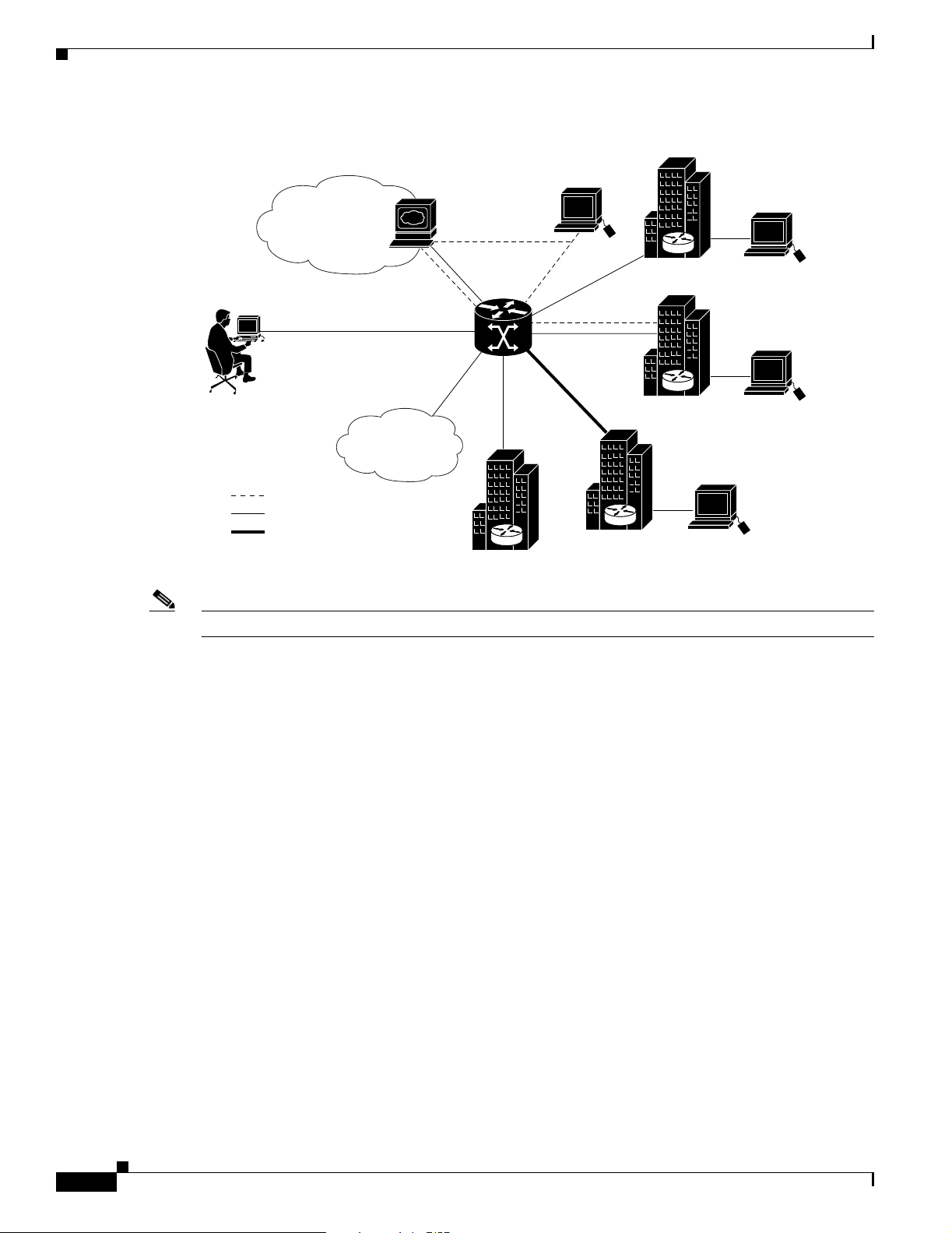
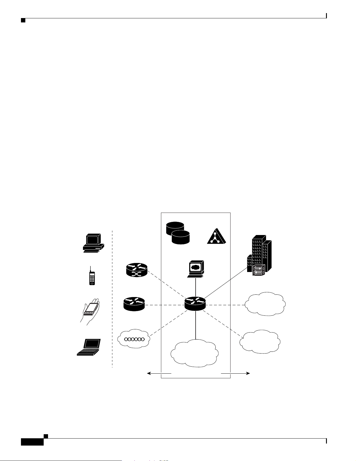
Figure 1-1 shows an example of an SSG topology. In the figure, a single user connects to the
Cisco 10000 series router using an access protocol such as PPP, RBE, or IP. SSG resides in the router
that serves as a broadband aggregator. The router acts as a central control point for Layer 2 and Layer 3
services, including services available through ATM virtual circuits (VCs), virtual private dial-up
networks (VPDNs), and normal routing methods. The user can concurrently connect to a number of
different services, which can be private or public services. Connections to the services are established
using IP.
Cisco 10000 Series Router Service Selection Gateway Configuration Guide
1-1
Page 16
Service Selection Gateway
Figure 1-1 SSG Topology Example
Default
Network
Web
Dashboard
Cisco 10000
router
RADIUS
AAA
Chapter 1 Service Selection Gateway Overview
Cisco
Secure
ISP/Service A
PPP/RBE/IP
Open
Garden
RADIUS
IP Data
Tunnel
ISP/Service C
Note The Cisco 10000 series router does not support tunneling of SSG users.
SSG
Extranet
The Cisco 10000 series router adds the Open Garden and default networks to all SSG VRFs, providing
reachability information to the Open Garden and default networks for all services both public and
private. However, access is restricted for the following conditions:
• If the Open Garden and default network addresses overlap within the service definition, the traffic
destined for either network is subject to the rules of the default network.
• If the Open Garden network is bound to a specific interface and a VRF is also applied to the
interface, the Open Garden network is accessible to users whose sessions are established using the
applied VRF.
RADIUS
AAA
ISP/Service B
RADIUS
AAA
87907
1-2
The SSG feature communicates with the authentication, authorization, and accounting (AAA)
management network that includes RADIUS and Dynamic Host Configuration Protocol (DHCP) servers.
SSG connects to the service provider network, which can connect to the Internet service provider (ISP)
network and corporate networks.
The Cisco 10000 series router supports the Cisco Subscriber Edge Services Manager (SESM), which
provides subscriber authentication, service selection, and service connection capabilities to subscribers
of Internet services. Subscribers interact with the SESM web application using a standard Internet
browser. The SESM functionality provides a flexible and convenient graphical user interface (GUI) for
subscribers and enables service providers to bill subscribers for connection time and services used,
rather than charging a flat rate.
Cisco 10000 Series Router Service Selection Gateway Configuration Guide
OL-4387-02
Page 17
Chapter 1 Service Selection Gateway Overview
Default Network
The default network is a location that SSG allows unauthenticated users to access. The default network
is a single IP address or subnet, typically the IP address of the SESM application although other types
of servers can also be defined as the default network. The default network supports the port-bundle host
key.
The default network enables special processing of traffic to and from the default network. Because traffic
to and from SESM requires special processing and the Cisco 10000 series router cannot distinguish
between SESM and non-SESM traffic, we recommend that you define the SESM server as the default
network and place other servers in the Open Garden network.
Note Traffic to and from a non-SESM server does not require special processing.
The SSG typically forwards packets to and from the default network through the router’s PXF forwarding
engine. However, SSG also forwards default network traffic through the route processor (RP) as follows:
Packets from a User and Destined for the Default Network
If the port-bundle host key is:
Service Selection Gateway
• Enabled—SSG forwards the packets through the RP.
• Disabled—SSG forwards the packets through the PXF forwarding engine.
Packets from the Default Network and Destined for an SSG User
• SSG forwards the packets through the RP if either of the following conditions are met:
• Otherwise, SSG forwards the packets through the PXF forwarding engine.
Access Protocols
On the subscriber side of the network, the Cisco 10000 series router supports SSG features for the
following protocols and encapsulations:
• PPPoE
• PPPoA
• RBE
• RFC 2684 IP
On the network side, the router supports receiving SSG traffic on the following interface types:
–
The port-bundle host key is enabled.
–
The port-bundle host key is disabled, TCP is the transport protocol, and the packets are
associated with an active TCP redirect mapping.
OL-4387-02
• ATM PVCs and subinterfaces
• Ethernet interfaces and subinterfaces
• POS interfaces
• Serial and channelized interfaces
Cisco 10000 Series Router Service Selection Gateway Configuration Guide
1-3
Page 18

Supported SSG Features
Supported SSG Features
The Cisco 10000 series router supports the following SSG features and functionality:
• SSG Logon and Logoff, page 3-1
• Authentication and Accounting, page 4-1
• Service Selection Methods, page 5-1
• Service Connection, page 6-1
• Service Profiles and Cached Service Profiles, page 7-1
• SSG Hierarchical Policing, page 8-1
• Interface Configuration, page 9-1
• SSG TCP Redirect, page 10-1
• VPI/VCI Static Binding to a Service Profile, page 11-1
• RADIUS Virtual Circuit Logging, page 11-2
• AAA Server Group Support for Proxy Services, page 11-2
Chapter 1 Service Selection Gateway Overview
• Packet Filtering, page 11-3
• SSG Unconfig, page 11-5
For more information about the SSG features, refer to the Service Selection Gateway, Release 12.2(15)B
feature module.
For information about SSG features supported in a specific Cisco IOS release, refer to the
Cisco 10000 Series Router Feature Map.
SSG Restrictions
The SSG feature has the following restrictions:
• When using SSG hierarchical policing on Cisco 10000 Series routers, a maximum of 8 policing rates
can be used per uplink interface and R attribute combination. Of these 8 rates, 1 is reserved for “no
policing”, leaving 7 different police rates available per uplink interface and R attribute combination
For example, if eight SSG services are bound to the same SSG next-hop and all eight services carry
an R attribute of “R0.0.0.0;0.0.0.0”, the ninth service will fail to acquire correct policing rates and
this error message may appear:
%GENERAL-3-EREVENT: C10KSSG: Vi2.8 svc_bitmap 0x2 Unable to set connection rate
• Network address translation (NAT) functionality is not supported. This means that the router does
not support concurrent access to multiple services for which the services, not the access provider,
must assign the user’s IP address. For example, this restriction applies to concurrent access to a
private service and SESM or the Open Garden network, or concurrent access to a tunnel service and
SESM or the Open Garden network.
1-4
• The Cisco 10000 series router adds reachability information to the Open Garden and default
networks for all services, both public and private. Because NAT is not supported, the addresses for
the Open Garden and default networks cannot overlap addresses defined within the service
definition.
• To restrict access to the Open Garden network by private services, you must specifically bind the
Open Garden to the uplink interfaces. Do not bind the Open Garden to the interface used by the
private service.
Cisco 10000 Series Router Service Selection Gateway Configuration Guide
OL-4387-02
Page 19

Chapter 1 Service Selection Gateway Overview
• The Cisco 10000 router’s SSG software and forwarding software handle multiple users attached to a
single Cisco IOS software interface in different ways, which could result in users receiving services
that they did not select. After the first user logs on, all subsequent user logon attempts are rejected.
Although the logon is rejected and thus the ability to select services, all users can access the services
to which the first user is subscribed. User traffic is not rejected, only the user’s authorization attempt.
The traffic from all users is logged in the statistics of the first user. The traffic to the user is treated as
transparent passthrough and is forwarded to the user, but it does not affect SSG accounting. If you enter
the ssg show host command, statistics are displayed for the first user only.
• For users attached to multipoint interfaces on the access side, the Cisco 10000 router authorizes the
first user and then rejects the authorization attempts of subsequent users. The router only rejects the
authorization attempts, not the user traffic. The router treats all subsequent users as the first user
logged on, allowing access to the services to which the first user is subscribed. However, subsequent
users cannot select services. The traffic from all users is logged in the statistics of the first user.
Traffic to the second and subsequent users is treated as transparent passthrough and is forwarded to
these users, but it does not affect the SSG accounting. The ssg show host command displays the first
user.
• Each private service is associated with its own VRF; global services are associated with the same
VRF. The default network and Open Garden network are typically added to all VRFs, except if the
network addresses overlap addresses in the private IP network or the Open Garden network is
explicitly bound to an uplink interface. The default network addresses must also be associated with
the global Cisco IOS VRF.
SSG Restrictions
• You can apply a service to a next-hop address or to an interface. The interface must be a
non-broadcast interface. For example, an interface with multipoint PVCs or Ethernet without
VLANs is not supported.
• You can apply services with overlapping addresses to the same next-hop address. Services that have
overlapping addresses cannot be bound to different next-hop addresses if the next-hop addresses
resolve to the same interface.
• All services that share an uplink interface must not have overlapping addresses. Normally, a service
defined to include a route of 0.0.0.0 with a subnet mask of 0.0.0.0 overlaps with any other possible
service. Therefore, the Cisco 10000 series router treats the route 0.0.0.0 with a subnet mask of
0.0.0.0 as a default route.
• You cannot configure the following interface types as an SSG uplink interface:
–
Any interface requiring tunneling (for example, L2TP or GRE tunneling)
–
Multilink PPP (MLPPP) interfaces
–
Tag interfaces
–
Load balanced interfaces
• For RBE and IP users, the addresses of services that share an uplink interface cannot overlap.
For information about the restrictions for a specific SSG feature, see the appropriate chapter in this
guide.
OL-4387-02
Cisco 10000 Series Router Service Selection Gateway Configuration Guide
1-5
Page 20
SSG Prerequisites
SSG Prerequisites
The SSG feature has the following prerequisites:
• The Cisco 10000 series router must be running Cisco IOS Release 12.2(16)BX or later.
• The performance routing engine (PRE), part number ESR-PRE2 must be installed in the router
chassis. The PRE performs all Layer 2 and Layer 3 packet manipulation related to routing and
forwarding operations. Use the show version command to verify that you have the correct PRE
version installed.
• If you want to perform Layer 3 service selection, you must install and configure the Cisco
Subscriber Edge Services Manager (SESM) as described in the Cisco Subscriber Edge Services
Manager and Subscriber Policy Engine Installation and Configuration Guide, Release 3.1(1).
For information about the prerequisites for a specific SSG feature, see the appropriate chapter in this
guide.
SSG Architecture Model
Chapter 1 Service Selection Gateway Overview
Figure 1-2 shows a Service Selection Gateway (SSG) model.
Figure 1-2 Service Selection Gateway Topology
PC
WAP
PDA
Notebook
AAA
DSL
GGSN
Wireless LAN
garden
Directory
Server
SESM
SSG
Open
Corporate
VPN
Internet
Gaming
1-6
Subscriber access media
Cisco 10000 Series Router Service Selection Gateway Configuration Guide
Services selection
Services
97064
OL-4387-02
Page 21

Chapter 1 Service Selection Gateway Overview
In Figure 1-2, subscribers access the SESM web portal application using any web browser on a variety
of devices (such as a desktop computer over DSL). The Cisco 10000 series router (the SSG node)
forwards unauthenticated SSG traffic from the subscriber to SESM, configured as the captive portal and
default network. The SSG feature set of the router allows the service provider to design a service
selection access network.
As the gateway to service selection, subscribers can use SESM to manager their accounts, subscribe to
new services, and select those services that they want to use. Service providers can use SESM to offer
and advertise value-added services and to associate these services with their brand identities.
SSG Architecture Model
OL-4387-02
Cisco 10000 Series Router Service Selection Gateway Configuration Guide
1-7
Page 22

SSG Architecture Model
Chapter 1 Service Selection Gateway Overview
1-8
Cisco 10000 Series Router Service Selection Gateway Configuration Guide
OL-4387-02
Page 23

Scalability and Performance
The infrastructure of the service provider must be capable of supporting the services the enterprise
customer or Internet service provider (ISP) wants to offer its subscribers. It must also be able to scale to
an expanding subscriber base. You can configure the Cisco 10000 series router for high scalability.
Limitations and Restrictions
The Cisco 10000 series router has the following limitations and restrictions for the SSG:
• Users can connect to a maximum of seven different services, plus the Open Garden and default
networks (a total of 9) at any one time.
• The Cisco 10000 series router supports mini-ACLs and turbo ACLs. Mini-ACLs are limited to eight
or less access control entries (ACEs); turbo ACLs have more than eight ACEs. ACLs can be standard
or extended ACLs. Non-SSG interfaces support both mini-ACLs and turbo ACLs. ACLs defined
through SSG configuration (RADIUS) are restricted to mini-ACLs only. You can apply the same
ACL to multiple hosts and connections.
CHAPTER
2
• The SSG QoS features are limited to hierarchical policing and are not based on the modular QoS
CLI (MQC).
• You cannot configure routing protocols in SSG VRFs. Therefore, RA-MPLS features are not
supported for SSG hosts.
• The Cisco 10000 series router does not support load balancing on SSG uplink interfaces or
redundant uplink interfaces to the same set of services.
• The Cisco 10000 series router does not support SSG services on tag interfaces.
• If you use the CLI to configure a VRF on an interface and you simultaneously configure the interface
as an SSG uplink interface, the Cisco 10000 series router accepts the configuration but the SSG
uplink configuration takes precedence and the router ignores the VRF configuration.
• You cannot configure overlapping IP addresses in the same VRF and you can associate a single
interface with a single VRF. The router makes routing decisions based on the longest match.
• The services applied on an IP network or networks must not have conflicting features. For example,
consider the following service definitions for the Best, Good, and Standard services. These service
definitions are in conflict because network A is not policed while network B is policed and also
restricted for some hosts.
Best—Access to network A and access to network B at rate 2
Good—Access to network A and access to network B at rate 1
Standard—Access to network A but no access to network B
OL-4387-02
Cisco 10000 Series Router Service Selection Gateway Configuration Guide
2-1
Page 24

Limitations and Restrictions
Chapter 2 Scalability and Performance
Now, consider the following revised service definitions in which two different services are defined.
These service definitions allow all users to connect to the Standard service and allow some users to
connect simultaneously to Good or Best services.
Best—Access to network B at rate 2
Good—Access to network B at rate 1
Standard—Access to network A
2-2
Cisco 10000 Series Router Service Selection Gateway Configuration Guide
OL-4387-02
Page 25

SSG Logon and Logoff
The Cisco 10000 series router supports the following SSG features for logon and logoff related
functions:
• Single Host Logon, page 3-1
• SSG Autologoff, page 3-2
• SSG Prepaid Idle Timeout, page 3-3
• SSG Session and Idle Timeout, page 3-6
This chapter describes each of SSG logon and logoff features.
Single Host Logon
The Single Host Logon feature enables users to enter authentication information only twice. To log on
to a service through the SESM web application, a subscriber enters authentication information once for
the PPP session and once for the service. The subscriber does not have to log on to the SESM. Instead,
the SESM uses the PPP authenticated information from the SSG.
CHAPTER
3
For non-PPP users, when a subscriber authenticates using the SESM application, the subscriber does not
have to log on again for the remainder of the non-PPP session. However, the subscriber still has to log
on to services. For more information, refer to Cisco Subscriber Edge Services Manager and Subscriber
Policy Engine Installation and Configuration Guide.
Prerequisites for Single Host Logon
T o use th e Single Host Logon feature, you must inst all and configure Cisco SESM Release 3.1(1) or later.
Cisco 10000 Series Router Service Selection Gateway Configuration Guide
OL-4387-02
3-1
Page 26

SSG Autologoff
SSG Autologoff
The SSG Autologoff feature enables SSG to verify connectivity with each host. SSG checks the status
of the connection with each host at configured intervals. If SSG finds that a host is not reachable, SSG
automatically initiates the logoff of that host. SSG has two methods of checking the connectivity of
hosts: ARP ping and ICMP ping.
ARP ping
When autologoff is configured to use ARP ping, SSG periodically checks the ARP cache tables. If a table
entry for a host is found, SSG forces ARP to refresh the entry and checks the entry again after a
configured interval. If a table entry is not found, SSG initiates autologoff for the host. However, if any
data traffic to or from the host occurred during the interval, SSG does not ping the host because the
reachability of the host during that interval was established by the data traffic. ARP ping works in
deployment scenarios in which all hosts are directly connected to the SSG through a broadcast interface
such as an Ethernet interface or through a bridged interface such as an RBE interface.
ICMP ping
Chapter 3 SSG Logon and Logoff
When SSG autologoff is configured to use ICMP ping, SSG pings the host to check connectivity until
an ICMP response is obtained or the allowable number of tries is used up. If all the tries are used up and
the ping was unsuccessful, then SSG initiates logoff for that host. SSG uses ICMP ping one time at each
configured interval. If data traffic to or from the host is found during the interval, SSG does not ping the
host because reachability was established by the data traffic. ICMP ping works in all types of deployment
scenarios and supports overlapping IP users.
Restrictions for SSG Autologoff
The SSG Autologoff feature has the following restrictions:
• Use only one method of SSG autologoff at a time: ARP ping or ICMP ping.
• Use ARP ping only in deployment scenarios in which all hosts are directly connected to the SSG
through a broadcast interface such as an Ethernet interface or through a bridged interface such as an
RBE interface. ICMP ping works in all types of deployment scenarios.
• ARP ping works only on hosts that have a MAC address.
• ARP ping does not support overlapping IP addresses.
• SSG autologoff that uses ARP ping does not work for hosts with static ARP entries.
• If you configure both the idle timers and ICMP-based autologoff, you must set the autologoff
interval to a value that is at least twice as long as the idle timeout interval. Otherwise, the
ICMP messages reset the idle timer and the user is only logged out if the user does not respond to
the ICMP ping.
Configuration of SSG Autologoff
To configure the SSG Autologoff feature, use the ssg auto-logoff command in global configuration
mode. For more information, refer to the SSG Autologoff, Release 12.2(4)B feature module.
Cisco 10000 Series Router Service Selection Gateway Configuration Guide
3-2
OL-4387-02
Page 27

Chapter 3 SSG Logon and Logoff
Configuration Example for SSG Autologoff
Example 3-1 shows how to enable autologoff with ARP ping.
Example 3-1 SSG Autologoff Using ARP Ping
ssg auto-logoff arp interval 60
Example 3-2 shows how to enable autologoff with ICMP ping.
Example 3-2 SSG Autologoff Using ICMP Ping
ssg auto-logoff icmp interval 60 packet 2 timeout 500
SSG Prepaid Idle Timeout
The SSG Prepaid Idle Timeout feature enhances the SSG and the SSG Prepaid feature by doing the
following:
SSG Prepaid Idle Timeout
• Enables SSG to return residual quotas (allotments of prepaid credit) to the billing server from
services that a user is logged into but not actively using. The quota that is returned to the billing
center can be applied to the quota for the services the user is actively using.
• Enables a user’s connection to services to be open even when the billing server returns a zero quota.
The connection’s status depends on the combination of the quota and the idle timeout value returned.
Depending on the connection service, SSG requests the quota for a connection from the billing
server at the following times:
–
After the user starts using a particular service
–
When the user runs out of quota
–
After the configured idle timeout value expires
• Enables SSG to reauthorize a user before the user completely consumes the allocated quota. You can
also configure SSG to not pass traffic during reauthorization, thus preventing revenue leaks in the
event the billing server returns a zero quota for the user.
• Enhances the handling of a returned zero quota from the billing server. If the billing server returns
a zero quota and a nonzero idle timeout, the user has run out of credit for a service. When a user
runs out of credit, the user is redirected to the billing server to replenish the quota. When the user is
redirected to the billing server, the user’s connection to the original service or services remains up,
but any traffic passing through the connection is dropped. This enables the user to replenish the
quota on the billing server without losing connections to services or having to perform additional
service logons.
• Enables SSG to notify the billing server when a connection fails. This enables the billing server to
free quota that was reserved for the failed connection and to apply the quota immediately to some
other active connection.
OL-4387-02
Without the SSG Prepaid Idle Timeout feature, traffic passed during reauthorization represents a revenue
leak if the billing server returns a zero quota for the user. A configurable threshold value is used to
prevent this. This value causes SSG to reauthorize a user’s connection before the user completely
consumes the allocated quota for a service.
Cisco 10000 Series Router Service Selection Gateway Configuration Guide
3-3
Page 28

SSG Prepaid Idle Timeout
Service Authorization
SSG sends a service authorization request to the billing server upon initial service authorization. Explicit
service authorization is required whenever a user attempts to connect to a prepaid service to ensure that
the user has sufficient credit to connect to that service. The billing server responds with the available
quota (allotment of prepaid credit) to SSG. If the returned available quota is greater than zero or not
present, SSG allows the user to connect to the service and begins metering based on the allotted quota.
For this authorization, an Access-Request is generated once the service is identified as a prepaid service.
The Access-Request is generated for service authorization regardless of the service type (for example,
virtual private dial-up network (VPDN), passthrough, proxy, or tunnel).
The billing server responds to the service authorization Access-Request with an Access-Accept that
defines the quota parameters for the connection. Authorization for a service is provided based on the
presence and content of the Quota (Attribute 26) and the Idle Timeout (Attribute 28) vendor-specific
attributes (VSAs) in the Access-Accept.
Service Reauthorization
SSG sends a service reauthorization request to the billing server at the following times:
Chapter 3 SSG Logon and Logoff
• When a prepaid user’s quota is consumed
• After the configured idle timeout expires
• When the user’s remaining quota reaches the configured threshold value
The SSG Prepaid Idle Timeout feature enables you to configure how traffic is handled during
reauthorization. By default, traffic continues during reauthorization. If the billing server returns a zero
quota in the reauthorization response, SSG disconnects the connection but the data that was in progress
during the reauthorization goes through and is not accounted. You can configure SSG to either drop or
forward traffic during reauthorization. You can also configure a threshold value, which configures SSG
to reauthorize a connection with the billing server before a prepaid user’s allocated quota is completely
consumed.
By configuring the ssg prepaid reauthorization drop-packet command, SSG drops the traffic on a
connection during reauthorization and the time used during the reauthorization is not accounted to that
connection. SSG deducts the reauthorization times from the total session duration time and sends the
Account Session Time (Attribute 46) in the Accounting Stop and Update packets.
If the billing server responds with a time-based connection to redirect the traffic, then SSG redirects
TCP traffic. The time of the TCP redirection is also not accounted to the user’s connection.
The reauthorization request for SSG Prepaid Idle Timeout is similar to the reauthorization request for
SSG Prepaid. However, the SSG Prepaid Idle Timeout reauthorization request contains an additional
attribute: Reauthorization Reason. If the Reauthorization Reason attribute is not present, the billing
server assumes that the reason for the reauthorization request is Primary Quota Consumed. The values
of the Reauthorization Reason attribute are the following:
• Quota Consumed (QR0)
3-4
• Idle Timer Expired (QR1)
For more information, refer to the SSG Prepaid Idle Timeout, Release 12.2(15)B feature module.
Cisco 10000 Series Router Service Selection Gateway Configuration Guide
OL-4387-02
Page 29

Chapter 3 SSG Logon and Logoff
Restrictions for SSG Prepaid Idle Timeout
The SSG Prepaid Idle Timeout feature has the following restrictions:
• The Cisco 10000 router supports only time-based SSG Prepaid for a service connection. Quotas are
measured in seconds. You cannot change the unit of measure.
• The Cisco 10000 router does not support returning a quota when the connection is idle.
• After a user runs out of quota and then replenishes the quota at the billing server, SSG receives the
updated quota and resumes the connection only after the next reauthorization.
Prerequisites for SSG Prepaid Idle Timeout
The SSG Prepaid Idle Timeout feature requires the following:
• You must enable SSG accounting before you can use the SSG Prepaid feature. SSG accounting is
enabled by default. If it has been disabled, reenable it by using the ssg accounting command in
global configuration mode.
• The SSG Prepaid feature requires the AAA server to support prepaid billing.
• You must configure the SSG to send Attribute 55 in accounting requests.
SSG Prepaid Idle Timeout
Configuration of SSG Prepaid Idle Timeout
To configure the SSG Prepaid Idle Timeout feature, configure the SSG Prepaid and SSG TCP Redirect
features. For more information, refer to the SSG Prepaid, Release 12.2(4)B feature module and the
SSG TCP Redirect for Services, Release 12.2(4)B feature module.
Configuration Example for SSG Prepaid Idle Timeout
Example 3-3 shows how to configure the SSG Prepaid feature to provide the prepaid billing server with
session ID and time-stamp information.
Example 3-3 SSG Prepaid Service
radius-server attribute 44 include-in-access-req
radius-server attribute 55 include-in-acct-req
Example 3-4 shows how to configure the SSG TCP Redirect feature. The commands configure a captive
portal group called "DefaultRedirectGroup," add two servers to "DefaultRedirectGroup," and redirect
prepaid users to the newly created captive portal.
Example 3-4 SSG TCP Redirect
ssg enable
ssg tcp-redirect
server-group DefaultRedirectGroup
server 10.0.0.1 8080
server 10.0.0.20 80
end
redirect prepaid-user to DefaultRedirectGroup
OL-4387-02
Cisco 10000 Series Router Service Selection Gateway Configuration Guide
3-5
Page 30

SSG Session and Idle Timeout
Example 3-5 shows how to configure the SSG TCP Redirect feature for a specific service. The
commands redirect all prepaid service traffic to the captive portal group called "InternetRedirectGroup"
and configure the captive portal group as the server group used for redirecting prepaid traffic.
Example 3-5 SSG Service-Specific TCP Redirect
ssg enable
ssg tcp-redirect
server-group InternetRedirectGroup
server 10.0.0.1 8080
server 10.0.0.20 80
end
The service profile for InternetRedirectGroup is shown here:
ServiceInfo="Z"
(Optional) You can configure SSG to reauthorize a prepaid user's connection before the user has
completely consumed the allotted quota for a service. To do this, enter the global-configuration
commands shown below to configure a time-based or a volume-based threshold value. Example 3-6
shows how to configure a threshold time value of 10 seconds. Example 3-7 shows how to configure
threshold volume value of 2000 bytes.
Chapter 3 SSG Logon and Logoff
Example 3-6 SSG Threshold Time
ssg prepaid threshold time 10
Example 3-7 SSG Threshold Volume
ssg prepaid threshold volume 2000
SSG Session and Idle Timeout
In a dial-up networking or bridged (non-PPP) network environment, a user can disconnect from the
network access server (NAS) and release the IP address without logging out from the SSG. When this
happens, the SSG continues to allow traffic to pass from that IP address, which can create a problem if
the another user obtains the same IP address. SSG provides two mechanisms to prevent this problem
from occurring:
• Session-Timeout RADIUS attribute—Specifies the maximum length of time for which a host or
connection object can remain continuously active.
• Idle-Timeout RADIUS attribute—Specifies the maximum length of time for which a session or
connection can remain idle before it is disconnected.
The Session-Timeout and Idle-Timeout attributes are used in either a user or service profile. In a user
profile, the attribute applies to the user session. In a service profile, the attribute applies individually to
each service connection.
3-6
Cisco 10000 Series Router Service Selection Gateway Configuration Guide
OL-4387-02
Page 31

Authentication and Accounting
The Cisco 10000 series router supports the following SSG features for authentication and accounting
related functions:
• SSG Full Username RADIUS Attribute, page 4-1
• RADIUS Accounting Records, page 4-2
This chapter describes the SSG features for authentication and accounting.
SSG Full Username RADIUS Attribute
The Full Username RADIUS attribute allows SSG to include the user’s full username and domain
(user@service) in the RADIUS authentication and accounting requests.
CHAPTER
4
Restrictions for SSG Full Username RADIUS Attribute
The size of the full username is limited to the smaller of the following values:
• 246 bytes (10 bytes less than the standard RADIUS protocol limitation)
• 10 bytes less than the maximum size of the RADIUS attribute supported by your proxy
Configuration Examples for SSG Full Username RADIUS Attribute
Example 4-1 RADIUS Freeware Format Example
Service-Info = “X”
Example 4-2 CiscoSecure ACS for UNIX Example
9,251 = “X”
OL-4387-02
Cisco 10000 Series Router Service Selection Gateway Configuration Guide
4-1
Page 32

RADIUS Accounting Records
RADIUS Accounting Records
SSG sends accounting records with the associated attributes to the RADIUS accounting server when the
following events occur:
• Account Login and Logout, page 4-2
• Service Connection and Termination, page 4-3
Account Login and Logout
SSG sends a RADIUS accounting-request record to the local RADIUS server when a user logs in to or
out of the SSG. The Acct-Status-Type attribute included in the accounting-request record indicates if the
accounting-request marks the start of the user service or the end of the service.
When a user logs in, SSG sends an accounting-start record to RADIUS. When a user logs out, SSG sends
an accounting-stop record.
Configuration Examples for Account Login and Logout
Chapter 4 Authentication and Accounting
Example 4-3 shows the information contained in a RADIUS accounting-start record.
Example 4-3 RADIUS Accounting-Start Record
Acct-Status-Type = Start
NAS-IP-Address = ip_address
User-Name = "username"
Acct-Session-Id = "session_id"
Framed-IP-Address = user_ip
Proxy-State = "n"
Example 4-4 shows the information contained in a RADIUS accounting-stop record.
Example 4-4 RADIUS Accounting-Stop Record
Acct-Status-Type = Stop
NAS-IP-Address = ip_address
User-Name = "username"
Acct-Session-Time = time
Acct-Terminate-Cause = cause
Acct-Session-Id = "session_id"
Framed-IP-Address = user_ip
Proxy-State = "n"
The Acct-Session-Time attribute indicates the length of session, expressed in seconds. The
Acct-Terminate-Cause attribute indicates the reason for account termination, which can be due to the
following events:
4-2
• User-Request
• Session-Timeout
• Idle-Timeout
• Lost-Carrier
Cisco 10000 Series Router Service Selection Gateway Configuration Guide
OL-4387-02
Page 33

Chapter 4 Authentication and Accounting
Service Connection and Termination
SSG also sends a RADIUS accounting-request record to the local RADIUS server when a user accesses
or terminates a service. The Acct-Status-Type attribute included in the accounting-request record
indicates whether the accounting-request marks the start of the user service or the end of the service.
When a user accesses a service, SSG sends an accounting-start record to RADIUS. When a user
terminates a service, SSG sends an accounting-stop record.
Configuration Examples for Service Connection and Termination
Example 4-5 shows the information contained in an accounting-start record for service access.
Example 4-5 RADIUS Accounting-Start Record for Service Access
User-Name = "username"
Acct-Status-Type = Start
Acct-Authentic = RADIUS
Service-Type = Framed
Acct-Session-Id = "00000010"
Framed-Protocol = PPP
Service-Info = "Nisp-name.com"
Service-Info = "Uusername"
Service-Info = "TP"
Acct-Delay-Time = 0
RADIUS Accounting Records
The following list describes some of the attributes included in the record. For more information, refer to
the Service Section Gateway, Release 12.2(15)B feature module.
• Acct-Status-Type—Indicates that the accounting-request marks the start of the user service.
• Service-Type—Indicates the type of service requested or the type of service to be provided. PPP and
SLIP connections use the service type.
• Service-Info—Indicates the following:
–
Nname—Indicates the name of the service profile.
–
Uname—Indicates the username used to authenticate the user with the remote RADIUS server.
This attribute is used for proxy services.
–
Ttype—Indicates whether the connection is proxy (X), tunnel (T), or passthrough (P).
OL-4387-02
Cisco 10000 Series Router Service Selection Gateway Configuration Guide
4-3
Page 34

RADIUS Accounting Records
Example 4-6 shows the information contained in an accounting-stop record for service termination.
Example 4-6 RADIUS Accounting-Stop Record for Service Termination
NAS-IP-Address = 192.168.2.48
NAS-Port = 0
NAS-Port-Type = Virtual
User-Name = "zeus"
Acct-Status-Type = Stop
Service-Type = Framed-User
Acct-Session-Id = "00000002"
Acct-Terminate-Cause = User-Request
Acct-Session-Time = 84
Acct-Input-Octets = 0
Acct-Output-Octets = 649
Acct-Input-Packets = 0
Acct-Output-Packets = 17
Framed-Protocol = PPP
Framed-IP-Address = 201.168.101.10
Control-Info = "I0;0"
Control-Info = "O0;649"
Service-Info = "Ninternet"
Service-Info = "Uzeus"
Service-Info = "TP"
Acct-Delay-Time = 0
Chapter 4 Authentication and Accounting
The following describes some of the attributes included in the record. For more information, refer to the
Service Section Gateway, Release 12.2(15)B feature module.
• Acct-Status-Type—Indicates that the accounting-request marks the end of the user service.
• Service-Type—Indicates the type of service.
• Acct-Session-Time—Indicates how long the user has been receiving service and is expressed in
seconds.
• Acct-Terminate-Cause—Indicates the reason for service termination, which can be due to the
following events:
–
User-Request
–
Lost-Carrier
–
Lost-Service
–
Session-Timeout
–
Idle-Timeout
4-4
Cisco 10000 Series Router Service Selection Gateway Configuration Guide
OL-4387-02
Page 35

Service Selection Methods
The Cisco 10000 series router supports the following service selection methods:
• PPP Terminated Aggregation, page 5-1
• PTA-Multidomain, page 5-1
• Web Service Selection, page 5-2
This chapter describes the service selection methods.
PPP Terminated Aggregation
PPP terminated aggregation (PTA) is a PPP selection method in which service selection is based on a
structured domain name (for example, username@service.com). PTA terminates the PPP session into a
single routing domain. Users can only access one service and users do not have access to the default
network or SESM.
CHAPTER
5
The PTA-MD exclusion list allows you to create a set of domains that you want to exclude from
SSG processing. When a PPP user attempts to establish a PPP session using a domain that is included in
the exclusion list, the traffic is treated as non-SSG traffic and is processed by Cisco IOS software. The
system does not apply SSG features and processing to the traffic.
PTA-Multidomain
PTA-Multidomain (PTA-MD) is a PPP selection method in which service selection is based on a
structured domain name (for example, username@service.com). PTA-MD terminates the PPP sessions
into multiple IP routing domains. SSG features and processing are applied to the user traffic and users
can access one or more services at a time. PTA-MD service selection supports a wholesale VPN model
where each domain is isolated from the other and has the capability to support overlapping IP addresses.
The Cisco 10000 series router implements PTA-MD service selection in the following way:
• The access provider terminates the user PPP sessions and logically associates each session with a
particular service.
• Network side interfaces are associated with a service. SSG binds the user session and its service to
the appropriate network side interface.
• SSG binds the network side interface associated with a service to a virtual routing and forwarding (VRF)
instance. All users who subscribe to that service are also bound to that same VRF. Packets to and from
the user and to and from the network side interface are routed within the same VRF.
OL-4387-02
Cisco 10000 Series Router Service Selection Gateway Configuration Guide
5-1
Page 36

Web Service Selection
Restrictions for PTA-MD
A user cannot connect to multiple services that are simultaneously in different VRFs.
Web Service Selection
Web service selection enables users to concurrently access multiple on-demand services from a list of
personalized services. The Cisco 10000 series router supports the Cisco Subscriber Edge Services
Manager (SESM) application for web service selection.
The SESM application provides subscriber authentication, service selection, and service connection
capabilities to subscribers of Internet services. Subscribers interact with the SESM web application
using a standard Internet browser. They do not need to download any software or plug-ins to use the
SESM web pages. After a subscriber successfully authenticates, the SESM web application presents a
list of services that the subscriber is currently authorized to use. The subscriber can gain access to one
or more of those services by selecting them from a web page. Alternatively, an automatic connection
feature might provide automatic connection to services.
SESM works in conjunction with other network components to provide extremely robust, highly scalable
connection management to Internet services. Internet service providers (ISPs) and network access
providers (NAPs) deploy SESM to provide their subscribers with a web interface for accessing multiple
Internet services. The ISPs and NAPs can customize and brand the content of the web pages and thereby
control the user experience for different categories of subscribers.
Chapter 5 Service Selection Methods
SESM Release 3.1(1) or later is a solution composed of a number of applications built on a core set of
software components. ISPs and NAPs can use these core components to further develop and customize
SESM web applications, if required. The Cisco Subscriber Edge Services Manager Web Developer
Guide, Release 3.1(7) describes how to develop SESM applications.
SESM web applications (Release 3.1(1) or later) deployed in Directory Enabled Service
Selection/Subscription (DESS) mode incorporate the use of the Cisco Subscriber Policy Engine (SPE)
Release 1.0. The SPE allows subscribers to perform account maintenance and self-care activities, such
as subscribing to new services, creating subaccounts (for other members of the family, for example), and
changing basic account information, such as address, phone number, and e-mail.
For subscribers of Internet services, the SESM web application offers flexibility and convenience,
including the ability to access multiple services simultaneously.
For Internet service providers, the SESM web application provides a way to control the subscriber
experience and promote customer loyalty. Service providers can change the look and feel of their SESM
web application, brand the application, and control the content of the pages displayed to their
subscribers.
For more information, refer to the SESM documentation.
5-2
Cisco 10000 Series Router Service Selection Gateway Configuration Guide
OL-4387-02
Page 37

Chapter 5 Service Selection Methods
SESM and SSG Performance
Packets sent between the SSG and the SESM might require processing by the Cisco 10000 router Route
Processor (RP), instead of the parallel express forwarding (PXF) engine.
The following conditions require RP processing of packets:
• When the SESM interface is connected to the network management (NME) port of the performance
routing engine (PRE, Part Number ESR-PRE2), all traffic between the SSG and the SESM is passed
to the RP for processing.
• When the SESM is connected to one of the line card interfaces and the Port-Bundle Host Key feature
is configured on the SSG, all packets sent to and from the SESM are passed to the RP for processing.
• When the SESM is connected to one of the line card interfaces and TCP redirect is enabled, all
TCP packets from the SESM to the SSG are passed to the RP for processing.
Note The RP does not have as much forwarding capacity as the PXF.
Web Service Selection
OL-4387-02
Cisco 10000 Series Router Service Selection Gateway Configuration Guide
5-3
Page 38

Web Service Selection
Chapter 5 Service Selection Methods
5-4
Cisco 10000 Series Router Service Selection Gateway Configuration Guide
OL-4387-02
Page 39

Service Connection
The Cisco 10000 series router supports the following SSG features for service connection:
• SSG AutoDomain, page 6-1
• SSG Prepaid, page 6-4
• SSG Open Garden, page 6-5
• SSG Port-Bundle Host Key, page 6-6
• Exclude Networks, page 6-8
• Mutually Exclusive Service Selection, page 6-8
This chapter describes the SSG features for service connection.
SSG AutoDomain
CHAPTER
6
The SSG AutoDomain feature allows users to automatically connect to a service based on the domain
part of the structured username specified in an Access-Request. When SSG AutoDomain is configured,
user authentication is performed at the service (for example, at the AAA server within a corporate
network), instead of at the network access server (NAS).
The domain portion of the structured username is the portion after the @ in the username. For example,
the domain in the username “abc@cisco.com” is “cisco.com”. Users can bypass the Service Selection
Dashboard (SSD) and access a service, such as a corporate intranet. SSG AutoDomain on the
Cisco 10000 router supports login operations from the Subscriber Edge Services Manager (SESM)
application.
AutoDomain uses a heuristic to determine the service into which the user is logged. The host object is
not activated until successfully authenticated with the service. If the autoservice connection fails for any
reason, the user login is rejected.
The AutoDomain service first checks for a structured username. If AutoDomain is enabled and the
received Access-Request specifies a structured username, the username is used for AutoDomain
selection. If the Access-Request does not specify a username or the specified username is a member of
the domain name exclusion list, then no AutoDomain is selected and normal SSG user login proceeds.
You can define the domain name exclusion list by using the exclude command in SSG-auto-domain
configuration mode.
When you enable AutoDomain, an AutoDomain profile is downloaded from the local AAA server. This
profile specifies an outbound service and the password is the globally configured service password.
OL-4387-02
Cisco 10000 Series Router Service Selection Gateway Configuration Guide
6-1
Page 40

SSG AutoDomain
You can configure SSG AutoDomain in basic or extended mode. In basic mode, the AutoDomain profile
downloaded from the AAA server is a service profile. This service profile is a proxy or VPDN service.
If the AutoDomain service profile is a proxy service, SSG authenticates the user to the appropriate
domain AAA server with the authentication information found in the Access-Request received from the
RADIUS client. If the downloaded AutoDomain service profile is a tunnel service, a PPP session is
regenerated into an L2TP tunnel for the selected service. If the returned SSG-specific attributes do not
indicate the type of service required, SSG treats this service as a VPDN service.
In extended AutoDomain mode, the downloaded profile is a “virtual user” profile that contains one
autoservice to an authenticated service such as a proxy or VPDN. The host object is not activated until
the user is authenticated at the proxy or VPDN service. If the “virtual user” profile does not have exactly
one autoservice or the autoservice is not authenticated, the AutoDomain login is rejected.
If you configure basic SSG AutoDomain with a nonauthenticated service type (for example,
passthrough), SSG rejects the login request because AutoDomain bypasses user authentication at the
local AAA server and requires that authentication be performed elsewhere.
For more information, refer to the SSG AutoDomain, Release 12.2(4)B feature module.
Restrictions for SSG AutoDomain
Chapter 6 Service Connection
SSG AutoDomain has the following restrictions:
• Restricted DHCP support—DHCP requests for IP address assignment must be done before RADIUS
negotiation.
• Passthrough services—Because local authentication at the network access server (NAS) is bypassed,
AutoDomain is available only for services that perform authentication (for example, proxy or
VPDN services).
• “Virtual-user” profiles can contain only one AutoLogon service.
• If an Access-Request does not contain an IP address, you must configure a local per-domain or
global IP address pool.
Configuration of SSG AutoDomain
To enable SSG AutoDomain and enter SSG autodomain configuration mode, use the ssg auto-domain
command in global configuration mode. To verify the configuration, use the show running-config
command in privileged EXEC mode.
For more information, refer to the SSG AutoDomain, Release 12.2(4)B feature module.
Configuration Example for SSG AutoDomain
Example 6-1 shows a sample configuration for SSG AutoDomain. In the example, AutoDomain is
configured for extended-mode, and the called-station-id(APN) is used to select the AutoDomain service.
If the service assigns an IP address, then SSG performs Network Address Translation (NAT) on the
connection.
6-2
The example creates an AutoDomain exclude list by downloading the profile
“ssg-auto-domain-exclude-profile” from the AAA server (the download password is “cisco”). The
configuration also includes two exclude entries: cisco (exclude APN), and motorola (exclude domain name).
Cisco 10000 Series Router Service Selection Gateway Configuration Guide
OL-4387-02
Page 41

Chapter 6 Service Connection
Example 6-1 SSG AutoDomain
ssg auto-domain
mode extended
select called-station-id
nat user-address
download exclude-profile ssg-auto-domain-exclude-profile cisco
exclude apn cisco
exclude domain motorola
Example 6-2 shows the format for defining a new vendor-specific attribute, SSG Control-Info VSA(253),
which is required for the AutoDomain exclude profile on the AAA server.
Example 6-2 AutoDomain Exclude Profile SSG VSA Format
code: 253, 'X'
len: > 4
+-+-+-+-+-+-+-+-+-+-+...-+
|a|b| c |d|e|f|p| g |
+-+-+-+-+-+-+-+-+-+-+...-+
a = 26 (Radius attribute for vendor specific)
b = len (length of the Radius vendor-specific)
c = 9 (Cisco vendor ID)
d = 253 (sub-attribute ID for Service-Info)
e = len (length of the vendor-specific filter)
p = 'X' (Excluded Name List Entry Flag)
g = "A<apn-name>" or (Add this name to APN exclude list)
"D<domain-name>" (Add this name to Domain name exclude list)
SSG AutoDomain
Example 6-3 shows a sample configuration for an AutoDomain exclude file.
Example 6-3 AutoDomain Exclude File Format
user = ssg-auto-domain-exclude-profile{
radius=SSGDictionary {
check_items= {
2=cisco
}
reply_attributes= {
9,253="XDcisco"
9,253="XDmotorola"
9,253="XAalcatel"
9,253="XAnokia"
}
}
}
OL-4387-02
Cisco 10000 Series Router Service Selection Gateway Configuration Guide
6-3
Page 42

SSG Prepaid
SSG Prepaid
The SSG Prepaid feature allows a user to connect to a service if the user has prepaid for the service. SSG
checks a subscriber’s available credit to determine whether to connect the subscriber to the service and
how long the connection can last. The billing server administers the subscriber’s credit as a series of
quotas. These quotas are allotments of available credit and represent the duration of use, expressed in
seconds.
Note The Cisco 10000 series router does not support quotas that are based on allowable data volume. The
router supports only time-based quotas.
To obtain the first quota for a connection, SSG submits an authorization request to the AAA server. The
AAA server contacts the prepaid billing server, which forwards the quota values to SSG. SSG then
monitors the connection to track the quota usage. When the quota runs out, SSG performs
reauthorization. During reauthorization, the billing server can provide SSG with an additional quota if
there is available credit. If no further quota is provided, SSG logs off the user.
For more information, refer to the SSG Prepaid, Release 12.2(4)B feature module.
Chapter 6 Service Connection
Restrictions for SSG Prepaid
The SSG Prepaid feature has the following restrictions:
• Quotas are measured in seconds. You cannot change the unit of measure.
• The Cisco 10000 router supports only time-based SSG Prepaid for a service connection.
Configuration of SSG Prepaid
To configure SSG to provide the prepaid billing server with session ID and time-stamp information, use
the radius-server attribute command in global configuration mode. The command syntax is:
radius-server attribute 44 include-in-access-req (Accounting Session ID)
radius-server attribute 55 include-in-acct-req (Event-Timestamp)
To configure a global prepaid server group for authorization, use the aaa group server radius command
in global configuration mode and then use the ssg aaa group prepaid command in global configuration
mode to attach the global prepaid server group to the SSG. The command syntax is:
aaa group server radius
ssg aaa group prepaid
For more information, refer to the SSG Prepaid, Release 12.2(4)B feature module.
group-name
group-name
6-4
Cisco 10000 Series Router Service Selection Gateway Configuration Guide
OL-4387-02
Page 43

Chapter 6 Service Connection
Configuration Example for SSG Prepaid
Example 6-4 configures a global prepaid server group named ssg_prepaid and attaches the server group
to the SSG.
Example 6-4 Attaching a Global Prepaid Server Group to the SSG
Router(config)# aaa group server radius ssg_prepaid
Router(config-sg)# server 1.2.3.4 auth-port 1645 acct-port 1646
Router(config-sg)# exit
Router(config)# ssg aaa group prepaid ssg_prepaid
SSG Open Garden
An Open Garden is a collection of networks or web sites that subscribers can access as long as they have
physical access to the network. Subscribers do not have to provide authentication information before
accessing the networks in an Open Garden. The network is not restricted by service selection,
subscription, or policing.
SSG Open Garden
Figure 6-1 shows a network topology that includes Open Garden networks.
Figure 6-1 Open Garden Network Topology
Open garden 1
SSG
Open garden 2
Next-hop gateway
62669
If SSG receives a packet from a subscriber that is destined for the Open Garden, SSG forwards the packet
even if the subscriber is not authenticated. SSG forwards all packets destined for the Open Garden
whether or not the subscriber is authenticated.
If SSG receives a packet from a subscriber that is not destined for the Open Garden and the subscriber
is not authenticated, SSG drops the packet. If the subscriber is authenticated, SSG forwards the packet.
While most SSG services must be bound to an interface or next-hop address, it is not necessary to bind
Open Garden services that are directly connected to the SSG router. Service binding is mandatory,
however, for Open Garden services that are routed through a next-hop address.
For more information, refer to the SSG Open Garden, Release 12.2(4)B feature module.
OL-4387-02
Cisco 10000 Series Router Service Selection Gateway Configuration Guide
6-5
Page 44

SSG Port-Bundle Host Key
Restrictions for SSG Open Garden
The SSG Open Garden feature has the following restrictions:
• RADIUS accounting records are not created for Open Garden services.
• The Cisco 10000 router supports the creation of Open Garden services by using local profiles only;
you cannot use RADIUS profiles.
• The Cisco 10000 router does not support overlapping Open Garden service networks.
Configuration of SSG Open Garden
To designate a service as an Open Garden service, use the ssg open-garden command in global
configuration mode. For more information on configuring an Open Garden, refer to the
SSG Open Garden, Release 12.2(4)B feature module.
Configuration Example for SSG Open Garden
Chapter 6 Service Connection
The following example defines two services named og1 and og2 and adds them to the Open Garden.
!
ssg open-garden og1
ssg open-garden og2
!
local-profile og1
attribute 26 9 251 “Oopengarden1.com”
attribute 26 9 251 “D10.13.1.5”
attribute 26 9 251 “R10.1.1.0;255.255.255.0
local-profile og2
attribute 26 9 251 “Oopengarden2.com”
attribute 26 9 251 “D10.14.1.5”
attribute 26 9 251 “R10.2.1.0;255.255.255.0”
attribute 26 9 251 “R10.3.1.0;255.255.255.0”
!
ssg bind service og2 10.5.5.1
SSG Port-Bundle Host Key
The SSG Port-Bundle Host Key feature enhances communication and functionality between SSG and
SESM by introducing a mechanism that uses the host source IP address and source port to identify and
monitor subscribers.
With the SSG Port-Bundle Host Key feature, SSG performs port-address translation (PAT) and
network-address translation (NAT) on the HTTP traffic between the subscriber and the SESM server.
When a subscriber sends an HTTP packet to the SESM server, SSG creates a port map that changes the
source IP address to a configured SSG source IP address and changes the source TCP port to a port
allocated by SSG. SSG assigns a bundle of ports to each subscriber because one subscriber can have
several simultaneous TCP sessions when accessing a web page. The assigned host key, or combination
of port-bundle and SSG source IP address, uniquely identifies each subscriber. The host key is carried
in RADIUS packets sent between the SESM server and SSG in the Subscriber IP vendor-specific
attribute (VSA). When the SESM server sends a reply to the subscriber, SSG translates the destination
IP address and destination TCP port according to the port map.
6-6
Cisco 10000 Series Router Service Selection Gateway Configuration Guide
OL-4387-02
Page 45

Chapter 6 Service Connection
For each TCP session between a subscriber and the SESM server, SSG uses one port from the port bundle
as the port map. Port mappings are flagged as eligible for reuse on the basis of inactivity timers, but are
not explicitly removed once assigned. The number of port bundles is limited, but you can assign multiple
SSG source IP addresses to accommodate more subscribers.
SSG assigns the base port of the port bundle to a port map only if SSG has no state information for the
subscriber or if the state of the subscriber has changed. When the SESM server sees the base port of a
port bundle in the host key, SESM queries SSG for new subscriber state information.
For more information, refer to the SSG Port-Bundle Host Key, Release 12.2(4)B feature module.
Restrictions for SSG Port-Bundle Host Key
The SSG Port-Bundle Host Key feature has the following restrictions:
• You must separately enable the SSG Port-Bundle Host Key feature at the SESM and at all connected
SSG nodes.
• To enable the SSG Port-Bundle Host Key feature, you must reload SSG and restart the SESM.
• When you change the port-bundle length, the change does not take effect until after the router
reloads.
SSG Port-Bundle Host Key
• All SSG source IP addresses configured using the ssg port-map source ip command must be
routable in the management network where the SESM resides.
• For each SESM server, all connected SSG nodes must have the same port-bundle length.
• RFC 1483, local bridged, or routed clients cannot have overlapping IP addresses, even across
different interfaces.
• Enabling the SSG Port-Bundle Host Key feature requires additional PXF processing.
• The Cisco 10000 router’s SSG software and forwarding software handle multiple users attached to
a single Cisco IOS interface in different ways, which could result in users receiving services that
they did not select. After the first user logs on, all subsequent user logon attempts are rejected.
Although the logon is rejected and thus the ability to select services, all users can access the services
to which the first user is subscribed. User traffic is not rejected, only the user’s authorization
attempt. The traffic from all users is logged in the statistics of the first user. Traffic to the second
and subsequent user(s) is treated as transparent passthrough and is forwarded to these users, but it
does not affect the SSG accounting. The ssg show host command displays the first user.
• For users attached to multipoint interfaces on the access side, the Cisco 10000 router authorizes the
first user and then rejects the authorization attempts of subsequent users. The router only rejects the
authorization attempts, not the user traffic. The router treats all subsequent users as the first user
logged on, allowing access to the services to which the first user is subscribed. However, subsequent
users cannot select services. The traffic from all users is logged in the statistics of the first user.
Traffic to the second and subsequent user(s) is treated as transparent passthrough and is forwarded
to these users, but it does not affect the SSG accounting. The ssg show host command displays the
first user.
OL-4387-02
Cisco 10000 Series Router Service Selection Gateway Configuration Guide
6-7
Page 46

Exclude Networks
Prerequisites for SSG Port-Bundle Host Key
The SSG Port-Bundle Host Key feature has the following requirements:
• The Cisco 10000 router supports the SSG Port-Bundle Host Key feature for Cisco SESM
Release 3.1(1) or later.
• A default network must be configured and routable from SSG.
Configuration of SSG Port-Bundle Host Key
The port-bundle host key is disabled by default. To enable the host key and enter the SSG port map
configuration mode, use the ssg port-map enable command in global configuration mode.
After you enable the host key, perform the following configuration tasks:
• Specify the subscriber traffic to be port-mapped by using the following command in SSG port
configuration mode:
Router(config-ssg-port)# destination range
start-port
to
Chapter 6 Service Connection
end-port
[ip
A.B.C.D
]
• Specify the SSG source IP addresses by using the following command in SSG port configuration
mode:
Router(config-ssg-port)# source ip {
• Specify the length of the port bundle by using the following command in SSG port configuration
interface
mode:
Router(config-ssg-port)# length port-bundle
For more information on configuring the SSG Port-Bundle Host Key feature, refer to the
SSG Port-Bundle Host Key, Release 12.2(4)B feature module.
Exclude Networks
The Exclude Networks feature allows you to specify networks to which users cannot automatically log
on. To add names to the autodomain download exclusion list, use the download exclude-profile
command in SSG autodomain configuration mode.
For more information, refer to the SSG AutoDomain, Release 12.2(4)B feature module.
Mutually Exclusive Service Selection
The Mutually Exclusive Service Selection feature restricts a subscriber to accessing only one service at
a time in a specified group of services.
|
ip-address
length
}
6-8
A service group is a collection of services defined in a service group profile. A subscription to a service
group implies subscription to all of the services in the group. It also implies the ability to select all of
the services in the group. However, when a group is defined as mutually exclusive, SESM limits service
selection to one service at a time within the group.
Cisco 10000 Series Router Service Selection Gateway Configuration Guide
OL-4387-02
Page 47

Chapter 6 Service Connection
A SESM configuration option controls the SESM action when a subscriber is already logged into one
service and then selects another service in the group:
• SESM can automatically request SSG to disconnect the first service and connect the new service.
• SESM can prompt the subscriber to log off the first service. After the subscriber logs off, SESM
requests the connection to the other service.
Note SESM waits for the first service to be disconnected before requesting connection to the new service. If
the connection to the new service fails, the subscriber is not connected to either service.
Configuration of Mutually Exclusive Service Selection
You define a mutually exclusive service group in a service group profile by using the Account-Info
attribute. The value TE indicates that the service group is mutually exclusive.
For more information, refer to the ”Configuring Service Group Profiles” section in Appendix D,
Configuring RADIUS in the Cisco Subscriber Edge Services Manager and Subscriber Policy Engine
Installation and Configuration Guide, Release 3.1(3).
Mutually Exclusive Service Selection
Configuration Example for Mutually Exclusive Service Selection
Example 6-5 shows a mutually exclusive service group configuration that uses a Merit RADIUS format.
Example 6-5 Configuring a Mutually Exclusive Service Selection Group
MutexGrp1 Password = "groupcisco", Service-Type = Outbound
Account-Info = "IBandwidth-QoS",
Account-Info = "Nbw-gold",
Account-Info = "Nbw-silver",
Account-Info = "Nbw-bronze",
Account-Info = "TE"
OL-4387-02
Cisco 10000 Series Router Service Selection Gateway Configuration Guide
6-9
Page 48

Mutually Exclusive Service Selection
Chapter 6 Service Connection
6-10
Cisco 10000 Series Router Service Selection Gateway Configuration Guide
OL-4387-02
Page 49

Service Profiles and Cached Service Profiles
The RADIUS server or the SESM downloads service profiles to the Cisco 10000 series router (SSG
node) as needed. Typically, the SSG removes the service profile from memory after the user logs off.
Therefore, each time the user attempts to access services, RADIUS or the SESM downloads the service
profile, creating unnecessary traffic. The Cached Service Profiles feature is designed to eliminate this
inefficient overhead.
This chapter describes the service profiles and cached service profiles supported by the Cisco 10000
series router:
• Service Profiles, page 7-1
• Cached Service Profiles, page 7-4
Service Profiles
CHAPTER
7
Service profiles define the services that subscribers can select. Each service that is accessible has a
profile that defines the attributes of the service. Service profiles are configured on the RADIUS server
or directly on the Cisco 10000 series router. The RADIUS server or SESM downloads the service
profiles to the router as needed.
Service profiles include the following information: password, service type (outbound), type of service
(passthrough or proxy), service access mode (sequential or concurrent), DNS server IP address,
networks that exist in the service domain, access control lists, and timeouts. The following sections
describe the attributes included in RADIUS service profiles. For more information, refer to the
”Service Selection Gateway” chapter in the Cisco 6400 Feature Guide, Release 12.2(2)B.
Downstream Access Control List
Specifies either an IOS standard access control list or an extended access control list to be applied to
downstream traffic going to the user.
Cisco-AVpair = “ip:outacl [#
extended-access-control-list
number
}”
]={
standard-access-control-list
|
OL-4387-02
Cisco 10000 Series Router Service Selection Gateway Configuration Guide
7-1
Page 50

Service Profiles
Upstream Access Control List
Specifies either an IOS standard access control list or an extended access control list to be applied to
upstream traffic coming from the user.
Cisco-AVpair = “ip:inacl[#
extended-access-control-lis
Domain Name
(Optional) Specifies domain names that get DNS resolution from the DNS server(s) specified by the
DNS server address.
Service-Info = “
Oname
Full Username
Indicates that RADIUS authentication and accounting requests use the full username (user@service).
Service-Info = “X”
numbe
r]={
t}”
1[;
name2]...[;name
Chapter 7 Service Profiles and Cached Service Profiles
standard-access-control-list
X]”
|
MTU Size
Specifies the PPP MTU size of the SSG as a LAC. By default, the PPP MTU size is 1500 bytes.
Service-Info = "
Note In Directory Enable d Service Sel ection Subscri ption (DE SS) mode, SESM does not supp ort the use of
Bsiz
this attribute.
RADIUS Server
Specifies the remote RADIUS servers that SSG uses to authenticate, authorize, and perform accounting
for a service logon for a proxy service type. This attribute is only used in proxy service profiles and is
required.
You can configure each remote RADIUS server with timeout and retransmission parameters. SSG will
perform failover among the servers.
Service-Info =
SRadius-server-address;auth-port;acct-port;secret-ke
“
Service Authentication Type
Specifies whether the SSG uses the CHAP or PAP protocol to authenticate users for proxy services.
Service-Info = "
Aauthen-typ
e"
e"
y[;
retrans;timeout;deadtim
e]”
7-2
Cisco 10000 Series Router Service Selection Gateway Configuration Guide
OL-4387-02
Page 51

Chapter 7 Service Profiles and Cached Service Profiles
Service-Defined Cookie
Enables you to include user-defined information in RADIUS authentication and accounting requests.
Service-Info = “
Note • SSG does not parse or interpret the value of the Service-Defined Cookie. You must configure the
Vstrin
proxy RADIUS server to interpret this attribute.
• SSG supports only one Service-Defined Cookie per RADIUS service profile.
Service Description
(Optional) Describes the service.
Service-Info = “
Idescriptio
Service Mode
Service Profiles
g”
n”
(Optional) Defines whether the user is able to log on to this service while simultaneously connected to
other services (concurrent mode) or whether the user cannot access any other services while using this
service (sequential mode). The default is concurrent mode.
Service-Info = “
Mmode
Service Next-Hop Gateway
(Optional) Specifies the next-hop key for this service. Each SSG uses its own next-hop gateway table to
associate this key with an actual IP address.
Service-Info = “
Gkey
Service Route
Specifies networks available to the user for this service.
Service-Info = “
Rip_address;mask
Service URL
(Optional) Specifies the URL that is displayed in the SESM HTTP address field when the service opens.
Service-Info = “
Hurl
”
”
”
”
OL-4387-02
or
Service-Info = “
Uurl
”
Cisco 10000 Series Router Service Selection Gateway Configuration Guide
7-3
Page 52

Cached Service Profiles
If the SESM web application is designed to use HTML frames, then this attribute also specifies whether
the service is displayed in a new browser window or in a frame in the current (SESM) window, as
follows:
• Hurl—URL for a service displayed in a frame in the SESM browser window.
• Uurl—URL for a service displayed in its own browser window.
Type of Service
(Optional) Indicates whether the service is proxy, tunnel, or passthrough.
Service-Info = “
Service Profile Example
Example 7-1 is a service profile formatted for use with a freeware RADIUS server:
Example 7-1 Service Profile
Ttype
Chapter 7 Service Profiles and Cached Service Profiles
”
service1.com Password = "cisco", Service-Type = outbound,
Idle-Timeout = 1800,
Service-Info = "R192.168.1.128;255.255.255.192",
Service-Info = "R192.168.2.0;255.255.255.192",
Service-Info = "R192.168.3.0;255.255.255.0",
Service-Info = "Gservice1",
Service-Info = "D192.168.2.81",
Service-Info = "MC",
Service-Info = "TP",
Service-Info = "ICompany Intranet Access",
Service-Info = "Oservice1.com"
Cached Service Profiles
The Cached Service Profiles feature enables SSG to use a cached copy of a service profile instead of
downloading the profile from RADIUS every time a user logs on to the service.
SSG downloads service profiles when an IP user logs on to a service through SESM, or when a PPP user
logs on to SSG through a structured username. SSG then downloads the service profile from the
RADIUS server based on the service name. SSG retrieves the parameters that are specific to the service
from the service profile and stores them locally. SSG authenticates the user based on the type of service
and the AAA servers configured for that service. Upon successful authentication, the user is connected
to the service. SSG downloads the service profile every time a user logs on to that service. This creates
unnecessary traffic between the SSG and RADIUS.
The Cached Service Profiles feature eliminates the inefficiency of downloading the service profile each
time a user logs on to a service. Instead, SSG caches the service profile and uses this cached profile when
the user attempts to log on to the service again. If another user attempts to log on to the service, SSG uses
the cached profile to process the service connection.
The following describes how service profiles are cached:
7-4
• A user selects a service on the service logon page that SESM displays.
• SSG receives the service logon request and looks up the service profile using the service name.
Cisco 10000 Series Router Service Selection Gateway Configuration Guide
OL-4387-02
Page 53

Chapter 7 Service Profiles and Cached Service Profiles
• If the service profile exists and it is active, SSG uses the service profile to process the logon request.
• If the service profile exists, but it is inactive (for example, SSG is currently downloading the profile),
SSG queues the logon request and processes the request after the service profile is downloaded.
• If SSG does not find Service-Info attributes in the service profile, SSG creates an inactive service
profile and processes any logon requests after downloading the service profile.
• After the service profile is downloaded, the inactive service profile is updated with the Service-Info
attributes from RADIUS. SSG uses these attributes to process connections for incoming users and
any pending connection requests.
• The RADIUS packet has an MD5 signature that uniquely identifies the service profile. SSG stores
this service profile ID in the service profile.
If the profile changes on the RADIUS server, the SSG timer process periodically updates the cached
profile to ensure that the service information is current.
If the service profile fails to update, SSG retains the cached service profile. When a new user connects
to the SSG, SSG downloads the service profile again. If SSG cannot download the service profile, the
user is not allowed to log on to the service.
Cached Service Profiles
Configuration of Cached Service Profiles
To enable cached service profiles, use the ssg service-cache enable command in global configuration
mode. Cached service profiles are enabled by default.
To set the refresh-interval time, which sets the length of time after which all the existing service profiles
are downloaded, use the ssg service-cache refresh-interval command in global configuration mode.
The refresh time is two hours by default.
To refresh the service profile, even when the timer has not yet expired, use the ssg service-cache refresh
command in privileged EXEC mode. You can use this command to refresh a specific service name or to
refresh all services. If the service with that service name is not in use when you enter the ssg
service-cache command, the command does not attempt to download the service profile.
OL-4387-02
Cisco 10000 Series Router Service Selection Gateway Configuration Guide
7-5
Page 54

Cached Service Profiles
Chapter 7 Service Profiles and Cached Service Profiles
7-6
Cisco 10000 Series Router Service Selection Gateway Configuration Guide
OL-4387-02
Page 55

SSG Hierarchical Policing
The SSG Hierarchical Policing feature ensures that a subscriber does not utilize additional bandwidth
for overall service or for a specific service that is outside the bounds of the subscriber’s contract with
the service provider.
This chapter describes the SSG Hierarchical Policing feature supported by the Cisco 10000 series router.
SSG Hierarchical Policing Overview
The traffic policing feature limits the transmission rate of traffic entering or leaving a node. In SSG,
traffic policing can be used to allocate bandwidth between subscribers and between services to a
particular subscriber to ensure all types of services are allocated a proper amount of bandwidth. SSG
uses per-user and per-service policing to ensure bandwidth is distributed properly between subscribers
(per-user policing) and between services to a particular subscriber (per-session policing). Because these
policing techniques are hierarchical in nature (bandwidth can be first policed between users and then
policed again between services to a particular user), the feature is called SSG Hierarchical Policing.
CHAPTER
8
Per-user policing is used to police the aggregated traffic destined to or sent from a particular subscriber
and can only police the bandwidth allocated to a subscriber. Per-user policing cannot identify services
to a particular subscriber and police bandwidth between these services.
Per-session policing is used to police the types of services available to a subscriber. Per-session policing
is useful when an SSG subscriber is subscribed to multiple services and the services are allocated
different amounts of bandwidth. For example, a subscriber pays separately for Internet access and video
service but receives both services from the same service provider. The video service would likely be
allocated more bandwidth than the Internet access service and would likely cost more to the subscriber.
Per-session policing provides a mechanism for identifying the types of services (such as the video
service or Internet access in the example) and ensuring that users do not exceed the allocated bandwidth
for the service.
SSG Hierarchical Policing Token Bucket Scheme
The SSG Hierarchical Policing token bucket scheme uses an algorithm to police the use of bandwidth.
The parameters that the algorithm uses to allocate bandwidth are user-configurable; however, other
unpredictable variables (such as time between packets and packet sizes) ultimately determine whether a
packet is transmitted or dropped.
For more information, refer to the Service Selection Gateway Hierarchical Policing, Release 12.2(4)B
feature module.
OL-4387-02
Cisco 10000 Series Router Service Selection Gateway Configuration Guide
8-1
Page 56

Restrictions for SSG Hierarchical Policing
Restrictions for SSG Hierarchical Policing
The SSG Hierarchical Policing feature has the following restrictions:
• When using SSG hierarchical policing on Cisco 10000 Series routers, a maximum of 8 policing rates
can be used per uplink interface and R attribute combination. Of these 8 rates, 1 is reserved for “no
policing”, leaving 7 different police rates available per uplink interface and R attribute combination
For example, if eight SSG services are bound to the same SSG next-hop and all eight services carry
an R attribute of “R0.0.0.0;0.0.0.0”, the ninth service will fail to acquire correct policing rates and
this error message may appear:
%GENERAL-3-EREVENT: C10KSSG: Vi2.8 svc_bitmap 0x2 Unable to set connection rate
• The Cisco 10000 router supports per-session and per-interface quality of service (QoS). This type
of QoS is available on non-SSG interfaces and is applied to the sessions or interfaces using modular
QoS CLI (MQC) service policies.
• SSG interfaces do not use MQC service policies and cannot use the more complete set of
classification rules and QoS actions available through MQC. QoS support for SSG interfaces is
limited to first classifying to a per-user level and then to a per-session level. At each level, the only
action supported is applying a policed rate that either drops the packet or allows the packet to
continue to be processed. You cannot mark or queue the packet in a specific manner. You also cannot
use an ACL to classify packets for a QoS class.
Chapter 8 SSG Hierarchical Policing
• The upstream and downstream policing rates at the per-session level must be specified in pairs. You
cannot individually specify the upstream and downstream policing rates to a particular service.
• If you configure an inbound or outbound MQC service policy on a downlink SSG interface, SSG
ignores the service policy.
• You must configure the committed rate parameter at 8000 or larger. If you set the committed rate
lower than 8000, it is automatically configured at 8000.
• If the normal burst parameter is less than the IP maximum transmission unit (MTU) of an interface,
the normal burst parameter is set equal to the IP MTU of the interface.
• Only packets destined to subscribed services are policed. The following packets are not policed:
–
Multicast packets
–
Open Garden packets
–
Default network packets
SSG Hierarchical Policing Configuration
The configuration of SSG Hierarchical Policing requires you to:
• Modify user profiles and service profiles in RADIUS.
• Enable per-user and per-session policing using the ssg qos police command in global configuration
mode.
8-2
For more information, refer to the Service Selection Gateway Hierarchical Policing, Release 12.2(4)B
feature module.
Cisco 10000 Series Router Service Selection Gateway Configuration Guide
OL-4387-02
Page 57

Chapter 8 SSG Hierarchical Policing
Configuration Examples for SSG Hierarchical Policing
Configuration Examples for SSG Hierarchical Policing
Example 8-1 Configuring a RADIUS Service Profile for Per-Session Policing
Router(config)# local-profile cisco.com
Router(config-prof)# attribute 26 9 1 “QU16000:3000:4000:D24000:4000:8000”
Example 8-2 Enabling Per-Session Policing on a Router
Router(config)# ssg qos police session
For more information, refer to the Service Selection Gateway Hierarchical Policing, Release 12.2(4)B
feature module.
OL-4387-02
Cisco 10000 Series Router Service Selection Gateway Configuration Guide
8-3
Page 58

Configuration Examples for SSG Hierarchical Policing
Chapter 8 SSG Hierarchical Policing
8-4
Cisco 10000 Series Router Service Selection Gateway Configuration Guide
OL-4387-02
Page 59

CHAPTER
9
Interface Configuration
When an interface is configured as an SSG uplink or downlink interface, non-SSG traffic is not allowed
to pass through the interface. You configure interfaces that are connected to services as uplink interfaces
by using the ssg direction uplink command in interface configuration mode. If you use PPP to connect
subscribers to SSG, you do not have to configure any downlink interfaces. If you use non-PPP
connections, such as bridging or LAN, you must configure at least one downlink interface by using the
ssg direction downlink command in interface configuration mode.
For more information, refer to the Service Selection Gateway, Release 12.2(15)B feature module.
The Cisco 10000 series router supports the following features for interfaces:
• Transparent Passthrough, page 9-1
• Multicast Protocols on SSG Interfaces, page 9-3
This chapter describes the SSG features for interfaces.
Transparent Passthrough
The Transparent Passthrough feature allows unauthenticated traffic to pass through an interface.
Interfaces configured as transparent passthrough are treated as Cisco IOS interfaces and not SSG
interfaces. The Cisco 10000 series router can receive transparent passthrough traffic on both the access
side and the network side. When an interface is configured as transparent passthrough, SSG does not
process the traffic to and from the interface or apply SSG features. Instead, Cisco IOS software processes
the traffic and applies Cisco IOS features.
Note The transparent passthrough feature is supported only for traffic to the host. The feature is not supported
for traffic from the host; instead, you can configure an Open Garden network to allow SSG hosts access
to certain networks. The default is to allow non-SSG hosts (on non-SSG interfaces) access to Internet
services that are reachable through an uplink interface.
OL-4387-02
Cisco 10000 Series Router Service Selection Gateway Configuration Guide
9-1
Page 60

Transparent Passthrough
Access Side Interfaces
For access side interfaces, the interface type determines the method used to indicate an interface as SSG
or transparent passthrough. If you enable SSG globally, SSG automatically configures PPP users as SSG
downlink users. To configure a PPP user as a transparent passthrough user, configure the Cisco 10000
router in one of the following ways:
• Do not enable SSG globally on the router. If SSG is not globally enabled, traffic is routed through
normal Cisco IOS processing.
• Configure the router as a LAC. The LAC uses L2TP to directly tunnel PPP traffic to the LNS. The
LAC does not terminate the PPP traffic; it uses normal Cisco IOS processing to forward the traffic.
The LAC uses the following mechanisms to determine that a session should be LAC switched:
–
The VPI/VCI can be configured with a specific domain. Using a conventional Cisco IOS
configuration, the domain indicates how to LAC switch the session.
–
If no domain information is configured specifically on the VC, RADIUS authentication is
attempted. If the RADIUS server does not return any SSG vendor specific attributes (VSAs),
then normal Cisco IOS processing occurs.
–
If the user signals a domain, but that domain is part of a PTA-MD exclusion list, the session is
processed by the VPDN software.
–
A specific domain can be installed on the VPI/VCI by using the VPI/VCI Index to a Service
Profile feature. This domain must be on the PTA-MD exclusion list.
Chapter 9 Interface Configuration
• Configure the router as an LNS. The LNS terminates the PPP traffic on the LNS side of the tunnel
and uses normal Cisco IOS processing to forward the traffic. This configuration requires that you
use a PTA-MD exclusion list.
To configure a non-PPP user as an SSG user, bind the interface as downlink or uplink by using the
ssg direction command in subinterface configuration mode. The command syntax is:
ssg direction {uplink | downlink}
For example:
Router(config)# interface atm 5/0/1.15
Router(config-subif)# ssg direction downlink
Router(config-subif)# interface atm 5/0/1.16
Router(config-subif)# ssg direction uplink
Note The ssg direction command also applies to range commands.
When you bind an interface to a direction, traffic is routed through SSG features and processing. If you
do not bind an interface to a direction, the interface is a transparent passthrough interface and traffic is
routed through normal Cisco IOS features processing.
9-2
Cisco 10000 Series Router Service Selection Gateway Configuration Guide
OL-4387-02
Page 61

Chapter 9 Interface Configuration
Network Side Interfaces
For network side interfaces, SSG uplink interfaces can accept and forward both SSG traffic and
transparent passthrough traffic. The SSG software classifies the traffic as transparent passthrough. An
interface that is not configured as an SSG uplink can receive transparent passthrough traffic or traffic
destined for Cisco IOS interfaces. The traffic is handled using normal Cisco IOS processing.
Typically, SSG uses transparent passthrough access control lists (ACLs) to allow unauthenticated traffic
to be routed through normal Cisco IOS processing. However, the Cisco 10000 series router does not
require transparent passthrough ACLs (see the “Restrictions of Transparent Passthrough” section on
page 9-3).
The following Cisco-AV pair attributes are used to configure transparent passthrough ACLs:
• Downstream Access Control List (outacl)—Specifies either a Cisco IOS standard ACL or an
extended ACL to be applied to downstream traffic going to the user.
• Upstream Access Control List (inacl)—Specifies either a Cisco IOS standard ACL or an extended
ACL to be applied to upstream traffic coming from the user.
For more information about transparent passthrough ACLs, refer to the Service Selection Gateway,
Release 12.2(15)B feature module.
Multicast Protocols on SSG Interfaces
Restrictions of Transparent Passthrough
SSG uplink interfaces can accept and forward both SSG traffic and transparent passthrough traffic.
Typically, transparent passthrough ACLs are used to prevent downstream SSG traffic from being
forwarded by Cisco IOS software. However, the Cisco 10000 series router does not require transparent
passthrough ACLs; therefore, SSG hosts that have not been authorized for specific services might be able
to receive traffic from those services. If the host attempts to send traffic, the packets are dropped until
authentication occurs.
Configuration of Transparent Passthrough
Transparent passthrough is always enabled for SSG VRFs for uplink interfaces.
Multicast Protocols on SSG Interfaces
SSG supports multicast traffic, which includes normal multicast packets and Internet Group
Management Protocol (IGMP) packets. The multicast traffic is separate from the SSG traffic and is
routed through normal Cisco IOS processing and features; it is not routed through SSG authentication
or features such as per-service statistics or hierarchical policing.
SSG interfaces can simultaneously receive multicast traffic and normal SSG traffic such as traffic to and
from the default network, Open Garden network, and service networks. The normal SSG traffic is routed
through SSG features and processing.
OL-4387-02
Cisco 10000 Series Router Service Selection Gateway Configuration Guide
9-3
Page 62

Multicast Protocols on SSG Interfaces
Configuration of Multicast Protocols on SSG Interfaces
For SSG to forward multicast packets to the Cisco IOS routing engine, configure the following:
• Configure the interface where multicast packets are received as an uplink or downlink interface, or
bind a service to the interface.
• Enable SSG multicast by using the ssg multicast command in global configuration mode. When
multicast is enabled, the SSG forwards to the Cisco IOS routing engine any multicast packets
received on an uplink or downlink interface with a service bound to it.
Note If you do not enable multicast, multicast packets received on the interface are dropped.
• Enable IP multicast routing by using the ip multicast-routing command in global configuration
mode. For more information about the IP Multicast feature, refer to the Cisco 10000 Series Router
Broadband Aggregation, Leased-Line, and MPLS Configuration Guide.
For more information about multicast protocols on SSG interfaces, refer to ”Service Selection Gateway”
in the Cisco 6400 Feature Guide, Release 12.2(2)B.
Chapter 9 Interface Configuration
9-4
Cisco 10000 Series Router Service Selection Gateway Configuration Guide
OL-4387-02
Page 63

CHAPTER
10
SSG TCP Redirect
The SSG TCP Redirect feature redirects certain user packets to an alternative location that can handle
the packets in a suitable manner. This feature works in conjunction with the SESM web interface. SSG
TCP Redirect forces subscribers to authenticate before accessing the network or specific services and
ensures that subscribers are only allowed to access the services that the service provider wants them to.
The SSG TCP Redirect feature always sends redirected packets to a captive portal group. Any server that
is programmed to respond to the redirected packets can be a captive portal. A captive portal group
consists of one or more servers. SSG TCP Redirect identifies a captive portal group by its unique name.
Each server in a captive portal group is identified by its IP address and TCP port. SSG selects one server
from the group in a round-robin fashion to receive the redirected packets. Servers can be in the SSG Open
Garden or default network.
If SESM is used as a captive portal, unauthenticated users can be sent automatically to the SESM logon
page when they start a browser session. Captive portal applications can also redirect to service logon
pages, advertising pages, and message pages. The SESM captive portal application can also capture a
URL in a user request and redirect the browser to the originally requested URL after successful
authentication.
The SSG feature does not require that you configure all service definitions manually, using the command
line interface (CLI). Some, and possibly all service definitions, can come from RADIUS. The download
of definitions is triggered when a user attempts to send a packet to a network that is not defined in the
SSG VRF table. If this occurs and redirection is enabled, SSG redirects the packet to SESM, which then
triggers RADIUS to download the service definition. SSG forwards subsequent packets without
redirection.
The Cisco 10000 series router supports the following types of redirection:
• Redirection for Unauthenticated Users, page 10-1
• Redirection for Unauthorized Services, page 10-2
• Initial Captivation, page 10-3
Redirection for Unauthenticated Users
Redirection for unauthenticated users redirects packets from a user if the user has not authorized with
the service provider. When an unauthorized subscriber attempts to connect to a service on a TCP port
(for example, to www.cisco.com), SSG TCP Redirect redirects the packet to the captive portal (SESM
or a group of SESM devices). SESM issues a redirect to the browser to display the logon page. The
subscriber logs in to SESM and is authenticated and authorized. SESM then presents the subscriber with
a personalized home page, the service provider home page, or the original URL.
OL-4387-02
Cisco 10000 Series Router Service Selection Gateway Configuration Guide
10-1
Page 64

Chapter 10 SSG TCP Redirect
The SSG TCP Redirect feature always sends redirected packets to a captive portal group that consists of
one or more servers. SSG selects one server from the group in a round-robin fashion to receive the
redirected packets. For upstream packets, SSG modifies the destination IP address and TCP port to
reflect the destination captive portal. For downstream packets, SSG returns the source IP address and
port to the original packet’s destination. SSG uses the same redirect server if multiple TCP sessions from
the same user are redirected. When the TCP session terminates or is idle for more than 60 seconds, SSG
clears translations of packets made before being sent to the captive portal. In host-key mode with
overlapping user IP addresses, redirection works only for host-keyed servers.
Note This feature applies only to non-PPP users. PPP users are always authenticated as part of the
PPP negotiation process. PPP users logging off from SESM are also redirected.
The following describes the behavior of redirection for unauthorized users:
• If a user is subject to redirection or captivation, then packets from the user that match the protocol
and ports configured as the redirection and captivation filter are sent to SESM. If the user packet
does not match the filter, SSG drops the packet.
• SSG drops all packets to the user, unless the packet arrives from the SESM or the Open Garden
network.
Redirection for Unauthorized Services
Redirection for unauthorized services redirects TCP sessions from authenticated users who have not
been authorized to access service networks. SSG TCP Redirect redirects the packets to a captive portal,
such as SESM. SESM can then prompt for the service logon.
SSG can redirect unauthorized TCP sessions for different networks to different servers. For
network-based redirection, a list of networks are used for unauthorized service redirect. The network list
is associated with a group of servers. Only one network list can be associated with a server group.
The server group can also be associated with a port or a list of ports. Servers handle particular captive
portal applications as defined by the port that they use. TCP sessions redirected to servers can be
restricted based on a port or port list. A port list defines a named list of interesting destination TCP ports.
The port list is associated with a server group and is used to restrict the applications redirected to a server
group. Only one port list or port can be associated with a server group.
If none of the destination networks matches the networks in the network list, you can set up a default
server group to receive redirected packets by using the redirect unauthorized-service command.
[no] redirect unauthorized-service [destination network-list
group-name
SSG TCP Redirect also restricts access to certain networks that are part of another authorized service.
For example, in Figure 10-1 the user is allowed to access ServiceA. IPTVService is part of ServiceA,
but the user is not authorized to access IPTVService. SSG redirects TCP sessions from the user to
IPTVService (10.1.1.1/32), but allows access to anywhere else in ServiceA (10.0.0.0/8).
network-listname
] to
10-2
Cisco 10000 Series Router Service Selection Gateway Configuration Guide
OL-4387-02
Page 65

Chapter 10 SSG TCP Redirect
Figure 10-1 Restricting Access to Networks within Authorized Services
ServiceA
10.0.0.0/8
The following describes the behavior of redirection for unauthorized services:
• If a packet arrives from an unauthorized SSG user or it is destined to an unauthorized service,
• If a packet arrives from an unauthorized service or is destined to an unauthorized SSG user,
• If a user’s connection is subject to redirection or captivation, SSG redirects to SESM any packets
• If packets from the connection do not match the protocol and ports configured as a filter, SSG drops
Initial Captivation
Initial captivation redirects certain packets from users for a specific period of time. After a user logs on,
packets to certain TCP ports are redirected to a server for advertisements and branding. SSG captivates
the user by redirecting all user packets to those TCP ports regardless of the destination address.
Captivation is active for a specified duration, starting from the first redirected session.
If you configure initial captivation globally by using the CLI, captivation applies to all authenticated
users. You can also enable initial captivation in the RADIUS user profile as an Account-Info attribute to
override the CLI setting.
IPTVService 10.1.1.1/32
87908
SSG redirects the packet if the packet matches the protocol and ports configured as the redirection
filter. If the packet does not match the filter, SSG drops the packet.
SSG drops the packet.
from the connection that match the protocol and ports for redirection and captivation.
the packets.
OL-4387-02
The user profile contains the following information for initial captivation:
• Server group name
Note Use the CLI to configure the server group and associate a port or port list to the server group.
• Duration of captivation
• Service name (optional)
Note If you specify the optional service name, captivation activates only when logon to that
service occurs.
Cisco 10000 Series Router Service Selection Gateway Configuration Guide
10-3
Page 66

Typically, if a service is connected, SSG forwards packets to a user and packets from a user even if the
packets do not match the protocol and TCP ports specified for redirection. However, the behavior of
initial captivation on the Cisco 10000 series router differs in the following ways:
• When a packet arrives from an SSG user and the packet matches the protocol and TCP ports
configured as the redirection filter, the packet is subject to initial captivation and is redirected. If the
packet does not match the redirection filter, it is not subject to initial captivation and the packet is
dropped.
• When a packet arrives from a service destined for an SSG user that is subject to initial captivation,
the packet is dropped.
Restrictions for SSG TCP Redirect
The SSG TCP Redirect feature has the following restrictions:
• The server(s) defined in a server group must be globally routable.
• Traffic from hosts with overlapping IP addresses can be redirected only to SESMs with port-bundle
host keys.
Chapter 10 SSG TCP Redirect
• When overlapping IP address support is enabled (the host key feature is enabled), a host can reach
the SSG only by a particular interface on the router. All packets between the host and the SSG use
this interface and you should not change the route between SSG and the host.
• After you configure the servers in a group, the routes to those servers should not change. SSG TCP
Redirect does not work if packets from servers that need to be redirected are received on a non-SSG
interface.
• TCP sessions that can remain idle for more than one minute are not supported.
Prerequisites for SSG TCP Redirect
Cisco SESM Release 3.1(1) or later is required to handle unauthenticated redirections. For other types
of redirection, SESM Release 3.1.1 or later is required.
Configuration of SSG TCP Redirect
To configure SSG TCP Redirect, perform the following tasks:
• Enable SSG TCP Redirect.
• Define the captive portal server groups.
• Specify the redirect server groups for unauthenticated user redirection.
• Define network lists.
10-4
• Define port lists.
• Associate network and port lists with server groups.
• Specify the default groups for captivation.
Cisco 10000 Series Router Service Selection Gateway Configuration Guide
OL-4387-02
Page 67

Chapter 10 SSG TCP Redirect
The following sections describe these tasks in more detail:
• Configuration Considerations for SSG TCP Redirect, page 10-5
• Configuring Port-Based Redirection for Unauthenticated Users, page 10-5
• Limiting Redirection for Unauthenticated Users, page 10-5
• Configuring SSG TCP Redirect, page 10-6
Configuration Considerations for SSG TCP Redirect
When you configure SSG TCP Redirect, consider the following:
• Where to redirect—Determine the server group to which you want to redirect.
• When to redirect—Determine if you want to redirect for unauthenticated, unauthorized, or initial
packets.
• What to redirect—Determine if you want to redirect by networks or ports, and then decide the
networks to include in a network list and the ports to include in a port list.
Configuring Port-Based Redirection for Unauthenticated Users
To apply SSG TCP Redirect to unauthenticated users based on a TCP port, bind the unauthenticated user
redirect server group to a port using the redirect port command in SSG redirect configuration mode.
Example 10-1 binds the server group named userRedirect1 to port 80 for unauthenticated user
redirection.
Example 10-1 Binding a Server Group to a Port
Router(config)# ssg tcp-redirect
Router(config-ssg-redirect)# server-group userRedirect1
Router(config-ssg-redirect-group)# server 10.0.1.4 8090
Router(config-ssg-redirect)# redirect unauthenticated-user to userRedirect1
Router(config-ssg-redirect)# redirect port 80 to userRedirect1
Limiting Redirection for Unauthenticated Users
To limit the number of TCP sessions from an unauthenticated user that are redirected to a particular
server group, use the max-sessions command in the SSG redirect group configuration mode:
server-group
max-sessions
Example 10-2 limits the number of TCP sessions from user4. In this example, SSG redirects a maximum
of 15 sessions from user4 to the server group named new-users1.
Example 10-2 Limiting Redirected TCP Sessions
group-name
host number
OL-4387-02
Router(config)# ssg tcp-redirect
Router(config-ssg-redirect)# server-group new-users1
Router(config-ssg-redirect-group)# server 10.0.1.4 8090
Router(config-ssg-redirect-group)# max-sessions user4 15
Cisco 10000 Series Router Service Selection Gateway Configuration Guide
10-5
Page 68

Configuring SSG TCP Redirect
To configure SSG TCP Redirect, use the following commands beginning in global configuration mode:
Command Purpose
Step 1
Step 2
Step 3
Step 4
Router(config)# ip cef
Router(config)# ssg enable
Router(config)# ssg tcp-redirect
Router(config-ssg-redirect)# server-group
group-name
Chapter 10 SSG TCP Redirect
Enables Cisco Express Forwarding (CEF).
Enables SSG functionality.
Enables the SSG TCP Redirect feature.
Defines the captive portal group.
Step 5
Step 6
Step 7
Step 8
Step 9
Router(config-ssg-redirect-group)# server
ip-address
Router(config-ssg-redirect)# redirect
unauthenticated-user to
Router(config-ssg-redirect)# port-list
port-listname
Router(config-ssg-redirect-port)# port
port-number
Router(config-ssg-redirect)# redirect
port
port-number
Router(config-ssg-redirect)# redirect
port-list
Router(config-ssg-redirect)# redirect
captivate initial default group
group-name
Router(config-ssg-redirect)# network-list
network-listname
Router(config-ssg-redirect-network)#
network
Router(config-ssg-redirect)# redirect
unauthorized-service [destination
network-list
group-name
ip-address
to
port-listname
duration
network-listname
group-name
group-name
to
group-name
seconds
] to
Adds a server to a captive portal group.
Selects a captive portal group for redirection of traffic from
unauthenticated users.
Defines a port list.
Adds a port to the port list.
Configures a TCP port for SSG TCP redirection.
Configures a TCP port list for SSG TCP redirection.
Selects the default captive portal group for initial captivation of
users upon initialization.
Defines a network list.
Adds a network IP address to the network list.
Specifies a list of destination IP networks to be redirected by the
captive portal group.
10-6
For more detailed information, refer to the SSG TCP Redirect for Services, Release 12.2(4)B feature
module.
Cisco 10000 Series Router Service Selection Gateway Configuration Guide
OL-4387-02
Page 69

Chapter 10 SSG TCP Redirect
Configuration Examples for SSG TCP Redirect
This section provides the following example configurations:
• Configuration Example for Server Groups, page 10-7
• Configuration Example for Network Lists, page 10-7
• Configuration Example for Port Lists, page 10-8
For more configuration examples, refer to the SSG TCP Redirect for Services, Release 12.2(4)B feature
module.
Configuration Example for Server Groups
Example 10-3 shows how to configure a server group for user, service, and initial captivation redirection.
The server with IP address 10.0.1.4 is the captive portal for all three types of redirection. Port 8090 is
used for user redirection; port 8094 is used for service redirection; and port 8091 is used for initial
captivation.
Example 10-3 Defining a Captive Portal Server Group
Router(config)# ssg enable
Router(config)# ssg tcp-redirect
Router(config-ssg-redirect)# server-group userRedirect
Router(config-ssg-redirect-group)# server 10.0.1.4 8090
Router(config-ssg-redirect-group)# server-group serviceRedirect1
Router(config-ssg-redirect-group)# server 10.0.1.4 8094
Router(config-ssg-redirect-group)# server-group initialCaptivate
Router(config-ssg-redirect-group)# server 10.0.1.4 8091
Configuration Example for Network Lists
Example 10-4 defines three network lists. The list named serviceNetwork1 includes network 10.1.1.0;
the list named serviceNetwork2 includes network 10.2.2.0; and the list named serviceNetwork3 includes
network 10.3.3.0.
Example 10-4 Defining Network Lists
Router(config)# ssg tcp-redirect
Router(config-ssg-redirect)# network-list serviceNetwork1
Router(config-ssg-redirect-network)# network 10.1.1.0 255.255.255.0
Router(config-ssg-redirect-network)# network-list serviceNetwork2
Router(config-ssg-redirect-network)# network 10.2.2.0 255.255.255.0
Router(config-ssg-redirect-network)# network-list serviceNetwork3
Router(config-ssg-redirect-network)# network 10.3.3.0 255.255.255.0
OL-4387-02
Cisco 10000 Series Router Service Selection Gateway Configuration Guide
10-7
Page 70

Configuration Example for Port Lists
Example 10-5 shows how to configure a port list named ports for TCP redirection of HTTP packets and
associate the port list to the server groups named serviceRedirect1 and initialCaptivate.
Example 10-5 Defining Port Lists
Router(config)# ssg tcp-redirect
Router(config-ssg-redirect)# port-list ports
Router(config-ssg-redirect-port)# port 80
Router(config-ssg-redirect-port)# port 8080
Router(config-ssg-redirect-port)# port 443
Router(config-ssg-redirect-port)# exit
Router(config-ssg-redirect)# redirect port-list ports to serviceRedirect1
Router(config-ssg-redirect)# redirect port-list ports to initialCaptivate
Chapter 10 SSG TCP Redirect
10-8
Cisco 10000 Series Router Service Selection Gateway Configuration Guide
OL-4387-02
Page 71

Miscellaneous SSG Features
This chapter describes the following SSG features:
• VPI/VCI Static Binding to a Service Profile, page 11-1
• RADIUS Virtual Circuit Logging, page 11-2
• AAA Server Group Support for Proxy Services, page 11-2
• Packet Filtering, page 11-3
• SSG Unconfig, page 11-5
• SSG Enhancements for Overlapping Services, page 11-7
VPI/VCI Static Binding to a Service Profile
The VPI/VCI Static Binding to a Service Profile feature allows users accessing SSG through a VPI/VCI
or a range of VPI/VCIs to access the server. When a user session arrives on a VPI/VCI or a VPI/VCI
range and the session specifies the username but does not specify the domain name, SSG maps the user
session to the service to which the VPI/VCI or VPI/VCI range is bound.
For more information, refer to the”Configuring VPI/VCI Indexing to Service Profile” section in the
Node Route Processor—Service Selection Gateway Enhancements, Release 12.0(5)DC feature module.
CHAPTER
11
Restrictions for VPI/VCI Static Binding to a Service Profile
The VPI/VCI Static Binding to a Service Profile feature has the following restrictions:
• The feature applies only to PPP sessions.
• You must statically configure the feature.
• SESM cannot map the VC to the service.
Configuration of VPI/VCI Static Binding to a Service Profile
To map a VC to a service, use the ssg vc-service-map command in global configuration mode. For more
information, refer to the ”Broadband Access: Service Selection Gateway Commands” section in the
Cisco IOS Wide-Area Networking Command Reference, Release 12.2T.
Cisco 10000 Series Router Service Selection Gateway Configuration Guide
OL-4387-02
11-1
Page 72

RADIUS Virtual Circuit Logging
RADIUS Virtual Circuit Logging
RADIUS Virtual Circuit (VC) Logging extends and modifies the RADIUS network access server (NAS)
port field to carry VPI/VCI information. With RADIUS VC Logging enabled, the Cisco 10000 router
(the SSG node) can send NAS port information to the RADIUS server, accurately recording the virtual
path interface (VPI) and virtual circuit interface (VCI) of an incoming user or subscriber session. The
VPI/VCI of the incoming permanent virtual circuit (PVC) is recorded at the point of entry on SSG, which
offers the RADIUS client a unique VPI/VCI for each incoming PVC. This information is logged in the
RADIUS accounting record that was created at session startup.
RADIUS VC Logging allows SSG to send NAS port information for an IP user on an ATM point-to-point VC
or an Ethernet VLAN. SSG can also send NAS port information for PPPoX users.
For more information, refer to the RADIUS Virtual Circuit Logging, Release 11.3DB9 feature module.
Configuration of RADIUS Virtual Circuit Logging
To enable RADIUS VC Logging on the Cisco 10000 series router, use the following command in global
configuration mode:
radius-server attribute nas-port format d
Chapter 11 Miscellaneous SSG Features
This command selects the ATM VC extended format for the NAS port field.
For more information, refer to the RADIUS Virtual Circuit Logging, Release 11.3DB9 feature module.
AAA Server Group Support for Proxy Services
The AAA Server Group Support for Proxy Services feature allows you to configure multiple AAA
servers for redundancy. The RADIUS Server attribute enables AAA server group support for proxy
services. Each group is associated with a service that requires proxy RADIUS AAA. You can configure
each remote RADIUS server with timeout and retransmission parameters. When necessary, the SSG
performs failover among the servers in the predefined group.
The RADIUS Server attribute specifies the remote RADIUS servers that SSG uses to authenticate,
authorize, and perform accounting for a service login for a proxy service type. This attribute is used only
in service profiles and is required. SSG automatically creates an AAA server group that contains the
remote RADIUS server for this service profile.
For more information, refer to the Service Selection Gateway, Release 12.2(15)B feature module.
Restrictions for AAA Server Group Support for Proxy Services
The AAA Server Group Support for Proxy Services feature has the following restriction:
• The RADIUS Server attribute is supported only by SSG with SESM in RADIUS mode.
11-2
Cisco 10000 Series Router Service Selection Gateway Configuration Guide
OL-4387-02
Page 73

Chapter 11 Miscellaneous SSG Features
Packet Filtering
Configuration of AAA Server Group Support for Proxy Services
To configure AAA Server Group Support for Proxy Services, use the RADIUS Server attribute. This
Service-Info vendor-specific attribute (VSA) is used to specify the remote RADIUS servers that SSG
uses to authenticate and authorize a service login for a proxy service type.
The RADIUS Server attribute has the following syntax:
Service-Info =
"
SRadius-server-address;auth-port;acct-port;secret-ke
For more information, refer to the Service Selection Gateway, Release 12.2(15)B feature module.
y[;
retrans;timeout;deadtim
e]"
Configuration Example for AAA Server Group Support for Proxy Services
The following example shows how to configure the RADIUS Server attribute to specify the remote
RADIUS servers SSG uses for authentication and authorization of service login for a proxy service type:
Service-Info = "S192.168.1.1;1645;1646;cisco"
Packet Filtering
The Cisco 10000 series router supports per-user access control lists (ACLs) to prevent users from
accessing specific IP addresses and ports. When an ACL attribute is added to a user profile, the attribute
applies globally to all the user’s traffic.
User profiles define the services and service groups to which a user is subscribed. RADIUS user profiles
contain a password, a list of subscribed services and groups, access control lists, and timeouts. User
profiles are configured on the RADIUS server or directly on the Cisco 10000 series router. The RADIUS
server or SESM downloads the user profiles to the router. For more information about RADIUS user
profiles and the attributes included in them, refer to the Service Selection Gateway, Release 12.2(15)B
feature module.
SSG accepts Cisco IOS ACLs and SSG ACLs. SSG ACLs take precedence over Cisco IOS ACLs when
both Cisco IOS and SSG ACLs are configured on the same SSG interface. The following Cisco-AV pair
attributes are used to specify either a Cisco IOS standard ACL or an extended ACL to be applied to either
downstream or upstream traffic:
• Downstream Access Control List—outacl, page 11-4
• Upstream Access Control List—inacl, page 11-4
OL-4387-02
Cisco 10000 Series Router Service Selection Gateway Configuration Guide
11-3
Page 74

Packet Filtering
Downstream Access Control List—outacl
Specifies either a Cisco IOS standard ACL or an extended ACL to be applied to downstream traffic going
to the user.
Cisco-AVpair = "ip:outacl[#
extended-access-control-lis
numbe
t}"
r]={
standard-access-control-list
Upstream Access Control List—inacl
Specifies either a Cisco IOS standard ACL or an extended ACL to be applied to upstream traffic coming
from the user.
Cisco-AVpair = "ip:inacl[#
extended-access-control-lis
numbe
t}"
r]={
standard-access-control-list
Restrictions for Packet Filtering
Packet filtering for SSG has the following restrictions:
Chapter 11 Miscellaneous SSG Features
|
|
• SSG accepts only the permit and deny actions for a per-user ACL. You can place ACLs on user
traffic for both the input and output directions that are similar to existing Cisco IOS ACLs; however,
the log option is not accepted.
• SSG supports mini-ACLs with eight or less access control entries (ACEs). The ACEs can be
extended ACEs.
• SSG does not support turbo ACLs applied to SSG users. Turbo ACLs have more than eight ACEs
defined.
• To support some SSG features, SSG prepends ACEs on user ACLs. Because the number of ACEs is
restricted to a maximum of eight, the number of ACEs that you can define is therefore reduced in
some cases. For example, for the Port-Bundle Host Key feature, an ACE is required on both the host
input and output ACL. This allows seven ACEs that you can define.
• SSG does not support the ability to apply per-service (connection level) ACLs. ACLs for QoS
classification are not applicable to SSG host interfaces.
• SSG ACLs take precedence over Cisco IOS ACLs. If you configure a Cisco IOS ACL on an SSG
interface by using the ip access-group command, the router applies the ACL as long as an SSG ACL
is not applied to the interface in the same direction. If an SSG ACL is applied to the interface in the
same direction, the router applies the SSG ACL.
11-4
Cisco 10000 Series Router Service Selection Gateway Configuration Guide
OL-4387-02
Page 75

Chapter 11 Miscellaneous SSG Features
Configuration of Packet Filtering
To configure SSG ACLs, use the following Cisco-AV pair attributes:
• Downstream Access Control List (outacl)
Cisco-AVpair = "ip:outacl[#
extended-access-control-lis
• Upstream Access Control List (inacl)
Cisco-AVpair = "ip:inacl[#
extended-access-control-lis
numbe
t}"
numbe
t}"
r]={
r]={
For more information, refer to the Service Selection Gateway, Release 12.2(15)B feature module.
Configuration Example for Packet Filtering
The following is an example of a downstream ACL (outacl):
Cisco-AVpair = "ip:outacl#101=deny tcp 192.168.1.0 0.0.0.255 any eq 21"
standard-access-control-list
standard-access-control-list
SSG Unconfig
|
|
The following is an example of an upstream ACL (inacl):
Cisco-AVpair = "ip:inacl#101=deny tcp 192.168.1.0 0.0.0.255 any eq 21"
SSG Unconfig
The SSG Unconfig feature enhances your ability to disable SSG at any time and releases the data
structures and system resources created by SSG when SSG is unconfigured.
SSG Unconfig removes SSG allocated resources when you globally disable SSG after it was enabled.
When you enable SSG, the SSG subsystem in the Cisco IOS software acquires system resources that are
never released, even after you disable SSG. The SSG Unconfig feature enables you to release and clean
up system resources when SSG is not in use by entering the no ssg enable force-cleanup command.
The SSG Unconfig feature also enhances several IOS commands to allow you to delete all host objects,
a range of host objects, or all service objects (connection objects). Enhancements to the show ssg host
command allow you to display information about an interface and its IP address when you enable
host-key mode on that interface. For more information about the SSG commands, refer to the
Cisco 10000 Series Routers Command Quick Reference Guide.
For more information about the SSG Unconfig feature, refer to the SSG Unconfig, Release 12.2(15)B
feature module and the Service Selection Gateway, Release 12.2(15)B feature module.
Restrictions for SSG Unconfig
OL-4387-02
SSG Unconfig clears all SSG resources on the system. Therefore, if you no longer need to run SSG
features on the router, instead of using SSG Unconfig enter the no ssg enable force-cleanup command
after all users are logged out.
Cisco 10000 Series Router Service Selection Gateway Configuration Guide
11-5
Page 76

SSG Unconfig
Prerequisites for SSG Unconfig
You must enable SSG before you configure SSG Unconfig.
Configuration of SSG Unconfig
To configure SSG Unconfig, perform any of the following optional tasks:
• Unconfigure SSG and release system resources by entering the no ssg enable force-cleanup
command in global configuration mode.
• Remove one or more SSG host objects by entering the clear ssg host command in privileged EXEC
configuration mode.
• Remove one or more SSG service objects by entering the clear ssg service command in privileged
EXEC configuration mode.
For more information, refer to the SSG Unconfig, Release 12.2(15)B feature module.
Chapter 11 Miscellaneous SSG Features
Configuration Examples for SSG Unconfig
Example 11-1 shows how to unconfigure SSG and release system resources.
Example 11-1 Unconfiguring SSG and Releasing System Resources
Router(config)# no ssg enable force-cleanup
04:35:02: Delete all active host objects. It may take some time, please wait.
04:35:-02: ssg_unconfig_proc: UNCONFIGURATION COMPLETE
Example 11-2 shows how to remove all host objects associated with a downlink interface and then verify
that all host objects on that interface are removed.
Example 11-2 Removing Host Objects on an Interface
Router# clear ssg host range 0.0.0.0 255.255.255.255 FastEthernet0/1
Router# show ssg host FastEthernet0/1
##Total HostObject Count:0
For more configuration examples, refer to the SSG Unconfig, Release 12.2(15)B feature module.
11-6
Cisco 10000 Series Router Service Selection Gateway Configuration Guide
OL-4387-02
Page 77

Chapter 11 Miscellaneous SSG Features
SSG Enhancements for Overlapping Services
SSG Enhancements for Overlapping Services
Overlapping services are services for which the route prefix of one service matches or is contained
within the route prefix of another service. For example, the service definition 172.16.253.0/24 overlaps
with the service definition 172.16.0.0/16 because the prefix 172.16 is contained in both definitions. The
definition 0.0.0.0/0 overlaps all other possible services.
In releases prior to Cisco IOS Release 12.2(16)BX2, the Cisco 10000 router does not allow users to be
subscribed to a service if that service overlaps another service to which a different user is subscribed.
To enable service providers to use existing overlapping definitions, the Cisco 10000 router provides the
following SSG enhancements:
• Service Translation—Translates overlapping service definitions to a set of non-overlapping service
definitions.
• Expansion of Service IDs—Expands the number of service IDs supported from seven to 15. The
router uses service IDs to determine which services a user is subscribed to and how to police the
user traffic.
For more information, see the following sections:
• Service Translation, page 11-7
• Expansion of Service IDs, page 11-11
Service Translation
The service translation mechanism translates overlapping service definitions to a set of non-overlapping
service definitions that are used internally to the router. Instead of using the service definitions that the
Cisco Subscriber Edge Services Manager (SESM) downloads, the router uses the translated network sets
to provide the desired behavior. A network set can contain a single unique prefix or multiple unique
prefixes.
To further clarify service translation for the Cisco 10000 router, consider the following example in which
services that are defined in SESM are converted to sets (for example, service networks). The
Cisco 10000 router uses these sets internally to provide the desired behavior. The following services are
defined in the example:
ssg bind service Default_256 <next hop ssg>
0.0.0.0/0.0.0.0
ssg bind service Bronze_256 <next hop ssg>
10.58.253.0/255.255.255.0
10.58.254.0/255.255.255.0
ssg bind service Silver_512 <next hop ssg>
10.58.253.0/255.255.255.0
10.58.254.0/255.255.255.0
10.58.102.6/255.255.255.255
OL-4387-02
ssg bind service Gold_2048 <next hop ssg>
10.58.253.0/255.255.255.0
10.58.254.0/255.255.255.0
10.58.102.6/255.255.255.255
ssg bind service Platinum_1024 <next hop ssg>
10.58.253.0/255.255.255.0
Cisco 10000 Series Router Service Selection Gateway Configuration Guide
11-7
Page 78

SSG Enhancements for Overlapping Services
Because network sets for services must be unique, the following network sets are defined internally:
Set1
0.0.0.0/0.0.0.0
Set2
10.58.253.0/255.255.255.0
Set3
10.58.254.0/255.255.255.0
Set4
10.58.102.6/255.255.255.255
The service translation mechanism then internally converts the services to the following sets:
Service Default_256
Set1
Service Bronze_256
Set2 and set3
Service Silver_512
Set2, set3, and set4
Chapter 11 Miscellaneous SSG Features
Service Gold_2048
Set2, set3, and set4
Service Platinum_1024
Set2
Policing of user traffic is based on the service to which the user is assigned. For example, using the
services and sets defined above, if user A is subscribed to Default_256 at 256 Kbps, user A traffic is
policed at 256 Kbps for all services. If user B is subscribed to Default_256 at 256 Kbps and
Platinum_1024 at 1024 Kbps, user B traffic to the service 10.58.253.0/255.255.255.0 is policed at
1024 Kbps, but all other user B traffic is policed at 256 Kbps.
In the previous example, each set contains a single prefix. However, network sets can also contain
multiple prefixes. For example, consider the following service definitions:
ssg bind service Bronze_256 <next hop ssg>
10.58.253.0/255.255.255.0
10.58.254.0/255.255.255.0
ssg bind service Default_256 <next hop ssg>
10.58.253.0/255.255.255.0
10.58.254.0/255.255.255.0
10.58.102.6/255.255.255.255
10.58.102.7/255.255.255.255
Based on the service definitions, the service translation mechanism internally defines the following
network sets:
Set1
10.58.253.0/255.255.255.0
10.58.254.0/255.255.255.0
11-8
Set2
10.58.102.6/255.255.255.255
10.58.102.7/255.255.255.255
Cisco 10000 Series Router Service Selection Gateway Configuration Guide
OL-4387-02
Page 79

Chapter 11 Miscellaneous SSG Features
The service translation mechanism then internally converts the services to the following sets:
Service Bronze_256
Set1
Service Silver_512
Set1 and set2
The service translation mechanism also provides for the translation of services that are complete subsets
of one another. For example, consider the following service definitions:
ssg bind service A_1 <next hop ssg>
10.58.253.0/255.255.255.0
ssg bind service B_256 <next hop ssg>
10.58.0.0/255.255.0.0
Based on the service definitions, service A_1 is a subset of service B_256. Therefore, the service
translation mechanism creates the following two sets and internally converts the services to sets:
Set1
10.58.253.0/255.255.255.0
Set2
10.58.0.0/255.255.0.0
SSG Enhancements for Overlapping Services
Service A_1
Set1
Service B_256
Set1 and set2
Assume that user1 is subscribed to service B_256 at 256 Kbps and user2 is subscribed to service A_1 at
1 Mbps. Internally, user1 is subscribed to both set1 and set2. However, policing of the aggregate traffic
to either set1 or set2 is at an aggregate rate of 256 Kbps because policing of user traffic is based on the
service to which the user is assigned. User1 is subscribed to service B_256; therefore, policing is at a
rate of 256 Kbps.
Restrictions for Service Translation
Service translation has the following restrictions:
• Network sets for services must be unique.
• If the service definitions from SESM change, the user must be disconnected and then reconnected
before the service translation mechanism can properly translate the new service definitions.
Prerequisites for Service Translation
Enable service translation before SESM downloads overlapping service definitions.
OL-4387-02
Cisco 10000 Series Router Service Selection Gateway Configuration Guide
11-9
Page 80

SSG Enhancements for Overlapping Services
Configuration of Service Translation
To enable service translation on the router, enter the following command in global configuration mode:
Command Purpose
Router(config)# ssg service-overlap
Enables service translation and indicates to the router to use the
translated sets to provide the desired network behavior.
Configuration Example for Service Translation
The following example shows how the service translation mechanism translates the services defined in
SESM to sets (for example, service networks). The router uses the sets internally to provide the desired
behavior.
Service Definitions
ssg bind service DEF_256 <next hop ssg>
0.0.0.0/0.0.0.0
Chapter 11 Miscellaneous SSG Features
ssg bind service A_256 <next hop ssg>
10.16.25.0/255.255.255.0
10.16.26.0/255.255.255.0
ssg bind service B_512 <next hop ssg>
10.16.25.0/255.255.255.0
10.16.26.0/255.255.255.0
10.16.102.1/255.255.255.0
ssg bind service C_2048 <next hop ssg>
10.16.25.0/255.255.255.0
10.16.26.0/255.255.255.0
10.16.102.1/255.255.255.0
ssg bind service D_1024 <next hop ssg>
10.16.25.0/255.255.255.0
Internal Network Sets
Set1
0.0.0.0/0.0.0.0
Set2
10.16.25.0/255.255.255.0
Set3
10.16.26.0/255.255.255.0
Set4
10.16.102.1/255.255.255.0
11-10
Services-to-Sets Conversion
Service DEF_256
Set1
Service A_256
Set2 and Set3
Cisco 10000 Series Router Service Selection Gateway Configuration Guide
OL-4387-02
Page 81

Chapter 11 Miscellaneous SSG Features
Service B_512
Set2, set3, and set4
Service C_2048
Set2, set3, and set4
Service D_1024
Set2
Expansion of Service IDs
The Cisco 10000 router uses service IDs to determine which services a user is subscribed to and how to
police the user traffic. A user can be subscribed to a maximum of seven services. However, service
translation can result in more than seven network sets. To support the service translation mechanism, the
expansion of service IDs enhancement expands the number of service IDs supported from seven to 15.
Restrictions for Expansion of Service IDs
The expansion of service IDs enhancement has the following restrictions:
SSG Enhancements for Overlapping Services
• When service translation is used, the Cisco 10000 router supports a maximum of 15 sets per SSG
VRF. If all of the users are configured in the same VRF, the router supports a maximum of 15
network sets per system.
• A user can be subscribed to a maximum of seven services and a maximum of 15 network sets.
Configuration Example for Expansion of Service IDs
The following example shows how service IDs are expanded to allow a user to be subscribed to more
than seven sets. In this example, the user is subscribed to five services, which is within the seven-services
limit. After service translation, the user is subscribed to eight sets, which is within the expanded service
IDs limit of 15 network sets.
Service Definitions:
ssg bind service Rate-1 <next hop ssg>
0.0.0.0/0.0.0.0
ssg bind service Rate-2 <next hop ssg>
10.58.252.0/255.255.255.0
10.58.253.0/255.255.255.0
10.58.254.0/255.255.255.0
10.58.102.6/255.255.255.255
ssg bind service Rate-3 <next hop ssg>
10.58.251.0/255.255.255.0
OL-4387-02
ssg bind service Rate-4 <next hop ssg>
10.58.250.0/255.255.255.0
ssg bind service Rate-5 <next hop ssg>
10.58.249.0/255.255.255.0
Cisco 10000 Series Router Service Selection Gateway Configuration Guide
11-11
Page 82

SSG Enhancements for Overlapping Services
Network Sets:
Set1
0.0.0.0/0.0.0.0
Set2
10.58.252.0/255.255.255.0
Set3
10.58.253.0/255.255.255.0
Set4
10.58.254.0/255.255.255.0
Set5
10.58.102.6/255.255.255.255
Set6
10.58.251.0/255.255.255.0
Set7
10.58.250.0/255.255.255.0
Set8
10.58.249.0/255.255.255.0
Chapter 11 Miscellaneous SSG Features
11-12
Cisco 10000 Series Router Service Selection Gateway Configuration Guide
OL-4387-02
Page 83

Monitoring and Maintaining SSG
To monitor and maintain SSG, use the following commands in privileged EXEC mode:
Command Purpose
Router# show ssg interface [
brief]
Router# show ssg summary
Router# show ssg connection
service-name
Router# clear ssg connection
service-name
Router# show ssg pass-through-filter
Router# clear ssg pass-through-filter
Router# show ssg host [
Router# clear ssg host
Router# show ssg direction
Router# show ssg pending-command
Router# clear ssg pending-command
Router# show ssg next-hop
Router# clear ssg next-hop
interface-number
ip-address
ip-address
ip-address
ip-address
] [
username
|
Displays a list of all SSG interfaces, the bind direction, and the
binding type.
Displays a summary of the SSG features configured on the router
and the active services.
Displays the connections of the specified host and service name.
Removes the connections of the specified user and service name.
Displays the downloaded filter for transparent passthrough.
Removes the downloaded filter for transparent passthrough.
To remove the filter from NVRAM, use the no form of the
ssg pass-through command in global configuration mode.
]
Displays information about a subscriber and the current
connections of the subscriber.
Removes the specified host or subscriber.
Displays the direction of all interfaces for which a direction has
been specified.
Note The show ssg direction command is no longer supported.
Displays current pending commands.
Removes all pending commands.
Displays the next-hop table.
Removes the next-hop table.
CHAPTER
12
Instead, use the show ssg interface command.
Router# show ssg binding
Router# show ssg service
OL-4387-02
service-name
To remove the next-hop table from NVRAM, enter the no form of
the ssg next-hop command in global configuration mode.
Displays service names that have been bound to interfaces and the
interfaces to which they have been bound.
Displays the information for a service, including QoS parameters
if policing is configured.
Cisco 10000 Series Router Service Selection Gateway Configuration Guide
12-1
Page 84

Troubleshooting RADIUS
Command Purpose
Router# clear ssg service
Router# debug ssg ctrl-errors
Router# debug ssg ctrl-events
Router# debug ssg ctrl-packets
Router# debug ssg data
Router# debug ssg data access-list
Router# debug ssg errors
Router# debug ssg events
Router# debug ssg packets
service-name
number
Removes the specified service.
Displays all error messages for control modules.
Displays all event messages for control modules.
Displays packet contents handled by control modules.
Displays all data-path packets.
Displays all data-path packets for the specified access list.
Displays all error messages for system modules.
Displays event messages for system modules.
Displays packet contents handled by system modules.
Troubleshooting RADIUS
To troubleshoot communication between the RADIUS server and SSG, enter the debug radius
command in privileged EXEC mode.
Chapter 12 Monitoring and Maintaining SSG
Per-Service Statistics
The Cisco 10000 series router collects statistics about router interfaces and the connections to them in
both the input and output directions. Cisco CLI commands, such as show interface, are used to display
information about the interfaces. SSG commands, such as show ssg connection, are used to display
information about the connection to the router.
Restrictions for Per-Service Statistics
The Per-Service Statistics feature has the following restrictions:
• The Cisco 10000 series router does not collect connection level statistics for the default or Open
Garden network.
• You cannot display the aggregate statistics for a user.
• For PPP-based users, any link level control traffic, such as keepalives, are counted separately from
the data traffic to support idle timeouts.
12-2
Cisco 10000 Series Router Service Selection Gateway Configuration Guide
OL-4387-02
Page 85

Chapter 12 Monitoring and Maintaining SSG
Monitoring the Parallel Express Forwarding Engine
Monitoring the Parallel Express Forwarding Engine
To monitor the parallel express forwarding (PXF) engine, use the following commands in privileged
EXEC mode:
Command Purpose
Router# clear pxf interface [
Router# clear pxf statistics {ip | drop |
diversion}
interface
| rp]
Clears PXF counters for the specified interface or for the route
processor (RP). If you do not specify an interface, the PXF counters
for all interfaces are cleared.
Clears the specified PXF statistics.
Router# show pxf cpu access-lists [security |
QoS]
Router# show pxf cpu buffers
Router# show pxf cpu cef
Router# show pxf cpu cef memory
Router# show pxf cpu context
Router# show pxf cpu mroute
Router# show pxf cpu queue
Router# show pxf cpu schedule
Router# show pxf cpu statistics [drop | diversion
| ip]
Router# show pxf cpu subblocks
Router# show pxf interface [
[detail]
Router# show pxf microcode
Router# show pxf statistics {ip | diversion |
drop [detail]}
ip-prefix [mask
interface
interface
interface
| rp]
]
Displays memory information for ACLs.
Displays the number of output buffers of each size available for the
PXF engine.
Displays the current Cisco Express Forwarding (CEF) table stored
in PXF memory.
Displays the PXF memory usage of the current CEF table.
Displays the current and historical loads on the PXF engine. The
first section displays the number of contexts of each type that have
entered the PXF engine since it was last reloaded.
Displays the current multicast routing table stored in PXF memory.
Displays the output queue statistics for an interface. If you do not
specify an interface, the route processor queue statistics display.
Displays the rates at which each interface gets packets from the
PXF engine.
Displays statistical information about the PXF engine, since the
engine was most recently loaded. If you do not specify a parameter,
information is displayed for all parameters.
Displays the status and PXF-related parameters for the interface.
Displays PXF counters for a specific interface or the route
processor (RP). If you do not specify an interface, PXF counters
are displayed for all interfaces.
Displays the version of microcode that is running on the PXF
engine and how long it has been running.
Displays PXF statistics that you specify.
OL-4387-02
For more information about PXF commands, refer to the Cisco 10000 Series Router Command Quick
Reference Guide.
Cisco 10000 Series Router Service Selection Gateway Configuration Guide
12-3
Page 86

Monitoring the Parallel Express Forwarding Engine
Chapter 12 Monitoring and Maintaining SSG
12-4
Cisco 10000 Series Router Service Selection Gateway Configuration Guide
OL-4387-02
Page 87

SSG Configuration Example
Example A-1 is a sample SSG configuration for the Cisco 10000 series router based on the topology in
Figure A-1. The configuration includes AAA, PPP, SSG, and RADIUS. The SSG configuration enables
the Port-Bundle Host Key, captive portal, QoS, and Open Garden features.
Figure A-1 SSG Example Topology
APPENDIX
A
PC
PC-10.60.1.x
827-10.60.1.1
PPPoA
1/1 1/32
827
1/1
Cisco 6260
DSLAM
Sun-monsoon
SESM RADIUS
192.168.2.50
atm7/0/1
AT M
Switch
192.168.2x
7/0/0
C10K+PRE2+SSG
Cisco 7200-RISM
192.168.2.62
10.1.1.100
192.168.2.60
Fa/0/0/0
10.1.1.1
VLANs
Cisco 2600-Services
97065
10.1.1.21
OL-4387-02
Cisco 10000 Series Router Service Selection Gateway Configuration Guide
A-1
Page 88

Appendix A SSG Configuration Example
Example A-1 Cisco 10000 Router SSG Configuration
!
version 12.2
no service pad
service timestamps debug datetime msec localtime show-timezone
service timestamps log datetime msec localtime show-timezone
no service password-encryption
!
hostname c10k-ssg
!
boot system disk0:c10k2-p11-mz.bilgepump
logging buffered 4096 debugging
no logging rate-limit
no logging console
enable password mrrbu
!
username cisco password 0 cisco
clock timezone PST -8
clock summer-time PST recurring
facility-alarm intake-temperature major 49
no facility-alarm intake-temperature minor
facility-alarm core-temperature major 53
facility-alarm core-temperature minor 45
!
!
card 1/0 1gigethernet-1
card 8/0 4oc3atm-1
aaa new-model
!
!
aaa group server radius SSG-RADIUS
server 192.168.2.62 auth-port 1812 acct-port 1813
!
aaa group server radius SSG-RADIUS-RISM
server-private 192.168.2.62 auth-port 1812 acct-port 1813 key cisco
!
aaa authentication banner CCC !!! Cisco C10K PRE2 SSG !!!
aaa authentication fail-message CC !!! Unauthorized Access Is Not Permitted !!!
aaa authentication password-prompt Password:
aaa authentication username-prompt Username:
aaa authentication login default local group SSG-RADIUS
aaa authentication login console local
aaa authentication ppp default group SSG-RADIUS
aaa authorization exec vty none
aaa authorization network default group SSG-RADIUS
aaa accounting network default start-stop group SSG-RADIUS
aaa nas port extended
aaa session-id common
ip subnet-zero
ip host-routing
ip ftp username cisco
ip ftp password cisco
no ip domain lookup
ip domain name cisco.com
ip host rism 192.168.2.62
ip host sesm 192.168.2.50
ip name-server 172.16.168.183
ip name-server 172.31.226.120
!
mpls ldp log-neighbor-changes
!
!
ssg enable
A-2
Cisco 10000 Series Router Service Selection Gateway Configuration Guide
OL-4387-02
Page 89

Appendix A SSG Configuration Example
ssg accounting interval 300
ssg profile-cache
ssg default-network 192.168.2.50 255.255.255.255
ssg service-password servicecisco
ssg radius-helper auth-port 1812 acct-port 1813
ssg radius-helper key cisco
ssg maxservice 20
ssg port-map enable
ssg port-map destination range 80 to 80 ip 192.168.2.50
ssg port-map source ip 192.168.2.60
ssg bind service video-prepaid 10.1.1.51
ssg bind service zap-com 10.1.1.51
ssg bind service opengarden-helpdesk 10.1.5.51
ssg bind service video-silver 10.1.1.51
ssg bind service proxy-service 10.1.1.51
ssg bind service video-gold 10.1.1.51
ssg bind service internet 10.1.1.51
ssg bind service video-bronze 10.1.1.51
ssg bind direction uplink GigabitEthernet1/0/0.4
ssg bind direction uplink GigabitEthernet1/0/0.5
ssg bind direction uplink GigabitEthernet1/0/0.1
ssg bind direction uplink GigabitEthernet1/0/0.2
ssg bind direction uplink GigabitEthernet1/0/0.3
ssg open-garden opengarden-helpdesk
ssg qos police user
ssg qos police session
ssg tcp-redirect
network-list service-networks
network 192.168.20.0 255.255.255.0
network 192.168.10.0 255.255.255.0
!
port-list user-tcp-ports
port 80
port 8080
port 443
!
server-group captive-portal
server 192.168.2.50 80
!
redirect port-list user-tcp-ports to captive-portal
redirect unauthorized-service destination network-list service-networks to captive-portal
!
server-group RECHARGE
server 192.168.2.50 80
!
redirect unauthenticated-user to captive-portal
redirect unauthorized-service to captive-portal
redirect prepaid-user to RECHARGE
ssg service-search-order local remote
!
local-profile opengarden-helpdesk
attribute 26 9 251 "Omobile.users.com"
attribute 26 9 251 "R35.1.5.1;255.255.255.255"
!
!
buffers small permanent 1500
buffers middle permanent 12000
buffers big permanent 8000
!
interface Loopback1
description LOOPBACK for DSL/PPPoA/PAT users
ip address 192.168.201.1 255.255.255.255
!
OL-4387-02
Cisco 10000 Series Router Service Selection Gateway Configuration Guide
A-3
Page 90

interface FastEthernet0/0/0
description Connected to LAB Backbone
ip address 192.168.2.60 255.255.255.0
no ip route-cache cef
full-duplex
!
interface GigabitEthernet1/0/0
no ip address
no negotiation auto
!
interface GigabitEthernet1/0/0.1
description SSG Service internet
encapsulation dot1Q 10
ip address 10.1.1.1 255.255.255.0
!
interface GigabitEthernet1/0/0.2
encapsulation dot1Q 2
ip address 10.1.2.1 255.255.255.0
!
interface GigabitEthernet1/0/0.3
encapsulation dot1Q 3
ip address 10.1.3.1 255.255.255.0
!
interface GigabitEthernet1/0/0.4
encapsulation dot1Q 4
ip address 10.1.4.1 255.255.255.0
!
interface GigabitEthernet1/0/0.5
encapsulation dot1Q 5
ip address 10.1.5.1 255.255.255.0
!
interface GigabitEthernet1/0/0.6
encapsulation dot1Q 6
ip address 10.1.6.1 255.255.255.0
!
interface GigabitEthernet1/0/0.7
encapsulation dot1Q 7
ip address 10.1.7.1 255.255.255.0
!
interface GigabitEthernet1/0/0.8
encapsulation dot1Q 8
ip address 10.1.8.1 255.255.255.0
!
interface GigabitEthernet1/0/0.9
encapsulation dot1Q 9
ip address 10.1.9.1 255.255.255.0
!
interface GigabitEthernet1/0/0.10
description SSG OpenGarden Service Interface
encapsulation dot1Q 11
ip address 10.1.10.1 255.255.255.0
!
interface ATM8/0/0
no ip address
load-interval 30
no atm ilmi-keepalive
!
interface ATM8/0/0.1 point-to-point
pvc 1/32
encapsulation aal5mux ppp Virtual-Template1
!
!
Appendix A SSG Configuration Example
A-4
Cisco 10000 Series Router Service Selection Gateway Configuration Guide
OL-4387-02
Page 91

Appendix A SSG Configuration Example
interface ATM8/0/1
no ip address
shutdown
no atm ilmi-keepalive
!
interface ATM8/0/2
no ip address
shutdown
no atm ilmi-keepalive
!
interface ATM8/0/3
no ip address
shutdown
no atm ilmi-keepalive
!
interface Virtual-Template1
ip unnumbered Loopback1
peer default ip address pool SSG-POOL
ppp authentication pap chap
ppp ipcp address accept
!
ip local pool SSG-POOL 10.60.1.1 10.60.1.100
ip classless
ip route 0.0.0.0 0.0.0.0 192.168.2.1
ip route 10.80.1.1 255.255.0.0 11.1.1.51
no ip http server
!
!
ip radius source-interface FastEthernet0/0/0
!
logging trap debugging
logging facility local6
logging 192.168.2.50
access-list 101 permit ip 10.0.0.0 0.255.255.255 172.25.0.0 0.0.255.255
access-list 102 permit ip host 192.168.2.50 any
access-list 102 permit ip any host 192.168.2.50
access-list 103 permit ip host 10.60.1.2 any
access-list 104 permit tcp any any
access-list 105 permit ip 10.60.1.0 0.0.0.255 any
arp 10.27.1.3 3434.3434.3434 ARPA
snmp-server community public RW
snmp-server enable traps snmp authentication linkdown linkup coldstart warmstart
snmp-server enable traps tty
snmp-server enable traps alarms
!
radius-server host 192.168.2.62 auth-port 1812 acct-port 1813 key cisco
radius-server retransmit 5
radius-server timeout 15
radius-server attribute nas-port format d
radius-server key cisco
radius-server authorization permit missing Service-Type
radius-server vsa send accounting
radius-server vsa send authentication
alias exec cpu show proc cpu history
alias exec dcopy copy running-config disk0:ssg-c10k.txt
alias exec zcopy copy running-config tftp://192.168.2.50/rohit/ssg-c10k.txt
!
line con 0
exec-timeout 0 0
line aux 0
line vty 0 4
exec-timeout 0 0
password cisco
line vty 5 99
OL-4387-02
Cisco 10000 Series Router Service Selection Gateway Configuration Guide
A-5
Page 92

exec-timeout 0 0
password lab
!
ntp clock-period 17181406
ntp update-calendar
end
Appendix A SSG Configuration Example
A-6
Cisco 10000 Series Router Service Selection Gateway Configuration Guide
OL-4387-02
Page 93

APPENDIX
B
SSG Implementation Notes
Table B- 1 provides information about how SSG is implemented on the Cisco 10000 series router. For
additional information about general SSG limitations, see the “SSG Restrictions” section on page 1-4, the
“SSG Prerequisites” section on page 1-6, and also see Chapter 2, “Scalability and Performance.”
Table B-1 SSG Implementation Notes for the Cisco 10000 Router
SSG Feature Implementation Notes
ACLs and QoS ACL and QoS are applied even if the traffic is to or from an Open Garden or the
default network (when port-bundle host key is not enabled).
Service ACLs cannot be applied to a connection. The connection will remain
active, but the ACLs will have no effect.
Modular QoS CLI (MQC) is not supported on SSG interfaces. If an MQC service
policy is configured on an SSG interface, SSG ignores the policy.
See the “Restrictions for SSG Hierarchical Policing” section on page 8-2 for
additional implementation information.
AutoDomain You must enable Cisco Express Forwarding (CEF) before you enable SSG
functionality.
Passthrough services are available only for services that perform authentication
(for example, proxy or VPDN services). This is because AutoDomain bypasses
the local authentication that is performed at the network access server (NAS).
OL-4387-02
DHCP requests for IP address assignment must be done before RADIUS
negotiation.
If an Access-Request does not contain an IP address, you must configure a local
per-domain or global IP address pool.
“Virtual-user” profiles can contain only one AutoLogon service.
L2TP Not supported.
SSG attempts to set up the tunnel, but does not set up the VRF for tunnel services.
Therefore, traffic is not forwarded to the tunnel. The same applies to L2TP dialout.
Logon A user cannot log on to services on different uplink interfaces. All services that
the user connects to must be on the same interface. This is because a user can
connect to only one VRF, and in SSG one VRF is used for each uplink interface.
To connect to a different service, the user has to logoff from the current service,
and log on to the other service.
Cisco 10000 Series Router Service Selection Gateway Configuration Guide
B-1
Page 94

Appendix B SSG Implementation Notes
Table B-1 SSG Implementation Notes for the Cisco 10000 Router (continued)
SSG Feature Implementation Notes
Local Forwarding Cannot be enabled or disabled through the CLI.
Only seven services (network sets) can be bound to an uplink interface. If a
service cannot be created on the toaster, then no connection is created.
A service cannot be bound by interface to a broadcast interface. If such a service
is configured, the toaster does not see this network in the VRF and might drop
traffic to the service. Binding to a next-hop on a broadcast interface is allowed.
If two users are connected to services on the same uplink interface, traffic
between the users is allowed and all host features are applied (which are the “in”
features of the first user and the “out” features of the second user).
If an ACL contains more than eight ACEs, the toaster does not apply the ACL;
however, the segment continues to exist.
MPLS Disabled on SSG interfaces.
Open Garden Service bindings not required for services directly connected to the router.
Service bindings are required for any services routed through a next-hop address.
RADIUS accounting records not created for Open Garden services.
Open Garden services must be created through local profiles, RADIUS profiles
are not supported.
Overlapping of Open Garden networks is not supported.
Per Service
Statistics
Connection-level statistics are not collected for the default network or for Open
Garden networks.
You cannot display aggregate statistics for a user.
For PPP-based users, any link-level control traffic (such as keepalives) are
counted separately from the data traffic to support idle timeouts.
Port-Bundle
Host Key
The router supports this feature for Cisco SESM Release 3.1(1) or later. The
feature is disabled by default.
A default network must be configured and routable from SSG.
To enable this feature, you must reload SSG and restart SESM.
You must separately enable this feature at SESM and at all connected SSG nodes.
For each SESM server, all connected SSG nodes must have the same port-bundle
length. When you change the port-bundle length, the change does not take effect
until after the router reloads.
All SSG source IP addresses configured using the ssg port-map source ip
command must be routable in the management network where SESM resides.
See the “Restrictions for SSG Port-Bundle Host Key” section on page 6-7 for
additional implementation notes.
PPPoA
Connections
The router supports only one host per interface.
The customer premises equipment (CPE) must be configured for PAT.
Prepaid Services Only time-based quotas are supported. Quotas are always measured in seconds.
B-2
Quotas based on data volume are not supported. If configured, traffic might exceed
the quota.
Cisco 10000 Series Router Service Selection Gateway Configuration Guide
OL-4387-02
Page 95

Appendix B SSG Implementation Notes
Table B-1 SSG Implementation Notes for the Cisco 10000 Router (continued)
SSG Feature Implementation Notes
RADIUS Proxy Not Supported.
Service Profiles MTU Size Attribute—In Directory Enabled Service Selection Subscription (DESS)
SMTP Redirect Not supported, even if it is configured.
TCP Redirect Supported to default network only. User traffic to services might be dropped,
mode, SESM does not support the use of the MTU Size attribute.
Service-Defined Cookie Attribute—SSG does not parse or interpret the value of this
attribute. You must configure the proxy RADIUS server to interpret this attribute.
A RADIUS service profile supports only one Service-Defined Cookie.
even if it does not match a redirect port.
Network-specific redirects do not work unless the network is part of an exclude
network or part of an active service. As a workaround, use redirects based on
service name.
The authentication feature applies only to non-PPP users. PPP users are always
authenticated as part of the PPP negotiation process. PPP users logging off from
SESM are also redirected.
Transparent
Passthrough
Unsupported
Features
VPI/VCI Static
Binding to a
Service Profile
Initial Captivation—If the packet matches the redirection filter, the packet is
subject to initial captivation and is redirected. If the packet does not match the
redirection filter, the packet is not subject to initial captivation and is dropped.
Also see the “Restrictions for SSG TCP Redirect” section on page 10-4.
Supported only for traffic to the user (host). Not supported for traffic from the
user (host). Use Open Garden to allow SSG hosts access to certain networks.
Unauthorized downstream traffic is always allowed, but unauthorized upstream
traffic from an SSG host is dropped.
If an unsupported feature (such as NAT) is applied to an SSG connection, the
router does not reject the connection; however, the feature is not applied to traffic
over the connection.
The feature applies only to PPP sessions.
You must statically configure the feature.
SESM cannot map the VC to the service.
OL-4387-02
Cisco 10000 Series Router Service Selection Gateway Configuration Guide
B-3
Page 96

Appendix B SSG Implementation Notes
B-4
Cisco 10000 Series Router Service Selection Gateway Configuration Guide
OL-4387-02
Page 97

A
GLOSSARY
authentication
B
bandwidth
broadcast
C
captive portal
A security feature that allows access to information to be granted on an individual basis.
The range of frequencies a transmission line or channel can carry. The greater the bandwidth, the
greater the information-carrying capacity of a channel. For a digital channel this is defined in bits. For
an analog channel it is dependent on the type and method of modulation used to encode the data.
A packet delivery system where a copy of a given packet is given to all hosts attached to the network.
For example: Ethernet.
A server that is programmed to respond to redirected packets. Captive portals enable service providers
to capture a subscriber’s attention with targeted messages such as authentication, requests for
per-service payment, and blocked access to a particular service. A captive portal group consists of one
or more servers. A captive portal group is identified by its unique name. Each server in a captive portal
group is identified by its IP address and TCP port. SSG selects one server from the group in a
round-robin fashion to receive the redirected packets. Servers can be in the SSG Open Garden or default
network.
CEF
D
DSL
OL-4387-02
Cisco Express Forwarding. An advanced Layer 3 IP switching technology. CEF optimizes network
performance and scalability for networks with large and dynamic traffic patterns such as the Internet,
on networks characterized by intensive Web-based applications, or interactive sessions.
Digital Subscriber Line.
Cisco 10000 Series Router Service Selection Gateway Configuration Guide
GL-1
Page 98

E
Glossary
encapsulation
Ethernet
H
host key
I
Internet Protocol
(IP)
ISP
M
The technique used by layered protocols in which a layer adds header information to the protocol data
unit (PDU) from the layer above.
One of the most common local area network (LAN) wiring schemes, Ethernet has a transmission rate
of 10, 100, or 1000 Mbps.
Combination of port bundle and SSG source IP address that uniquely identifies a subscriber.
The network layer protocol for the Internet protocol suite.
Internet service provider. A company that allows home and corporate users to connect to the Internet.
mini-ACL
Modular QoS
Command-line
interface
MQC
multicast
O
OAP
Open Garden
Access control list (ACL) with eight or less access control entries (ACEs). ACLs with more than eight
entries are referred to as turbo ACLs.
See MQC.
Modular QoS Command-line interface. Also referred to as Modular CLI. A platform independent CLI
for configuring QoS features on Cisco products.
Single packets copied by the network and sent to a specific subset of network addresses. These
addresses are specified in the Destination Address Field.
Overlapping Address Pool. An IP address group that supports multiple IP address spaces and still
allows for the verification of nonoverlapping IP address pools within a pool group.
Collection of websites or networks that users can access without having to provide authentication
information.
GL-2
Cisco 10000 Series Router Service Selection Gateway Configuration Guide
OL-4387-02
Page 99

P
Glossary
permanent virtual
circuit
point-to-point
subinterface
port
PPP
PPPoA
PPPoE
PPPoEoA
PPPoEoE
A fixed virtual circuit between two users. The public data network equivalent of a leased line. No call
setup or clearing procedures are needed.
With point-to-point subinterfaces, each pair of routers has its own subnet. If you put the PVC on a
point-to-point subinterface, the router assumes that there is only one point-to-point PVC configured on
the subinterface. Therefore, any IP packets with a destination IP address in the same subnet are
forwarded on this VC. This is the simplest way to configure the mapping and is, therefore, the
recommended method.
The abstraction used by Internet transport protocols to distinguish among multiple simultaneous
connections to a single destination host.
Point-to-Point Protocol. The successor to SLIP, PPP provides router-to-router and host-to-network
connections over both synchronous and asynchronous circuits.
PPP over ATM. Enables a high-capacity central site router with an Asynchronous Transfer Mode
(ATM) interface to terminate multiple remote PPP connections.
PPP over Ethernet. Allows a PPP session to be initiated on a simple bridging Ethernet connected client.
Refers to a signaling protocol defined within PPPoE as well as the encapsulation method. See also
RFC 2516.
PPP over Ethernet over ATM. Allows tunneling and termination of PPP sessions over Ethernet links
and allows for Ethernet PPP connections over ATM links.
PPP over Ethernet over on Ethernet. Allows tunneling and termination of PPP sessions over Ethernet
links and allows for Ethernet PPP connections over Ethernet links.
PPPoEo802.1Q
VLAN
PPPoX
PTA
PTA-MD
PVC
PPP over Ethernet over IEEE 802.1Q VLANs. Allows tunneling and termination of Ethernet PPP
sessions across VLAN links. IEEE 802.1Q encapsulation is used to interconnect a VLAN-capable
router with another VLAN-capable networking device. The packets on the 802.1Q link contain a
standard Ethernet frame and the VLAN information associated with that frame.
PPP over PPPoA or PPPoE or both.
PPP terminated aggregation. A method of aggregating IP traffic by terminating PPP sessions and
aggregating the IP traffic into a single routing domain.
PTA-Multidomain. A method of aggregating IP traffic by terminating PPP sessions and aggregating the
IP traffic into a VPN or multiple IP routing domains. For an ISP, the aggregated traffic either remains
in the ISP network or routes to the Internet. For a wholesale provider, the aggregated IP traffic is
forwarded to different destinations or domains depending on the service selected; thus the term
PTA-Multidomain.
Permanent virtual circuit or connection. Virtual circuit that is permanently established. PVCs save
bandwidth associated with circuit establishment and tear down in situations where certain virtual
circuits must exist all the time. In ATM terminology, called a permanent virtual connection. Compare
with SVC. See also virtual circuit (VC).
OL-4387-02
Cisco 10000 Series Router Service Selection Gateway Configuration Guide
GL-3
Page 100

Glossary
PVP
PXF
R
RADIUS
RBE
S
SESM
Permanent virtual path. Virtual path that consists of PVCs.
Parallel Express Forwarding. Also referred to as fast forwarder. A pipelined, multiprocessor parallel
packet engine, optimized for fast packet forwarding.
Remote Authentication Dial-In User Service (RADIUS). A client/server security protocol created by
Livingston Enterprises. Security information is stored in a central location, known as the RADIUS
server.
Routed bridge encapsulation. The process by which a stub-bridged segment is terminated on a
point-to-point routed interface. Specifically, the router is routing on an IEEE 802.3 or Ethernet header
carried over a point-to-point protocol such as PPP, RFC 1483 ATM, or RFC 1490 Frame Relay.
Subscriber Edge Services Manager (SESM). Successor product to the Cisco SSD. The SESM is part
of a Cisco solution that allows subscribers of digital subscriber line (DSL), cable, wireless, and dialup
to simultaneously access multiple services provided by different Internet service providers, application
service providers, and corporate access servers.
SSD
SSG
SVC
SESM works with the Cisco 10000 router (as the SSG node) to provide subscriber authentication,
service selection, and service connection capabilities to subscribers of Internet services. Subscribers
interact with the SESM web application using a standard Internet browser. The SESM functionality
provides a flexible and convenient graphical user interface (GUI) for subscribers and enables service
providers to bill subscribers for connection time and services used, rather than charging a flat rate.
Service Selection Dashboard. The SSD is a customizable web-based application that works with the
Cisco SSG to allow end customers to log in to and disconnect from proxy and passthrough services
through a standard web browser. After the customer logs in to the service provider’s network, an HTML
dashboard is populated with the services authorized for that user. See also SESM.
Service Selection Gateway. SSG is a switching solution for service providers who offer intranet,
extranet, and Internet connections to subscribers using broadband access technology such as digital
subscriber lines (DSL) lines, cable modems, or wireless to allow simultaneous access to network
services. SSG provides subscriber authentication, service selection, and service connection capabilities
to subscribers of Internet services. SSG provides connectivity to corporate networks and differential
service selection to users with access to multiple simultaneous services. Users can dynamically connect
to and disconnect from any of the services available to them.
Switched virtual circuit. Virtual circuit that is dynamically established on demand and is torn down
when transmission is complete. SVCs are used in situations where data transmission is sporadic. Called
a switched virtual connection in ATM terminology. Compare with PVC.
GL-4
Cisco 10000 Series Router Service Selection Gateway Configuration Guide
OL-4387-02
 Loading...