

Page 1

Cisco 2010 Connected Grid Router Hardware Installation Guide
First Published: June 2011
Last Updated: January 2014
Part Number: OL-31454-01
Cisco Systems, Inc.
www.cisco.com
Cisco has more than 200 offices worldwide.
Addresses, phone numbers, and fax numbers
are listed on the Cisco website at
www.cisco.com/go/offices.
Text Part Number: OL-31454-01
Page 2

THE SPECIFICATIONS AND INFORMATION REGARDING THE PRODUCTS IN THIS MANUAL ARE SUBJECT TO CHANGE WITHOUT NOTICE. ALL
STATEMENTS, INFORMATION, AND RECOMMENDATIONS IN THIS MANUAL ARE BELIEVED TO BE ACCURATE BUT ARE PRESENTED WITHOUT
WARRANTY OF ANY KIND, EXPRESS OR IMPLIED. USERS MUST TAKE FULL RESPONSIBILITY FOR THEIR APPLICATION OF ANY PRODUCTS.
THE SOFTWARE LICENSE AND LIMITED WARRANTY FOR THE ACCOMPANYING PRODUCT ARE SET FORTH IN THE INFORMATION PACKET THAT
SHIPPED WITH THE PRODUCT AND ARE INCORPORATED HEREIN BY THIS REFERENCE. IF YOU ARE UNABLE TO LOCATE THE SOFTWARE LICENSE
OR LIMITED WARRANTY, CONTACT YOUR CISCO REPRESENTATIVE FOR A COPY.
The following information is for FCC compliance of Class A devices: This equipment has been tested and found to comply with the limits for a Class A digital device, pursuant
to part 15 of the FCC rules. These limits are designed to provide reasonable protection against harmful interference when the equipment is operated in a commercial
environment. This equipment generates, uses, and can radiate radio-frequency energy and, if not installed and used in accordance with the instruction manual, may cause
harmful interference to radio communications. Operation of this equipment in a residential area is likely to cause harmful interference, in which case users will be required
to correct the interference at their own expense.
The following information is for FCC compliance of Class B devices: This equipment has been tested and found to comply with the limits for a Class B digital device, pursuant
to part 15 of the FCC rules. These limits are designed to provide reasonable protection against harmful interference in a residential installation. This equipment generates,
uses and can radiate radio frequency energy and, if not installed and used in accordance with the instructions, may cause harmful interference to radio communications.
However, there is no guarantee that interference will not occur in a particular installation. If the equipment causes interference to radio or television reception, which can be
determined by turning the equipment off and on, users are encouraged to try to correct the interference by using one or more of the following measures:
• Reorient or relocate the receiving antenna.
• Increase the separation between the equipment and receiver.
• Connect the equipment into an outlet on a circuit different from that to which the receiver is connected.
• Consult the dealer or an experienced radio/TV technician for help.
Modifications to this product not authorized by Cisco could void the FCC approval and negate your authority to operate the product.
The Cisco implementation of TCP header compression is an adaptation of a program developed by the University of California, Berkeley (UCB) as part of UCB’s public
domain version of the UNIX operating system. All rights reserved. Copyright © 1981, Regents of the University of California.
NOTWITHSTANDING ANY OTHER WARRANTY HEREIN, ALL DOCUMENT FILES AND SOFTWARE OF THESE SUPPLIERS ARE PROVIDED “AS IS” WITH
ALL FAULTS. CISCO AND THE ABOVE-NAMED SUPPLIERS DISCLAIM ALL WARRANTIES, EXPRESSED OR IMPLIED, INCLUDING, WITHOUT
LIMITATION, THOSE OF MERCHANTABILITY, FITNESS FOR A PARTICULAR PURPOSE AND NONINFRINGEMENT OR ARISING FROM A COURSE OF
DEALING, USAGE, OR TRADE PRACTICE.
IN NO EVENT SHALL CISCO OR ITS SUPPLIERS BE LIABLE FOR ANY INDIRECT, SPECIAL, CONSEQUENTIAL, OR INCIDENTAL DAMAGES, INCLUDING,
WITHOUT LIMITATION, LOST PROFITS OR LOSS OR DAMAGE TO DATA ARISING OUT OF THE USE OR INABILITY TO USE THIS MANUAL, EVEN IF CISCO
OR ITS SUPPLIERS HAVE BEEN ADVISED OF THE POSSIBILITY OF SUCH DAMAGES.
Cisco and the Cisco logo are trademarks or registered trademarks of Cisco and/or its affiliates in the U.S. and other countries. To view a list of Cisco trademarks, go to this
URL: www.cisco.com/go/trademarks. Third-party trademarks mentioned are the property of their respective owners. The use of the word partner does not imply a partnership
relationship between Cisco and any other company. (1110R)
No combinations are authorized or intended under this document.
Any Internet Protocol (IP) addresses used in this document are not intended to be actual addresses. Any examples, command display output, and figures included in the
document are shown for illustrative purposes only. Any use of actual IP addresses in illustrative content is unintentional and coincidental.
© 2011–2014 Cisco Systems, Inc. All rights reserved.
Page 3

Preface vii
CONTENTS
CHAPTER
CHAPTER
1 Overview of the Router 1-1
Chassis Views 1-1
Hardware Features 1-2
Locating Chassis Features and Functions 1-3
GRWIC Installation Options 1-4
Built-in Interface Ports 1-5
Gigabit Ethernet Ports 1-5
USB Console Port 1-6
Removable and Interchangeable Modules and Cards 1-6
Grid Router WAN Interface Cards 1-6
Memory 1-7
Power Supplies 1-7
Real-Time Clock 1-8
Slot, Port, and Interface Information 1-8
LED Indicators 1-8
Specifications 1-11
2 Preparing for Router Installation 2-1
OL-31454-01
Safety Recommendations 2-2
Safety with Electricity 2-3
Preventing Electrostatic Discharge Damage 2-3
General Site Requirements 2-4
Rack Requirements 2-4
Router Environmental Requirements 2-4
Power Guidelines and Requirements 2-5
Network Cabling Specifications 2-5
Console and Auxiliary Port Considerations 2-5
Console Port Connections 2-5
Auxiliary Port Connections 2-6
Preparing for Network Connections 2-6
Cisco 2010 Connected Grid Router Hardware Installation Guide
iii
Page 4

Contents
Ethernet Connections 2-7
Serial Connections 2-7
Required Tools and Equipment for Installation and Maintenance 2-9
Installation Checklist 2-10
Creating a Site Log 2-10
CHAPTER
3 Installing and Connecting the Router 3-1
What you Need to Know 3-3
Before You Begin 3-4
Unpacking the Router 3-4
Installing the Router in a Rack 3-5
Rack-Mounting the Chassis 3-5
Attaching Rack-Mount Brackets to Cisco CGR 2010 Routers 3-6
Mounting the Router in a Rack 3-7
Power-Supply Modules 3-8
Connecting AC Power 3-8
Connecting DC Power 3-11
Protecting the Terminal Block from Exposure 3-15
Shutting Off Power 3-16
Replacing Power Supplies and Redundant Power Supplies 3-16
Replacing the Cisco CGR 2010 Router Power Supply 3-16
Connecting to a Console Terminal or Modem 3-17
Connecting to the Serial Port with Microsoft Windows 3-18
Connecting to the Console Port with Mac OS X 3-19
Connecting to the Console Port with Linux 3-20
iv
Installing the Cisco Microsoft Windows USB Device Driver 3-21
Installing the Cisco Microsoft Windows XP USB Driver 3-21
Installing the Cisco Microsoft Windows 2000 USB Driver 3-21
Installing the Cisco Microsoft Windows Vista USB Driver 3-22
Uninstalling the Cisco Microsoft Windows USB Driver 3-22
Uninstalling the Cisco Microsoft Windows XP and 2000 USB Driver 3-22
Uninstalling the Cisco Microsoft Windows Vista USB Driver 3-23
Connecting to the Auxiliary Port 3-24
Connecting WAN and LAN Interfaces 3-25
Connection Procedures and Precautions 3-25
Ports and Cabling 3-26
Auxiliary Port, Console Port, and Adapter Pinouts for the Cisco CGR 2010 Router 3-26
Auxiliary and Console Ports 3-26
Cisco 2010 Connected Grid Router Hardware Installation Guide
OL-31454-01
Page 5

Identify a Rollover Cable 3-27
Console Port Connection to a PC 3-28
Console Port Signaling and Cabling with a DB-9 Adapter 3-29
Console Port Signaling and Cabling with a DB-25 Adapter 3-30
Auxiliary Port Connection to a Modem 3-31
Auxiliary Port Signaling and Cabling Using a DB-25 Adapter 3-31
Alternative Terminal and Modem Connections 3-32
Connectors and Cabling for the 8-Port Asynchronous/ Synchronous RS-232 GRWIC 3-33
Pinouts for the Synchronous/Asynchronous Cables 3-34
RS-232 DB-25 Cable Pinouts 3-34
RS-232 DB-9 Cable Pinouts 3-35
RS-232 RJ-45 Cable Pinouts 3-36
Contents
CHAPTER
4 Configuring the Router 4-1
Powering up the Router 4-1
Checklist for Power Up 4-1
Power Up Procedure 4-2
Cisco Setup Command Facility 4-2
Cisco Configuration Professional Express 4-3
Cisco Command Line Interface 4-3
Verifying the Power Supply Side LED Indications 4-3
Performing the Initial Configuration on the Router 4-3
Using the Cisco Setup Command Facility 4-4
Completing the Configuration 4-6
Using Cisco Configuration Professional Express 4-7
Using Cisco IOS CLI—Manual Configuration 4-7
Configuring the Router Hostname 4-8
Configuring the Enable and Enable Secret Passwords 4-9
Configuring the Console Idle Privileged EXEC Timeout 4-11
Configuring Gigabit and FastEthernet Interfaces 4-12
Specifying a Default Route or Gateway of Last Resort 4-14
Configuring IP Routing and IP Protocols 4-14
Default Routes 4-15
Default Network 4-15
Gateway of Last Resort 4-15
Configuring Virtual Terminal Lines for Remote Console Access 4-17
Configuring the Auxiliary Line 4-19
Verifying Network Connectivity 4-20
Saving Your Router Configuration 4-22
OL-31454-01
Cisco 2010 Connected Grid Router Hardware Installation Guide
v
Page 6

Contents
Saving Backup Copies of Configuration and System Image 4-22
Verifying the Initial Configuration 4-24
CHAPTER
5 Installing and Upgrading Internal Modules 5-1
Safety Warnings 5-2
Removing and Installing Compact Flash Memory Cards 5-2
Preventing Electrostatic Discharge Damage 5-2
Removing a Compact Flash Memory Card 5-3
Installing a Compact Flash Memory Card 5-5
Installing SFP Modules 5-6
Laser Safety Guidelines 5-6
Removing SFP Modules 5-7
Installing Grid Router WAN Interface Cards 5-9
Installing Single-Wide GRWICs 5-9
Installing Double-Wide GRWICs 5-10
vi
Cisco 2010 Connected Grid Router Hardware Installation Guide
OL-31454-01
Page 7

Preface
This preface describes the objectives, audience, organization, and conventions of this guide, and
describes related documents that have additional information. It contains the following sections:
• Objectives, page vii
• Audience, page vii
Objectives
Audience
• Organization, page viii
• Conventions, page viii
• Searching for Cisco Documents, page xv
• Obtaining Documentation and Submitting a Service Request, page xv
This guide provides an overview and explains how to install, connect, and perform initial configuration
for the Cisco 2010 Connected Grid Routers.
For warranty, service, and support information, see the “Cisco Warranty Terms” section in the Readme
First for the Cisco CGR 2010 document that was shipped with your router.
This documentation is designed for the person installing, configuring, and maintaining the router, who
should be familiar with electronic circuitry and wiring practices and has experience as an electronic or
electromechanical technician. It identifies certain procedures that should be performed only by trained
and qualified personnel.
OL-31454-01
Cisco 2010 Connected Grid Router Hardware Installation Guide
vii
Page 8

Organization
This guide includes the following sections:
Chapter Title Description
1 Overview of the Router Describes the chassis views, information for locating the
2 Preparing for Router Installation Describes site requirements and equipment needed to
3 Installing and Connecting the
4 Configuring the Router Describes how to configure your Cisco CGR 2010.
5 Installing and Upgrading Internal
1. PID = product ID.
2. UID = universal device identifier.
Router
Modules
serial number, PID
features, slot, port, and interface information, and LED
indicators,
install the routers.
Provides information about mounting the router in a
reack and connecting the cables needed to install your
Cisco CGR 2010 router, including how to connect AC
and DC power to the router.
Describes how to connect your Cisco CGR 2010 to SFP
modules, single-wide and double-wide GRWICS, and to
networks and external devices.
1
, and UDI2, general hardware
Conventions
This document uses the following conventions:
Convention Indication
bold font Commands and keywords and user-entered text appear in bold font.
italic font Document titles, new or emphasized terms, and arguments for which you supply
values are in italic font.
[ ] Elements in square brackets are optional.
{x | y | z } Required alternative keywords are grouped in braces and separated by
vertical bars.
[ x | y | z ] Optional alternative keywords are grouped in brackets and separated by
vertical bars.
string A nonquoted set of characters. Do not use quotation marks around the string or
the string will include the quotation marks.
courier font Terminal sessions and information the system displays appear in courier font.
< > Nonprinting characters such as passwords are in angle brackets.
[ ] Default responses to system prompts are in square brackets.
!, # An exclamation point (!) or a pound sign (#) at the beginning of a line of code
indicates a comment line.
viii
Cisco 2010 Connected Grid Router Hardware Installation Guide
OL-31454-01
Page 9
Note Means reader take note.
Tip Means the following information will help you solve a problem.
Caution Means reader be careful. In this situation, you might perform an action that could result in equipment
damage or loss of data.
Warning
Waarschuwing
Varoitus
IMPORTANT SAFETY INSTRUCTIONS
This warning symbol means danger. You are in a situation that could cause bodily injury. Before you
work on any equipment, be aware of the hazards involved with electrical circuitry and be familiar
with standard practices for preventing accidents. Use the statement number provided at the end of
each warning to locate its translation in the translated safety warnings that accompanied this
device.
Statement 1071
SAVE THESE INSTRUCTIONS
BELANGRIJKE VEILIGHEIDSINSTRUCTIES
Dit waarschuwingssymbool betekent gevaar. U verkeert in een situatie die lichamelijk letsel kan
veroorzaken. Voordat u aan enige apparatuur gaat werken, dient u zich bewust te zijn van de bij
elektrische schakelingen betrokken risico's en dient u op de hoogte te zijn van de standaard
praktijken om ongelukken te voorkomen. Gebruik het nummer van de verklaring onderaan de
waarschuwing als u een vertaling van de waarschuwing die bij het apparaat wordt geleverd, wilt
raadplegen.
BEWAAR DEZE INSTRUCTIES
TÄRKEITÄ TURVALLISUUSOHJEITA
Tämä varoitusmerkki merkitsee vaaraa. Tilanne voi aiheuttaa ruumiillisia vammoja. Ennen kuin
käsittelet laitteistoa, huomioi sähköpiirien käsittelemiseen liittyvät riskit ja tutustu
onnettomuuksien yleisiin ehkäisytapoihin. Turvallisuusvaroitusten käännökset löytyvät laitteen
mukana toimitettujen käännettyjen turvallisuusvaroitusten joukosta varoitusten lopussa näkyvien
lausuntonumeroiden avulla.
OL-31454-01
Attention
SÄILYTÄ NÄMÄ OHJEET
IMPORTANTES INFORMATIONS DE SÉCURITÉ
Ce symbole d'avertissement indique un danger. Vous vous trouvez dans une situation pouvant
entraîner des blessures ou des dommages corporels. Avant de travailler sur un équipement, soyez
conscient des dangers liés aux circuits électriques et familiarisez-vous avec les procédures
couramment utilisées pour éviter les accidents. Pour prendre connaissance des traductions des
avertissements figurant dans les consignes de sécurité traduites qui accompagnent cet appareil,
référez-vous au numéro de l'instruction situé à la fin de chaque avertissement.
CONSERVEZ CES INFORMATIONS
Cisco 2010 Connected Grid Router Hardware Installation Guide
ix
Page 10

Warnung
Avvertenza
Advarsel
WICHTIGE SICHERHEITSHINWEISE
Dieses Warnsymbol bedeutet Gefahr. Sie befinden sich in einer Situation, die zu Verletzungen führen
kann. Machen Sie sich vor der Arbeit mit Geräten mit den Gefahren elektrischer Schaltungen und
den üblichen Verfahren zur Vorbeugung vor Unfällen vertraut. Suchen Sie mit der am Ende jeder
Warnung angegebenen Anweisungsnummer nach der jeweiligen Übersetzung in den übersetzten
Sicherheitshinweisen, die zusammen mit diesem Gerät ausgeliefert wurden.
BEWAHREN SIE DIESE HINWEISE GUT AUF.
IMPORTANTI ISTRUZIONI SULLA SICUREZZA
Questo simbolo di avvertenza indica un pericolo. La situazione potrebbe causare infortuni alle
persone. Prima di intervenire su qualsiasi apparecchiatura, occorre essere al corrente dei pericoli
relativi ai circuiti elettrici e conoscere le procedure standard per la prevenzione di incidenti.
Utilizzare il numero di istruzione presente alla fine di ciascuna avvertenza per individuare le
traduzioni delle avvertenze riportate in questo documento.
CONSERVARE QUESTE ISTRUZIONI
VIKTIGE SIKKERHETSINSTRUKSJONER
Dette advarselssymbolet betyr fare. Du er i en situasjon som kan føre til skade på person. Før du
begynner å arbeide med noe av utstyret, må du være oppmerksom på farene forbundet med
elektriske kretser, og kjenne til standardprosedyrer for å forhindre ulykker. Bruk nummeret i slutten
av hver advarsel for å finne oversettelsen i de oversatte sikkerhetsadvarslene som fulgte med denne
enheten.
Aviso
¡Advertencia!
TA VARE PÅ DISSE INSTRUKSJONENE
INSTRUÇÕES IMPORTANTES DE SEGURANÇA
Este símbolo de aviso significa perigo. Você está em uma situação que poderá ser causadora de
lesões corporais. Antes de iniciar a utilização de qualquer equipamento, tenha conhecimento dos
perigos envolvidos no manuseio de circuitos elétricos e familiarize-se com as práticas habituais de
prevenção de acidentes. Utilize o número da instrução fornecido ao final de cada aviso para
localizar sua tradução nos avisos de segurança traduzidos que acompanham este dispositivo.
GUARDE ESTAS INSTRUÇÕES
INSTRUCCIONES IMPORTANTES DE SEGURIDAD
Este símbolo de aviso indica peligro. Existe riesgo para su integridad física. Antes de manipular
cualquier equipo, considere los riesgos de la corriente eléctrica y familiarícese con los
procedimientos estándar de prevención de accidentes. Al final de cada advertencia encontrará el
número que le ayudará a encontrar el texto traducido en el apartado de traducciones que acompaña
a este dispositivo.
GUARDE ESTAS INSTRUCCIONES
Cisco 2010 Connected Grid Router Hardware Installation Guide
x
OL-31454-01
Page 11
Varning!
VIKTIGA SÄKERHETSANVISNINGAR
Denna varningssignal signalerar fara. Du befinner dig i en situation som kan leda till personskada.
Innan du utför arbete på någon utrustning måste du vara medveten om farorna med elkretsar och
känna till vanliga förfaranden för att förebygga olyckor. Använd det nummer som finns i slutet av
varje varning för att hitta dess översättning i de översatta säkerhetsvarningar som medföljer denna
anordning.
SPARA DESSA ANVISNINGAR
OL-31454-01
Cisco 2010 Connected Grid Router Hardware Installation Guide
xi
Page 12
Aviso
Advarsel
INSTRUÇÕES IMPORTANTES DE SEGURANÇA
Este símbolo de aviso significa perigo. Você se encontra em uma situação em que há risco de lesões
corporais. Antes de trabalhar com qualquer equipamento, esteja ciente dos riscos que envolvem os
circuitos elétricos e familiarize-se com as práticas padrão de prevenção de acidentes. Use o
número da declaração fornecido ao final de cada aviso para localizar sua tradução nos avisos de
segurança traduzidos que acompanham o dispositivo.
GUARDE ESTAS INSTRUÇÕES
VIGTIGE SIKKERHEDSANVISNINGER
Dette advarselssymbol betyder fare. Du befinder dig i en situation med risiko for
legemesbeskadigelse. Før du begynder arbejde på udstyr, skal du være opmærksom på de
involverede risici, der er ved elektriske kredsløb, og du skal sætte dig ind i standardprocedurer til
undgåelse af ulykker. Brug erklæringsnummeret efter hver advarsel for at finde oversættelsen i de
oversatte advarsler, der fulgte med denne enhed.
GEM DISSE ANVISNINGER
xii
Cisco 2010 Connected Grid Router Hardware Installation Guide
OL-31454-01
Page 13
OL-31454-01
Cisco 2010 Connected Grid Router Hardware Installation Guide
xiii
Page 14
Warning
Warning
Warning
Access the Regulatory Compliance and Safety Information for Cisco 2010 Connected Grid Router at:
http://www.cisco.com/en/US/docs/routers/access/2000/CGR2010/hardware/rcsi/rcsiCGR2000series.ht
ml
Do not use this product near water; for example, near a bath tub, wash bowl, kitchen sink or laundry
tub, in a wet basement, or near a swimming pool.
Statement 1035
Never touch uninsulated telephone wires or terminals unless the telephone line has been
disconnected at the network interface.
Statement 1037
Avoid using a telephone (other than a cordless type) during an electrical storm. There may be a remote
risk of electric shock from lightning.
Statement 1038
xiv
Cisco 2010 Connected Grid Router Hardware Installation Guide
OL-31454-01
Page 15

Searching for Cisco Documents
To search a HTML document using a web browser, press Ctrl-F (Windows) or Cmd-F (Apple). In most
browsers, the option to search whole words only, invoke case sensitivity, or search forward and backward
is also available.
To search a PDF document in Adobe Reader, use the basic Find toolbar (Ctrl-F) or the Full Reader
Search window (Shift-Ctrl-F). Use the Find toolbar to find words or phrases within a specific document.
Use the Full Reader Search window to search multiple PDF files simultaneously and to change case
sensitivity and other options. Adobe Reader online help has more information about how to search PDF
documents.
Obtaining Documentation and Submitting a Service Request
For information on obtaining documentation, submitting a service request, and gathering additional
information, see the monthly What’s New in Cisco Product Documentation, which also lists all new and
revised Cisco technical documentation, at:
http://www.cisco.com/en/US/docs/general/whatsnew/whatsnew.html
Subscribe to the What’s New in Cisco Product Documentation as a Really Simple Syndication (RSS) feed
and set content to be delivered directly to your desktop using a reader application. The RSS feeds are a free
service and Cisco currently supports RSS Version 2.0.
OL-31454-01
Cisco 2010 Connected Grid Router Hardware Installation Guide
xv
Page 16

xvi
Cisco 2010 Connected Grid Router Hardware Installation Guide
OL-31454-01
Page 17

CHAP T E R
1
Overview of the Router
The Cisco 2010 Connected Grid Router is the first router in the Cisco 2000 Series Connected Grid
solutions. The CGR 2010 router is a ruggedized power utility substation router, which offers data
functionality through Gigabit Ethernet ports, and security functionality with a VPN accelerator.
Ruggedized routers comply with specifications IEEE 1613 and IEC 61850, for products that meet
stringent environmental, surge, and electromagnetic Interference (EMI) requirements for utility
substation environments without moving parts or fans.
This Cisco CGR 2010 router has new rugged grid router WAN interface card (GRWIC) slots (for both
single-wide and double-wide GRWICS) that support the rugged product power utility market.
This chapter includes the following sections:
• Chassis Views, page 1-1
• Hardware Features, page 1-2
• Slot, Port, and Interface Information, page 1-8
• LED Indicators, page 1-8
• Specifications, page 1-11
Chassis Views
This section contains views of the power supply side and cable side panels of the Cisco CGR 2010 router,
showing locations of the interfaces, module slots, status indicators, and chassis identification labels.
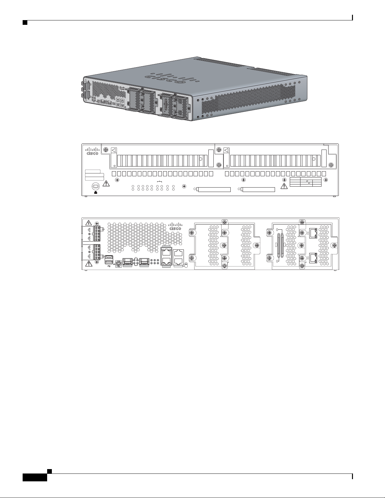
• Figure 1-1 shows the Cisco 2010 Connected Grid Router chassis.
• Figure 1-2 shows the power supply side view of the Cisco CGR 2010 router.
• Figure 1-3 shows the cable side panel of the Cisco CGR 2010 router.
OL-31454-01
Cisco 2010 Connected Grid Router Hardware Installation Guide
1-1
Page 18
Hardware Features
277398
PSU1 PSU2
PSU OK
PWR-150W-HV
PSU OK
PWR-150W-HV
SYS SPD SPD SPD SPD 2 0 1
USB
CON
ACT
SFP
0/1
EN
SFP
0/0
EN
GE
0/1
LINK
GE
0/0
LINK
PSU
231
CONSOLE
SLOT
CF1
DO NOT REMOVE DURING
NETWORK OPERATION
CF0
DO NOT REMOVE DURING
NETWORK OPERATION
Cisco Connected Grid Router 2000 Series
PS Type
LoV dc
HiV dc
V ac, 50/60 Hz
10A
2A
2A
Input Rating Per Sources
24-60V
100-270V
100-240V ~
CAUTION: This unit may have more than
one power source. Disconnect all power
sources before servicing to avoid
electric shock.
277397
SFP 0/0
GE 0/0
GE 0/1
SFP 0/1
CONSOLE
PSU2
L
N
N
L
+
Lo
-
-
Lo
+
-
HI
+
+
HI
-
Cisco CGR 2010
0
1
EN
EN
SPD
CF1PS
2ACT
SYS 0 1
SL
SL
AUX
EN
SLOT 3 SLOT 2 SLOT 1 SLOT 0
CONN CONN
0-3
4-7
GRWIC–8A/8-232
GRWIC–2CE1T1-PRI
CD/LP AL CD/LP AL
P1 P0
PSU1
Figure 1-1 Cisco CGR 2010 Router Chassis
Cisco CGR 2010
L
-
N
HI
+
PSU2PSU1
+
Lo
-
-
Lo
+
+
N
HI
L
-
1
0
EN
SL
EN
CF
PS
ACT
1
2
SFP 0/0
SFP 0/1
SPD
SYS 0
1
SL
Figure 1-2 Power Supply Side View of the Cisco CGR 2010 Router
SLOT 3 SLOT 2
GE 0/1
AUX
GE 0/0
CONSOLE
EN
SLOT 1 SLOT 0
CONN CONN
0-3
4-7
CD/LP AL CD/LP AL
P1 P0
Chapter 1 Overview of the Router
277400
Figure 1-3 Cable Side View of the Cisco CGR 2010 Router
Hardware Features
This section describes the hardware features in Cisco CGR 2010 router.
• Locating Chassis Features and Functions, page 1-3
• Built-in Interface Ports, page 1-5
• Removable and Interchangeable Modules and Cards, page 1-6
• Real-Time Clock, page 1-8
1-2
Cisco 2010 Connected Grid Router Hardware Installation Guide
OL-31454-01
Page 19
Chapter 1 Overview of the Router
248945
PSU1 PSU2
PSU OK
PWR-150W-HV
PSU OK
PWR-150W-HV
SYS SPD SPD SPD SPD 2 0 1
USB
CON
ACT
SFP
0/1
EN
SFP
0/0
EN
GE
0/1
LINK
GE
0/0
LINK
PSU
231
CONSOLE
SLOT
CF1
DO NOT REMOVE DURING
NETWORK OPERATION
CF0
DO NOT REMOVE DURING
NETWORK OPERATION
Cisco Connected Grid Router 2000 Series
CAUTION: This unit may have more than
one power source. Disconnect all power
sources before servicing to avoid
electric shock.
PS
Type
Input Terminal
Symbol
Input Rating
Per Source
Lo V DC
Hi V DC
Lo 24 - 60 V 10A
100-250V
2A
100-240V
~
2A
50-60 Hz
Hi
or
V AC
~
1
2
3 4
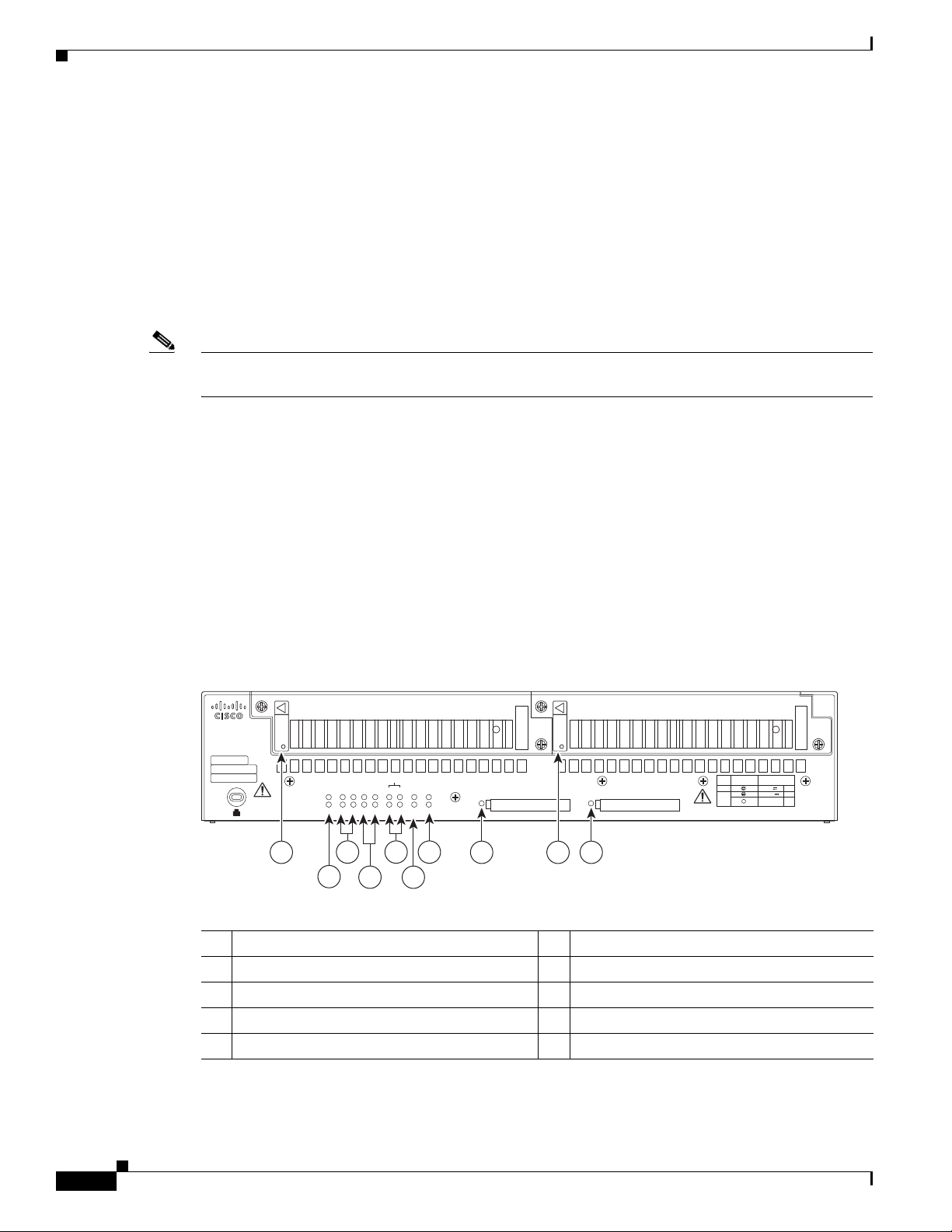
Locating Chassis Features and Functions
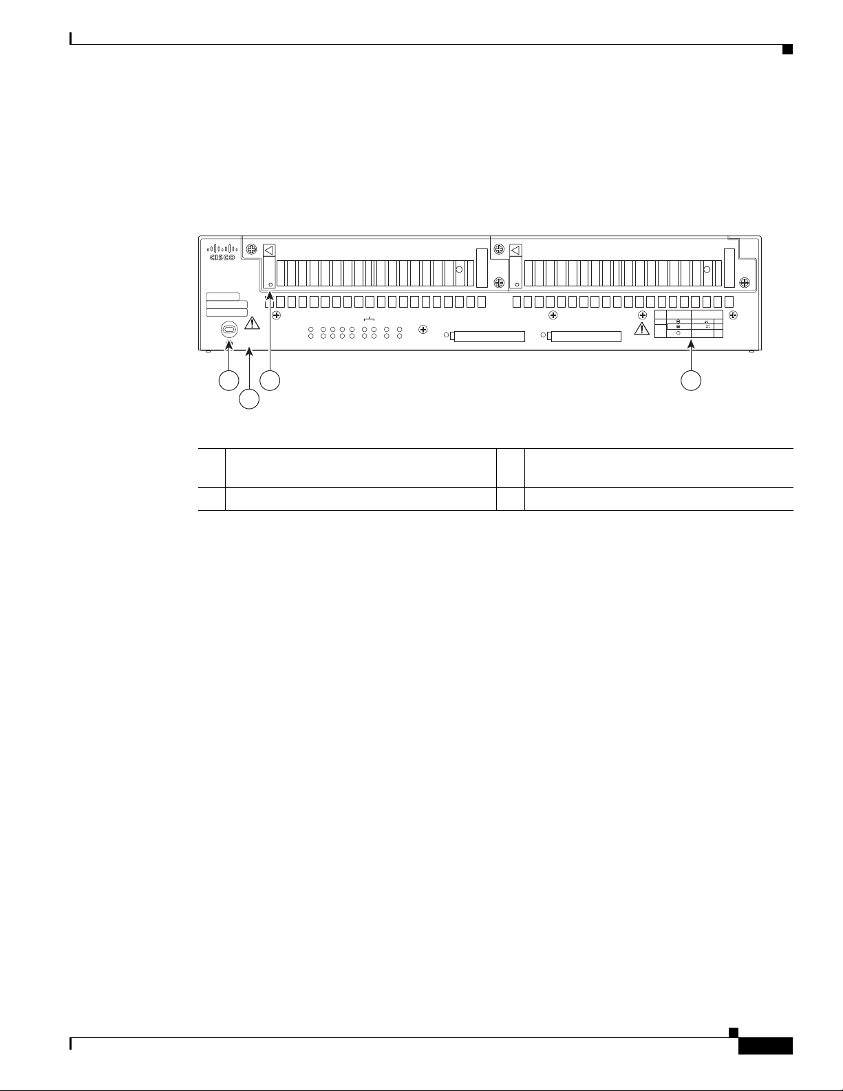
Figure 1-4 shows the different chassis features and functions available on the power supply side view of
the Cisco CGR 2010 router. Figure 1-5 shows the different chassis features and functions available on
the cable side view of the Cisco CGR 2010 router.
Figure 1-4 Power Supply Side View Features and Functions on the Cisco CGR 2010 Router
Hardware Features
1 Kensington security slot 2 Caution label and statement for multiple
power source
3 Power supply unit 1 (PSU1) label 4 Power supply power range label
OL-31454-01
Cisco 2010 Connected Grid Router Hardware Installation Guide
1-3
Page 20

Hardware Features
SFP 0/0
GE 0/0
GE 0/1
SFP 0/1
CONSOLE
PSU2
L
N
N
L
+
Lo
-
-
Lo
+
-
HI
+
+
HI
-
Cisco CGR 2010
0
1
EN
EN
SPD
CF1PS
2ACT
SYS 0 1
SL
SL
AUX
EN
SLOT 3 SLOT 2 SLOT 1 SLOT 0
CONN CONN
0-3
4-7
GRWIC–8A/8-232
GRWIC–2CE1T1-PRI
CD/LP AL CD/LP AL
P1 P0
PSU1
GE 0/0
GE 0/1
CONSOLE
1PS2
01
SL
SL
AUX
EN
1 65
2 3 7 98
4
277445
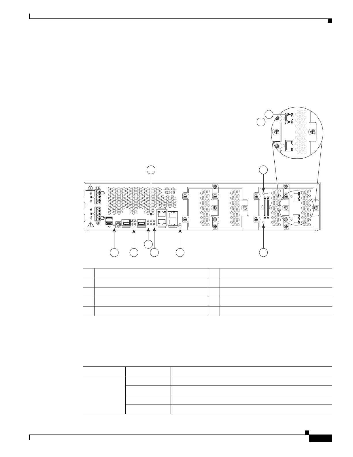
Chapter 1 Overview of the Router
Figure 1-5 Cable Side View Features and Functions on the Cisco CGR 2010 Router
1 Terminal blocks
3 USB
2
serial console port
5 100/1000 Ethernet port (GE0/0 and GE0/1) 6 RJ-45 aux port and serial console port
7 GRWIC slot 3 (slot cover showing) 8 GRWIC slot 2 (slot cover showing)
9 GRWIC slot 1 (8-port dual RS-232 serial
interface showing)
1. Enables AC power, high-voltage DC power, and low-voltage DC power input for dual power supplies.
2. USB = Universal serial bus.
3. GRWIC slots 0, 1, 2, and 3 (slot 0 is on the far right).
4. For T1/E1 interfaces, shielded cables are required to meet EN55022, Cispr 22, and EN300-386 compliance.
GRWIC Installation Options
The CGR 2010 router’s four slots with two removable dividers allow the following GRWIC installation
options:
• 4 single-wide GRWICs
• 2 single-wide GRWICs and 1 double-wide GRWIC
• 2 double-wide GRWICs
1
2 USB0 and USB1 (1, top)
4 SFP0/0 and SFP0/1
10 GRWIC slot 0
showing)
3
(T1/E1 dual port interface
4
1-4
Cisco 2010 Connected Grid Router Hardware Installation Guide
OL-31454-01
Page 21
Chapter 1 Overview of the Router
Built-in Interface Ports
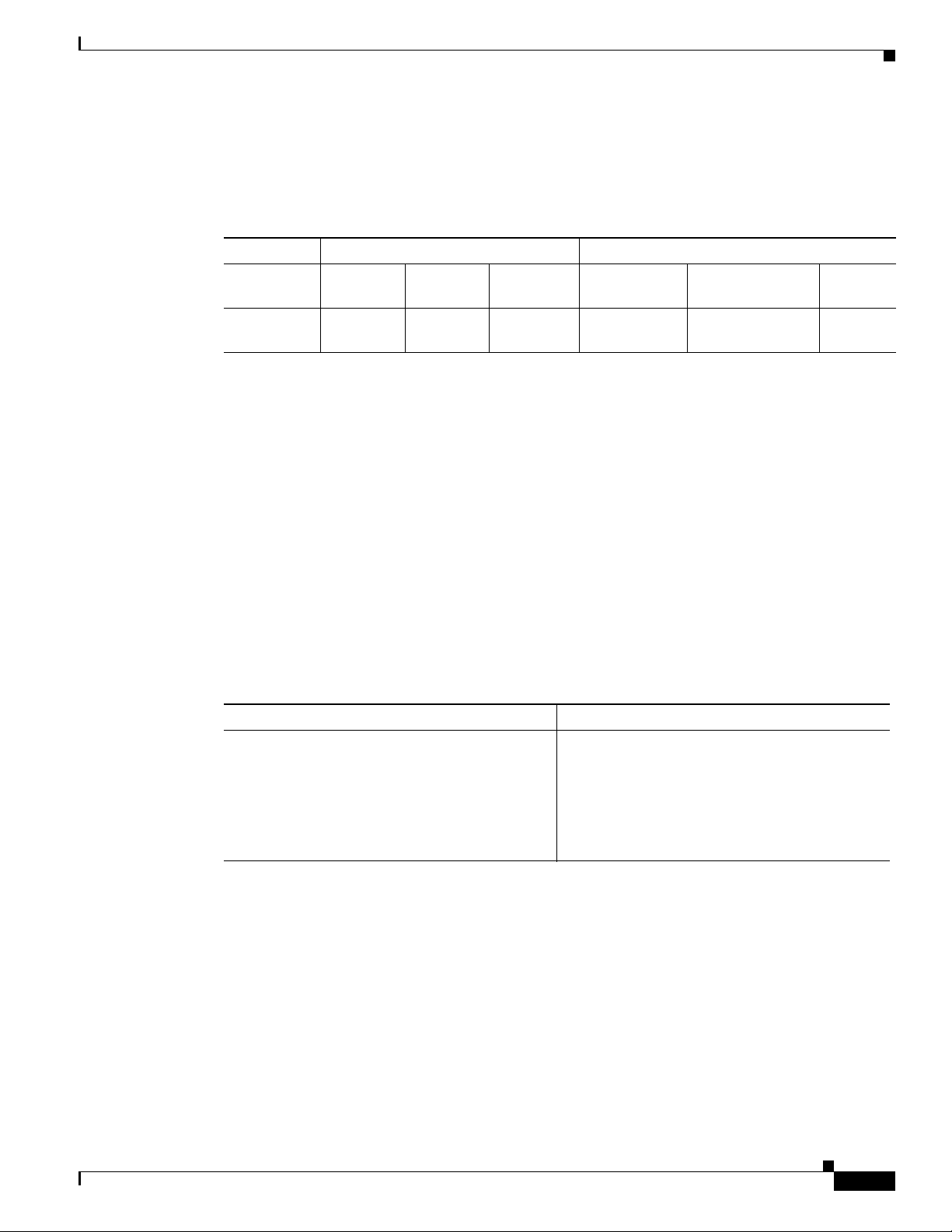
Table 1- 1 summarizes the interface ports built into the router chassis.
Table 1-1 Summary of Cisco CGR 2010 Built-In Interfaces
Router
Model
Cisco CGR
2010
Gigabit Ethernet Ports
There are two different types of Gigabit Ethernet ports available on Cisco CGR 2010 router.
• Gigabit Ethernet Ports, page 1-5
• SFP Ports, page 1-5
Hardware Features
Data Ports Management Ports
10/100/1000
GE RJ-45
222 1 1 1
100/1000
SFP USB Type A
Console,
Serial, RJ-45
Console,
Mini-USB (Type B)
Auxiliary,
RJ-45
Gigabit Ethernet Ports
SFP Ports
The Gigabit Ethernet RJ-45 copper interface ports support 100BASE-TX and 1000BASE-T.
The small form factor pluggable (SFP) ports on the Cisco CGR 2010 router support the SFP modules
listed in Table 1-2.
Table 1-2 Supported SFP Modules
Type of SFP Module Model
Rugged and Industrial SFPs
-40 to 140°F (-40 to 60°C)
• GLC-SX-MM-RGD
• GLC-LX-SM-RGD
• GLC-ZX-SM-RGD
• GLC-FE-100LX-RGD
• GLC-FE-100FX-RGD
OL-31454-01
Cisco 2010 Connected Grid Router Hardware Installation Guide
1-5
Page 22

Hardware Features
Table 1-2 Supported SFP Modules (continued)
Type of SFP Module Model
Commercial SFPs
32 to 113°F (0 to 45°C)
Extended temperature SFPs
23 to 140°F (-5 to 60°C)
• GLC-BX-U with digital optical monitoring
• GLC-BX-D with DOM support
• GLC-FE-100LX
• GLC-FE-100BX-D
• GLC-FE-100BX-U
• GLC-FE-100FX
• GLC-FE-100EX
• GLC-FE-100ZX
• CWDM-SFP with DOM support
• SFP-GE-S with DOM support
• SFP-GE-L with DOM support
Chapter 1 Overview of the Router
(DOM) support
• SFP-GE-Z with DOM support
The SFP port shares the same physical port as an RJ-45 GE port. The SFP port can be configured for the
following behaviors:
• Always use the RJ-45 port.
• Always use the SFP port.
USB Console Port
The Mini-USB type B port has been enabled to perform management tasks on the router. To use this port,
you must install a Windows USB device driver before establishing physical connectivity between a
personal computer and the router. See the “Installing the Cisco Microsoft Windows USB Device Driver”
section on page 3-21 for driver installation instructions.
Removable and Interchangeable Modules and Cards
GRWICs and power supply units (PSU) for the Cisco CGR 2010 fit into external slots and can be
removed or replaced without opening the chassis.
Note See Installing Cisco Interface Cards in Cisco Access Routers document at:
http://www.cisco.com/en/US/docs/routers/access/interfaces/ic/hardware/installation/guide/inst_ic.html
for instructions that describe how to install GRWICs in the router.
Grid Router WAN Interface Cards
GRWICs are the latest generation of interface cards. GRWICs are installed in the GRWIC slots on the
router (see Figure 5-7 on page 5-10).
Cisco 2010 Connected Grid Router Hardware Installation Guide
1-6
OL-31454-01
Page 23
Chapter 1 Overview of the Router
The router can accommodate four single-wide GRWICS, or two single-wide GRWICs and one
double-wide GRWIC, or two double-wide GRWICs at any one time. See “Installing Grid Router WAN
Interface Cards” section on page 5-9.
Memory
Cisco CGR 2010 routers contain the following types of memory:
• DDR2—Stores the running configuration and routing tables, and is used for packet buffering by the
• Boot/NVRAM—Stores the bootstrap program (ROM monitor), the configuration register, and the
• Flash memory—External flash memory. Stores the operating system software image. Supports two
• Two 1-GB USB flash memory sticks (MEMUSB-1024FT), one each in drives USB 0 and USB 1.
Power Supplies
Hardware Features
network interfaces. Cisco IOS software executes from DRAM memory. Supports 1-GB on board
DDR2.
startup configuration.
external 4 GB I-temp compact flash memory cards.
Cisco CGR 2010 supports three PSUs (power supply units). Power supplies are field replaceable,
externally accessible, and hot swappable.
The three power supply options are summarized in Tabl e 1 -3 :
Table 1-3 Power-Supply Modules
Model Description
PWR-RGD-AC-DC High-voltage AC or DC power supply.
PWR-RGD-LOW-DC Low-voltage DC power supply.
PWR-RGD-AC-DC-C High-voltage AC or DC power supply. China-specific model.
Note Any combination of power supplies can be inserted into the chassis. Dual power supply configurations
are load sharing in redundancy mode. A single power supply is sufficient for supporting power needs to
the system.
Caution Two types of power supplies are supported on the Cisco CGR 2010 router: a low-voltage DC power
supply and a high-voltage DC/AC power supply. Take caution when selecting the correct input voltage
for the power supply installed or damage will result. For details on connecting AC and DC power
supplies, see the “Power-Supply Modules” section on page 3-8.
OL-31454-01
Table 1- 4 summarizes the power options.
Table 1-4 Cisco CGR 2010 Power Options
Router AC AC + POE DC Hot Swap Internal RPS
1
Dual DC
CGR 2010 Yes No Yes Yes Yes No
Cisco 2010 Connected Grid Router Hardware Installation Guide
2
1-7
Page 24
Slot, Port, and Interface Information
277566
PSU1 PSU2
PSU OK
PWR-150W-HV
PSU OK
PWR-150W-HV
SYS SPD SPD SPD SPD 2 0 1
USB
CON
ACT
SFP
0/1
EN
SFP
0/0
EN
GE
0/1
LINK
GE
0/0
LINK
PSU
231
CONSOLE
SLOT
CF1
DO NOT REMOVE DURING
NETWORK OPERATION
CF0
DO NOT REMOVE DURING
NETWORK OPERATION
Cisco Connected Grid Router 2000 Series
CAUTION: This unit may have more than
one power source. Disconnect all power
sources before servicing to avoid
electric shock.
PS
Type
Input Terminal
Symbol
Input Rating
Per Source
Lo V DC
Hi V DC
Lo 24 - 60 V
10A
100-250V
2A
100-240V
~
2A
50-60 Hz
Hi
or
V AC
~
1 98
2
10
6
7
3
4
5
1. Internal RPS means that additional power supply can be added to the PS2 slot.
2. Dual DC means two separate DC inputs to the same power supply.
Real-Time Clock
Upon system power up, the internal real-time clock with battery backup provides the system software
with time of day. This allows the system to verify the validity of the certification authority (CA)
certificate. The Cisco CGR 2010 has a lithium battery. This battery lasts the life of the router under the
operating environmental conditions specified for the router and is not field-replaceable.
Note If the lithium battery in a Cisco CGR 2010 router should fail, the router must be returned to Cisco for
repair.
Slot, Port, and Interface Information
Chapter 1 Overview of the Router
On the Cisco CGR 2010 router, the numbering format for slots and ports is defined as follows:
interface type 0/slot/port. “0” indicates slots that are built into the chassis of a router.
LED Indicators
Figure 1-6 summarizes the LED indicators that are located on the router bezel or chassis, but not on the
removable interface cards.
Figure 1-6 Power Supply Side View LEDs on the Cisco CGR 2010 Router
1 PSU1 OK LED
3 SFP0/14 EN5 SPD6 LEDs 4 GE0/17 LNK8 and SPD LED
5 SLOT LEDs (slots 0 through 3) 6 Console/USB connection LEDs
7 PSU1/2 LEDs 8 Compact flash slot 1 LED
9 PSU OK LED 10 Compact flash slot 0 LED
Cisco 2010 Connected Grid Router Hardware Installation Guide
1-8
1. PSU = Power supply unit
2. ACT = Activity
2 ACT2 and SYS3 LEDs
OL-31454-01
Page 25
Chapter 1 Overview of the Router
GRWIC–2CE1T1-PRI
CD/LP AL CD/LP AL
P1 P0
3. SYS = System
4. SFP = Small form-factor pluggable module slots 0 and 1
5. EN = Enable
6. SPD = Speed
7. GE = Gigabit Ethernet slots 0 and 1
8. LNK = Link
Figure 1-7 Cable Side View LEDs on the Cisco CGR 2010 Router
LED Indicators
9
10
4
Cisco CGR 2010
-
L
HI
N
+
PSU2
+
Lo
-
-
Lo
+
PSU1
+
N
HI
L
1
-
0
EN
SFP 0/0
EN
SFP 0/1
SPD
CF1PS
SYS 0 1
SL
GE 0/1
2ACT
GE 0/0
SL
AUX
CONSOLE
EN
SLOT 3 SLOT 2 SLOT 1 SLOT 0
7
CONN CONN
0-3
GRWIC–8A/8-232
P1 P0
4-7
GRWIC–2CE1T1-PRI
CD/LP AL CD/LP AL
3
1
2 5
6 8
1 EN (enable USB console) 2 SFP1 EN and SPD LEDs
3 ACT status and SYS status LEDs 4 Compact flash 0 and 1 (0, bottom, 1, top)
5 PSU1 (bottom), PSU2 (top) 6 EN (enable RJ-45 console)
7 GRWIC serial interface CONN LED 8 GRWIC serial interface CONN LED
9 Dual-port T1/E1 GRWIC CD/LP LED 10 Dual-port T1/E1 GRWIC AL LED
1. SFP = Small form factor pluggable.
For LED troubleshooting information, including possible trouble causes and corrective actions, see
Table 1- 5 and Tab l e 1-6 below.
277567
Table 1-5 Cisco CGR 2010 LED Indicators — Cable Side
LED Color Description
SYS Solid green Solid green indicates normal operation.
Blinking green System is booting or is in ROM monitor mode.
Amber System error.
OL-31454-01
Off Power is off or system board is faulty.
Cisco 2010 Connected Grid Router Hardware Installation Guide
1-9
Page 26

LED Indicators
Table 1-5 Cisco CGR 2010 LED Indicators — Cable Side
LED Color Description
ACT Solid or blinking
green
Off No packet transfers are occurring.
CF 0
Green Flash memory is being accessed; do not eject the compact flash
CF 1
Amber Compact flash error.
Off Flash memory is not being accessed; okay to eject the compact
PSU 1
PSU 2
Green Valid output.
Red Invalid output.
Blinking red Invalid input
CONSOLE EN
Green Serial console is active.
(RJ-45)
USB CON Green USB console is active.
SFP 0/0 EN
SFP 0/1 EN
Off Not present.
Green Present and enabled.
Amber Present with failure.
SFP 0/0 SPD
SFP 0/1 SPD
Off No link.
blinking Blink frequency indicates port speed:
Solid or blinking indicates packet activity between the forwarding
and routing engine and any I/O port.
memory card.
flash memory card.
Chapter 1 Overview of the Router
2 blinks before pause – 100Mbps link speed.
3 blinks before pause – 1000Mbps link speed.
Table 1-6 Cisco CGR 2010 LED Indicators — Power Supply Side
LED Color Description
SYS Solid green Solid green indicates normal operation.
Blinking green System is booting or is in ROM monitor mode.
Amber System error.
Off Power is off or system board is faulty.
ACT Solid or blinking
green
Solid or blinking indicates packet activity between the forwarding
and routing engine and any I/O port.
Off No packet transfers are occurring.
PSU 1
PSU 2
Green Valid output.
Red Invalid output.
Blinking red Invalid input
1-10
Cisco 2010 Connected Grid Router Hardware Installation Guide
OL-31454-01
Page 27

Chapter 1 Overview of the Router
Table 1-6 Cisco CGR 2010 LED Indicators (continued)— Power Supply Side
LED Color Description
CF 0
CF 1
CONSOLE EN
(RJ-45)
USB CON Green USB console is active.
SLOT 0
SLOT 1
SLOT 2
SLOT 3
SFP 0/0 EN
SFP 0/1 EN
SFP 0/0 SPD
SFP 0/1 SPD
Specifications
Green Flash memory is being accessed; do not eject the compact flash
memory card.
Amber Compact flash error.
Off Flash memory is not being accessed; okay to eject the compact
flash memory card.
Green Serial console is active.
Green GRWIC is active.
Amber GRWIC is not active.
Off Not present.
Green Present and enabled.
Amber Present with failure.
Off No link.
blinking Blink frequency indicates port speed:
GE 0/0 LINK
GE 0/1: LINK
GE 0/0 SPD
GE 0/1 SPD
Specifications
To view specifications for the Cisco CGR 2010 router, see the Cisco 2010 Connected Grid Router data
sheet at:
http://www.cisco.com/en/US/prod/collateral/routers/ps10967/ps10977/data_sheet_c78_593509.html
2 blinks before pause – 100Mbps link speed.
3 blinks before pause – 1000Mbps link speed.
Green Solid green indicates the Ethernet port has a link partner.
Off No link.
blinking Blink frequency indicates port speed:
2 blinks before pause – 100Mbps link speed.
3 blinks before pause – 1000Mbps link speed.
OL-31454-01
Cisco 2010 Connected Grid Router Hardware Installation Guide
1-11
Page 28

Specifications
Chapter 1 Overview of the Router
1-12
Cisco 2010 Connected Grid Router Hardware Installation Guide
OL-31454-01
Page 29

CHAP T E R
2
Preparing for Router Installation
This document provides preinstallation information, such as recommendations and requirements that
should be met prior to installing your router. See the following sections to prepare for installation.
• Safety Recommendations, page 2-2
• General Site Requirements, page 2-4
• Rack Requirements, page 2-4
• Router Environmental Requirements, page 2-4
• Power Guidelines and Requirements, page 2-5
• Required Tools and Equipment for Installation and Maintenance, page 2-9
• Installation Checklist, page 2-10
• Creating a Site Log, page 2-10
Note To see translated warnings that appear in this publication, see the Cisco Connected Grid Routers Series
Regulatory Compliance and Safety Information document.
Warning
Warning
Warning
Warning
Only trained and qualified personnel should be allowed to install, replace, or service this equipment.
Statement 1030
Ultimate disposal of this product should be handled according to all national laws and regulations.
Statement 1040
This equipment must be installed and maintained by service personnel as defined by AS/NZS 3260.
Incorrectly connecting this equipment to a general-purpose outlet could be hazardous. The
telecommunications lines must be disconnected 1) before unplugging the main power connector or 2)
while the housing is open, or both.
This unit might have more than one power supply connection. All connections must be removed to
de-energize the unit.
Statement 1028
Statement 1043
OL-31454-01
Cisco 2010 Connected Grid Router Hardware Installation Guide
2-1
Page 30

Safety Recommendations
Chapter 2 Preparing for Router Installation
Warning
Warning
Warning
Warning
Warning
Warning
This product relies on the building’s installation for short-circuit (overcurrent) protection. Ensure that
the protective device is rated not greater than: Maximum 15 A, 120 Vac or Maximum 10 A, 230 Vac
Statement 1005
Take care when connecting units to the supply circuit so that wiring is not overloaded.
Hazardous network voltages are present in WAN ports regardless of whether power to the unit is OFF
or ON. To avoid electric shock, use caution when working near WAN ports. When detaching cables,
detach the end away from the unit first.
Installation of the equipment must comply with local and national electrical codes.
This unit is intended for installation in restricted access areas. A restricted access area can be
accessed only through the use of a special tool, lock and key, or other means of security.
Statement 1017
Blank faceplates and cover panels serve three important functions: they prevent exposure to
hazardous voltages and currents inside the chassis; they contain electromagnetic interference (EMI)
that might disrupt other equipment; and they direct the flow of cooling air through the chassis. Do not
operate the system unless all cards, faceplates, front covers, and rear covers are in place.
Statement 1029
Statement 1026
Statement 1018
Statement 1074
Safety Recommendations
Follow these guidelines to ensure general safety:
• Keep the chassis area clear and dust-free during and after installation.
• Keep tools and chassis components away from walk areas.
• Do not wear loose clothing that could get caught in the chassis. Fasten your tie or scarf and roll up
your sleeves.
• Wear safety glasses when working under conditions that might be hazardous to your eyes.
• Do not perform any action that creates a hazard to people or makes the equipment unsafe.
Cisco 2010 Connected Grid Router Hardware Installation Guide
2-2
OL-31454-01
Page 31

Chapter 2 Preparing for Router Installation
Safety with Electricity
Follow these guidelines when working on equipment powered by electricity:
• Locate the emergency power-off switch in the room in which you are working. If an electrical
accident occurs, you can quickly turn off the power.
• Disconnect all power before doing the following:
–
Installing or removing a chassis
–
Working near power supplies
• Look carefully for possible hazards in your work area, such as moist floors, ungrounded power
extension cables, frayed power cords, and missing safety grounds.
• Do not work alone if hazardous conditions exist.
• Never assume that power is disconnected from a circuit. Always check.
• Never open the enclosure of the router’s internal power supply.
• If an electrical accident occurs, proceed as follows:
–
Use caution; do not become a victim yourself.
–
Turn off power to the device.
–
If possible, send another person to get medical aid. Otherwise, assess the victim’s condition and
then call for help.
Safety Recommendations
–
Determine if the person needs rescue breathing or external cardiac compressions; then take
appropriate action.
Warning
Warning
Warning
This unit might have more than one power supply connection. All connections must be removed to
de-energize the unit.
Do not work on the system or connect or disconnect cables during periods of lightning activity.
Statement 1001
Read the installation instructions before connecting the system to the power source.
Statement 1028
Preventing Electrostatic Discharge Damage
Electrostatic discharge (ESD) can damage equipment and impair electrical circuitry. It can occur if
electronic printed circuit cards are improperly handled and can cause complete or intermittent failures.
Always follow ESD prevention procedures when removing and replacing modules:
• Ensure that the router chassis is electrically connected to earth ground.
• Wear an ESD-preventive wrist strap, ensuring that it makes good skin contact. Connect the clip to
an unpainted surface of the chassis frame to channel unwanted ESD voltages safely to ground. To
guard against ESD damage and shocks, the wrist strap and cord must operate effectively.
Statement 1004
OL-31454-01
• If no wrist strap is available, ground yourself by touching a metal part of the chassis.
Cisco 2010 Connected Grid Router Hardware Installation Guide
2-3
Page 32

General Site Requirements
Caution For the safety of your equipment, periodically check the resistance value of the antistatic strap. It should
be between 1 and 10 megohms (Mohm).
General Site Requirements
This section describes the requirements your site must meet for safe installation and operation of your
router. Ensure that the site is properly prepared before beginning installation. If you are experiencing
shutdowns or unusually high errors with your existing equipment, this section can also help you isolate
the cause of failures and prevent future problems.
Rack Requirements
The following information will help you plan your equipment rack configuration:
• Allow clearance around the rack for maintenance.
• Allow at least one rack unit of vertical space between routers.
• Enclosed racks must have adequate ventilation. Ensure that the rack is not congested, because each
router generates heat. An enclosed rack should have louvered sides and a fan to provide cooling air.
Heat generated by equipment near the bottom of the rack can be drawn upward into the intake ports
of the equipment above.
Chapter 2 Preparing for Router Installation
Router Environmental Requirements
Mount the Cisco CGR 2010 routers in a rack. The location of your router and the layout of your
equipment rack or wiring room are extremely important considerations for proper operation. Equipment
placed too close together, inadequate ventilation, and inaccessible panels can cause malfunctions and
shutdowns, and can make maintenance difficult. Plan for access to both power supply side and cable side
panels of the router.
Note Allow at least one rack unit of vertical space above the router.
When planning your site layout and equipment locations, refer to the “General Site Requirements”
section on page 2-4, section. If you are currently experiencing shutdowns or an unusually high number
of errors with your existing equipment, these precautions and recommendations may help you isolate the
cause of failure and prevent future problems.
• Ensure that the room where your router operates has adequate air circulation. Electrical equipment
generates heat. Without adequate air circulation, ambient air temperature may not cool equipment
to acceptable operating temperatures.
• Always follow ESD-prevention procedures described in the “Preventing Electrostatic Discharge
Damage” section on page 2-3 to avoid damage to equipment. Damage from static discharge can
cause immediate or intermittent equipment failure.
• Ensure that the chassis cover and module cable side panels are secure. All empty interface card slots
and power supply bays must have filler panels installed.
2-4
Cisco 2010 Connected Grid Router Hardware Installation Guide
OL-31454-01
Page 33

Chapter 2 Preparing for Router Installation
• When equipment installed in a rack (particularly in an enclosed rack) fails, try operating the
equipment by itself, if possible. Power off other equipment in the rack (and in adjacent racks) to
allow the router under test a maximum of cooling air and clean power.
Power Guidelines and Requirements
Check the power at your site to ensure that you are receiving “clean” power (free of spikes and noise).
Install a power conditioner if necessary.
The AC power supply includes the autoselect feature for either 110 V or 220 V operation.
Caution Two types of power supplies are supported on the Cisco CGR 2010: a low-voltage DC power supply and
a high-voltage DC/AC power supply. Take caution when selecting the correct input voltage for the power
supply installed or damage will result.
Network Cabling Specifications
Power Guidelines and Requirements
The following sections describe the cables needed to install your Cisco CGR 2010 router:
• Console and Auxiliary Port Considerations, page 2-5
• Preparing for Network Connections, page 2-6
Console and Auxiliary Port Considerations
The Cisco CGR 2010 router includes an asynchronous serial console port and an auxiliary port. The
console and auxiliary ports provide access to the router either locally using a console terminal connected
to the console port, or remotely using a modem connected to the auxiliary port. This section discusses
important cabling information to consider before connecting the router to a console terminal or modem.
The main difference between the console and auxiliary ports is that the auxiliary port supports hardware
flow control and the console port does not. Flow control paces the transmission of data between a
sending device and a receiving device. Flow control ensures that the receiving device can absorb the data
sent to it before the sending device sends more. When the buffers on the receiving device are full, a
message is sent to the sending device to suspend transmission until the data in the buffers has been
processed. Because the auxiliary port supports flow control, it is ideally suited for use with the
high-speed transmissions of a modem. Console terminals send data at slower speeds than modems;
therefore, the console port is ideally suited for use with console terminals.
Console Port Connections
The router has both EIA/TIA-232 asynchronous (RJ-45) and USB 5-pin mini Type B, 2.0 compliant
serial console ports. The console ports do not have any hardware flow control. Shielded USB cables with
properly terminated shields are recommended.
EIA/TIA-232 Port
OL-31454-01
Depending on the cable and the adapter used, this port appears as a DTE or DCE device at the end of the
cable. Only one port can be used at the same time.
Cisco 2010 Connected Grid Router Hardware Installation Guide
2-5
Page 34

Network Cabling Specifications
USB Serial Console Port
Note Always use shielded USB cables with a properly terminated shield.
Chapter 2 Preparing for Router Installation
The default parameters for the console port are 9600 baud, 8 data bits, no parity, and 1 stop bit. The
console port does not support hardware flow control. For detailed information about installing a console
terminal, see the “Connecting to a Console Terminal or Modem” section on page 3-17.
For cable and port pinouts, see Cisco Modular Access Router Cable Specifications.
The USB serial console port connects directly to the USB connector of a PC using a USB Type A to 5-pin
mini USB Type-B cable. The USB Console supports full speed (12Mb/s) operation. The console port
does not support hardware flow control.
The default parameters for the console port are 9600 baud, 8 data bits, no parity, and 1 stop bit. The
console port does not support mode control. For detailed information about installing a console terminal,
see the “Connecting to a Console Terminal or Modem” section on page 3-17.
For operation with Microsoft Windows, the Cisco Windows USB Console Driver must be installed on
every PC connected to the console port. If the driver is not installed, prompts guide you through a simple
installation process. For detailed information about installing the Cisco Windows USB Console Driver
see “Installing the Cisco Microsoft Windows USB Device Driver” section on page 3-21.
The Cisco Windows USB Console Driver allows plugging and unplugging the USB cable from the
console port without affecting Windows HyperTerminal operations. No special drivers are needed for
Mac OS X or Linux.
Only one console port can be active at a time. When a cable is plugged into the USB console port the
RJ-45 port becomes inactive. Conversely, when the USB cable is removed from the USB port, the RJ-45
port becomes active.
Baud rates for the USB console port are 1200, 2400, 4800, 9600, 19200, 38400, 57600, and 115200 bps.
Note 4-pin mini USB Type-B connectors are easily confused with 5-pin mini USB Type-B connectors.
They are not compatible. Only the 5-pin mini USB Type-B can be used.
Auxiliary Port Connections
The router has an EIA/TIA-232 asynchronous serial auxiliary port (RJ-45) that supports flow control.
Depending on the cable and the adapter used, this port appears as a DTE or DCE device at the end of the
cable.
Preparing for Network Connections
When setting up your router, consider distance limitations and potential electromagnetic interference
(EMI) as defined by the applicable local and international regulations.
Network connection considerations are provided for several types of network interfaces and are
described in the following sections:
• Ethernet Connections, page 2-7
2-6
• Serial Connections, page 2-7
Cisco 2010 Connected Grid Router Hardware Installation Guide
OL-31454-01
Page 35

Chapter 2 Preparing for Router Installation
See the following document for more information about network connections and interfaces:
• Cisco Modular Access Router Cable Specifications
Network Cabling Specifications
Warning
To avoid electric shock, do not connect safety extra-low voltage (SELV) circuits to telephone-network
voltage (TNV) circuits. LAN ports contain SELV circuits, and WAN ports contain TNV circuits. Some
LAN and WAN ports both use RJ-45 connectors.
Ethernet Connections
The IEEE has established Ethernet as standard IEEE 802.3. The Cisco CGR 2010 router supports the
following Ethernet implementations:
• 1000BASE-X—1000 Mb/s full-duplex transmission over a Category 5 or better unshielded
• 1000BASE-T—1000 Mb/s full-duplex transmission over a Category 5 or better unshielded
• 100BASE-TX—100 Mb/s full-duplex transmission over a Category 5 or better unshielded
See Cisco Modular Access Router Cable Specifications at www.cisco.com for information about
Ethernet cables, connectors, and pinouts.
Serial Connections
Statement 1021
twisted-pair (UTP) cable (IEEE 802.3z). Supports the Ethernet maximum length of 328 feet (100
meters).
twisted-pair (UTP) cable (IEEE 802.3ab). Supports the Ethernet maximum length of 328 feet (100
meters).
twisted-pair (UTP) cable (IEEE 802.3u). Supports the Ethernet maximum length of 328 feet (100
meters).
Serial connections are provided by the grid router WAN interface card (GRWIC). Before you connect a
device to a serial port, you need to know the following:
• Type of device, data terminal equipment (DTE) or data communications equipment (DCE), you are
connecting to the synchronous serial interface
• Type of connector, male or female, required to connect to the device
• Signaling standard required by the device
Configuring Serial Connections
The serial ports on the asynchronous/synchronous serial network modules and the serial grid router
WAN interface card use a GRWIC-8A/S cable with a DB-25 connector. Serial ports can be configured
as DTE or DCE, depending on the serial cable used.
Serial DTE or DCE Devices
A device that communicates over a synchronous serial interface is either a DCE or DTE device. A DCE
device provides a clock signal that paces the communications between the device and the router. A DTE
device does not provide a clock signal. DTE devices usually connect to DCE devices. The documentation
that accompanied the device should indicate whether it is a DTE or DCE device. (Some devices have a
jumper to select either DTE or DCE mode.) Tab le 2- 1 lists typical DTE and DCE devices.
OL-31454-01
Cisco 2010 Connected Grid Router Hardware Installation Guide
2-7
Page 36

Network Cabling Specifications
Table 2-1 Typical DTE and DCE Devices
Device Type Gender Typical Devices
DTE Male
DCE Female
1. If pins protrude from the base of the connector, the connector is male.
2. If the connector has holes to accept pins, the connector is female.
Signaling Standards Supported
The synchronous serial ports available for the router support the following signaling standards:
EIA/TIA-232 (EIA-323). You can order a Cisco DB-25 shielded serial transition cable that has the
appropriate connector for the standard you specify. The documentation for the device should indicate the
standard used for that device. The router end of the shielded serial transition cable has a DB-25
connector, which connects to the DB-25 port on a serial grid router WAN interface card. The other end
of the serial transition cable is available with a connector appropriate for the standard you specify. For
a list of the serial cables supported for GRWICs as well as the pinouts, see “Connectors and Cabling for
the 8-Port Asynchronous/ Synchronous RS-232 GRWIC” section on page 3-33.
The synchronous serial port can be configured as DTE or DCE, depending on the attached cable.
All serial ports configured as DTE require external clocking from a CSU/DSU or other DCE device.
Chapter 2 Preparing for Router Installation
1
2
Ter m i n a l
PC
Modem
CSU/DSU
Multiplexer
Distance Limitations
Serial signals can travel a limited distance at any given bit rate; generally, the slower the data rate, the
greater the distance. All serial signals are subject to distance limits, beyond which a signal significantly
degrades or is completely lost.
Table 2- 2 lists the recommended maximum speeds and distances for each serial interface type; however,
you might get good results at speeds and distances greater than those listed, if you understand the
electrical problems that might arise and can compensate for them. For instance, the recommended
maximum rate for V.35 is 2 Mb/s, but 4 Mb/s is commonly used.
Table 2-2 Serial Signal Transmission Speeds and Distances
Distance for
EIA/TIA-232
Distance for X.21 and
V.35 Distance for USB
Rate (bps) Feet Meters Feet Meters Feet Meters
2400 200 60 4100 1250 16.4 5
4800 100 30 2050 625 16.4 5
9600 50 15 1025 312 16.4 5
19200 25 7.6 513 156 16.4 5
38400 12 3.7 256 78 16.4 5
2-8
Cisco 2010 Connected Grid Router Hardware Installation Guide
OL-31454-01
Page 37

Chapter 2 Preparing for Router Installation
Table 2-2 Serial Signal Transmission Speeds and Distances (continued)
Required Tools and Equipment for Installation and Maintenance
Distance for
EIA/TIA-232
Distance for X.21 and
V.35 Distance for USB
Rate (bps) Feet Meters Feet Meters Feet Meters
56000 8.6 2.6 102 31 16.4 5
1544000 (T1) — — 50 15 16.4 5
Asynchronous/Synchronous Serial Module Baud Rates
The following baud-rate limitations apply to the slow-speed serial interfaces found in the
asynchronous/synchronous serial modules:
• Asynchronous interface—Maximum baud rate is 115.2 kbps.
• Synchronous interface—Maximum baud rate is 128 kbps full duplex.
Required Tools and Equipment for Installation and Maintenance
You need the following tools and equipment to install and upgrade the router and its components:
• ESD-preventive cord and wrist strap
• Number 2 Phillips screwdriver
• Phillips screwdrivers: small, 3/16-in. (4 to 5 mm) and medium, 1/4-in. (6 to 7 mm)
• Screws that fit your rack
In addition, depending on the type of modules you plan to use, you might need the following equipment
to connect a port to an external network:
• Cables for connection to the WAN and LAN ports (dependent on configuration).
Note For more information on cable specifications, see Cisco Modular Access Router Cable
Specifications at www.cisco.com.
• Ethernet hub or PC with a network interface card for connection to an Ethernet (LAN) port.
• Console terminal (an ASCII terminal or a PC running HyperTerminal or similar terminal emulation
software) configured for 9600 baud, 8 data bits, 1 stop bit, no flow control, and no parity.
• Modem for connection to the auxiliary port for remote administrative access (optional).
• Data service unit (DSU) or channel service unit/data service unit (CSU/DSU) as appropriate for
serial interfaces.
• External CSU for any CT1/PRI modules without a built-in CSU.
OL-31454-01
Cisco 2010 Connected Grid Router Hardware Installation Guide
2-9
Page 38

Installation Checklist
Installation Checklist
The sample installation checklist lists items and procedures for installing a new router. Make a copy of
this checklist and mark the entries when completed. Include a copy of the checklist for each router in
your site log (described in “Creating a Site Log” below).
Installation checklist for site_____________________________________________
Router name_______________________________________________________
Task Verified by Date
Installation checklist copied
Background information placed in Site Log
Site power voltages verified
Installation site power check completed
Required tools available
Additional equipment available
Router received
Product registration card received
www.cisco.com contact information label received
Chassis components verified
Initial electrical connections established
ASCII terminal (for local configuration) or
modem (for remote configuration) available
Signal distance limits verified
Startup sequence steps completed
Initial operation verified
Software image verified
Chapter 2 Preparing for Router Installation
Creating a Site Log
The Site Log provides a record of all actions related to the router. Keep it in an accessible place near the
chassis where anyone who performs tasks has access to it. Use the installation checklist to verify steps
in the installation and maintenance of the router. Site Log entries might include the following
information:
• Installation progress—Make a copy of the installation checklist and insert it into the site log. Make
entries as each procedure is completed.
• Upgrade and maintenance procedures—Use the site log as a record of ongoing router maintenance
and expansion history. A site log might include the following events:
–
Installation of GRWICs
–
Removal or replacement of GRWICs and other upgrades
–
Configuration changes
Cisco 2010 Connected Grid Router Hardware Installation Guide
2-10
OL-31454-01
Page 39

Chapter 2 Preparing for Router Installation
–
Maintenance schedules and requirements
–
Maintenance procedures performed
–
Intermittent problems
–
Comments and notes
Inspect all items for shipping damage. If anything appears to be damaged or you encounter problems
installing or configuring your router, contact Cisco customer service. Warranty, service, and support
information is in the quick start guide that shipped with your router.
Creating a Site Log
OL-31454-01
Cisco 2010 Connected Grid Router Hardware Installation Guide
2-11
Page 40

Creating a Site Log
Chapter 2 Preparing for Router Installation
2-12
Cisco 2010 Connected Grid Router Hardware Installation Guide
OL-31454-01
Page 41

CHAP T E R
3
Installing and Connecting the Router
This document describes how to install and connect Cisco CGR 2010 routers to a LAN or WAN, as well
as how to connect AC or DC power to the router. The following sections provide technical details.
• What you Need to Know, page 3-3
• Before You Begin, page 3-4
• Unpacking the Router, page 3-4
• Installing the Router in a Rack, page 3-5
• Power-Supply Modules, page 3-8
• Connecting to a Console Terminal or Modem, page 3-17
• Installing the Cisco Microsoft Windows USB Device Driver, page 3-21
• Uninstalling the Cisco Microsoft Windows USB Driver, page 3-22
• Connecting to the Auxiliary Port, page 3-24
• Connecting WAN and LAN Interfaces, page 3-25
• Auxiliary Port, Console Port, and Adapter Pinouts for the Cisco CGR 2010 Router, page 3-26
OL-31454-01
• Connectors and Cabling for the 8-Port Asynchronous/ Synchronous RS-232 GRWIC, page 3-33
Note To see translations of the warnings that appear in this publication, see Cisco Connected Grid Routers
Series Regulatory Compliance and Safety Information.
Caution For the optimum temperature ranges, do not operate it in an area that less than the minimum of 40°C and
exceeds a maximum recommended ambient temperature of 60°C.
Note To view specifications for the CGR 2010 router, see the Cisco 2010 Connected Grid Router data sheet at:
http://www.cisco.com/en/US/prod/collateral/routers/ps10967/ps10977/data_sheet_c78_593509.html
Warning
Only trained and qualified personnel should be allowed to install, replace, or service this equipment.
Statement 1030
Cisco 2010 Connected Grid Router Hardware Installation Guide
3-1
Page 42

Chapter 3 Installing and Connecting the Router
Warning
Warning
Warning
Warning
Warning
This unit might have more than one power supply connection. All connections must be removed to
de-energize the unit.
Statement 1028
Hazardous network voltages are present in WAN ports regardless of whether power to the unit is OFF
or ON. To avoid electric shock, use caution when working near WAN ports. When detaching cables,
detach the end away from the unit first.
Statement 1026
Do not use this product near water; for example, near a bath tub, wash bowl, kitchen sink or laundry
tub, in a wet basement, or near a swimming pool.
Statement 1035
Avoid using a telephone (other than a cordless type) during an electrical storm. There may be a remote
risk of electric shock from lightning.
Statement 1038
This unit is intended for installation in restricted access areas. A restricted access area can be
accessed only through the use of a special tool, lock and key, or other means of security.
Statement 1017
Warning
Warning
Warning
Warning
Warning
Stability hazard. The rack stabilizing mechanism must be in place, or the rack must be bolted to the
floor before you slide the unit out for servicing. Failure to stabilize the rack can cause the rack to tip
over.
Statement 1048
The chassis should be mounted on a rack that is permanently affixed to the building.
Statement 1049
Blank faceplates and cover panels serve three important functions: they prevent exposure to
hazardous voltages and currents inside the chassis; they contain electromagnetic interference (EMI)
that might disrupt other equipment; and they direct the flow of cooling air through the chassis. Do not
operate the system unless all cards, faceplates, front covers, and rear covers are in place.
Statement 1029
A ground wire must always be a single piece of wire. Never splice two wires together for a ground.
Corrosion and weathering can lead to a poor connection at the splice, making the ground ineffective
and dangerous.
To reduce the risk of fire, use only No. 26 AWG or larger telecommunication line cord.
Statement 270
Statement 1023
3-2
Warning
Cisco 2010 Connected Grid Router Hardware Installation Guide
Use copper conductors only.
Statement 1025
OL-31454-01
Page 43

Chapter 3 Installing and Connecting the Router
What you Need to Know
Warning
Warning
Warning
Warning
Caution Heat sinks applicable to warning statement 1079, can exceed 90º C in a 60º C ambient. Suitable
A readily accessible two-poled disconnect device must be incorporated in the fixed wiring.
1022
Invisible laser radiation may be emitted from the end of the unterminated fiber cable or connector. Do
not view directly with optical instruments. Viewing the laser output with certain optical instruments
(for example, eye loupes, magnifiers, and microscopes) within a distance of 100 mm may pose an eye
hazard.
To prevent the system from overheating, do not operate it in an area that exceeds the maximum
recommended ambient temperature of: 60°C (140°F).
Hot surface.
Statement 1056
Statement 1047
Statement 1079
precautions should be taken to avoid burns.
Warning
This equipment needs to be grounded. Use a green and yellow 12 to 14 AWG ground wire to connect
the host to earth ground during normal use.
Statement 242
Statement
What you Need to Know
CLI Console Access
Use the new USB console port on the router to access the Cisco Internet Operating System (IOS)
Command Line Interface (CLI) on the router and perform configuration tasks. A terminal emulation
program, such as Microsoft Windows HyperTerminal, is required to establish communication between
the router and a PC. See the “Connecting to a Console Terminal or Modem” section on page 3-17 for
instructions
Note A Microsoft Windows USB driver must be installed before you establish physical connectivity
between the router and the PC.
Slot and Port Numbers
Cisco CGR 2010 routers have built-in ports and new slots. The new slots accommodate new
grid router WAN interface cards (GRWICs). See the “Slot, Port, and Interface Information” section on
page 1-8 for slot and port numbering
OL-31454-01
Cisco 2010 Connected Grid Router Hardware Installation Guide
3-3
Page 44

Before You Begin
Before You Begin
Before installing and connecting a Cisco CGR 2010 router, read the safety warnings and gather the
following tools and equipment:
• ESD-preventive cord and wrist strap
• Number 2 Phillips screwdriver
• Flat-blade screwdrivers: small, 3/16-in. (4 to 5 mm) and medium, 1/4-in. (6 to 7 mm)
–
To install or remove GRWICs
–
To remove the cover, if you are upgrading memory or other components
• Screws that fit your rack
In addition, depending on the type of modules you plan to use, you might need the following equipment
to connect a port to an external network:
• Cables for connection to the WAN and LAN ports (dependent on configuration).
Note For more information on cable specifications, see Cisco Modular Access Router Cable
Chapter 3 Installing and Connecting the Router
Specifications on www.cisco.com.
• Ethernet hub or PC with a network interface card for connection to an Ethernet (LAN) port.
• Console terminal (an ASCII terminal or a PC running HyperTerminal or similar terminal emulation
software) configured for 9600 baud, 8 data bits, 1 stop bit, no flow control, and no parity.
• Modem for connection to the auxiliary port for remote administrative access (optional).
• Data service unit (DSU) or channel service unit/data service unit (CSU/DSU) as appropriate for
serial interfaces.
• External CSU for any CT1/PRI modules without a built-in CSU.
• NT1 device for ISDN BRI S/T interfaces (if not supplied by your service provider).
Caution Sites with ambient temperatures consistently above 25 degrees C (77 degrees F) and with potentially
high levels of dust or debris may require periodic preventative maintenance cleaning.
Unpacking the Router
Do not unpack the router until you are ready to install it. If the final installation site will not be ready
for some time, keep the chassis in its shipping container to prevent accidental damage. When you are
ready to install the router, proceed with unpacking it.
The router, accessory kit, publications, and any optional equipment you ordered may be shipped in more
than one container. When you unpack the containers, check the packing list to ensure that you received
all of the items on the list.
3-4
Cisco 2010 Connected Grid Router Hardware Installation Guide
OL-31454-01
Page 45

Chapter 3 Installing and Connecting the Router
249218
Installing the Router in a Rack
The Cisco CGR 2010 router can only be mounted in a rack.
Caution To prevent damage to the chassis, never attempt to lift or tilt the chassis by holding it by the plastic panel
on the front. Always hold the chassis by the sides of the metal body.
Note Allow at least one rack unit of vertical space above the router.
Rack-Mounting the Chassis
The Cisco CGR 2010 router can be installed in a 19-inch (48.26-cm) standard rack.
You can mount the router in the following ways:
• Power-supply side mounting—Brackets attached at the power supply side of the chassis with the
power-supply side facing forward.
• Cable-side mounting—Brackets attached at the cable side of the chassis with the cable side facing
forward.
Figure 3-1 shows the rack-mount brackets used with the Cisco CGR 2010 router.
Installing the Router in a Rack
Figure 3-1 Rack-Mount Brackets for the Cisco CGR 2010 Router
OL-31454-01
Cisco 2010 Connected Grid Router Hardware Installation Guide
3-5
Page 46

Installing the Router in a Rack
277568
PSU1 PSU2
PSU OK
PWR-150W-HV
SYS SPD SPD SPD SPD 2 0 1
USB
CON
ACT
SFP
0/1
EN
SFP
0/0
EN
GE
0/1
LINK
GE
0/0
LINK
PSU
231
CONSOLE
SLOT
CF1
CF0
PSU OK
PWR-150W-HV
Cisco Connected Grid Router 2000 Series
CAUTION: This unit may have more than
one power source. Disconnect all power
sources before servicing to avoid
electric shock.
DO NOT REMOVE DURING
NETWORK OPERATION
DO NOT REMOVE DURING
NETWORK OPERATION
PS
Type
Input Terminal
Symbol
Input Rating
Per Source
Lo V DC
Hi V DC
Lo 24 - 60 V 10A
100-250V 2A
100-240V
~
2A
50-60 Hz
Hi
or
V AC
~
SFP 0/0
SFP 0/1
GE 0/0
GE 0/1
CONSOLE
AUX
EN
EN
Cisco CGR 2010
PSU2PSU1
L
N
N
L
+
Lo
-
-
Lo
+
277447
-
HI
+
+
HI
-
0
1
EN
SPD
CF
1
PS
2
ACT
SYS 0
1
SL
SL
SLOT 3 SLOT 2
SLOT 1 SLOT 0
CONN CONN
0-3
4-7
CD/LP AL CD/LP AL
P1 P0
Attaching Rack-Mount Brackets to Cisco CGR 2010 Routers
To attach the long side of each bracket to the Cisco CGR 2010 router, use four of the supplied number-8
Phillips flat-head screws.
Figure 3-2 shows how to attach the brackets to the sides of the router with the power-supply side forward.
Figure 3-2 Bracket Installation for Power-Supply Side Mounting
Chapter 3 Installing and Connecting the Router
Figure 3-3 shows how to attach the brackets to the sides of the router with the cable-side forward.
Figure 3-3 Bracket Installation for Cable-Side Mounting
Caution Do not over-torque the screws. The recommended torque is 15 to 18 inch-lb (1.7 to 2.0 N-m).
Attach the second bracket to the opposite side of the chassis. Use a number 2 Phillips screwdriver to
install the number-8 bracket screws.
Caution Your chassis installation must allow unrestricted airflow for chassis cooling.
3-6
Cisco 2010 Connected Grid Router Hardware Installation Guide
OL-31454-01
Page 47

Chapter 3 Installing and Connecting the Router
Mounting the Router in a Rack
After you attach the rack-mount brackets to the router chassis, use the screws provided with the rack to
install the chassis in the rack. See Figure 3-4
Tip The screw slots in the brackets are spaced to line up with every second pair of screw holes in the rack.
When the correct screw holes are used, the small threaded holes in the brackets line up with unused screw
holes in the rack. If the small holes do not line up with the rack holes, you must raise or lower the
brackets to the next rack hole.
Caution A space of 1 RU above each Cisco CGR 2010 router is required for sufficient air ventilation.
Figure 3-4 shows a typical installation in a rack.
Figure 3-4 Mounting the Chassis in a Rack (Typical Installation)
Installing the Router in a Rack
Cisco CGR 2010
L
-
HI
N
+
PSU2PSU1
+
Lo
-
-
Lo
+
+
N
HI
L
-
0
SL
1
GE 0/1
EN
CF
PS
ACT
1
2
EN
SFP 0/0
SFP 0/1
SPD
SYS 0
1
SL
GE 0/0
1
1 Mounting screws (4)
SLOT 3 SLOT 2
AUX
CONSOLE
EN
SLOT 1 SLOT 0
CONN CONN
0-3
4-7
CD/LP AL CD/LP AL
P1 P0
277448
OL-31454-01
Cisco 2010 Connected Grid Router Hardware Installation Guide
3-7
Page 48

Power-Supply Modules
Power-Supply Modules
This section describes how to connect AC power and DC power to the Cisco CGR 2010 router. This
section also describes how to protect the Cisco CGR 2010 router terminal block from exposure with the
terminal block cover and shut off power.
Table 3- 1 summarizes the three power-supply modules available for the Cisco CGR 2010 router.
Table 3-1 Power-Supply Modules
Model Description Voltage Range
PWR-RGD-AC-DC High-voltage AC or DC. 100-240VAC
PWR-RGD-LOW-DC Low-voltage DC. 24-60VDC 10 amps
PWR-RGD-AC-DC-C High-voltage AC or DC.
China-specific model.
Chapter 3 Installing and Connecting the Router
100-250VDC
100-240VAC
100-250VDC
See Figure 3-5.
Figure 3-5 Cisco CGR 2010 Router Power Supply Inserted Into the Router
PWR-150W-HV
PSU OK
2
1
1 Power supply 2 Power supply captive screws
Connecting AC Power
This section explains how to connect AC power to the Cisco CGR 2010 router.
Warning
Read the installation instructions before connecting the system to the power source.
PWR-150W-HV
PSU OK
PSU1 PSU2
PSU1 PSU2
SFP
SFP
SFP
SFP
GE
GE
0/1
0/0
CAUTION: This unit may have more than
one power source. Disconnect all power
sources before servicing to avoid
electric shock.
GE
GE
SLOT
SLOT
ACT
ACT
0/0
0/1
0/1
0/1
EN
EN
0/0
0/0
EN
EN
LINK
LINK
LINK
LINK
SYS SPD SPD SPD SPD 2 0 1USB
SYS SPD SPD SPD SPD 2 0 1
USB
PSU
PSU
CON
231
23 1 CONSOLE
CONSOLE
CON
2
PSU OK
PSU OK
“CAUTION: This unit may have more than one power source.
Disconnect all power sources before servicing to avoid electric chock.”
CF1
CF1 CF0
DO NOT REMOVE DURING
DO NOT REMOVE DURING
NETWORK OPERATION
NETWORK OPERATION
PWR-150W-HV
PWR-150W-HV
PS Type
Input Rating Per Sources
LoV dc
24-60V
HiV dc
CF0
10A
100-270V
PS
V ac, 50/60 Hz
DO NOT REMOVE DURING
DO NOT REMOVE DURING
NETWORK OPERATION
NETWORK OPERATION
100-240V ~
Cisco 2935R
Input Terminal
2A
Type
Symbol
2A
Lo V DC
Lo 24 - 60 V 10A
Hi V DC
Hi
or
V AC
Cisco Connected Grid Router 2000 Series
Input Rating
Per Source
100-250V 2A
~
100-240V
~
50-60 Hz
2A
277597
Statement 1004
3-8
To connect an AC power supply, follow these steps:
Step 1 Verify that power is off to the circuit on the power supply that you are removing. As an added precaution,
place the appropriate safety flag and lockout devices at the source power circuit breaker, or place a piece
of adhesive tape over the circuit breaker handle to prevent accidental power restoration while you are
working on the circuit.
Step 2 Observe the power-input terminal on the left edge of the router’s cable side. See Figure 3-6
Cisco 2010 Connected Grid Router Hardware Installation Guide
OL-31454-01
Page 49

Chapter 3 Installing and Connecting the Router
2
7
6
1
3
4
5
PSU2
0.25 in. (6.3 mm) ± 0.02 in. (0.5 mm)
Figure 3-6 Power-Input Terminal Designations
Power-Supply Modules
1 Line connection for AC power
1
4 Positive connection for high-voltage DC
2 Neutral connection for AC power 5 Negative connection for low-voltage DC
3 Negative connection for high-voltage DC 6 Negative connection for low-voltage DC
7 Ground connection
1. Please note that the line connection for AC power and the negative connection for high-voltage DC power share the same
power input terminal—that is, this terminal can be used for either AC or DC power. The same is true for the terminal for the
neutral connection for AC power and the positive connection for high-voltage DC power—the same terminal can be used for
either AC or DC power.
Note The power-supply module 1 connection is labeled PSU1, and the power-supply module 2 connection is
labeled PSU2. Make sure that you connect the wires to the correct terminal screws.
Step 3 Use twisted-pair copper wire to connect from the power-input terminal to the power source.
Note Use 12-AWG (minimum) for the low-voltage DC power supply module. Use 14-AWG
(minimum) or 12-AWG (maximum) for the high-voltage DC or AC power supply module.
Step 4 Strip each of the two wires to 0.25 inch (6.3 mm) ± 0.02 inch (0.5 mm). See Figure 3-7
Figure 3-7 Stripping the Input Power Source Wire
Note Do not strip more than 0.27 inch (6.8 mm) of insulation from the wire. Stripping more than the
OL-31454-01
recommended amount of wire can leave exposed wire from the connector after installation.
Cisco 2010 Connected Grid Router Hardware Installation Guide
3-9
Page 50

Power-Supply Modules
Connecting AC Power
Step 5 To connect AC power:
Chapter 3 Installing and Connecting the Router
Warning
When installing or replacing the unit, the ground connection must always be made first and
disconnected last.
Statement 1046
a. Connect the Ground wire (the green or green/yellow lead of the cable) into the terminal marked with
the ground symbol. See item 7 in Figure 3-6 on page 3-9
b. Connect the Line wire (the black or brown lead of the cable) into the terminal screw labeled L.
See item 1 in Figure 3-9
c. Connect the Neutral wire (the white or blue lead of the cable) into the terminal screw labeled N.
See item 2 in Figure 3-9
Tip Make sure that you cannot see any wire lead. Only wire with insulation should extend from the
terminal screw.
d. Use a tie wrap to secure the cable to the central strain relief tab next to the terminal block on the
chassis. Secure the cable immediately adjacent to the terminal block to minimize strain on the cable.
The strain relief mechanism consists of three metal loops built into the chassis next to the terminal
block. See Figure 3-8
Note Take care not to over-tighten the tie wrap to the loops, which could damage the wiring insulation. An
over-tightened tie wrap could cause cold-flow of the wire insulation, which in turn could cause shorting
of the power source to the chassis.
Figure 3-8 Using Tie Wraps with the Strain Relief Mechanism
1
Cisco CGR 2010
L
-
N
HI
+
PSU2PSU1
+
Lo
-
-
Lo
+
+
N
HI
L
-
1
0
EN
SL
EN
CF
PS
ACT
1
2
SFP 0/0
SFP 0/1
SPD
SYS 0
1
SL
SLOT 3 SLOT 2
GE 0/1
AUX
GE 0/0
CONSOLE
EN
SLOT 1 SLOT 0
CONN CONN
0-3
4-7
CD/LP AL CD/LP AL
P1 P0
199587
1 Tie wraps to the central strain relief tab.
Caution Ensure that all strands of a stranded wire are properly captured into the terminal block. A loose strand
could possibly short the chassis and result in a hazard.
e. Use minimum 14 AWG or maximum 12 AWG copper wire to connect the router to a 15 A branch
circuit in accordance with local electrical code requirements.
3-10
Cisco 2010 Connected Grid Router Hardware Installation Guide
OL-31454-01
Page 51

Chapter 3 Installing and Connecting the Router
Step 6 Fully insert the un-insulated lead in to the terminal block and screw each captive screw on the terminal
block tight to ensure proper connection.
Power-Supply Modules
Caution The AWG size of the wires feeding power to the input terminal block is a minimum of 14 AWG (2.0
2
mm
) or a maximum of 12 AWG (3.309 mm2), all for a 15 Amp branch circuit. 12 AWG is the largest
wire that the terminal block will accept.
Step 7 Torque the captive screws (above the wires) to 8.5 in-lb (± 0.5 in-lb).
Caution Stay clear of the terminal block when energy has been restored. The terminal block screw heads and any
exposed wiring could have hazardous line voltages (depending on the voltage source). The Cisco CGR
2010 router is intended to be installed in a restricted access location and serviced by trained personnel
only.
Step 8 Connect the other end of the line wire (the wire connected to L) to the line terminal on the AC power
source.
Step 9 Connect the other end of the neutral wire (the wire connected to N) to the neutral terminal on the AC
power source.
Step 10 Turn on the power at the AC circuit, then verify that the following LEDs are green:
• On the power-supply module: PSU OK LED. See Figure 1-6 on page 1-8
• On the router: PSU1 (bottom) or PSU2 LED (top). See Figure 1-6 on page 1-8
• Verify that the voltage at the router is within the rated operating voltage range of the product by
using a meter or issuing the show environment command. For normal operating voltages, see
Table 3- 1
Step 11 If you have two power supplies, install the second power supply in the available slot and repeat Step 1
through Step 10.
Connecting DC Power
This section explains how to connect DC power to the Cisco CGR 2010 router.
Warning
Step 1 Verify that power is off to the circuit on the power supply that you are removing. As an added precaution,
Step 2 Observe the power-input terminal on the left edge of the router’s cable side. See Figure 3-9
OL-31454-01
Read the installation instructions before connecting the system to the power source.
To connect an DC power supply, follow these steps:
place the appropriate safety flag and lockout devices at the source power circuit breaker, or place a piece
of adhesive tape over the circuit breaker handle to prevent accidental power restoration while you are
working on the circuit.
Statement 1004
Cisco 2010 Connected Grid Router Hardware Installation Guide
3-11
Page 52

Power-Supply Modules
2
7
6
1
3
4
5
PSU2
0.25 in. (6.3 mm) ± 0.02 in. (0.5 mm)
Chapter 3 Installing and Connecting the Router
Figure 3-9 Power-Input Terminal Designations
1 Line connection for AC power
1
4 Positive connection for high-voltage DC
2 Neutral connection for AC power 5 Negative connection for low-voltage DC
3 Negative connection for high-voltage DC
6 Negative connection for low-voltage DC
power
7 Ground connection
1. Please note that the line connection for AC power and the negative connection for high-voltage DC power share the same
power input terminal—that is, this terminal can be used for either AC or DC power. The same is true for the terminal for the
neutral connection for AC power and the positive connection for high-voltage DC power—the same terminal can be used for
either AC or DC power.
Note The power-supply module 1 connection is labeled PSU1, and the power-supply module 2 connection is
labeled PSU2. Make sure that you connect the wires to the correct terminal screws.
Step 3 Use twisted-pair copper wire to connect from the power-input terminal to the power source.
Note Use 12-AWG (minimum) for the low-voltage DC power supply module. Use 14-AWG
(minimum) or 12-AWG (maximum) for the high-voltage DC or AC power supply module.
Step 4 Strip each of the two wires to 0.25 inch (6.3 mm) ± 0.02 inch (0.5 mm). See Figure 3-10
Figure 3-10 Stripping the Input Power Source Wire
Note Do not strip more than 0.27 inch (6.8 mm) of insulation from the wire. Stripping more than the
3-12
Cisco 2010 Connected Grid Router Hardware Installation Guide
recommended amount of wire can leave exposed wire from the connector after installation.
OL-31454-01
Page 53

Chapter 3 Installing and Connecting the Router
Connecting DC Power
Step 5 To connect DC power:
Power-Supply Modules
Warning
When installing or replacing the unit, the ground connection must always be made first and
disconnected last.
a. Connect the Ground wire (the green or green/yellow lead of the cable) into the terminal marked with
Statement 1046
the ground symbol. See item 7 in Figure 3-9 on page 3-12
b. Connect the Positive wire into the terminal screw labeled +.
c. Connect the Negative wire into the terminal screw labeled -.
Tip Make sure that you cannot see any wire lead. Only wire with insulation should extend from the
terminal screw.
Note If you have a low-voltage DC power-supply module, connect the wires to the terminals labeled
Lo. See items 5 and 6 in Figure 3-9 on page 3-12
If you have a high-voltage DC power-supply module, connect the wires to the terminals
labeled Hi. See items 3 and 4 in Figure 3-9 on page 3-12
Caution Do not use a power cable to connect the chassis low-voltage DC input to a voltage source. If you
inadvertently plug a cable into a 120 VAC source, the low-voltage supply will be damaged and hazard
could result.
If you need a cable to connect to the low-voltage DC power supply, cut off the plug from the power cord
and hard-wire the Cisco CGR 2010 low-voltage DC input directly to its power source, observing the
correct polarity markings.
d. Use a tie wrap to secure the cable to the central strain relief tab next to the terminal block on the
chassis. Secure the cable immediately adjacent to the terminal block to minimize strain on the cable.
The strain relief mechanism consists of three metal loops built into the chassis next to the terminal
block. See Figure 3-11
Note Take care not to over-tighten the tie wrap to the loops, which could damage the wiring insulation. An
over-tightened tie wrap could cause cold-flow of the wire insulation, which in turn could cause shorting
of the power source to the chassis.
OL-31454-01
Cisco 2010 Connected Grid Router Hardware Installation Guide
3-13
Page 54

Power-Supply Modules
199587
SFP 0/0
SFP 0/1
GE 0/0
GE 0/1
CONSOLE
AUX
EN
EN
Cisco CGR 2010
PSU2PSU1
L
N
N
L
+
Lo
-
-
Lo
+
-
HI
+
+
HI
-
0
1
EN
SPD
CF
1
PS
2
ACT
SYS 0
1
SL
SL
SLOT 3 SLOT 2
SLOT 1 SLOT 0
CONN CONN
0-3
4-7
CD/LP AL CD/LP AL
P1 P0
1
Caution Ensure that all strands of a stranded wire are properly captured into the terminal block. A loose strand
Step 6 Fully insert the un-insulated lead in to the terminal block and screw each captive screw on the terminal
Chapter 3 Installing and Connecting the Router
Figure 3-11 Using Tie Wraps with the Strain Relief Mechanism
1 Tie wraps to the central strain relief tab.
could possibly short the chassis and result in a hazard.
e. Use minimum 14-AWG or maximum 12-AWG copper wire to connect the router to a 15-A branch
circuit in accordance with local electrical code requirements.
block tight to ensure proper connection.
Caution The AWG size of the wires feeding power to the input terminal block is a minimum of 14 AWG (2.0
2
mm
) or a maximum of 12 AWG (3.309 mm2), all for a 15 Amp branch circuit. 12 AWG is the largest
wire that the terminal block will accept.
Step 7 Torque the captive screws (above the wires) to 8.5 in-lb (± 0.5 in-lb).
Caution Stay clear of the terminal block when energy has been restored. The terminal block screw heads and any
exposed wiring could have hazardous line voltages (depending on the voltage source). The Cisco CGR
2010 router is intended to be installed in a restricted access location and serviced by trained personnel
only.
Step 8 Connect the other end of the positive wire (the wire connected to +) to the positive terminal on the DC
power source.
Step 9 Connect the other end of the negative wire (the wire connected to -) to the negative terminal on the DC
power source.
Step 10 Turn on the power at the DC circuit, then verify that the following LEDs are green:
• On the power-supply module: PSU OK LED. See Figure 1-6 on page 1-8.
• On the router: PSU1 (bottom) or PSU2 LED (top). See Figure 1-6 on page 1-8).
• Verify that the voltage at the router is within the rated operating voltage range of the product by
using a meter or issuing the show environment command. For normal operating voltages, see
Table 3- 1
3-14
Cisco 2010 Connected Grid Router Hardware Installation Guide
OL-31454-01
Page 55

Chapter 3 Installing and Connecting the Router
Step 11 If you have two power supplies, install the second power supply in the available slot and repeat Step 1
through Step 10.
Protecting the Terminal Block from Exposure
You can protect the Cisco CGR 2010 router terminal block from exposure with the terminal block cover.
See Figure 3-12
Note The terminal block cover is intended to protect against inadvertent contact with the exposed terminals
of the input terminal block. The terminal block cover does not comply with the safety standard
requirements for enclosures. Consequently, even with the terminal block cover installed, the CGR 2010
router still needs to be located in a restricted access location, accessible only by trained service personnel
who recognize the hazards in that environment and are trained to take the necessary precautions.
Figure 3-12 CGR 2010 Power Terminal Cover
Power-Supply Modules
Cisco CGR 2010
L
-
N
HI
+
PSU2
+
Lo
-
-
Lo
+
PSU1
N
+
L
HI
-
1
0
EN
SFP 0/0
EN
SPD
SFP 0/1
CF
1
SYS 0 1
PS
2ACT
SL
GE 0/1
AUX
SL
GE 0/0
CONSOLE
EN
239194
Step 1 To attach the CGR 2010 terminal block cover, access the router’s cable side.
Step 2 Locate the terminal blocks on the left side of the chassis.
Step 3 To secure the terminal block cover, first insert the two clips on the right side, then insert the single clip
on the left side, as shown in Figure 3-12.
Step 4 You can funnel cables into the terminal block through the cable routing holes on the left side of the cover.
OL-31454-01
Cisco 2010 Connected Grid Router Hardware Installation Guide
3-15
Page 56

Power-Supply Modules
Shutting Off Power
Even though shutting off power to the Cisco CGR 2010 router is anticipated to be infrequent, there may
be occasion to turn off the router. There is no on/off switch on the Cisco CGR 2010 router. This ensures
that there will not be any accidental shutdown due to inadvertently turning off a power switch; thus,
guaranteeing a high reliability in keeping the router up. To shut off power to the router, there are two
options:
• Pull the power supply modules out of the Cisco CGR 2010 router. See “Replacing Power Supplies
and Redundant Power Supplies” section on page 3-16.
The power supplies on the Cisco CGR 2010 router are hot swappable, so merely removing them
from the router will remove power from the router and shut it down.
• Install a disconnect device for the Cisco CGR 2010 router.
A disconnect device must be located in the proximity of the Cisco CGR 2010 router and must be
readily accessible. The disconnect device must also comply with IEC 60947-1 and IEC 60947-3 or
an equivalent approved disconnect device appropriate for the country of installation and be
identified as the disconnect device for this equipment.
Chapter 3 Installing and Connecting the Router
Note The maximum current rating for the power disconnect circuit breaker or overcurrent device must
be 15 Amps. Operational power must be internally fused. This fuse cannot be replaced by the
user. In the event of the disconnect device failing, return the unit to the factory for repair.
Replacing Power Supplies and Redundant Power Supplies
Before you perform power supply replacement, read the “Safety Warnings” section on page 5-2 and
disconnect power when noted.
The Cisco CGR 2010 routers have replaceable power supplies. Use a Number 2 Phillips screwdriver to
remove or install the power supply.
Caution Any combination of power supplies can be inserted into the chassis. Dual power supply configurations
are load sharing in redundancy mode.
A single power supply is sufficient for supporting power needs to the system. A single PSU can be
deployed in either slot 1 (PSU1) or slot 2 (PSU2).
Note The power supplies are hot swappable. The power supply LED must show it is properly functioning
before removing the other power supply in the router.
Replacing the Cisco CGR 2010 Router Power Supply
To replace the power supply in a Cisco CGR 2010 router, perform the following steps. See Figure 3-13
for the locations of connectors and other components within the Cisco CGR 2010 router.
Step 1 Loosen the captive screws that fasten the power supply to the chassis.
Step 2 Pull the power supply out of the chassis. See Figure 3-13.
Cisco 2010 Connected Grid Router Hardware Installation Guide
3-16
OL-31454-01
Page 57

Chapter 3 Installing and Connecting the Router
277597
PSU1 PSU2
PSU OK
PWR-150W-HV
SYS SPD SPD SPD SPD 2
01USB
CON
ACT
SFP
0/0
EN
SFP
0/1
EN
GE
0/1
LINK
GE
0/0
LINK
PSU
23
1 CONSOLE
SLOT
CF1
DO NOT REMOVE DURING
NETWORK OPERATION
CF0
DO NOT REMOVE DURING
NETWORK OPERATION
Cisco 2935R
“CAUTION: This unit may have more than one power source.
Disconnect all power sources before servicing to avoid electric chock.”
PS Type
LoV dc
HiV dc
V ac, 50/60 Hz
10A
2A
2A
Input Rating Per Sources
24-60V
100-270V
100-240V ~
PSU1 PSU2
PSU OK
PWR-150W-HV
SYS SPD SPD SPD SPD 2
01
USB
CON
ACT
SFP
0/1
EN
SFP
0/0
EN
GE
0/1
LINK
GE
0/0
LINK
PSU
23
1
CONSOLE
SLOT
CF1 CF0
PSU OK
PWR-150W-HV
DO NOT REMOVE DURING
NETWORK OPERATION
DO NOT REMOVE DURING
NETWORK OPERATION
Cisco Connected Grid Router 2000 Series
CAUTION: This unit may have more than
one power source. Disconnect all power
sources before servicing to avoid
elec
tric shock.
PSU OK
PWR-150W-HV
2
1
2
PS
Type
Input Terminal
Symbol
Input Rating
Per Source
Lo V DC
Hi V DC
Lo 24 - 60 V 10A
100-250V 2A
100-240V
~
2A
50-60 Hz
Hi
or
V AC
~
Figure 3-13 Removing the Cisco CGR 2010 Router Power Supply
1 Power supply 2 Power supply captive screws
Step 3 Insert the replacement power supply into the chassis. See Figure 3-13
Step 4 Tighten the captive screws that fasten the power supply to the chassis.
Connecting to a Console Terminal or Modem
Connecting to a Console Terminal or Modem
The router has asynchronous serial ports and auxiliary ports. These ports provide administrative access
to the router either locally (with a console terminal or a PC) or remotely (with a modem). To configure
the router through the Cisco IOS command-line interface (CLI), you must establish a connection
between the router console port and either a terminal or a PC.
Table 3- 2 shows cables and adapters to establish a local or remote connection.
Table 3-2 Local and Remote Connections
Port Type Cable Section
Serial (RJ-45) EIA RJ-45 Connecting to the Serial Port with
Serial (USB) USB 5-pin mini USB Type-B-to-USB
Type-A
Auxiliary (Modem) DB-9-to-DB-25 Connecting to the Auxiliary Port
Microsoft Windows
OL-31454-01
Cisco 2010 Connected Grid Router Hardware Installation Guide
3-17
Page 58

Chapter 3 Installing and Connecting the Router
Connecting to a Console Terminal or Modem
Connecting to the Serial Port with Microsoft Windows
This section describes using Microsoft Windows to connect to the serial port.
Note Install the USB device driver before establishing a physical connection between the router and the PC
using the USB Console cable plugged into the USB serial port, otherwise the connection will fail.
See the “Installing the Cisco Microsoft Windows USB Device Driver” section on page 3-21.
Step 1 Connect the end of the console cable with the RJ-45 connector to the light blue console port on the router.
or
Connect a USB 5-pin mini USB Type-B to the USB console port, as shown in Figure 3-14 on page 3-19.
If you are using the USB serial port for the first time on a Windows-based PC, install the USB driver
now according to the instructions in the following sections.
• Installing the Cisco Microsoft Windows XP USB Driver
• Installing the Cisco Microsoft Windows 2000 USB Driver
• Installing the Cisco Microsoft Windows Vista USB Driver
Note You cannot use the USB port and the EIA port concurrently. See the “Connecting to the
Auxiliary Port” section on page 3-24. When the USB port is used, it takes priority over the RJ-45
EIA port.
Step 2 Connect the end of the cable with the DB-9 connector (or USB Type-A) to the terminal or PC. If your
terminal or PC has a console port that does not accommodate a DB-9 connector, you must provide an
appropriate adapter for that port.
Note To identify the COM port assigned to the USB console port, use the Control Panel to open the Device
Manager, and expand the Ports section. The assigned COM port is shown in parenthesis at the end of the
line with the following entry: Cisco USB System Management Console.
Step 3 To communicate with the router, start a terminal emulator application, such as Microsoft Windows
HyperTerminal. This software should be configured with the following parameters:
• 9600 baud
• 8 data bits
• no parity
• 1 stop bit
• no flow control
3-18
Cisco 2010 Connected Grid Router Hardware Installation Guide
OL-31454-01
Page 59

Chapter 3 Installing and Connecting the Router
Figure 3-14 Connecting the USB Console Cable to the Cisco CGR 2010 Router
EN
Cisco CGR 2010
L
-
N
HI
+
PSU2PSU1
+
Lo
-
-
Lo
+
+
N
HI
L
-
1
EN
0
ACT
EN
SFP 0/0
SFP 0/1
SPD
SYS
1
2
Connecting to a Console Terminal or Modem
1
SLOT 3 SLOT 2
SLOT 1 SLOT 0
S
GE 0/1
L
AUX
CF
PS
1
2
0
1
S
GE 0/0
L
CONSOLE
EN
CONN CONN
0-3
CD/LP AL CD/LP AL
P1 P0
4-7
2
1 USB 5-pin mini USB type-B console port 2 USB 5-pin mini USB type-B to USB type-A
3USB Type-A
Connecting to the Console Port with Mac OS X
This procedure describes how to connect a Mac OS X system USB port to the console using the built-in
OS X Terminal utility.
console cable
3
277570
OL-31454-01
Step 1 Use the Finder to go to Applications > Utilities > Term in al .
Step 2 Connect the OS X USB port to the router.
Cisco 2010 Connected Grid Router Hardware Installation Guide
3-19
Page 60

Connecting to a Console Terminal or Modem
Step 3 Enter the following commands to find the OS X USB port number:
macbook:user$ cd /dev
macbook:user$ ls -ltr /dev/*usb*
crw-rw-rw- 1 root wheel 9, 66 Apr 1 16:46 tty.usbmodem1a21
DT-macbook:dev user$
Step 4 Connect to the USB port with the following command followed by the router USB port speed:
macbook:user$ screen /dev/tty.usbmodem1a21 9600
To Disconnect the OS X USB Console from the Terminal Window
Enter Ctrl+A followed by Ctrl+\
Connecting to the Console Port with Linux
This procedure shows how to connect a Linux system USB port to the console using the built-in Linux
Terminal utility.
Chapter 3 Installing and Connecting the Router
Step 1 Open the Linux Terminal window.
Step 2 Connect the Linux USB port to the router.
Step 3 Enter the following commands to find the Linux USB port number:
root@usb-suse# cd /dev
root@usb-suse /dev# ls -ltr *ACM*
crw-r--r-- 1 root root 188, 0 Jan 14 18:02 ttyACM0
root@usb-suse /dev#
Step 4 Connect to the USB port with the following command followed by the router USB port speed:
root@usb-suse /dev# screen /dev/ttyACM0 9600
To Disconnect the Linux USB Console from the Terminal Window
Enter Ctrl+A followed by :, then type quit.
3-20
Cisco 2010 Connected Grid Router Hardware Installation Guide
OL-31454-01
Page 61

Chapter 3 Installing and Connecting the Router
Installing the Cisco Microsoft Windows USB Device Driver
Installing the Cisco Microsoft Windows USB Device Driver
A USB device driver must be installed the first time a Microsoft Windows-based PC is connected to the
USB serial port on the router.
This section contains the following topics:
• Installing the Cisco Microsoft Windows XP USB Driver
• Installing the Cisco Microsoft Windows 2000 USB Driver
• Installing the Cisco Microsoft Windows Vista USB Driver
Installing the Cisco Microsoft Windows XP USB Driver
This procedure shows how to install the Microsoft Windows XP USB driver.
Step 1 Obtain the file Cisco_usbconsole_driver.zip from www.cisco.com website and unzip it.
Step 2 If using 32-bit Windows XP, double-click the setup.exe file from the Windows_32 folder. If using 64-bit
Windows XP, double-click the setup(x64).exe file from the Windows_64 folder.
Step 3 The Cisco Virtual Com InstallShield Wizard begins. Click Next.
Step 4 The Ready to Install the Program window appears. Click Install.
Step 5 The InstallShield Wizard Completed window appears. Click Finish.
Step 6 Connect the USB cable to the PC and router USB console ports. See Table 3-2 on page 3-17
The EN LED for the USB console port turns green, and the Found New Hardware wizard appears.
Step 7 Follow the Found New Hardware wizard instructions to complete the installation of the driver.
The USB console is now ready for use.
Installing the Cisco Microsoft Windows 2000 USB Driver
This procedure shows how to install the Microsoft Windows 2000 USB driver.
Step 1 Obtain the file Cisco_usbconsole_driver.zip from www.cisco.com and unzip it.
Step 2 Double-click the file setup.exe.
Step 3 The Cisco Virtual Com InstallShield Wizard begins. Click Next.
Step 4 The Ready to Install the Program window appears. Click Install.
Step 5 The InstallShield Wizard Completed window appears. Click Finish.
Step 6 Connect the USB cable to the PC and router USB console ports. See Table 3-2 on page 3-17
The EN LED for the USB console port turns green, and the Found New Hardware wizard appears.
OL-31454-01
Step 7 Follow the Found New Hardware wizard instructions to complete the installation of the driver.
The USB console is now ready for use.
Cisco 2010 Connected Grid Router Hardware Installation Guide
3-21
Page 62

Chapter 3 Installing and Connecting the Router
Uninstalling the Cisco Microsoft Windows USB Driver
Installing the Cisco Microsoft Windows Vista USB Driver
This procedure shows how to install the Microsoft Windows Vista USB driver.
Step 1 Obtain the file Cisco_usbconsole_driver.zip from www.cisco.com and unzip it.
Step 2 If using 32-bit Windows Vista, double-click the setup.exe file from the Windows_32 folder, or if using
64-bit Windows Vista, double-click the setup(x64).exe file from the Windows_64 folder.
Step 3 The Cisco Virtual Com InstallShield Wizard begins. Click Next.
Step 4 The Ready to Install the Program window appears. Click Install.
Note If a User Account Control warning appears, click “Allow - I trust this program...” to proceed.
Step 5 The InstallShield Wizard Completed window appears. Click Finish.
Step 6 Connect the USB cable to the PC and router USB console ports. See Table 3-2 on page 3-17.
The EN LED for the USB console port turns green, and a pop-up window is displayed stating “Installing
device driver software.”
Step 7 Follow the instructions to complete the installation of the driver.
The USB console is ready for use.
Uninstalling the Cisco Microsoft Windows USB Driver
This section provides instructions for how to uninstall the Cisco Microsoft Windows USB device driver.
• Uninstalling the Cisco Microsoft Windows XP and 2000 USB Driver
• Uninstalling the Cisco Microsoft Windows Vista USB Driver
Uninstalling the Cisco Microsoft Windows XP and 2000 USB Driver
This procedure shows you how to uninstall both the Microsoft Windows XP and 2000 USB driver. The
driver can be removed using the Windows Add or Remove Programs utility or the setup.exe program.
Using the Add Remove Programs Utility
Note Disconnect the router console terminal before uninstalling the driver.
Step 1 Click Start > Control Panel > Add or Remove Programs.
Step 2 Scroll to Cisco Virtual Com and click Remove.
Step 3 When the Program Maintenance window appears, select the Remove radio button, then click Next.
3-22
Cisco 2010 Connected Grid Router Hardware Installation Guide
OL-31454-01
Page 63

Chapter 3 Installing and Connecting the Router
Uninstalling the Cisco Microsoft Windows USB Driver
Using the Setup.exe Program
Note Disconnect the router console terminal before uninstalling the driver.
Step 1 Run the setup.exe for Windows 32-bit or setup(x64).exe for Windows-64bit. Click Next.
Step 2 The InstallShield Wizard for Cisco Virtual Com appears. Click Next.
Step 3 When the Program Maintenance window appears, select the Remove radio button, then click Next.
Step 4 When the Remove the Program window appears, click Remove.
Step 5 When the InstallShield Wizard Completed window appears, click Finish.
Uninstalling the Cisco Microsoft Windows Vista USB Driver
This procedure shows you how to uninstall the Microsoft Windows Vista USB driver.
Note Disconnect the router console terminal before uninstalling the driver.
Step 1 Run the setup.exe file for Windows 32-bit or the setup(x64).exe file for Windows 64-bit. Click Next.
Step 2 The InstallShield Wizard for Cisco Virtual Com appears. Click Next.
Step 3 When the Program Maintenance window appears, select the Remove radio button, then click Next.
Step 4 When the Remove the Program window appears, click Remove.
Note If a User Account Control warning appears, click “Allow - I trust this program...” to proceed.
Step 5 When the InstallShield Wizard Completed window appears, click Finish.
OL-31454-01
Cisco 2010 Connected Grid Router Hardware Installation Guide
3-23
Page 64

Connecting to the Auxiliary Port
SFP 0/0
SFP 0/1
GE 0/0
GE 0/1
CONSOLE
AUX
EN
EN
Cisco CGR 2010
PSU2PSU1
L
N
N
L
+
Lo
-
-
Lo
+
277571
-
HI
+
+
HI
-
0
1
EN
SPD
CF
1
PS
2
ACT
SYS
0
1
S
L
S
L
SLOT 3
SLOT 2
SLOT 1
SLOT 0
CONSOLE
AUX
EN
1
2
1
3
4
CONN CONN
0-3
4-7
CD/LP AL CD/LP AL
P1 P0
Connecting to the Auxiliary Port
When a modem is connected to the auxiliary port, a remote user can dial in to the router and configure it.
To connect a modem to the router, follow these steps:
Step 1 Connect the RJ-45 end of the adapter cable to the black AUX port on the router. See Figure 3-15
Figure 3-15 Connecting a Modem to the Cisco CGR 2010 Router
Chapter 3 Installing and Connecting the Router
3-24
1 RJ-45 AUX port 2 RJ-45-to-DB-9 cable
3 DB-9-to-DB-25 adapter 4 Modem
Step 2
Step 3 Connect the DB-25 end of the modem adapter to the modem.
Step 4 Make sure that your modem and the router auxiliary port are configured for the same transmission speed
Connect the DB-9 end of the console cable to the DB-9 end of the modem adapter.
(up to 115200 bps is supported) and for mode control with data carrier detect (DCD) and data terminal
ready (DTR) operations.
Cisco 2010 Connected Grid Router Hardware Installation Guide
OL-31454-01
Page 65

Chapter 3 Installing and Connecting the Router
Connecting WAN and LAN Interfaces
This section describes how to connect WAN and LAN interface cables.
Note One or two Ethernet cables are typically provided with the router. Additional cables and transceivers can
be ordered from Cisco. For ordering information, contact customer service. For cable pinouts, see Cisco
Modular Access Router Cable Specifications.
Connecting WAN and LAN Interfaces
Warning
Warning
Warning
Do not work on the system or connect or disconnect cables during periods of lightning activity.
Statement 1001
To avoid electric shock, do not connect safety extra-low voltage (SELV) circuits to telephone-network
voltage (TNV) circuits. LAN ports contain SELV circuits, and WAN ports contain TNV circuits. Some
LAN and WAN ports both use RJ-45 connectors. Use caution when connecting cables.
Hazardous network voltages are present in WAN ports regardless of whether power to the unit is OFF
or ON. To avoid electric shock, use caution when working near WAN ports. When detaching cables,
detach the end away from the unit first.
Connection Procedures and Precautions
To properly connect cables follow these steps:
Step 1 Connect each WAN and LAN cable to the appropriate connector on the chassis or on an interface card.
Step 2 Position the cables carefully, so that they do not put strain on the connectors.
Step 3 Organize cables in bundles so that cables do not intertwine.
Statement 1021
Statement 1026
OL-31454-01
Step 4 Inspect the cables to make sure that the routing and bend radius is satisfactory. Reposition cables, if
necessary.
Note Install cable ties in accordance with site requirements.
For cable pinouts, see Cisco Modular Access Router Cable Specifications on www.cisco.com.
Cisco 2010 Connected Grid Router Hardware Installation Guide
3-25
Page 66

Auxiliary Port, Console Port, and Adapter Pinouts for the Cisco CGR 2010 Router
Ports and Cabling
Table 3- 3 summarizes typical WAN and LAN connections for Cisco CGR 2010 routers. The connections
summarized here are also described in detail in Cisco Modular Access Router Cable Specifications.
Table 3-3 WAN, LAN, and Voice Connections
Chapter 3 Installing and Connecting the Router
Port or Connection Port Type, Color
Ethernet RJ-45, yellow Ethernet hub or Ethernet switch Category 5 or higher Ethernet
T1/E1 WAN RJ-48C/CA81A T1 or E1 network RJ-48 T1/E1
Cisco serial 60-pin D-sub, blue CSU/DSU and serial network or
Cisco Smart serial Cisco Smart compact
connector, blue
56/64-kbps
DSU/CSU
T1/FT1 DSU/CSU 8-pin modular, blue RJ-48C interface RJ-48 straight-through
Gigabit Ethernet SFP,
optical
Gigabit Ethernet SFP,
copper
1. Cable color codes are specific to Cisco cables.
2. For T1/E1 interfaces, shielded cables are required to meet EN55022, Cispr 22, and EN300-386 compliance.
3. See Cisco Modular Access Router Cable Specifications for information about choosing these cables.
8-pin modular, blue RJ-48S interface in subrate device
LC, color according
to optical wavelength
RJ-45 1000BASE-T Category 5, 5e, 6 UTP
1
Connection: Cable
Cisco serial transition cable that
equipment
CSU/DSU and serial network or
equipment
or network
1000BASE-SX, -LX, -ZX,
100BASE-FX and 100BASE-LX
matches the signaling protocol
(EIA/TIA-232, V.35 or X.21
and the serial port operating mode
(DTE or DCE).
RJ-48 straight-through
Optical fiber as specified on applicable
data sheet
2
3
Auxiliary Port, Console Port, and Adapter Pinouts for the Cisco
CGR 2010 Router
This section explains the different ports and adapter pinouts available for the Cisco CGR 2010 router.
Auxiliary and Console Ports
The console and auxiliary ports on Cisco IOS® routers are asynchronous serial ports. The console port
and the auxiliary port are configured as data terminal equipment (DTE). For Cisco 2000 Series Routers,
the console and auxiliary ports both use RJ-45 connectors. Adapters are available for connections to PC
terminals, modems, or other external communications equipment.
Table 3- 4 shows the console port pinouts for the RJ-45 connector. Any pin not referenced is not
connected.
Cisco 2010 Connected Grid Router Hardware Installation Guide
3-26
OL-31454-01
Page 67

Chapter 3 Installing and Connecting the Router
Table 3- 5 shows the auxiliary port pinouts for the RJ-45 connector. Any pin not referenced is not
connected.
Auxiliary Port, Console Port, and Adapter Pinouts for the Cisco CGR 2010 Router
Table 3-4 Console Port Pinouts for the RJ-45 Connector
Console Port (DTE)
Pin Signal Input/Output
1- -
2 DTR Output
3 TxD Output
4GND -
5GND -
6 RxD Input
7 DSR Input
8- -
Identify a Rollover Cable
In order to identify a rollover cable, compare the two modular ends of the cable. See Figure 3-16. Hold
the cables in your hand, side-by-side, with the tab at the back. The wire connected to the pin on the
outside of the left connector (pin 1) must be the same color as the pin on the outside of the right
connector (pin 8).
On Cisco cables, pin 1 is white on one connector, and pin 8 is white on the other connector.
Table 3-5 Auxiliary Port Pinouts for the RJ-45 Connector
Auxiliary Port (DTE)
Pin Signal Input/Output
1 RTS Output
2 DTR Output
3 TxD Output
4GND -
5GND -
6 RxD Input
7 DSR Input
8 CTS Input
OL-31454-01
Cisco 2010 Connected Grid Router Hardware Installation Guide
3-27
Page 68

Auxiliary Port, Console Port, and Adapter Pinouts for the Cisco CGR 2010 Router
Pin 1
Pin 8
Pin 1 on one connector and
pin 8 on the other connector
should be the same color.
Figure 3-16 Identifying a Rollover Cable
Table 3- 6 shows the RJ-45 rolled (console) cable pinouts:
Table 3-6 RJ-45 Rolled Console Cable Pinouts
Signal Pin Pin Signal
-18-
-27-
-36-
-45-
-54-
-63-
-72-
-81-
Chapter 3 Installing and Connecting the Router
Console Port Connection to a PC
To connect a PC terminal to the console port, use the RJ-45-to-RJ-45 rollover cable, and either the
RJ-45-to-DB-25 female DTE adapter or the RJ-45-to-DB-9 female DTE adapter (labeled TERMINAL).
The default parameters for the console port are:
• 9600 baud
• 8 data bits
• No parity generated or checked
• 1 stop bit
• No Flow Control
Cisco 2010 Connected Grid Router Hardware Installation Guide
3-28
OL-31454-01
Page 69

Chapter 3 Installing and Connecting the Router
TERMINAL
9
6
5
1
RJ-45 cable
8
1
RJ-45-to-DB-9 female adapter
239781
PC
RJ-45-to-DB-9
adapter
(labeled TERMINAL)
RJ-45-to-RJ45
roll-over cable
Router
239792
Auxiliary Port, Console Port, and Adapter Pinouts for the Cisco CGR 2010 Router
Console Port Signaling and Cabling with a DB-9 Adapter
Note This section describes the console port signaling and cabling with a DB-9 adapter. See Figure 3-17 and
Figure 3-18).
Figure 3-17 RJ-45 Cable to DB-9 Female Adapter
Figure 3-18 RJ-45 to RJ-45 Rollover Cable
Table 3- 7 shows the pinout descriptions for the DB-9 connections:
Table 3-7 Pinout Descriptions for the DB-9 Connections
RJ-45 to
Console
Port (DTE)
RJ-45 to RJ-45
Rollover Cable
Term in al
Adapter
Signal RJ-45 Pin RJ-45 Pin DB-9 Pin Signal
RTS 1
1
88CTS
DTR 2 7 6 DSR
TxD 3 6 2 RxD
GND 4 5 5 GND
GND 5 4 5 GND
RxD 6 3 3 TxD
DSR 7 2 4 DTR
CTS 8 1 7 RTS
1. Pin 1 is connected internally to Pin 8.
DB-9
Console
Device
OL-31454-01
Cisco 2010 Connected Grid Router Hardware Installation Guide
3-29
Page 70

Auxiliary Port, Console Port, and Adapter Pinouts for the Cisco CGR 2010 Router
TERMINAL
CAB-500DTF
13
RJ-45 cable
8
1
RJ-45-to-DB-25 female adapter
239782
1
14
25
Console Port Signaling and Cabling with a DB-25 Adapter
This section describes the console port signaling and cabling with a DB-25 adapter as shown in
Figure 3-19 and Figure 3-20.
Figure 3-19 RJ-45 to DB-25 Adapter (Terminal)
Chapter 3 Installing and Connecting the Router
Router
Figure 3-20 RJ-45 to DB-25 Female Adapter
RJ-45-to-RJ45
roll-over cable
RJ-45-to-DB-25
adapter
(labeled TERMINAL)
Terminal
Table 3- 8 shows the pinout descriptions for the DB-25 connections:
Table 3-8 Pinout Descriptions for the DB-25 Connections
239793
3-30
Console
Port (DTE)
1
Signal RJ-45 Pin RJ-45 Pin DB-25 Pin Signal
RTS 1
2
DTR 2 7 6 DSR
TxD 3 6 3 RxD
GND 4 5 7 GND
GND 5 4 7 GND
RxD 6 3 2 TxD
DSR 7 2 20 DTR
CTS 8 1 4 RTS
1. You can use the same cabling to connect a console to the auxiliary port.
2. Pin 1 is connected internally to Pin 8.
Cisco 2010 Connected Grid Router Hardware Installation Guide
RJ-45 to RJ-45
Rollover Cable
85CTS
RJ-45 to
DB-25
Ter min al
Adapter
Console
Device
OL-31454-01
Page 71

Chapter 3 Installing and Connecting the Router
Auxiliary Port, Console Port, and Adapter Pinouts for the Cisco CGR 2010 Router
Auxiliary Port Connection to a Modem
In order to connect a PC terminal to the router, use the RJ-45-to-RJ-45 rollover cable and either the
RJ-45-to-DB-25 female DTE adapter or the RJ-45-to-DB-9 female DTE adapter (labeled TERMINAL).
This section lists the pinout descriptions for both DB-9 and DB-25 connections.
In order to connect a modem to the auxiliary port, use the RJ-45-to-RJ-45 rollover cable and the
RJ-45-to-DB-25 male DCE adapter (labeled MODEM).
Auxiliary Port Signaling and Cabling Using a DB-25 Adapter
This section describes the auxiliary port signaling and cabling using a DB-25 adapter as shown in
Figure 3-21 and Figure 3-22.
Figure 3-21 RJ-45 to DB-25 Adapter (Terminal)
Router
Figure 3-22 RJ-45 to DB-25 Male Adapter
RJ-45-to-RJ45
roll-over cable
RJ-45-to-DB-25 male adapter
RJ-45 cable
RJ-45-to-DB-25
adapter
(labeled Modem)
8
1
Modem
MODEM
CAB-5MODCM
Table 3- 9 provides the pinout description for the modem connection:
Table 3-9 Pinout Descriptions for the Modem Connection
239794
14
25
1
13
239783
OL-31454-01
RJ-45 to
DB-25
Auxiliary
Port (DTE)
RJ-45 to RJ-45
Rollover Cable
Modem
Adapter Modem
Signal RJ-45 Pin RJ-45 Pin DB-25 Pin Signal
RTS 1
1
85CTS
DTR 2 7 6 DSR
TxD 3 6 3 RxD
GND 4 5 7 GND
Cisco 2010 Connected Grid Router Hardware Installation Guide
3-31
Page 72

Auxiliary Port, Console Port, and Adapter Pinouts for the Cisco CGR 2010 Router
Table 3-9 Pinout Descriptions for the Modem Connection (continued)
Auxiliary
Port (DTE)
Signal RJ-45 Pin RJ-45 Pin DB-25 Pin Signal
GND 5 4 7 GND
RxD 6 3 2 TxD
DSR 7 2 20 DTR
CTS 8 1 4 RTS
1. Pin 1 is connected internally to Pin 8.
Alternative Terminal and Modem Connections
Table 3- 10 describes the alternative terminal and modem connections:
RJ-45 to RJ-45
Rollover Cable
Chapter 3 Installing and Connecting the Router
RJ-45 to
DB-25
Modem
Adapter Modem
Table 3-10 Alternative Terminal and Modem Connections
Console Port Connection RJ-45 Cable Type Adapter
Console port to PC Straight-through DCE, DB-9 female
Console port to terminal Straight-through DCE, DB-25 female
Auxiliary port to modem Rollover
1
DCE,2 DB-25, male
- Straight-through DTE, DB-25, male
1. An octal cable or RJ-45 breakout cable is equivalent to a rollover cable.
2. Modify the DB-25 adapter by removing pin 6 and placing it into the pin 8 position.
3-32
Cisco 2010 Connected Grid Router Hardware Installation Guide
OL-31454-01
Page 73

Chapter 3 Installing and Connecting the Router
Connectors and Cabling for the 8-Port Asynchronous/ Synchronous RS-232 GRWIC
Connectors and Cabling for the 8-Port Asynchronous/
Synchronous RS-232 GRWIC
The 8-Port Asynchronous/Synchronous Grid Router WAN Interface Card (GRWIC) provides low speed
synchronous/asynchronous serial connections supporting EIA-RS232 for the Cisco CGR 2010 router.
See Figure 3-23
The 8-port serial RS-232 GRWIC enables applications such as legacy protocol transport, console server,
and dial access server. Combining a high-density serial GRWIC with the Cisco CGR 2010 router enables
utilities to transport Supervisory Control and Data Acquisition (SCADA) over an IP network.
Figure 3-23 Cisco 8-Port Serial Async/Sync RS-232 GRWIC
239935
The 8-port serial GRWIC has connectors and cabling that allow high-port densities in the compact
GRWIC form factor.
The 8-Port Asynchronous/Synchronous GRWIC uses two high-density 4-port connectors. Each
connector supports four ports of EIA-232 with data communications equipment (DCE) or data terminal
equipment (DTE) interfaces. All four ports on one cable use the same DTE/DCE mode. Table 3-11
outlines the cable specifications for the 8-Port Async/Sync RS-232 GRWIC.
Note The operating temperature for these cables is -40º C to +60º C.
Table 3-11 High-Density Synchronous/Asynchronous Cabling for the 8-Port Async/Sync RS-232 GRWIC
Product Number/ Part Number Cable Type Length Connector Type
CAB-HD4-232FC
PN: 74-4025-01
CAB-HD4-232MT
PN: 74-4024-01
4-port EIA-232 DCE 10 ft. (3m) Female DB-25
4-port EIA-232 DTE 10 ft. (3m) Male DB-25
OL-31454-01
Cisco 2010 Connected Grid Router Hardware Installation Guide
3-33
Page 74

Chapter 3 Installing and Connecting the Router
Connectors and Cabling for the 8-Port Asynchronous/ Synchronous RS-232 GRWIC
Table 3-11 High-Density Synchronous/Asynchronous Cabling for the 8-Port Async/Sync RS-232 GRWIC (continued)
Product Number/ Part Number Cable Type Length Connector Type
CAB-QUAD-ASYNC-F
PN: 37-1298-01
CAB-QUAD-ASYNC-M
PN: 37-1303-01
CAB-9AS-M
PN: 37-1300-01
4-port EIA-232 DTE 18 in. (0.46m) Female RJ-45
4-port EIA-232 DTE 10 ft. (3m) Male RJ-45
4-port EIA-232 DTE 10 ft. (3m) Male DB-9
Pinouts for the Synchronous/Asynchronous Cables
This section provides the pinouts for the five serial cables for the 8-Port Async/Sync RS-232 GRWIC.
RS-232 DB-25 Cable Pinouts
The RS-232 DB-25 connector is capable of supporting two separate connections, each with its own
optional clock when used in Synchronous mode or Bit-Synchronous mode. Tabl e 3 -1 2 shows the pinouts
for the CAB-HD4-232FC and CAB-HD4-232MT serial cables.
Note In the Direction column, Input means data input to the CGR 2010 router; Output means output from the
CGR 2010 router.
Table 3-12 Pinouts for Male and Female DB-25 Cables
Pin Signal Direction Description
1 SHIELD
GND
2 TXD Input Transmit Data. Arriving data from DCE.
3 RXD Output Transmit Data. Sending data from DTE.
4 RTS Input Request to Send
5 CTS Output Clear to Send
6 DSR Output Data Set Ready
7 GND — Ground
8 DCD Output Carrier Detect
9 — — Reserved for data set testing.
10 — — Reserved for data set testing.
11 — — Unassigned
12 — — Unassigned
13 — — Unassigned
14 — — Unassigned
15 TXC Output Transmit Clock
— Shield Ground
3-34
Cisco 2010 Connected Grid Router Hardware Installation Guide
OL-31454-01
Page 75

Chapter 3 Installing and Connecting the Router
RS-232 DB-9 Cable Pinouts
Connectors and Cabling for the 8-Port Asynchronous/ Synchronous RS-232 GRWIC
Table 3-12 Pinouts for Male and Female DB-25 Cables (continued)
Pin Signal Direction Description
16 — — Unassigned
17 RXC Output Receive Clock
18 LTST Input Loopback Test (also Local Loopback)
19 — — Unassigned
20 DTR Input Data Terminal Ready
21 — — Unassigned
22 — — Unassigned
23 — — Unassigned
24 TXCE Input Transmit Clock Enable
25 — — Unassigned
Table 3- 13 shows the pinouts for the CAB-9AS-M (High Density 4-port EIA-232 to DB-9, DTE) cable:
Table 3-13 Pinouts for CAB-9AS-M (Male DB-9)
Pin Signal Direction Description
1— —
2 RD Input Receive Data. Arriving data from DCE.
3 TD Output Transmit Data. Sending data from DTE.
4— —
5 SGND — Ground
6— —
7 RTS Output Request to Send. Raised by DCE when it
wishes to send. Expects CTS from DTE.
8 CTS Input Clear to Send. Raised by DCE in response
to RTS from DTE.
9— —
OL-31454-01
Cisco 2010 Connected Grid Router Hardware Installation Guide
3-35
Page 76

Connectors and Cabling for the 8-Port Asynchronous/ Synchronous RS-232 GRWIC
RS-232 RJ-45 Cable Pinouts
Table 3- 14 shows the pinouts for the CAB-QUAD-ASYNC-M (High Density 4-port EIA-232 to Male
RJ45, DTE) and CAB-QUAD-ASYNC-F RJ-45 (High Density 4-port EIA-232 to Female RJ45, 18
inches, DTE) cables:
Table 3-14 Pinouts for the Male and Female RJ-45 Cables
Pin Signal Description
1RTS Request to Send
2 — Unassigned
3 TXD Transmit Data
4 SGND Signal Ground
5 GRND Ground
6 RXD Transmit Data
7 — Unassigned
8CTSClear to Send
Chapter 3 Installing and Connecting the Router
3-36
Cisco 2010 Connected Grid Router Hardware Installation Guide
OL-31454-01
Page 77

Configuring the Router
This document describes how to power up the router and perform the initial configuration in the
following sections:
• Powering up the Router
• Performing the Initial Configuration on the Router
• Verifying the Initial Configuration
Powering up the Router
Warning
Blank faceplates and cover panels serve three important functions: they prevent exposure to
hazardous voltages and currents inside the chassis; they contain electromagnetic interference (EMI)
that might disrupt other equipment; and they direct the flow of cooling air through the chassis. Do not
operate the system unless all cards, faceplates, front covers, and rear covers are in place.
1029
CHAP T E R
4
Statement
This section covers the following topics:
• Powering up the Router, page 4-1
• Performing the Initial Configuration on the Router, page 4-3
• Verifying Network Connectivity, page 4-20
• Verifying the Initial Configuration, page 4-24
Checklist for Power Up
Check the following items before powering up the router:
• Chassis is securely mounted and grounded.
• Interface cables are connected.
• Compact flash memory card is properly seated into its slot. For installation instructions, see the
“Removing and Installing Compact Flash Memory Cards” section on page 5-2.
• PC with terminal emulation program (HyperTerminal or equivalent) is connected to the console port
and configured for 9600 baud, 8 data bits, 1 stop bit, no parity, and flow control is set to “none.”
• Suitable PC COM port is selected in the terminal emulation program.
OL-31454-01
Cisco 2010 Connected Grid Router Hardware Installation Guide
4-1
Page 78

Powering up the Router
• Passwords for access control are selected.
• IP addresses for the Ethernet and serial interfaces have been determined.
Power Up Procedure
To power up your Cisco router, follow this procedure to verify the router has performed the initialization
and self-test. When the procedure is finished, the router is ready to configure.
If you encounter problems while powering on the router, see the Troubleshooting page for the router on
www.cisco.com.
For information about the ROM monitor and the bootstrap program, see Using the ROM Monitor in the
software configuration guide for the router. For information about the configuration register, see
Changing the Configuration Register Settings in the software configuration guide for the router.
Note To view the boot sequence, you must establish console connection to the Cisco router before it powers
up.
Chapter 4 Configuring the Router
Step 1 Make sure that your PC is powered up and connected as described in the “Checklist for Power Up”
section on page 4-1.
Step 2 Make connectivity to the power blocks.
• SYS LED on the front of the chassis begins blinking green.
• Startup messages appear in your Console window. When the startup messages finish, the SYS LED
appears solid green.
Caution Do not press any keys on the keyboard until the messages stop and the SYS LED is solid green. Any keys
pressed during this time are interpreted as the first command typed when the messages stop, which might
cause the router to power off and start over. It takes a few minutes for the messages to stop.
If you encounter a problem during the power up process, see Troubleshooting on the www.cisco.com
product page.
Step 3 Use any of the following tools to perform the initial configuration.
• Cisco Configuration Professional Express, page 4-3
Note Cisco recommends using Cisco Configuration Professional Express to perform the initial
configuration on the router because it provides a web-based graphical-user interface. See the
“Cisco Configuration Professional Express” section on page 4-3.
• Cisco Setup Command Facility, page 4-2
• Cisco Command Line Interface, page 4-3
Cisco Setup Command Facility
Cisco Setup Command Facility lets you configure the initial router settings through a configuration
dialog. If you see the following messages, the router has booted and is ready for initial configuration
using the setup command facility.
Cisco 2010 Connected Grid Router Hardware Installation Guide
4-2
OL-31454-01
Page 79

Chapter 4 Configuring the Router
--- System Configuration Dialog ---
At any point you may enter a question mark '?' for help.
Use ctrl-c to abort configuration dialog at any prompt.
Default settings are in square brackets '[]'.
Would you like to enter the initial configuration dialog? [yes/no]:
See the “Performing the Initial Configuration on the Router” section on page 4-3 for additional
information.
Note If the system configuration dialog message does not appear, a default configuration file was
installed on the router prior to shipping. See the “Using Cisco Configuration Professional
Express” section on page 4-7 to configure the router.
Cisco Configuration Professional Express
Use the Cisco Configuration Professional Express web-based application to configure the initial router
settings. See Cisco Configuration Professional Express User Guide on www.cisco.com for detailed
instructions.
Performing the Initial Configuration on the Router
Cisco Command Line Interface
Cisco Command Line Interface (CLI) lets you configure the initial router settings manually. If you see
the following messages, the router has booted and is ready for initial configuration using the CLI. For
how to use the CLI to configure the router, see the “Using Cisco IOS CLI—Manual Configuration”
section on page 4-7.
Note If the rommon 1> prompt appears, your system has booted in ROM monitor mode. For information on the
ROM monitor, see Using the ROM Monitor in the software configuration guide for the router.
Verifying the Power Supply Side LED Indications
The front-panel indicator LEDs described in Table 1-5 on page 1-9 provide power, activity, and status
information useful during power up.
Performing the Initial Configuration on the Router
Use the following tools to perform the initial configuration on the router:
• Using the Cisco Setup Command Facility
• Using Cisco Configuration Professional Express
• Using Cisco IOS CLI—Manual Configuration
OL-31454-01
Cisco 2010 Connected Grid Router Hardware Installation Guide
4-3
Page 80

Performing the Initial Configuration on the Router
Using the Cisco Setup Command Facility
The setup command facility prompts you to enter the information that is needed to configure a router
quickly. The facility guides you through a initial configuration, including LAN and WAN interfaces. For
more general information about the setup command facility, see the following document:
Cisco IOS Configuration Fundamentals Configuration Guide, Release 12.4, Part 2: Cisco IOS User
Interfaces:Using AutoInstall and Setup:
http://www.cisco.com/en/US/docs/ios/fundamentals/configuration/guide/12_4/cf_12_4_book.html
This section explains how to configure a hostname for the router, set passwords, and configure an
interface for communication with the management network.
Note The following example and the user entries (in bold) are shown as examples only.
Note If you make a mistake while using the setup command facility, you can exit and run the setup command
facility again. Press Ctrl-C, and enter the setup command in privileged EXEC mode (Router#).
Chapter 4 Configuring the Router
Step 1 Enter the setup command facility by using one of the following methods:
• From the Cisco IOS CLI, enter the setup command in privileged EXEC mode:
Router> enable
Password: <password>
Router# setup
--- System Configuration Dialog --Continue with configuration dialog? [yes/no]:
You are now in the Setup Configuration Utility.
The following steps and the user entries (in bold) are shown as examples only.
If you make a mistake while using the setup command facility, you can exit and run the
setup command facility again. Press Ctrl-C, and enter the setup command at the privileged
EXEC mode prompt (Router#). For more information on using the setup command facility, see
The Setup Command chapter in Cisco IOS Configuration Fundamentals Command Reference,
Release 12.2T:
http://www.cisco.com/en/US/docs/ios/12_2t/fun/command/reference/122tfr.html
Step 2 To proceed using the setup command facility, enter yes.
Continue with configuration dialog? [yes/no]:
At any point you may enter a question mark '?' for help.
Use ctrl-c to abort configuration dialog at any prompt.
Default settings are in square brackets '[]'.
4-4
Basic management setup configures only enough connectivity.
Would you like to enter basic management setup? [yes/no]: yes
Step 3 Enter a hostname for the router (this example uses myrouter):
Configuring global parameters:
Enter host name [Router]: my router
Cisco 2010 Connected Grid Router Hardware Installation Guide
OL-31454-01
Page 81

Chapter 4 Configuring the Router
Step 4 Enter an enable secret password. This password is encrypted (for more security) and cannot be seen
when viewing the configuration.
The enable secret is a password used to protect access to
privileged EXEC and configuration modes. This password, after
entered, becomes encrypted in the configuration.
Enter enable secret: password1
Step 5 Enter an enable password that is different from the enable secret password. This password is not
encrypted (and is less secure) and can be seen when viewing the configuration.
The enable password is used when you do not specify an
enable secret password, with some older software versions, and
some boot images.
Enter enable password: password2
Step 6 Enter the virtual terminal password, which prevents unauthenticated access to the router through ports
other than the console port:
The virtual terminal password is used to protect
access to the router over a network interface.
Enter virtual terminal password: password3
Performing the Initial Configuration on the Router
Step 7 Respond to the following prompts as appropriate for your network:
Configure SNMP Network Management? [no]: yes
Community string [public]:
A summary of the available interfaces is displayed.
Note The interface summary includes interface numbering, which is dependent on the router model
and the installed modules and interface cards.
Current interface summary
Interface IP-Address OK? Method Status Protocol
GigabitEthernet0/0 unassigned YES NVRAM administratively down down
GigabitEthernet0/1 10.10.10.12 YES DHCP up up
SSLVPN-VIF0 unassigned NO unset up
Any interface listed with OK? value "NO" does not have a valid configuration
Step 8 Select one of the available interfaces for connecting the router to the management network:
Enter interface name used to connect to the
management network from the above interface summary: gigabitethernet0/1
Step 9 Respond to the following prompts as appropriate for your network:
Configuring interface GigabitEthernet0/1:
Configure IP on this interface? [yes]: yes
IP address for this interface [10.10.10.12]:
Subnet mask for this interface [255.0.0.0] : 255.255.255.0
Class A network is 10.0.0.0, 24 subnet bits; mask is /24
OL-31454-01
The following configuration command script is created:
hostname myrouter
enable secret 5 $1$t/Dj$yAeGKviLLZNOBX0b9eifO0 enable password cisco123 line vty 0 4
password cisco snmp-server community public !
no ip routing
Cisco 2010 Connected Grid Router Hardware Installation Guide
4-5
Page 82

Performing the Initial Configuration on the Router
!
interface GigabitEthernet0/0
shutdown
no ip address
!
interface GigabitEthernet0/1
no shutdown
ip address 10.10.10.12 255.255.255.0
!
end
Step 10 Respond to the following prompts. Select [2] to save the initial configuration:
[0] Go to the IOS command prompt without saving this config.
[1] Return back to the setup without saving this config.
[2] Save this configuration to nvram and exit.
Enter your selection [2]: 2
Building configuration...
Use the enabled mode 'configure' command to modify this configuration.
Press RETURN to get started! RETURN
Chapter 4 Configuring the Router
The user prompt is displayed:
myrouter>
Completing the Configuration
When using the Cisco Setup, and after you have provided all the information requested by the facility,
the final configuration appears. To complete your router configuration, follow these steps:
The facility prompts you to save the configuration.
• If you answer no, the configuration information you entered is not saved, and you return to the router
enable prompt (Router#). Enter setup to return to the System Configuration Dialog.
• If you answer yes, the configuration is saved, and you are returned to the user EXEC prompt
(Router>).
Use this configuration? {yes/no} : yes
Building configuration...
Use the enabled mode 'configure' command to modify this configuration.
Press RETURN to get started!
%LINK-3-UPDOWN: Interface Ethernet0/0, changed state to up
%LINK-3-UPDOWN: Interface Ethernet0/1, changed state to up
%LINK-3-UPDOWN: Interface Serial1/0, changed state to up
<Additional messages omitted.>
4-6
Step 1 When the messages stop appearing on your screen, press Return to get the Router> prompt.
Cisco 2010 Connected Grid Router Hardware Installation Guide
OL-31454-01
Page 83

Chapter 4 Configuring the Router
Note If you see the next message, it means that no other routers were found on the network attached
%AT-6-ONLYROUTER: Ethernet0/0: AppleTalk port enabled; no neighbors found
Step 2 The Router> prompt indicates that you are now at the command-line interface (CLI) and you have just
completed a initial router configuration. Nevertheless, this is not a complete configuration. At this point,
you have two choices:
• Run the setup command facility again, and create another configuration.
Router> enable
Password: password
Router# setup
• Modify the existing configuration or configure additional features by using the CLI.
Router> enable
Password: password
Router# configure terminal
Router(config)#
Performing the Initial Configuration on the Router
to the port.
Using Cisco Configuration Professional Express
Use Cisco Configuration Professional Express web-based application to configure the initial router
settings. See Cisco Configuration Professional Express User Guide on www.cisco.com for detailed
instructions.
For help with interface and port numbering, see the “Slot, Port, and Interface Information” section on
page 1-8.
Using Cisco IOS CLI—Manual Configuration
This section shows you how to access the command-line interface (CLI) to perform the initial
configuration on the router.
If the system configuration dialog message does not appear, a default configuration file was installed on
the router prior to shipping. See the “Using Cisco Configuration Professional Express” section on
page 4-7 to configure the router.
For help with interface and port numbering, see the “Slot, Port, and Interface Information” section on
page 1-8.
Step 1 Enter the following answer when the system message appears on the router.
--- System Configuration Dialog ---
At any point you may enter a question mark '?' for help.
Use ctrl-c to abort configuration dialog at any prompt.
Default settings are in square brackets '[]'.
OL-31454-01
Would you like to enter the initial configuration dialog? [yes/no]: no
Step 2 Press Return to terminate autoinstall and continue with manual configuration:
Cisco 2010 Connected Grid Router Hardware Installation Guide
4-7
Page 84

Performing the Initial Configuration on the Router
Would you like to terminate autoinstall? [yes] Return
Several messages are displayed, ending with a line similar to the following:
...
Copyright (c) 1986-2009 by cisco Systems, Inc.
Compiled <date> <time> by <person>
Step 3 Press Return to bring up the Router> prompt.
...
flashfs[4]: Initialization complete.
Router>
Step 4 Type enable to enter privileged EXEC mode:
Router> enable
Router#
The following tasks are either required or optional:
• Configuring the Router Hostname, page 4-8 (Optional)
• Configuring the Enable and Enable Secret Passwords, page 4-9 (Required)
Chapter 4 Configuring the Router
• Configuring the Console Idle Privileged EXEC Timeout, page 4-11 (Optional)
• Configuring Gigabit and FastEthernet Interfaces, page 4-12 (Required)
• Specifying a Default Route or Gateway of Last Resort, page 4-14 (Required)
• Configuring IP Routing and IP Protocols, page 4-14 (Required)
• Default Routes, page 4-15 (Optional)
• Default Network, page 4-15 (Optional)
• Configuring Virtual Terminal Lines for Remote Console Access, page 4-17 (Required)
• Configuring the Auxiliary Line, page 4-19 (Optional)
Configuring the Router Hostname
The hostname is used in CLI prompts and default configuration filenames. If you do not configure the
router hostname, the router uses the factory-assigned default hostname “Router.”
Do not expect capitalization and lower casing to be preserved in the hostname. Uppercase and lowercase
characters are treated as identical by many Internet software applications. It may seem appropriate to
capitalize a name as you would ordinarily do, but conventions dictate that computer names appear in all
lowercase characters. For more information, see the RFC 1178, Choosing a Name for Your Computer.
The name must also follow the rules for Advanced Research Projects Agency Network (ARPANET)
hostnames. They must start with a letter, end with a letter or digit, and have as interior characters only
letters, digits, and hyphens. Names must be 63 characters or fewer. For more information, see the RFC
1035, Domain Names—Implementation and Specification.
SUMMARY STEPS
Cisco 2010 Connected Grid Router Hardware Installation Guide
4-8
1. enable
2. configure terminal
3. hostname name
4. Verify that the router prompt displays your new hostname.
OL-31454-01
Page 85

Chapter 4 Configuring the Router
5. end
DETAILED STEPS
Command or Action Purpose
Step 1
enable
Example:
Router> enable
Step 2
configure terminal
Example:
Router# configure terminal
Step 3
hostname name
Example:
Router(config)# hostname myrouter
Step 4
Verify that the router prompt displays your new
hostname.
Performing the Initial Configuration on the Router
Enables privileged EXEC mode.
• Enter your password if prompted.
Enters global configuration mode.
Specifies or modifies the hostname for the network server.
—
Example:
myrouter(config)#
Step 5
end
(Optional) Returns to privileged EXEC mode.
Example:
myrouter# end
Configuring the Enable and Enable Secret Passwords
To provide an additional layer of security, particularly for passwords that cross the network or are stored
on a TFTP server, use either the enable password command or the enable secret command. Both
commands accomplish the same thing—they allow you to establish an encrypted password that users
must enter to access privileged EXEC (enable) mode.
We recommend that you use the enable secret command because it uses an improved encryption
algorithm. Use the enable password command only if you boot an older version of the Cisco IOS
software or if you boot older boot ROMs that do not recognize the enable secret command.
For more information, see the “Configuring Passwords and Privileges” chapter in Cisco IOS Security
Configuration Guide. Also see Cisco IOS Password Encryption Facts and Improving Security on Cisco
Routers.
Restrictions
If you configure the enable secret command, it takes precedence over the enable password command;
the two commands cannot be in effect simultaneously.
OL-31454-01
Cisco 2010 Connected Grid Router Hardware Installation Guide
4-9
Page 86

Performing the Initial Configuration on the Router
SUMMARY STEPS
1. enable
2. configure terminal
3. enable password password
4. enable secret password
5. end
6. enable
7. end
DETAILED STEPS
Command or Action Purpose
Step 1
enable
Example:
Router> enable
Step 2
configure terminal
Chapter 4 Configuring the Router
Enables privileged EXEC mode.
• Enter your password if prompted.
Enters global configuration mode.
Step 3
Step 4
Step 5
Step 6
Step 7
Example:
Router# configure terminal
enable password password
Example:
Router(config)# enable password pswd2
enable secret password
Example:
Router(config)# enable secret greentree
end
Example:
Router(config)# end
enable
Example:
Router> enable
end
(Optional) Sets a local password to control access to various
privilege levels.
• We recommend that you perform this step only if you
boot an older image of the Cisco IOS software or if you
boot older boot ROMs that do not recognize the enable
secret command.
Specifies an additional layer of security over the enable
password command.
• Do not use the same password that you entered in
Step 3.
Returns to privileged EXEC mode.
Enables privileged EXEC mode.
• Verify that your new enable or enable secret password
works.
(Optional) Returns to privileged EXEC mode.
4-10
Example:
Router(config)# end
Cisco 2010 Connected Grid Router Hardware Installation Guide
OL-31454-01
Page 87

Chapter 4 Configuring the Router
Configuring the Console Idle Privileged EXEC Timeout
This section describes how to configure the console line idle privileged EXEC timeout. By default, the
privileged EXEC command interpreter waits 10 minutes to detect user input before timing out.
When you configure the console line, you can also set communication parameters, specify autobaud
connections, and configure terminal operating parameters for the terminal that you are using. For more
information on configuring the console line, see the Cisco IOS Configuration Fundamentals and
Network Management Configuration Guide. In particular, see the “Configuring Operating
Characteristics for Terminals” and “Troubleshooting and Fault Management” chapters.
SUMMARY STEPS
1. enable
2. configure terminal
3. line console 0
4. exec-timeout minutes [seconds]
5. end
6. show running-config
Performing the Initial Configuration on the Router
DETAILED STEPS
Command or Action Purpose
Step 1
enable
Example:
Router> enable
Step 2
configure terminal
Example:
Router# configure terminal
Step 3
line console 0
Example:
Router(config)# line console 0
Step 4
exec-timeout minutes [seconds]
Example:
Router(config-line)# exec-timeout 0 0
Enables privileged EXEC mode.
• Enter your password if prompted.
Enters global configuration mode.
Configures the console line and starts the line configuration
command collection mode.
Sets the idle privileged EXEC timeout, which is the interval
that the privileged EXEC command interpreter waits until
user input is detected.
• The example shows how to specify no timeout. Setting
the exec-timeout value to 0 will cause the router to
never log out once logged in. This could have security
implications if you leave the console without manually
logging out using the disable command.
OL-31454-01
Cisco 2010 Connected Grid Router Hardware Installation Guide
4-11
Page 88

Performing the Initial Configuration on the Router
Command or Action Purpose
Step 5
end
Example:
Router(config)# end
Step 6
show running-config
Example:
Router(config)# show running-config
Examples
The following example shows how to set the console idle privileged EXEC timeout to 2 minutes 30
seconds:
line console
exec-timeout 2 30
The following example shows how to set the console idle privileged EXEC timeout to 10 seconds:
line console
exec-timeout 0 10
Chapter 4 Configuring the Router
Returns to privileged EXEC mode.
Displays the running configuration file.
• Verify that you properly configured the idle privileged
EXEC timeout.
Configuring Gigabit and FastEthernet Interfaces
This section shows how to assign an IP address and interface description to a Gigabit interface and an
Ethernet interface on your router.
For comprehensive configuration information on Gigabit Ethernet interfaces, see chapter “Configuring
LAN Interfaces” in Cisco IOS Interface and Hardware Component Configuration Guide.
For information on interface numbering, see the software configuration guide for your router.
SUMMARY STEPS
1. enable
2. show ip interface brief
3. configure terminal
4. interface {fastethernet | gigabitethernet} 0/port
5. description string
6. ip address ip-address mask
7. no shutdown
8. end
9. show ip interface brief
4-12
Cisco 2010 Connected Grid Router Hardware Installation Guide
OL-31454-01
Page 89

Chapter 4 Configuring the Router
DETAILED STEPS
Command or Action Purpose
Step 1
enable
Example:
Router> enable
Step 2
show ip interface brief
Performing the Initial Configuration on the Router
Enables privileged EXEC mode.
• Enter your password if prompted.
Displays a brief status of the interfaces that are configured
for IP.
Step 3
Step 4
Step 5
Step 6
Step 7
Example:
Router# show ip interface brief
configure terminal
Example:
Router# configure terminal
interface {fastethernet | gigabitethernet}
0/port
Example:
Router(config)# interface gigabitethernet 0/0
description string
Example:
Router(config-if)# description GE int to 2nd
floor south wing
ip address ip-address mask
Example:
Router(config-if)# ip address 172.16.74.3
255.255.255.0
no shutdown
• Determine which type of Ethernet interface is on your
router.
Enters global configuration mode.
Specifies the Ethernet interface and enters interface
configuration mode.
Note For information on interface numbering, see the
software configuration guide.
(Optional) Adds a description to an interface configuration.
• The description helps you remember what is attached to
this interface. The description can be useful for
troubleshooting.
Sets a primary IP address for an interface.
Enables an interface.
Step 8
Step 9
OL-31454-01
Example:
Router(config-if)# no shutdown
end
Example:
Router(config)# end
show ip interface brief
Example:
Router# show ip interface brief
Returns to privileged EXEC mode.
Displays a brief status of the interfaces that are configured
for IP.
• Verify that the Ethernet interfaces are up and
configured correctly.
Cisco 2010 Connected Grid Router Hardware Installation Guide
4-13
Page 90

Performing the Initial Configuration on the Router
Examples
Configuring the GigabitEthernet Interface: Example
!
interface GigabitEthernet0/0
description GE int to HR group
ip address 172.16.3.3 255.255.255.0
duplex auto
speed auto
no shutdown
!
Sample Output for the show ip interface brief Command
Router# show ip interface brief
Interface IP-Address OK? Method Status Protocol
GigabitEthernet0/0 172.16.3.3 YES NVRAM up up
GigabitEthernet0/1 unassigned YES NVRAM administratively down down
Router#
Specifying a Default Route or Gateway of Last Resort
Chapter 4 Configuring the Router
This section describes how to specify a default route with IP routing enabled. For alternative methods of
specifying a default route, see Configuring a Gateway of Last Resort Using IP Commands.
The Cisco IOS software uses the gateway (router) of last resort if it does not have a better route for a
packet and if the destination is not a connected network. This section describes how to select a network
as a default route (a candidate route for computing the gateway of last resort). The way in which routing
protocols propagate the default route information varies for each protocol.
Configuring IP Routing and IP Protocols
For comprehensive configuration information about IP routing and IP routing protocols, see Cisco IOS
IP Routing Protocols Configuration Guide, Release 12.4T on www.cisco.com.
IP Routing
You can configure integrated routing and bridging (IRB) so the router can route and bridge
simultaneously. The router acts as an IP host on the network whether routing is enabled or not.
To read more about IRB, see the following URL:
http://www.cisco.com/en/US/tech/tk389/tk815/tk855/tsd_technology_support_sub-protocol_home.htm
l
IP routing is automatically enabled in the Cisco IOS software. When IP routing is configured, the system
uses a configured or learned route to forward packets, including a configured default route.
4-14
Note This task section does not apply when IP routing is disabled. To specify a default route when IP routing
is disabled, see Configuring a Gateway of Last Resort Using IP Commands on www.cisco.com.
Cisco 2010 Connected Grid Router Hardware Installation Guide
OL-31454-01
Page 91

Chapter 4 Configuring the Router
Default Routes
A router might not be able to determine the routes to all other networks. To provide complete routing
capability, the common practice is to use some routers as smart routers and give the remaining routers
default routes to the smart router. (Smart routers have routing table information for the entire
internetwork.) These default routes can be passed along dynamically, or can be configured into the
individual routers.
Most dynamic interior routing protocols include a mechanism for causing a smart router to generate
dynamic default information that is then passed along to other routers.
Default Network
If a router has an interface that is directly connected to the specified default network, the dynamic
routing protocols running on the router generates or sources a default route. In the case of RIP, the router
advertises the pseudonetwork 0.0.0.0. In the case of IGRP, the network itself is advertised and flagged
as an exterior route.
A router that is generating the default for a network also may need a default of its own. One way a router
can generate its own default is to specify a static route to the network 0.0.0.0 through the appropriate
device.
Performing the Initial Configuration on the Router
Gateway of Last Resort
When default information is being passed along through a dynamic routing protocol, no further
configuration is required. The system periodically scans its routing table to choose the optimal default
network as its default route. In the case of RIP, there is only one choice, network 0.0.0.0. In the case of
IGRP, there might be several networks that can be candidates for the system default. The Cisco IOS
software uses both administrative distance and metric information to determine the default route
(gateway of last resort). The selected default route appears in the gateway of last resort display of the
show ip route EXEC command.
If dynamic default information is not being passed to the software, candidates for the default route are
specified with the ip default-network global configuration command. In this usage, the ip
default-network command takes an unconnected network as an argument. If this network appears in the
routing table from any source (dynamic or static), it is flagged as a candidate default route and is a
possible choice as the default route.
If the router has no interface on the default network, but does have a route to it, it considers this network
as a candidate default path. The route candidates are examined and the best one is chosen, based on
administrative distance and metric. The gateway to the best default path becomes the gateway of last
resort.
SUMMARY STEPS
1. enable
2. configure terminal
3. ip routing
4. ip route dest-prefix mask next-hop-ip-address [admin-distance] [permanent]
OL-31454-01
5. ip default-network network-number
or
ip route dest-prefix mask next-hop-ip-address
Cisco 2010 Connected Grid Router Hardware Installation Guide
4-15
Page 92

Performing the Initial Configuration on the Router
6. end
7. show ip route
DETAILED STEPS
Command or Action Purpose
Step 1
enable
Example:
Router> enable
Step 2
configure terminal
Example:
Router# configure terminal
Step 3
ip routing
Chapter 4 Configuring the Router
Enables privileged EXEC mode.
• Enter your password if prompted.
Enters global configuration mode.
Enables IP routing.
Step 4
Step 5
Step 6
Step 7
Example:
Router(config)# ip routing
ip route dest-prefix mask next-hop-ip-address
[admin-distance] [permanent]
Example:
Router(config)# ip route 192.168.24.0
255.255.255.0 172.28.99.2
ip default-network network-number
or
ip route dest-prefix mask next-hop-ip-address
Example:
Router(config)# ip default-network 192.168.24.0
Example:
Router(config)# ip route 0.0.0.0 0.0.0.0
172.28.99.1
end
Example:
Router(config)# end
show ip route
Establishes a static route.
Selects a network as a candidate route for computing the
gateway of last resort.
Creates a static route to network 0.0.0.0 0.0.0.0 for
computing the gateway of last resort.
Returns to privileged EXEC mode.
Displays the current routing table information.
4-16
• Verify that the gateway of last resort is set.
Example:
Router# show ip route
Cisco 2010 Connected Grid Router Hardware Installation Guide
OL-31454-01
Page 93

Chapter 4 Configuring the Router
Examples
Specifying a Default Route: Example
!
ip routing
!
ip route 192.168.24.0 255.255.255.0 172.28.99.2
!
ip default-network 192.168.24.0
!
Sample Output for the show ip route Command
Router# show ip route
Codes: C - connected, S - static, I - IGRP, R - RIP, M - mobile, B - BGP
D - EIGRP, EX - EIGRP external, O - OSPF, IA - OSPF inter area
E1 - OSPF external type 1, E2 - OSPF external type 2, E - EGP
i - IS-IS, L1 - IS-IS level-1, L2 - IS-IS level-2, * - candidate default
Gateway of last resort is 172.28.99.2 to network 192.168.24.0
172.24.0.0 255.255.255.0 is subnetted, 1 subnets
C 172.24.192.0 is directly connected, FastEthernet0
S 172.24.0.0 255.255.0.0 [1/0] via 172.28.99.0
S* 192.168.24.0 [1/0] via 172.28.99.2
172.16.0.0 255.255.255.0 is subnetted, 1 subnets
C 172.16.99.0 is directly connected, FastEthernet1
Router#
Performing the Initial Configuration on the Router
Configuring Virtual Terminal Lines for Remote Console Access
Virtual terminal (vty) lines are used to allow remote access to the router. This section shows you how to
configure the virtual terminal lines with a password, so that only authorized users can remotely access
the router.
The router has five virtual terminal lines by default. However, you can create additional virtual terminal
lines as described in Cisco IOS Terminal Services Configuration Guide, Release 12.4. See
http://www.cisco.com/en/US/docs/ios/termserv/configuration/guide/tsv_term_op_char_dialin_ps6350_
TSD_Products_Configuration_Guide_Chapter.html.
Line passwords and password encryption is described in the Cisco IOS Security Configuration Guide,
Release 12.4. See
http://www.cisco.com/en/US/docs/ios/security/configuration/guide/12_4/sec_12_4_book.pdf.
Note To secure the vty lines with an access list, see http://www.cisco.com/en/US/products/index.html
and
http://www.cisco.com/en/US/tech/tk59/technologies_tech_note09186a00809d38a7.shtml.
SUMMARY STEPS
1. enable
2. configure terminal
3. line vty line-number [ending-line-number]
OL-31454-01
Cisco 2010 Connected Grid Router Hardware Installation Guide
4-17
Page 94

Performing the Initial Configuration on the Router
4. password password
5. login
6. end
7. show running-config
8. From another network device, attempt to open a Telnet session to the router.
DETAILED STEPS
Command or Action Purpose
Step 1
enable
Example:
Router> enable
Step 2
configure terminal
Chapter 4 Configuring the Router
Enables privileged EXEC mode.
• Enter your password if prompted.
Enters global configuration mode.
Step 3
Step 4
Step 5
Step 6
Example:
Router# configure terminal
line vty line-number [ending-line-number]
Example:
Router(config)# line vty 0 4
password password
Example:
Router(config-line)# password guessagain
login
Example:
Router(config-line)# login
end
Example:
Router(config-line)# end
Starts the line configuration command collection mode for
the virtual terminal lines (vty) for remote console access.
• Make sure that you configure all vty lines on your
router.
Note To verify the number of vty lines on your router, use
the line vty ? command.
Specifies a password on a line.
Enables password checking at login.
Returns to privileged EXEC mode.
4-18
Cisco 2010 Connected Grid Router Hardware Installation Guide
OL-31454-01
Page 95

Chapter 4 Configuring the Router
Command or Action Purpose
Step 7
show running-config
Example:
Router# show running-config
Step 8
From another network device, attempt to open a Telnet
session to the router.
Example:
Router# 172.16.74.3
Password:
Examples
The following example shows how to configure virtual terminal lines with a password:
!
line vty 0 4
!
Performing the Initial Configuration on the Router
Displays the running configuration file.
• Verify that you properly configured the virtual terminal
lines for remote access.
Verifies that you can remotely access the router and that the
virtual terminal line password is correctly configured.
password anyname
login
What to Do Next
After you configure the vty lines, follow these steps:
• (Optional) To encrypt the virtual terminal line password, see the “Configuring Passwords and
Privileges” chapter in Cisco IOS Security Configuration Guide. Also see the Cisco IOS Password
Encryption Facts tech note.
• (Optional) To secure the VTY lines with an access list, see the “Part 3: Traffic Filtering and
Firewalls” chapter in Cisco IOS Security Configuration Guide.
Configuring the Auxiliary Line
This section describes how to enter line configuration mode for the auxiliary line. How you configure
the auxiliary line depends on your particular implementation of the auxiliary (AUX) port. See
Configuring a Modem on the AUX Port for EXEC Dialin Connectivity.
SUMMARY STEPS
1. enable
2. configure terminal
3. line aux 0
Note See the tech notes and sample configurations to configure the line for your particular
implementation of the AUX port.
OL-31454-01
Cisco 2010 Connected Grid Router Hardware Installation Guide
4-19
Page 96

Performing the Initial Configuration on the Router
DETAILED STEPS
Command or Action Purpose
Step 1
enable
Example:
Router> enable
Step 2
configure terminal
Example:
Router# configure terminal
Step 3
line aux 0
Example:
Router(config)# line aux 0
Step 4
See the tech notes and sample configurations to
configure the line for your particular implementation
of the AUX port.
Chapter 4 Configuring the Router
Enables privileged EXEC mode.
• Enter your password if prompted.
Enters global configuration mode.
Starts the line configuration command collection mode for
the auxiliary line.
—
Verifying Network Connectivity
This section describes how to verify network connectivity for your router.
Prerequisites
• Complete all previous configuration tasks in this document.
• The router must be connected to a properly configured network host.
SUMMARY STEPS
1. enable
2. ping [ip-address | hostname]
3. telnet {ip-address | hostname}
4-20
Cisco 2010 Connected Grid Router Hardware Installation Guide
OL-31454-01
Page 97

Chapter 4 Configuring the Router
DETAILED STEPS
Command or Action Purpose
Step 1
enable
Example:
Router> enable
Step 2
ping [ip-address | hostname]
Example:
Router# ping 172.16.74.5
Step 3
telnet {ip-address | hostname}
Example:
Router# telnet 10.20.30.40
Performing the Initial Configuration on the Router
Enables privileged EXEC mode.
• Enter your password if prompted.
Diagnoses initial network connectivity.
• To verify connectivity, ping the next hop router or
connected host for each configured interface to.
Logs in to a host that supports Telnet.
• To test the vty line password, perform this step from a
different network device, and use your router’s IP
address.
Examples
The following display shows sample output for the ping command when you ping the IP address
192.168.7.27:
Router# ping
Protocol [ip]:
Target IP address: 192.168.7.27
Repeat count [5]:
Datagram size [100]:
Timeout in seconds [2]:
Extended commands [n]:
Sweep range of sizes [n]:
Type escape sequence to abort.
Sending 5, 100-byte ICMP Echos to 192.168.7.27, timeout is 2 seconds:
!!!!!
Success rate is 100 percent, round-trip min/avg/max = 1/2/4 ms
OL-31454-01
Cisco 2010 Connected Grid Router Hardware Installation Guide
4-21
Page 98

Performing the Initial Configuration on the Router
The following display shows sample output for the ping command when you ping the IP hostname
donald:
Router# ping donald
Type escape sequence to abort.
Sending 5, 100-byte ICMP Echos to 192.168.7.27, timeout is 2 seconds:
!!!!!
Success rate is 100 percent, round-trip min/avg/max = 1/3/4 ms
Saving Your Router Configuration
This section describes how to avoid losing your configuration at the next system reload or power cycle
by saving the running configuration to the startup configuration in NVRAM. The NVRAM provides
256 KB of storage on the router.
SUMMARY STEPS
1. enable
2. copy running-config startup-config
Chapter 4 Configuring the Router
DETAILED STEPS
Command or Action Purpose
Step 1
Step 2
enable
Example:
Router> enable
copy running-config startup-config
Enables privileged EXEC mode.
• Enter your password if prompted.
Saves the running configuration to the startup
configuration.
Example:
Router# copy running-config startup-config
Saving Backup Copies of Configuration and System Image
To aid file recovery and minimize downtime in case of file corruption, we recommend that you save
backup copies of the startup configuration file and the Cisco IOS software system image file on a server.
SUMMARY STEPS
1. enable
2. copy nvram:startup-config {ftp: | rcp: | tftp:}
3. show {flash0 | flash1}:
4-22
4. copy {flash0 | flash1}: {ftp: | rcp: | tftp:}
Cisco 2010 Connected Grid Router Hardware Installation Guide
OL-31454-01
Page 99

Chapter 4 Configuring the Router
DETAILED STEPS
Command or Action Purpose
Step 1
enable
Example:
Router> enable
Step 2
copy nvram:startup-config {ftp: | rcp: | tftp:}
Example:
Router# copy nvram:startup-config ftp:
Step 3
show {flash0 | flash1}:
Example:
Router# show {flash0|flash1}:
Step 4
copy {flash0 | flash1}: {ftp: | rcp: | tftp:}
Example:
Router# copy {flash0|flash1}: ftp:
Performing the Initial Configuration on the Router
Enables privileged EXEC mode.
• Enter your password if prompted.
Copies the startup configuration file to a server.
• Configuration file copy can serve as a backup copy.
• Enter the destination URL when prompted.
Displays the layout and contents of a flash memory file
system.
• Learn the name of the system image file.
Copies a file from flash memory to a server.
• Copy the system image file to a server to serve as a
backup copy.
• Enter the filename and destination URL when
prompted.
Examples
Copying the Startup Configuration to a TFTP Server: Example
The following example shows the startup configuration being copied to a TFTP server:
Router# copy nvram:startup-config tftp:
Remote host[]? 172.16.101.101
Name of configuration file to write [rtr2-confg]? <cr>
Write file rtr2-confg on host 172.16.101.101?[confirm] <cr>
![OK]
Copying from Flash Memory to a TFTP Server: Example
The following example shows the use of the show {flash0 | flash1}: command in privileged EXEC mode
to determine the name of the system image file, and the use of the copy {flash0|flash1}: tftp: command
in privileged EXEC mode to copy the system image to a TFTP server. The router uses the default
username and password.
OL-31454-01
Cisco 2010 Connected Grid Router Hardware Installation Guide
4-23
Page 100

Verifying the Initial Configuration
Router# show {flash0|flash1}:
System flash directory:
File Length Name/status
1 4137888 cCGR2010-c2is-mz
[4137952 bytes used, 12639264 available, 16777216 total]
16384K bytes of processor board System flash (Read/Write)\
Router# copy {flash0|flash1}: tftp:
IP address of remote host [255.255.255.255]? 172.16.13.110
filename to write on tftp host? cCGR2010-c2is-mz
writing cCGR2010-c2is-mz !!!!...
successful ftp write.
Note To avoid losing work you have completed, be sure to save your configuration occasionally as you
proceed. Use the copy running-config startup-config command to save the configuration to
NVRAM.
Verifying the Initial Configuration
Chapter 4 Configuring the Router
Enter the following commands in the Cisco IOS to verify the initial configuration on the router:
• show version—Displays the system hardware version; the installed software version; the names and
sources of configuration files; the boot images; and the amount of installed DRAM, NVRAM, and
flash memory.
• show diag—Lists and displays diagnostic information about the installed controllers, interface
processors, and port adapters.
• show interfaces—Shows interfaces are operating correctly and that the interfaces and line protocol
are in the correct state—up or down.
• show ip interface brief—Displays a summary status of the interfaces configured for IP protocol.
• show configuration—Verifies that you have configured the correct hostname and password.
When you have completed and verified the initial configuration, the specific features and functions are
ready to be configured. See the Cisco Connected Grid Router 2010 Software Configuration Guide.
Note If you need help with the interface and port numbering, see the “Slot, Port, and Interface Information”
section on page 1-8.
4-24
Cisco 2010 Connected Grid Router Hardware Installation Guide
OL-31454-01
 Loading...