

Page 1
Connecting T3/E3 Network Modules
This chapter describes how to connect T3/E3 network modules for modular access routers and contains
the following sections:
• 1-Port T3/E3 Network Modules, page 20-1
• Connecting T3/E3 Network Modules to the Network, page 20-2
• T3/E3 Network Module LEDs, page 20-3
• Related Documents, page 20-3
Tip To determine whether your router supports a specific network module, see Table 1-6 on page 1-16.
1-Port T3/E3 Network Modules
CHAPTER
20
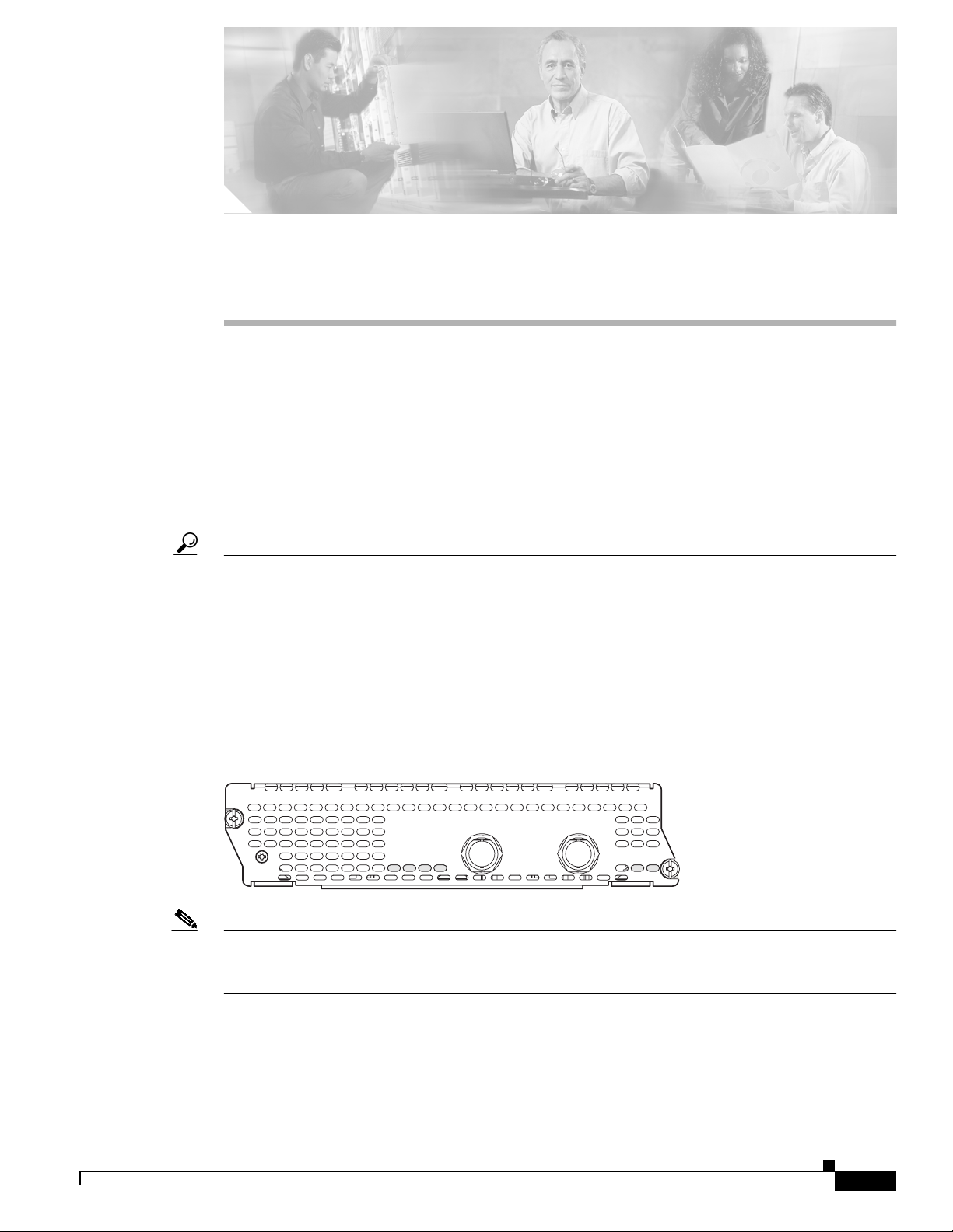
The NM-1T3/E3 network module is a single-port universal T3/E3 network module with integrated
CSU/DSU, clear channel, and subrate support. (See Figure 20-1.) Channels on the network module can
be configured as either T3 or E3 through Cisco IOS software.
Figure 20-1 1-Port T3/E3 Network Module Faceplate
NM-1T3/E3
Note The NM-1T3/E3 network module provides subrate T3 support for Digital Link, Kentrox, Larscom,
SEE MANUAL BEFORE INSTALLING NETWORK MODULE
TX
FERF/RAI
LP
CD
AIS
T3/E3
RX
AL
EN
72536
Verilink,and Adtran. The NM-1T3/E3 network module also provides subrate E3 support for Digital Link
and Kentrox.
OL-2485-20
Cisco Network Modules Hardware Installation Guide
20-1
Page 2
Chapter 20 Connecting T3/E3 Network Modules
Connecting T3/E3 Network Modules to the Network
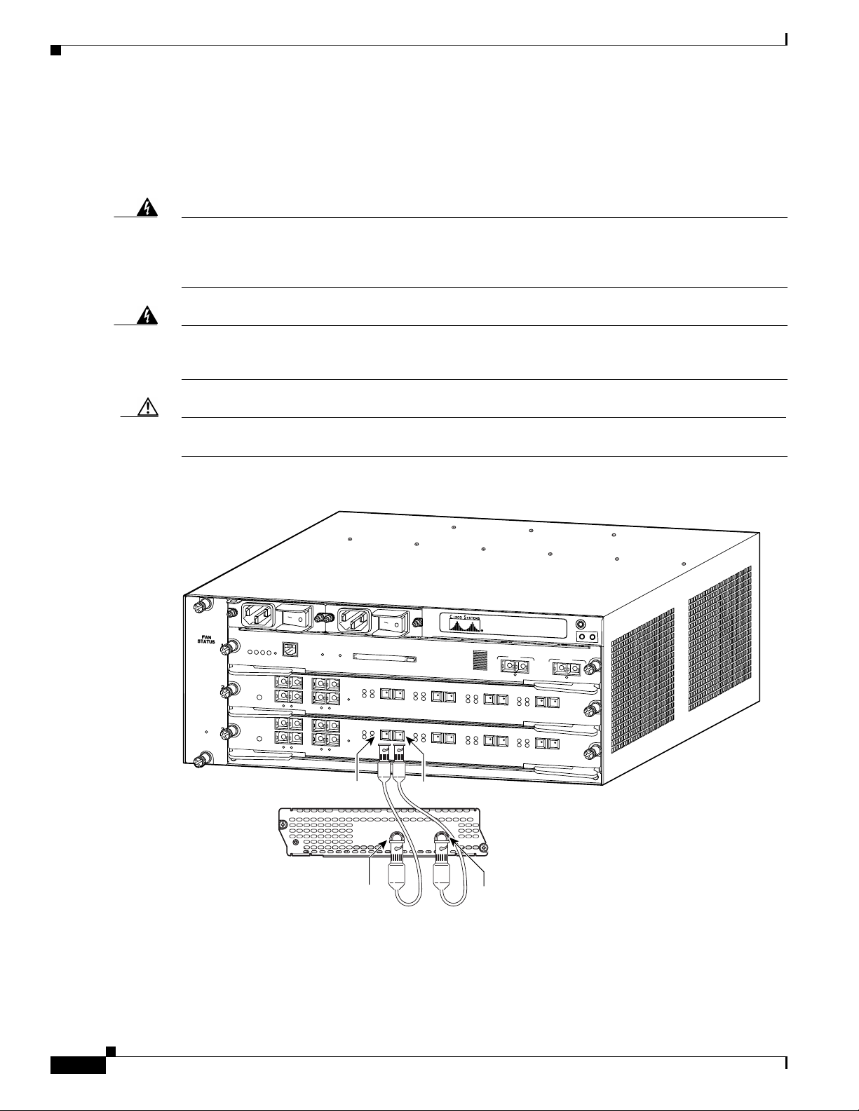
Connecting T3/E3 Network Modules to the Network
To connect a T3/E3 network module to the network, use a 75-ohm 728-A coaxial cable to connect the
BNC connector on the network module to a networking device. (See Figure 20-2.)
Warning
This equipment contains a ring signal generator (ringer), which is a source of hazardous voltage. Do
not touch the RJ-11 (phone) port wires (conductors), the conductors of a cable connected to the RJ-11
port, or theassociated circuit-board when the ringer is active. The ringeris activated by an incoming
call. Statement 1042
Warning
If the symbol of suitability with an overlaid cross appears above a port, you must not connect the port
to a public network that follows the European Union standards. Connecting the port to this type of
public network can cause severe injury or damage your router. Statement 1031
Caution To minimize transient surges, the internal wiring should not be routed in the same conduit with power
lines or external telephone lines.
Figure 20-2 Connecting a T3/E3 NetworkModule to a Networking Device (Cisco 7603 Router Shown)
WS-X6K-SUP2-2GE
SUPERVISOR2
OSM-4OC12 POS-SI
4 PORT OC-12 POS SM IR
OSM-4OC12 POS-SI
4 PORT OC-12 POS SM IR
STATUS
SYSTEM
CONSOLE
PWR MGMT
RESET
CONSOLE
PORT
MODE
CONSOLE
1
STATUS
STATUS
3
2
4
LINK
1
2
LINK
LINK
3
4
1
2
LINK
1
LINK
3
4
2
LINK
LINK
3
4
LINK
PCMCIA EJECT
RX
ACTIVE
TX
ACTIVE
TX
RX
RESET
CARRIER
ALARM
ACTIVE
TX
RX
RESET
CARRIER
ALARM
TX
RX
PORT 1
CARRIER
ALARM
RX
TX
ACTIVE
TX
RX
PORT 1
CARRIER
ALARM
Switch Load
100%
RX
TX
PORT 2
CARRIER
ALARM
RX
TX
PORT 2
CARRIER
ALARM
PORT 1
1%
ACTIVE
ACTIVE
LINK
RX
TX
TX
RX
PORT 3
CARRIER
ALARM
RX
TX
TX
RX
PORT 3
CARRIER
ALARM
PORT 2
LINK
RX
ACTIVE
TX
TX
RX
PORT4
RX
ACTIVE
TX
TX
RX
PORT4
72715
20-2
RX
NM-1T3/E3
SEE MANUAL BEFORE INSTALLING NETWORK MODULE
LP
CD
TX
Cisco Network Modules Hardware Installation Guide
TX
T3/E3
TX
FERF/RAI
AIS
RX
AL
EN
RX
OL-2485-20
Page 3

Chapter 20 Connecting T3/E3 Network Modules
Tip When connecting the T3/E3 network module to a port adapter used in another router series, verify that
you are connecting the TX port on the network module with the RX port on the port adapter, and the TX
port on the port adapter to the RX port on the network module.
T3/E3 Network Module LEDs
All network modules have an enable (EN) LED. This LED indicates that the module has passed its
self-tests and is available to the router. See Figure 20-3 and Table 20-1 for LEDs on the T3/E3 network
module.
Figure 20-3 T3/E3 LEDs
T3/E3 Network Module LEDs
NM-1T3/E3
SEE MANUAL BEFORE INSTALLING NETWORK MODULE
TX
FERF/RAI
LP
CD
AIS
CD
LED
LP
LED
FERF/RAI
LED
AIS
LED
T3/E3
RX
AL
EN
72537
AL
LED
EN
LED
Table 20-1 T3/E3 Network Module LEDs
LED Meaning
CD Green indicates that a signal is present on the port.
LP Yellow indicates that a loopback condition is present on the port.
AIS Yellow indicates an alarm on the DS3 transmission.
FERF/RAI Yellow indicates a remote failure at the far end of the connection.
AL Yellow indicates that the port is out of frame.
EN Green indicates that the network module has passed self-test and is available to
the router.
Related Documents
For additional information, see the following documents.
Tip For information on obtaining documentation, see the “Obtaining Documentation” section on page viii.
For information on obtaining technical assistance, see the “Obtaining Technical Assistance” section on
page xi.
OL-2485-20
Cisco Network Modules Hardware Installation Guide
20-3
Page 4

Related Documents
Cisco IOS Software Documentation
For information on Cisco IOS software features specific to the T3/E3 network module, see the Clear
Channel T3/E3 Network Module with Integrated CSU/DSU document.
Chapter 20 Connecting T3/E3 Network Modules
20-4
Cisco Network Modules Hardware Installation Guide
OL-2485-20
 Loading...