


Cisco Nexus 9516 NX-OS Mode Switch Hardware Installation Guide
First Published: 2014-06-24
Last Modified: 2019-03-05
Americas Headquarters
Cisco Systems, Inc.
170 West Tasman Drive
San Jose, CA 95134-1706
USA
http://www.cisco.com
Tel: 408 526-4000
800 553-NETS (6387)
Fax: 408 527-0883

THE SPECIFICATIONS AND INFORMATION REGARDING THE PRODUCTS IN THIS MANUAL ARE SUBJECT TO CHANGE WITHOUT NOTICE. ALL STATEMENTS,
INFORMATION, AND RECOMMENDATIONS IN THIS MANUAL ARE BELIEVED TO BE ACCURATE BUT ARE PRESENTED WITHOUT WARRANTY OF ANY KIND,
EXPRESS OR IMPLIED. USERS MUST TAKE FULL RESPONSIBILITY FOR THEIR APPLICATION OF ANY PRODUCTS.
THE SOFTWARE LICENSE AND LIMITED WARRANTY FOR THE ACCOMPANYING PRODUCT ARE SET FORTH IN THE INFORMATION PACKET THAT SHIPPED WITH
THE PRODUCT AND ARE INCORPORATED HEREIN BY THIS REFERENCE. IF YOU ARE UNABLE TO LOCATE THE SOFTWARE LICENSE OR LIMITED WARRANTY,
CONTACT YOUR CISCO REPRESENTATIVE FOR A COPY.
The following information is for FCC compliance of Class A devices: This equipment has been tested and found to comply with the limits for a Class A digital device, pursuant to part 15
of the FCC rules. These limits are designed to provide reasonable protection against harmful interference when the equipment is operated in a commercial environment. This equipment
generates, uses, and can radiate radio-frequency energy and, if not installed and used in accordance with the instruction manual, may cause harmful interference to radio communications.
Operation of this equipment in a residential area is likely to cause harmful interference, in which case users will be required to correct the interference at their own expense.
The following information is for FCC compliance of Class B devices: This equipment has been tested and found to comply with the limits for a Class B digital device, pursuant to part 15 of
the FCC rules. These limits are designed to provide reasonable protection against harmful interference in a residential installation. This equipment generates, uses and can radiate radio
frequency energy and, if not installed and used in accordance with the instructions, may cause harmful interference to radio communications. However, there is no guarantee that interference
will not occur in a particular installation. If the equipment causes interference to radio or television reception, which can be determined by turning the equipment off and on, users are
encouraged to try to correct the interference by using one or more of the following measures:
• Reorient or relocate the receiving antenna.
• Increase the separation between the equipment and receiver.
• Connect the equipment into an outlet on a circuit different from that to which the receiver is connected.
• Consult the dealer or an experienced radio/TV technician for help.
Modifications to this product not authorized by Cisco could void the FCC approval and negate your authority to operate the product
The Cisco implementation of TCP header compression is an adaptation of a program developed by the University of California, Berkeley (UCB) as part of UCB’s public domain version of
the UNIX operating system. All rights reserved. Copyright©1981, Regents of the University of California.
NOTWITHSTANDING ANY OTHER WARRANTY HEREIN, ALL DOCUMENT FILES AND SOFTWARE OF THESE SUPPLIERS ARE PROVIDED "AS IS" WITH ALL FAULTS.
CISCO AND THE ABOVE-NAMED SUPPLIERS DISCLAIM ALL WARRANTIES, EXPRESSED OR IMPLIED, INCLUDING, WITHOUT LIMITATION, THOSE OF
MERCHANTABILITY, FITNESS FOR A PARTICULAR PURPOSE AND NONINFRINGEMENT OR ARISING FROM A COURSE OF DEALING, USAGE, OR TRADE PRACTICE.
IN NO EVENT SHALL CISCO OR ITS SUPPLIERS BE LIABLE FOR ANY INDIRECT, SPECIAL, CONSEQUENTIAL, OR INCIDENTAL DAMAGES, INCLUDING, WITHOUT
LIMITATION, LOST PROFITS OR LOSS OR DAMAGE TO DATA ARISING OUT OF THE USE OR INABILITY TO USE THIS MANUAL, EVEN IF CISCO OR ITS SUPPLIERS
HAVE BEEN ADVISED OF THE POSSIBILITY OF SUCH DAMAGES.
Any Internet Protocol (IP) addresses and phone numbers used in this document are not intended to be actual addresses and phone numbers. Any examples, command display output, network
topology diagrams, and other figures included in the document are shown for illustrative purposes only. Any use of actual IP addresses or phone numbers in illustrative content is unintentional
and coincidental.
Cisco and the Cisco logo are trademarks or registered trademarks of Cisco and/or its affiliates in the U.S. and other countries. To view a list of Cisco trademarks, go to this URL: www.cisco.com
go trademarks. Third-party trademarks mentioned are the property of their respective owners. The use of the word partner does not imply a partnership relationship between Cisco and any
other company. (1721R)
©
2014–2018 Cisco Systems, Inc. All rights reserved.

CONTENTS
Trademarks ?
PREFACE
CHAPTER 1
CHAPTER 2
Preface vii
Audience vii
Documentation Conventions vii
Related Documentation for Cisco Nexus 9000 Series NX-OS Software viii
Documentation Feedback x
Obtaining Documentation and Submitting a Service Request x
Overview 1
Overview 1
Preparing the Site 7
Temperature Requirements 7
Humidity Requirements 7
Altitude Requirements 7
Dust and Particulate Requirements 8
Minimizing Electromagnetic and Radio Frequency Interference 8
CHAPTER 3
Shock and Vibration Requirements 9
Grounding Requirements 9
Planning for Power Requirements 9
Rack and Cabinet Requirements 13
Clearance Requirements 14
Installing a Chassis 17
Installing a Rack or Cabinet 17
Cisco Nexus 9516 NX-OS Mode Switch Hardware Installation Guide
iii

Contents
Inspecting the New Switch 18
Installing the Bottom-Support Rails 19
Installing a Chassis in a Rack or Cabinet 22
Grounding the Chassis 27
Starting Up the Switch 28
Connecting a 3-kW AC Power Supply to an AC Power Source 29
Connecting a 3-kW Universal AC/DC Power Supply to an AC Power Source 29
Connecting a 3-kW Universal AC/DC Power Supply to a DC Power Source 30
Connecting a 3-kW DC Power Supply to a DC Power Source 30
CHAPTER 4
CHAPTER 5
Connecting the Switch to the Network 35
Guidelines for Connecting Ports 35
Connecting a Console to the Switch 36
Connecting the Management Interface 37
Creating the Initial Switch Configuration 38
Connecting Interface Ports 40
Connecting a BASE-T Port to the Network 40
Disconnecting a BASE-T Port from the Network 40
Connecting an Optical Port to the Network 41
Disconnecting Optical Ports from the Network 41
Maintaining Transceivers and Optical Cables 42
Managing the Switch 43
Displaying Information About the Installed Hardware Modules 43
Displaying the Hardware Inventory for a Switch 43
Displaying the Backplane and Serial Number Information 44
Displaying Environmental Information for the Switch 44
Displaying the Current State of a Module 44
Displaying Temperatures for a Module 45
Connecting to a Module 47
Saving the Module Configuration 48
Shutting Down or Starting Up a Module 48
Purging a Nonfunctioning Module from the Running Configuration 49
Displaying Power Usage Information 49
Cisco Nexus 9516 NX-OS Mode Switch Hardware Installation Guide
iv

Reload a Module 50
Rebooting a Switch 50
Overview of Supervisor Modules 51
Overview of Power Modes 53
Power Mode Configuration Guidelines 54
Setting the Power Mode 57
Overview of Fan Trays 58
Displaying the Status for the Fan Trays 59
Contents
CHAPTER 6
Replacing or Installing Modules, Fan Trays, and Power Supplies 61
Preventing Electrostatic Damage 61
Installing or Replacing a Supervisor Module 61
Upgrading a Supervisor Module 64
Installing or Replacing a System Controller Module 65
Installing or Replacing a Line Card 67
Replacing a Fan Tray 70
Removing a Fan Tray 70
Installing a Fan Tray 72
Replacing a Fabric Module 73
Removing a Fabric Module 74
Installing a Fabric Module 78
Installing or Replacing Power Supplies 82
Installing or Replacing a 3-kW AC Power Supply 82
Installing or Replacing a 3-kW Universal AC/DC Power Supply 85
Installing or Replacing a 3.15-kW Dual Input Universal AC/DC Power Supply 88
APPENDIX A
Installing or Replacing a 3-kW DC Power Supply 89
Migrating the Switch from Using 40-Gigabit Line Cards to Using 100-Gigabit -EX/-FX Line Cards 93
System Specifications 95
Environmental Specifications 95
Switch Dimensions 95
Weights for the Chassis, Modules, Fan Trays, and Power Supplies 96
Power Specifications 98
Power Requirements for Switch Modules 98
Cisco Nexus 9516 NX-OS Mode Switch Hardware Installation Guide
v

Contents
Maximum Power Available to the Switch 98
Power Supply Specifications 98
3000-W AC Power Supply Specifications 99
3000-W Universal AC/DC Power Supply Specifications 99
3000-W Dual Input Universal AC/DC Power Supply Specifications 99
3000-W DC Power Supply Specifications 100
Power Cable Specifications 100
3-kW AC Power Cable Specifications 100
3-kW Universal AC/DC Power Cable Specifications 103
3-kW DC Power Supply Power Cord Specifications 103
APPENDIX B
APPENDIX C
LEDs 105
Chassis LEDs 105
System Controller LEDs 106
Supervisor Module LEDs 106
Fan Tray LEDs 107
Fabric Module LEDs 108
Line Card LEDs 108
Power Supply LEDs 109
Additional Kits 111
Accessory Kit 111
Cisco Nexus 9516 NX-OS Mode Switch Hardware Installation Guide
vi

Preface
• Audience, on page vii
• Documentation Conventions, on page vii
• Related Documentation for Cisco Nexus 9000 Series NX-OS Software, on page viii
• Documentation Feedback, on page x
• Obtaining Documentation and Submitting a Service Request, on page x
Audience
This publication is for hardware installers and network administrators who install, configure, and maintain
Cisco Nexus switches.
Documentation Conventions
Command descriptions use the following conventions:
bold
DescriptionConvention
Bold text indicates the commands and keywords that you enter literally
as shown.
Italic
[x | y]
{x | y}
[x {y | z}]
variable
Italic text indicates arguments for which the user supplies the values.
Square brackets enclose an optional element (keyword or argument).[x]
Square brackets enclosing keywords or arguments separated by a vertical
bar indicate an optional choice.
Braces enclosing keywords or arguments separated by a vertical bar
indicate a required choice.
Nested set of square brackets or braces indicate optional or required
choices within optional or required elements. Braces and a vertical bar
within square brackets indicate a required choice within an optional
element.
Indicates a variable for which you supply values, in context where italics
cannot be used.
Cisco Nexus 9516 NX-OS Mode Switch Hardware Installation Guide
vii
Related Documentation for Cisco Nexus 9000 Series NX-OS Software
Preface
DescriptionConvention
string
Examples use the following conventions:
italic screen font
!, #
A nonquoted set of characters. Do not use quotation marks around the
string or the string will include the quotation marks.
DescriptionConvention
Terminal sessions and information the switch displays are in screen font.screen font
Information you must enter is in boldface screen font.boldface screen font
Arguments for which you supply values are in italic screen font.
Nonprinting characters, such as passwords, are in angle brackets.< >
Default responses to system prompts are in square brackets.[ ]
An exclamation point (!) or a pound sign (#) at the beginning of a line
of code indicates a comment line.
Related Documentation for Cisco Nexus 9000 Series NX-OS
Software
The entire Cisco NX-OS 9000 Series documentation set is available at the following URL:
https://www.cisco.com/en/US/products/ps13386/tsd_products_support_series_home.html
Release Notes
The release notes are available at the following URL:
https://www.cisco.com/en/US/products/ps13386/prod_release_notes_list.html
Configuration Guides
These guides are available at the following URL:
https://www.cisco.com/en/US/products/ps13386/products_installation_and_configuration_guides_list.html
The documents in this category include:
• Cisco Nexus 2000 Series NX-OS Fabric Extender Software Configuration Guide for Cisco Nexus 9000
Series Switches
• Cisco Nexus 9000 Series NX-OS Fundamentals Configuration Guide
• Cisco Nexus 9000 Series NX-OS High Availability and Redundancy Guide
• Cisco Nexus 9000 Series NX-OS Interfaces Configuration Guide
• Cisco Nexus 9000 Series NX-OS Layer 2 Switching Configuration Guide
• Cisco Nexus 9000 Series NX-OS Multicast Routing Configuration Guide
viii
Cisco Nexus 9516 NX-OS Mode Switch Hardware Installation Guide

Preface
Preface
• Cisco Nexus 9000 Series NX-OS Quality of Service Configuration Guide
• Cisco Nexus 9000 Series NX-OS Security Configuration Guide
• Cisco Nexus 9000 Series NX-OS System Management Configuration Guide
• Cisco Nexus 9000 Series NX-OS Unicast Routing Configuration Guide
• Cisco Nexus 9000 Series NX-OS Verified Scalability Guide
• Cisco Nexus 9000 Series NX-OS VXLAN Configuration Guide
Other Software Documents
• Cisco Nexus 7000 Series and 9000 Series NX-OS MIB Quick Reference
• Cisco Nexus 9000 Series NX-OS Programmability Guide
• Cisco Nexus 9000 Series NX-OS Software Upgrade and Downgrade Guide
• Cisco Nexus 9000 Series NX-OS System Messages Reference
• Cisco Nexus 9000 Series NX-OS Troubleshooting Guide
• Cisco NX-OS Licensing Guide
• Cisco NX-OS XML Interface User Guide
Hardware Documents
• Cisco Nexus 3000 Series Hardware Installation Guide
• Cisco Nexus 92160YC-X NX-OS Mode Switch Hardware Installation Guide
• Cisco Nexus 92300YC NX-OS Mode Switch Hardware Installation Guide
• Cisco Nexus 92304QC NX-OS Mode Switch Hardware Installation Guide
• Cisco Nexus 9236C NX-OS Mode Switch Hardware Installation Guide
• Cisco Nexus 9272Q NX-OS Mode Switch Hardware Installation Guide
• Cisco Nexus 93108TC-EX NX-OS Mode Switch Hardware Installation Guide
• Cisco Nexus 93120TX NX-OS Mode Switch Hardware Installation Guide
• Cisco Nexus 93128TX NX-OS Mode Switch Hardware Installation Guide
• Cisco Nexus 93180LC-EX NX-OS Mode Switch Hardware Installation Guide
• Cisco Nexus 93180YC-EX NX-OS Mode Switch Hardware Installation Guide
• Cisco Nexus 9332PQ NX-OS-Mode Switch Hardware Installation Guide
• Cisco Nexus 9372PX and 9372PX-E NX-OS Mode Switches Hardware Installation Guide
• Cisco Nexus 9372TX and 9372TX-E NX-OS Mode Switches Hardware Installation Guide
• Cisco Nexus 9396PX NX-OS Mode Switch Hardware Installation Guide
• Cisco Nexus 9396TX NX-OS Mode Switch Hardware Installation Guide
Cisco Nexus 9516 NX-OS Mode Switch Hardware Installation Guide
ix

Preface
Documentation Feedback
• Cisco Nexus 9504 NX-OS Mode Switch Hardware Installation Guide
• Cisco Nexus 9508 NX-OS Mode Switch Hardware Installation Guide
• Cisco Nexus 9516 NX-OS Mode Switch Hardware Installation Guide
• Regulatory, Compliance, and Safety Information for the Cisco Nexus 3000 and 9000 Series
Documentation Feedback
To provide technical feedback on this document, or to report an error or omission, please send your comments
to nexus9k-docfeedback@cisco.com. We appreciate your feedback.
Obtaining Documentation and Submitting a Service Request
For information on obtaining documentation, using the Cisco Bug Search Tool (BST), submitting a service
request, and gathering additional information, see What's New in Cisco Product Documentation, at:
https://www.cisco.com/warp/public/687/Directory/DirTAC.shtml.
Subscribe to What's New in Cisco Product Documentation, which lists all new and revised Cisco technical
documentation as an RSS feed and delivers content directly to your desktop using a reader application. The
RSS feeds are a free service.
Cisco Nexus 9516 NX-OS Mode Switch Hardware Installation Guide
x

Overview
CHAPTER 1
Overview
• Overview, on page 1
This switch chassis includes the following modules:
• Supervisor modules (one or two)—one of the following types in slots SUP 1 and SUP 2 (Modules 27
and 28 in reports) (numbered from left to right on the chassis):
• System controllers (two) (N9K-SC-A) in slots SC 1 and SC 2 (Modules 29 and 30 in reports) (numbered
from left to right on the chassis)
• Line cards (up to 16) in slots LC 1 through LC 16 (Modules 1 and 16 in reports) (numbered from top to
bottom on the chassis) supported by the same type of fabric module
For compatibility information, please refer to the Line Card and Fabric Module Compatibility data sheets.
Note
Do not mix ACI-mode line cards with NX-OS mode line cards in the same switch.
• Fabric modules in slots FM 1 to FM 6 (Modules 21 and 26 in reports) (numbered from left to right on
the chassis)
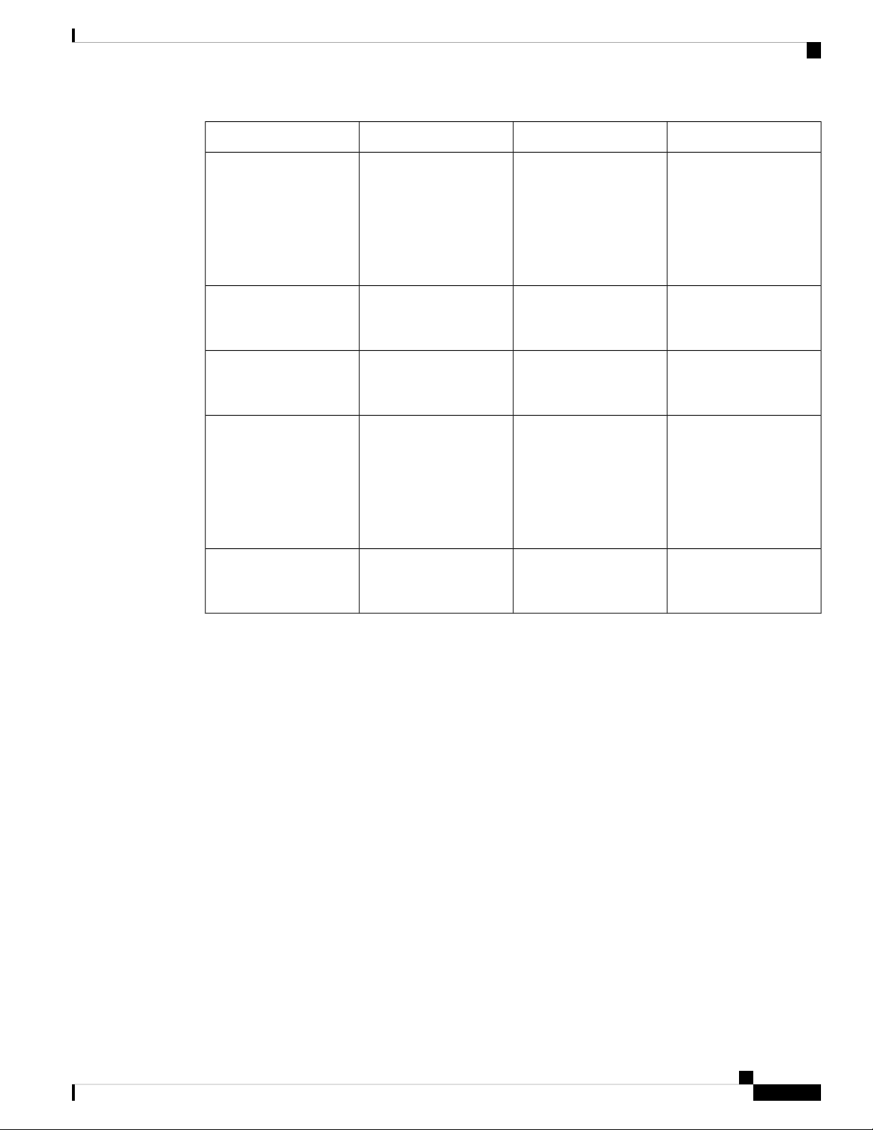
See the following table for the required fabric module types and quantities that are required for maximum
bandwidth.
Cisco Nexus 9516 NX-OS Mode Switch Hardware Installation Guide
1
Overview
Overview
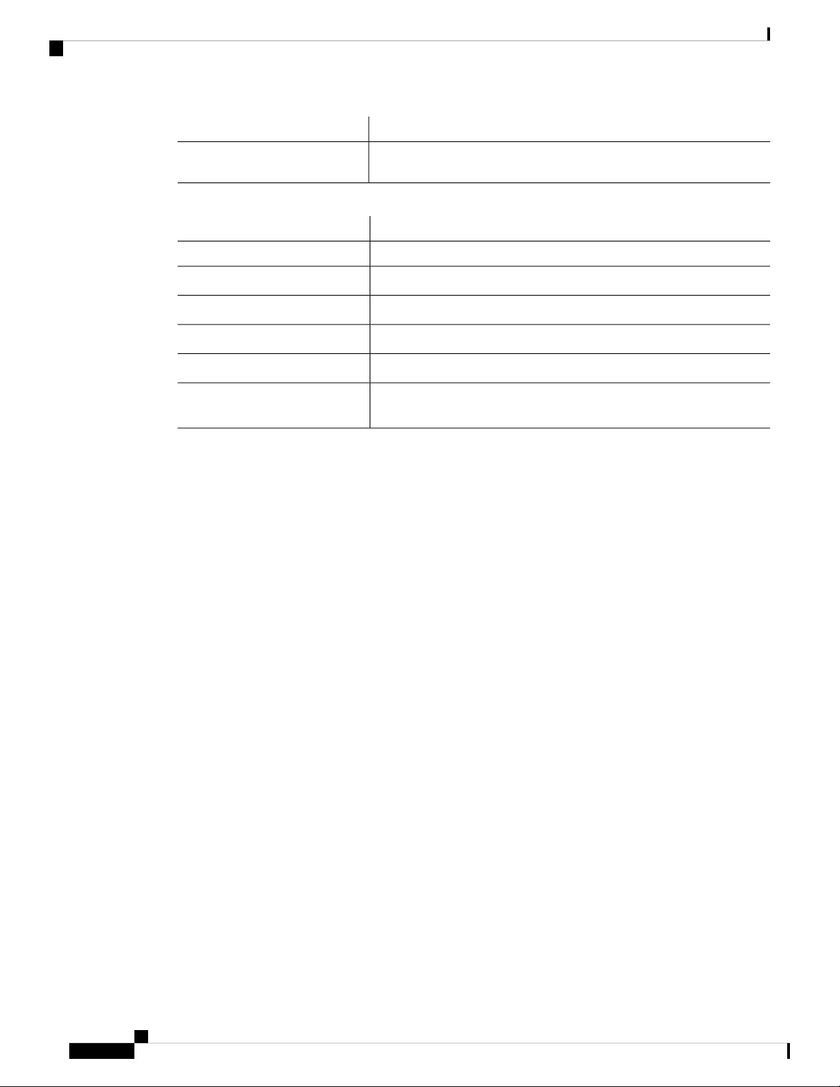
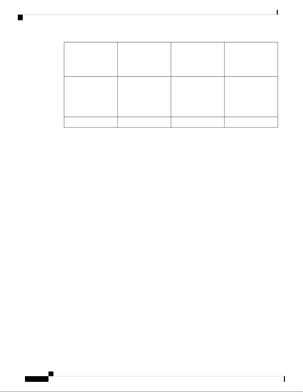
Table 1: Supported Fabric Modules and Line Cards
Fabric Module
N9K-C9516-FM-E
Required for
Maximum
Bandwidth
3N9K-C9516-FM
4
4
4
4
5
5
Supported Line CardsFabric Modules
N9K-X9536PQ
N9K-X9564PX
N9K-X9564TX
N9K-X9408PC-CFP2
N9K-X9432PQ
N9K-X9464PX
N9K-X9464TX
N9K-X9464TX2
N9K-X97160YC-EX
N9K-X9732C-EX
N9K-X9736C-EX
N9K-X9736C-FX
N9K-X9736Q-FX
N9K-C9516-FM-E2
4
4
4
4 (plus 1 for
redundancy)
4
5
5
4
N9K-X9788TC-FX
N9K-X97160YC-EX
N9K-X9732C-EX
N9K-X9732C-FX
N9K-X9736C-EX
N9K-X9736C-FX
N9K-X9736Q-FX
N9K-X9788TC-FX
Cisco Nexus 9516 NX-OS Mode Switch Hardware Installation Guide
2
Overview
Note
The fabric modules must be installed in specific slots as follows (installing fabric
modules in other slots can cause a module mismatch condition):
• For three modules, they must be in slots FM 2, FM 4, and FM 6
• For four modules, they must be in slots FM2, FM 3, FM 4, and FM 6
• For five modules, they can be in slots FM 1, FM 2, FM 3, FM 4, and FM 6.
Alternatively, they can be in Slots FM 2, FM 3, FM 4, FM 5, and FM 6.
• For five FM-E or FM-E2 modules, they must be in Slots FM 2, FM 3, FM
4, FM 5, and FM 6
• For six modules, they are in slots FM 1, FM 2, FM 3, FM 4, FM 5, and FM
6
Overview
Note
All of the fabric modules in a modular switch must be of the same type.
Note
Fabric slots FM 2, FM 4, or FM 6 must be filled with functioning fabric modules
or blank modules with power connectors (N9K-C9516-FM-Z) in order to provide
power to the fan trays covering those modules.
If fabric slots FM 1, FM 3, or FM 5 are not filled with a fabric module, you must
make sure that they have a blank module (N9K-C9516-FM-CV) installed to
preserve the designed airflow.
Note
For more information about Line card and fabric module compatibility, see the
Cisco Nexus 9500 Platform Line Cards and Fabric Modules Data Sheet.
• Fan trays (three) (N9K-C9516-FAN) in slots FAN 1 to FAN 3 (Modules 41 to 43 in reports) (numbered
from left to right on the chassis)
• Power supplies (up to five with the combined power mode, up to six with the n+1 power redundancy
mode, or up to ten with the n+n power redundancy mode) in slots PS 1 to PS 10 (Modules 31 to 40 in
reports) (numbered from left to right on the chassis)
• Cisco Nexus 9500 Series 3-kW AC power supply (N9K-PAC-3000W-B)
• Cisco Nexus 9500 Series 3-kW Universal AC/DC power supply (N9K-PUV-3000W-B)
• Cisco Nexus 9500 Series 3.15-kW Dual Input Universal AC/DC power supply
(N9K-PUV2-3000W-B)
• Cisco Nexus 9500 Series 3-kW (-48 V) DC power supply (N9K-PDC-3000W-B)
Cisco Nexus 9516 NX-OS Mode Switch Hardware Installation Guide
3

Overview
Note
The switch can be powered by a mix of AC, DC, HVAC/HVDC power sources.
Note
All chassis slots are numbered from left to right or from top to bottom.
The following figure shows the hardware features seen from the front of the chassis.
Overview
1
42 vertical mounting
brackets used to mount
the chassis onto a rack
3-kW AC, Universal
AC/DC, or DC power
supplies (AC power
supplies shown)
Cisco Nexus 9516 NX-OS Mode Switch Hardware Installation Guide
4
Overview
Overview
Chassis LEDs5I/O modules (up to 16)2
3
6Supervisor modules (1 or
2)
Chassis handles (used
only for positioning the
chassis on the bottom
support rails—do not use
these handles for lifting
the chassis)
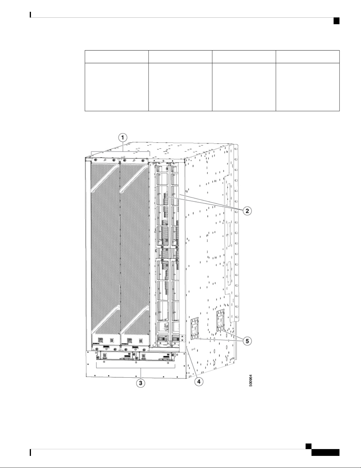
The following figure shows the hardware features seen from the rear of the chassis (one fan tray has been
removed to show the fabric modules behind the fan trays).
Cisco Nexus 9516 NX-OS Mode Switch Hardware Installation Guide
5
Overview
Overview
1
Grounding pad4Fan trays (3—right fan
tray not shown in order to
display the fabric modules
located behind the fan
trays)
2
5Fabric modules (up to 6
with up to 2 behind each
fan tray)
Chassis handles (used
only for positioning the
chassis on the bottom
support rails—do not use
these handles for lifting
the chassis)
System controllers (2)3
Cisco Nexus 9516 NX-OS Mode Switch Hardware Installation Guide
6

Preparing the Site
• Temperature Requirements, on page 7
• Humidity Requirements, on page 7
• Altitude Requirements, on page 7
• Dust and Particulate Requirements, on page 8
• Minimizing Electromagnetic and Radio Frequency Interference, on page 8
• Shock and Vibration Requirements, on page 9
• Grounding Requirements, on page 9
• Planning for Power Requirements, on page 9
• Rack and Cabinet Requirements, on page 13
• Clearance Requirements, on page 14
Temperature Requirements
The switch requires an operating temperature of 32 to 104 degrees Fahrenheit (0 to 40 degrees Celsius). If
the switch is not operating, the temperature must be between –40 to 158 degrees Fahrenheit (–40 to 70 degrees
Celsius).
CHAPTER 2
Humidity Requirements
Buildings in which the climate is controlled by air-conditioning in the warmer months and by heat during the
colder months usually maintain an acceptable level of humidity for the switch equipment. However, if the
switch is located in an unusually humid location, use a dehumidifier to maintain the humidity within an
acceptable range.
Altitude Requirements
This switch is rated to operate at altitudes from 0 to 10,000 feet (0 to 3,048 meters). If you operate this switch
at a higher altitude (low pressure), the efficiency of forced and convection cooling is reduced and can result
in electrical problems that are related to arcing and corona effects. This condition can also cause sealed
components with internal pressure, such as electrolytic capacitors, to fail or to perform at a reduced efficiency.
Cisco Nexus 9516 NX-OS Mode Switch Hardware Installation Guide
7

Preparing the Site
Dust and Particulate Requirements
Dust and Particulate Requirements
Exhaust fans cool power supplies and system fans cool switches by drawing in air and exhausting air out
through various openings in the chassis. However, fans also ingest dust and other particles, causing contaminant
buildup in the switch and increased internal chassis temperature. Dust and particles can act as insulators and
interfere with the mechanical components in the switch. A clean operating environment can greatly reduce
the negative effects of dust and other particles.
In addition to regular cleaning, follow these precautions to avoid contamination of your switch:
• Do not permit smoking near the switch.
• Do not permit food or drink near the switch.
Minimizing Electromagnetic and Radio Frequency Interference
Electromagnetic interference (EMI) and radio frequency interference (RFI) from the switch can adversely
affect other devices, such as radio and television (TV) receivers. Radio frequencies that emanate from the
switch can also interfere with cordless and low-power telephones. Conversely, RFI from high-power telephones
can cause spurious characters to appear on the switch monitor.
RFI is defined as any EMI with a frequency above 10 kHz. This type of interference can travel from the switch
to other devices through the power cable and power source or through the air as transmitted radio waves. The
Federal Communications Commission (FCC) publishes specific regulations to limit the amount of EMI and
RFI that are emitted by computing equipment. Each switch meets these FCC regulations.
To reduce the possibility of EMI and RFI, follow these guidelines:
• Cover all open expansion slots with a blank filler plate.
• Always use shielded cables with metal connector shells for attaching peripherals to the switch.
When wires are run for any significant distance in an electromagnetic field, interference can occur to the
signals on the wires with the following implications:
• Bad wiring can result in radio interference emanating from the plant wiring.
• Strong EMI, especially when it is caused by lightning or radio transmitters, can destroy the signal drivers
and receivers in the chassis and even create an electrical hazard by conducting power surges through
lines into equipment.
Note
To predict and prevent strong EMI, you need to consult experts in radio frequency interference (RFI).
The wiring is unlikely to emit radio interference if you use a twisted-pair cable with a good distribution of
grounding conductors. If you exceed the recommended distances, use a high-quality twisted-pair cable with
one ground conductor for each data signal when applicable.
Cisco Nexus 9516 NX-OS Mode Switch Hardware Installation Guide
8

Preparing the Site
Shock and Vibration Requirements
Caution
If the wires exceed the recommended distances, or if wires pass between buildings, give special consideration
to the effect of a lightning strike in your vicinity. The electromagnetic pulse that is caused by lightning or
other high-energy phenomena can easily couple enough energy into unshielded conductors to destroy electronic
switches. You will want to consult experts in electrical surge suppression and shielding if you had similar
problems in the past.
Shock and Vibration Requirements
The switch has been shock- and vibration-tested for operating ranges, handling, and earthquake standards.
Grounding Requirements
The switch is sensitive to variations in voltage that is supplied by the power sources. Overvoltage, undervoltage,
and transients (or spikes) can erase data from memory or cause components to fail. To protect against these
types of problems, ensure that there is an earth-ground connection for the switch. You can connect the grounding
pad on the switch either directly to the earth-ground connection or to a fully bonded and grounded rack.
When you properly install the chassis in a grounded rack, the switch is grounded because it has a metal-to-metal
connection to the rack. Alternatively, you can ground the chassis by using a customer-supplied grounding
cable that meets your local and national installation requirements. For U.S. installations, we recommend
6-AWG wire. Connect your grounding cable to the chassis with a grounding lug (provided in the switch
accessory kit) and to the facility ground.
Note
You automatically ground AC power supplies when you connect them to AC power sources. For DC power
supplies, you must connect a grounding wire when wiring the power supply to the DC power source.
Planning for Power Requirements
To plan for the power requirements of a switch, you must determine each of the following:
• Power requirements for all the switch components
• Minimum number of power supplies required to power the components that are installed in the switch.
• Power mode to use and the number of extra power supplies required for that mode.
Ensure that the circuit that is used for the switch is dedicated to the switch to minimize the possibility of circuit
failure. Also, ensure that the switch uses either AC or DC power sources, not a mix of AC and DC power
sources.
Calculate the power that is required for operations (available power) and redundancy (reserve power), then
you can plan for the required number of input power receptacles. The power receptacles will be within reach
of the switch location.
Cisco Nexus 9516 NX-OS Mode Switch Hardware Installation Guide
9
Preparing the Site
Planning for Power Requirements
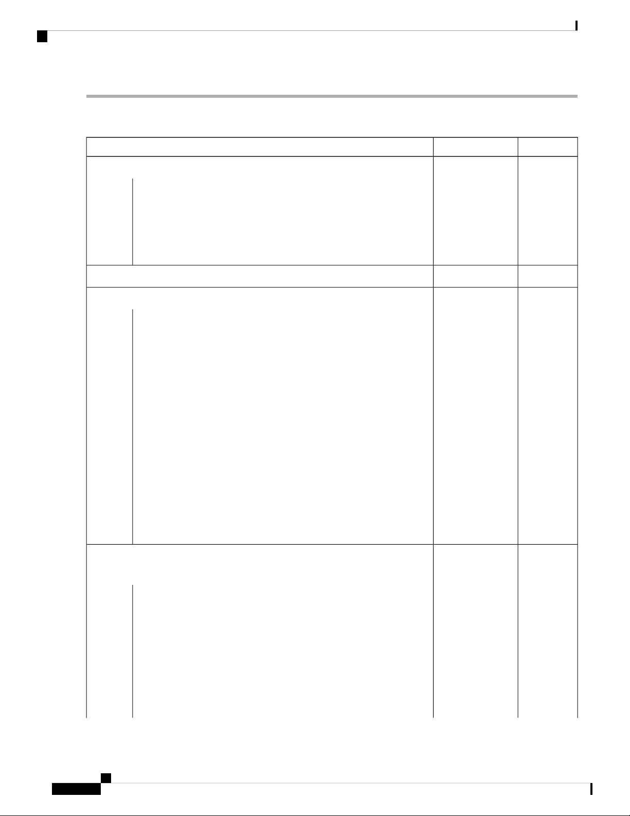
Step 1 Determine the power requirement for the modules in the switch by summing the maximum wattage for each installed
module, see the following table.
MaximumTypicalComponent
——Supervisor Modules
80 W69 WSupervisor A (N9K-SUP-A)–
80 W69 WSupervisor A+ (N9K-SUP-A+)–
90 W75 WSupervisor B (N9K-SUP-B)–
80 W75 WSupervisor B+ (N9K-SUP-B+)–
25 W14 WSystem Controller (N9K-SC-A)
504 W330 WLine cards that are supported by N9K-C9516-FM fabric modules
432 W310 W8-port 100-Gigabit Ethernet CFP2 line card (N9K-X9408PC-CFP2)–
–
QSFP+ line card (N9K-X9464PX)
–
(N9K-X9464TX)
–
(N9K-X9464TX2)
–
(N9K-X9564PX)
–
(N9K-X9564TX)
Line Cards supported by 100-Gigabit -E and
-E2 fabric modules
–
QSFP28 line card (N9K-X97160YC-EX)
–
card (N9K-X9788TC-FX)
980 W
439 W
300 W240 W32-port 40-Gigabit Ethernet QSFP+ line card (N9K-X9432PQ)–
400 W360 W36-port 40-Gigabit Ethernet QSFP+ line card (N9K-X9536PQ)–
240 W160W48-port 1/10-Gigabit Ethernet SFP+ and 4-port 40-Gigabit Ethernet
360 W300 W48-port 1/10GBASE-T and 4-port 40-Gigabit Ethernet QSFP+ line card
360 W288 W48-port 1/10GBASE-T and 4-port 40-Gigabit Ethernet QSFP+ line card
400 W300 W48-port 1/10-Gigabit Ethernet SFP+ plus 4-port QSFP+ line card
540 W450 W48-port 1/10GBASE-T and 4-port 40-Gigabit Ethernet QSFP+ line card
1320 W
900 W
516 W415 W48-port 10/25-Gigabit Ethernet SFP28 and 4-port 40/100-Gigabit Ethernet
684 W346 W48-port 10-Gigabit Ethernet SFP+ and 4-port 100-Gigabit Ethernet line
792 W632 W36-port 100-Gigabit Ethernet QSFP28 line card (N9K-X9736C-EX)–
720 W607 W36-port 100-Gigabit Ethernet QSFP28 line card (N9K-X9736C-FX)–
684 W571 W36-port 40-Gigabit Ethernet QSFP28 line card (N9K-X9736Q-FX)–
Cisco Nexus 9516 NX-OS Mode Switch Hardware Installation Guide
10

Preparing the Site
Planning for Power Requirements
MaximumTypicalComponent
720 W430 W32-port 100-Gigabit Ethernet QSFP28 line card (N9K-X9732C-EX)–
840 W32-port 100-Gigabit Ethernet QSFP28 line card (N9K-X9732C-FX)–
600 W330 WFan Trays (N9K-C9516-FAN)
For example, to determine the maximum amount of power that your fully loaded switch consumes, add the maximum
power consumption of two supervisor A modules (2 x 80 W = 160 W), two system controllers (2 x 25 W = 50 W), 16
48-port 10GBASE-T line cards (16 x 540 W = 8640 W), six fabric modules (6 x 504 W = 3024 W), and three fan trays
(3 x 451 W = 1353 W). The total is 13,227 W.
Step 2 Determine the number of power supplies required to power the modules that are installed in the switch by dividing the
module power requirement amount (see Step 1) by the output wattage (3000 W) of the power supplies installed in the
switch. Round up the fractional result to the nearest ones digit.
For example, if you are installing a switch with maximum consumption of 13,224 W, you need five power supplies
(13,224 W / 3000 W = 4.41 [rounded up to three power supplies]) to operate the switch and its modules.
Step 3 Determine the amount of power that is required from a power source.
The power supplies are rated to have at least 91-percent efficiency.
• To determine the input power (Watts) from the power source to the power supplies, divide the output power of each
power supply (3000 W) by the efficiency of the power supply (0.91) and then multiply the result by the number of
power supplies required to power the switch. For example, if the switch uses 5 power supplies, you can calculate
the amount of power that is required from the power source as follows:
3000 W output / 0.91 efficiency X 5 power supplies = 16,485 W
• To determine the number of Amps (A) that are required to power the switch, divide the maximum Watts that is
required for by the voltage that is used as shown in the following examples:
• For 16,485 A at 200-volts AC (VAC), use the following formula:
(16,485 W)/(200 VAC) = 82.5 A
• For 16,485 A at 277-volts AC (VAC), use the following formula:
(16,485 W)/(277 VAC) = 59.5 A
• For 16,48516,500 A at 380-volts DC (VDC), use the following formula:
(16,485 W)/(380 VDC) = 43.4 A
• To determine the required BTUs, multiply the Watts that is required for the power source by 3.41214163.
For example, for 16,485 W, use the following formula:
(16,485 W) X (3.41214163 BTU) = 56,249
To size the circuit breaker for the required amperage, you must also divide the required amperage by the percentage. For
example, if the switch requires an input amperage of 82.5 A and you are able to use up to 80 percent of the capacity of
a circuit breaker, you use the following formula to calculate the minimum amperage that is required of the circuit breaker:
(82.5 A)/ (80% or 0.80) = 103.1 amps
Cisco Nexus 9516 NX-OS Mode Switch Hardware Installation Guide
11
Preparing the Site
Planning for Power Requirements
Step 4 Select one of the following power modes to determine the number of additional power supplies required for reserve
power:
• Combined power—Do not add any power supplies to the number of power supplies that are calculated for the
available power in Step 2. This power mode does not provide power redundancy, so no extra power supplies are
needed.
• n+1 redundancy—Add one power supply (reserve power supply) that can output as much power as the most powerful
power supply that is used for active power. This form of power redundancy provides a reserve power supply that
can replace any active power supply that goes offline.
• n+n redundancy—Add enough power supplies (reserve power supplies) to at least equal the total output of the active
power supplies (the number of power supplies that are calculated in Step 2). Typically, you double the number of
power supplies. Plan for a second power source for the reserve power supplies. For example, if you calculate that
you need two 3-kW power supplies for 6 kW of available power, you need another two 3-kW power supplies for 6
kW of reserve power (for a total of four 3-kW power supplies used for available and reserve power).
Step 5 Be sure that the power source circuits are dedicated to the switch and not to other electrical equipment.
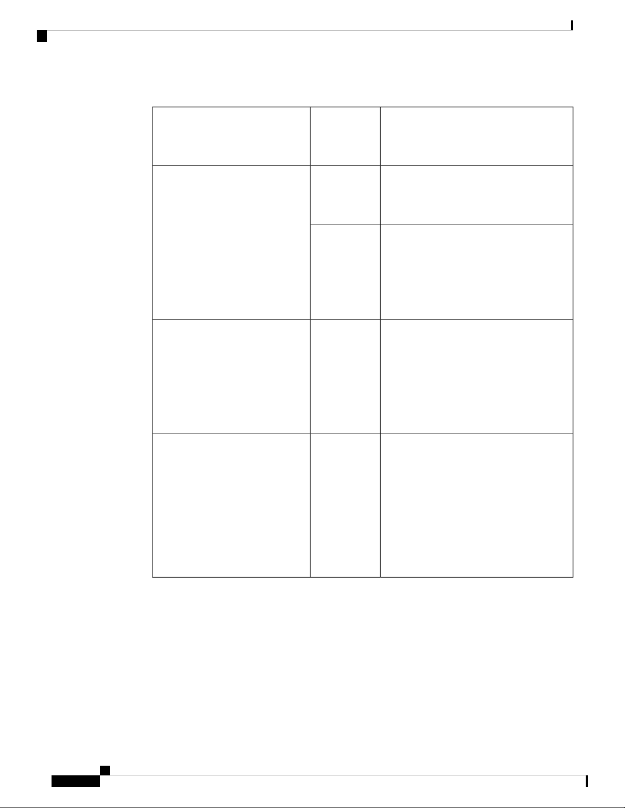
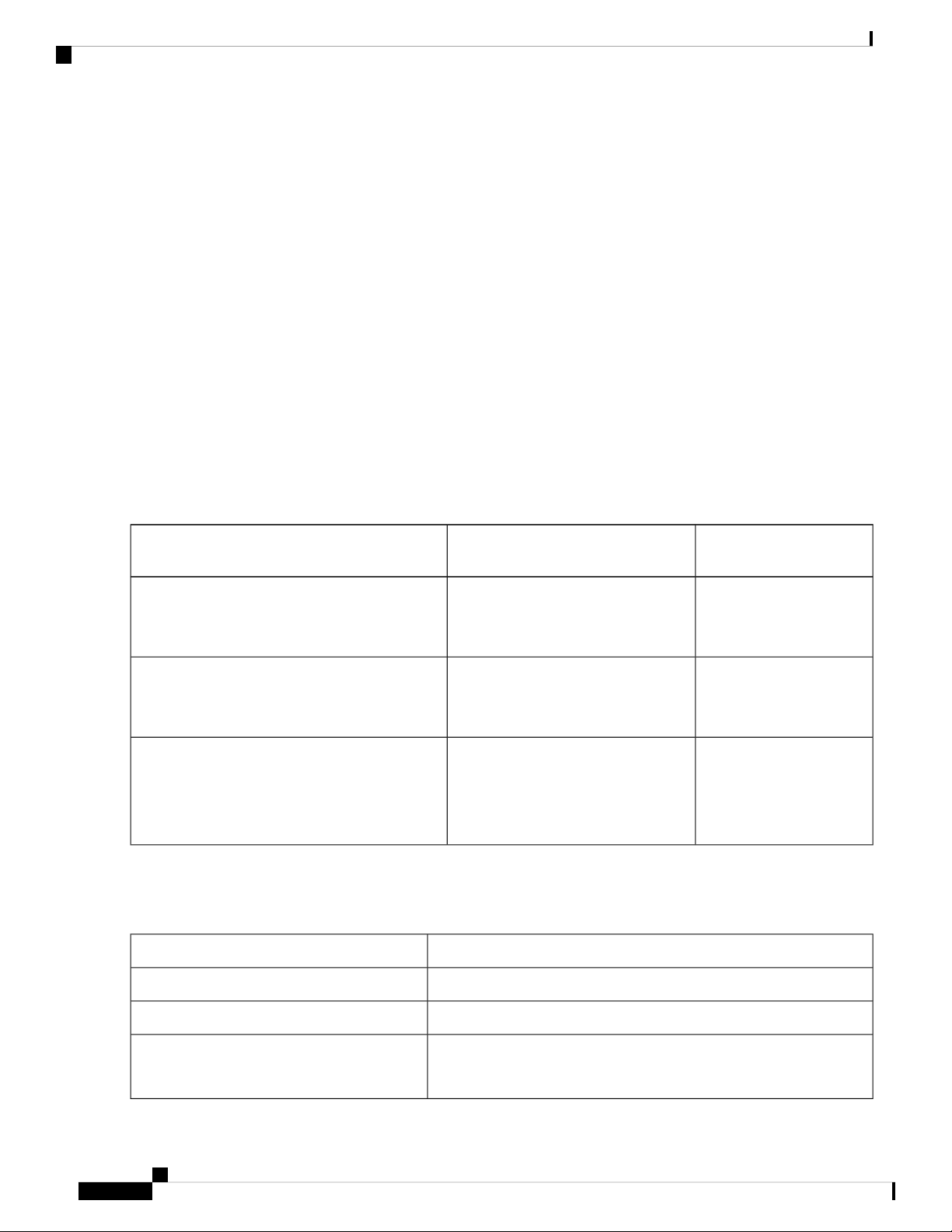
For combined mode or n+1 redundancy mode, you need only one dedicated circuit. For n+n redundancy, you must have
two dedicated power circuits, with each circuit powering half of the 3-kW power supplies. The requirements for each
circuit are listed in the following table.
Number of CircuitsPower Supply
Requirement for Each
Circuit
3-kW AC power supply (N9K-PAC-3000W-B)
1 (combined mode or n+1 redundancy
16 A at 200 to 240 VAC
mode)
2 (n+n redundancy mode)
3-kW Universal AC/DC power supply
(N9K-PUV-3000W-B and N9K-PUV2-3000W-B)
1 (combined mode or n+1 redundancy
mode)
AC power: 200 to 277 VAC
DC power: 240 to 380 VDC
2 (n+n redundancy mode)
3-kW DC power supply (N9K-PDC-3000W-B)
1 (combined mode or n+1 redundancy
mode)
2 (n+n redundancy mode)
45A at -40 to -75 VDC
(-48 VDC nominal US)
(-60 VDC nominal
international)
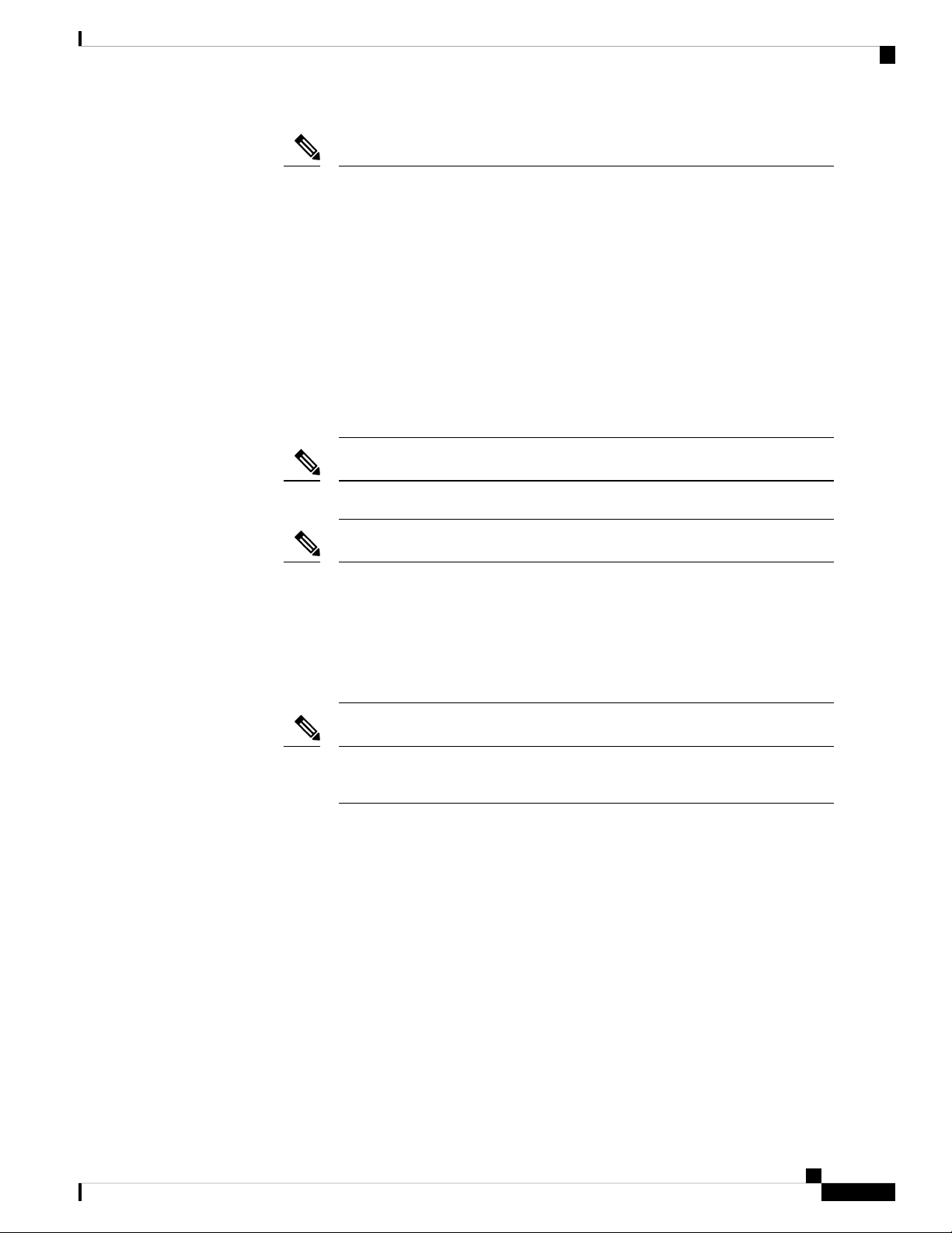
Step 6 Plan the placement of the input power receptacles within reach of the power cables that are used for each power supply,
see the following table for the maximum distances.
Typically, power receptacles are placed on the rack with the switch.
Maximum Distance Between Receptacle and Power SupplyPower Supply
8 to 12 feet (2.5 to 3.5 m)3-kW AC power supplies
3-kW DC power supplies
Cisco Nexus 9516 NX-OS Mode Switch Hardware Installation Guide
12
14 feet (4.27 m)3-kW Universal AC/DC power supplies
You provide four 6-gauge wires (recommended) and cuts that wire to
the required length. We provide four 6-gauge lugs to connect those
wires to the DC power supply.

Preparing the Site
Rack and Cabinet Requirements
Note
The switch can be powered by a mix of AC, DC, HVAC/HVDC power sources.
Rack and Cabinet Requirements
You can install the following types of racks or cabinets for your switch:
• Standard perforated cabinets
• Solid-walled cabinets with a roof fan tray (bottom-to-top cooling)
• Standard open four-post Telco racks
To install the switch in a cabinet that is located in a hot-aisle and cold-aisle environment, fit the cabinet with
baffles to prevent exhaust air from recirculating into the chassis air intake.
Work with your cabinet vendors to determine which of their cabinets meet the following requirements or see
the Cisco Technical Assistance Center (TAC) for recommendations:
• Use a standard 19-inch (48.3-cm), four-post Electronic Industries Alliance (EIA) cabinet or rack with
mounting rails that conform to English universal hole spacing per section 1 of the ANSI/EIA-310-D-1992
standard.
• The height of the rack or cabinet must accommodate the 21-RU (36.7 inches or 93.4 cm) height of the
switch and its bottom support bracket.
• The depth of a four-post rack must be 24 to 32 inches (61.0 to 81.3 cm) between the front and rear
mounting rails (for proper mounting of the bottom-support brackets or other mounting hardware).
• Required clearances between the chassis and the edges of its rack or the interior of its cabinet are as
follows:
• 4.5 inches (11.4 cm) between the front of the chassis and the front of the rack or interior of the
cabinet (required for cabling and module handles).
• 3.0 inches (7.6 cm) between the rear of the chassis and the interior of the cabinet (required for airflow
in the cabinet if used).
• No clearance is required between the chassis and the sides of the rack or cabinet (no side airflow).
Also, you must consider the following site requirements for the rack:
• Power receptacles must be located within reach of the power cords that are used with the switch.
• Power cords for the 3-kW AC power supplies are 8 to 12 feet (2.5 to 4.3 m) long.
• Power cords for the 3-kW Universal AC power supplies are 14 feet (4.27 m) long.
Note
The power cables for the 3-kW DC power supply are provided by and sized you.
Cisco Nexus 9516 NX-OS Mode Switch Hardware Installation Guide
13
Clearance Requirements
Preparing the Site
• Clearance is required for cables that connect to as many as 768 ports (in addition to the cabling required
for other devices in the same rack). These cables must not block access to any removable chassis modules
or block airflow into or out of the chassis. Route the cables through the cable management frames on the
left and right sides of the chassis.
Also, you must have power receptacles that are located within reach of the power cords that are used with the
switch.
Warning
Statement 1048—Rack Stabilization
Stability hazard. The rack stabilizing mechanism must be in place, or the rack must be bolted to the floor
before you slide the unit out for servicing. Failure to stabilize the rack can cause the rack to tip over.
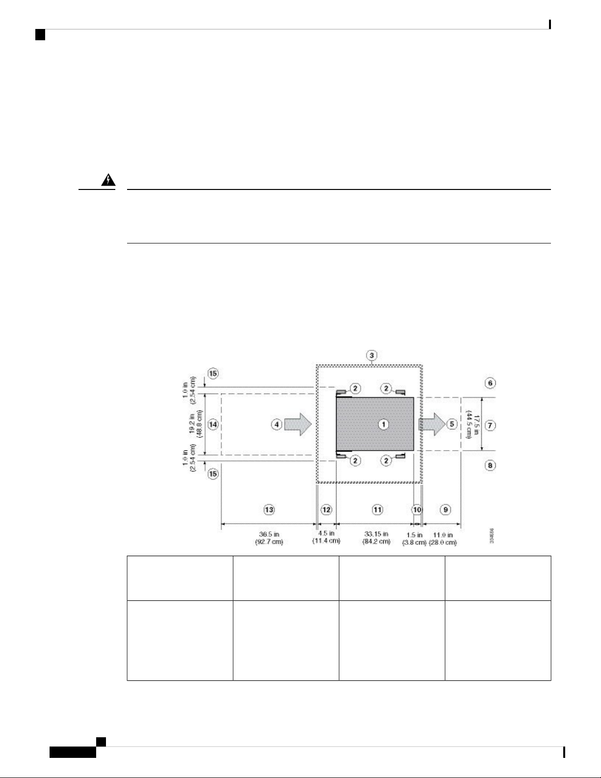
Clearance Requirements
Provide the chassis with adequate clearance between the chassis and any other rack, device, or structure so
that you can properly install the chassis. Provide the chassis with adequate clearance to route cables, provide
airflow, and maintain the switch. For the clearances required for an installation of this chassis, see the following
figure.
9Chassis1
2
and rails
Cisco Nexus 9516 NX-OS Mode Switch Hardware Installation Guide
14
10Vertical rack-mount posts
Rear service clearance
required to replace fan
trays and fabric modules.
Minimum clearance
required for module
handles (up to 6 inches
[15.24 cm] recommended
for optimal airflow) when
using cabinet doors
Preparing the Site
Clearance Requirements
Chassis depth11Cabinet (optional)3
4
12Air intake from the cold
aisle for all modules and
power supplies
Recommended clearance
for cable management and
ejector handles on line
cards (6 inches [15.24 cm]
recommended for optimal
airflow) when using
cabinet doors
5
13Air exhaust to the hot
aisle for all modules and
power supplies
6
14No left-side clearance
required (no airflow on
the left side).
15Chassis width7
Clearance required for
installing the chassis and
replacing line cards
Width of the chassis plus
vertical mounting brackets
on each side
Side clearance, that is
required for older line
card handle rotation (not
required for the current
line cards which have
handles that rotate
differently).
8
No right-side clearance
required (no airflow on
the right side).
Cisco Nexus 9516 NX-OS Mode Switch Hardware Installation Guide
15

Clearance Requirements
Preparing the Site
Cisco Nexus 9516 NX-OS Mode Switch Hardware Installation Guide
16

Installing a Chassis
• Installing a Rack or Cabinet, on page 17
• Inspecting the New Switch, on page 18
• Installing the Bottom-Support Rails, on page 19
• Installing a Chassis in a Rack or Cabinet, on page 22
• Grounding the Chassis, on page 27
• Starting Up the Switch, on page 28
Installing a Rack or Cabinet
Before you install the switch, you must install a standard four-post, 19-inch (48.3-cm) EIA data center rack
(or a cabinet that contains such a rack) that meets the requirements that are listed in Rack and Cabinet
Requirements, on page 13.
CHAPTER 3
Warning
Warning
Step 1 Bolt the rack to the subfloor before moving the chassis onto it.
Step 2 If the rack has bonded construction, connect it to the earth ground. This action enables you to ground the switch and its
components and to ground your electrostatic discharge (ESD) wrist strap. This action prevents discharge damage when
you handle ungrounded components during installation.
Step 3 If you need access to the source power at the rack, include one of the following:
• For AC power, include an AC circuit that meets the power specifications of the switch, see Power Requirements for
Statement 1048—Rack Stabilization
Stability hazard. The rack stabilizing mechanism must be in place, or the rack must be bolted to the floor
before you slide the unit out for servicing. Failure to stabilize the rack can cause the rack to tip over.
Statement 1018—Supply Circuit
Take care when connecting units to the supply circuit so that wiring is not overloaded.
Switch Modules, on page 98. This circuit must include receptacles that match your local and national requirements
and match the needs of the power cable that is used with the power supply unit.
Cisco Nexus 9516 NX-OS Mode Switch Hardware Installation Guide
17
Inspecting the New Switch
• For DC power, include a DC circuit that meets the power specifications of the switch see Power Requirements for
Switch Modules, on page 98). This circuit must include a circuit breaker so that you can safely connect the power
cables to the power supply.
Inspecting the New Switch
Before you install a new chassis, unpack and inspect it to be sure that you have all the items that you ordered.
Verify that the switch was not damaged during shipment.
Installing a Chassis
Caution
Step 1 Compare the shipment to the equipment list that is provided by your customer service representative and verify that you
have received your ordered items. The shipment includes boxes for the following:
• System chassis, which includes the following installed components:
When you handle the chassis or its components, you must follow ESD protocol to prevent ESD damage. This
protocol includes but is not limited to wearing an ESD wrist strap that you connect to the earth ground.
Tip
Do not discard the shipping container when you unpack the switch. Flatten the shipping cartons and store
them with the pallet that was used for the system. If you move or ship the system in the future, you will need
these containers.
• Supervisor modules (1 or 2) of the following types (must be the same type):
• Supervisor A (N9K-SUP-A)
• Supervisor A+ (N9K-SUP-A+)
• Supervisor B (N9K-SUP-B) (required for -R line cards)
• Supervisor B+ (N9K-SUP-B+) (required for -R line cards)
• System controllers (2) (N9K-SC-A)
• Line cards (1 to 16 line cards) as described in the Overview in Chapter 1.
• Fabric modules—See the Overview in Chapter 1 for quantity and type. The switch must have only one type of
fabric module that supports the installed line cards.
The fabric modules must be installed in specific slots as follows (installing fabric modules in other slots can cause a
module mismatch condition):
• For three modules, they must be in slots FM 2, FM 4, and FM 6.
• For four modules, they must be in slots FM 2, FM 3, FM 4, and FM 6.
• For five modules, they must be in slots FM 2, FM 3, FM 4, FM 5, and FM 6.
Cisco Nexus 9516 NX-OS Mode Switch Hardware Installation Guide
18

Installing a Chassis
• For six modules, they are in slots FM 1, FM 2, FM 3, FM 4, FM 5, and FM 6.
Installing the Bottom-Support Rails
Note
Fabric slots FM 2, FM 4, or FM 6 must be filled with functioning fabric modules or blank modules with power
connectors (N9K-C9516-FM-Z) in order to provide power to the fan trays covering those modules.
If fabric slots FM 1, FM 3, or FM 5 are not filled with a fabric module, you must make sure that they have a
blank module (N9K-C9516-FM-CV) installed to preserve the designed airflow.
• Fan trays (3) (N9K-C9516-FAN)
• Power supplies (1 to 10)
• 3-kW AC power supply (N9K-PAC-3000W-B)
• 3-kW Universal AC/DC power supply (N9K-PUV-3000W-B)
• 3.15-kW Dual Input Universal AC/DC power supply (N9K-PUV2-3000W-B)
• 3-kW DC power supply (N9K-PDC-3000W-B)
• Rack Mount kit
• Rack mount kit for the Cisco Nexus 9516 (N9K-C9500-RMK) chassis
• Bottom-support rails (2)
• M6 mounting screws (20)
• 10-32 mounting screws (20)
• 12-24 mounting screws (20)
• Switch accessory kit (N9K-ACC-KIT)
Step 2 Check the contents of each box for damage.
Step 3 If you notice any discrepancies or damage, send the following information to your customer service representative by
email:
• Invoice number of the shipper, see the packing slip.
• Model and serial number of the missing or damaged unit
• Description of the problem and how it affects the installation.
• Photos of the damage to external packaging, internal packaging, and product
Installing the Bottom-Support Rails
The bottom-support rails support the weight of the switch chassis in the rack or cabinet. To maximize the
stability of the rack, you must attach these rails at the lowest possible rack unit (RU).
Cisco Nexus 9516 NX-OS Mode Switch Hardware Installation Guide
19

Installing the Bottom-Support Rails
Installing a Chassis
Warning
Statement 1006—Chassis Warning for Rack-Mounting and Servicing
To prevent bodily injury when mounting or servicing this unit in a rack, you must take special precautions to
ensure that the system remains stable. The following guidelines are provided to ensure your safety:
• This unit should be mounted at the bottom of the rack if it is the only unit in the rack.
• When mounting this unit in a partially filled rack, load the rack from the bottom to the top with the
heaviest component at the bottom of the rack.
• If the rack is provided with stabilizing devices, install the stabilizers before mounting or servicing the
unit in the rack.
Before you begin
Before you can install the bottom support rails for the chassis, you must do the following:
• Verify that a four-post rack or cabinet is installed and secured to the concrete subfloor, see Installing a
Rack or Cabinet.
• If any other devices are stored in the rack or cabinet, verify that they are located below where you plan
to install the switch. Also, verify that lighter devices in the same rack are located above where you plan
to install this switch.
• Verify that the bottom-support rails kit is included in the switch accessory kit, see Inspecting the New
Switch.
Step 1 Position one of the two adjustable bottom-support rails at the lowest possible RU in the rack or cabinet. Adjust the length
of each rail so that it stretches from the outer edges of the front and rear vertical mounting rails on the rack. Be sure that
there is at least 21 RU (36.7 inches [93.4 cm]) of vertical space above the rails to install the chassis, see the following
figure.
You can expand the rail so that its mounting brackets are spaced between 24 to 32 inches (61.0 to 81.3 cm).
Cisco Nexus 9516 NX-OS Mode Switch Hardware Installation Guide
20
 Loading...