

Cisco Nexus 9364C Service Manual

Cisco Nexus 9364C ACI-Mode Switch Hardware Installation Guide
First Published: 2017-07-31
Last Modified: 2018-01-29
Americas Headquarters
Cisco Systems, Inc.
170 West Tasman Drive
San Jose, CA 95134-1706
USA
http://www.cisco.com
Tel: 408 526-4000
800 553-NETS (6387)
Fax: 408 527-0883

THE SPECIFICATIONS AND INFORMATION REGARDING THE PRODUCTS IN THIS MANUAL ARE SUBJECT TO CHANGE WITHOUT NOTICE. ALL STATEMENTS,
INFORMATION, AND RECOMMENDATIONS IN THIS MANUAL ARE BELIEVED TO BE ACCURATE BUT ARE PRESENTED WITHOUT WARRANTY OF ANY KIND,
EXPRESS OR IMPLIED. USERS MUST TAKE FULL RESPONSIBILITY FOR THEIR APPLICATION OF ANY PRODUCTS.
THE SOFTWARE LICENSE AND LIMITED WARRANTY FOR THE ACCOMPANYING PRODUCT ARE SET FORTH IN THE INFORMATION PACKET THAT SHIPPED WITH
THE PRODUCT AND ARE INCORPORATED HEREIN BY THIS REFERENCE. IF YOU ARE UNABLE TO LOCATE THE SOFTWARE LICENSE OR LIMITED WARRANTY,
CONTACT YOUR CISCO REPRESENTATIVE FOR A COPY.
The following information is for FCC compliance of Class A devices: This equipment has been tested and found to comply with the limits for a Class A digital device, pursuant to part 15
of the FCC rules. These limits are designed to provide reasonable protection against harmful interference when the equipment is operated in a commercial environment. This equipment
generates, uses, and can radiate radio-frequency energy and, if not installed and used in accordance with the instruction manual, may cause harmful interference to radio communications.
Operation of this equipment in a residential area is likely to cause harmful interference, in which case users will be required to correct the interference at their own expense.
The following information is for FCC compliance of Class B devices: This equipment has been tested and found to comply with the limits for a Class B digital device, pursuant to part 15 of
the FCC rules. These limits are designed to provide reasonable protection against harmful interference in a residential installation. This equipment generates, uses and can radiate radio
frequency energy and, if not installed and used in accordance with the instructions, may cause harmful interference to radio communications. However, there is no guarantee that interference
will not occur in a particular installation. If the equipment causes interference to radio or television reception, which can be determined by turning the equipment off and on, users are
encouraged to try to correct the interference by using one or more of the following measures:
• Reorient or relocate the receiving antenna.
• Increase the separation between the equipment and receiver.
• Connect the equipment into an outlet on a circuit different from that to which the receiver is connected.
• Consult the dealer or an experienced radio/TV technician for help.
Modifications to this product not authorized by Cisco could void the FCC approval and negate your authority to operate the product
The Cisco implementation of TCP header compression is an adaptation of a program developed by the University of California, Berkeley (UCB) as part of UCB’s public domain version of
the UNIX operating system. All rights reserved. Copyright©1981, Regents of the University of California.
NOTWITHSTANDING ANY OTHER WARRANTY HEREIN, ALL DOCUMENT FILES AND SOFTWARE OF THESE SUPPLIERS ARE PROVIDED "AS IS" WITH ALL FAULTS.
CISCO AND THE ABOVE-NAMED SUPPLIERS DISCLAIM ALL WARRANTIES, EXPRESSED OR IMPLIED, INCLUDING, WITHOUT LIMITATION, THOSE OF
MERCHANTABILITY, FITNESS FOR A PARTICULAR PURPOSE AND NONINFRINGEMENT OR ARISING FROM A COURSE OF DEALING, USAGE, OR TRADE PRACTICE.
IN NO EVENT SHALL CISCO OR ITS SUPPLIERS BE LIABLE FOR ANY INDIRECT, SPECIAL, CONSEQUENTIAL, OR INCIDENTAL DAMAGES, INCLUDING, WITHOUT
LIMITATION, LOST PROFITS OR LOSS OR DAMAGE TO DATA ARISING OUT OF THE USE OR INABILITY TO USE THIS MANUAL, EVEN IF CISCO OR ITS SUPPLIERS
HAVE BEEN ADVISED OF THE POSSIBILITY OF SUCH DAMAGES.
Any Internet Protocol (IP) addresses and phone numbers used in this document are not intended to be actual addresses and phone numbers. Any examples, command display output, network
topology diagrams, and other figures included in the document are shown for illustrative purposes only. Any use of actual IP addresses or phone numbers in illustrative content is unintentional
and coincidental.
Cisco and the Cisco logo are trademarks or registered trademarks of Cisco and/or its affiliates in the U.S. and other countries. To view a list of Cisco trademarks, go to this URL:
https://www.cisco.com/go/trademarks. Third-party trademarks mentioned are the property of their respective owners. The use of the word partner does not imply a partnership relationship
between Cisco and any other company. (1721R)
©
2017–2018 Cisco Systems, Inc. All rights reserved.

CONTENTS
Trademarks ?
PREFACE
CHAPTER 1
CHAPTER 2
Preface vii
Audience vii
Documentation Conventions vii
Related Documentation viii
Documentation Feedback x
Obtaining Documentation and Submitting a Service Request x
Overview 1
Overview 1
Preparing the Site 5
Temperature Requirements 5
Humidity Requirements 5
Altitude Requirements 5
Dust and Particulate Requirements 6
Minimizing Electromagnetic and Radio Frequency Interference 6
CHAPTER 3
Shock and Vibration Requirements 7
Grounding Requirements 7
Planning for Power Requirements 7
Airflow Requirements 9
Rack and Cabinet Requirements 9
Clearance Requirements 10
Installing the Chassis 13
Cisco Nexus 9364C ACI-Mode Switch Hardware Installation Guide
iii

Contents
Install a Rack 13
Unpacking and Inspecting a New Switch 14
Planning How to Position the Chassis in the Rack 15
Installing the Chassis in a Two-Post Rack 15
Attaching Center-Mount Brackets to the Chassis 16
Installing the Chassis in a Two-Post Rack 17
Installing the Chassis in a Four-Post Rack 19
Attaching the Bottom-Support Rails to the Rack 19
Attaching Front-Mount Brackets to the Chassis 20
Installing the Chassis in a Four-Post Rack 21
Grounding the Chassis 23
Powering Up the Switch 25
CHAPTER 4
CHAPTER 5
Connecting the Switch to the ACI Fabric 29
ACI Fabric Topology 29
Preparing to Connect to Other Devices 30
Connecting Leaf Switches to APICs 31
Connecting Leaf Switches to Spine Switches 32
Setting Up an Optional Console Interface 35
Setting Up an Optional Management Connection 36
Maintaining Transceivers and Optical Cables 36
Replacing Components 39
Replacing a Fan Module During Operations 39
Replacing a Power Supply Module 41
Removing an AC Power Supply 41
Removing an HVAC/HVDC Power Supply 42
Removing a DC Power Supply 42
Installing an AC Power Supply 43
APPENDIX A
iv
Installing an HVAC/HVDC Power Supply 44
Installing a DC Power Supply 45
Wiring a 48 V DC Electrical Connector Block 46
Rack Specifications 49
Cisco Nexus 9364C ACI-Mode Switch Hardware Installation Guide

Overview of Racks 49
General Requirements for Cabinets and Racks 49
Requirements Specific to Standard Open Racks 50
Requirements Specific to Perforated Cabinets 50
Cable Management Guidelines 50
Contents
APPENDIX B
APPENDIX C
System Specifications 51
Environmental Specifications 51
Switch Dimensions 51
Switch and Module Weights and Quantities 52
Transceiver and Cable Specifications 52
Switch Power Input Requirements 52
Power Specifications 53
1200-W AC Power Supply Specifications 53
1200-W HVAC/HVDC Power Supply Specifications 53
930-W DC Power Supply Specifications 54
Power Cable Specifications 55
Power Cable Specifications for AC Power Supplies 55
HVAC/HVDC Power Cables Supported by ACI-Mode and NX-OS Mode Switches 56
DC Power Cable Specifications 56
Regulatory Standards Compliance Specifications 57
LEDs 59
Switch Chassis LEDs 59
APPENDIX D
APPENDIX E
Fan Module LEDs 60
Power Supply LEDs 60
Additional Kits 61
Accessory Kit 61
Rack Mount Kit 62
Site Preparation and Maintenance Records 63
Site Preparation Checklist 63
Contact and Site Information 64
Cisco Nexus 9364C ACI-Mode Switch Hardware Installation Guide
v

Contents
Chassis and Module Information 65
Cisco Nexus 9364C ACI-Mode Switch Hardware Installation Guide
vi
Preface
• Audience, on page vii
• Documentation Conventions, on page vii
• Related Documentation, on page viii
• Documentation Feedback, on page x
• Obtaining Documentation and Submitting a Service Request, on page x
Audience
This publication is for hardware installers and network administrators who install, configure, and maintain
Cisco Nexus switches.
Documentation Conventions
Command descriptions use the following conventions:
bold
DescriptionConvention
Bold text indicates the commands and keywords that you enter literally
as shown.
Italic
[x | y]
{x | y}
[x {y | z}]
variable
Italic text indicates arguments for which the user supplies the values.
Square brackets enclose an optional element (keyword or argument).[x]
Square brackets enclosing keywords or arguments separated by a vertical
bar indicate an optional choice.
Braces enclosing keywords or arguments separated by a vertical bar
indicate a required choice.
Nested set of square brackets or braces indicate optional or required
choices within optional or required elements. Braces and a vertical bar
within square brackets indicate a required choice within an optional
element.
Indicates a variable for which you supply values, in context where italics
cannot be used.
Cisco Nexus 9364C ACI-Mode Switch Hardware Installation Guide
vii
Related Documentation
Preface
DescriptionConvention
string
Examples use the following conventions:
italic screen font
!, #
Related Documentation
The Application Centric Infrastructure documentation set includes the following documents that are available
on Cisco.com at the following URL:
https://www.cisco.com/c/en/us/support/cloud-systems-management/application-policy-infrastructure-controller-apic/tsd-products-support-series-home.html.
A nonquoted set of characters. Do not use quotation marks around the
string or the string will include the quotation marks.
DescriptionConvention
Terminal sessions and information the switch displays are in screen font.screen font
Information you must enter is in boldface screen font.boldface screen font
Arguments for which you supply values are in italic screen font.
Nonprinting characters, such as passwords, are in angle brackets.< >
Default responses to system prompts are in square brackets.[ ]
An exclamation point (!) or a pound sign (#) at the beginning of a line
of code indicates a comment line.
Web-Based Documentation
• Cisco APIC Management Information Mode Reference
• Cisco APIC Online Help Reference
• Cisco APIC Python SDK Reference
• Cisco ACI Compatibility Tool
• Cisco ACI MIB Support List
Downloadable Documentation
• Knowledge Base Articles (KB Articles)are available at the following URL:
https://www.cisco.com/c/en/us/support/cloud-systems-management/application-policy-infrastructure-controller-apic/products-configuration-examples-list.html
• Cisco Application Centric Infrastructure Controller Release Notes
• Cisco Application Centric Infrastructure Fundamentals Guide
• Cisco APIC Getting Started Guide
• Cisco ACI Virtualization Guide
• Cisco APIC REST API User Guide
• Cisco APIC Command Line Interface User Guide
viii
Cisco Nexus 9364C ACI-Mode Switch Hardware Installation Guide

Preface
Preface
• Cisco APIC Faults, Events, and System Messages Management Guide
• Cisco ACI System Messages Reference Guide
• Cisco APIC Layer 4 to Layer 7 Services Deployment Guide
• Cisco APIC Layer 4 to Layer 7 Device Package Development Guide
• Cisco APIC Layer 4 to Layer 7 Device Package Test Guide
• Cisco ACI Firmware Management Guide
• Cisco ACI Troubleshooting Guide
• Cisco ACI Switch Command Reference, NX-OS Release 11.0
• Cisco Verified Scalability Guide for Cisco ACI
• Cisco ACI MIB Quick Reference
• Cisco Nexus CLI to Cisco APIC Mapping Guide
• Application Centric Inftrastructure Fabric Hardware Installation Guide
• Cisco NX-OS Release Notes for Cisco Nexus 9000 Series ACI-Mode Switches
• Cisco Nexus 9000 Series ACI Mode Licensing Guide
• Cisco Nexus 93108TX-EX ACI-Mode Switch Hardware Installation Guide
• Cisco Nexus 93108TX-FX ACI-Mode Switch Hardware Installation Guide
• Cisco Nexus 93120TX ACI-Mode Switch Hardware Installation Guide
• Cisco Nexus 93128TX ACI-Mode Switch Hardware Installation Guide
• Cisco Nexus 93180LC-EX ACI-Mode Switch Hardware Installation Guide
• Cisco Nexus 93180YC-EX ACI-Mode Switch Hardware Installation Guide
• Cisco Nexus 93180YC-FX ACI-Mode Switch Hardware Installation Guide
• Cisco Nexus 9332PQ ACI-Mode Switch Hardware Installation Guide
• Cisco Nexus 9336PQ ACI-Mode Switch Hardware Installation Guide
• Cisco Nexus 9348GC-FXP ACI-Mode Switch Hardware Installation Guide
• Cisco Nexus 9364C ACI-Mode Switch Hardware Installation Guide
• Cisco Nexus 9372PX and 9372PX-E ACI-Mode Switches Hardware Installation Guide
• Cisco Nexus 9372TX and 9372TX-E ACI-Mode Switches Hardware Installation Guide
• Cisco Nexus 9396PX ACI-Mode Switch Hardware Installation Guide
• Cisco Nexus 9396TX ACI-Mode Switch Hardware Installation Guide
• Cisco Nexus 9504 ACI-Mode Switch Hardware Installation Guide
• Cisco Nexus 9508 ACI-Mode Switch Hardware Installation Guide
• Cisco Nexus 9516 ACI-Mode Switch Hardware Installation Guide
Cisco Nexus 9364C ACI-Mode Switch Hardware Installation Guide
ix

Documentation Feedback
Preface
Cisco Application Centric Infrastructure (ACI) Simulator Documentation
The following Cisco ACI Simulator documentation is available at
https://www.cisco.com/c/en/us/support/cloud-systems-management/application-centric-infrastructure-simulator/tsd-products-support-series-home.html.
• Cisco ACI Simulator Release Notes
• Cisco ACI Simulator Installation Guide
• Cisco ACI Simulator Getting Started Guide
Cisco Nexus 9000 Series Switches Documentation
The Cisco Nexus 9000 Series Switches documentation is available at
https://www.cisco.com/c/en/us/support/switches/nexus-9000-series-switches/tsd-products-support-series-home.html.
Cisco Application Virtual Switch Documentation
The Cisco Application Virtual Switch (AVS) documentation is available at
https://www.cisco.com/c/en/us/support/switches/application-virtual-switch/tsd-products-support-series-home.html.
Documentation Feedback
To provide technical feedback on this document, or to report an error or omission, please send your comments
to apic-docfeedback@cisco.com. We appreciate your feedback.
Obtaining Documentation and Submitting a Service Request
For information on obtaining documentation, using the Cisco Bug Search Tool (BST), submitting a service
request, and gathering additional information, see What's New in Cisco Product Documentation, at:
https://www.cisco.com/warp/public/687/Directory/DirTAC.shtml.
Subscribe to What's New in Cisco Product Documentation, which lists all new and revised Cisco technical
documentation as an RSS feed and delivers content directly to your desktop using a reader application. The
RSS feeds are a free service.
Cisco Nexus 9364C ACI-Mode Switch Hardware Installation Guide
x

Overview
CHAPTER 1
Overview
• Overview, on page 1
The Cisco Nexus 9364C switch (N9K-C9364C) is a 2-rack unit (RU), fixed-port switch designed for
spine-leaf-APIC deployment in data centers. This switch has the following ports:
• 64 40-/100-Gigabit QSFP28 interface ports (see the following figure to see how these 64 ports are
numbered
• Ports 1 to 48 support 40/100-Gigabit speeds.
• Ports 49 to 64 support 40/100-Gigabit speeds.
• 2 1/10-Gigabit SFP+ interface ports
• 1 console port
• 2 management ports (one RJ-45 port and one SFP+ port)
• 2 USB ports
This switch includes the following user-replaceable components:
• Fan modules (three) with the following airflow choices:
• Port-side exhaust fan module with blue coloring (NXA-FAN-160CFM-PE)
• Port-side intake fan module with burgundy coloring (NXA-FAN-160CFM-PI)
• Power supply modules (two—one for operations and one for redundancy [1+1]) with the following
choices:
• 1200-W port-side exhaust AC power supply with blue coloring (NXA-PAC-1200W-PE)
• 1200-W port-side intake AC power supply with burgundy coloring (NXA-PAC-1200W-PI)
• 1200-W HVAC/HVDC dual-direction airflow power supply with white coloring (N9K-PUV-1200W)
• 930-W port-side exhaust DC power supply with blue coloring (NXA-PDC-930W-PE)
• 930-W port-side intake DC power supply with burgundy coloring (NXA-PDC-930W-PI)
Cisco Nexus 9364C ACI-Mode Switch Hardware Installation Guide
1
Overview
Note
930-W DC power supply support 1+1 redundancy requires both of the following
conditions:
• Ambient temperature of 104°F (40) or less and
• Use of 3.5 W QSFP+ transceivers or passive QSFP cables
With higher temperatures or other optics, the switch requires both power supplies
for operations without power redundancy.
Note
Both power supplies should be the same type. Do not mix AC, DC, or
HVAC/HVDC power supplies.
Overview
Note
All fan modules and power supplies must use the same airflow direction. If you
are using the 1200-W HVAC/HVDC power supplies, those power supplies
automatically use the same airflow direction as used by the fan modules.
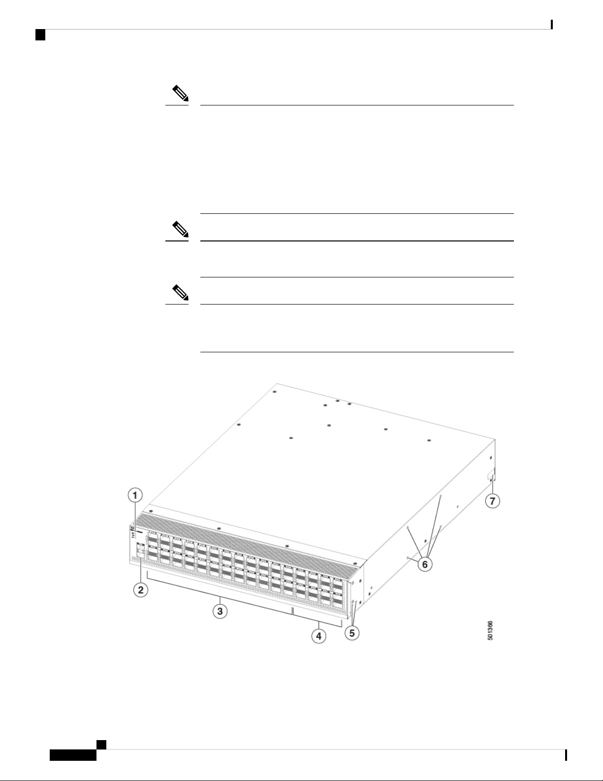
The following figure shows the switch features on the port side of the chassis.
Cisco Nexus 9364C ACI-Mode Switch Hardware Installation Guide
2
Overview
Overview
1
5Beacon (BCN), Status
(STS), and Environment
(ENV) LEDs
Screw holes for front
mounting brackets
(four-post rack
installations)
2
61-/10-Gigabit SFP+ ports
(2)
Screw holes for
center-mount bracket
(two-post rack
installations)
3
740-/100-Gigabit QSFP28
ports (ports 1 to 48 in 4
rows of 12 ports)
Notch on both sides of the
chassis for locking the
power supply end of the
chassis to the bottom
support rails (four-post
rack installations).
4
Green colored
40-/100-Gigabit QSFP28
ports supporting MACsec
(when software support is
available) (ports 49 to 64
in 4 rows of 4 ports)
To determine which transceivers, adapters, and cables are supported by this switch, see the Cisco Transceiver
Modules Compatibility Information document.
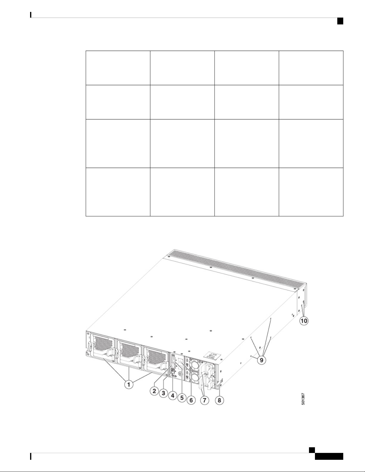
The following figure shows the switch features on the power supply side of the chassis.
Cisco Nexus 9364C ACI-Mode Switch Hardware Installation Guide
3
Overview
Overview
1
Grounding pad6Fan modules (3) with slots
numbered from 1 (left) to
3 (right)
2
7Management port
(1—RJ-45 copper port)
Power supply modules (1
or 2) (AC power supplies
shown) with slots
numbered 1 (top) and 2
(bottom)
3
8Management port
(1—SFP optical port)
Notch on both sides of the
chassis for locking the
power supply end of the
chassis to the bottom
support rails (four-post
rack installations).
9USB port (1)4
Screw holes for
center-mount bracket
(two-post rack
installations)
10Console port (1)5
Screw holes for front
mounting brackets
(four-post rack
installations)
Note
Caution
Depending on whether you plan to position the ports in a hot or cold aisle, you can order the fan and power
supply modules with port-side intake or port-side exhaust airflow. For port-side intake airflow, the fan and
AC power supply modules have burgundy coloring. For port-side exhaust airflow, the fan and AC power
supplies have blue coloring. You can also order the 1200-W HVAC/HVDC power supply which has
dual-direction airflow with white coloring. Dual-direction airflow modules automatically use the airflow
direction of the other modules installed in the switch.
The fan and power supply modules are field replaceable and you can replace one fan module or one power
supply module during operations so long as the other modules are installed and operating. If you have only
one power supply installed, you can install the replacement power supply in the open slot before removing
the original power supply.
All of the fan and power supply modules must have the same direction of airflow. Otherwise, the switch can
overheat and shut down. If you are installing a dual-direction power supply, that module will automatically
use the same airflow direction as the other modules in the switch.
If the switch has port-side intake airflow (burgundy coloring for fan modules), you must locate the ports in
the cold aisle. If the switch has port-side exhaust airflow (blue coloring for fan modules), you must locate the
ports in the hot aisle. If you locate the air intake in a hot aisle, the switch can overheat and shut down.
Cisco Nexus 9364C ACI-Mode Switch Hardware Installation Guide
4

Preparing the Site
• Temperature Requirements, on page 5
• Humidity Requirements, on page 5
• Altitude Requirements, on page 5
• Dust and Particulate Requirements, on page 6
• Minimizing Electromagnetic and Radio Frequency Interference, on page 6
• Shock and Vibration Requirements, on page 7
• Grounding Requirements, on page 7
• Planning for Power Requirements, on page 7
• Airflow Requirements, on page 9
• Rack and Cabinet Requirements, on page 9
• Clearance Requirements, on page 10
Temperature Requirements
The switch requires an operating temperature of 32 to 104 degrees Fahrenheit (0 to 40 degrees Celsius). If
the switch is not operating, the temperature must be between –40 to 158 degrees Fahrenheit (–40 to 70 degrees
Celsius).
CHAPTER 2
Humidity Requirements
High humidity can cause moisture to enter the switch. Moisture can cause corrosion of internal components
and degradation of properties such as electrical resistance, thermal conductivity, physical strength, and size.
The switch is rated to withstand from 5- to 85-percent (non-condensing) relative humidity.
Buildings in which the climate is controlled by air-conditioning in the warmer months and by heat during the
colder months usually maintain an acceptable level of humidity for the switch equipment. However, if the
switch is located in an unusually humid location, you should use a dehumidifier to maintain the humidity
within an acceptable range.
Altitude Requirements
The following table lists the maximum altitude that this switch is tested to operate. This switch is rated to
operate at altitudes from 0 to 13,123 feet (0 to 4,000 meters). If you operate this switch at a higher altitude
Cisco Nexus 9364C ACI-Mode Switch Hardware Installation Guide
5

Dust and Particulate Requirements
(low pressure), the efficiency of forced and convection cooling is reduced and can result in electrical problems
that are related to arcing and corona effects. This condition can also cause sealed components with internal
pressure, such as electrolytic capacitors, to fail or to perform at a reduced efficiency.
Dust and Particulate Requirements
Exhaust fans cool power supplies and system fans cool switches by drawing in air and exhausting air out
through various openings in the chassis. However, fans also ingest dust and other particles, causing contaminant
buildup in the switch and increased internal chassis temperature. A clean operating environment can greatly
reduce the negative effects of dust and other particles, which act as insulators and interfere with the mechanical
components in the switch.
In addition to regular cleaning, follow these precautions to avoid contamination of your switch:
• Do not permit smoking near the switch.
• Do not permit food or drink near the switch.
Preparing the Site
Minimizing Electromagnetic and Radio Frequency Interference
Electromagnetic interference (EMI) and radio frequency interference (RFI) from the switch can adversely
affect other devices, such as radio and television (TV) receivers, operating near the switch. Radio frequencies
that emanate from the switch can also interfere with cordless and low-power telephones. Conversely, RFI
from high-power telephones can cause spurious characters to appear on the switch monitor.
RFI is defined as any EMI with a frequency above 10 kHz. This type of interference can travel from the switch
to other devices through the power cable and power source or through the air as transmitted radio waves. The
Federal Communications Commission (FCC) publishes specific regulations to limit the amount of EMI and
RFI that can be emitted by computing equipment. Each switch meets these FCC regulations.
To reduce the possibility of EMI and RFI, follow these guidelines:
• Cover all open expansion slots with a blank filler plate.
• Always use shielded cables with metal connector shells for attaching peripherals to the switch.
When wires are run for any significant distance in an electromagnetic field, interference can occur between
the field and the signals on the wires with the following implications:
• Bad wiring can result in radio interference emanating from the plant wiring.
• Strong EMI, especially when it is caused by lightning or radio transmitters, can destroy the signal drivers
and receivers in the chassis and even create an electrical hazard by conducting power surges through
lines into equipment.
Note
To predict and prevent strong EMI, you might need to consult experts in radio frequency interference (RFI).
The wiring is unlikely to emit radio interference if you use twisted-pair cable with a good distribution of
grounding conductors. If you exceed the recommended distances, use a high-quality twisted-pair cable with
one ground conductor for each data signal when applicable.
Cisco Nexus 9364C ACI-Mode Switch Hardware Installation Guide
6

Preparing the Site
Shock and Vibration Requirements
Caution
If the wires exceed the recommended distances, or if wires pass between buildings, give special consideration
to the effect of a lightning strike in your vicinity. The electromagnetic pulse caused by lightning or other
high-energy phenomena can easily couple enough energy into unshielded conductors to destroy electronic
switches. You might want to consult experts in electrical surge suppression and shielding if you had similar
problems in the past.
Shock and Vibration Requirements
The switch has been shock- and vibration-tested for operating ranges, handling, and earthquake standards.
Grounding Requirements
The switch is sensitive to variations in voltage supplied by the power sources. Overvoltage, undervoltage,
and transients (or spikes) can erase data from memory or cause components to fail. To protect against these
types of problems, ensure that there is an earth-ground connection for the switch. You can connect the grounding
pad on the switch either directly to the earth-ground connection or to a fully bonded and grounded rack.
When you properly install the chassis in a grounded rack, the switch is grounded because it has a metal-to-metal
connection to the rack. Alternatively, you can ground the chassis by using a customer-supplied grounding
cable that meets your local and national installation requirements (we recommend 6-AWG wire for U.S.
installations) connected to the chassis with a grounding lug (provided in the switch accessory kit) and to the
facility ground.
Note
You automatically ground AC power supplies when you connect them to AC power sources. For DC power
supplies, you must connect a grounding wire when wiring the power supply to the DC power source.
Planning for Power Requirements
The switch includes two power supplies (1-to-1 redundancy with current sharing) in one of the following
combinations:
• Two 1200-W AC power supplies
• Two 1200-W HVAC/HVDC power supplies
• Two 930-W DC power supplies
Note
For n+1 redundancy, you can use one or two power sources for the two power supplies. For n+n redundancy,
you must use two power sources and connect each power supply to a separate power source.
Cisco Nexus 9364C ACI-Mode Switch Hardware Installation Guide
7
Planning for Power Requirements
The power supplies are rated to output up to either 1200 W (AC and HVAC/HVDC power supplies) or 930
W (DC power supplies) to the switch, but the switch requires less than those amounts of power from the power
supply. To operate the switch you must provision enough power from the power source to cover the
requirements of both the switch and a power supply. Typically, this switch and a power supply require about
429 W of power input from the power source, but you must provision as much as 1245 W power input from
the power source to cover peak demand.
Note
Some of the power supply modules have Underwriter Labs (UL) rating capabilities that exceed the switch
requirements. When calculating power requirements, use the switch requirements to determine the amount
of power required for the power supplies.
To minimize the possibility of circuit failure, make sure that each power-source circuit used by the switch is
dedicated to the switch.
Note
For AC input application, please refer to the statement below:
Preparing the Site
Warning
Note
Warning
Note
Statement 1005—Circuit Breaker
This product relies on the building's installation for short-circuit (overcurrent) protection. Ensure that the
protective devices are rated not greater than 20A (North America), 16A (Europe), and 13A (UK).
For DC input application, please refer to the statement below:
Statement 1005—Circuit Breaker
This product relies on the building's installation for short-circuit (overcurrent) protection.
• Ensure that the protective devices are rated not greater than 40A when the switch is powered with regular
DC power supplies (rated 48-60VDC).
• Ensure that the protective devices are rated not greater than 10A when the switch is powered with HVDC
power supplies (rated 240-350VDC).
For the power cables to use with the power supplies, see Power Cable Specifications, on page 55.
Cisco Nexus 9364C ACI-Mode Switch Hardware Installation Guide
8

Preparing the Site
Airflow Requirements
The switch is designed to be positioned with its ports in either the front or the rear of the rack depending on
your cabling and maintenance requirements. Depending on which side of the switch faces the cold aisle, you
must have fan and power supply modules that move the coolant air from the cold aisle to the hot aisle in one
of the following ways:
• Port-side exhaust airflow—Coolant air enters the chassis through the fan and power supply modules in
the cold aisle and exhausts through the port end of the chassis in the hot aisle.
• Port-side intake airflow—Coolant air enters the chassis through the port end in the cold aisle and exhausts
through the fan and power supply modules in the hot aisle.
• Dual-direction airflow—Airflow direction is determined by the airflow direction of the installed fan
modules.
You can identify the airflow direction of each fan and power supply module by its coloring as follows:
• Blue coloring indicates port-side exhaust airflow.
Airflow Requirements
• Burgundy coloring indicates port-side intake airflow.
• White coloring on HVAC/HVDC power supplies indicates dual-direction airflow.
Note
To prevent the switch from overheating and shutting down, you must position the air intake for the switch in
a cold aisle, and all of the fan and power supply modules must have the same direction of airflow (even if
their coloring is different). If you must change the airflow direction for the switch, you must shutdown the
switch before changing the modules.
Rack and Cabinet Requirements
You can install the following types of racks or cabinets for your switch:
• Standard perforated cabinets
• Solid-walled cabinets with a roof fan tray (bottom-to-top cooling)
• Standard open four-post Telco racks
• Standard open two-post Telco racks
Work with your cabinet vendors to determine which of their cabinets meet the following requirements or see
the Cisco Technical Assistance Center (TAC) for recommendations:
• Use a standard 19-inch (48.3-cm), four-post Electronic Industries Alliance (EIA) cabinet or rack with
mounting rails that conform to English universal hole spacing per section 1 of the ANSI/EIA-310-D-1992
standard.
• The depth of a four-post rack must be 24 to 32 inches (61.0 to 81.3 cm) between the front and rear
mounting rails (for proper mounting of the bottom-support brackets or other mounting hardware).
Cisco Nexus 9364C ACI-Mode Switch Hardware Installation Guide
9
Clearance Requirements
Preparing the Site
• Required clearances between the chassis and the edges of its rack or the interior of its cabinet are as
follows:
• 4.5 inches (11.4 cm) between the front of the chassis and the interior of the cabinet (required for
cabling).
• 3.0 inches (7.6 cm) between the rear of the chassis and the interior of the cabinet (required for airflow
in the cabinet if used).
• No clearance is required between the chassis and the sides of the rack or cabinet (no side airflow).
Additionally, you must have power receptacles located within reach of the power cords used with the switch.
Warning
Statement 1048—Rack Stabilization
Stability hazard. The rack stabilizing mechanism must be in place, or the rack must be bolted to the floor
before you slide the unit out for servicing. Failure to stabilize the rack can cause the rack to tip over.
Clearance Requirements
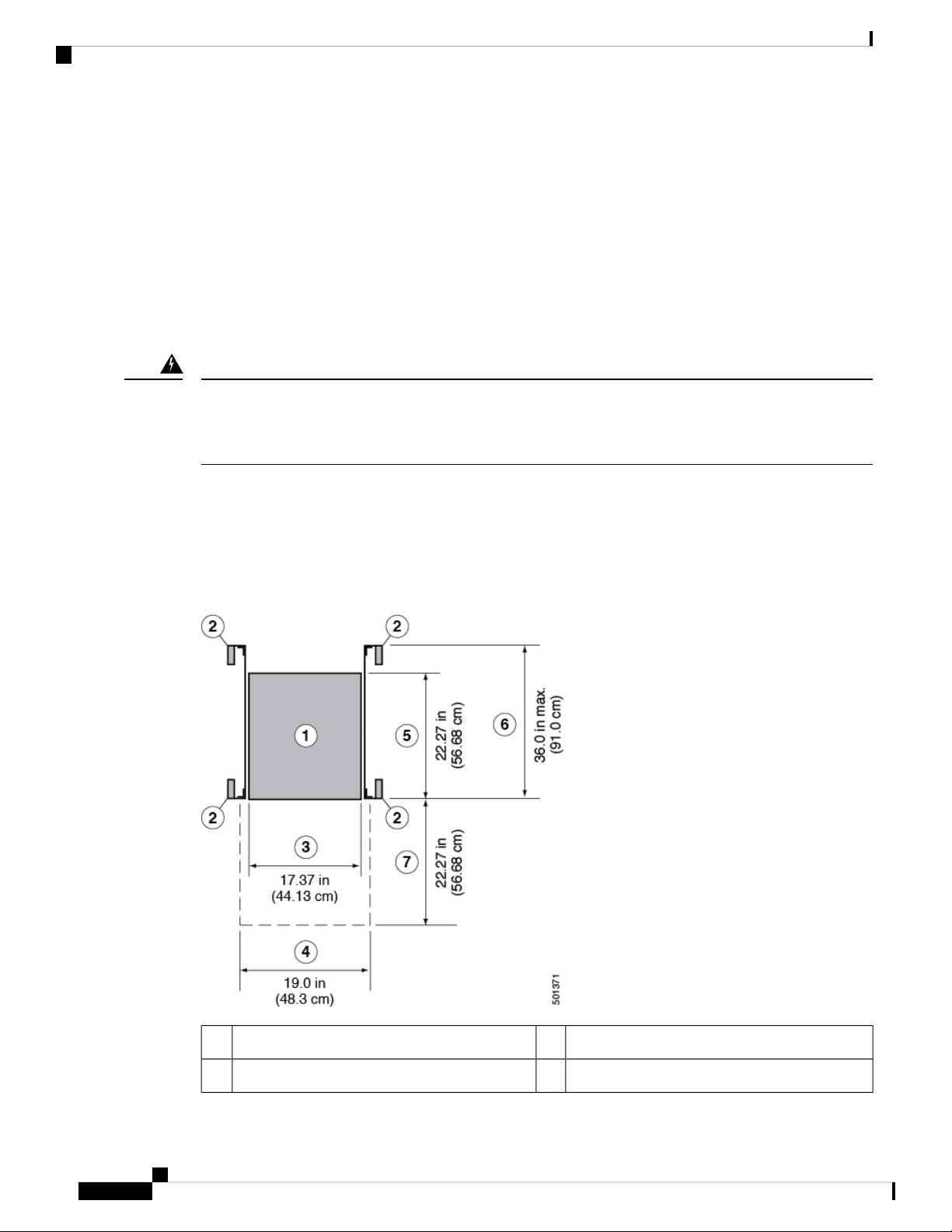
You must provide the chassis with adequate clearance between the chassis and any other rack, device, or
structure so that you can properly install the chassis, route cables, provide airflow, and maintain the switch.
For the clearances required for an installation of this chassis in a four-post rack, see the following figure.
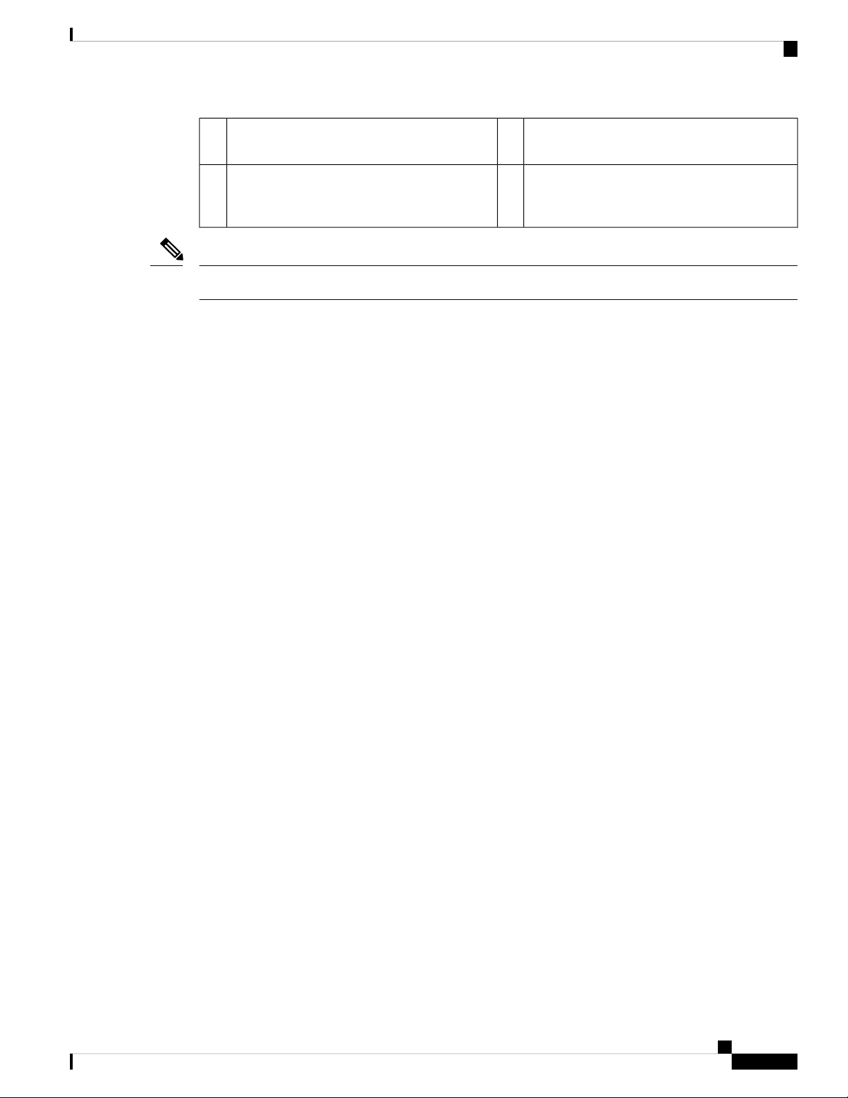
Depth of the chassis5Chassis1
Maximum extension of the bottom-support rails6Vertical rack-mount posts and rails2
Cisco Nexus 9364C ACI-Mode Switch Hardware Installation Guide
10
Preparing the Site
Depth of the front clearance area (this equals the
7Chassis width3
depth of the chassis)
Width of the front clearance area (this equals the
4
width of the chassis with two rack-mount
brackets attached to it)
Note
Both the front and rear of the chassis must be open to both aisles for airflow.
Clearance Requirements
Cisco Nexus 9364C ACI-Mode Switch Hardware Installation Guide
11

Clearance Requirements
Preparing the Site
Cisco Nexus 9364C ACI-Mode Switch Hardware Installation Guide
12

CHAPTER 3
Installing the Chassis
• Install a Rack, on page 13
• Unpacking and Inspecting a New Switch, on page 14
• Planning How to Position the Chassis in the Rack, on page 15
• Installing the Chassis in a Two-Post Rack, on page 15
• Installing the Chassis in a Four-Post Rack, on page 19
• Grounding the Chassis, on page 23
• Powering Up the Switch, on page 25
Install a Rack
Before you install the switch, you must install a standard two- or four-post, 19-inch EIA data center rack (or
a cabinet that contains such a rack) that meets the requirements listed in Overview of Racks, on page 49.
Step 1 Bolt the rack to the concrete subfloor before moving the chassis onto it.
Warning
Step 2 If the rack has bonded construction, connect it to the earth ground. This action enables you to easily ground the switch
and its components and to ground your electrostatic discharge (ESD) wrist strap to prevent damaging discharges when
you handle ungrounded components before installing them.
Step 3 Include one or two power sources at the rack. For AC power, provide a power receptacle. For DC power, provide a circuit
breaker with terminals for connecting power cables.
Warning
Note
Statement 1048—Rack Stabilization
Stability hazard. The rack stabilizing mechanism must be in place, or the rack must be bolted to the floor before
you slide the unit out for servicing. Failure to stabilize the rack can cause the rack to tip over.
Statement 1018—Supply Circuit
Take care when connecting units to the supply circuit so that wiring is not overloaded.
If you are not using power redundancy or are using n+1 redundancy, you need only one power source. If you
are using n+n redundancy, you need two power sources.
Cisco Nexus 9364C ACI-Mode Switch Hardware Installation Guide
13
 Loading...