

Page 1

Cisco Nexus 9336C-FX2 ACI-Mode Switch Hardware Installation Guide
First Published: 2017-10-31
Last Modified: 2018-03-01
Americas Headquarters
Cisco Systems, Inc.
170 West Tasman Drive
San Jose, CA 95134-1706
USA
http://www.cisco.com
Tel: 408 526-4000
800 553-NETS (6387)
Fax: 408 527-0883
Page 2

©
2017 Cisco Systems, Inc. All rights reserved.
Page 3

CONTENTS
PREFACE
CHAPTER 1
CHAPTER 2
Preface vii
Audience vii
Documentation Conventions vii
Documentation Feedback viii
Obtaining Documentation and Submitting a Service Request viii
Overview 1
Overview 1
Preparing the Site 5
Temperature Requirements 5
Humidity Requirements 5
Altitude Requirements 5
Dust and Particulate Requirements 6
Minimizing Electromagnetic and Radio Frequency Interference 6
Shock and Vibration Requirements 7
CHAPTER 3
Grounding Requirements 7
Planning for Power Requirements 7
Airflow Requirements 8
Rack and Cabinet Requirements 9
Clearance Requirements 10
Installing the Switch Chassis 11
Safety 11
Installation Options with Racks and Cabinets 12
Airflow Considerations 12
Cisco Nexus 9336C-FX2 ACI-Mode Switch Hardware Installation Guide
iii
Page 4

Contents
Installation Guidelines 12
Unpacking and Inspecting the Switch 13
Installing the Switch 14
Grounding the Chassis 18
Starting the Switch 20
CHAPTER 4
CHAPTER 5
Connecting the Switch to the ACI Fabric 23
ACI Fabric Topology 23
Preparing to Connect to Other Devices 24
Connecting Leaf Switches to APICs 25
Connecting Leaf Switches to Spine Switches 26
Setting Up an Optional Console Interface 29
Setting Up an Optional Management Connection 30
Maintaining Transceivers and Optical Cables 30
Replacing Components 33
Replacing a Fan Module 33
Removing a Fan Module 33
Installing a Fan Module 34
Replacing a Power Supply Module 35
Replacing an AC Power Supply 35
Replacing a High Voltage (HVAC/HVDC) Power Supply 36
APPENDIX A
APPENDIX B
iv
Replacing a DC Power Supply 38
Rack Specifications 41
Overview of Racks 41
General Requirements for Cabinets and Racks 41
Requirements Specific to Standard Open Racks 42
Requirements Specific to Perforated Cabinets 42
Cable Management Guidelines 42
System Specifications 43
Environmental Specifications 43
Switch Dimensions 43
Cisco Nexus 9336C-FX2 ACI-Mode Switch Hardware Installation Guide
Page 5

Switch and Module Weights and Quantities 44
Transceiver and Cable Specifications 44
Switch Power Input Requirements 44
Power Specifications 45
1100-W AC Power Supply Specifications 45
Power Cable Specifications 46
Power Cable Specifications for AC Power Supplies 46
HVAC/HVDC Power Cables Supported by ACI-Mode and NX-OS Mode Switches 47
Regulatory Standards Compliance Specifications 47
Contents
APPENDIX C
APPENDIX D
APPENDIX E
LEDs 49
Switch Chassis LEDs 49
Lane Link LEDs 50
Fan Module LEDs 50
Power Supply LEDs 50
Additional Kits 53
Accessory Kit 53
Site Preparation and Maintenance Records 55
Site Preparation Checklist 55
Contact and Site Information 56
Chassis and Module Information 57
Cisco Nexus 9336C-FX2 ACI-Mode Switch Hardware Installation Guide
v
Page 6

Contents
Cisco Nexus 9336C-FX2 ACI-Mode Switch Hardware Installation Guide
vi
Page 7
Preface
• Audience, on page vii
• Documentation Conventions, on page vii
• Documentation Feedback, on page viii
• Obtaining Documentation and Submitting a Service Request, on page viii
Audience
This publication is for network administrators who install, configure, and maintain Cisco Nexus switches.
Documentation Conventions
Command descriptions use the following conventions:
bold
DescriptionConvention
Bold text indicates the commands and keywords that you enter literally
as shown.
Italic
[x | y]
{x | y}
[x {y | z}]
variable
Italic text indicates arguments for which the user supplies the values.
Square brackets enclose an optional element (keyword or argument).[x]
Square brackets enclosing keywords or arguments separated by a vertical
bar indicate an optional choice.
Braces enclosing keywords or arguments separated by a vertical bar
indicate a required choice.
Nested set of square brackets or braces indicate optional or required
choices within optional or required elements. Braces and a vertical bar
within square brackets indicate a required choice within an optional
element.
Indicates a variable for which you supply values, in context where italics
cannot be used.
Cisco Nexus 9336C-FX2 ACI-Mode Switch Hardware Installation Guide
vii
Page 8
Documentation Feedback
Preface
DescriptionConvention
string
Examples use the following conventions:
italic screen font
!, #
Documentation Feedback
To provide technical feedback on this document, or to report an error or omission, please send your comments
to . We appreciate your feedback.
A nonquoted set of characters. Do not use quotation marks around the
string or the string will include the quotation marks.
DescriptionConvention
Terminal sessions and information the switch displays are in screen font.screen font
Information you must enter is in boldface screen font.boldface screen font
Arguments for which you supply values are in italic screen font.
Nonprinting characters, such as passwords, are in angle brackets.< >
Default responses to system prompts are in square brackets.[ ]
An exclamation point (!) or a pound sign (#) at the beginning of a line
of code indicates a comment line.
Obtaining Documentation and Submitting a Service Request
For information on obtaining documentation, using the Cisco Bug Search Tool (BST), submitting a service
request, and gathering additional information, see What's New in Cisco Product Documentation at:
http://www.cisco.com/c/en/us/td/docs/general/whatsnew/whatsnew.html
Subscribe to What’s New in Cisco Product Documentation, which lists all new and revised Cisco technical
documentation as an RSS feed and delivers content directly to your desktop using a reader application. The
RSS feeds are a free service.
viii
Cisco Nexus 9336C-FX2 ACI-Mode Switch Hardware Installation Guide
Page 9

Overview
CHAPTER 1
Overview
• Overview, on page 1
The Cisco Nexus 9336C-FX2 switch (N9K-C9336C-FX2) is a 1-RU, fixed-port switch designed for
spine-leaf-APIC deployment in data centers. This switch has 36 40/100-Gigabit QSFP28 ports. Ports 31-36
support uplink (2 ports needed for minimum uplink, use ports 35-36). All ports support 10-Gigabit with a
QSA adapter (CVR-QSF-SFP10G). Ports 1-30 support 40/100-Gigabit Breakout.
To determine which transceivers, adapters, and cables this switch supports, see the Cisco Transceiver Modules
Compatibility Information document.
This switch includes the following user-replaceable components:
• Fan modules (three) with the following airflow choices:
• Port-side exhaust airflow with blue coloring (NXA-FAN-65CFM-PE)
• Port-side intake airflow with burgundy coloring (NXA-FAN-65CFM-PI)
• Power supply modules (two—one for operations and one for redundancy [1+1]) with the following
choices:
• 1100-W AC power supply with port-side exhaust airflow (blue coloring) (NXA-PAC-1100W-PE2)
• 1100-W AC power supply with port-side intake airflow (burgundy coloring) (NXA-PAC-1100W-PI2)
• 1100-W HVAC/HVDC power supply with port-side exhaust airflow (blue coloring)
(NXA-PHV-1100W-PE)
• 1100-W HVAC/HVDC power supply with port-side intake airflow (burgundy coloring)
(NXA-PHV-1100W-PI)
Note
Both power supplies should use the same type of power source. Do not mix AC
and DC power sources.
Cisco Nexus 9336C-FX2 ACI-Mode Switch Hardware Installation Guide
1
Page 10
Overview
Note
All fan modules and power supplies must use the same airflow direction during
operations.
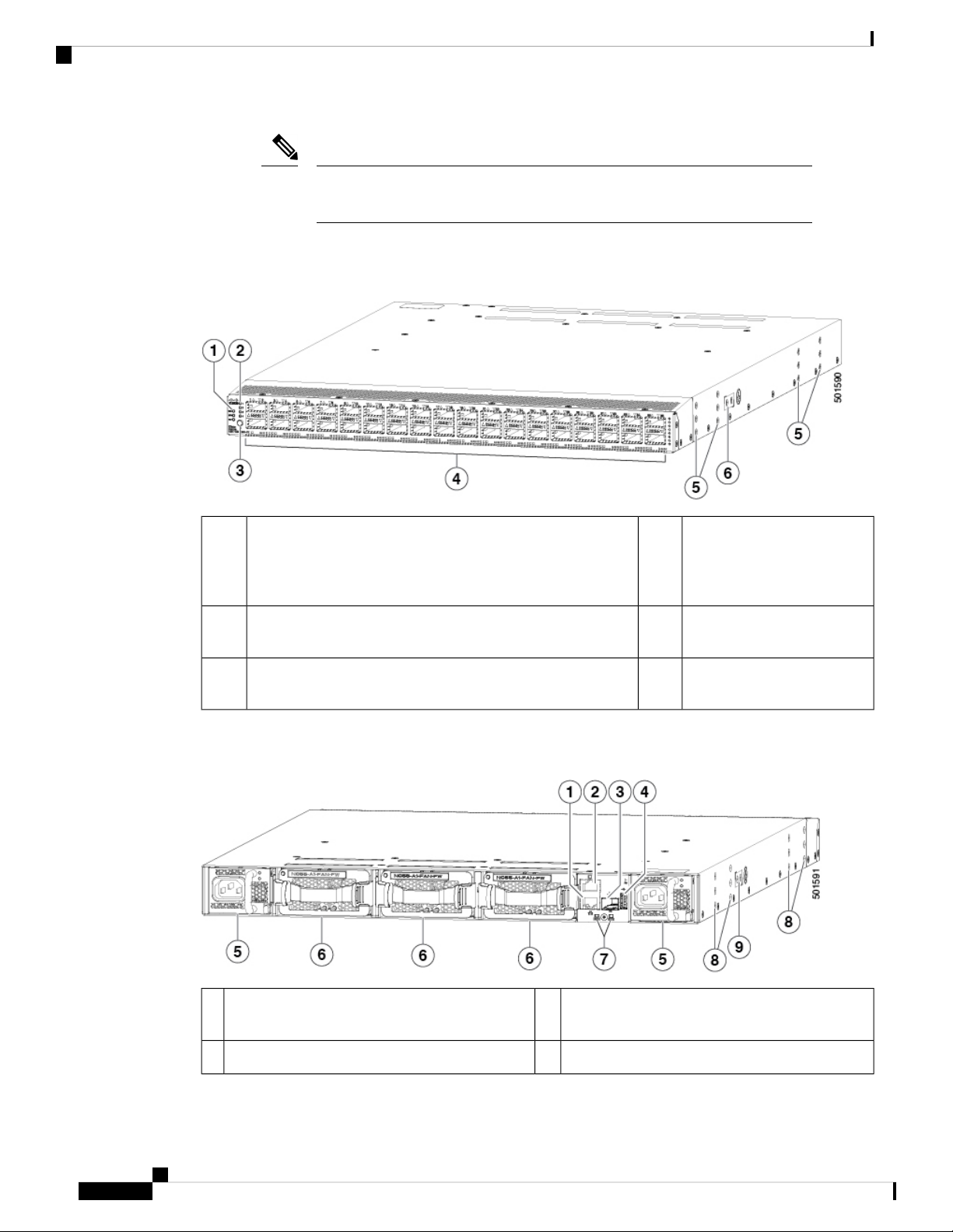
The following figure shows the hardware features seen from the port side of the chassis.
Figure 1: Port Side View of the Cisco Nexus 9336C-FX2 Switch
Overview
36 ports that can be
1
[ENV])
4Chassis LEDs (Beacon [BCN], Status [STS], and Environment
configured differently for
APIC and spine switch
connections
Screw holes (6) for attaching
5Lane selector LEDs2
rack mounting brackets.
Screw holes (2) for attaching
6Lane selection button3
grounding lug.
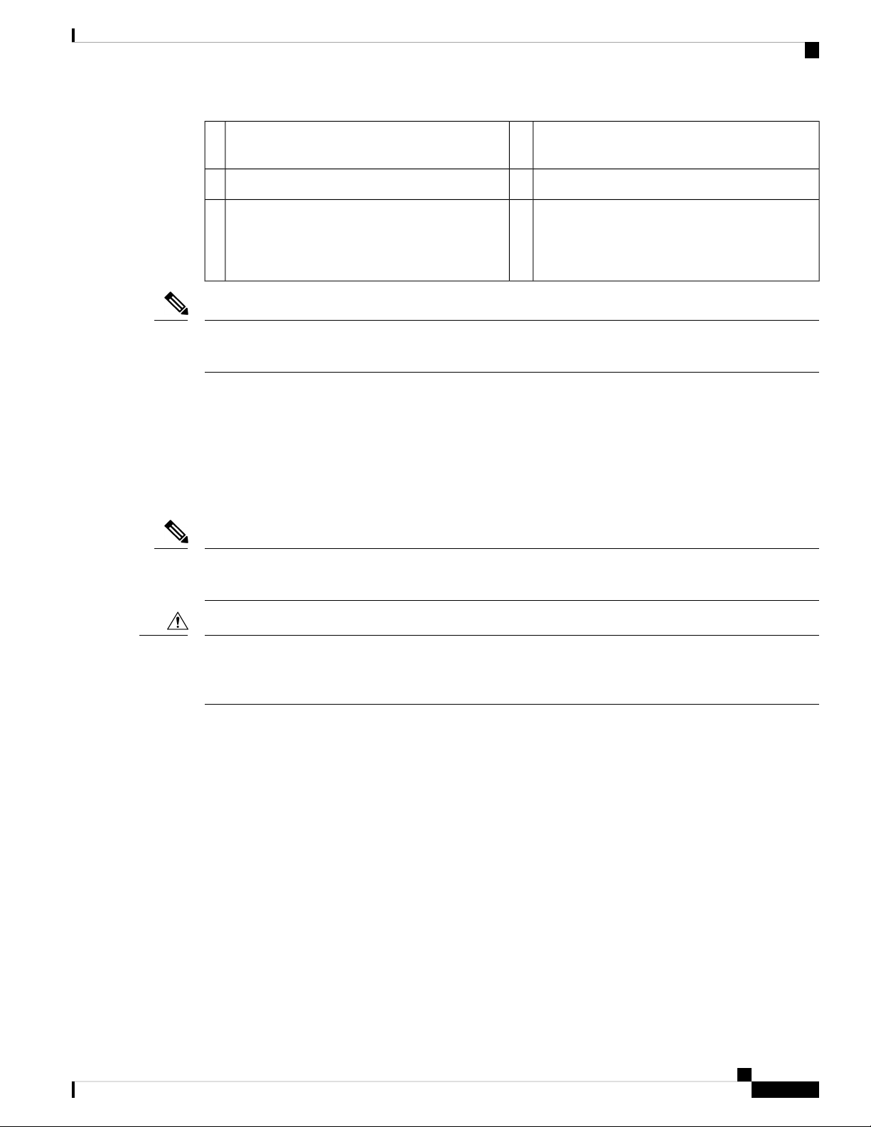
The following figure shows the hardware features seen from the power supply side of the chassis.
Figure 2: Power Supply Side View of the Cisco Nexus 9336C-FX2 Switch
Three fan modules with fan slot 1 on the left and
6Out-of-band management port (SFP port)1
fan slot 3 on the right
Chassis LEDs (Beacon [BCN] and Status [STS])7Console port (RS232 port)2
Cisco Nexus 9336C-FX2 ACI-Mode Switch Hardware Installation Guide
2
Page 11
Overview
Screw holes (6) for attaching rack mounting
8Out-of-band management port (RJ-45 port)3
brackets
Screw holes (2) for attaching grounding lug.9USB port used for saving or copying functions4
Two power supplies (one used for operations and
5
one used for redundancy) (AC power supplies
shown) with power supply slot 1 on the left and
slot 2 on the right
Note
USB support is limited to USB 2.0 devices that use less than 2.5 W (less than 0.5 A inclusive of surge current).
Devices, such as external hard drives, that instantaneously draw more than 0.5 A are not supported.
Depending on whether you plan to position the ports in a hot or cold aisle, you can order the fan and power
supply modules with port-side intake (burgundy colored) or port-side exhaust (blue colored) airflow. All of
the power supply and fan modules must have the same coloring.
Overview
Note
Caution
The fan and power supply modules are field replaceable and you can replace one fan module or one power
supply module during operations so long as the other modules are installed and operating. If you have only
one power supply installed, you can install the replacement power supply in the open slot before removing
the original power supply.
All of the fan and power supply modules must have the same direction of airflow. Otherwise, the switch can
overheat and shut down.
If the switch has port-side intake airflow (burgundy coloring for fan modules), you must locate the ports in
the cold aisle. If the switch has port-side exhaust airflow (blue coloring for fan modules), you must locate the
ports in the hot aisle. If you locate the air intake in a hot aisle, the switch can overheat and shut down.
Cisco Nexus 9336C-FX2 ACI-Mode Switch Hardware Installation Guide
3
Page 12

Overview
Overview
Cisco Nexus 9336C-FX2 ACI-Mode Switch Hardware Installation Guide
4
Page 13

Preparing the Site
• Temperature Requirements, on page 5
• Humidity Requirements, on page 5
• Altitude Requirements, on page 5
• Dust and Particulate Requirements, on page 6
• Minimizing Electromagnetic and Radio Frequency Interference, on page 6
• Shock and Vibration Requirements, on page 7
• Grounding Requirements, on page 7
• Planning for Power Requirements, on page 7
• Airflow Requirements, on page 8
• Rack and Cabinet Requirements, on page 9
• Clearance Requirements, on page 10
Temperature Requirements
The switch requires an operating temperature of 32 to 104 degrees Fahrenheit (0 to 40 degrees Celsius). If
the switch is not operating, the temperature must be between –40 to 158 degrees Fahrenheit (–40 to 70 degrees
Celsius).
CHAPTER 2
Humidity Requirements
High humidity can cause moisture to enter the switch. Moisture can cause corrosion of internal components
and degradation of properties such as electrical resistance, thermal conductivity, physical strength, and size.
The switch is rated to withstand from 5- to 95-percent (non-condensing) relative humidity.
Buildings in which the climate is controlled by air-conditioning in the warmer months and by heat during the
colder months usually maintain an acceptable level of humidity for the switch equipment. However, if the
switch is located in an unusually humid location, you should use a dehumidifier to maintain the humidity
within an acceptable range.
Altitude Requirements
The following table lists the maximum altitude that this switch is tested to operate. This switch is rated to
operate at altitudes from 0 to 10,000 feet (0 to 3,048 meters). If you operate this switch at a higher altitude
Cisco Nexus 9336C-FX2 ACI-Mode Switch Hardware Installation Guide
5
Page 14

Dust and Particulate Requirements
(low pressure), the efficiency of forced and convection cooling is reduced and can result in electrical problems
that are related to arcing and corona effects. This condition can also cause sealed components with internal
pressure, such as electrolytic capacitors, to fail or to perform at a reduced efficiency.
Dust and Particulate Requirements
Exhaust fans cool power supplies and system fans cool switches by drawing in air and exhausting air out
through various openings in the chassis. However, fans also ingest dust and other particles, causing contaminant
buildup in the switch and increased internal chassis temperature. A clean operating environment can greatly
reduce the negative effects of dust and other particles, which act as insulators and interfere with the mechanical
components in the switch.
In addition to regular cleaning, follow these precautions to avoid contamination of your switch:
• Do not permit smoking near the switch.
• Do not permit food or drink near the switch.
Preparing the Site
Minimizing Electromagnetic and Radio Frequency Interference
Electromagnetic interference (EMI) and radio frequency interference (RFI) from the switch can adversely
affect other devices, such as radio and television (TV) receivers, operating near the switch. Radio frequencies
that emanate from the switch can also interfere with cordless and low-power telephones. Conversely, RFI
from high-power telephones can cause spurious characters to appear on the switch monitor.
RFI is defined as any EMI with a frequency above 10 kHz. This type of interference can travel from the switch
to other devices through the power cable and power source or through the air as transmitted radio waves. The
Federal Communications Commission (FCC) publishes specific regulations to limit the amount of EMI and
RFI that can be emitted by computing equipment. Each switch meets these FCC regulations.
To reduce the possibility of EMI and RFI, follow these guidelines:
• Cover all open expansion slots with a blank filler plate.
• Always use shielded cables with metal connector shells for attaching peripherals to the switch.
When wires are run for any significant distance in an electromagnetic field, interference can occur between
the field and the signals on the wires with the following implications:
• Bad wiring can result in radio interference emanating from the plant wiring.
• Strong EMI, especially when it is caused by lightning or radio transmitters, can destroy the signal drivers
and receivers in the chassis and even create an electrical hazard by conducting power surges through
lines into equipment.
Note
To predict and prevent strong EMI, you might need to consult experts in radio frequency interference (RFI).
The wiring is unlikely to emit radio interference if you use twisted-pair cable with a good distribution of
grounding conductors. If you exceed the recommended distances, use a high-quality twisted-pair cable with
one ground conductor for each data signal when applicable.
Cisco Nexus 9336C-FX2 ACI-Mode Switch Hardware Installation Guide
6
Page 15
Preparing the Site
Shock and Vibration Requirements
Caution
If the wires exceed the recommended distances, or if wires pass between buildings, give special consideration
to the effect of a lightning strike in your vicinity. The electromagnetic pulse caused by lightning or other
high-energy phenomena can easily couple enough energy into unshielded conductors to destroy electronic
switches. You might want to consult experts in electrical surge suppression and shielding if you had similar
problems in the past.
Shock and Vibration Requirements
The switch has been shock- and vibration-tested for operating ranges, handling, and earthquake standards.
Grounding Requirements
The switch is sensitive to variations in voltage supplied by the power sources. Overvoltage, undervoltage,
and transients (or spikes) can erase data from memory or cause components to fail. To protect against these
types of problems, ensure that there is an earth-ground connection for the switch. You can connect the grounding
pad on the switch either directly to the earth-ground connection or to a fully bonded and grounded rack.
When you properly install the chassis in a grounded rack, the switch is grounded because it has a metal-to-metal
connection to the rack. Alternatively, you can ground the chassis by using a customer-supplied grounding
cable that meets your local and national installation requirements (we recommend 6-AWG wire for U.S.
installations) connected to the chassis with a grounding lug (provided in the switch accessory kit) and to the
facility ground.
Note
You automatically ground AC power supplies when you connect them to AC power sources. For DC power
supplies, you must connect a grounding wire when wiring the power supply to the DC power source.
Planning for Power Requirements
The switch includes two power supplies (1-to-1 redundancy with current sharing) in one of the following
combinations:
• Two 1100-W AC power supplies
• Two 1100-W HVAC/HVDC power supplies
Note
Both power supplies must be the same type. Do not mix AC and DC power supplies in the same chassis.
Note
For n+1 redundancy, you can use one or two power sources for the two power supplies. For n+n redundancy,
you must use two power sources and connect each power supply to a separate power source.
Cisco Nexus 9336C-FX2 ACI-Mode Switch Hardware Installation Guide
7
Page 16
Airflow Requirements
Note
Note
Preparing the Site
The power supplies are rated to output up to 1100 W, but the switch requires less than those amounts of power
from the power supply. To operate the switch you must provision enough power from the power source to
cover the requirements of both the switch and a power supply. Typically, this switch and a power supply
require about 367 W of power input from the power source, but you must provision as much as 777 W power
input from the power source to cover peak demand.
Some of the power supply modules have Underwriter Labs (UL) rating capabilities that exceed the switch
requirements. When calculating power requirements, use the switch requirements to determine the amount
of power required for the power supplies.
To minimize the possibility of circuit failure, make sure that each power-source circuit used by the switch is
dedicated to the switch.
For AC input application, please refer to the statement below:
Warning
Note
Warning
Note
Statement 1005—Circuit Breaker
This product relies on the building's installation for short-circuit (overcurrent) protection. Ensure that the
protective devices are rated not greater than 20A (North America), 16A (Europe), and 13A (UK).
For DC input application, please refer to the statement below:
Statement 1005—Circuit Breaker
This product relies on the building's installation for short-circuit (overcurrent) protection.
• Ensure that the protective devices are rated not greater than 40A when the switch is powered with regular
DC power supplies (rated 48-60VDC).
• Ensure that the protective devices are rated not greater than 10A when the switch is powered with HVDC
power supplies (rated 240-350VDC).
For the power cables to use with the power supplies, see Power Cable Specifications, on page 46.
Airflow Requirements
The switch is designed to be positioned with its ports in either the front or the rear of the rack depending on
your cabling and maintenance requirements. Depending on which side of the switch faces the cold aisle, you
Cisco Nexus 9336C-FX2 ACI-Mode Switch Hardware Installation Guide
8
Page 17
Preparing the Site
Rack and Cabinet Requirements
must have fan and power supply modules that move the coolant air from the cold aisle to the hot aisle in one
of the following ways:
• Port-side exhaust airflow—Coolant air enters the chassis through the fan and power supply modules in
the cold aisle and exhausts through the port end of the chassis in the hot aisle.
• Port-side intake airflow—Coolant air enters the chassis through the port end in the cold aisle and exhausts
through the fan and power supply modules in the hot aisle.
You can identify the airflow direction of each fan and power supply module by its coloring as follows:
• Blue coloring indicates port-side exhaust airflow.
• Burgundy coloring indicates port-side intake airflow.
Note
To prevent the switch from overheating and shutting down, you must position the air intake for the switch in
a cold aisle, and all of the fan and power supply modules must have the same direction of airflow (even if
their coloring is different). If you must change the airflow direction for the switch, you must shutdown the
switch before changing the modules.
Rack and Cabinet Requirements
You can install the following types of racks or cabinets for your switch:
• Standard perforated cabinets
• Solid-walled cabinets with a roof fan tray (bottom-to-top cooling)
• Standard open four-post Telco racks
Work with your cabinet vendors to determine which of their cabinets meet the following requirements or see
the Cisco Technical Assistance Center (TAC) for recommendations:
• Use a standard 19-inch (48.3-cm), four-post Electronic Industries Alliance (EIA) cabinet or rack with
mounting rails that conform to English universal hole spacing per section 1 of the ANSI/EIA-310-D-1992
standard.
• The depth of a four-post rack must be 24 to 32 inches (61.0 to 81.3 cm) between the front and rear
mounting rails (for proper mounting of the bottom-support brackets or other mounting hardware).
Additionally, you must have power receptacles located within reach of the power cords used with the switch.
Warning
Statement 1048—Rack Stabilization
Stability hazard. The rack stabilizing mechanism must be in place, or the rack must be bolted to the floor
before you slide the unit out for servicing. Failure to stabilize the rack can cause the rack to tip over.
Cisco Nexus 9336C-FX2 ACI-Mode Switch Hardware Installation Guide
9
Page 18
Clearance Requirements
Clearance Requirements
You must provide the chassis with adequate clearance between the chassis and any other rack, device, or
structure so that you can properly install the chassis, route cables, provide airflow, and maintain the switch.
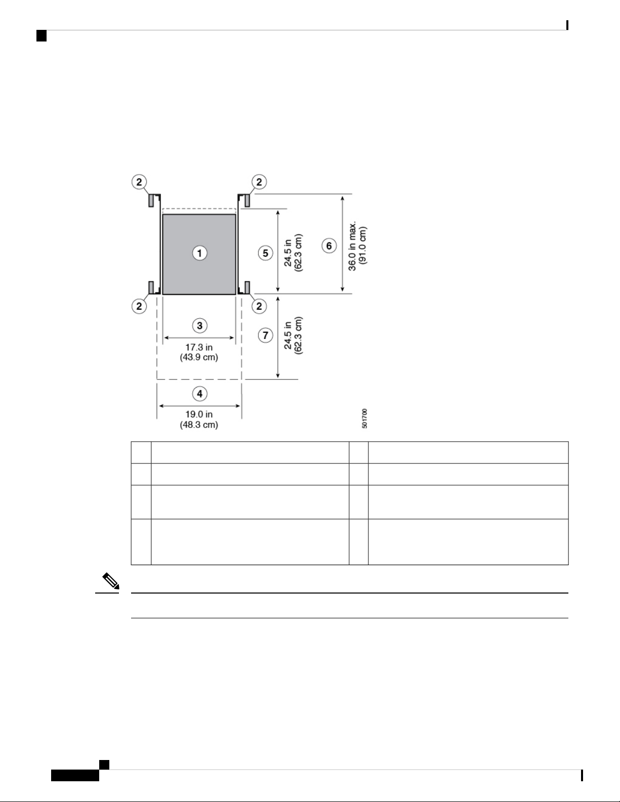
For the clearances required for an installation of this chassis in a four-post rack, see the following figure.
Preparing the Site
Depth of the chassis5Chassis1
Maximum extension of the bottom-support rails6Vertical rack-mount posts and rails2
Depth of the front clearance area (this equals the
7Chassis width3
depth of the chassis)
Width of the front clearance area (this equals the
4
width of the chassis with two rack-mount
brackets attached to it)
Note
Both the front and rear of the chassis must be open to both aisles for airflow.
Cisco Nexus 9336C-FX2 ACI-Mode Switch Hardware Installation Guide
10
Page 19
Safety
CHAPTER 3
Installing the Switch Chassis
• Safety, on page 11
• Installation Options with Racks and Cabinets, on page 12
• Airflow Considerations, on page 12
• Installation Guidelines, on page 12
• Unpacking and Inspecting the Switch, on page 13
• Installing the Switch, on page 14
• Grounding the Chassis, on page 18
• Starting the Switch, on page 20
Before you install, operate, or service the switch, see the Regulatory, Compliance, and Safety Information for
the Cisco Nexus 3000 and 9000 Series for important Safety Information.
Warning
Warning
Statement 1071—Warning Definition
IMPORTANT SAFETY INSTRUCTIONS
This warning symbol means danger. You are in a situation that could cause bodily injury. Before you work
on any equipment, be aware of the hazards involved with electrical circuitry and be familiar with standard
practices for preventing accidents. Use the statement number provided at the end of each warning to locate
its translation in the translated safety warnings that accompanied this device.
SAVE THESE INSTRUCTIONS
Statement 1017—Restricted Area
This unit is intended for installation in restricted access areas. A restricted access area can be accessed only
through the use of a special tool, lock and key, or other means of security.
Cisco Nexus 9336C-FX2 ACI-Mode Switch Hardware Installation Guide
11
Page 20

Installation Options with Racks and Cabinets
Installing the Switch Chassis
Warning
Statement 1030—Equipment Installation
Only trained and qualified personnel should be allowed to install, replace, or service this equipment.
Installation Options with Racks and Cabinets
You can install the switch in the following types of racks using the rack-mount kit shipped with the switch:
• Open EIA rack
• Perforated EIA cabinet
The rack or cabinet that you use must meet the requirements listed in General Requirements for Cabinets and
Racks, on page 41.
The rack-mount kit enables you to install the switch into racks of varying depths. You can use the rack-mount
kit parts to position the switch with easy access to either the port connections end of the chassis or the end of
the chassis with the fan and power supply modules. For instructions on how to install the rack-mount kit, see
the Installing the Switch, on page 14.
Airflow Considerations
The switch comes with fan and power supply modules that have either port-side intake or port-side exhaust
airflow for cooling the switch. If you are positioning the port end of the switch in a cold aisle, make sure that
the switch has port-side intake fan modules with burgundy coloring. If you are positioning the fan and power
supply modules in a cold aisle, make sure that the switch has port-side exhaust fan modules with blue colorings.
All fan modules must have the same direction of airflow.
Installation Guidelines
When installing the switch, follow these guidelines:
• Record equipment and installation information in the forms presented in Chassis and Module Information
as you install and configure the switch.
• Ensure that there is adequate clearance space around the switch to allow for servicing the switch and for
adequate airflow.
• Ensure that the chassis can be adequately grounded. If the switch is not mounted in a grounded rack, we
recommend connecting both the system ground on the chassis directly to an earth ground.
• Ensure that the site power meets the power requirements for the switch. If available, you can use an
uninterruptible power supply (UPS) to protect against power failures.
Cisco Nexus 9336C-FX2 ACI-Mode Switch Hardware Installation Guide
12
Page 21

Installing the Switch Chassis
Unpacking and Inspecting the Switch
Caution
Avoid UPS types that use ferroresonant technology. These UPS types can become
unstable with the switch, which can have substantial current draw fluctuations
because of fluctuating data traffic patterns.
• Ensure that circuits are sized according to local and national codes. Typically, this often requires one or
both of the following:
• AC power supplies typically require at least a 15-A or 20-A AC circuit, 100 to 240 VAC, and a
frequency of 50 to 60 Hz.
• HVAC/HVDC power supplies require the following:
• HVAC input voltage range of 100 to 277 VAC with a frequency of 50 to 60 Hz
• HVDC input voltage range of -240 to -380 VDC
Caution
To prevent loss of input power, ensure the total maximum loads on the circuits
supplying power to the switch are within the current ratings for the wiring and
breakers.
Unpacking and Inspecting the Switch
Before you install the switch, be sure to unpack and inspect the switch for damage or missing components.
If anything is missing or damaged, contact your customer service representative immediately.
Tip
Keep the shipping container in case the chassis requires shipping at a later time.
Before you begin
Before you unpack the switch and before you handle any switch components, be sure that you are wearing a
grounded electrostatic discharge (ESD) strap. To ground the strap, attach it directly to an earth ground or to
a grounded rack or grounded chassis (there must be a metal-to-metal connection to the earth ground).
Step 1 Compare the shipment to the equipment list provided by your customer service representative and verify that you have
received all items, including the following:
• Accessory Kit
Note
For the contents of these kits, see the Additional Kits.
Step 2 Check for damage and report any discrepancies or damage to your customer service representative. Have the following
information ready:
• Invoice number of shipper (see packing slip)
Cisco Nexus 9336C-FX2 ACI-Mode Switch Hardware Installation Guide
13
Page 22

Installing the Switch Chassis
Installing the Switch
• Model and serial number of the damaged unit
• Description of damage
• Effect of damage on the installation
Step 3 Check to be sure that each of the power supply and the fan tray modules have the expected direction of airflow as follows:
• Port-side intake airflow modules
• Burgundy (fan modules and power supplies)
• Port-side exhaust airflow modules
• Blue (fan modules and power supplies)
Note
All power supplies and fan modules must have the same direction of airflow.
Installing the Switch
To install the switch, you must attach front and rear mounting brackets to the switch, install slider rails on the
rear of the rack, slide the switch onto the slider rails, and secure the switch to the front of the rack. Typically,
the front of the rack is the side easiest to access for maintenance.
Note
You must supply the eight 10-32 or 12-24 screws required to mount the slider rails and switch to the rack.
Before you begin
• You have inspected the switch shipment to ensure that you have everything ordered.
• Make sure that the switch rack-mount kit includes the following parts:
• Front rack-mount brackets (2)
• Rear rack-mount brackets (2)
• Slider rails (2)
• M4 x 0.7 x 8-mm Phillips countersink screws (12)
• The rack is installed and secured to its location.
Step 1 Install two front-mount brackets to the switch as follows:
a) Determine which end of the chassis is to be located in the cold aisle as follows:
• If the switch has port-side intake modules (fan modules with burgundy coloring), position the switch so that its
ports will be in the cold aisle.
Cisco Nexus 9336C-FX2 ACI-Mode Switch Hardware Installation Guide
14
Page 23

Installing the Switch Chassis
• If the switch has port-side exhaust modules (fan modules with blue coloring), position the switch so that its fan
and power supply modules will be in the cold aisle.
b) Position a front-mount bracket so that four of its screw holes are aligned to the screw holes on the side of the chassis.
Installing the Switch
Note
You can align any four of the holes in the front rack-mount bracket to four of the six screw holes on the
side of the chassis (see the two ways to mount these brackets on a typical chassis, in following figure). The
holes that you use depend on the requirements of your rack and the amount of clearance required for interface
cables (3 inches [7.6 mm] minimum) and module handles (1 inch [2.5 mm] minimum).
Figure 3: Attaching Mounting Brackets
1
5Front rack-mount bracket aligned to the port end of
the chassis
2
6Four M4 screws used to attach the bracket to the
chassis
3
7Rear rack-mount guide aligned to the module end of
the chassis
4
8Two M4 screws used to attach the bracket to the
chassis
c) Secure the front-mount bracket to the chassis using four M4 screws and tighten each screw to 12 in-lb (1.36 N·m)
of torque.
d) Repeat Step 1 for the other front rack-mount bracket on the other side of the switch and be sure to position that bracket
the same distance from the front of the switch.
Step 2 Install the two rear rack-mount brackets on the chassis as follows:
Cisco Nexus 9336C-FX2 ACI-Mode Switch Hardware Installation Guide
Front rack-mount bracket aligned to the module end
of the chassis
Four M4 screws used to attach the bracket to the
chassis
Two M4 screws used to attach the bracket to the
chassis
Rear rack-mount guide aligned to the port end of the
chassis
15
Page 24

Installing the Switch Chassis
Installing the Switch
a) Align the two screw holes on a rear rack-mount bracket to the middle two screw holes in the remaining six screw
holes on a side of the chassis. If you are aligning the guide to holes that are near the port connections end of the
chassis, see Callout 3 in the previous figure. Otherwise, see Callout 7 in the previous figure.
b) Attach the guide to the chassis using two M4 screws (see Callout 4 or 8 in the previous figure). Tighten the screws
to 12 in-lb (1.36 N·m) of torque.
c) Repeat Step 2 for the other rear rack-mount bracket on the other side of the switch.
Step 3 If you are not installing the chassis into a grounded rack, you must attach a customer-supplied grounding wire to the
chassis as explained in Grounding the Chassis, on page 18. If you are installing the chassis into a grounded rack, you
can skip this step.
Step 4 Install the slider rails on the rack or cabinet as follows:
a) Determine which two posts of the rack or cabinet you should use for the slider rails. Of the four vertical posts in the
rack or cabinet, two will be used for the front mount brackets attached to the easiest accessed end of the chassis, and
the other two posts will have the slider rails.
b) Position a slider rail at the desired level on the back side of the rack and use two 12-24 screws or two 10-32 screws,
depending on the rack thread type, to attach the rails to the rack (see the following figure). Tighten 12-24 screws to
30 in-lb (3.39 N·m) of torque and tighten 10-32 screws to 20 in-lb (2.26 N·m) of torque.
1
rack
c) Repeat Step 3 to attach the other slider rail to the other side of the rack.
To make sure that the slider rails are at the same level, you should use a level tool, tape measure, or carefully count
the screw holes in the vertical mounting rails.
Step 5 Insert the switch into the rack and attach it as follows:
a) Holding the switch with both hands, position the two rear rack-mount brackets on the switch between the rack or
cabinet posts that do not have slider rails attached to them (see the following figure).
Cisco Nexus 9336C-FX2 ACI-Mode Switch Hardware Installation Guide
16
Two customer-supplied 12-24 or 10-32 screws used
2Slider rail with screw holes aligned to screw holes in
to attach each slider rail to the rack
Page 25

Installing the Switch Chassis
Figure 4: Sliding the Switch onto the Mounting Rails
Installing the Switch
1
Front-mount brackets.3Align the two rear rack-mount bracket guides with
the slider rails installed in the rack.
2
Mounting rails on rack or cabinet posts.4Slide the rack-mount guides onto the slider rails until
the front rack-mount brackets come in contact with
the front rack-mount rails.
b) Align the two rear rack-mount guides on either side of the switch with the slider rails installed in the rack. Slide the
rack-mount guides onto the slider rails, and then gently slide the switch all the way into the rack until the front
rack-mount brackets come in contact with two rack or cabinet posts.
c) Holding the chassis level, insert two screws (12-24 or 10-32, depending on the rack type) in each of the two front
rack-mount brackets (using a total of four screws) and into the cage nuts or threaded holes in the vertical rack-mounting
rails (see the following figure).
Cisco Nexus 9336C-FX2 ACI-Mode Switch Hardware Installation Guide
17
Page 26

Grounding the Chassis
Figure 5: Securing the Switch to the Rack
Installing the Switch Chassis
1
12-24 or 10-32 screws on each side.
Front-mount bracket.2
d) Tighten the 10-32 screws to 20 in-lb (2.26 N·m) or tighten the 12-24 screws to 30 in-lb (3.39 N·m).
Step 6 If you attached a grounding wire to the chassis grounding pad, connect the other end of the wire to the facility ground.
Mounting rails on rack or cabinet posts.3Fasten the chassis to the front of the rack with two
Grounding the Chassis
The switch chassis is automatically grounded when you properly install the switch in a grounded rack with
metal-to-metal connections between the switch and rack.
You can alternatively ground the chassis (this is required if the rack is not grounded) by attaching a
customer-supplied grounding cable to the chassis grounding pad and the facility ground.
Warning
Statement 1024—Ground Conductor
This equipment must be grounded. Never defeat the ground conductor or operate the equipment in the absence
of a suitably installed ground conductor. Contact the appropriate electrical inspection authority or an electrician
if you are uncertain that suitable grounding is available.
Cisco Nexus 9336C-FX2 ACI-Mode Switch Hardware Installation Guide
18
Page 27

Installing the Switch Chassis
Grounding the Chassis
Warning
Statement 1046—Installing or Replacing the Unit
When installing or replacing the unit, the ground connection must always be made first and disconnected last.
Before you begin
Before you can ground the chassis, you must have a connection to the earth ground for the data center building.
Step 1 Use a wire-stripping tool to remove approximately 0.75 inch (19 mm) of the covering from the end of the grounding
wire.
Step 2 Insert the stripped end of the grounding wire into the open end of the grounding lug, and use a crimping tool to crimp
the lug to the wire (see Callout 2 in the following figure). Verify that the ground wire is securely attached to the grounding
lug by attempting to pull the wire out of the crimped lug.
Figure 6: Grounding the Switch.
3Chassis grounding pad1
2 M4 screws used to secure
the grounding lug to the
chassis
2
Grounding cable, with 0.75
in. (19 mm) of insulation
stripped from one end,
inserted into the grounding
lug and crimped in place
Cisco Nexus 9336C-FX2 ACI-Mode Switch Hardware Installation Guide
19
Page 28

Installing the Switch Chassis
Starting the Switch
Step 3 Secure the grounding lug to the chassis grounding pad with two M4 screws (see Callouts 1 and 3 in the previous figure),
and tighten the screws to 11 to 15 in-lb (1.24 to 1.69 N·m) of torque.
Starting the Switch
You start the switch by connecting it to its dedicated power source. If you need n+1 redundancy, you must
connect each of the power supplies to one or two power sources. If you need n+n redundancy, you must
connect each power supply in a switch to a different power source.
Before you begin
• The switch must be installed and secured to a rack or cabinet.
• The switch must be adequately grounded.
• The rack must be close enough to the dedicated power source so that you can connect the switch to the
power source by using a designated power cables.
• You have the designated power cables for the power supplies that you are connecting to the dedicated
power sources.
Note
Depending on the outlet receptacle on your AC power distribution unit, you might
need an optional jumper power cord to connect the switch to your outlet receptacle.
• The switch is not connected to the network (this includes any management or interface connections).
• The fan and power supply modules are fully secured in their chassis slots.
All of the fan slots must be filled with fan modules and the power supply slots must be filled with the
same types of power supplies (do not mix AC and DC power supplies).
Step 1 Verify that the power supply LED is on and green.
Step 2 Listen for the fans; they should begin operating when the power supply is powered.
Step 3 After the switch boots, verify that the following LEDs are lit:
• On the fan modules, the Status (STA or STS) LED is green.
If a fan module Status LED is not green, try reinstalling the fan module.
• After initialization, the switch chassis Status (labeled as STA or STS) LED is green.
Step 4 Verify that the system software has booted and the switch has initialized without error messages.
Step 5 Complete the worksheets provided in Site Preparation and Maintenance Records for future reference.
Note
Cisco Nexus 9336C-FX2 ACI-Mode Switch Hardware Installation Guide
20
Page 29

Installing the Switch Chassis
A setup utility automatically launches the first time that you access the switch and guides you through the basic
configuration. For instructions on how to configure the switch and check module connectivity, see the appropriate Cisco
Nexus configuration guide.
Starting the Switch
Cisco Nexus 9336C-FX2 ACI-Mode Switch Hardware Installation Guide
21
Page 30

Starting the Switch
Installing the Switch Chassis
Cisco Nexus 9336C-FX2 ACI-Mode Switch Hardware Installation Guide
22
Page 31

Connecting the Switch to the ACI Fabric
• ACI Fabric Topology, on page 23
• Preparing to Connect to Other Devices, on page 24
• Connecting Leaf Switches to APICs, on page 25
• Connecting Leaf Switches to Spine Switches, on page 26
• Setting Up an Optional Console Interface, on page 29
• Setting Up an Optional Management Connection, on page 30
• Maintaining Transceivers and Optical Cables, on page 30
ACI Fabric Topology
The ACI fabric topology includes the following major components:
• Application Centric Infrastructure Controller (APIC) appliance (cluster of APICs)
• Leaf switches (Cisco Nexus 93108TC-EX, 93108TC-FX, 93120TX, 93128TX, 93180LC-EX,
93180YC-EX, 93180YC-FX, 9332PQ, 9336C-FX2, 9348GC-FXP, 9372PX, 9372PX-E, 9372TX,
9372TX-E, 9396PX, and 9396TX switches)
CHAPTER 4
• Spine switches (Cisco Nexus 9336PQ, 9364C, 9504, 9508, and 9516 switches)
As shown in the following figure, each APIC is connected to one or two leaf switches and each leaf switch
should be connected to every spine switch in the same fabric.
Note
To prevent sub-optimal forwarding between endpoints, connect every leaf switch in the fabric to every spine
switch in the same fabric.
Cisco Nexus 9336C-FX2 ACI-Mode Switch Hardware Installation Guide
23
Page 32

Preparing to Connect to Other Devices
Figure 7: Connections Between APIC Clusters, Leaf Nodes, and Spine Nodes
Connecting the Switch to the ACI Fabric
Preparing to Connect to Other Devices
When preparing to connect the fabric devices, consider the following for each type of interface, and gather
all of the required equipment before making the connections:
• Cabling type required for each interface type
• Distance limitations for each signal type
• Additional interface equipment required
Note
When running power and data cables in overhead or subfloor cable trays, we strongly recommend that you
locate power cables and other potential noise sources as far away as practical from network cabling that
terminates on Cisco equipment. In situations where long parallel cable runs cannot be separated by at least
3.3 feet (1 meter), we recommend that you shield any potential noise sources by housing them in a grounded
metallic conduit.
Cisco Nexus 9336C-FX2 ACI-Mode Switch Hardware Installation Guide
24
Page 33

Connecting the Switch to the ACI Fabric
The optical transceivers that are not already assembled to their cables come separate from their cables. To
prevent these transceivers and their cables from being damaged, we recommend that you keep the transceivers
disconnected from their cables when installing them in ports and then insert the optical cable into the transceiver.
When removing transceivers from ports, remove their cables before removing the transceivers.
To maximize the effectiveness and life of your transceivers and optical cables, do the following:
• Wear an ESD-preventative wrist strap that is connected to an earth ground whenever handling transceivers.
The switch is typically grounded when you install transceivers and provides an ESD port to which you
can connect your wrist strap. If you cannot find an ESD port, connect the wrist strap to an earth ground
(such as the grounding connection for the chassis).
• Do not remove or insert a transceiver more often than necessary. Repeated removals and insertions can
shorten its useful life.
• Keep the transceivers and fiber-optic cables clean and dust free to maintain high signal accuracy and to
prevent damage to the connectors. Attenuation (loss of light) increases with contamination and should
be kept below 0.35 dB.
• Clean these parts before installing them to prevent dust from scratching the fiber-optic cable ends.
• Clean the connectors regularly; the required frequency of cleaning depends upon the environment.
Connecting Leaf Switches to APICs
In addition, clean connectors if they are exposed to dust or accidentally touched. Both wet and dry
cleaning techniques can be effective; refer to your site's fiber-optic connection cleaning procedures.
• Do not touch the ends of connectors. Touching the ends can leave fingerprints and cause other
contamination.
• Inspect routinely for dust and damage. If you suspect damage, clean and then inspect fiber ends under a
microscope to determine if damage has occurred.
Connecting Leaf Switches to APICs
You must downlink one or two (recommended for redundancy) ACI-mode leaf switches (Cisco Nexus
93108TC-EX, 93108TC-FX, 93120TX, 93128TX, 93180LC-EX, 93180YC-EX, 93180YC-FX, 9332PQ,
9336C-FX2, 9348GC-FXP, 9372PX, 9372PX-E, 9372TX, 9372TX-E, 9396PX, or 9396TX) to each Application
Policy Infrastructure Controller (APIC) in your ACI fabric. The type of virtual interface card (VIC) installed
on the APIC determines the types of interface cables that you can use to connect the leaf switches to the
APICs.
• The VIC1225 module supports optical transceivers, optical cables, and switches with optical downlink
ports (Cisco Nexus 93180LC-EX, 93180YC-EX, 93180YC-FX, 9332PQ, 9336C-FX2, 9348GC-FXP,
9372PX, 9372PX-E, and 9396PX switches).
• The VIC1225T module supports copper connectors, copper cables, and switches with copper downlink
ports (Cisco Nexus 93108TC-EX, 93108TC-FX, 93120TX, 93128TX, 9372TX, 9372TX-E, and 9396TX
switches).
Before you begin
The APIC and leaf switches in the fabric must be fully installed in their racks and grounded.
Cisco Nexus 9336C-FX2 ACI-Mode Switch Hardware Installation Guide
25
Page 34

Connecting the Switch to the ACI Fabric
Connecting Leaf Switches to Spine Switches
Step 1 Connect an interface cable to one of the two ports on the virtual interface card (VIC) installed on the APIC. If the cable
is not already assembled to its transceivers, insert the transceiver into the VIC port and then connect the optical interface
cable to the transceiver.
• For a VIC1225 optical module, use one of the following sets of transceivers and cables:
• Cisco 10GBASE-LR transceivers (SFP-10G-LR) supporting a link length of up to 6.1 miles (10 km)
• Cisco 10GBASE-SR transceivers (SFP-10G-SR) supporting the following link lengths:
• Using 2000 MHz MMF (OM3) for up to 984 feet (300 m)
• Using 4700 MHz MMF (OM4) for up to 1312 feet (400 m)
• Cisco SFP+ Active Optical Cables (SFP-10G-AOCxM [where x=1, 2, 3, 5, 7, or 10 for lengths in meters])
To determine which transceivers, adapters, and cables are supported by this switch, see
http://www.cisco.com/c/en/us/support/interfaces-modules/transceiver-modules/products-device-support-tables-list.html.
To see the transceiver specifications and installation information, see
http://www.cisco.com/c/en/us/support/interfaces-modules/transceiver-modules/products-installation-guides-list.html.
• For a VIC1225T 10GBASE-T copper module, use 10GBASE-T cables with RJ-45 connectors.
Step 2 Connect the other end of the interface cable to a downlink port on a leaf switch.
• For a Cisco 10GBASE-LR or -SR transceiver and cable, insert the transceiver into a downlink optical port on a leaf
switch before connecting the cable to the transceiver.
• For Cisco SFP+ Active Optical Cables, insert the transceiver on the cable into a downlink optical port on a leaf
switch.
• For a 10GBASE-T copper cable, insert the RJ-45 connector on the cable into a downlink BASE-T port on a leaf
switch.
Note
To determine which transceivers and cables are supported by this switch, see
http://www.cisco.com/c/en/us/support/interfaces-modules/transceiver-modules/products-device-support-tables-list.html.
Connecting Leaf Switches to Spine Switches
For optimal forwarding between endpoints, you must connect each leaf switch (Cisco Nexus 93108TC-EX,
93108TC-FX, 93120TX, 93128TX, 93180LC-EX, 93180YC-EX, 93180YC-FX, 9332PQ, 9336C-FX2,
9348GC-FXP, 9372PX, 9372PX-E, 9372TX, 9372TX-E, 9396PX, or 9396TX) to every spine switch (Cisco
Nexus 9336PQ, 9364C, 9504, 9508, or 9516) in the same ACI fabric. The following table lists the number of
ports that you can connect on each type of leaf switch and the supported speeds for those ports.
Leaf Switch
Default Uplink
Connections
6 QSFP28 fixed portsCisco Nexus 93108TC-EX
Cisco Nexus 9336C-FX2 ACI-Mode Switch Hardware Installation Guide
26
Supported Transmission
Speeds (Uplink Ports)
10, 40, and 100 Gigabits
1
Page 35

Connecting the Switch to the ACI Fabric
Connecting Leaf Switches to Spine Switches
Leaf Switch
Cisco Nexus 93128TX
uplink module
with M12PQ uplink
module
Default Uplink
Connections
6 QSFP+ portswith M6PQ or M4PQ-E
8 QSFP+ ports (leftmost
8 ports are supported on
12-port module)
6 QSFP28 fixed portsCisco Nexus 93180YC-EX
6 QSFP28 fixed portsCisco Nexus 93180YC-FX
6 QSFP+ fixed portsCisco Nexus 9332PQ
Supported Transmission
Speeds (Uplink Ports)
10, 40, and 100 Gigabits6 QSFP28 fixed portsCisco Nexus 93108TC-FX
40 Gigabits6 QSFP+ fixed portsCisco Nexus 93120TX
40 Gigabits
1, 10, or 40 Gigabits
1
40, and 100 Gigabits6 QSFP28 fixed portsCisco Nexus 93180LC-EX
10, 40, and 100 Gigabits
10, 40, and 100 Gigabits
10 or 40 Gigabits
1
10, 40, or 100 Gigabits6 QSFP28 fixed portsCisco Nexus 9336C-FX2
40 or 100 Gigabits2 QSFP28 fixed portsCisco Nexus 9348GC-FXP
40 Gigabits6 QSFP+ portsCisco Nexus 9372PX
1
1
Cisco Nexus 9372PX-E
Cisco Nexus 9372TX
Cisco Nexus 9372TX-E
Cisco Nexus 9396PX
Cisco Nexus 9396TX
6 QSFP+ portswith M6PQ or M4PQ-E
uplink module
12 QSFP+ portswith M12PQ uplink
40 Gigabits
10 or 40 Gigabits
1
module
1
For 10-Gigabit support, use a QSFP-to-SFP adapter (such as CVR-QSFP-SFP10G) with a SFP+ or SFP
transceiver.
The following table lists the number of ports that you can connect on each ACI-mode line card installed in a
modular spine switch (Cisco Nexus 9504, 9508, or 9516 switch) or on each Cisco Nexus 9336PQ spine switch.
The number of line cards in a spine switch depends on the model of the spine switch (the Cisco Nexus 9504
supports four line cards, the Cisco Nexus 9508 supports up to eight line cards, and the Cisco Nexus 9516
supports up to 10 line cards in ACI-mode).
Spine Switch or Modular Line Card
Maximum Number of
Uplink Connections
Supported Transmission
Speeds
40 Gigabits36 QSFP+ fixed portsCisco Nexus 9336PQ switch
32 QSFP28 fixed portsN9K-X9732C-EX line card supported by Cisco Nexus
modular switches
1, 10, 25, 40, 50, or 100
Gigabits
Cisco Nexus 9336C-FX2 ACI-Mode Switch Hardware Installation Guide
27
Page 36

Connecting Leaf Switches to Spine Switches
Connecting the Switch to the ACI Fabric
Warning
Warning
Spine Switch or Modular Line Card
Maximum Number of
Uplink Connections
Supported Transmission
Speeds
1, 10, or 40 Gigabits36 QSFP+ fixed portsN9K-X9736PQ line card supported by Cisco Nexus
9504, 9508, and 9516 modular switches
1, 10, 40, or 100 Gigabits36 QSFP28 fixed portsN9K-X9736C-FX line card supported by Cisco Nexus
9504, 9508, and 9516 modular switches
To determine which transceivers, adapters, and cables are supported by this switch, see
http://www.cisco.com/c/en/us/support/interfaces-modules/transceiver-modules/products-device-support-tables-list.html.
To see the transceiver specifications and installation information, see
http://www.cisco.com/c/en/us/support/interfaces-modules/transceiver-modules/products-installation-guides-list.html.
Statement 1053—Class 1M Laser Radiation
Class 1M laser radiation when open. Do not view directly with optical instruments.
Statement 1055—Class I and Class 1M Laser
Class I (CDRH) and Class 1M (IEC) laser products.
Warning
Statement 1056—Unterminated Fiber Cable
Invisible laser radiation may be emitted from the end of the unterminated fiber cable or connector. Do not
view directly with optical instruments. Viewing the laser output with certain optical instruments (for example,
eye loupes, magnifiers, and microscopes) within a distance of 100 mm may pose an eye hazard.
Before you begin
• The leaf and spine switches in the fabric must be fully installed in their racks and grounded.
• If there are modular switches in the fabric, their ACI-mode line cards must already be installed. The line
cards can be of the following types:
• 36-port 40-Gigabit (N9K-X9736PQ)
• 32-port 100-Gigabit (N9K-X9732C-EX) (supported by Cisco Nexus 9504 and 9508 modular
switches)
Note
You cannot include NX-OS line cards in the same chassis when running in ACI mode.
Step 1 For the transceivers with removable cables, make sure that the transceivers are separated from their interface cables.
Step 2 Insert the appropriate transceiver into an active uplink port on the leaf switch.
Cisco Nexus 9336C-FX2 ACI-Mode Switch Hardware Installation Guide
28
Page 37

Connecting the Switch to the ACI Fabric
Setting Up an Optional Console Interface
Note
Step 3 Insert the same type of transceiver in the spine switch port on a line card.
Step 4 For transceivers with removable cables, insert the interface cable into the open end of each of those transceivers.
Step 5 Repeat Steps 1 through 4 for each spine switch in the ACI fabric.
The leaf switch is connected to each spine switch in the ACI fabric.
Step 6 Repeat Steps 1 through 5 for each leaf switch in the ACI fabric.
Each leaf switch in the ACI fabric is connected to each spine switch in the network,
For 1- or 10-Gigabit Ethernet on a Cisco Nexus 93108TC-EX or 93180YC-EX switch or a N9K-X9732C-EX,
N9K-X9736PQ, or N9K-X9432PQ line card, insert a QSFP-to-SFP adapter (CVR-QSFP-SFP10G) before
inserting an SFP+ transceiver.
The fabric automatically implements Equal Cost Multi-Pathing (ECMP) and enables all links. You do not
need to configure the links.
Setting Up an Optional Console Interface
You can optionally set up a console interface for performing the initial configuration of the switch. To do
this, use the interface cable provided in the accessory kit to connect the switch to your console device. You
can connect the console port on the switch to a modem. If you do not connect it to a modem, make the
connection either before powering up the switch or after completing the boot process for the switch.
Before you begin
The console device must support VT100 terminal emulations and asynchronous transmissions.
Step 1 Configure the terminal emulator program to match each of the following default port characteristics:
• 9600 baud
• 8 data bits
• 1 stop bit
• No parity
Step 2 Insert the RJ-45 connector on the interface cable found in the accessory kit into the RS-232 port on the switch and insert
the DB-9 connector on the other end of the cable to the serial port on the console device.
What to do next
You can now perform the initial configuration for the switch (see the Cisco ACI Getting Started Guide).
Cisco Nexus 9336C-FX2 ACI-Mode Switch Hardware Installation Guide
29
Page 38

Connecting the Switch to the ACI Fabric
Setting Up an Optional Management Connection
Setting Up an Optional Management Connection
You can optionally set up an out-of-band management connection for monitoring and troubleshooting purposes.
To do this, you connect either the RJ-45 management port or the SFP management port on the switch to an
external hub, switch, or router.
Before you begin
To prevent an IP address conflict, you must complete the initial configuration for the switch and establish an
IP address before you create the management connection.
Step 1 Connect the appropriate modular interface cable to only one of the two management ports on the switch.Connect the
management interface cable to a management port on the leaf switch. If the switch has two management ports, use the
optical port if you have an optical interface cable or use the RJ-45 port if you have a copper interface cable.
• For the RJ-45 management port, use a copper interface cable with RJ-45 connectors (can be used for shorter
connections).
• For the SFP management port, use an optical interface cable with LH or SX SFP transceivers (can be used for longer
connections).
Note
Step 2 Connect the other end of the cable to an external hub, switch, or router.
If you use the management interface, connect only one of the two management ports. The switch does not
support your use of two management ports at the same time.
Maintaining Transceivers and Optical Cables
Transceivers and fiber-optic cables must be kept clean and dust free to maintain high signal accuracy and
prevent damage to the connectors. Attenuation (loss of light) is increased by contamination and should be
below 0.35 dB.
Consider the following maintenance guidelines:
• Transceivers are static sensitive. To prevent ESD damage, wear an ESD-preventative wrist strap that is
connected to the grounded chassis.
• Do not remove and insert a transceiver more often than is necessary. Repeated removals and insertions
can shorten its useful life.
• Keep all optical connections covered when not in use. Clean them before using to prevent dust from
scratching the fiber-optic cable ends.
• Do not touch the ends of connectors. Touching the ends can leave fingerprints and cause other
contamination.
• Clean the connectors regularly; the required frequency of cleaning depends upon the environment. In
addition, clean connectors if they are exposed to dust or accidentally touched. Both wet and dry cleaning
techniques can be effective; refer to your site's fiber-optic connection cleaning procedures.
Cisco Nexus 9336C-FX2 ACI-Mode Switch Hardware Installation Guide
30
Page 39

Connecting the Switch to the ACI Fabric
• Inspect routinely for dust and damage. If you suspect damage, clean and then inspect fiber ends under a
microscope to determine if damage has occurred.
Maintaining Transceivers and Optical Cables
Cisco Nexus 9336C-FX2 ACI-Mode Switch Hardware Installation Guide
31
Page 40

Maintaining Transceivers and Optical Cables
Connecting the Switch to the ACI Fabric
Cisco Nexus 9336C-FX2 ACI-Mode Switch Hardware Installation Guide
32
Page 41

Replacing Components
• Replacing a Fan Module, on page 33
• Replacing a Power Supply Module, on page 35
Replacing a Fan Module
You can replace one of the three fan modules at a time while the switch is operating so long as you perform
the replacement within one minute. If you cannot perform the replacement within one minute, leave the original
fan module in the chassis to maintain the designed airflow until you have the replacement fan module on hand
and can perform the replacement.
CHAPTER 5
Caution
If you are replacing a module during operations, be sure that the replacement fan module has the correct
direction of airflow, which means that it has the same airflow direction as the other modules in the chassis.
Also, be sure that the airflow direction takes in air from a cold aisle and exhausts to a hot aisle. Otherwise,
the switch can overheat and shutdown.
If you are changing the airflow direction of all the modules in the chassis, you must shutdown the switch
before replacing all the fan and power supply modules with modules using the other airflow direction. During
operations, all of the modules must have the same direction of airflow.
Removing a Fan Module
Warning
Step 1 On the fan module that you are removing, press the two colored handles towards each other and pull the module part way
out of its slot to unseat it from its connectors.
Statement 263—Fan Warning
The fans might still be turning when you remove the fan assembly from the chassis. Keep fingers, screwdrivers,
and other objects away from the openings in the fan assembly's housing.
Cisco Nexus 9336C-FX2 ACI-Mode Switch Hardware Installation Guide
33
Page 42

Installing a Fan Module
Replacing Components
1
other.
Step 2 Holding the handle, pull the module out of the chassis.
Caution
Do not touch the electrical connectors on the back side of the module and prevent anything else from coming
into contact with and damaging the connectors.
Installing a Fan Module
Before you begin
• A fan slot must be open and ready for the new fan module to be installed.
• You must have a new fan module on hand and ready to install within one minute of removing the original
fan module if the switch is operating.
• The new fan module must have the same airflow direction as the other fan and power supply modules
installed in the switch. All of these modules must have either burgundy coloring (port-side intake airflow)
or they must all have blue coloring (port-side exhaust airflow).
Pull the pressed handles to remove the module from its slot.2Press the two colored handles towards each
Step 1 Holding the fan module by its handle, align the back of the fan module (the side with the electrical connectors) to the
open fan slot in the chassis.
Step 2 Slide the fan module into the slot until it clicks in place.
Step 3 Verify that the Status (STS) LED turns on and becomes green.
Cisco Nexus 9336C-FX2 ACI-Mode Switch Hardware Installation Guide
34
Page 43

Replacing Components
Replacing a Power Supply Module
The switch requires two power supplies for redundancy. With one power supply providing the necessary
power for operations, you can replace the other power supply during operations so long as the new power
supply has the same airflow direction as the other modules in the chassis.
You can replace a power supply with another supported power supply that has the same power source type
(AC, DC, HVAC, or HVDC) and the same wattage rating as the other installed power supply. Additionally,
the airflow direction of the power supply must match the airflow direction of the installed fan modules. For
the airflow direction used by the switch, see the coloring of the fan modules. The following list describes the
power supplies supported by this switch.
• NXA-PAC-1100W-PE2 (1100-W, port-side exhaust (blue latch) power supply requiring AC power
source providing at least 16 A)
• NXA-PAC-1100W-PI2 (1100-W, port-side intake (burgundy latch) power supply requiring AC power
source providing at least 16 A)
• N9K-PHV-1100W-PE (1100-W, port-side exhaust (blue latch) high-voltage AC/DC power supply
requiring a high-voltage AC or DC power source)
Replacing a Power Supply Module
• N9K-PHV-1100W-PI (1100-W, port-side intake (burgundy latch) high-voltage AC/DC power supply
requiring a high-voltage AC or DC power source)
• NXA-PDC-1100W-PE (1100-W, port-side exhaust (blue latch) power supply requiring DC power source
providing at least 16 A)
• NXA-PDC-1100W-PI (1100-W, port-side intake (burgundy latch) power supply requiring DC power
source providing at least 16 A)
Replacing an AC Power Supply
You can replace an AC power supply during operations so long as the other power supply provides to the
switch.
Before you begin
• The replacement power supply must have the same wattage and airflow direction as the power supply
being replaced.
Note
You can determine the airflow direction by looking at the coloring of the latch
on each power supply. AC power supplies with burgundy latches have port-side
intake airflow direction, and power supplies with blue latches have port-side
exhaust airflow direction.
• An AC power source must be within reach of the power cable that will be used with the replacement
power supply. If you are using n+n power redundancy, there must be a separate power source for each
power supply installed in the chassis.
Cisco Nexus 9336C-FX2 ACI-Mode Switch Hardware Installation Guide
35
Page 44

Replacing a High Voltage (HVAC/HVDC) Power Supply
• There must be an earth ground connection to the chassis that you are installing the replacement module.
AC power supplies connected to AC power sources are automatically grounded through their power
cable.
Step 1 Remove an AC power supply as follows:
a) Holding the plug for the power cable, pull the plug out from the power receptacle on the power supply and verify
that both power supply LEDs are off.
b) Grasp the power supply handle while pressing the colored release latch towards the power supply handle.
c) Place your other hand under the power supply to support it while you slide it out of the chassis.
Replacing Components
Caution
Do not touch the electrical connections on the back side of the module and prevent anything else from
coming into contact with and damaging the connectors.
Step 2 Install the replacement power supply as follows:
a) Holding the replacement power supply with one hand underneath the module and the other hand holding the handle,
turn the power supply so that its release latch is on the right side and align the back end of the power supply (the end
with the electrical connections) to the open power supply slot before carefully sliding the power supply all the way
into the slot until it clicks into place.
Note
If the power supply does not fit into the open slot, turn the module over before sliding it carefully into the
open slot.
b) Test the installation by trying to pull the power supply out of the slot without using the release latch.
If the power supply does not move out of place, it is secured in the slot. If the power supply moves, carefully press
it all the way into the slot until it clicks in place.
c) Attach the power cable to the electrical outlet on the front of the power supply.
d) Make sure that the other end of the power cable is attached to the appropriate power source for the power supply.
Note
Depending on the outlet receptacle on your power distribution unit, you might need the optional jumper
cable to connect the switch to your outlet receptacle.
e) Verify that the power supply is operational by making sure that the power supply LED is green. For information
on what the power supply LEDs indicate, see Power Supply LEDs, on page 50.
Replacing a High Voltage (HVAC/HVDC) Power Supply
You can replace an HVACHVDC power supply during operations so long as the other power supply provides
power to the switch.
Before you begin
• The replacement power supply must have the same wattage and airflow direction as the power supply
being replaced.
Cisco Nexus 9336C-FX2 ACI-Mode Switch Hardware Installation Guide
36
Page 45

Replacing Components
Replacing a High Voltage (HVAC/HVDC) Power Supply
Note
You can determine the airflow direction by looking at the coloring of the latch
on each power supply. The high voltage power supplies have either burgundy
latches for port-side intake airflow or they have blue latches for port-side exhaust
airflow.
• An HVAC/HVDC power source must be within reach of the power cable that will be used with the
replacement power supply. If you are using n+n power redundancy, there must be a separate power source
for each power supply installed in the chassis.
• There must be an earth ground connection to the chassis in which you are installing the replacement
power supply. HVAC/HVDCpower supplies connected to AC power sources are automatically grounded
by their power cable when connected to the power supply and AC power source. HVAC/HVDC power
supplies connected to DC power sources have Saf-D-Grid power cables with three connectors on the
power source end--you connect one of those connectors to the earth ground.
Step 1 Remove an HVAC/HVDC power supply as follows:
a) Turn off the circuit breaker for the power feed to the power supply that you are replacing.
Be sure that the LEDs turn off on the power supply that you are removing.
b) Remove the power cable from the power supply by pressing the tab on the top of the Anderson Power SAF-D-Grid
connector and pull the cable and connector out of the power supply.
c) Grasp the power supply handle while pressing the colored release latch towards the power supply handle.
d) Place your other hand under the power supply to support it while you slide it out of the chassis.
Caution
Do not touch the electrical connections on the back side of the module and prevent anything else from
coming into contact with and damaging the connectors.
Step 2 Install the replacement power supply as follows:
a) Holding the replacement power supply with one hand underneath the module and the other hand holding the handle,
turn the power supply so that its release latch is on the right side and align the back end of the power supply (the end
with the electrical connections) to the open power supply slot before carefully sliding the power supply all the way
into the slot until it clicks into place.
Note
If the power supply does not fit into the open slot, turn the module over before sliding it carefully into the
open slot.
b) Test the installation by trying to pull the power supply out of the slot without using the release latch.
If the power supply does not move out of place, it is secured in the slot. If the power supply moves, carefully press
it all the way into the slot until it clicks in place.
c) Attach the Saf-D-Grid end of the power cable to the electrical outlet on the front of the power supply.
d) Make sure that the other end of the power cable is attached to the appropriate power source for the power supply.
• For an HVAC power source, plug the other end of the power cable into the power source.
• For a HVDC power source, verify that the circuit breaker is turned off and then connect each of the three cable
connectors to the appropriate DC and grounding terminals on the power source. If there is a cover plate for the
DC terminals, install the plate to prevent accidental contact with the terminals.
Cisco Nexus 9336C-FX2 ACI-Mode Switch Hardware Installation Guide
37
Page 46

Replacing a DC Power Supply
e) If using an HVDC power source, turn on the circuit breaker for the power source.
f) Verify that the power supply is operational by making sure that the power supply LED is green. For information
on what the power supply LEDs indicate, see Power Supply LEDs, on page 50.
Replacing a DC Power Supply
You can replace an DC power supply during operations so long as the other power supply provides power to
the switch.
Before you begin
• The replacement power supply must have the same wattage and airflow direction as the power supply
being replaced.
Replacing Components
Note
You can determine the airflow direction by looking at the coloring of the latch
on each power supply. AC power supplies with burgundy latches have port-side
intake airflow direction, and power supplies with blue latches have port-side
exhaust airflow direction.
• An DC power source must be within reach of the power cables that will be used with the replacement
power supply. If you are using n+n power redundancy, there must be a separate power source for each
power supply installed in the chassis.
• There must be an earth ground connection to the chassis in which you are installing the replacement
power supply. DC power supplies connected to DC power sources have three power cables (two for DC
power and one for grounding).
Step 1 Remove a DC power supply as follows:
a) Turn off the circuit breaker for the power feed to the power supply that you are replacing.
Be sure that the LEDs turn off on the power supply that you are removing.
b) Remove the DC power connector block from the power supply by doing the following:
1. Push the orange plastic button on the top of the connector block inward toward the power supply.
2. Pull the connector block out of the power supply.
c) Grasp the power supply handle while pressing the release latch towards the power supply handle.
d) Place your other hand under the power supply to support it while you slide it out of the chassis.
Caution
Do not touch the electrical connections on the back side of the module and prevent anything else from
coming into contact with and damaging the connectors.
Step 2 Install the replacement power supply as follows:
Cisco Nexus 9336C-FX2 ACI-Mode Switch Hardware Installation Guide
38
Page 47

Replacing Components
a) Holding the replacement power supply with one hand underneath the module and the other hand holding the handle,
turn the power supply so that its release latch is on the right side and align the back end of the power supply (the end
with the electrical connections) to the open power supply slot before carefully sliding the power supply all the way
into the slot until it clicks into place.
Replacing a DC Power Supply
Note
If the power supply does not fit into the open slot, turn the module over before sliding it carefully into the
open slot.
b) Test the installation by trying to pull the power supply out of the slot without using the release latch.
If the power supply does not move out of place, it is secured in the slot. If the power supply moves, carefully press
it all the way into the slot until it clicks in place.
c) Attach the power connector block end of the power cable to the electrical outlet on the front of the power supply.
d) Turn on the circuit breaker for the power source.
e) Verify that the power supply is operational by making sure that the power supply LED is green. For information
on what the power supply LEDs indicate, see Power Supply LEDs, on page 50.
Cisco Nexus 9336C-FX2 ACI-Mode Switch Hardware Installation Guide
39
Page 48

Replacing a DC Power Supply
Replacing Components
Cisco Nexus 9336C-FX2 ACI-Mode Switch Hardware Installation Guide
40
Page 49

Rack Specifications
• Overview of Racks, on page 41
• General Requirements for Cabinets and Racks, on page 41
• Requirements Specific to Standard Open Racks, on page 42
• Requirements Specific to Perforated Cabinets, on page 42
• Cable Management Guidelines, on page 42
Overview of Racks
You can install the switch in the following types of cabinets and racks, assuming an external ambient air
temperature range of 0 to 104°F (0 to 40°C):
• Standard perforated cabinets
• Solid-walled cabinets with a roof fan tray (bottom to top cooling)
• Standard open racks
APPENDIX A
Note
If you are selecting an enclosed cabinet, we recommend one of the thermally validated types, either standard
perforated or solid-walled with a fan tray.
Note
We do not recommend that you use racks that have obstructions (such as power strips), because the obstructions
could impair access to field-replaceable units (FRUs).
General Requirements for Cabinets and Racks
The cabinet or rack must also meet the following requirements:
• Standard 19-inch (48.3 cm) (four-post EIA cabinet or rack, with mounting rails that conform to English
universal hole spacing per section 1 of ANSI/EIA-310-D-1992). For more information, see Requirements
Specific to Perforated Cabinets, on page 42.
Cisco Nexus 9336C-FX2 ACI-Mode Switch Hardware Installation Guide
41
Page 50

Requirements Specific to Standard Open Racks
• The minimum vertical rack space requirement per chassis is .
• The width between the rack-mounting rails must be at least 17.75 inches (45.0 cm) if the rear of the
device is not attached to the rack. For four-post EIA racks, this measurement is the distance between the
two front rails.
Four-post EIA cabinets (perforated or solid-walled) must meet the following requirements:
• The minimum spacing for the bend radius for fiber-optic cables should have the front-mounting rails of
the cabinet offset from the front door by a minimum of 3 inches (7.6 cm).
• The distance between the outside face of the front mounting rail and the outside face of the back mounting
rail should be 23.0 to 30.0 inches (58.4 to 76.2 cm) to allow for rear-bracket installation.
Requirements Specific to Standard Open Racks
If you are mounting the chassis in an open rack (no side panels or doors), ensure that the rack meets the
following requirements:
Rack Specifications
• The minimum vertical rack space per chassis must be .
• The distance between the chassis air vents and any walls should be 2.5 inches (6.4 cm).
Requirements Specific to Perforated Cabinets
A perforated cabinet has perforations in its front and rear doors and side walls. Perforated cabinets must meet
the following requirements:
• The front and rear doors must have at least a 60 percent open area perforation pattern, with at least 15
square inches (96.8 square cm) of open area per rack unit of door height.
• The roof should be perforated with at least a 20 percent open area.
• The cabinet floor should be open or perforated to enhance cooling.
The Cisco R Series rack conforms to these requirements.
Cable Management Guidelines
To help with cable management, you might want to allow additional space in the rack above and below the
chassis to make it easier to route all of the fiber optic or copper cables through the rack.
Cisco Nexus 9336C-FX2 ACI-Mode Switch Hardware Installation Guide
42
Page 51

System Specifications
• Environmental Specifications, on page 43
• Switch Dimensions, on page 43
• Switch and Module Weights and Quantities, on page 44
• Transceiver and Cable Specifications, on page 44
• Switch Power Input Requirements, on page 44
• Power Specifications, on page 45
• Power Cable Specifications, on page 46
• Regulatory Standards Compliance Specifications, on page 47
Environmental Specifications
APPENDIX B
SpecificationEnvironment
32 to 104°F (0 to 40°C)Ambient operating temperatureTemperature
–40 to 158°F (–40 to 70°C)Ambient non operating
Relative
humidity
Operating
Non operating
Switch Dimensions
8 to 80% with humidity gradation of 10% per hour
5 to 95%
0 to 13,123 feet (0 to 4,000 meters)OperatingAltitude
HeightDepth with HandlesWidthSwitch
1.72 inches (4.4 cm) (1 RU)24.5 inches (62.3 cm)17.3 inches (43.9 cm)Cisco Nexus 9336C-FX2
Cisco Nexus 9336C-FX2 ACI-Mode Switch Hardware Installation Guide
43
Page 52

Switch and Module Weights and Quantities
Switch and Module Weights and Quantities
(N9K-C9336C-FX2)
System Specifications
QuantityWeight per UnitComponent
118.8 lb (8.5 kg)Cisco Nexus 9336C-FX2 Chassis
Fan Module
– Port-side exhaust (blue)
(NXA-FAN-65CFM-PE)
– Port-side intake (burgundy)
(NXA-FAN-65CFM-PI)
Power Supply module
– 1100-W AC port-side exhaust
(blue) (NXA-PAC-1100W-PE2)
– 1100-W AC port-side intake
(burgundy)
(NXA-PAC-1100W-PI2)
– 1100-W HVAC/HVDC port-side
exhaust (blue)
(NXA-PUV-1100W-PE)
– 1100-W HVAC/HVDC port-side
intake (burgundy)
(NXA-PUV-1100W-PI)
0.6 lb (0.3 kg)
0.6 lb (0.3 kg)
—
2.42 lb (1.1 kg)
2.42 lb (1.1 kg)
2.42 lb (1.1 kg)
2.42 lb (1.1 kg)
Transceiver and Cable Specifications
3—
2 (1 for operations and 1 for
redundancy)
To determine which transceivers, adapters, and cables are supported by this switch, see https://www.cisco.com/
c/en/us/support/interfaces-modules/transceiver-modules/products-device-support-tables-list.html.
To see the transceiver specifications and installation information, see https://www.cisco.com/c/en/us/support/
interfaces-modules/transceiver-modules/products-device-support-tables-list.html.
Switch Power Input Requirements
The following table lists the typical amount of power consumed by the switch, and it lists the maximum
amount of power that you must provision from the power source as input to the power supply and switch for
peak conditions.
Cisco Nexus 9336C-FX2 ACI-Mode Switch Hardware Installation Guide
44
Page 53

System Specifications
Note
Power Specifications
Some power supplies might have UL listed capabilities that are greater than the maximum power requirements
for a switch. To determine the power consumption characteristics for the switch, use the typical and maximum
requirements listed in the following table.
Switch
Typical Power Consumption (AC or
DC)
Power Specifications
Power specifications include the specifications for each type of power supply module.
1100-W AC Power Supply Specifications
These specifications apply to the following power supplies:
• NXA-PAC-1100W-PE
• NXA-PAC-1100W-PI
AC input voltage
Maximum Power Consumption (AC
or DC)
840 W484 WCisco Nexus 9336C-FX2
SpecificationCharacteristic
Nominal range: 100 and 240 VAC (Range: 90-132
VAC, 180-264 VAC)
Nominal range: 50 to 60 Hz (Range: 47-63 Hz)AC input frequency
Maximum AC input current
Efficiency rating
12 A at 115 VAC
6 A at 240 VAC
760 A at 100 VACMaximum input volt-amperes
1100 WMaximum output power per power supply
33 A (sub-cycle duration)Maximum inrush current
12 ms at 1100 WMaximum hold-up time
12 VDCPower supply output voltage
12 VDCPower supply standby voltage
Climate Savers Platinum Efficiency (80Plus Platinum
certified)
RSP1Form factor
Cisco Nexus 9336C-FX2 ACI-Mode Switch Hardware Installation Guide
45
Page 54

Power Cable Specifications
Power Cable Specifications
The following sections specify the power cables that you should order and use with AC, HVAC/HVDC, and
DC power supplies.
Power Cable Specifications for AC Power Supplies
System Specifications
Cord Set DescriptionPower Cord Part NumberLocale
CAB-C13-C14-2M
CAB-C13-C14-AC
CAB-C13-CBN
CAB-9K10A-AUAustralia
CAB-9K10A-EUEuropean Union
CAB-9K10A-ITItaly
Power Cord Jumper, C13-C14
Connectors, 6.6 feet (2.0 m)
Power cord, C13 to C14 (recessed
receptacle), 10 A, 9.8 feet (3 m)
Cabinet jumper power cord, 250
VAC, 10 A, C14-C13 connectors,
2.3 feet (0.7 m)
250 V, 10 A, 8.2 feet (2.5 m)CAB-250V-10A-ARArgentina
250 VAC, 10 A, 3112 plug, 8.2 feet
(2.5 m)
250 V, 10 A, 6.9 feet (2.1 m)CAB-250V-10A-BRBrazil
250 VAC, 10 A, CEE 7/7 plug, 8.2
feet (2.5 m)
10 A, 8.2 feet (2.5 m)CAB-IND-10AIndia
250 V, 10 A, 8.2 feet (2.5 m)CAB-250V-10A-ISIsrael
250 VAC, 10 A, CEI 23-16/VII
plug, 8.2 feet (2.5 m)
CAB-9K12A-NANorth America
CAB-9K10A-SWSwitzerland
CAB-9K10A-UKUnited Kingdom
Cisco Nexus 9336C-FX2 ACI-Mode Switch Hardware Installation Guide
46
125 VAC, 13 A, NEMA 5-15 plug,
8.2 feet (2.5 m)
NEMA L6-20-C13, 6.6 feet (2.0 m)CAB-AC-L620-C13North America
200/240V, 6A, 8.2 feet (2.5 m)CAB-N5K6A-NANorth America
250 V, 10 A, 8.2 feet (2.5 m)CAB-250V-10A-CNPeoples Republic of China
250 V, 10 A, 8.2 feet (2.5 m)CAB-250V-10A-IDSouth Africa
250 VAC, 10 A, MP232 plug, 8.2
feet (2.5 m)
250 VAC, 10 A, BS1363 plug (13
A fuse), 8.2 (2.5 m)
Page 55

System Specifications
HVAC/HVDC Power Cables Supported by ACI-Mode and NX-OS Mode Switches
Cord Set DescriptionPower Cord Part NumberLocale
NO-POWER-CORDAll except Argentina, Brazil, and
Japan
No power cord included with
switch
HVAC/HVDCPowerCablesSupportedby ACI-Mode and NX-OS Mode Switches
Cord Set DescriptionPower Cord Part NumberPower Type
CAB-HVAC-SD-0.6MHVAC
CAB-HVAC-C14-2MHVAC
CAB-HVAC-RT-0.6MHVAC
CAB-HVDC-3T-2MHVDC
NO-POWER-CORDAll except Argentina, Brazil, and
Japan
2-foot (0.6 m) cable with
Saf-D-Grid and SD connectors
6.6-foot (2.0 m) cable with
Saf-D-Grid and C14 connector (use
for up to 240 V)
2-foot (0.6 m) cable with
Saf-D-Grid and RT connector
6.6-foot (2.0 m) cable with
Saf-D-Grid and three terminal
connectors
No power cord included with
switch
Regulatory Standards Compliance Specifications
The following table lists the regulatory standards compliance for the switch.
Table 1: Regulatory Standards Compliance: Safety and EMC
DescriptionSpecification
Regulatory compliance
Safety
Products should comply with CE Markings according to directives 2004/108/EC
and 2006/95/EC.
• UL 60950-1 Second Edition
• CAN/CSA-C22.2 No. 60950-1 Second Edition
• EN 60950-1 Second Edition
• IEC 60950-1 Second Edition
• AS/NZS 60950-1
• GB4943
Cisco Nexus 9336C-FX2 ACI-Mode Switch Hardware Installation Guide
47
Page 56

System Specifications
System Specifications
DescriptionSpecification
EMC: Emissions
EMC: Immunity
RoHS
• 47CFR Part 15 (CFR 47) Class A
• AS/NZS CISPR22 Class A
• CISPR22 Class A
• EN55022 Class A
• ICES003 Class A
• VCCI Class A
• EN61000-3-2
• EN61000-3-3
• KN22 Class A
• CNS13438 Class A
• EN55024
• CISPR24
• EN300386
• KN 61000-4 series
The product is RoH-6 compliant with exceptions for leaded-ball grid-array (BGA)
balls and lead press-fit connectors.
Cisco Nexus 9336C-FX2 ACI-Mode Switch Hardware Installation Guide
48
Page 57

LEDs
• Switch Chassis LEDs, on page 49
• Lane Link LEDs, on page 50
• Fan Module LEDs, on page 50
• Power Supply LEDs, on page 50
Switch Chassis LEDs
The BCN, STS, and ENV, LEDs are located on the left side of the front of the switch. The port LEDs are
appear as triangles pointing up or down to the nearest port.
APPENDIX C
StatusColorLED
The operator has activated this LED to identify this switch in the chassis.Flashing blueBCN
This switch is not being identified.Off
GreenSTS
GreenENV
Green(port)
The switch is operational.
The switch is booting up.Flashing amber
Temperature exceeds minor alarm threshold.Amber
Temperature exceeds major alarm threshold.Red
The switch is not receiving power.Off
Fans and power supply modules are operational.
At least one fan or power supply module is not operating.Amber
Port admin state is 'Enabled', SFP is present and the interface is connected (i.e.
cabled, and the link is up).
Port admin state is 'Disabled, or the SFP is absent, or both.Amber
Port admin state is 'Enabled' annd SFP is present, but interface is not connected.Off
Cisco Nexus 9336C-FX2 ACI-Mode Switch Hardware Installation Guide
49
Page 58

Lane Link LEDs
Lane Link LEDs
The Lane Link LEDs indicate which of the break out lanes are being checked. If none of the Lane Link LEDs
is lit, all four lanes are being checked.
LEDs
DescriptionLED Lit
Checking lane 1.1
Checking lane 2.2
Checking lane 3.3
Checking lane 4.4
Checking all four lanesNone
Fan Module LEDs
The fan module LED is located below the air holes on the front of the module.
Power Supply LEDs
The power supply LEDs are located on the left front portion of the power supply. Combinations of states
indicated by the Okay ( ) and Fault ( ) LEDs indicate the status for the module as shown in the following
table.
LED
OffFlashing
green
StatusColorLED
The fan module is operational.GreenSTS
The fan module is not operational (fan is probably not functional).Red
Fan module is not receiving power.Off
LED
Status
Power supply is on and outputting power to the switch.OffGreen
Power supply is connected to a power source but not outputting power to the
switch—power supply might not be installed in the chassis.
Power supply is not receiving power or is in shut mode.OffOff
Cisco Nexus 9336C-FX2 ACI-Mode Switch Hardware Installation Guide
50
Page 59

LEDs
LEDs
LED
LED
Flashing amberGreen
Status
Power supply warning—possibly one of the following conditions:
• High voltage
• High power
• Low voltage
• Power supply warning condition
• Slow power supply fan
Power supply failureAmberGreen
Cisco Nexus 9336C-FX2 ACI-Mode Switch Hardware Installation Guide
51
Page 60

LEDs
LEDs
Cisco Nexus 9336C-FX2 ACI-Mode Switch Hardware Installation Guide
52
Page 61

Additional Kits
• Accessory Kit, on page 53
Accessory Kit
The following table lists and illustrates the contents for the accessory kit (N3K-C3064-ACC-KIT).
APPENDIX D
QuantityDescriptionIllustration
1Rack-mount kit
• Front-mount angled bracket
(2)
• Rear-mount slider bracket (2)
• Slider rails (2)
• M4 x 7 mm mounting screws
(16)
Not applicable
1Console cable with DB-9F and
RJ-45F connectors
1 kitGround lug kit
• Two-hole lug (1)
• M4 x 8-mm Phillips pan-head
screws (2)
1EAC Compliance documentNot applicable
1Hazardous substances list for
customers in China
Cisco Nexus 9336C-FX2 ACI-Mode Switch Hardware Installation Guide
53
Page 62

Additional Kits
Note
If you do not receive a part listed in this document, contact Cisco Technical Support at this URL:
https://www.cisco.com/warp/public/687/Directory/DirTAC.shtml.
If you purchased this product through a Cisco reseller, you might receive additional contents in your kit, such
as documentation, hardware, and power cables.
For a list of the available power cables, see Power Cable Specifications, on page 46.
Additional Kits
Cisco Nexus 9336C-FX2 ACI-Mode Switch Hardware Installation Guide
54
Page 63

Site Preparation and Maintenance Records
• Site Preparation Checklist, on page 55
• Contact and Site Information, on page 56
• Chassis and Module Information, on page 57
Site Preparation Checklist
Planning the location and layout of your equipment rack or cabinet is essential for successful switch operation,
ventilation, and accessibility.
The following table lists the site planning tasks that we recommend that you complete before you install the
switch. Your completion of each task ensures a successful switch installation.
Space evaluation:
Space and layout
APPENDIX E
Verification Time and DatePlanning Activity
Floor covering
Impact and vibration
Lighting
Physical access
Maintenance access
Environmental evaluation:
Ambient temperature
Humidity
Altitude
Atmospheric contamination
Airflow
Cisco Nexus 9336C-FX2 ACI-Mode Switch Hardware Installation Guide
55
Page 64

Contact and Site Information
Power evaluation:
Site Preparation and Maintenance Records
Verification Time and DatePlanning Activity
Input power type
Power receptacles
Receptacle proximity to the
equipment
Dedicated (separate)
circuits for power
redundancy
UPS for power failures
Grounding: proper wire
gauge and lugs
Circuit breaker size
Grounding evaluation:
Data center ground
Cable and interface equipment
evaluation:
Cable type
Connector type
Cable distance limitations
Interface equipment
(transceivers)
EMI evaluation:
Distance limitations for
signaling
Site wiring
RFI levels
Contact and Site Information
Use the following worksheet to record contact and site information for the installation.
Contact person
Contact phone
Cisco Nexus 9336C-FX2 ACI-Mode Switch Hardware Installation Guide
56
Page 65

Site Preparation and Maintenance Records
Contact e-mail
Building/site name
Data center location
Floor location
Address (line 1)
Address (line 2)
City
State/Provence
Contact person
ZIP/postal code
Country
Chassis and Module Information
Chassis and Module Information
Use the following worksheet to record information about the switch.
Contract number
Chassis serial number
Product number
Use the following worksheet to record network-related information.
Switch IP address
Switch IP netmask
Hostname
Domain name
IP broadcast address
Gateway/router address
DNS address
Use the following worksheet to record information about the modules in the switch.
Fan module 1
NotesModule Serial NumberModule TypeModule Slot
Cisco Nexus 9336C-FX2 ACI-Mode Switch Hardware Installation Guide
57
Page 66

Site Preparation and Maintenance Records
Fan module 2
Fan module 3
Power Supply 1
Power Supply 2
Site Preparation and Maintenance Records
NotesModule Serial NumberModule TypeModule Slot
Cisco Nexus 9336C-FX2 ACI-Mode Switch Hardware Installation Guide
58
 Loading...