


Cisco Nexus 3400-S Hardware Installation Guide
First Published: 2019-05-15
Americas Headquarters
Cisco Systems, Inc.
170 West Tasman Drive
San Jose, CA 95134-1706
USA
http://www.cisco.com
Tel: 408 526-4000
800 553-NETS (6387)
Fax: 408 527-0883

THE SPECIFICATIONS AND INFORMATION REGARDING THE PRODUCTS IN THIS MANUAL ARE SUBJECT TO CHANGE WITHOUT NOTICE. ALL STATEMENTS,
INFORMATION, AND RECOMMENDATIONS IN THIS MANUAL ARE BELIEVED TO BE ACCURATE BUT ARE PRESENTED WITHOUT WARRANTY OF ANY KIND,
EXPRESS OR IMPLIED. USERS MUST TAKE FULL RESPONSIBILITY FOR THEIR APPLICATION OF ANY PRODUCTS.
THE SOFTWARE LICENSE AND LIMITED WARRANTY FOR THE ACCOMPANYING PRODUCT ARE SET FORTH IN THE INFORMATION PACKET THAT SHIPPED WITH
THE PRODUCT AND ARE INCORPORATED HEREIN BY THIS REFERENCE. IF YOU ARE UNABLE TO LOCATE THE SOFTWARE LICENSE OR LIMITED WARRANTY,
CONTACT YOUR CISCO REPRESENTATIVE FOR A COPY.
The following information is for FCC compliance of Class A devices: This equipment has been tested and found to comply with the limits for a Class A digital device, pursuant to part 15
of the FCC rules. These limits are designed to provide reasonable protection against harmful interference when the equipment is operated in a commercial environment. This equipment
generates, uses, and can radiate radio-frequency energy and, if not installed and used in accordance with the instruction manual, may cause harmful interference to radio communications.
Operation of this equipment in a residential area is likely to cause harmful interference, in which case users will be required to correct the interference at their own expense.
The following information is for FCC compliance of Class B devices: This equipment has been tested and found to comply with the limits for a Class B digital device, pursuant to part 15 of
the FCC rules. These limits are designed to provide reasonable protection against harmful interference in a residential installation. This equipment generates, uses and can radiate radio
frequency energy and, if not installed and used in accordance with the instructions, may cause harmful interference to radio communications. However, there is no guarantee that interference
will not occur in a particular installation. If the equipment causes interference to radio or television reception, which can be determined by turning the equipment off and on, users are
encouraged to try to correct the interference by using one or more of the following measures:
• Reorient or relocate the receiving antenna.
• Increase the separation between the equipment and receiver.
• Connect the equipment into an outlet on a circuit different from that to which the receiver is connected.
• Consult the dealer or an experienced radio/TV technician for help.
Modifications to this product not authorized by Cisco could void the FCC approval and negate your authority to operate the product
The Cisco implementation of TCP header compression is an adaptation of a program developed by the University of California, Berkeley (UCB) as part of UCB’s public domain version of
the UNIX operating system. All rights reserved. Copyright©1981, Regents of the University of California.
NOTWITHSTANDING ANY OTHER WARRANTY HEREIN, ALL DOCUMENT FILES AND SOFTWARE OF THESE SUPPLIERS ARE PROVIDED "AS IS" WITH ALL FAULTS.
CISCO AND THE ABOVE-NAMED SUPPLIERS DISCLAIM ALL WARRANTIES, EXPRESSED OR IMPLIED, INCLUDING, WITHOUT LIMITATION, THOSE OF
MERCHANTABILITY, FITNESS FOR A PARTICULAR PURPOSE AND NONINFRINGEMENT OR ARISING FROM A COURSE OF DEALING, USAGE, OR TRADE PRACTICE.
IN NO EVENT SHALL CISCO OR ITS SUPPLIERS BE LIABLE FOR ANY INDIRECT, SPECIAL, CONSEQUENTIAL, OR INCIDENTAL DAMAGES, INCLUDING, WITHOUT
LIMITATION, LOST PROFITS OR LOSS OR DAMAGE TO DATA ARISING OUT OF THE USE OR INABILITY TO USE THIS MANUAL, EVEN IF CISCO OR ITS SUPPLIERS
HAVE BEEN ADVISED OF THE POSSIBILITY OF SUCH DAMAGES.
Any Internet Protocol (IP) addresses and phone numbers used in this document are not intended to be actual addresses and phone numbers. Any examples, command display output, network
topology diagrams, and other figures included in the document are shown for illustrative purposes only. Any use of actual IP addresses or phone numbers in illustrative content is unintentional
and coincidental.
Cisco and the Cisco logo are trademarks or registered trademarks of Cisco and/or its affiliates in the U.S. and other countries. To view a list of Cisco trademarks, go to this URL: www.cisco.com
go trademarks. Third-party trademarks mentioned are the property of their respective owners. The use of the word partner does not imply a partnership relationship between Cisco and any
other company. (1721R)
©
2019 Cisco Systems, Inc. All rights reserved.

CONTENTS
PREFACE
CHAPTER 1
CHAPTER 2
CHAPTER 3
Preface vii
Audience vii
Related Documentation vii
Overview 1
Overview of the Cisco Nexus 3408-S Switch 1
Preparing the Site 5
Temperature Requirement 5
Humidity Requirement 5
Altitude Requirements 5
Dust and Contaminants 5
Installing the Chassis 7
Safety 7
Preparing to Install the Chassis 8
CHAPTER 4
Unpacking and Inspecting the Chassis 9
Installing a 4 (RU) Chassis in a Four-Post Rack 10
Grounding the Chassis 14
Starting the Switch 16
Connecting the Switch to the Network 19
Preparing for Network Connections 19
Connecting to a Console 19
Connecting the Management Interface 20
Connecting Interface Ports to Other Devices 20
Cisco Nexus 3400-S Hardware Installation Guide
iii

Contents
Installing SFP+ and SFP Transceivers 21
Installing QSFP+ Transceivers 22
Installing SFP+ and SFP Optical Cables 23
Maintaining Transceivers and Optical Cables 23
CHAPTER 5
CHAPTER 6
Replacing Modules 25
Replacing a 4 (RU) Fan Module 25
Replacing an AC Power Supply 26
Replacing a DC Power Supply 27
Replacing a High Voltage (HVAC/HVDC) Power Supply 28
Installing or Replacing a Line-Card Expansion Module (LEM) 30
Replacing a CPU Module 31
Managing the Switch 35
Displaying Information About the Installed Hardware Modules 35
Displaying the Hardware Inventory for the Switch 37
Displaying the Modules for the Switch 37
Displaying the Serial PROM (SPROM) for the Switch 38
Displaying Environmental Information for the Switch 40
Displaying Environment Temperature for the Switch 41
APPENDIX A
APPENDIX B
APPENDIX C
iv
Rack Specifications 43
General Requirements and Guidelines for Cabinets and Racks 43
About Requirements for Perforated Cabinets 44
About Requirements for Open Racks 44
System Specifications 45
Environmental Specifications 45
Switch Dimensions 45
AC Power Cable Specifications 46
DC Power Cable Specifications 46
HVAC/HVDC Power Cable Specifications 47
LEDs 49
Cisco Nexus 3400-S Hardware Installation Guide

Chassis LEDs 49
Fan LEDs 51
Power Supply LEDs 52
Contents
APPENDIX D
Spare Parts Table 53
Spares Support Table 53
Cisco Nexus 3400-S Hardware Installation Guide
v

Contents
Cisco Nexus 3400-S Hardware Installation Guide
vi

Preface
• Audience, on page vii
• Related Documentation, on page vii
Audience
This publication is for hardware installers and network administrators who install, configure, and maintain
Cisco Nexus switches.
Related Documentation
Release Notes
Release Notes for the Cisco Nexus 3000 Series switches.
Transceiver Compatibility
Transceiver Modules Compatibility Information
Regulatory Compliance Guides
Regulatory, Compliance, and Safety Information for the Cisco Nexus 3000 and 9000 Series switches.
Cisco Nexus 3400-S Hardware Installation Guide
vii

Related Documentation
Preface
viii
Cisco Nexus 3400-S Hardware Installation Guide
CHAPTER 1
Overview
• Overview of the Cisco Nexus 3408-S Switch, on page 1
Overview of the Cisco Nexus 3408-S Switch
The Cisco Nexus 3408-S (N3K-C3408-S) is a 4 rack unit (RU) 8-slot modular chassis switch, which is
configurable with up to 128 100-Gigabit QSFP28 ports or 32 400-Gigabit ports. This switch offers 2
management ports, 1 console port, and 1 USB port. This switch supports port-side intake airflow. The switch
requires one AC, DC, or HVAC/HVDC power supply for operation, but it can have a second power supply
for redundancy.
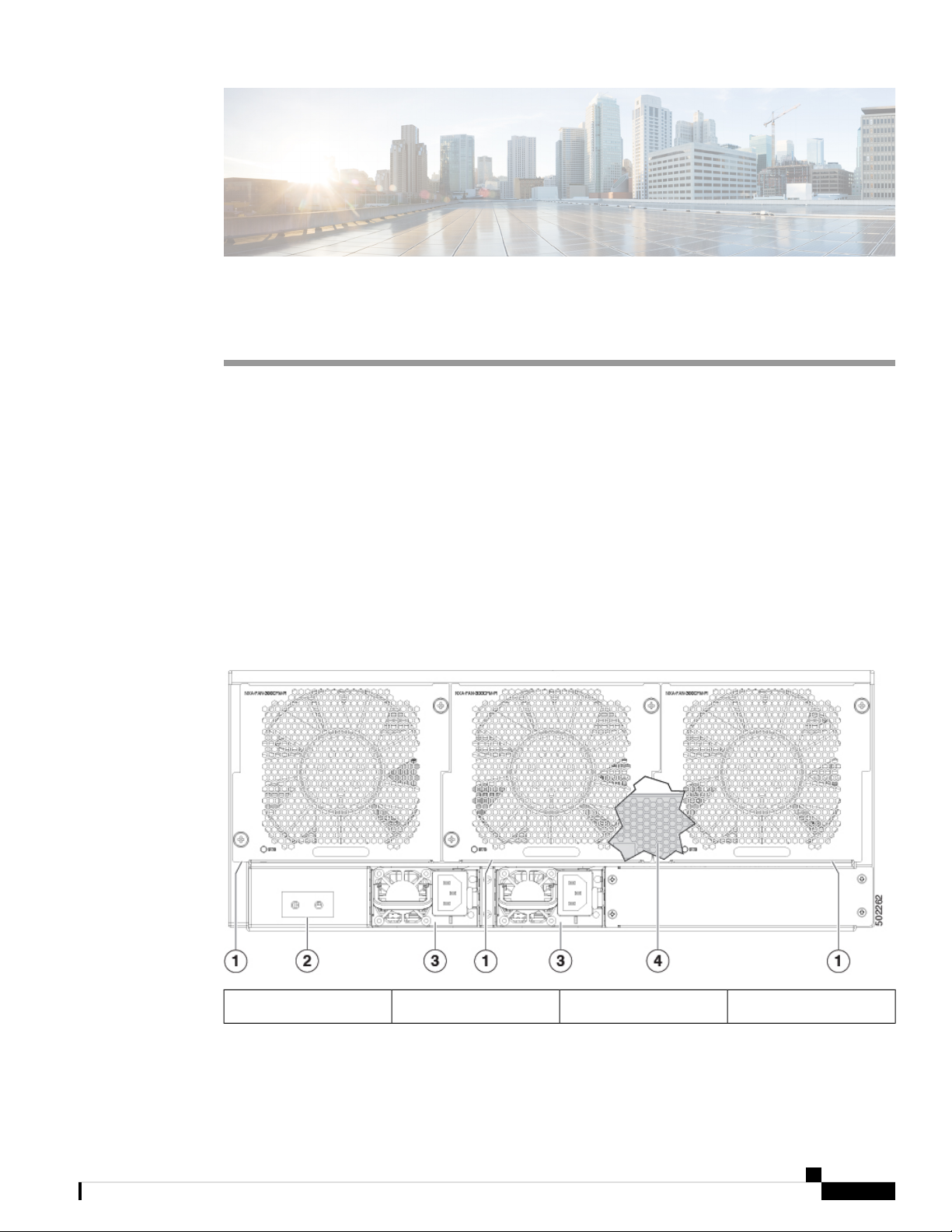
The following figure shows the fan-side chassis features that you use when installing the chassis or replacing
its modules.
Figure 1: Fan-Side View of the Cisco Nexus 3408-S Chassis
Grounding pad2Fan modules (3)1
Cisco Nexus 3400-S Hardware Installation Guide
1
Overview of the Cisco Nexus 3408-S Switch
Overview
4Power supply3
Cisco Nexus
NXB-CPU-FRU central
processing unit (CPU) that
is located inside the
chassis, behind the fan
modules.
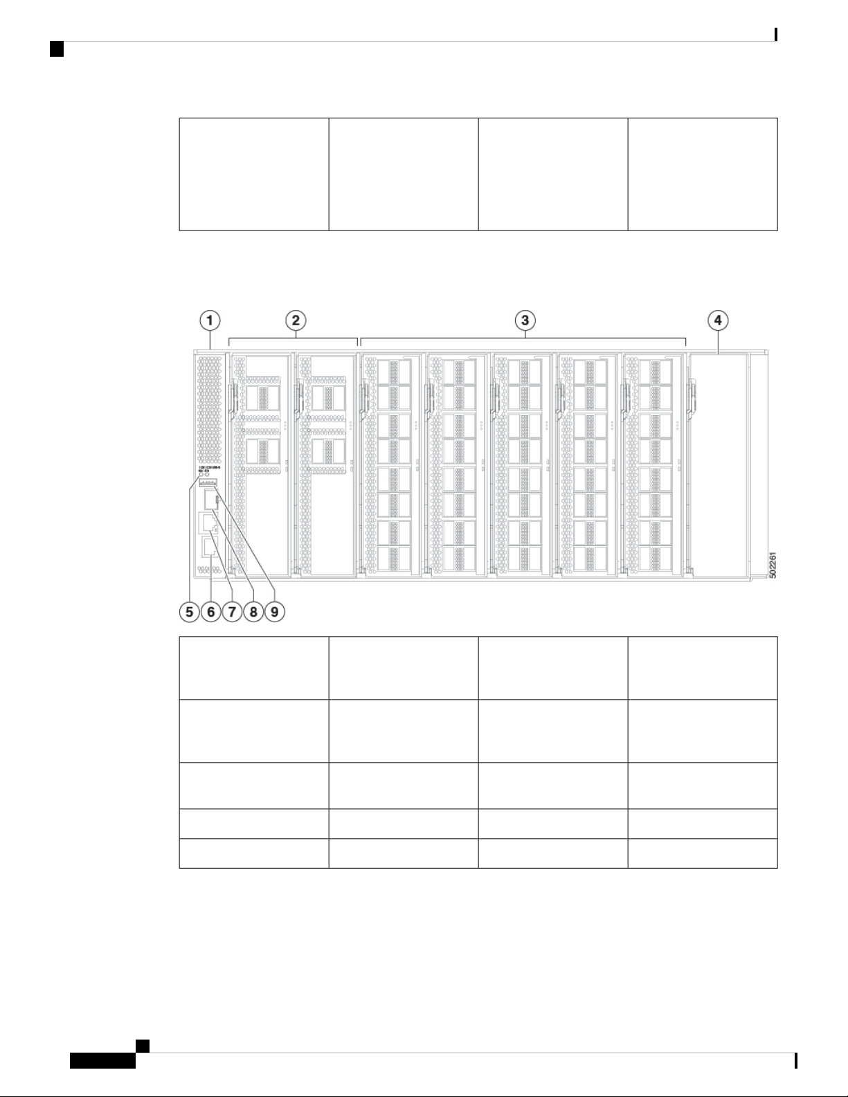
The following figure shows the port-side chassis features that you use when installing the chassis or replacing
its modules.
Figure 2: Port-Side View of the Cisco Nexus 3408-S Chassis
1
2Cisco Nexus 3408-S
modular chassis
Cisco Nexus NXM-X4D
line-card expansion
module (LEM) (up to 8)
3
4Cisco Nexus NXM-X16C
line-card expansion
Expansion module blank
(NXA-XBLANK)
module (LEM) (up to 8)
5
Management port (RJ-45)6Beacon (BCN) and Status
(STS) LEDs
Management port (SFP)8Console port (RS-232)7
USB port (1)9
The following figure shows the side chassis features that you use when installing the chassis.
Cisco Nexus 3400-S Hardware Installation Guide
2

Overview
Overview of the Cisco Nexus 3408-S Switch
Figure 3: Side View of the Cisco Nexus 3408-S Chassis
1
Screw holes for mounting
brackets
Cisco Nexus 3400-S Hardware Installation Guide
3

Overview of the Cisco Nexus 3408-S Switch
Overview
Cisco Nexus 3400-S Hardware Installation Guide
4

Preparing the Site
• Temperature Requirement, on page 5
• Humidity Requirement, on page 5
• Altitude Requirements, on page 5
• Dust and Contaminants, on page 5
Temperature Requirement
This switch is rated to operate at 32 to 104°F (0 to 40°C). It can be stored at -40 to 158°F (-40 to 70°C).
Humidity Requirement
This switch is rated to operate at 8- to 80-percent relative humidity with 10-percent gradation per hour. It can
be stored in an environment that has 5- to 95-percent relative humidity.
Buildings cooled with air conditioning during warm months and warmed during cold months usually maintain
an acceptable level of humidity. However, if the site is unusually humid, use a dehumidifier to maintain the
required humidity level.
CHAPTER 2
Altitude Requirements
High-altitude (low-pressure) conditions outside of 0 to 10,000 feet (0 to 3050 m) can reduce the cooling
efficiency and cause electrical problems.
Dust and Contaminants
To prevent contaminant buildup and increased internal chassis temperatures, make sure that the operating
environment is as clean as possible and free of dust and other contaminants. Do not permit smoking, food, or
drinks near the switch.
Cisco Nexus 3400-S Hardware Installation Guide
5

Dust and Contaminants
Preparing the Site
Cisco Nexus 3400-S Hardware Installation Guide
6

Safety
CHAPTER 3
Installing the Chassis
• Safety, on page 7
• Preparing to Install the Chassis, on page 8
• Unpacking and Inspecting the Chassis, on page 9
• Installing a 4 (RU) Chassis in a Four-Post Rack, on page 10
• Grounding the Chassis, on page 14
• Starting the Switch, on page 16
Before you install, operate, or service the switch, see the Regulatory, Compliance, and Safety Information for
the Cisco Nexus 3000 and 9000 Series for important Safety Information.
Warning
Warning
Warning
Statement 1071—Warning Definition
IMPORTANT SAFETY INSTRUCTIONS
This warning symbol means danger. You are in a situation that could cause bodily injury. Before you work
on any equipment, be aware of the hazards involved with electrical circuitry and be familiar with standard
practices for preventing accidents. Use the statement number provided at the end of each warning to locate
its translation in the translated safety warnings that accompanied this device.
SAVE THESE INSTRUCTIONS
Statement 1017—Restricted Area
This unit is intended for installation in restricted access areas. A restricted access area can be accessed by
skilled, instructed or qualified personnel.
Statement 1030—Equipment Installation
Only trained and qualified personnel should be allowed to install, replace, or service this equipment.
Cisco Nexus 3400-S Hardware Installation Guide
7
Preparing to Install the Chassis
Preparing to Install the Chassis
Before you can install the switch, you must verify the following:
• The installation site meets the following requirements as stated in Chapter 2:
• Environmental requirements for temperature, humidity, altitude, and air particulates.
• Cabinet or rack is installed and meets the requirements for the switch.
Note
Jumper power cords are available for use in a cabinet.
• The rack is positioned so that you can install the switch with its cold air intakes positioned in a cold
aisle.
If the fan and power supply modules are burgundy or red colored, you must install the chassis with
its port side in a cold aisle. If the modules are blue colored, you must be able install the chassis with
the fan modules in a cold aisle.
Installing the Chassis
• Earth ground connection is close to the switch. You must be able to easily connect the switch directly
to an earth ground or indirectly through a grounded rack.
Warning
High leakage current. Earth connection essential before connecting to power
supply.
• Site power meets the switch requirements. If you are using n+n redundancy, you must have two
power sources within reach of the switch when it is installed in the cabinet or rack.
If available, you can use an uninterruptible power supply (UPS) to protect against power failures.
Caution
Avoid UPS types that use ferroresonant technology. These UPS types can become
unstable with systems such as the Cisco Nexus 3000 Series switches. These
switches can have substantial current draw fluctuations because of fluctuating
data traffic patterns.
Ensure that circuits are sized according to local and national codes. For North America, the power
supply requires a 15-A or 20-A circuit.
Caution
To prevent loss of input power, ensure the total maximum loads on the circuits
supplying power to the switch are within the current ratings for the wiring and
breakers.
• There is adequate clearance around the rack to install the switch and to allow for unimpeded airflow.
• You have the following equipment in addition to the switch and the kits shipped with the switch:
Cisco Nexus 3400-S Hardware Installation Guide
8
Installing the Chassis
Unpacking and Inspecting the Chassis
• Eight customer-supplied 12-24 or 10-32 screws (required for attaching slider rails and mounting
bracket to the mounting rails)
• Number 1 and number 2 Phillips screwdrivers with torque capability
• 3/16-inch flat-blade screwdriver
• Tape measure and level
• ESD wrist strap or other grounding device (wrist strap can be found in the accessory kit)
• Antistatic surface large enough to place the switch
• Grounding cable (6 AWG recommended), sized according to local and national installation
requirements; the required length depends on the proximity of the switch to proper grounding
facilities
• Crimping tool large enough to accommodate the girth of the grounding lug
• Wire stripping tool
Unpacking and Inspecting the Chassis
Caution
Step 1 Compare the shipment to the equipment list provided by your customer service representative and verify that you have
received all items.
Step 2 Check for damage and report any discrepancies or damage to your customer service representative. Have the following
information ready:
When handling switch components, such as fan or power supply modules, wear a grounded ESD strap and
handle the modules by their carrier edges only. To ground the ESD strap, make sure that it is attached to an
earth ground, a grounded chassis, or a grounded rack.
Tip
Keep the shipping container in case the chassis requires shipping in the future.
Note
The switch is thoroughly inspected before shipment. If any damage occurred during transportation or any
items are missing, contact your customer service representative immediately.
To inspect the switch, follow these steps:
• Invoice number of shipper (see the packing slip)
• Model and serial number of the damaged unit
• Description of damage
Cisco Nexus 3400-S Hardware Installation Guide
9

Installing the Chassis
Installing a 4 (RU) Chassis in a Four-Post Rack
• Effect of damage on the installation
• Photos of the damaged shipping containers and damaged product
Step 3 For duel direction airflow switches, check to be sure that all of the fan and power supply modules have the same airflow
direction.
• Port-side intake airflow direction indicated with burgundy coloring
• Port-side exhaust airflow direction indicated with blue coloring
Installing a 4 (RU) Chassis in a Four-Post Rack
This section describes the rack installation for the Cisco Nexus 3408-S platform switch into a four-post rack.
Before moving or lifting the chassis, follow these guidelines:
• Ensure that all cables are disconnected from the switch.
• Ensure that there is adequate space around the switch for servicing and airflow.
• Never attempt to lift an object that might be too heavy for you to lift by yourself.
• Ensure that you have solid footing and that the weight of the switch is evenly distributed between your
feet.
• Lift the switch slowly, keeping your back straight. Lift with your legs, not with your back. Bend at the
knees, not at the waist.
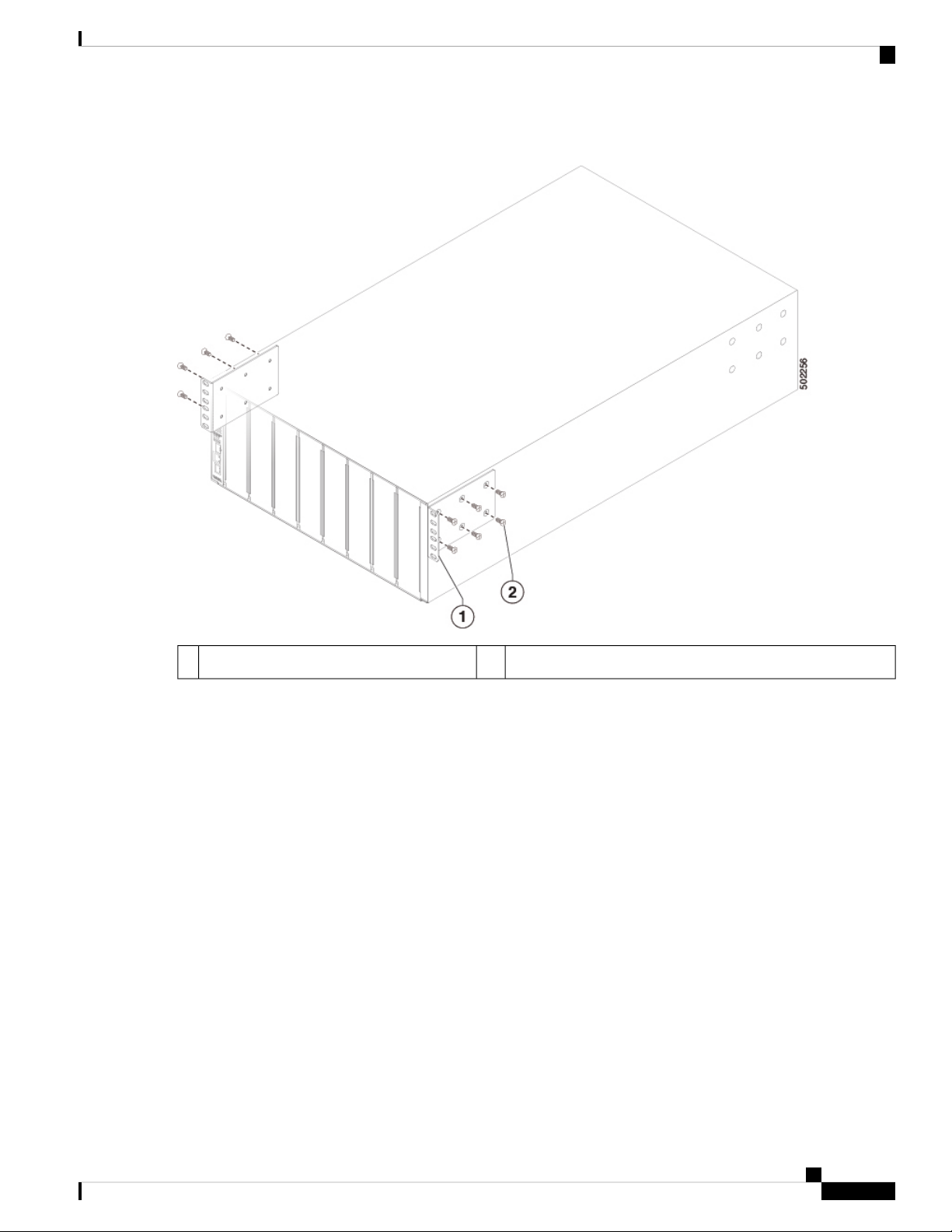
Step 1 Attach two front-mount brackets to the sides of the chassis as follows:
a) Align the two holes in one side of a front-mount bracket to the holes on the left or right side of the chassis as shown
in the following figure.
Cisco Nexus 3400-S Hardware Installation Guide
10
Installing the Chassis
Figure 4: Aligning and attaching Front-Mount Brackets to the Chassis
Installing a 4 (RU) Chassis in a Four-Post Rack
M4 x 6 mm screws2Front rack-mount bracket1
b) Use M4 x 6 mm screws to attach the bracket to the chassis and tighten each screw to 12 in-lb (1.36 N·m) of torque.
c) Repeat Steps 1a and 1b to attach the other front-mount bracket to the other side of the chassis.
Step 2 Align the bottom-support rails so that they form a shelf for the chassis.
Note
The bottom-support rails are identical and interchangeable. Each can be used for either the right, or the left side
of the rack.
a) Rotate one of the rails as shown in the following figure.
Cisco Nexus 3400-S Hardware Installation Guide
11
 Loading...