

Page 1

© 2013 Cisco and/or its affiliates. All rights reserved. This document is Cisco Public Information. Page 1 of 39
Cisco Nexus 1100 Series
Virtual Services Appliances
Deployment Guide Version 1.0
June 2013
Deployment Guide
Page 2

© 2013 Cisco and/or its affiliates. All rights reserved. This document is Cisco Public Information. Page 2 of 39
Overview ................................................................................................................................................................... 4
Audience ................................................................................................................................................................... 4
Introduction .............................................................................................................................................................. 4
Cisco Nexus 1000V Series Switches ...................................................................................................................... 4
Cisco Nexus 1100 Series VSAs: Cisco Nexus 1110-S and 1110-X Models ......................................................... 5
Cisco Nexus 1110-S Physical Components .......................................................................................................... 5
Cisco Nexus 1110-X Physical Components .......................................................................................................... 5
Virtual Service Blades ............................................................................................................................................. 5
Sample Cisco Nexus 1110-S Configurations ........................................................................................................ 6
Sample Cisco Nexus 1110-X Configurations ........................................................................................................ 6
Cisco Nexus 1100 Series High Availability ............................................................................................................ 7
Network Connectivity .............................................................................................................................................. 8
Management VLAN ............................................................................................................................................... 8
Control VLAN ........................................................................................................................................................ 8
Network Connectivity Options ................................................................................................................................ 9
Network Connection Option 1 ............................................................................................................................... 9
Network Connection Option 2 ............................................................................................................................. 10
Network Connection Option 3 ............................................................................................................................. 12
Network Connection Option 4 ............................................................................................................................. 13
Network Connection Option 5 (Flexible Network) ............................................................................................... 15
Deployment Considerations ................................................................................................................................. 17
Topology Examples ............................................................................................................................................... 18
Uplink Type 1 ...................................................................................................................................................... 18
Cisco Nexus 5000-1 and Nexus 5000-2 Configuration ................................................................................... 18
Uplink Type 2 ...................................................................................................................................................... 19
Cisco Nexus 5000-1 and Nexus 5000-2 Configuration ................................................................................... 19
Uplink Type 3 ...................................................................................................................................................... 20
Cisco Nexus 5000-1 and Nexus 5000-2 Configuration ................................................................................... 21
Uplink Type 4 ...................................................................................................................................................... 21
Cisco Nexus 5000-1 and Nexus 5000-2 Configuration ................................................................................... 22
Uplink Type 5 ...................................................................................................................................................... 22
Cisco Nexus 5000-1 and Nexus 5000-2 Configuration ................................................................................... 23
Deploying the Cisco Nexus 1000V Series VSM on the Cisco Nexus 1100 Series ............................................ 24
VSM High Availablity ............................................................................................................................................. 24
Cisco Nexus 1000V Series Backup and Restore Procedures ............................................................................ 24
Backup Procedure .............................................................................................................................................. 24
Restore Procedure .............................................................................................................................................. 24
Deploying the Cisco Nexus 1100 Series Across Data Centers .......................................................................... 25
Appendix: Quick Configuration Guide ................................................................................................................. 26
Configure the Upstream Cisco Nexus 5000 Series Switch ................................................................................. 27
Cisco Nexus 1100 Series LOM Ports Connected to Cisco Nexus 2248 ......................................................... 27
Cisco Nexus 1100 Series Control, Packet, and Data Gigabit Ethernet Ports Connected to Cisco Nexus 2248
....................................................................................................................................................................... 27
Set Up the Primary Cisco Nexus 1100 Series VSA ............................................................................................ 29
Set Up the Secondary Cisco Nexus 1100 Series VSA ........................................................................................ 31
Verify the Cisco Nexus 1100 Series Setup ......................................................................................................... 32
Page 3

© 2013 Cisco and/or its affiliates. All rights reserved. This document is Cisco Public Information. Page 3 of 39
Instantiate the Cisco Nexus 1000V Series VSM ................................................................................................. 32
Verify the Cisco Nexus 1000V Series VSB ......................................................................................................... 34
Complete the Cisco Nexus 1000V Series Installation ......................................................................................... 35
For More Information ............................................................................................................................................. 38
Cisco Nexus 1100 Series Technical Documentation .......................................................................................... 38
Page 4
© 2013 Cisco and/or its affiliates. All rights reserved. This document is Cisco Public Information. Page 4 of 39
Overview
This document provides design guidelines for deploying Cisco Nexus® 1100 Series Virtual Services Appliances
(VSAs). The Cisco Nexus 1110-S and 1110-X VSAs are the first appliances in the Cisco Nexus 1100 Series.
For detailed feature-level configuration documentation, please refer to the respective Cisco® product configuration
guides located at http://www.cisco.com/go/1100. Links to additional information can be found in the “For More
Information” section of this document.
Audience
This document is intended for network architects, network engineers, virtualization administrators, and server
administrators interested in understanding and deploying the Cisco Nexus 1000V Series Swtiches utilizing the
Cisco Nexus 1100 Series in a Cisco data center environment.
Introduction
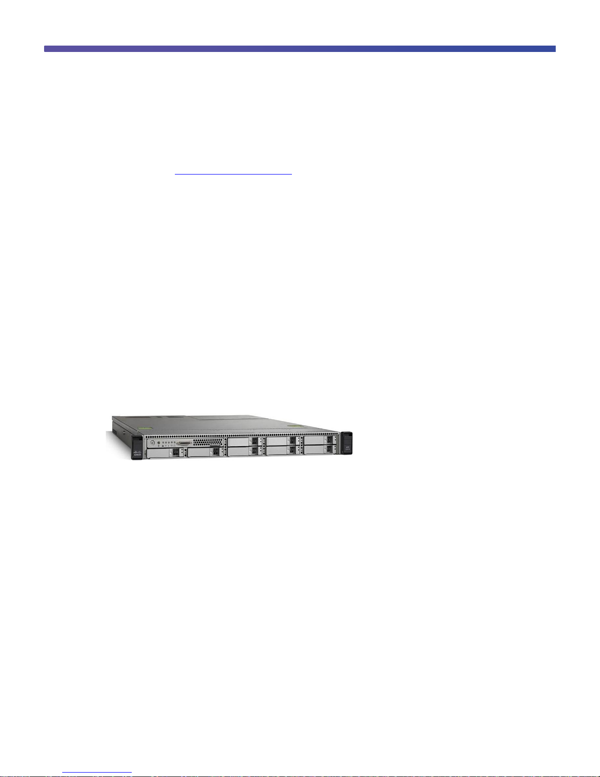
The Cisco Nexus 1100 Series VSAs (Figure 1) are members of the Cisco Nexus 1000V Series Switches portfolio.
They host the Cisco Nexus 1000V Series Virtual Supervisor Modules (VSMs) and provide support for Cisco virtual
service blades (VSBs) to offer a more comprehensive solution for virtual access switching. Because the Cisco
Nexus VSAs provide dedicated hardware for the VSM, they makes virtual access switch deployment easier for the
network administrator. Support for additional VSBs such as the Cisco Virtual Security Gateway (VSG), Cisco
Prime™ Network Analysis Module (NAM), and Cisco Data Center Network Mangager (DCNM) makes the Cisco
Nexus VSAs crucial components of a virtual access switch solution.
Figure 1. Cisco Nexus 1110-S and 1110-X Virtual Services Appliances
Cisco Nexus 1000V Series Switches
Cisco Nexus 1000V Series Switches are virtual machine access switches. They are intelligent switches designed
for hypervisor environments running the Cisco NX-OS Software operating system. Operating inside the hypervisor,
the Cisco Nexus 1000V Series supports server virtualization technology to provide:
●
Policy-based virtual machine connectivity
●
Mobile virtual machine security and network policy
●
Nondisruptive operational model for server virtualization and networking teams
When server virtualization is deployed in the data center, virtual servers typically are not managed the same way
as physical servers. Server virtualization is treated as a special deployment, leading to longer deployment times,
with a greater degree of coordination needed among server, network, storage, and security administrators. With
the Cisco Nexus 1000V Series, you can have a consistent networking feature set and provisioning process all the
way from the virtual machine access layer to the core of the data center network infrastructure. Virtual servers can
now use the same network configuration, security policy, diagnostic tools, and operation models as their physical
server counterparts attached to dedicated physical network ports. Virtualization administrators can access a
predefined network policy that follows mobile virtual machines to help ensure proper connectivity, saving valuable
time to allow you to focus on virtual machine administration. This comprehensive set of capabilities helps you
deploy server virtualization and achieve its benefits more quickly.
Page 5

© 2013 Cisco and/or its affiliates. All rights reserved. This document is Cisco Public Information. Page 5 of 39
Cisco Nexus 1100 Series VSAs: Cisco Nexus 1110-S and 1110-X Models
The Cisco Nexus 1110-S and 1110-X VSAs each offer a physical platform for deploying and managing the Cisco
Nexus 1000V VSMs and other virtual services. The platform consists of the physical server coupled with the Cisco
Nexus VSA Manager software, which houses multiple Cisco VSBs.
Cisco Nexus 1110-S Physical Components
The physical components of the Cisco Nexus 1110-S are based on the Cisco UCS® C220 M3 Rack Server
containing:
●
Two 2.00-GHz Intel Xeon E5-2650 processors, each with eight cores
●
Four 8-GB DDR3 1600-MHz RDIMMs
●
Two 1-terabyte (TB) SATA HDDs
●
One Intel Quad Gigabit Ethernet adapter and two 1 Gigabit Ethernet LAN-on-motherboard (LOM) interfaces
●
One serial port
●
One rail kit
●
One RAID controller using RAID 1
Cisco Nexus 1110-X Physical Components
The physical components of the Cisco Nexus 1110-X are based on the Cisco UCS C200 M2 High-Density Rack
Server physical appliance containing:
●
Two 2.00-GHz Intel Xeon E5-2650 processors, each with eight cores
●
Eight 8-GB DDR3 1600-MHz RDIMMs
●
Four 1-TB SATA HDDs
●
One Intel Quad Gigabit Ethernet adapter and two 1 Gigabit Ethernet LOM interfaces
●
One Cisco UCS Virtual Interface Card (VIC) 1225 dual-port 10-Gbps Enhanced Small Form-Factor
Pluggable (SFP+) converged network adapter (CNA)*
●
One serial port
●
One rail kit
●
One RAID controller using RAID 10
*
10-Gbps networking will be enabled in a later Cisco NX-OS software release; the Cisco Nexus 1110-X ships with
the 10-Gbps VIC.
Virtual Service Blades
A VSB provides expansion capabilities so that new services can be added to the Cisco Nexus 1100 Series in the
future. The Cisco Nexus VSA Manager enables customers to install, configure, and manage a variety of VSBs.
The Cisco Nexus 1110-S and 1110-X currently support the following VSBs:
●
Cisco Nexus 1000V Series VSM
●
Cisco VSG for Nexus 1000V Series Switch
●
Cisco Prime NAM
●
Cisco DCNM
●
Imperva SecureSphere Web Application Firewall
Page 6

© 2013 Cisco and/or its affiliates. All rights reserved. This document is Cisco Public Information. Page 6 of 39
Cisco VSM
Cisco VSG
Cisco NAM
Cisco DCNM
Total Weight
Cisco Nexus 1110-S
1
1
2
2
<=6
Cisco Nexus 1110-X
1
1
2
2
<=10
VSB deployments support the ISO and OVA image formats. OVA support allows users to deploy a VSB from a
VMware virtual machine file format. A common use case is migration of the VSM as a virtual machine to the Cisco
Nexus 1100 Series.
The Cisco Nexus 1110-S can host up to 6 VSBs, and the Cisco Nexus 1110-X can host up to 10 VSBs. These
VSBs can be any combination of the VSBs supported. Figure 2 shows an example of a configuration.
Figure 2. Cisco Nexus 1100 Series with Four VSBs: Cisco VSMs, VSGs, NAM, and DCNM
Table 1 shows the weight of each virtual service in the Cisco Nexus 1110-S and 1110-X platforms.
Table 1. Weighting Matrix to Determine Maximum Capacity of VSBs on Cisco Nexus 1100 Series VSAs
Sample Cisco Nexus 1110-S Configurations
●
Six Cisco VSMs
●
Six Cisco VSGs
●
Three Cisco VSMs and three Cisco VSGs
●
One Cisco VSM, one Cisco VSG, one Cisco NAM, and one Cisco DCNM
Sample Cisco Nexus 1110-X Configurations
●
Ten Cisco VSMs
●
Ten Cisco VSGs
●
Five Cisco VSMs and five Cisco VSGs
●
Three Cisco VSMs, three Cisco VSGs, one Cisco NAM, and one Cisco DCNM
Page 7
© 2013 Cisco and/or its affiliates. All rights reserved. This document is Cisco Public Information. Page 7 of 39
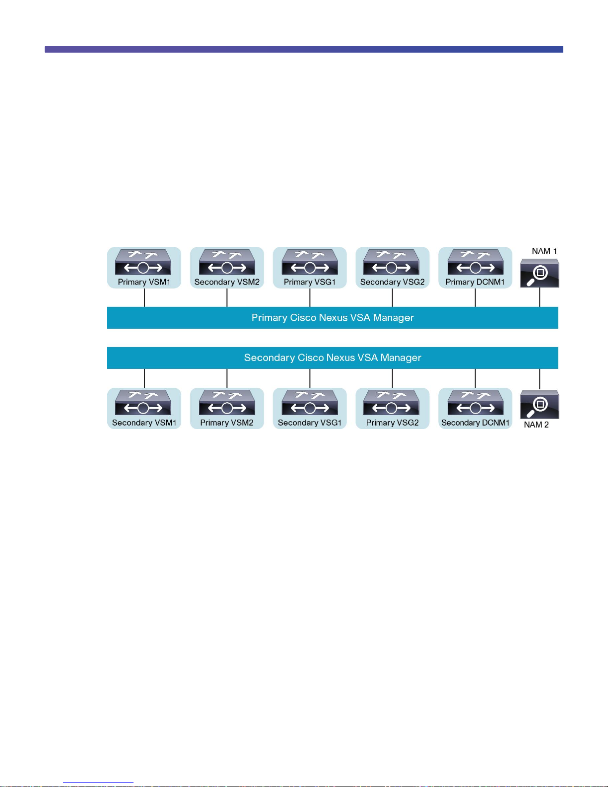
Cisco Nexus 1100 Series High Availability
To achieve high availability, you should deploy redundant Cisco Nexus 1100 Series appliances, with one Cisco
Nexus 1100 Series VSA as the primary device, and the second Cisco Nexus 1100 Series VSA as the secondary
device. The two appliances run in an active-standby configuration to offer high availability for both management
and VSB deployments. Certain virtual services, such as Cisco NAMs, do not support high availability. Please refer
to the documentation for the particular Cisco VSB to determine whether the VSB supports high availability. Figure 3
shows the built-in high availability for both the Cisco VSMs and VSGs.
Figure 3. Cisco Nexus 1100 Series High-Availability Pair
If one Cisco Nexus 1100 Series VSA fails, management automatically fails over to the other Cisco Nexus 1100
Series VSA without disruption of traffic or operations. For two Cisco Nexus 1100 Series appliances to form a highavailability pair, the control VLAN and domain ID of both Cisco Nexus 1100 Series appliances must match.
Another high-availability feature built into the Cisco Nexus 1100 Series is the capability of the Cisco Nexus VSA
Manager to automatically distribute the placement of the active VSBs across the two appliances. This feature helps
balance the distribution of traffic and reduce the size of the potential fault domain.
The pairing of the Cisco Nexus 1100 Series appliances must match the hardware platform. A Cisco Nexus 1100
Series VSA must be paired with another identical Cisco Nexus 1100 Series platform; mixing of platforms is not
supported, such as mixing a Cisco Nexus 1110-S with a Cisco Nexus 1110-X.
Not every VSB is the primary module on the primary Cisco Nexus 1100 Series VSA. With connectivity between the
primary and secondary Cisco Nexus 1100 Series VSA, access through a serial connection to any virtual service is
maintained. When one Cisco Nexus 1100 Series VSA fails, the remaining Cisco Nexus 1100 Series VSA becomes
active, and all virtual services in the standby state on that Cisco Nexus 1100 Series VSA become active
automatically.
Page 8

© 2013 Cisco and/or its affiliates. All rights reserved. This document is Cisco Public Information. Page 8 of 39
A virtual service can be removed completely from both redundant Cisco Nexus 1100 Series appliances, or from
only one. If one of the redundant pair of virtual services becomes unusable, it can be removed from the Cisco
Nexus 1100 Series platform on which it resides. This approach facilitates recovery by preserving the remaining
virtual service in the pair. Use of this service may be needed if a new instance of the service must be provisioned.
Network Connectivity
The Cisco Nexus 1110-S has six 1 Gigabit Ethernet interfaces available for network connectivity: two 1 Gigabit
Ethernet LOM interfaces and four 1 Gigabit Ethernet interfaces, available through a PCI card (Figure 4). In additon,
the Cisco Nexus 1110-X has two 10 Gigabit Ethernet interfaces that will be enabled in a later software release.
These interfaces are not shown in Figure 4.
Figure 4. Connections on Cisco Nexus 1100 Series VSAs
Four types of traffic flow through these interfaces: management, control, packet, and VSB data traffic. The Cisco
Nexus 1100 Series is not in the data path of everyday virtual machine data traffic. However, when Cisco NAM or
VSG VSBs are deployed, data traffic from selected virtual machines will flow to the Cisco Nexus 1100 Series to be
processed by the respective network service. The decision to use or not use these other VSBs influences the
choice of network connectivity option used for connecting the Cisco Nexus 1100 Series to the network.
Management VLAN
The management VLAN is used for management of the Cisco Nexus 1100 Series VSA. When one of the four static
uplink options is used, the Cisco Nexus 1100 Series and its hosted VSBs share the same management VLAN. In a
static topology, the management VLAN on a VSB cannot be changed directly. Since the management VLAN is
inherited from the Cisco Nexus 1100 Series VSA, if you change the management VLAN for the Cisco Nexus 1100
Series, then the change is applied to both the Cisco Nexus 1100 Series VSA and all its hosted VSBs at the next
reload.
However, this constraint does not exist in flexible topology, and the management VLAN of a VSB can be different
from the Cisco Nexus 1100 Series host.
Control VLAN
The control VLAN is a Layer 2 interface used for communication between the redundant Cisco Nexus 1100 Series
appliances. This interface handles low-level control packets such as heartbeats as well as any configuration data
that needs to be exchanged between the Cisco Nexus 1100 Series appliances.
Page 9
© 2013 Cisco and/or its affiliates. All rights reserved. This document is Cisco Public Information. Page 9 of 39
Network Connectivity Options
The interfaces on the Cisco Nexus 1100 Series can be connected to the network in five ways. The choice of the
connectivity option, or uplink type, for the Cisco Nexus 1100 Series depends on the customer’s needs and
requirements. When the Cisco Nexus 1100 Series VSA is first initialized, the setup script requests some basic
configuration information, including selection of the network connectivity option. This section explains the five
uplink types (or network connectivity options) and discusses best practices for choosing the best option.
Network Connection Option 1
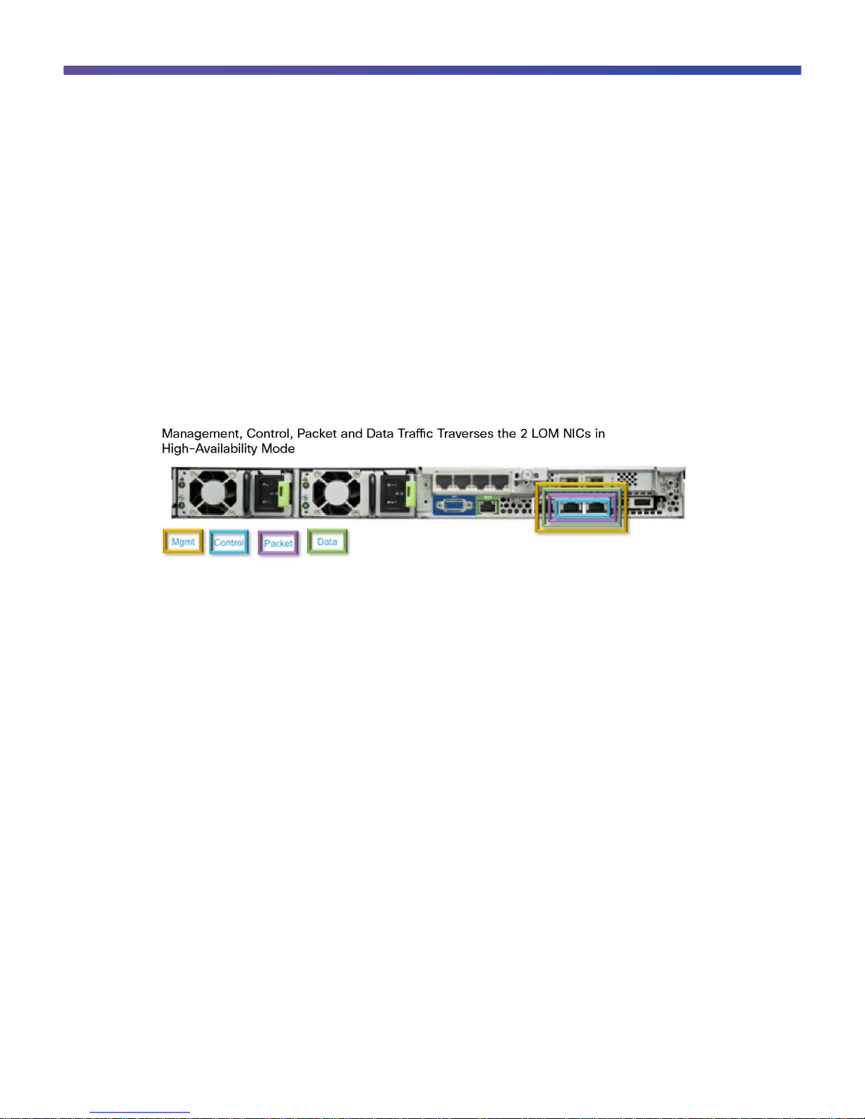
Option 1, the simplest way of connecting the Cisco Nexus 1100 Series to the network, uses the two LOM interfaces
to carry all traffic types: management, control, packet, and data. In this configuration, each uplink connects to two
different upstream switches to provide redundancy (Figure 5).
Figure 5. Network Connection Option 1
Option 1 is preferred in cases in which customers are not using a Cisco NAM and therefore have little or no data
traffic traversing the uplinks to the Cisco Nexus 1100 Series. This option is commonly used when the Cisco Nexus
1100 Series is used only for VSMs. The management, control, packet, and data traffic can all use different VLANs,
although this is not a requirement. This option is recommended for the simplest configuration and lowest risk of
misconfiguration (Figure 6).
Page 10

© 2013 Cisco and/or its affiliates. All rights reserved. This document is Cisco Public Information. Page 10 of 39
Figure 6. Option 1 Configuration
Note: The LOM ports are active-standby only and cannot be part of a PortChannel or virtual PortChannel (vPC).
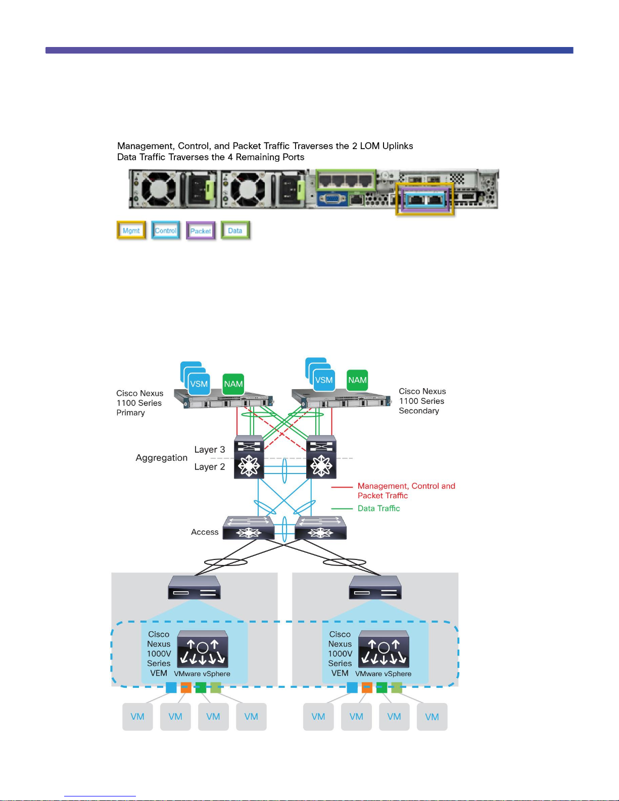
Network Connection Option 2
Option 2 uses the two LOM interfaces to carry management, control, and packet traffic. The other four interfaces
on the PCI card carry only data traffic. In this configuration, the two interfaces used for management, control, and
packet traffic should be connected to two separate upstream switches for redundancy. In addition, the four ports
used for data traffic should be split between two upstream switches for redundancy. Not all four interfaces are
required, and their use depends on bandwidth requirements. Use a minimum of two interfaces that are also
connected to two separate physical switches. In addition, if multichassis EtherChannel is available, that technology
is preferred, to provide additional bandwidth and redundancy (Figure 7).
Page 11
© 2013 Cisco and/or its affiliates. All rights reserved. This document is Cisco Public Information. Page 11 of 39
Figure 7. Network Connection Option 2
Option 2 is well suited for customers who are deploying a Cisco NAM in the Cisco Nexus 1100 Series. The
management, control, and packet traffic is kept physically separate from the data traffic, helping ensure that data
traffic does not divert cycles from the other traffic. Of the four available connectivity options, option 2 provides the
most dedicated bandwidth for Cisco NAM traffic and should be used by customers who want to increase the Cisco
NAM capabilities (Figure 8).
Figure 8. Option 2 Configuration
Page 12
© 2013 Cisco and/or its affiliates. All rights reserved. This document is Cisco Public Information. Page 12 of 39
Option 2 is well suited for customers who are deploying a NAM module in the Cisco Nexus 1100 Series VSA. The
management, control, and packet traffic is kept physically separate from the data traffic, helping ensure that data
traffic does not divert cycles from the other traffic. Out of the four available connectivity options, this option provides
the most dedicated bandwidth for NAM traffic and should be used by customers who want to take full advantage of
the NAM capabilities.
Note: The 4-port network interface card (NIC) adapter does support PortChannel and vPC capabilities and can
provide added bandwidth utilization and redundancy. The example here shows the use of a PortChannel, but a
vPC configuration would also be valid.
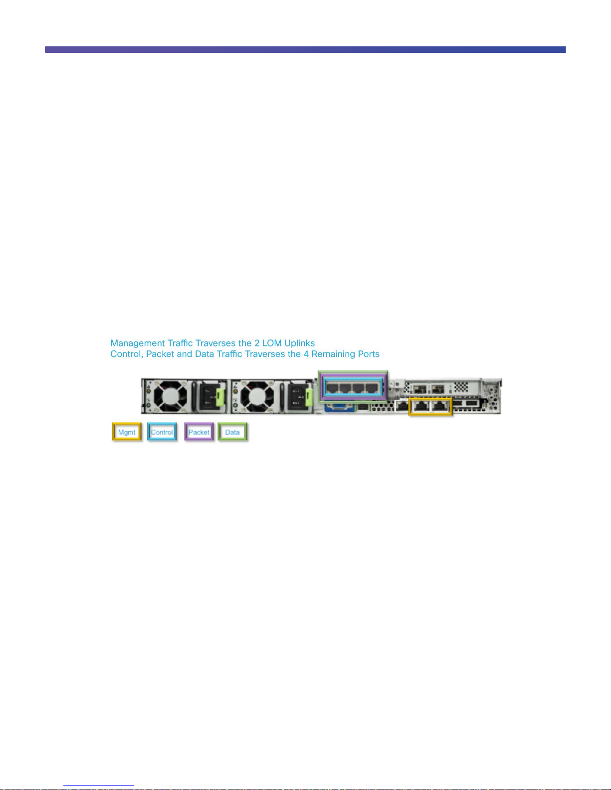
Network Connection Option 3
Option 3 uses the two LOM interfaces for management traffic only, and it uses the four interfaces on the PCI card
to carry control, packet, and data traffic. In this configuration, the two management interfaces should be connected
to two separate upstream switches for redundancy. In addition, the four ports used for control, packet, and data
traffic should be split between two upstream switches for redundancy (Figure 9).
Figure 9. Network Connection Option 3
Option 3 is well suited for customers who are deploying a Cisco NAM or VSG in the Cisco Nexus 1100 Series but
require a separate management network. Because there is little control and packet traffic, customers can still use
most of the bandwidth from the four 1 Gigabit Ethernet interfaces for Cisco NAM traffic. This option is
recommended for most deployments because it provides the flexibility to handle both currently supported and
future VSBs (Figure 10).
Page 13

© 2013 Cisco and/or its affiliates. All rights reserved. This document is Cisco Public Information. Page 13 of 39
Figure 10. Option 3 Configuration
Note: Physical connectivity does not change for this network option. As in the PortChannel configuration for
network option 2, a vPC configuration is also valid.
Network Connection Option 4
Option 4 uses the two LOM interfaces for management traffic, two of the four PCI interfaces for control and packet
traffic, and the other two PCI interfaces for data traffic. Each of these pairs of interfaces should be split between
two upstream switches for redundancy (Figure 11).
Page 14

© 2013 Cisco and/or its affiliates. All rights reserved. This document is Cisco Public Information. Page 14 of 39
Figure 11. Network Connection Option 4
Option 4 is well suited for customers who want to use the Cisco NAM but require separate data and control
networks. Separating the control from the data network helps ensure that Cisco NAM traffic does not divert cycles
from control traffic and therefore affect connectivity (Figure 12).
Figure 12. Option 4 Configuration
Page 15

© 2013 Cisco and/or its affiliates. All rights reserved. This document is Cisco Public Information. Page 15 of 39
Note: Since each type of traffic uses two physical interfaces, use of a vPC is recommended if possible.
Otherwise, a regular PortChannel configuration should be used, but the two physical links need to connect to a
single upstream switch.
Network Connection Option 5 (Flexible Network)
With the addition of the flexible network option, users can now more flexibly deploy their VSBs on the Cisco Nexus
1100 Series. With this option, you do not need to specify which ports allow which types of traffic (management,
control, or data traffic). One of the main advantages of this option is that you can define a VSB to use a particular
interface. This approach enables a more specific level of traffic engineering for security purposes. For example, a
VSM VSB for production can use an interface connected to the production network, and another VSM VSB can be
created for the DMZ, which uses another interface connected to the DMZ network. Figure 13 shows two of the
possible options with the flexible network traffic flow options.
Figure 13. Network Connection Option 5
Note: The options shown here are just two possible options; other options are possible that are a mix of the
combinations shown.
Another feature enhancement in the Cisco Nexus 1100 Series Version 4.2(1)SP1(4) release is the capability to
create a PortChannel with the LOM interfaces as well with the other four Gigabit Ethernet interfaces. This
enhancement can simplify the configuration for network connectivity, as shown in Figure 14.
Page 16

© 2013 Cisco and/or its affiliates. All rights reserved. This document is Cisco Public Information. Page 16 of 39
Figure 14. Option 5 Configuration
Another configuration option is dedication of a single interface to a particular VSB. the Cisco Nexus 1100 Series
has six physical interfaces but one of the interfaces needs to be used for Cisco Nexus 1100 Series communication,
so five interfaces are available to host dedicated VSBs. Figure 15 shows a possible connectivity configuration for
this option.
Page 17

© 2013 Cisco and/or its affiliates. All rights reserved. This document is Cisco Public Information. Page 17 of 39
Figure 15. Option 5 Connectivity
Note: With support of up to 10 VSBs on the Cisco Nexus 1110-X, some of the interfaces may have multiple
VSBs sharing the same interface. Also, VSBs that do not support high availability (Cisco NAM and DCNM VSBs,
for example) will not have redundancy if there is no NIC redundancy from the perspective of the Cisco Nexus 1110S or 1110-X.
This flexible option is an excellent option for users who want more control over the design of the VSBs for
optimized flexibility and redundancy.
Deployment Considerations
The Cisco Nexus 1100 Series offers many deployment benefits. First, because a Cisco Nexus 1100 Series VSA is
an appliance owned and operated by the network team, deployment no longer depends on collaboration by
network, storage, and virtualization operations teams. Instead, the Cisco Nexus 1100 Series can be installed and
deployed in the same way as any networking device.
Another benefit is flexibility as to where the Cisco Nexus 1100 Series is inserted into the network. The previous
section discussed the five options for connecting the Cisco Nexus 1100 Series to the network. These methods can
be used in various areas of the network. Typically, Cisco Nexus 1100 Series appliances are deployed within a
central management domain. Often, this location is the location in which other network appliances, such as Cisco
Wide Area Application Services (WAAS) and NAM appliances, are deployed.
Typically, the Cisco Nexus 1100 Series is best deployed at the aggregation layer of the network so that it can host
a larger set of servers. Because the architecture of the Cisco Nexus 5000 Series Switches and Cisco Nexus 2000
Series Fabric Extenders supports up to 1152 servers, deploying the Cisco Nexus 1100 Series on the Cisco Nexus
2000 Series provides a large pool of servers supported on a single point of management for those servers, while
also treating the Cisco Nexus 1100 Series VSA as a virtual switch connected to the Cisco Nexus 5000 and 2000
Series architecture.
Because the Cisco Nexus 1100 Series uses 1 Gigabit Ethernet interfaces to connect to the network, a fabric
extender provides an optimal connectivity solution. Connecting a Cisco Nexus 1100 Series VSA to a Cisco Nexus
Family switch or fabric extender module helps simplify deployment by running the same operating system, Cisco
NX-OS, on both devices.
Page 18

© 2013 Cisco and/or its affiliates. All rights reserved. This document is Cisco Public Information. Page 18 of 39
Topology Examples
The following topology examples use the premise of connecting the Cisco Nexus 1100 Series directly to Cisco
Nexus 2000 Series Fabric Extenders on a Cisco Nexus 5000 Series parent switch. The vPC technology on the
Cisco Nexus 5000 and 7000 Series Switches (or any other switch that supports multichassis EtherChannel
technology) can be used to increase bandwidth utilization on uplink types that support Link Aggregation Control
Protocol (LACP) PortChannels.
This section discusses the four uplink types in the context of connection to upstream switches that use Cisco
Nexus 2000 Series Fabric Extenders. Note that this discussion can also apply when you connect to other upstream
switches.
Uplink Type 1
In the uplink type 1 topology (Figure 16), all traffic (management, control, and VSB data traffic) is switched out at
an effective bandwidth of 1 Gbps. Both ports on the Cisco Nexus 1100 Series, Ethernet interfaces 1 and 2, are
teamed to form an active-standby pair. This uplink type is simplistic and does not require any PortChannel or LACP
configuration on the upstream switches.
Figure 16. Uplink Type 1
The upstream Cisco Nexus 5000 Series configuration would look similar to the following for the access ports to
which the Cisco Nexus 1100 Series connects.
Cisco Nexus 5000-1 and Nexus 5000-2 Configuration
interface ethernet 101/1/1-2
switchport mode trunk !-- multiple vlans trunked across link
switchport trunk allowed vlan 170,250-251 !—only allow mgmt, control and data
vlans
spanning-tree port type edge trunk !-- enable portfast edge
Page 19

© 2013 Cisco and/or its affiliates. All rights reserved. This document is Cisco Public Information. Page 19 of 39
Uplink Type 2
In the uplink type 2 topology (Figure 17), management and control traffic is switched out of the first two Ethernet
interfaces. Ethernet interfaces 1 and 2 are forwarding as an active-standby pair, just as in uplink type 1. However,
VSB data traffic is carried out of Ethernet interfaces 3 through 6. If vPC (or similar clustering) is used on the
upstream switches, the effective combined bandwidth is 5 Gbps for each Cisco Nexus 1100 Series VSA. This
uplink type is well suited when more non-VSM VSBs, such as Cisco NAM or VSG VSBs, are used, because there
is more bandwidth for the VSB data traffic to use.
Figure 17. Uplink Type 2
Here, LACP PortChannel technology is used on the upstream switches to give each Cisco Nexus 1100 Series VSA
its own PortChannel across the two Cisco Nexus 5000 Series Switches. The configuration upstream would look
similar to the following.
Cisco Nexus 5000-1 and Nexus 5000-2 Configuration
interface ethernet 101/1/1, 101/1/2
switchport mode trunk !-- multiple vlans trunked across link
switchport trunk allowed vlan 170,250 !—- only allow mgmt and control vlans
spanning-tree port type edge trunk !-- enable portfast edge
interface ethernet 101/1/3, 101/1/4
switchport mode trunk !-- multiple vlans trunked across link
switchport trunk allowed vlan 251 !-- only allow data vlan(s)
spanning-tree port type edge trunk !-- enable portfast edge
channel-group 1110 mode active !-- add interface to port-channel
interface port-channel 1110 !-- this is a unique vpc for N1110 Primary
Page 20

© 2013 Cisco and/or its affiliates. All rights reserved. This document is Cisco Public Information. Page 20 of 39
vpc 1110
interface ethernet 101/1/5, 101/1/6
switchport mode trunk !-- multiple vlans trunked across link
switchport trunk allowed vlan 251 !-- only allow data vlan(s)
spanning-tree port type edge trunk !-- enable portfast edge
channel-group 1011 mode active !-- add interface to port-channel
interface port-channel 1011 !-- this is a unique vpc for N1110 Secondary
vpc 1011
Uplink Type 3
Uplink type 3 (Figure 18) is physically identical to uplink type 2 because it uses all the Ethernet interfaces available.
The difference is in the way that the traffic is carried across these interfaces. In this topology, management traffic is
switched out of the first two Ethernet interfaces. Ethernet interfaces 1 and 2 are forwarding as an active-standby
pair, just as in the other uplink types. However, both control and VSB data traffic is carried out of Ethernet
interfaces 3 through 6. If vPC (or similar clustering) is used on the upstream switches, the effective combined
bandwidth is 5 Gbps for each Cisco Nexus 1100 Series VSA. This uplink type is well suited when multiple VSM
VSBs are used because it allows the VSM traffic to be shared with other VSBs. This type also provides the
flexibility to add either VSM VSBs or different additional VSBs in the future while increasing bandwidth utilization for
all VSBs.
Figure 18. Uplink Type 3
Here, LACP PortChannel technology is used on the upstream switches to give each Cisco Nexus 1100 Series its
own PortChannel across the two Cisco Nexus 5000 Series Switches. The configuration upstream would look
similar to the following.
Page 21

© 2013 Cisco and/or its affiliates. All rights reserved. This document is Cisco Public Information. Page 21 of 39
Cisco Nexus 5000-1 and Nexus 5000-2 Configuration
interface ethernet 101/1/1, 101/1/2
switchport mode trunk !-- multiple vlans trunked across link
switchport trunk allowed vlan 170 !—- only allow mgmt vlan
spanning-tree port type edge trunk !-- enable portfast edge
interface ethernet 101/1/3, 101/1/4
switchport mode trunk !-- multiple vlans trunked across link
switchport trunk allowed vlan 250-251 !-- only allow control and data vlans
spanning-tree port type edge trunk !-- enable portfast edge
channel-group 1110 mode active !-- add interface to port-channel
interface port-channel 1110 !-- this is a unique vpc for N1110 Primary
vpc 1110
interface ethernet 101/1/5, 101/1/6
switchport mode trunk !-- multiple vlans trunked across link
switchport trunk allowed vlan 250-251 !-- only allow control and data vlans
spanning-tree port type edge trunk !-- enable portfast edge
channel-group 1011 mode active !-- add interface to port-channel
interface port-channel 1011 !-- this is a unique vpc for N1110 Secondary
vpc 1011
Uplink Type 4
Figure 19 shows another option for deploying the Cisco Nexus 1100 Series in the aggregation layer or the Layer 2
and 3 boundary of the network. The VSMs residing on the Cisco Nexus 1100 Series VSA and the hosts that are
managed by the VSMs can be connected over Layer 2 or 3 as explained in the previous sections. Best practices
regarding the choice of Layer 2 or Layer 3 connectivity between the VSMs and Virtual Ethernet Modules (VEMs)
can be found in the Cisco Nexus 1000V Series deployment guide.
Page 22

© 2013 Cisco and/or its affiliates. All rights reserved. This document is Cisco Public Information. Page 22 of 39
Figure 19. Uplink Type 4
Here, LACP PortChannel technology is not used on the upstream switches. The configuration upstream would look
similar to the following.
Cisco Nexus 5000-1 and Nexus 5000-2 Configuration
interface ethernet 101/1/1, 101/1/2
switchport mode trunk
switchport trunk allowed vlan 170 !-- multiple mgmt vlan(s) trunked
across link
spanning-tree port type edge trunk !-- enable portfast edge
interface ethernet 101/1/3, 101/1/4
switchport mode trunk
switchport trunk allowed vlan 250 !-- multiple Control vlans trunked
across link
spanning-tree port type edge trunk !-- enable portfast edge
interface ethernet 101/1/5, 101/1/6
switchport mode trunk
switchport trunk allowed vlan 251 !-- multiple VSB data vlans trunked
across
spanning-tree port type edge trunk !-- enable portfast edge
Uplink Type 5
Uplink type 5 (Figure 20) is for the flexible network option and can be a combination of any of the other uplink
types.
Page 23

© 2013 Cisco and/or its affiliates. All rights reserved. This document is Cisco Public Information. Page 23 of 39
Figure 20. Uplink Type 5
The example in Figure 20 is configured with a single PortChannel containing all the interfaces. With LACP
PortChannel technology used on the upstream switches, the configuration upstream would look similar to the
following.
Cisco Nexus 5000-1 and Nexus 5000-2 Configuration
interface ethernet 101/1/1-3
switchport mode trunk !-- multiple vlans trunked across link
switchport trunk allowed vlan 170, 250-251 !—only allow mgmt, control and data
vlans
spanning-tree port type edge trunk !-- enable portfast edge
channel-group 1110 mode active !-- add interface to port-channel
interface port-channel 1110 !-- this is a unique vpc for N1110 Primary
vpc 1110
interface ethernet 101/1/4-6
switchport mode trunk
switchport trunk allowed vlan 170, 250-251 !—only allow mgmt, control and data
vlans
spanning-tree port type edge trunk !-- enable portfast edge
channel-group 1011 mode active !-- add interface to port-channel
interface port-channel 1011 !-- this is a unique vpc for N1110 Secondary
vpc 1011
Page 24

© 2013 Cisco and/or its affiliates. All rights reserved. This document is Cisco Public Information. Page 24 of 39
Deploying the Cisco Nexus 1000V Series VSM on the Cisco Nexus 1100 Series
The Cisco Nexus 1000V Series VSM is one of the VSBs that can be hosted on the Cisco Nexus 1100 Series
VSAs. Each VSM can manage a group of up to 64 Cisco VEMs. From a network management perspective, a VSM
and the VEMs make up a virtual switch. Support is provided for both Layer 2 and Layer 3 communication between
the VSMs on the Cisco Nexus 1100 Series VSA and the VEMs that it controls.
More information and recommendations about the use of Layer 2 and Layer 3 connectivity between VSMs and
VEMs can be found in the Cisco Nexus 1000V Series deployment guide.
VSM High Availablity
If the Cisco Nexus 1100 Series high-availability pair is successfully installed, it will automatically be deployed as a
redundant pair when a new Cisco Nexus 1000V Series VSB is created and enabled. The current Nexus 1000V
version is bundled as an ISO image and included in the Cisco Nexus 1100 Series bootflash:repository folder. This
image is copied to a new VSM service when it is created. After you have created the first VSM, you can use that
software image to create additional VSMs. You can upgrade VSMs to a new release of the Cisco Nexus 1000V
Series as needed independent of upgrading the underlying Cisco Nexus 1100 Series image.
For more information about VSM high availability, see the Cisco Nexus 1000V Series high-availability and
redundancy configuration guide.
Cisco Nexus 1000V Series Backup and Restore Procedures
With the release of Cisco Nexus 1000V Series Version 4.2(1)SV1(4a) and Cisco Nexus 1100 Series Version
4.2(1)SP1(3) firmware, you can now back up and restore the network configuration of the Cisco Nexus 1000V
Series. Depending on the type of disaster that has occurred, restoration of the network configuration or VSM
instance is now possible in this new release. Here are the high-level steps for the VSM installed on the Cisco
Nexus 1100 Series VSA.
Backup Procedure
1. Shut down the secondary or standby VSM VSB.
2. Export that VSB to remote storage.
3. Back up the running configuration of the Cisco Nexus 1000V Series VSA to a remote server or site.
a. Copy the running configuration often or whenever network the configuration has changed.
4. Power back on the secondary or standby VSM.
Restore Procedure
1. Completely remove the Cisco Nexus 1000V Series VSB if it is still on the Cisco Nexus 1100 Series VSA.
2. Create a new Cisco Nexus 1000V Series VSB.
a. Import a backup Cisco Nexus 1000V Series instance to the new VSB.
b. Verify that the Cisco Nexus 1000V Series instance is operational.
3. Restore the backup network configuration as the running configuration.
a. Verify that the port profiles and configurations are correct.
b. Verify that the virtual machines are connected to the appropriate port profiles.
c. Create a backup configuration of the running configuration after the environment has stabilized.
Page 25

© 2013 Cisco and/or its affiliates. All rights reserved. This document is Cisco Public Information. Page 25 of 39
As a best practice, back up configurations to a remote site and not on the bootflash drive of the Cisco Nexus
1000V Series VSM. The configuration can be stored on the bootflash drive, but you should have another copy
stored remotely as well.
Deploying the Cisco Nexus 1100 Series Across Data Centers
A multisite data center is commonly used for disaster avoidance and recovery, and although the data centers are in
separate physical locations, they may not be geographically far apart. This sort of deployment helps in
maintenance operations, allowing one site to be brought down for maintenance purposes by shifting network
services across the data center (Figure 21). This approach also helps in load balancing or shifting the network
service to a branch office where it is needed.
Figure 21. Moving Cisco Nexus 1100 Series Across Data Centers
Hosting the Cisco Nexus 1000V Series VSM on the Cisco Nexus 1100 Series VSA provides additional benefits
when the VSM spans multiple data centers. Because the Cisco Nexus 1100 Series is managed and operated by
the network administrator, it provides the following benefits compared to deployment of the VSM as a virtual
machine:
●
With a VSM virtual machine deployment, the network administrator needs to engage with the server
administrator to help ensure that the VSM virtual machine has the correct settings and subsequently has no
independent way of tracking where the VSM virtual machine resides. With the Cisco Nexus 1100 Series, the
network administrator determines the exact placement of the VSM and can independently identify exactly
where the active VSM resides at any time.
●
The VMware environment may employ complex VMware vSphere Distributed Resources Scheduler (DRS)
and anti-affinity rules, which the network administrator needs to understand to help ensure correct
deployment of the VSM. The Cisco Nexus 1100 Series provides most operations through the familiar Cisco
NX-OS command-line interface (CLI).
Page 26

© 2013 Cisco and/or its affiliates. All rights reserved. This document is Cisco Public Information. Page 26 of 39
●
With a VSM virtual machine deployment, the network administrator can lack control over disaster avoidance
and recovery operations. The VMware vSphere DRS rules apply for all hosts regardless of whether they are
hosting a virtual machine or specific network services. The Cisco Nexus 1100 Series VSA helps the network
administrator concurrently perform disaster avoidance and recovery operations for the specific network
services that it hosts.
The configuration and setup processes for the Cisco Nexus 1100 Series across data centers are no different from
those for the deployment in a single data center. To help ensure high availability, the Cisco Nexus 1100 Series pair
must be Layer 2 adjacent, similar to the Cisco Nexus 1000V Series VSM, and it must have a round-trip latency of
less than 10 milliseconds (ms).
Appendix: Quick Configuration Guide
This appendix provides a quick configuration guide for instantiating a VSM on a Cisco Nexus 1100 Series VSA.
The example uses network connectivity option 3 and shows how to bring up a VSM in Layer 3 mode, register the
VSM with VMware vCenter, and add a VMware ESX or ESXi server as a VEM (Figure 22). The steps for
registering the VSM with VMware vCenter and adding a VEM are standard in configuring the Cisco Nexus 1000V
Series and are independent of the platform for which the VSM is installed (either a virtual machine or the Cisco
Nexus 1100 Series).
Figure 22. Network Connection for Configuration Example
Page 27

© 2013 Cisco and/or its affiliates. All rights reserved. This document is Cisco Public Information. Page 27 of 39
Configure the Upstream Cisco Nexus 5000 Series Switch
The example presented here assumes that network connectivity option 3 is used with the Cisco Nexus 1100
Series. This example configures the two physical LOM interfaces on the Cisco Nexus 1100 Series to carry
management traffic as an active-standby pair, and it configures a PortChannel on two of the four 1 Gigabit Ethernet
Interfaces for control, packet, and data traffic. The PortChannels will allow only the necessary VLANs for the
environment. The configuration on the upstream Cisco Nexus 5548P Switch is shown here.
Cisco Nexus 1100 Series LOM Ports Connected to Cisco Nexus 2248
5548P-1# show run interface ethernet 100/1/37
!Command: show running-config interface Ethernet100/1/37
!Time: Tue Oct 23 17:51:12 2012
version 5.1(3)N1(1)
interface Ethernet100/1/37
switchport mode trunk
switchport trunk allowed vlan 172
spanning-tree port type edge trunk
5548P-1# show run interface ethernet 100/1/38
!Command: show running-config interface Ethernet100/1/38
!Time: Tue Oct 23 17:51:19 2012
version 5.1(3)N1(1)
interface Ethernet100/1/38
switchport mode trunk
switchport trunk allowed vlan 172
spanning-tree port type edge trunk
Cisco Nexus 1100 Series Control, Packet, and Data Gigabit Ethernet Ports Connected to Cisco Nexus 2248
5548P-1# show running-config interface port-channel 139
!Command: show running-config interface port-channel139
!Time: Tue Oct 23 18:10:44 2012
version 5.1(3)N1(1)
interface port-channel139
switchport mode trunk
switchport trunk allowed vlan 50
Page 28

© 2013 Cisco and/or its affiliates. All rights reserved. This document is Cisco Public Information. Page 28 of 39
spanning-tree port type edge trunk
5548P-1# show running-config interface ethernet 100/1/39
!Command: show running-config interface Ethernet100/1/39
!Time: Tue Oct 23 18:10:58 2012
version 5.1(3)N1(1)
interface Ethernet100/1/39
switchport mode trunk
switchport trunk allowed vlan 50
spanning-tree port type edge trunk
channel-group 139 mode active
5548P-1# show running-config interface ethernet 100/1/40
!Command: show running-config interface Ethernet100/1/40
!Time: Tue Oct 23 18:11:03 2012
version 5.1(3)N1(1)
interface Ethernet100/1/40
switchport mode trunk
switchport trunk allowed vlan 50
spanning-tree port type edge trunk
channel-group 139 mode active
5548P-1#
The configuration of the second Cisco Nexus 5548P will be similar. The PortChannel interface number can be
different, but the port configuration and VLAN information should be the same.
Verify that the PortChannel interface is up with the following command:
J07-5548P-1# show interface port-channel 139 brief
--------------------------------------------------------------------------------
Port-channel VLAN Type Mode Status Reason Speed Protocol
Interface
--------------------------------------------------------------------------------
Po139 1 eth trunk up none a-1000(D) lacp
Page 29

© 2013 Cisco and/or its affiliates. All rights reserved. This document is Cisco Public Information. Page 29 of 39
Set Up the Primary Cisco Nexus 1100 Series VSA
With the upstream access switch configured in preparation for the Cisco Nexus 1100 Series, power on the Cisco
Nexus 1100 Series VSA. Follow these steps to set up the primary Cisco Nexus 1100 Series VSA:
1. When asked, enter and confirm the administrator password.
---- System Admin Account Setup ----
Enter the password for "admin":
Confirm the password for "admin":
2. When asked, enter the high-availability role. If you do not specify a role, then the primary role is assigned.
Enter HA role[primary/secondary]: primary
Note: The high-availability standalone role is not supported for the Cisco Nexus 1100 Series.
3. When asked, enter the uplink type.
Note: After you configure an uplink type, the only way to modify it is to reload the software.
Enter network-uplink type <1-4>:
1. Ports 1-2 carry all management, control and data vlans
2. Ports 1-2 management and control, ports 3-6 data
3. Ports 1-2 management, ports 3-6 control and data
4. Ports 1-2 management, ports 3-4 control, ports 5-6 data
5. Flexible
3
4. When asked, enter the VLAN ID for the control VLAN.
Enter control vlan <1-3967, 4048-4093>: 50
5. When asked, enter the domain ID.
Enter the domain id<1-4095>: 55
6. When asked, enter the VLAN ID for the management VLAN.
Enter management vlan <1-3967, 4048-4093>: 172
Saving boot configuration. Please wait...
[########################################] 100%
7. When asked if you want to enter the basic configuration dialog box, respond yes.
Would you like to enter the basic configuration dialog (yes/no): yes
---- Basic System Configuration Dialog ----
This setup utility guides you through the basic configuration of the system. Setup configures only enough
connectivity for management of the system.
Press Enter at any time to skip a dialog box. Press Ctrl-C at any time to skip the remaining dialog boxes.
Page 30

© 2013 Cisco and/or its affiliates. All rights reserved. This document is Cisco Public Information. Page 30 of 39
8. Setup is used mainly for configuring the system initially, when no configuration is present, so setup always
assumes system defaults and not the current system configuration values.When asked to create another login
account, answer no.
Create another login account (yes/no) [n]: no
9. When asked to configure a read-only SNMP community string, answer no.
Configure read-only SNMP community string (yes/no) [n]: no
10. When asked to configure a read-write SNMP community string, answer no.
Configure read-write SNMP community string (yes/no) [n]: no
11. Enter a name for the appliance.
Enter the VSA name [Nexus1110]: Nexus1110
12. When asked to configure out-of-band management, answer yes and then enter the management 0 IPv4
address. This is the IP address of the management interface that appears as the mgmt0 port on the appliance.
Continue with Out-of-band (mgmt0) management configuration? [yes/no] [y]: yes
Mgmt0 IPv4 address: 10.29.172.106
13. When asked to configure the default gateway, answer yes.
Configure the default-gateway: (yes/no) [y]: yes
IPv4 address of the default gateway: 10.29.172.1
14. When asked to configure advanced IP options, answer no.
Configure Advanced IP options (yes/no)? [n]: no
15. When asked to enable the Telnet service, answer yes.
Enable the telnet service? (yes/no) [y]: yes
16. When asked to enable the Secure Shell (SSH) service, answer yes and then enter the key type and number of
key bits.
Enable the ssh service? (yes/no) [y]: yes
Type of ssh key you would like to generate (dsa/rsa): rsa
Number of key bits <768-2048>: 1024
17. When asked to configure the Network Time Protocol (NTP) server, answer no. The configuration is
summarized.
Configure NTP server? (yes/no) [n]: no
The following configuration will be applied:
Switchname Nexus1110
interface Mgmt0
ip address 10.29.172.106 255.255.255.0
no shutdown
vrf context management
ip route 0.0.0.0/0 10.29.172.1
telnet server enable
ssh key rsa 1024 force
ssh server enable
feature http-server
Page 31

© 2013 Cisco and/or its affiliates. All rights reserved. This document is Cisco Public Information. Page 31 of 39
18. Do one of the following:
●
If you do not want to edit the configuration, answer no and continue with the next step.
●
If you want to edit the configuration, answer yes and return to Step 8 to revisit each command.
Would you like to edit the configuration? (yes/no) [n]:no
19. When asked to use and save this configuration, answer yes.
Caution: If you do not save the configuration now, then none of your changes will be part of the configuration the
next time that the switch is rebooted. Enter yes to save the new configuration. This entry helps ensure that the
kickstart and system images are also automatically configured.
Use this configuration and save it? (yes/no) [y]: yes
[########################################] 100%
You have completed this procedure.
Set Up the Secondary Cisco Nexus 1100 Series VSA
With the primary Cisco Nexus 1100 Series VSA configured, power on the secondary Cisco Nexus 1100 Series
VSA and follow these steps:
1. When asked, enter and confirm the administrator password.
---- System Admin Account Setup ----
Enter the password for "admin":
Confirm the password for "admin":
2. When asked, enter the high-availability role.
Enter HA role[primary/secondary]: secondary
3. When asked, enter the uplink type.
Enter network-uplink type <1-4>:
1. Ports 1-2 carry all management, control and data vlans
2. Ports 1-2 management and control, ports 3-6 data
3. Ports 1-2 management, ports 3-6 control and data
4. Ports 1-2 management, ports 3-4 control, ports 5-6 data
5. Flexible
3
4. When asked, enter the VLAN ID for the control VLAN.
Enter control vlan <1-3967, 4048-4093>: 50
5. When asked, enter the domain ID.
Enter the domain id<1-4095>: 55
6. When asked, enter the VLAN ID for the management VLAN.
Enter management vlan <1-3967, 4048-4093>: 172
Saving boot configuration. Please wait...
[########################################] 100%
System is going to reboot to configure network uplinks
Page 32

© 2013 Cisco and/or its affiliates. All rights reserved. This document is Cisco Public Information. Page 32 of 39
HA mode set to secondary. Rebooting now...
You have completed this procedure.
Verify the Cisco Nexus 1100 Series Setup
Run the following command on the Cisco Nexus 1100 Series VSA to validate the status of the Cisco Nexus 1100
Series VSA:
Nexus1110# show system redundancy status
Redundancy role
---------------
administrative: primary
operational: primary
Redundancy mode
---------------
administrative: HA
operational: HA
This supervisor (sup-1)
-----------------------
Redundancy state: Active
Supervisor state: Active
Internal state: Active with HA standby
Other supervisor (sup-2)
------------------------
Redundancy state: Standby
Supervisor state: HA standby
Internal state: HA standby
Instantiate the Cisco Nexus 1000V Series VSM
Verify that the Cisco Nexus 1000V Series VSM ISO is in the bootflash: directory. The Cisco Nexus 1100 Series
ships with an image that is the latest at the time of shipping. If a new VSM image has become available since then,
copy the image to the booflash memory using one of the supported file transfer mechanisms such as Secure Copy
(SCP), FTP, or Trivial FTP before proceeding.
Nexus1110# dir bootflash:
77824 Oct 26 17:51:50 2012 accounting.log
4096 Oct 26 17:36:52 2012 core/
4096 Oct 26 17:35:16 2012 export-import/
224 Oct 26 17:45:59 2012 initial.config.setup
4096 Oct 26 17:36:52 2012 log/
16384 Oct 26 17:36:33 2012 lost+found/
553 Oct 26 18:19:49 2012 mts.log
149497856 Oct 26 18:45:54 2012 nexus-1000v.4.2.1.SV2.1.1.iso
Page 33

© 2013 Cisco and/or its affiliates. All rights reserved. This document is Cisco Public Information. Page 33 of 39
19622400 Oct 26 17:36:44 2012 nexus-1010-kickstart-mz.4.2.1.SP1.5.1.bin
52988555 Oct 26 17:36:47 2012 nexus-1010-mz.4.2.1.SP1.5.1.bin
4096 Oct 26 17:51:46 2012 repository/
3868 Oct 26 18:20:31 2012 stp.log.1
4096 Oct 26 17:37:09 2012 vdc_2/
4096 Oct 26 17:37:09 2012 vdc_3/
4096 Oct 26 17:37:09 2012 vdc_4/
163 Oct 26 17:45:59 2012 vsh.config.log
Usage for bootflash://sup-local
458768384 bytes used
3532611584 bytes free
3991379968 bytes total
The Cisco Nexus 1100 Series VSA is now configured in high-availability mode, and the Cisco Nexus 1000V Series
ISO image is downloaded to the bootflash:repository directory, so creation of the first Cisco Nexus 1000V Series
can begin. The following configuration shows how to do this.
Nexus1110# configuration terminal
Nexus1110(config)# virtual-service-blade VSM1
Nexus1110(config-vsb-config)# virtual-service-blade-type new nexus-
1000v.4.2.1.SV2.1.1.iso
Nexus1110(config –vsb-config)# interface control vlan 50
Nexus1110(config –vsb-config)# interface packet vlan 50
Nexus1110(config –vsb-config)# no shutdown
Nexus1110(config –vsb-config)# enable
Nexus1110(config-vsb-config)# enable
Enter vsb image: [nexus-1000v.4.2.1.SV2.1.1.iso] <Hit enter>
Enter domain id[1-4095]: 56
Enter SVS Control mode (L2 / L3): [L3] <This sets up the 1000V in L3 mode>
Management IP version [V4/V6]: [V4] <Hit enter>
Enter Management IP address: 10.29.172.188
Enter Management subnet mask: 255.255.255.0
IPv4 address of the default gateway: 10.29.172.1
Enter HostName: VSM-1110
Enter the password for 'admin': <enter password>
Note: VSB installation is in progress, please use show virtual-service-blade
commands to check the installation status.
Nexus1110(config-vsb-config)# end
Nexus1110# show virtual-service-blade summary
-------------------------------------------------------------------------------
Name HA-Role HA-Status Status Location
-------------------------------------------------------------------------------
VSM1 PRIMARY NONE VSB POWER ON IN PROGRESS PRIMARY
VSM1 SECONDARY NONE VSB DEPLOY IN PROGRESS SECONDARY
Nexus1110#
Page 34

© 2013 Cisco and/or its affiliates. All rights reserved. This document is Cisco Public Information. Page 34 of 39
Note: When you run the enable command, the Cisco Nexus 1100 Series will automatically deploy both VSMs
(primary and secondary) to the appropriate Cisco Nexus 1100 Series appliance after the script is completed. This
process will take a few minutes. Check the status of the deployment; the final state of the VSB should have the
following output:
Nexus1110# show virtual-service-blade summary
-------------------------------------------------------------------------------
Name HA-Role HA-Status Status Location
-------------------------------------------------------------------------------
VSM1 PRIMARY ACTIVE VSB POWERED ON PRIMARY
VSM1 SECONDARY STANDBY VSB POWERED ON SECONDARY
Verify the Cisco Nexus 1000V Series VSB
When the Cisco Nexus 1000V Series VSB is finished powering on, from the Cisco Nexus 1100 Series console, log
into the Cisco Nexus 1000V Series instance and verify that both the primary and secondary VSMs are up and
operational. To do so, use the configuration and steps presented here.
Nexus 1110# login virtual-service-blade VSM1
Note: You will need to press the Enter key to see the login prompt.
Nexus 1000v Switch
VSM-1110 login: admin
Password:
Cisco Nexus Operating System (NX-OS) Software
TAC support: http://www.cisco.com/tac
Copyright (c) 2002-2012, Cisco Systems, Inc. All rights reserved.
The copyrights to certain works contained in this software are
owned by other third parties and used and distributed under
license. Certain components of this software are licensed under
the GNU General Public License (GPL) version 2.0 or the GNU
Lesser General Public License (LGPL) Version 2.1. A copy of each
such license is available at
http://www.opensource.org/licenses/gpl-2.0.php and
http://www.opensource.org/licenses/lgpl-2.1.php
VSM-1110# show module
Mod Ports Module-Type Model Status
--- ----- -------------------------------- ------------------ ------------
1 0 Virtual Supervisor Module Nexus1000V active *
2 0 Virtual Supervisor Module Nexus1000V ha-standby
Mod Sw Hw
--- ------------------ ------------------------------------------------
1 4.2(1)SV2(1.1) 0.0
2 4.2(1)SV2(1.1) 0.0
Page 35

© 2013 Cisco and/or its affiliates. All rights reserved. This document is Cisco Public Information. Page 35 of 39
Mod MAC-Address(es) Serial-Num
--- -------------------------------------- ----------
1 00-19-07-6c-5a-a8 to 00-19-07-6c-62-a8 NA
2 00-19-07-6c-5a-a8 to 00-19-07-6c-62-a8 NA
Mod Server-IP Server-UUID Server-Name
--- --------------- ------------------------------------ --------------------
1 10.29.172.188 NA NA
2 10.29.172.188 NA NA
*
this terminal session
The Cisco Nexus 1000V Series has been set up in Layer 3 mode. You can verify this setup by running the
following command:
VSM-1110# show svs domain
SVS domain config:
Domain id: 56
Control vlan: NA
Packet vlan: NA
L2/L3 Control mode: L3
L3 control interface: mgmt0
Status: Config not pushed to VC.
Control type multicast: No
Complete the Cisco Nexus 1000V Series Installation
To complete the installation of the Cisco Nexus 1000V Series, the VSM needs to be registered with VMware
vCenter, and the VEM needs to be installed on the hosts. To complete these actions, you can use the Cisco Nexus
1000V Series Installer App utility. The Installer App utility is bundled in the cisco Nexus 1000V Series image zip
file. After the zip file has been extracted, the Installer App utility can be found in the following directory:
Nexus1000v.4.2.1.SV2.1.1/VSM/Installer_App/Nexus1000V-install_CNX.jar
You can invoke the Installer App utility from the command line using java -jar Nexus1000V-install_CNX.jar.
To register the Cisco Nexus 1000V Series VSM, select the vCenter Server Connection button and then click
Next (Figure 23).
Page 36

© 2013 Cisco and/or its affiliates. All rights reserved. This document is Cisco Public Information. Page 36 of 39
Figure 23. Installer App Main Window
On the following screen, read the prerequisites and click Next.
On the next screen, enter the VMware vCenter credentials (Figure 24).
Figure 24. Installer App VMware vCenter Credentials
The next screen accepts the VSM details and the data center object within VMware vCenter in which the hosts that
the VSM will control reside. Enter the IP address for the VSM VSB that was created on the Cisco Nexus 1100
Series VSA and the credentials to log into the VSM. A single Cisco Nexus 1000V Series instance can span only
one VMware vCenter logical data center object; select the data center from the list of data centers controlled by the
VMware vCenter Server specified in the previous step (Figure 25).
Page 37

© 2013 Cisco and/or its affiliates. All rights reserved. This document is Cisco Public Information. Page 37 of 39
Figure 25. Installer App VSM Credentials
After the VSM successfully registers with VMware vCenter, the summary screen will be displayed (Figure 26).
Figure 26. Installer App Summary Screen
Page 38

© 2013 Cisco and/or its affiliates. All rights reserved. This document is Cisco Public Information. Page 38 of 39
Click Close and verify the software virtual switch (SVS) connection details in the Cisco Nexus 1000V Series CLI:
VSM-1110# show svs connections
connection vcenter:
ip address: 10.29.172.201
remote port: 80
protocol: vmware-vim https
certificate: default
datacenter name: DEMO-DC
admin: n1kUser(user)
max-ports: 8192
DVS uuid: e3 db 03 50 55 3c 01 85-c2 c7 82 99 e7 6e ab a1
config status: Enabled
operational status: Connected
sync status: Complete
version: VMware vCenter Server 5.0.0 build-455964
vc-uuid: 41961E07-7215-460F-85CD-90FC6E71E4EA
VSM-1110#
To install the VEM software and migrate the hosts to the Cisco Nexus 1000V Series, follow the steps documented
in the configuration guide.
For More Information
Cisco Nexus 1100 Series Technical Documentation
●
Release notes
●
Installation workflow
●
Hardware installation guide
●
Software installation and upgrade guide
●
Cisco Nexus 1010 deployment guide
●
Configuration guide
●
Command reference
●
Password recovery guide
●
Cisco Nexus 1100 and 1000V Series technical documentation
●
Additional Information Cisco Nexus 1110-S and 1110-X: http://www.cisco.com/go/1100
●
Cisco Nexus 1000V Series product information: http://www.cisco.com/go/1000v
●
Cisco Nexus 1000V Series technical documentation: http://www.cisco.com/go/1000vdocs
●
Cisco Nexus 1000V Series community: http://www.cisco.com/go/1000vcommunity
●
Free evaluation of the Cisco Nexus 1000V Series: http://www.cisco.com/go/1000veval
●
Cisco VSG: http://www.cisco.com/go/vsg
●
Cisco Prime Network Services Controller: http://www.cisco.com/go/services-controller
●
Cisco Prime NAM VSB: http://www.cisco.com/go/1000nam
Page 39

© 2013 Cisco and/or its affiliates. All rights reserved. This document is Cisco Public Information. Page 39 of 39
Printed in USA C07-720862-01 06/13
●
Cisco DCNM LAN VSB: http://www.cisco.com/go/dcnm
 Loading...