

Page 1

User Guide NetXtreme II
January 2010
Broadcom NetXtreme II™ Network Adapter User
Guide
• Introduction
• Functionality and Features
•Teaming
• Virtual LANs (VLANs)
• Manageability
• Installing the Hardware
• Installing the Driver Software
• Broadcom Boot Agent Driver Software
• NDIS2 Driver Software
• ODI Driver Software
• Linux Driver Software
• NetWare Driver Software
• Windows Driver Software
• Installing Management Applications
•Using iSCSI
• Configuring Teaming
• Using Broadcom Advanced Control Suite 3
• User Diagnostics
• Specifications
• Regulatory Information
• Troubleshooting
Information in this document is subject to change without notice.
© 2010 Broadcom Corporation. All rights reserved.
This document is protected by copyright and is distributed under licenses restricting its use, copying, distribution, and
decompilation. No part of this document may be reproduced in any form by any means without prior written authorization of
Broadcom Corporation. Documentation is provided as is without warranty of any kind, either express or implied, including
any kind of implied or express warranty of non-infringement or the implied warranties of merchantability or fitness for a
particular purpose.
Broadcom Corporation reserves the right to make changes without further notice to any products or data herein to improve
reliability, function, or design. Information furnished by Broadcom Corporation is believed to be accurate and reliable.
However, Broadcom Corporation does not assume any liability arising out of the application or use of this information, nor
Broadcom Corporation
Document ENGSRVT52-CDUM100-R Broadcom NetXtreme II™ Network Adapter User Guide Page 1
Page 2

NetXtreme II User Guide
January 2010
the application or use of any product or circuit described herein, neither does it convey any license under its patent rights or
the rights of others.
Broadcom, the pulse logo, Connecting everything, the Connecting everything logo, NetXtreme, Ethernet@Wirespeed,
LiveLink, and Smart Load Balancing are among the trademarks of Broadcom Corporation and/or its affiliates in the United
States, certain other countries, and/or the EU. Microsoft and Windows are trademarks of Microsoft Corporation. Linux is a
trademark of Linus Torvalds. NetWare is a trademark of Novell Corporation. Intel is a trademark of Intel Corporation. Magic
Packet is a trademark of Advanced Micro Devices, Inc. Red Hat is a trademark of Red Hat, Inc. PCI Express is a trademark
of PCI-SIG. Any other trademarks or trade names mentioned are the property of their respective owners.
Initial release: December 2005
Last revised: January 2010
ENGSRVT52-CDUM100-R
Broadcom Corporation
Page 2 Broadcom NetXtreme II™ Network Adapter User Guide Document ENGSRVT52-CDUM100-R
Page 3

User Guide NetXtreme II
January 2010
Functionality and Features: Broadcom
NetXtreme II™ Network Adapter User Guide
• Functional Description
•Features
FUNCTIONAL DESCRIPTION
The Broadcom NetXtreme II adapter is a new class of Gigabit Ethernet (GbE) and 10 GbE converged network interface
controller (C-NIC) that can simultaneously perform accelerated data networking and storage networking on a standard
Ethernet network. The C-NIC offers acceleration for all popular protocols used in the data center, such as:
• TCP Offload Engine (TOE) for accelerating TCP over 1 GbE, 2.5 GbE, and 10 GbE
• Internet Small Computer Systems Interface (iSCSI) offload for accelerating network storage access featuring
centralized boot functionality (iSCSI boot)
NOTE: Separate licences are required for all offloading technologies.
Enterprise networks that use multiple protocols and multiple network fabrics benefit from the C-NICs ability to combine data
communications, storage, and clustering over a single Ethernet fabric by boosting server CPU processing performance and
memory utilization while alleviating I/O bottlenecks.
The Broadcom NetXtreme II adapter includes a 10/100/1000-Mbps or 10-Gbps Ethernet MAC with both half-duplex and fullduplex capability and a 10/100/1000-Mbps or 10-Gbps PHY. The transceiver is fully compatible with the IEEE 802.3 standard
for auto-negotiation of speed.
Using the Broadcom teaming software, you can split your network into virtual LANs (VLANs) as well as group multiple
network adapters together into teams to provide network load balancing and fault tolerance functionality. See Configuring
Teaming and Broadcom Gigabit Ethernet Teaming Services for detailed information about teaming. See Virtual LANs, for a
description of VLANs. See Configuring Teaming for instructions on configuring teaming and creating VLANs on Windows
operating systems.
Broadcom Corporation
Document ENGSRVT52-CDUM100-R Functionality and Features: Broadcom NetXtreme II™ Network Adapter User Guide Page 3
Page 4

NetXtreme II User Guide
January 2010
FEATURES
The following is a list of the Broadcom NetXtreme II adapter features:
• TCP Offload Engine (TOE)
• Internet Small Computer Systems Interface (iSCSI) offload
• Single-chip solution
• Integrated 10/100/1000BASE-T transceivers
• Integrated 10GBASE-T transceivers
• 10/100/1000 triple-speed MAC
• Host interfaces
• SerDes interface for optical transceiver connection
• PCI Express 1.0a x4 (Gigabit Ethernet)
• PCI Express Gen2 x8 (10 Gigabit Ethernet)
• Full fast-path TCP offload
• Zero copy capable hardware
• Other performance features
• TCP, IP, UDP checksum
• TCP segmentation
• Adaptive interrupts
• Receive Side Scaling (RSS)
• Manageability
• Broadcom Advanced Control Suite 3 diagnostic and configuration software suite
• Supports PXE 2.0 specification (Linux Red Hat PXE Server, SUSE Linux Enterprise Server, Windows 2000 Server,
Windows Server 2003, Windows Server 2008, Windows Server 2008 R2, Intel APITEST, DOS UNDI)
• Wake on LAN support
• Universal Management Port (UMP) support
• Statistics for SNMP MIB II, Ethernet-like MIB, and Ethernet MIB (IEEE Std 802.3z, Clause 30)
• SMBus controller
• ACPI 1.1a compliant (multiple power modes)
• IPMI support
• Advanced network features
• Jumbo frames (up to 9 KB). The OS and the link partner must support jumbo frames.
• Virtual LANs
• IEEE Std 802.3ad Teaming
• Smart Load Balancing Teaming
• Smart Load Balancing TOE Teaming (with the correct configuration)
• Flow Control (IEEE Std 802.3x)
• LiveLink™ (supported in both the 32-bit and 64-bit Windows operating systems)
• Logical Link Control (IEEE Std 802.2)
• Layer-2 Priority Encoding (IEEE Std 802.1p)
• High-speed on-chip RISC processor
• Up to 4 classes of service (CoS)
• Up to 4 send rings and receive rings
Broadcom Corporation
Page 4 Features Document ENGSRVT52-CDUM100-R
Page 5

User Guide NetXtreme II
January 2010
• Integrated 96 KB frame buffer memory
• GMII/MII Management Interface
• Four unique MAC unicast addresses
• Support for multicast addresses via 128 bits hashing hardware function
• Serial flash NVRAM memory
• JTAG support
• PCI Power Management Interface (v1.1)
• 64-bit BAR support
• EM64T processor support
• AMD-64 processor support
• 1.2 V core voltage, 0.13 µm process
• iSCSI Boot support
TCP OFFLOAD ENGINE (TOE)
The TCP/IP protocol suite is used to provide transport services for a wide range of applications for the Internet, LAN, and
for file transfer. Without the TCP Offload Engine, the TCP/IP protocol suite runs on the host CPU, consuming a very high
percentage of its resources and leaving little resources for the applications. With the use of the Broadcom NetXtreme II
adapter, the TCP/IP processing can be moved to hardware, freeing the CPU for more important tasks such as application
processing.
The Broadcom NetXtreme II adapter's TOE functionality allows simultaneous operation of up to 1024 fully offloaded TCP
connections for 1-Gbps network adapters and 1880 fully offloaded TCP connections for 10-Gbps network adapters. The
TOE support on the adapter significantly reduces the host CPU utilization while preserving the implementation of the
operating system stack.
INTERNET SMALL COMPUTER SYSTEMS INTERFACE (ISCSI)
The IETF has standardized the Internet Small Computer Systems Interface (iSCSI). SCSI is a popular protocol that enables
systems to communicate with storage devices, using block-level transfer (i.e., address data stored on a storage device that
is not a whole file). iSCSI maps the SCSI request/response application protocols and its standardized command set over
TCP/IP networks.
As iSCSI utilizes TCP as its sole transport protocol, it greatly benefits from hardware acceleration of the TCP processing
(i.e., use of a TOE). However, iSCSI as a Layer 5 protocol has additional mechanisms beyond the TCP layer. iSCSI
processing can also be offloaded, thereby reducing CPU utilization even further.
The Broadcom NetXtreme II adapter targets best-system performance, maintains system flexibility to changes, and supports
current and future OS convergence and integration. Therefore, the adapter's iSCSI offload architecture is unique as evident
by the split between hardware and host processing.
NOTES: The iSCSI offload feature is not available for all Broadcom network adapters.
Broadcom Corporation
Document ENGSRVT52-CDUM100-R Features Page 5
Page 6

NetXtreme II User Guide
January 2010
POWER MANAGEMENT
Adapter speed connection when the system is down waiting for a wake-up signal may be at 10 Mbps or 100 Mbps, but can
return to 1000 Mbit/s when the system is up and running if connected to a 1000 Mbps capable switch. Systems intending to
use Wake on LAN (WOL) should be connected to a switch capable of both 1000 and 10/100 Mbps speeds.
NOTES:
• For specific systems, see your system documentation for WOL support.
• WOL is supported in Broadcom NetXtreme II BCM5708 devices with silicon revisions of B2 or later. For more
information, see Limitations.
ADAPTIVE INTERRUPT FREQUENCY
The adapter driver intelligently adjusts host interrupt frequency based on traffic conditions to increase overall application
throughput. When traffic is light, the adapter driver interrupts the host for each received packet, minimizing latency. When
traffic is heavy, the adapter issues one host interrupt for multiple, back-to-back incoming packets, preserving host CPU
cycles.
ASIC WITH EMBEDDED RISC PROCESSOR
The core control for Broadcom NetXtreme II adapters resides in a tightly integrated, high-performance ASIC. The ASIC
includes a RISC processor. This functionality provides the flexibility to add new features to the card and adapts it to future
network requirements through software downloads. This functionality also enables the adapter drivers to exploit the built-in
host offload functions on the adapter as host operating systems are enhanced to take advantage of these functions.
BROADCOM ADVANCED CONTROL SUITE 3
Broadcom Advanced Control Suite 3 (BACS), a component of the Broadcom teaming software, is an integrated utility that
provides useful information about each network adapter that is installed in your system. The BACS 3 utility also enables you
to perform detailed tests, diagnostics, and analyses on each adapter, as well as to modify property values and view traffic
statistics for each adapter.
Microsoft .NET Framework 2.0 includes the runtime and associated files needed to run BACS 3, and must be installed on
your system in order for BACS 3 to operate. For optimal performance of BACS 3, Broadcom recommends .NET Framework
2.0 SP1, .NET Framework 3.0 SP1, or .NET Framework 3.5, depending on your operating system.
Broadcom Corporation
Page 6 Features Document ENGSRVT52-CDUM100-R
Page 7

User Guide NetXtreme II
January 2010
SUPPORTED OPERATING ENVIRONMENTS
The Broadcom NetXtreme II adapter has software support for the following operating systems:
•Microsoft® Windows® (32-bit and 64-bit extended)
• Microsoft Windows Vista™ (32-bit and 64-bit extended)
®
•Linux
•MS-DOS®
• ESX Server (VMware)
•NetWare
•SCO® UnixWare
•SCO OpenServer
(32-bit and 64-bit extended)
®
®
®
Broadcom Corporation
Document ENGSRVT52-CDUM100-R Supported Operating Environments Page 7
Page 8

NetXtreme II User Guide
January 2010
NETWORK LINK AND ACTIVITY INDICATION
For copper-wire Ethernet connections, the state of the network link and activity is indicated by the LEDs on the RJ-45
connector, as described in Table 1. For fiber optic Ethernet connections, the state of the network link and activity is indicated
by a single LED located adjacent to the port connector, as described in Table 2. Broadcom Advanced Control Suite 3 also
provides information about the status of the network link and activity (see Viewing Vital Signs).
Table 1: Network Link and Activity Indicated by the RJ-45 Port LEDs
Port LED LED Appearance Network State
Link LED Off No link (cable disconnected)
Continuously illuminated Link
Activity LED Off No network activity
Blinking Network activity
Table 2: Network Link and Activity Indicated by the Port LED
LED Appearance Network State
Off No link (cable disconnected)
Continuously illuminated Link
Blinking Network activity
Broadcom Corporation
Page 8 Network Link and Activity Indication Document ENGSRVT52-CDUM100-R
Page 9

User Guide NetXtreme II
January 2010
Configuring Teaming: Broadcom NetXtreme II™
Network Adapter User Guide
• Broadcom Advanced Server Program Overview
• Load Balancing and Fault Tolerance
BROADCOM ADVANCED SERVER PROGRAM OVERVIEW
Broadcom Advanced Server Program (BASP) is the Broadcom teaming software for the Windows family of operating
systems. BASP runs within the Broadcom Advanced Control Suite 3 (BACS) utility.
BASP provides support for TOE teaming only for NetXtreme II adapters.BASP supports four types of teams for Layer 2
teaming:
• Smart Load Balancing and Failover
• Link Aggregation (802.3ad)
• Generic Trunking (FEC/GEC)/802.3ad-Draft Static
• SLB (Auto-Fallback Disable)
BASP supports two types of teams for TOE teaming:
• Smart Load Balancing and Failover
• SLB (Auto-Fallback Disable)
NOTE: Enabling Windows Server 2003 built-in bridging is not advisable when you are using teaming software.
For more information on network adapter teaming concepts, see Broadcom Gigabit Ethernet Teaming Services.
LOAD BALANCING AND FAULT TOLERANCE
Teaming provides traffic load balancing and fault tolerance (redundant adapter operation in the event that a network
connection fails). When multiple Gigabit Ethernet network adapters are installed in the same system, they can be grouped
into teams, creating a virtual adapter.
A team can consist of two to eight network interfaces, and each interface can be designated as a primary interface or a
standby interface (standby interfaces can be used only in a Smart Load Balancing™ and Failover type of team, and only one
standby interface can be designated per SLB team). If traffic is not identified on any of the adapter team member connections
due to failure of the adapter, cable, switch port, or switch (where the teamed adapters are attached to separate switches),
the load distribution is reevaluated and reassigned among the remaining team members. In the event that all of the primary
adapters are down, the hot standby adapter becomes active. Existing sessions are maintained and there is no impact on the
user.
Broadcom Corporation
Document ENGSRVT52-CDUM100-R Configuring Teaming: Broadcom NetXtreme II™ Network Adapter User Guide Page 9
Page 10

NetXtreme II User Guide
January 2010
NOTE: Although a team can be created with one adapter, it is not recommended since this defeats the purpose of
teaming. A team consisting of one adapter is automatically created when setting up VLANs on a single adapter,
and this should be the only time when creating a team with one adapter.
TYPES OF TEAMS
The available types of teams for the Windows family of operating systems are:
• Smart Load Balancing and Failover
• Link Aggregation (802.3ad) (TOE is not applicable)
• Generic Trunking (FEC/GEC)/802.3ad-Draft Static (TOE is not applicable)
• SLB (Auto-Fallback Disable)
SMART LOAD BALANCING™ AND FAILOVER
Smart Load Balancing™ and Failover is the Broadcom implementation of load balancing based on IP flow. This feature
supports balancing IP traffic across multiple adapters (team members) in a bidirectional manner. In this type of team, all
adapters in the team have separate MAC addresses. This type of team provides automatic fault detection and dynamic
failover to other team member or to a hot standby member. This is done independently of Layer 3 protocol (IP, IPX,
NetBEUI); rather, it works with existing Layer 2 and 3 switches. No switch configuration (such as trunk, link aggregation) is
necessary for this type of team to work.
NOTES:
• If you do not enable LiveLink™ when configuring SLB teams, disabling Spanning Tree Protocol (STP) or
enabling Port Fast at the switch or port is recommended. This minimizes the downtime due to spanning tree
loop determination when failing over. LiveLink mitigates such issues.
• TCP/IP is fully balanced and IPX balances only on the transmit side of the team; other protocols are limited to
the primary adapter.
• If a team member is linked at a higher speed than another, most of the traffic is handled by the adapter with the
higher speed rate.
Broadcom Corporation
Page 10 Load Balancing and Fault Tolerance Document ENGSRVT52-CDUM100-R
Page 11

User Guide NetXtreme II
January 2010
LINK AGGREGATION (802.3AD)
This mode supports link aggregation and conforms to the IEEE 802.3ad (LACP) specification. Configuration software allows
you to dynamically configure which adapters you want to participate in a given team. If the link partner is not correctly
configured for 802.3ad link configuration, errors are detected and noted. With this mode, all adapters in the team are
configured to receive packets for the same MAC address. The outbound load-balancing scheme is determined by our BASP
driver. The team link partner determines the load-balancing scheme for inbound packets. In this mode, at least one of the
link partners must be in active mode.
NOTE: Link Aggregation team type is not supported for TOE teaming.
GENERIC TRUNKING (FEC/GEC)/802.3AD-DRAFT STATIC
The Generic Trunking (FEC/GEC)/802.3ad-Draft Static type of team is very similar to the Link Aggregation (802.3ad) type
of team in that all adapters in the team are configured to receive packets for the same MAC address. The Generic Trunking
(FEC/GEC)/802.3ad-Draft Static) type of team, however, does not provide LACP or marker protocol support. This type of
team supports a variety of environments in which the adapter link partners are statically configured to support a proprietary
trunking mechanism. For instance, this type of team could be used to support Lucent’s OpenTrunk or Cisco’s Fast
EtherChannel (FEC). Basically, this type of team is a light version of the Link Aggregation (802.3ad) type of team. This
approach is much simpler, in that there is not a formalized link aggregation control protocol (LACP). As with the other types
of teams, the creation of teams and the allocation of physical adapters to various teams is done statically through user
configuration software.
The Generic Trunking (FEC/GEC/802.3ad-Draft Static) type of team supports load balancing and failover for both outbound
and inbound traffic.
NOTE: Generic Trunking (FEC/GEC/802.3ad-Draft Static) team type is not supported for TOE teaming.
Broadcom Corporation
Document ENGSRVT52-CDUM100-R Load Balancing and Fault Tolerance Page 11
Page 12

NetXtreme II User Guide
January 2010
SLB (AUTO-FALLBACK DISABLE)
The SLB (Auto-Fallback Disable) type of team is identical to the Smart Load Balancing and Failover type of team, with the
following exception—when the standby member is active, if a primary member comes back on line, the team continues using
the standby member, rather than switching back to the primary member.
All primary interfaces in a team participate in load-balancing operations by sending and receiving a portion of the total traffic.
Standby interfaces take over in the event that all primary interfaces have lost their links.
Failover teaming provides redundant adapter operation (fault tolerance) in the event that a network connection fails. If the
primary adapter in a team is disconnected because of failure of the adapter, cable, or switch port, the secondary team
member becomes active, redirecting both inbound and outbound traffic originally assigned to the primary adapter. Sessions
will be maintained, causing no impact to the user.
LIMITATIONS OF SMART LOAD BALANCING AND FAILOVER/SLB (AUTO-FALLBACK DISABLE)
YPES OF TEAMS
T
Smart Load Balancing™ (SLB) is a protocol-specific scheme. The level of support for IP, IPX, and NetBEUI protocols is listed
in Table 1.
Broadcom Corporation
Page 12 Load Balancing and Fault Tolerance Document ENGSRVT52-CDUM100-R
Page 13

User Guide NetXtreme II
January 2010
NOTE: IPv6 is supported for addressing, but is not supported for load balancing.
Table 1: Smart Load Balancing
Operating System Failover/Fallback — All Broadcom Failover/Fallback — Multivendor
Protocol IP IPv6 IPX NetBEUI IP IPv6 IPX NetBEUI
Windows 2000 Server Y N/S Y Y Y N/S N N
Windows Server 2003 SP2 Y N/S Y N/S Y N/S N N/S
Windows Server 2008 Y N/S Y N/S Y N/S N N/S
Windows Server 2008 R2 Y N/S Y N/S Y N/S N N/S
Operating System Load Balance — All Broadcom Load Balance — Multivendor
Protocol IP IPv6 IPX NetBEUI IP IPv6 IPX NetBEUI
Windows 2000 Server Y N/S Y N Y N/S N N
Windows Server 2003 SP2 Y N/S Y N/S Y N/S N N/S
Windows Server 2008 Y N/S Y N/S Y N/S N N/S
Windows Server 2008 R2 Y N/S Y N/S Y N/S N N/S
Legend Y = yes
N = no
N/S = not supported
The Smart Load Balancing type of team works with all Ethernet switches without having to configure the switch ports to any
special trunking mode. Only IP traffic is load-balanced in both inbound and outbound directions. IPX traffic is load-balanced
in the outbound direction only. Other protocol packets are sent and received through one primary interface only. Failover for
non-IP traffic is supported only for Broadcom network adapters. The Generic Trunking type of team requires the Ethernet
switch to support some form of port trunking mode (for example, Cisco's Gigabit EtherChannel or other switch vendor's Link
Aggregation mode). The Generic Trunking type of team is protocol-independent, and all traffic should be load-balanced and
fault-tolerant.
NOTE: If you do not enable LiveLink™ when configuring teams, disabling Spanning Tree Protocol (STP) or
enabling Port Fast at the switch is recommended. This minimizes the downtime due to the spanning tree loop
determination when failing over. LiveLink mitigates such issues.
TEAMING AND LARGE SEND OFFLOAD/CHECKSUM OFFLOAD SUPPORT
Large Send Offload (LSO) and Checksum Offload are enabled for a team only when all of the members support and are
configured for the feature.
Broadcom Corporation
Document ENGSRVT52-CDUM100-R Load Balancing and Fault Tolerance Page 13
Page 14

NetXtreme II User Guide
January 2010
Broadcom Gigabit Ethernet Teaming Services:
Broadcom NetXtreme II™ Network Adapter User
Guide
• Executive Summary
• Teaming Mechanisms
• Teaming and Other Advanced Networking Properties
• General Network Considerations
• Application Considerations
• Troubleshooting Teaming Problems
• Frequently Asked Questions
• Appendix A: Event Log Messages
EXECUTIVE SUMMARY
•Glossary
• Teaming Concepts
• Software Components
• Hardware Requirements
• Teaming Support by Processor
• Configuring Teaming
• Supported Features by Team Type
• Selecting a Team Type
This section describes the technology and implementation considerations when working with the network teaming services
offered by the Broadcom software shipped with servers and storage products. The goal of Broadcom teaming services is to
provide fault tolerance and link aggregation across a team of two or more adapters. The information in this document is
provided to assist IT professionals during the deployment and troubleshooting of system applications that require network
fault tolerance and load balancing.
Broadcom Corporation
Page 14 Broadcom Gigabit Ethernet Teaming Services: Broadcom NetXtreme II™ Network Adapter User Guide
Page 15

User Guide NetXtreme II
January 2010
GLOSSARY
Table 1: Glossary
Item Definition
ARP Address Resolution Protocol
BACS Broadcom Advanced Control Suite
BASP Broadcom Advanced Server Program (intermediate driver)
DNS domain name service
G-ARP Gratuitous Address Resolution Protocol
Generic Trunking (FEC/GEC)/802.3ad-Draft Static Switch-dependent load balancing and failover type of team
HSRP Hot Standby Router Protocol
ICMP Internet Control Message Protocol
IGMP Internet Group Management Protocol
IP Internet Protocol
IPv6 Version 6 of the IP Protocol
iSCSI Internet Small Computer Systems Interface
L2 Layer 2. Used to describe network traffic that is not
L4 Layer 4. Used to describe network traffic that is heavily
LACP Link Aggregation Control Protocol
Link Aggregation (802.3ad) Switch-dependent load balancing and failover type of team
LOM LAN on Motherboard
MAC media access control
NDIS Network Driver Interface Specification
NLB Network Load Balancing (Microsoft)
PXE Preboot Execution Environment
RAID redundant array of inexpensive disks
Smart Load Balancing™ and Failover Switch-independent failover type of team in which the
Smart Load Balancing (SLB) Switch-independent load balancing and failover type of
TCP Transmission Control Protocol
TOE TCP Offload Engine. This is the hardware that is capable of
UDP User Datagram Protocol
in which the intermediate driver manages outgoing traffic
and the switch manages incoming traffic.
offloaded, and where hardware only performs Layer 2
operations on the traffic. Layer 3 (IP) and Layer 4 (TCP)
protocols are processed in software.
offloaded to the hardware, where much of the Layer 3 (IP)
and Layer 4 (TCP) processing is done in the hardware to
improve performance.
with LACP in which the intermediate driver manages
outgoing traffic and the switch manages incoming traffic.
primary team member handles all incoming and outgoing
traffic while the standby team member is idle until a failover
event (for example, loss of link occurs). The intermediate
driver (BASP) manages incoming/outgoing traffic.
team, in which the intermediate driver manages outgoing/
incoming traffic.
handling stateful fastpath offloading of TCP and IP
processing.
Broadcom Corporation
Document ENGSRVT52-CDUM100-R Executive Summary Page 15
Page 16

NetXtreme II User Guide
January 2010
Table 1: Glossary (Cont.)
Item Definition
WINS Windows name service
WLBS Windows Load Balancing Service
Broadcom Corporation
Page 16 Executive Summary Document ENGSRVT52-CDUM100-R
Page 17

User Guide NetXtreme II
January 2010
TEAMING CONCEPTS
• Network Addressing
• Teaming and Network Addresses
• Description of Teaming Types
• TOE Teaming
The concept of grouping multiple physical devices to provide fault tolerance and load balancing is not new. It has been
around for years. Storage devices use RAID technology to group individual hard drives. Switch ports can be grouped
together using technologies such as Cisco Gigabit EtherChannel, IEEE 802.3ad Link Aggregation, Bay Network Multilink
Trunking, and Extreme Network Load Sharing. Network interfaces on servers can be grouped together into a team of
physical ports called a virtual adapter.
Network Addressing
To understand how teaming works, it is important to understand how node communications work in an Ethernet network.
This document is based on the assumption that the reader is familiar with the basics of IP and Ethernet network
communications. The following information provides a high-level overview of the concepts of network addressing used in an
Ethernet network. Every Ethernet network interface in a host platform, such as a computer system, requires a globally unique
Layer 2 address and at least one globally unique Layer 3 address. Layer 2 is the Data Link Layer, and Layer 3 is the Network
layer as defined in the OSI model. The Layer 2 address is assigned to the hardware and is often referred to as the MAC
address or physical address. This address is pre-programmed at the factory and stored in NVRAM on a network interface
card or on the system motherboard for an embedded LAN interface. The Layer 3 addresses are referred to as the protocol
or logical address assigned to the software stack. IP and IPX are examples of Layer 3 protocols. In addition, Layer 4
(Transport Layer) uses port numbers for each network upper level protocol such as Telnet or FTP. These port numbers are
used to differentiate traffic flows across applications. Layer 4 protocols such as TCP or UDP are most commonly used in
today’s networks. The combination of the IP address and the TCP port number is called a socket.
Ethernet devices communicate with other Ethernet devices using the MAC address, not the IP address. However, most
applications work with a host name that is translated to an IP address by a Naming Service such as WINS and DNS.
Therefore, a method of identifying the MAC address assigned to the IP address is required. The Address Resolution Protocol
for an IP network provides this mechanism. For IPX, the MAC address is part of the network address and ARP is not
required. ARP is implemented using an ARP Request and ARP Reply frame. ARP Requests are typically sent to a broadcast
address while the ARP Reply is typically sent as unicast traffic. A unicast address corresponds to a single MAC address or
a single IP address. A broadcast address is sent to all devices on a network.
Teaming and Network Addresses
A team of adapters function as a single virtual network interface and does not appear any different to other network devices
than a non-teamed adapter. A virtual network adapter advertises a single Layer 2 and one or more Layer 3 addresses. When
the teaming driver initializes, it selects one MAC address from one of the physical adapters that make up the team to be the
Team MAC address. This address is typically taken from the first adapter that gets initialized by the driver. When the system
hosting the team receives an ARP request, it selects one MAC address from among the physical adapters in the team to
use as the source MAC address in the ARP Reply. In Windows operating systems, the IPCONFIG /all command shows the
IP and MAC address of the virtual adapter and not the individual physical adapters. The protocol IP address is assigned to
the virtual network interface and not to the individual physical adapters.
For switch-independent teaming modes, all physical adapters that make up a virtual adapter must use the unique MAC
address assigned to them when transmitting data. That is, the frames that are sent by each of the physical adapters in the
Broadcom Corporation
Document ENGSRVT52-CDUM100-R Executive Summary Page 17
Page 18

NetXtreme II User Guide
January 2010
team must use a unique MAC address to be IEEE compliant. It is important to note that ARP cache entries are not learned
from received frames, but only from ARP requests and ARP replies.
Description of Teaming Types
• Smart Load Balancing and Failover
• Generic Trunking
• Link Aggregation (IEEE 802.3ad LACP)
• SLB (Auto-Fallback Disable)
There are three methods for classifying the supported teaming types:
• One is based on whether the switch port configuration must also match the adapter teaming type.
• The second is based on the functionality of the team, whether it supports load balancing and failover or just failover.
• The third is based on whether the Link Aggregation Control Protocol is used or not.
Table 2 shows a summary of the teaming types and their classification.
Table 2: Available Teaming Types
Link Aggregation
Control Protocol
Support Required on
the Switch
Load Balancing Failover
Teaming Type
Smart Load Balancing
and Failover (with two
to eight load balance
team members)
SLB (Auto-Fallback
Disable)
Link Aggregation
(802.3ad)
Generic Trunking
(FEC/GEC)/802.3adDraft Static
Switch-Dependent
(Switch must support
specific type of team)
Smart Load Balancing and Failover
The Smart Load Balancing™ and Failover type of team provides both load balancing and failover when configured for load
balancing, and only failover when configured for fault tolerance. This type of team works with any Ethernet switch and
requires no trunking configuration on the switch. The team advertises multiple MAC addresses and one or more IP
addresses (when using secondary IP addresses). The team MAC address is selected from the list of load balance members.
When the system receives an ARP request, the software-networking stack will always send an ARP Reply with the team
MAC address. To begin the load balancing process, the teaming driver will modify this ARP Reply by changing the source
MAC address to match one of the physical adapters.
Broadcom Corporation
Page 18 Executive Summary Document ENGSRVT52-CDUM100-R
Page 19

User Guide NetXtreme II
January 2010
Smart Load Balancing enables both transmit and receive load balancing based on the Layer 3/Layer 4 IP address and TCP/
UDP port number. In other words, the load balancing is not done at a byte or frame level but on a TCP/UDP session basis.
This methodology is required to maintain in-order delivery of frames that belong to the same socket conversation. Load
balancing is supported on 2 to 8 ports. These ports can include any combination of add-in adapters and LAN on Motherboard
(LOM) devices. Transmit load balancing is achieved by creating a hashing table using the source and destination IP
addresses and TCP/UDP port numbers.The same combination of source and destination IP addresses and TCP/UDP port
numbers will generally yield the same hash index and therefore point to the same port in the team. When a port is selected
to carry all the frames of a given socket, the unique MAC address of the physical adapter is included in the frame, and not
the team MAC address. This is required to comply with the IEEE 802.3 standard. If two adapters transmit using the same
MAC address, then a duplicate MAC address situation would occur that the switch could not handle.
Receive load balancing is achieved through an intermediate driver by sending gratuitous ARPs on a client-by-client basis
using the unicast address of each client as the destination address of the ARP request (also known as a directed ARP). This
is considered client load balancing and not traffic load balancing. When the intermediate driver detects a significant load
imbalance between the physical adapters in an SLB team, it will generate G-ARPs in an effort to redistribute incoming
frames. The intermediate driver (BASP) does not answer ARP requests; only the software protocol stack provides the
required ARP Reply. It is important to understand that receive load balancing is a function of the number of clients that are
connecting to the system through the team interface.
SLB receive load balancing attempts to load balance incoming traffic for client machines across physical ports in the team.
It uses a modified gratuitous ARP to advertise a different MAC address for the team IP Address in the sender physical and
protocol address. This G-ARP is unicast with the MAC and IP Address of a client machine in the target physical and protocol
address respectively. This causes the target client to update its ARP cache with a new MAC address map to the team IP
address. G-ARPs are not broadcast because this would cause all clients to send their traffic to the same port. As a result,
the benefits achieved through client load balancing would be eliminated, and could cause out-of-order frame delivery. This
receive load balancing scheme works as long as all clients and the teamed system are on the same subnet or broadcast
domain.
When the clients and the system are on different subnets, and incoming traffic has to traverse a router, the received traffic
destined for the system is not load balanced. The physical adapter that the intermediate driver has selected to carry the IP
flow carries all of the traffic. When the router sends a frame to the team IP address, it broadcasts an ARP request (if not in
the ARP cache). The server software stack generates an ARP reply with the team MAC address, but the intermediate driver
modifies the ARP reply and sends it over a particular physical adapter, establishing the flow for that session.
The reason is that ARP is not a routable protocol. It does not have an IP header and therefore, is not sent to the router or
default gateway. ARP is only a local subnet protocol. In addition, since the G-ARP is not a broadcast packet, the router will
not process it and will not update its own ARP cache.
The only way that the router would process an ARP that is intended for another network device is if it has Proxy ARP enabled
and the host has no default gateway. This is very rare and not recommended for most applications.
Transmit traffic through a router will be load balanced as transmit load balancing is based on the source and destination IP
address and TCP/UDP port number. Since routers do not alter the source and destination IP address, the load balancing
algorithm works as intended.
Configuring routers for Hot Standby Routing Protocol (HSRP) does not allow for receive load balancing to occur in the
adapter team. In general, HSRP allows for two routers to act as one router, advertising a virtual IP and virtual MAC address.
One physical router is the active interface while the other is standby. Although HSRP can also load share nodes (using
different default gateways on the host nodes) across multiple routers in HSRP groups, it always points to the primary MAC
address of the team.
Broadcom Corporation
Document ENGSRVT52-CDUM100-R Executive Summary Page 19
Page 20

NetXtreme II User Guide
January 2010
Generic Trunking
Generic Trunking is a switch-assisted teaming mode and requires configuring ports at both ends of the link: server interfaces
and switch ports. This is often referred to as Cisco Fast EtherChannel or Gigabit EtherChannel. In addition, generic trunking
supports similar implementations by other switch OEMs such as Extreme Networks Load Sharing and Bay Networks or IEEE
802.3ad Link Aggregation static mode. In this mode, the team advertises one MAC Address and one IP Address when the
protocol stack responds to ARP Requests. In addition, each physical adapter in the team uses the same team MAC address
when transmitting frames. This is possible since the switch at the other end of the link is aware of the teaming mode and will
handle the use of a single MAC address by every port in the team. The forwarding table in the switch will reflect the trunk as
a single virtual port.
In this teaming mode, the intermediate driver controls load balancing and failover for outgoing traffic only, while incoming
traffic is controlled by the switch firmware and hardware. As is the case for Smart Load Balancing, the BASP intermediate
driver uses the IP/TCP/UDP source and destination addresses to load balance the transmit traffic from the server. Most
switches implement an XOR hashing of the source and destination MAC address.
NOTE: Generic Trunking is not supported on iSCSI offload adapters.
Link Aggregation (IEEE 802.3ad LACP)
Link Aggregation is similar to Generic Trunking except that it uses the Link Aggregation Control Protocol to negotiate the
ports that will make up the team. LACP must be enabled at both ends of the link for the team to be operational. If LACP is
not available at both ends of the link, 802.3ad provides a manual aggregation that only requires both ends of the link to be
in a link up state. Because manual aggregation provides for the activation of a member link without performing the LACP
message exchanges, it should not be considered as reliable and robust as an LACP negotiated link. LACP automatically
determines which member links can be aggregated and then aggregates them. It provides for the controlled addition and
removal of physical links for the link aggregation so that no frames are lost or duplicated. The removal of aggregate link
members is provided by the marker protocol that can be optionally enabled for Link Aggregation Control Protocol (LACP)
enabled aggregate links.
The Link Aggregation group advertises a single MAC address for all the ports in the trunk. The MAC address of the
Aggregator can be the MAC addresses of one of the MACs that make up the group. LACP and marker protocols use a
multicast destination address.
The Link Aggregation control function determines which links may be aggregated and then binds the ports to an Aggregator
function in the system and monitors conditions to determine if a change in the aggregation group is required. Link
aggregation combines the individual capacity of multiple links to form a high performance virtual link. The failure or
replacement of a link in an LACP trunk will not cause loss of connectivity. The traffic will simply be failed over to the remaining
links in the trunk.
SLB (Auto-Fallback Disable)
This type of team is identical to the Smart Load Balance and Failover type of team, with the following exception—when the
standby member is active, if a primary member comes back on line, the team continues using the standby member rather
than switching back to the primary member. This type of team is supported only for situations in which the network cable is
disconnected and reconnected to the network adapter. It is not supported for situations in which the adapter is removed/
installed through Device Manager or Hot-Plug PCI.
If any primary adapter assigned to a team is disabled, the team functions as a Smart Load Balancing and Failover type of
team in which auto-fallback occurs.
Broadcom Corporation
Page 20 Executive Summary Document ENGSRVT52-CDUM100-R
Page 21

User Guide NetXtreme II
January 2010
TOE Teaming
All four basic teaming modes support failover of traffic from a failed adapter to other working adapters. All four teaming
modes also support bidirectional load-balancing of TCP/IP traffic. A primary difference between the modes is that the SLB
modes use a Broadcom proprietary algorithm to control how both inbound and outbound traffic is balanced across the
network interfaces in the team. This has several advantages. First, with Generic Trunking or Link Aggregation modes, the
team of network adapters must be connected to a switch that is specifically configured to support that particular mode of
teaming. Since there is a dependency between the switch and the host team configuration when Generic Trunking or Link
Aggregation is used, it can often lead to configuration difficulties, because both ends must be configured correctly and be
synchronized. Second, with Generic Trunking or Link Aggregation modes, the switch decides how inbound traffic to the team
is balanced across the adapters, while BASP only controls the balancing of outbound traffic. This is problematic for TOE
environments, because in order for TOE to work, state information about a given TCP connection is stored in the hardware
on a given offloaded adapter, but it is not stored in the hardware on every member of the team. So teaming and TOE cannot
co-exist if the teaming software cannot steer incoming TCP/IP traffic to the adapter that contains and updates the state
information for a given TCP connection.
Because Broadcom’s SLB modes can control how both outbound and inbound packets are balanced across the adapters,
the SLB modes are capable of ensuring that all offloaded TCP traffic for a given TCP connection goes in and out of a
particular adapter. This architectural feature allows the SLB modes to also support load-balancing on adapters that have
TOE enabled, since BASP is able to steer traffic on a particular TCP connection to the adapter hardware that contains
offloaded state information for that TCP connection. BASP can simultaneously use TCP offload in conjunction with the SLB
modes of teaming. Other teaming modes (Generic Trunking or Link Aggregation) can still be used on TOE capable devices,
but if those other modes are enabled the TOE feature is disabled.
Since the TOE offloaded state is stored in only one member of a team, it might not be intuitive as to how BASP can support
failover on TOE teams. When a TOE connection has been offloaded to a given adapter, and if that network interface fails in
some way (that is, it loses its network link due to a cable disconnection), then BASP will detect the error and force an upload
of the offloaded TCP state for each previously offloaded TCP connection on that adapter to the host. Once all of the
previously offloaded state has been uploaded, BASP will rebalance the recently uploaded TCP connections and offload
those connections evenly to the remaining members of the team. Basically, if there is a failure on a TOE-enabled adapter,
any TCP connections that had been offloaded to that adapter are migrated to the remaining nonfailed members in the team.
For Broadcom NetXtreme II adapters, there are no specific setup requirements in order for TCP Offload Engine (TOE) to
work with BASP. Once the individual adapters are configured to enable TOE, they can be added to a team and the offload
is transparent to BASP. For information on configuring TOE, see Viewing Resource Reservations.
Limitations of Teaming with Offloading
• TOE is enabled for a team only when all of the members support and are configured for TOE.
• TOE is only supported on SLB-type teams.
• Each virtual BASP device advertises 1024 offload connections. If the number of virtual BASP devices in a team
exceeds the number of active physical members, the maximum offload connections for each virtual device may be
lower.
SOFTWARE COMPONENTS
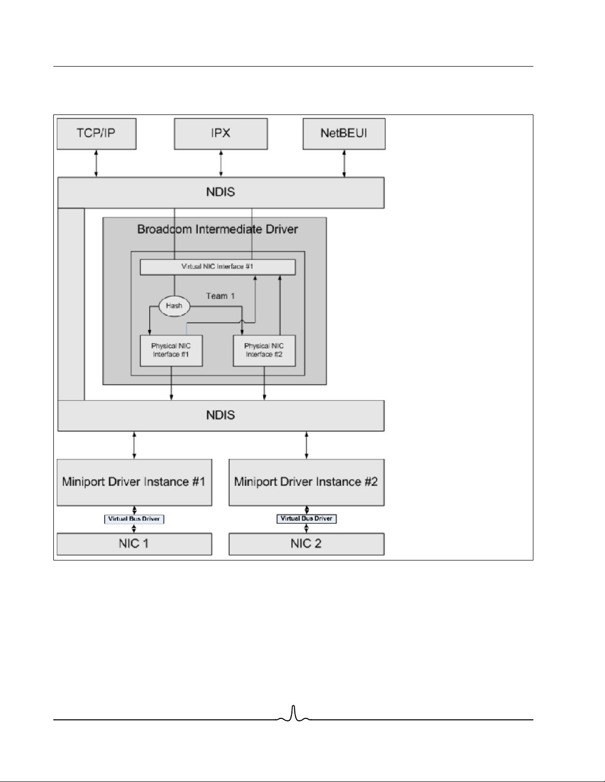
Teaming is implemented via an NDIS intermediate driver in the Windows Operating System environment. This software
component works with the miniport driver, the NDIS layer, and the protocol stack to enable the teaming architecture (see
Figure 2). The miniport driver controls the host LAN controller directly to enable functions such as sends, receives, and
interrupt processing. The intermediate driver fits between the miniport driver and the protocol layer multiplexing several
miniport driver instances, and creating a virtual adapter that looks like a single adapter to the NDIS layer. NDIS provides a
Broadcom Corporation
Document ENGSRVT52-CDUM100-R Executive Summary Page 21
Page 22

NetXtreme II User Guide
January 2010
set of library functions to enable the communications between either miniport drivers or intermediate drivers and the protocol
stack. The protocol stack implements IP, IPX and ARP. A protocol address such as an IP address is assigned to each
miniport device instance, but when an Intermediate driver is installed, the protocol address is assigned to the virtual team
adapter and not to the individual miniport devices that make up the team.
The Broadcom supplied teaming support is provided by three individual software components that work together and are
supported as a package. When one component is upgraded, all the other components must be upgraded to the supported
versions. Table 3 describes the four software components and their associated files for supported operating systems.
Table 3: Broadcom Teaming Software Component
Software
Component
Miniport Driver Broadcom Base Driver Windows 2000 Server (NDIS 5.0) bxnd50x.sys
Intermediate
Driver
Configuration
User Interface
Broadcom Name Network Adapter/Operating System
Virtual Bus Driver
(VBD)
Broadcom Advanced
Server Program
(BASP)
Broadcom Advanced
Control Suite 3
(BACS)
BCM5706, BCM5708, BCM5709 32-bit bxvbdx.sys
BCM5706, BCM5708, BCM5709 64-bit bxvbda.sys
BCM57710, BCM57711 32-bit evbdx.sys
BCM57710, BCM57711 64-bit evbda.sys
Windows Server 2003 (NDIS 5.1) 32-bit bxnd51x.sys
Windows Server 2003 (NDIS 5.1) 64-bit bxnd51a.sys
Windows Server 2003 (NDIS 5.2)
Driver supports Layer 4
Windows Server 2003 (NDIS 5.2)
Driver supports Layer 4
Windows Server 2008 (NDIS 6.0) 32-bit bxnd60x.sys
Windows Server 2008 (NDIS 6.0) 64-bit bxnd60a.sys
Windows Server 2008 R2 (NDIS 6.0) 64-bit bxnd60a.sys
Windows 2000 Server 32-bit baspw2k.sys
Windows Server 2003 32-bit baspxp32.sys
Windows Server 2003 64-bit basamd64.sys
Windows Server 2008 32-bit, 64-bit basp.sys
Windows Server 2008 R2 64-bit basp.sys
––bacs.exe
System
Architecture
32-bit bxnd52x.sys
64-bit bxnd52a.sys
Windows File
Name
Broadcom Corporation
Page 22 Executive Summary Document ENGSRVT52-CDUM100-R
Page 23

User Guide NetXtreme II
January 2010
HARDWARE REQUIREMENTS
• Repeater Hub
• Switching Hub
•Router
The various teaming modes described in this document place certain restrictions on the networking equipment used to
connect clients to teamed systems. Each type of network interconnect technology has an effect on teaming as described in
the following sections.
Repeater Hub
A Repeater Hub allows a network administrator to extend an Ethernet network beyond the limits of an individual segment.
The repeater regenerates the input signal received on one port onto all other connected ports, forming a single collision
domain. This means that when a station attached to a repeater sends an Ethernet frame to another station, every station
within the same collision domain will also receive that message. If two stations begin transmitting at the same time, a collision
occurs, and each transmitting station must retransmit its data after waiting a random amount of time.
The use of a repeater requires that each station participating within the collision domain operate in half-duplex mode.
Although half-duplex mode is supported for Gigabit Ethernet adapters in the IEEE 802.3 specification, half-duplex mode is
not supported by the majority of Gigabit Ethernet adapter manufacturers. Therefore, half-duplex mode is not considered
here.
Teaming across hubs is supported for troubleshooting purposes (such as connecting a network analyzer) for SLB teams
only.
Switching Hub
Unlike a repeater hub, a switching hub (or more simply a switch) allows an Ethernet network to be broken into multiple
collision domains. The switch is responsible for forwarding Ethernet packets between hosts based solely on Ethernet MAC
addresses. A physical network adapter that is attached to a switch may operate in half-duplex or full-duplex mode.
To support Generic Trunking and 802.3ad Link Aggregation, a switch must specifically support such functionality. If the
switch does not support these protocols, it may still be used for Smart Load Balancing.
NOTE: All modes of network teaming are supported across switches when operating as a stackable switch.
Router
A router is designed to route network traffic based on Layer 3 or higher protocols, although it often also works as a Layer 2
device with switching capabilities. The teaming of ports connected directly to a router is not supported.
Broadcom Corporation
Document ENGSRVT52-CDUM100-R Executive Summary Page 23
Page 24

NetXtreme II User Guide
January 2010
TEAMING SUPPORT BY PROCESSOR
All team types are supported by the IA-32, AMD-64, and EM64T processors.
CONFIGURING TEAMING
The Broadcom Advanced Control Suite 3 utility is used to configure teaming in the supported operating system
environments.
The Broadcom Advanced Control Suite 3 (BACS) utility is designed to run on 32-bit and 64-bit Windows family of operating
systems. BACS 3 is used to configure load balancing and fault tolerance teaming, and VLANs. In addition, it displays the
MAC address, driver version, and status information about each network adapter. BACS 3 also includes a number of
diagnostics tools such as hardware diagnostics, cable testing, and a network topology test.
SUPPORTED FEATURES BY TEAM TYPE
Table 4 provides a feature comparison across the team types. Use this table to determine the best type of team for your
application. The teaming software supports up to eight ports in a single team and up to four teams in a single system. The
four teams can be any combination of the supported teaming types, but each team must be on a separate network or subnet.
Table 4: Comparison of Team Types
Type of Team Fault Tolerance Load Balancing
Function
Number of ports per
team (same
broadcast domain)
Number of teams 4 4 4 4
Adapter fault
tolerance
Switch link fault
tolerance (same
broadcast domain)
TX load balancing No Yes Yes Yes
RX load balancing No Yes Yes (performed by the
Requires compatible
switch
Heartbeats to check
connectivity
Mixed media
(adapters with
different media)
SLB with Standby
2–8 2–8 2–8 2–8
Yes Yes Yes Yes
Yes Yes Switch-dependent Switch-dependent
No No Yes Yes
No No No No
Yes Yes Yes (switch-
a
SLB Generic Trunking Link Aggregation
Switch-Dependent
Static Trunking
switch)
dependent)
Switch-Independent
Dynamic Link
Aggregation
(IEEE 802.3ad)
Yes (performed by the
switch)
Yes
Broadcom Corporation
Page 24 Executive Summary Document ENGSRVT52-CDUM100-R
Page 25

User Guide NetXtreme II
January 2010
Table 4: Comparison of Team Types (Cont.)
Switch-Independent
Type of Team Fault Tolerance Load Balancing
Switch-Dependent
Static Trunking
Dynamic Link
Aggregation
(IEEE 802.3ad)
Function
Mixed speeds
SLB with Standby
Yes Yes No No
a
SLB Generic Trunking Link Aggregation
(adapters that do not
support a common
speed(s), but can
operate at different
speeds)
Mixed speeds
(adapters that support
Yes Yes No (must be the same
speed)
Yes
a common speed(s),
but can operate at
different speeds)
Load balances TCP/IPNo Yes Yes Yes
Mixed vendor teaming
Yes
b
Load balances non-IP No Yes (IPX outbound
Yes
b
Yes
b
Yes
Yes Yes
traffic only)
Same MAC address
No No Yes Yes
for all team members
Same IP address for
Yes Yes Yes Yes
all team members
Load balancing by IP
No Yes Yes Yes
address
Load balancing by
MAC address
Allows TOE
No Yes (used for no-IP/
Yes Yes
IPX)
Yes Yes No No
functionality to coexist when all team
members support
c
TOE
b
a
SLB with one primary and one standby member.
b
Requires at least one Broadcom adapter in the team.
c TOE functionality can only be achieved with SLB teams that consist of all Broadcom TOE-enabled adapters.
Broadcom Corporation
Document ENGSRVT52-CDUM100-R Executive Summary Page 25
Page 26
NetXtreme II User Guide
January 2010
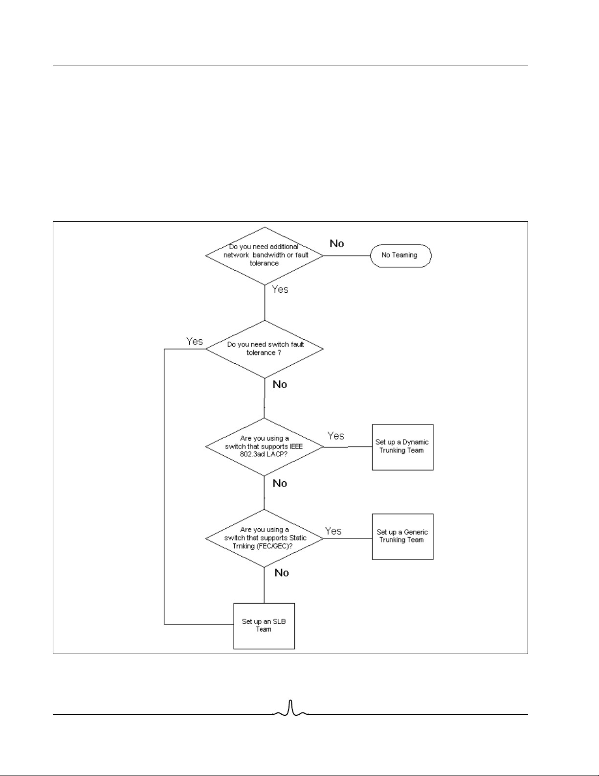
SELECTING A TEAM TYPE
The following flow chart provides the decision flow when planning for Layer 2 teaming. For TOE teaming, only Smart Load
Balancing™ and Failover type team is supported. The primary rationale for teaming is the need for additional network
bandwidth and fault tolerance. Teaming offers link aggregation and fault tolerance to meet both of these requirements.
Preference teaming should be selected in the following order: Link Aggregation as the first choice, Generic Trunking as the
second choice, and SLB teaming as the third choice when using unmanaged switches or switches that do not support the
first two options. if switch fault tolerance is a requirement, then SLB is the only choice (see Figure 1).
Figure 1: Process for Selecting a Team Type
Broadcom Corporation
Page 26 Executive Summary Document ENGSRVT52-CDUM100-R
Page 27

User Guide NetXtreme II
January 2010
TEAMING MECHANISMS
• Architecture
• Types of Teams
• Attributes of the Features Associated with Each Type of Team
• Speeds Supported for Each Type of Team
ARCHITECTURE
The Broadcom Advanced Server Program is implemented as an NDIS intermediate driver (see Figure 2). It operates below
protocol stacks such as TCP/IP and IPX and appears as a virtual adapter. This virtual adapter inherits the MAC Address of
the first port initialized in the team. A Layer 3 address must also be configured for the virtual adapter. The primary function
of BASP is to balance inbound (for SLB) and outbound traffic (for all teaming modes) among the physical adapters installed
on the system selected for teaming. The inbound and outbound algorithms are independent and orthogonal to each other.
The outbound traffic for a particular session can be assigned to a given port while its corresponding inbound traffic can be
assigned to a different port.
Broadcom Corporation
Document ENGSRVT52-CDUM100-R Teaming Mechanisms Page 27
Page 28
NetXtreme II User Guide
January 2010
Figure 2: Intermediate Driver
Outbound Traffic Flow
The Broadcom Intermediate Driver manages the outbound traffic flow for all teaming modes. For outbound traffic, every
packet is first classified into a flow, and then distributed to the selected physical adapter for transmission. The flow
classification involves an efficient hash computation over known protocol fields. The resulting hash value is used to index
into an Outbound Flow Hash Table.The selected Outbound Flow Hash Entry contains the index of the selected physical
adapter responsible for transmitting this flow. The source MAC address of the packets will then be modified to the MAC
address of the selected physical adapter. The modified packet is then passed to the selected physical adapter for
transmission.
Broadcom Corporation
Page 28 Teaming Mechanisms Document ENGSRVT52-CDUM100-R
Page 29

User Guide NetXtreme II
January 2010
The outbound TCP and UDP packets are classified using Layer 3 and Layer 4 header information. This scheme improves
the load distributions for popular Internet protocol services using well-known ports such as HTTP and FTP. Therefore, BASP
performs load balancing on a TCP session basis and not on a packet-by-packet basis.
In the Outbound Flow Hash Entries, statistics counters are also updated after classification. The load-balancing engine uses
these counters to periodically distribute the flows across teamed ports. The outbound code path has been designed to
achieve best possible concurrency where multiple concurrent accesses to the Outbound Flow Hash Table are allowed.
For protocols other than TCP/IP, the first physical adapter will always be selected for outbound packets. The exception is
Address Resolution Protocol (ARP), which is handled differently to achieve inbound load balancing.
Inbound Traffic Flow (SLB Only)
The Broadcom intermediate driver manages the inbound traffic flow for the SLB teaming mode. Unlike outbound load
balancing, inbound load balancing can only be applied to IP addresses that are located in the same subnet as the loadbalancing server. Inbound load balancing exploits a unique characteristic of Address Resolution Protocol (RFC0826), in
which each IP host uses its own ARP cache to encapsulate the IP Datagram into an Ethernet frame. BASP carefully
manipulates the ARP response to direct each IP host to send the inbound IP packet to the desired physical adapter.
Therefore, inbound load balancing is a plan-ahead scheme based on statistical history of the inbound flows. New
connections from a client to the server will always occur over the primary physical adapter (because the ARP Reply
generated by the operating system protocol stack will always associate the logical IP address with the MAC address of the
primary physical adapter).
Like the outbound case, there is an Inbound Flow Head Hash Table. Each entry inside this table has a singly linked list and
each link (Inbound Flow Entries) represents an IP host located in the same subnet.
When an inbound IP Datagram arrives, the appropriate Inbound Flow Head Entry is located by hashing the source IP
address of the IP Datagram. Two statistics counters stored in the selected entry are also updated. These counters are used
in the same fashion as the outbound counters by the load-balancing engine periodically to reassign the flows to the physical
adapter.
On the inbound code path, the Inbound Flow Head Hash Table is also designed to allow concurrent access. The link lists of
Inbound Flow Entries are only referenced in the event of processing ARP packets and the periodic load balancing. There is
no per packet reference to the Inbound Flow Entries. Even though the link lists are not bounded; the overhead in processing
each non-ARP packet is always a constant. The processing of ARP packets, both inbound and outbound, however, depends
on the number of links inside the corresponding link list.
On the inbound processing path, filtering is also employed to prevent broadcast packets from looping back through the
system from other physical adapters.
Protocol Support
ARP and IP/TCP/UDP flows are load balanced. If the packet is an IP protocol only, such as ICMP or IGMP, then all data
flowing to a particular IP address will go out through the same physical adapter. If the packet uses TCP or UDP for the L4
protocol, then the port number is added to the hashing algorithm, so two separate L4 flows can go out through two separate
physical adapters to the same IP address.
For example, assume the client has an IP address of 10.0.0.1. All IGMP and ICMP traffic will go out the same physical
adapter because only the IP address is used for the hash. The flow would look something like this:
IGMP ------> PhysAdapter1 ------> 10.0.0.1
Broadcom Corporation
Document ENGSRVT52-CDUM100-R Teaming Mechanisms Page 29
Page 30

NetXtreme II User Guide
January 2010
ICMP ------> PhysAdapter1 ------> 10.0.0.1
If the server also sends an TCP and UDP flow to the same 10.0.0.1 address, they can be on the same physical adapter as
IGMP and ICMP, or on completely different physical adapters from ICMP and IGMP. The stream may look like this:
IGMP ------> PhysAdapter1 ------> 10.0.0.1
ICMP ------> PhysAdapter1 ------> 10.0.0.1
TCP------> PhysAdapter1 ------> 10.0.0.1
UDP------> PhysAdatper1 ------> 10.0.0.1
Or the streams may look like this:
IGMP ------> PhysAdapter1 ------> 10.0.0.1
ICMP ------> PhysAdapter1 ------> 10.0.0.1
TCP------> PhysAdapter2 ------> 10.0.0.1
UDP------> PhysAdatper3 ------> 10.0.0.1
The actual assignment between adapters may change over time, but any protocol that is not TCP/UDP based goes over the
same physical adapter because only the IP address is used in the hash.
Performance
Modern network interface cards provide many hardware features that reduce CPU utilization by offloading certain CPU
intensive operations (see Teaming and Other Advanced Networking Properties). In contrast, the BASP intermediate driver
is a purely software function that must examine every packet received from the protocol stacks and react to its contents
before sending it out through a particular physical interface. Though the BASP driver can process each outgoing packet in
near constant time, some applications that may already be CPU bound may suffer if operated over a teamed interface. Such
an application may be better suited to take advantage of the failover capabilities of the intermediate driver rather than the
load balancing features, or it may operate more efficiently over a single physical adapter that provides a particular hardware
feature such as Large Send Offload.
TYPES OF TEAMS
Switch-Independent
The Broadcom Smart Load Balancing type of team allows two to eight physical adapters to operate as a single virtual
adapter. The greatest benefit of the SLB type of team is that it operates on any IEEE compliant switch and requires no special
configuration.
Smart Load Balancing and Failover
SLB provides for switch-independent, bidirectional, fault-tolerant teaming and load balancing. Switch independence implies
that there is no specific support for this function required in the switch, allowing SLB to be compatible with all switches. Under
SLB, all adapters in the team have separate MAC addresses. The load-balancing algorithm operates on Layer 3 addresses
of the source and destination nodes, which enables SLB to load balance both incoming and outgoing traffic.
Broadcom Corporation
Page 30 Teaming Mechanisms Document ENGSRVT52-CDUM100-R
Page 31

User Guide NetXtreme II
January 2010
The BASP intermediate driver continually monitors the physical ports in a team for link loss. In the event of link loss on any
port, traffic is automatically diverted to other ports in the team. The SLB teaming mode supports switch fault tolerance by
allowing teaming across different switches- provided the switches are on the same physical network or broadcast domain.
Network Communications
The following are the key attributes of SLB:
• Failover mechanism – Link loss detection.
• Load Balancing Algorithm – Inbound and outbound traffic are balanced through a Broadcom proprietary mechanism
based on L4 flows.
• Outbound Load Balancing using MAC Address - No.
• Outbound Load Balancing using IP Address - Yes
• Multivendor Teaming – Supported (must include at least one Broadcom Ethernet adapter as a team member).
Applications
The SLB algorithm is most appropriate in home and small business environments where cost is a concern or with commodity
switching equipment. SLB teaming works with unmanaged Layer 2 switches and is a cost-effective way of getting
redundancy and link aggregation at the server. Smart Load Balancing also supports teaming physical adapters with differing
link capabilities. In addition, SLB is recommended when switch fault tolerance with teaming is required.
Configuration Recommendations
SLB supports connecting the teamed ports to hubs and switches if they are on the same broadcast domain. It does not
support connecting to a router or Layer 3 switches because the ports must be on the same subnet.
Broadcom Corporation
Document ENGSRVT52-CDUM100-R Teaming Mechanisms Page 31
Page 32

NetXtreme II User Guide
January 2010
Switch-Dependent
Generic Static Trunking
This mode supports a variety of environments where the adapter link partners are statically configured to support a
proprietary trunking mechanism. This mode could be used to support Lucent’s
(FEC), and Cisco’s
needs to assign the ports to the team, and this assignment cannot be altered by the BASP, as there is no exchange of the
Link Aggregation Control Protocol (LACP) frame.
With this mode, all adapters in the team are configured to receive packets for the same MAC address. Trunking operates on
Layer 2 addresses and supports load balancing and failover for both inbound and outbound traffic. The BASP driver
determines the load-balancing scheme for outbound packets, using Layer 4 protocols previously discussed, whereas the
team link partner determines the load-balancing scheme for inbound packets.
The attached switch must support the appropriate trunking scheme for this mode of operation. Both the BASP and the switch
continually monitor their ports for link loss. In the event of link loss on any port, traffic is automatically diverted to other ports
in the team.
Network Communications
Gigabit EtherChannel
(GEC). In the static mode, as in generic link aggregation, the switch administrator
Open Trunk
, Cisco’s
Fast EtherChannel
The following are the key attributes of Generic Static Trunking:
• Failover mechanism – Link loss detection
• Load Balancing Algorithm – Outbound traffic is balanced through Broadcom proprietary mechanism based L4 flows.
Inbound traffic is balanced according to a switch specific mechanism.
• Outbound Load Balancing using MAC Address – No
• Outbound Load Balancing using IP Address - Yes
• Multivendor teaming – Supported (Must include at least one Broadcom Ethernet adapter as a team member)
Applications
Generic trunking works with switches that support Cisco Fast EtherChannel, Cisco Gigabit EtherChannel, Extreme Networks
Load Sharing and Bay Networks or IEEE 802.3ad Link Aggregation static mode. Since load balancing is implemented on
Layer 2 addresses, all higher protocols such as IP, IPX, and NetBEUI are supported. Therefore, this is the recommended
teaming mode when the switch supports generic trunking modes over SLB.
Configuration Recommendations
Static trunking supports connecting the teamed ports to switches if they are on the same broadcast domain and support
generic trunking. It does not support connecting to a router or Layer 3 switches since the ports must be on the same subnet.
Broadcom Corporation
Page 32 Teaming Mechanisms Document ENGSRVT52-CDUM100-R
Page 33

User Guide NetXtreme II
January 2010
Dynamic Trunking (IEEE 802.3ad Link Aggregation)
This mode supports link aggregation through static and dynamic configuration via the Link Aggregation Control Protocol
(LACP). With this mode, all adapters in the team are configured to receive packets for the same MAC address. The MAC
address of the first adapter in the team is used and cannot be substituted for a different MAC address. The BASP driver
determines the load-balancing scheme for outbound packets, using Layer 4 protocols previously discussed, whereas the
team’s link partner determines the load-balancing scheme for inbound packets. Because the load balancing is implemented
on Layer 2, all higher protocols such as IP, IPX, and NetBEUI are supported. The attached switch must support the 802.3ad
Link Aggregation standard for this mode of operation. The switch manages the inbound traffic to the adapter while the BASP
manages the outbound traffic. Both the BASP and the switch continually monitor their ports for link loss. In the event of link
loss on any port, traffic is automatically diverted to other ports in the team.
Network Communications
The following are the key attributes of Dynamic Trunking:
• Failover mechanism – Link loss detection
• Load Balancing Algorithm – Outbound traffic is balanced through a Broadcom proprietary mechanism based on L4
flows. Inbound traffic is balanced according to a switch specific mechanism.
• Outbound Load Balancing using MAC Address - No
• Outbound Load Balancing using IP Address - Yes
• Multivendor teaming – Supported (Must include at least one Broadcom Ethernet adapter as a team member)
Applications
Dynamic trunking works with switches that support IEEE 802.3ad Link Aggregation dynamic mode using LACP. Inbound
load balancing is switch dependent. In general, the switch traffic is load balanced based on L2 addresses. In this case, all
network protocols such as IP, IPX, and NetBEUI are load balanced. Therefore, this is the recommended teaming mode when
the switch supports LACP, except when switch fault tolerance is required. SLB is the only teaming mode that supports switch
fault tolerance.
Configuration Recommendations
Dynamic trunking supports connecting the teamed ports to switches as long as they are on the same broadcast domain and
supports IEEE 802.3ad LACP trunking. It does not support connecting to a router or Layer 3 switches since the ports must
be on the same subnet.
LiveLink™
LiveLink™ is a feature of BASP that is available for the Smart Load Balancing (SLB) and SLB (Auto-Fallback Disable) type
of teaming. The purpose of LiveLink is to detect link loss beyond the switch and to route traffic only through team members
that have a live link. This function is accomplished though the teaming software. The teaming software periodically probes
(issues a link packet from each team member) one or more specified target network device(s). The probe target(s) responds
when it receives the link packet. If a team member does not detect the response within a specified amount of time, this
indicates that the link has been lost, and the teaming software discontinues passing traffic through that team member. Later,
if that team member begins to detect a response from a probe target, this indicates that the link has been restored, and the
teaming software automatically resumes passing traffic through that team member. LiveLink works only with TCP/IP.
LiveLink™ functionality is supported in both 32-bit and 64-bit Windows operating systems. For similar functionality in Linux
operating systems, see the Channel Bonding information in your Red Hat documentation.
Broadcom Corporation
Document ENGSRVT52-CDUM100-R Teaming Mechanisms Page 33
Page 34

NetXtreme II User Guide
January 2010
ATTRIBUTES OF THE FEATURES ASSOCIATED WITH EACH TYPE OF TEAM
The attributes of the features associated with each type of team are summarized in Table 5.
Table 5: Attributes
Feature Attribute
Smart Load Balancing™
User interface Broadcom Advanced Control Suite 3 (BACS)
Number of teams Maximum 8
Number of adapters per team Maximum 8
Hot replace Yes
Hot add Yes
Hot remove Yes
Link speed support Different speeds
Frame protocol IP
Incoming packet management BASP
Outgoing packet management BASP
LiveLink support Yes
Failover event Loss of link
Failover time <500 ms
Fallback time
MAC address Different
Multivendor teaming Yes
Generic Trunking
User interface Broadcom Advanced Control Suite 3 (BACS)
Number of teams Maximum 8
Number of adapters per team Maximum 8
Hot replace Yes
Hot add Yes
Hot remove Yes
Link speed support
Frame protocol All
Incoming packet management Switch
Outgoing packet management BASP
Failover event Loss of link only
Failover time <500 ms
Fallback time
MAC address Same for all adapters
Multivendor teaming Yes
Dynamic Trunking
User interface Broadcom Advanced Control Suite 3 (BACS)
Number of teams Maximum 8
Number of adapters per team Maximum 8
b
(approximate)
1.5 s
Different speeds
b
(approximate)
1.5 s
a
Broadcom Corporation
Page 34 Teaming Mechanisms Document ENGSRVT52-CDUM100-R
Page 35

User Guide NetXtreme II
January 2010
Table 5: Attributes (Cont.)
Feature Attribute
Hot replace Yes
Hot add Yes
Hot remove Yes
Link speed support Different speeds
Frame protocol All
Incoming packet management Switch
Outgoing packet management BASP
Failover event Loss of link only
Failover time <500 ms
Fallback time
MAC address Same for all adapters
Multivendor teaming Yes
a
Some switches require matching link speeds to correctly negotiate between trunk connections.
b
Make sure that Port Fast or Edge Port is enabled.
b
(approximate)
1.5 s
SPEEDS SUPPORTED FOR EACH TYPE OF TEAM
The various link speeds that are supported for each type of team are listed in Table 6. Mixed speed refers to the capability
of teaming adapters that are running at different link speeds.
Table 6: Link Speeds in Teaming
Type of Team Link Speed Traffic Direction Speed Support
SLB 10/100/1000/10000 Incoming/outgoing Mixed speed
FEC 100 Incoming/outgoing Same speed
GEC 1000 Incoming/outgoing Same speed
IEEE 802.3ad 10/100/1000/10000 Incoming/outgoing Mixed speed
Broadcom Corporation
Document ENGSRVT52-CDUM100-R Teaming Mechanisms Page 35
Page 36

NetXtreme II User Guide
January 2010
TEAMING AND OTHER ADVANCED NETWORKING PROPERTIES
• Checksum Offload
• IEEE 802.1p QoS Tagging
• Large Send Offload
• TCP Offload Engine (TOE)
• Jumbo Frames
• IEEE 802.1Q VLANs
• Wake On LAN
• Preboot Execution Environment
Before creating a team, adding or removing team members, or changing advanced settings of a team member, make sure
each team member has been configured similarly. Settings to check include VLANs and QoS Packet Tagging, Jumbo
Frames, and the various offloads. Advanced adapter properties and teaming support are listed in Table 7.
Table 7: Advanced Adapter Properties and Teaming Support
Adapter Properties Supported by Teaming Virtual Adapter
Checksum Offload Yes
IEEE 802.1p QoS Tagging No
Large Send Offload
TCP Offload Engine (TOE)
Jumbo Frames
IEEE 802.1Q VLANs
Yes
Yes
Yes
Yes
a
b, c
b
c
Wake on LAN No
Preboot Execution environment (PXE)
a
All adapters on the team must support this feature. Some adapters may not support this feature if ASF/IPMI is also enabled.
b
Must be supported by all adapters in the team.
c
Only for Broadcom adapters.
d
As a PXE sever only, not as a client.
Yes
d
A team does not necessarily inherit adapter properties; rather various properties depend on the specific capability. For
instance, an example would be flow control, which is a physical adapter property and has nothing to do with BASP, and will
be enabled on a particular adapter if the miniport driver for that adapter has flow control enabled.
NOTE: All adapters on the team must support the property listed in Table 7 in order for the team to support the
property.
Broadcom Corporation
Page 36 Teaming and Other Advanced Networking Properties Document ENGSRVT52-CDUM100-R
Page 37

User Guide NetXtreme II
January 2010
CHECKSUM OFFLOAD
Checksum Offload is a property of the Broadcom network adapters that allows the TCP/IP/UDP checksums for send and
receive traffic to be calculated by the adapter hardware rather than by the host CPU. In high-traffic situations, this can allow
a system to handle more connections more efficiently than if the host CPU were forced to calculate the checksums. This
property is inherently a hardware property and would not benefit from a software-only implementation. An adapter that
supports Checksum Offload advertises this capability to the operating system so that the checksum does not need to be
calculated in the protocol stack. Checksum Offload is only supported for IPv4 at this time.
IEEE 802.1P QOS TAGGING
The IEEE 802.1p standard includes a 3-bit field (supporting a maximum of 8 priority levels), which allows for traffic
prioritization. The BASP intermediate driver does not support IEEE 802.1p QoS tagging.
LARGE SEND OFFLOAD
Large Send Offload (LSO) is a feature provided by Broadcom network adapters that prevents an upper level protocol such
as TCP from breaking a large data packet into a series of smaller packets with headers appended to them. The protocol
stack need only generate a single header for a data packet as large as 64 KB, and the adapter hardware breaks the data
buffer into appropriately-sized Ethernet frames with the correctly sequenced header (based on the single header originally
provided).
TCP OFFLOAD ENGINE (TOE)
The TCP/IP protocol suite is used to provide transport services for a wide range of applications for the Internet, LAN, and
for file transfer. Without the TCP Offload Engine, the TCP/IP protocol suite runs on the host CPU, consuming a very high
percentage of its resources and leaving little resources for the applications. With the use of the Broadcom NetXtreme II
adapter, the TCP/IP processing can be moved to hardware, freeing the CPU for more important tasks such as application
processing.
The Broadcom NetXtreme II adapter's TOE functionality allows simultaneous operation of up to 1024 fully offloaded TCP
connections for 1-Gbps network adapters and 1880 fully offloaded TCP connections for 10-Gbps network adapters. The
TOE support on the adapter significantly reduces the host CPU utilization while preserving the implementation of the
operating system stack.
JUMBO FRAMES
The use of jumbo frames was originally proposed by Alteon Networks, Inc. in 1998 and increased the maximum size of an
Ethernet frame to a maximum size of 9000 bytes. Though never formally adopted by the IEEE 802.3 Working Group, support
for jumbo frames has been implemented in Broadcom NetXtreme II adapters. The BASP intermediate driver supports jumbo
frames, provided that all of the physical adapters in the team also support jumbo frames and the same size is set on all
adapters in the team.
IEEE 802.1Q VLANS
In 1998, the IEEE approved the 802.3ac standard, which defines frame format extensions to support Virtual Bridged Local
Area Network tagging on Ethernet networks as specified in the IEEE 802.1Q specification. The VLAN protocol permits
Broadcom Corporation
Document ENGSRVT52-CDUM100-R Teaming and Other Advanced Networking Properties Page 37
Page 38

NetXtreme II User Guide
January 2010
insertion of a tag into an Ethernet frame to identify the VLAN to which a frame belongs. If present, the 4-byte VLAN tag is
inserted into the Ethernet frame between the source MAC address and the length/type field. The first 2-bytes of the VLAN
tag consist of the IEEE 802.1Q tag type, whereas the second 2 bytes include a user priority field and the VLAN identifier
(VID). Virtual LANs (VLANs) allow the user to split the physical LAN into logical subparts. Each defined VLAN behaves as
its own separate network, with its traffic and broadcasts isolated from the others, thus increasing bandwidth efficiency within
each logical group. VLANs also enable the administrator to enforce appropriate security and quality of service (QoS) policies.
The BASP supports the creation of 64 VLANs per team or adapter: 63 tagged and 1 untagged. The operating system and
system resources, however, limit the actual number of VLANs. VLAN support is provided according to IEEE 802.1Q and is
supported in a teaming environment as well as on a single adapter. Note that VLANs are supported only with homogeneous
teaming and not in a multivendor teaming environment. The BASP intermediate driver supports VLAN tagging. One or more
VLANs may be bound to a single instance of the intermediate driver.
WAKE ON LAN
Wake on LAN (WOL) is a feature that allows a system to be awakened from a sleep state by the arrival of a specific packet
over the Ethernet interface. Because a Virtual Adapter is implemented as a software only device, it lacks the hardware
features to implement Wake on LAN and cannot be enabled to wake the system from a sleeping state via the Virtual Adapter.
The physical adapters, however, support this property, even when the adapter is part of a team.
PREBOOT EXECUTION ENVIRONMENT
The Preboot Execution Environment (PXE) allows a system to boot from an operating system image over the network. By
definition, PXE is invoked before an operating system is loaded, so there is no opportunity for the BASP intermediate driver
to load and enable a team. As a result, teaming is not supported as a PXE client, though a physical adapter that participates
in a team when the operating system is loaded may be used as a PXE client. Whereas a teamed adapter cannot be used
as a PXE client, it can be used for a PXE server, which provides operating system images to PXE clients using a combination
of Dynamic Host Control Protocol (DHCP) and the Trivial File Transfer Protocol (TFTP). Both of these protocols operate over
IP and are supported by all teaming modes.
Broadcom Corporation
Page 38 Teaming and Other Advanced Networking Properties Document ENGSRVT52-CDUM100-R
Page 39

User Guide NetXtreme II
January 2010
GENERAL NETWORK CONSIDERATIONS
• Teaming with Microsoft Virtual Server 2005
• Teaming Across Switches
• Spanning Tree Algorithm
• Layer 3 Routing/Switching
• Teaming with Hubs (for troubleshooting purposes only)
• Teaming with Microsoft NLB
TEAMING WITH MICROSOFT VIRTUAL SERVER 2005
The only supported BASP team configuration when using Microsoft Virtual Server 2005 is with a Smart Load Balancing (TM)
team-type consisting of a single primary Broadcom adapter and a standby Broadcom adapter. Make sure to unbind or
deselect “Virtual Machine Network Services” from each team member prior to creating a team and prior to creating Virtual
networks with Microsoft Virtual Server. Additionally, a virtual network should be created in this software and subsequently
bound to the virtual adapter created by a team. Directly binding a Guest operating system to a team virtual adapter may not
render the desired results.
NOTE: As of this writing, Windows Server 2008 is not a supported operating system for Microsoft Virtual Server
2005; thus, teaming may not function as expected with this combination.
TEAMING ACROSS SWITCHES
SLB teaming can be configured across switches. The switches, however, must be connected together. Generic Trunking
and Link Aggregation do not work across switches because each of these implementations requires that all physical
adapters in a team share the same Ethernet MAC address. It is important to note that SLB can only detect the loss of link
between the ports in the team and their immediate link partner. SLB has no way of reacting to other hardware failures in the
switches and cannot detect loss of link on other ports.
Switch-Link Fault Tolerance
The diagrams below describe the operation of an SLB team in a switch fault tolerant configuration. We show the mapping
of the ping request and ping replies in an SLB team with two active members. All servers (Blue, Gray and Red) have a
continuous ping to each other. Figure 3 is a setup without the interconnect cable in place between the two switches. Figure 4
has the interconnect cable in place, and Figure 5 is an example of a failover event with the Interconnect cable in place. These
scenarios describe the behavior of teaming across the two switches and the importance of the interconnect link.
The diagrams show the secondary team member sending the ICMP echo requests (yellow arrows) while the primary team
member receives the respective ICMP echo replies (blue arrows). This illustrates a key characteristic of the teaming
software. The load balancing algorithms do not synchronize how frames are load balanced when sent or received. In other
words, frames for a given conversation can go out and be received on different interfaces in the team. This is true for all
Broadcom Corporation
Document ENGSRVT52-CDUM100-R General Network Considerations Page 39
Page 40

NetXtreme II User Guide
January 2010
types of teaming supported by Broadcom. Therefore, an interconnect link must be provided between the switches that
connect to ports in the same team.
In the configuration without the interconnect, an ICMP Request from Blue to Gray goes out port 82:83 destined for Gray port
5E:CA, but the Top Switch has no way to send it there because it cannot go along the 5E:C9 port on Gray. A similar scenario
occurs when Gray attempts to ping Blue. An ICMP Request goes out on 5E:C9 destined for Blue 82:82, but cannot get there.
Top Switch does not have an entry for 82:82 in its CAM table because there is no interconnect between the two switches.
Pings, however, flow between Red and Blue and between Red and Gray.
Furthermore, a failover event would cause additional loss of connectivity. Consider a cable disconnect on the Top Switch
port 4. In this case, Gray would send the ICMP Request to Red 49:C9, but because the Bottom switch has no entry for 49:C9
in its CAM Table, the frame is flooded to all its ports but cannot find a way to get to 49:C9.
Figure 3: Teaming Across Switches Without an Interswitch Link
Broadcom Corporation
Page 40 General Network Considerations Document ENGSRVT52-CDUM100-R
Page 41
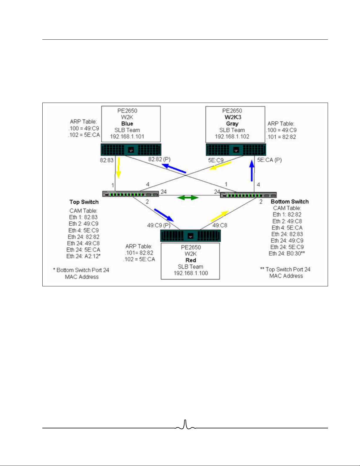
User Guide NetXtreme II
January 2010
The addition of a link between the switches allows traffic from/to Blue and Gray to reach each other without any problems.
Note the additional entries in the CAM table for both switches. The link interconnect is critical for the proper operation of the
team. As a result, it is highly advisable to have a link aggregation trunk to interconnect the two switches to ensure high
availability for the connection.
Figure 4: Teaming Across Switches With Interconnect
Broadcom Corporation
Document ENGSRVT52-CDUM100-R General Network Considerations Page 41
Page 42
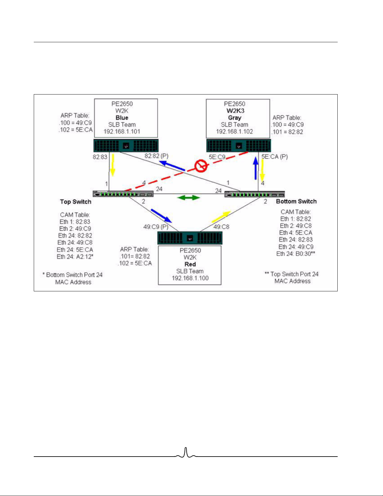
NetXtreme II User Guide
January 2010
Figure 5 represents a failover event in which the cable is unplugged on the Top Switch port 4. This is a successful failover
with all stations pinging each other without loss of connectivity.
Figure 5: Failover Event
Broadcom Corporation
Page 42 General Network Considerations Document ENGSRVT52-CDUM100-R
Page 43

User Guide NetXtreme II
January 2010
SPANNING TREE ALGORITHM
• Topology Change Notice (TCN)
• Port Fast/Edge Port
In Ethernet networks, only one active path may exist between any two bridges or switches. Multiple active paths between
switches can cause loops in the network. When loops occur, some switches recognize stations on both sides of the switch.
This situation causes the forwarding algorithm to malfunction allowing duplicate frames to be forwarded. Spanning tree
algorithms provide path redundancy by defining a tree that spans all of the switches in an extended network and then forces
certain redundant data paths into a standby (blocked) state. At regular intervals, the switches in the network send and
receive spanning tree packets that they use to identify the path. If one network segment becomes unreachable, or if spanning
tree costs change, the spanning tree algorithm reconfigures the spanning tree topology and re-establishes the link by
activating the standby path. Spanning tree operation is transparent to end stations, which do not detect whether they are
connected to a single LAN segment or a switched LAN of multiple segments.
Spanning Tree Protocol (STP) is a Layer 2 protocol designed to run on bridges and switches. The specification for STP is
defined in IEEE 802.1d. The main purpose of STP is to ensure that you do not run into a loop situation when you have
redundant paths in your network. STP detects/disables network loops and provides backup links between switches or
bridges. It allows the device to interact with other STP compliant devices in your network to ensure that only one path exists
between any two stations on the network.
After a stable network topology has been established, all bridges listen for hello BPDUs (Bridge Protocol Data Units)
transmitted from the root bridge. If a bridge does not get a hello BPDU after a predefined interval (Max Age), the bridge
assumes that the link to the root bridge is down. This bridge then initiates negotiations with other bridges to reconfigure the
network to re-establish a valid network topology. The process to create a new topology can take up to 50 seconds. During
this time, end-to-end communications are interrupted.
The use of Spanning Tree is not recommended for ports that are connected to end stations, because by definition, an end
station does not create a loop within an Ethernet segment. Additionally, when a teamed adapter is connected to a port with
Spanning Tree enabled, users may experience unexpected connectivity problems. For example, consider a teamed adapter
that has a lost link on one of its physical adapters. If the physical adapter were to be reconnected (also known as fallback),
the intermediate driver would detect that the link has been reestablished and would begin to pass traffic through the port.
Traffic would be lost if the port was temporarily blocked by the Spanning Tree Protocol.
Topology Change Notice (TCN)
A bridge/switch creates a forwarding table of MAC addresses and port numbers by learning the source MAC address that
received on a particular port. The table is used to forward frames to a specific port rather than flooding the frame to all ports.
The typical maximum aging time of entries in the table is 5 minutes. Only when a host has been silent for 5 minutes would
its entry be removed from the table. It is sometimes beneficial to reduce the aging time. One example is when a forwarding
link goes to blocking and a different link goes from blocking to forwarding. This change could take up to 50 seconds. At the
end of the STP re-calculation a new path would be available for communications between end stations. However, because
the forwarding table would still have entries based on the old topology, communications may not be reestablished until after
5 minutes when the affected ports entries are removed from the table. Traffic would then be flooded to all ports and relearned. In this case it is beneficial to reduce the aging time. This is the purpose of a topology change notice (TCN) BPDU.
The TCN is sent from the affected bridge/switch to the root bridge/switch. As soon as a bridge/switch detects a topology
change (a link going down or a port going to forwarding) it sends a TCN to the root bridge via its root port. The root bridge
then advertises a BPDU with a Topology Change to the entire network.This causes every bridge to reduce the MAC table
aging time to 15 seconds for a specified amount of time. This allows the switch to re-learn the MAC addresses as soon as
STP re-converges.
Broadcom Corporation
Document ENGSRVT52-CDUM100-R General Network Considerations Page 43
Page 44

NetXtreme II User Guide
January 2010
Topology Change Notice BPDUs are sent when a port that was forwarding changes to blocking or transitions to forwarding.
A TCN BPDU does not initiate an STP recalculation. It only affects the aging time of the forwarding table entries in the
switch.It will not change the topology of the network or create loops. End nodes such as servers or clients trigger a topology
change when they power off and then power back on.
Port Fast/Edge Port
To reduce the effect of TCNs on the network (for example, increasing flooding on switch ports), end nodes that are powered
on/off often should use the Port Fast or Edge Port setting on the switch port they are attached to. Port Fast or Edge Port is
a command that is applied to specific ports and has the following effects:
• Ports coming from link down to link up will be put in the forwarding STP mode instead of going from listening to learning
and then to forwarding. STP is still running on these ports.
• The switch does not generate a Topology Change Notice when the port is going up or down.
LAYER 3 ROUTING/SWITCHING
The switch that the teamed ports are connected to must not be a Layer 3 switch or router. The ports in the team must be in
the same network.
TEAMING WITH HUBS (FOR TROUBLESHOOTING PURPOSES ONLY)
• Hub Usage in Teaming Network Configurations
• SLB Teams
• SLB Team Connected to a Single Hub
• Generic and Dynamic Trunking (FEC/GEC/IEEE 802.3ad)
SLB teaming can be used with 10/100 hubs, but it is only recommended for troubleshooting purposes, such as connecting
a network analyzer in the event that switch port mirroring is not an option.
Hub Usage in Teaming Network Configurations
Although the use of hubs in network topologies is functional in some situations, it is important to consider the throughput
ramifications when doing so. Network hubs have a maximum of 100 Mbps half-duplex link speed, which severely degrades
performance in either a Gigabit or 100 Mbps switched-network configuration. Hub bandwidth is shared among all connected
devices; as a result, when more devices are connected to the hub, the bandwidth available to any single device connected
to the hub is reduced in direct proportion to the number of devices connected to the hub.
It is not recommended to connect team members to hubs; only switches should be used to connect to teamed ports. An SLB
team, however, can be connected directly to a hub for troubleshooting purposes. Other team types can result in a loss of
connectivity if specific failures occur and should not be used with hubs.
SLB Teams
SLB teams are the only teaming type not dependant on switch configuration. The server intermediate driver handles the load
balancing and fault tolerance mechanisms with no assistance from the switch. These elements of SLB make it the only team
type that maintains failover and fallback characteristics when team ports are connected directly to a hub.
Broadcom Corporation
Page 44 General Network Considerations Document ENGSRVT52-CDUM100-R
Page 45

User Guide NetXtreme II
January 2010
SLB Team Connected to a Single Hub
SLB teams configured as shown in Figure 6 maintain their fault tolerance properties. Either server connection could
potentially fail, and network functionality is maintained. Clients could be connected directly to the hub, and fault tolerance
would still be maintained; server performance, however, would be degraded.
Figure 6: Team Connected to a Single Hub
Generic and Dynamic Trunking (FEC/GEC/IEEE 802.3ad)
FEC/GEC and IEEE 802.3ad teams cannot be connected to any hub configuration. These team types must be connected
to a switch that has also been configured for this team type.
TEAMING WITH MICROSOFT NLB
Teaming
mechanism used by the NLB service, the recommended teaming configuration in this environment is Failover (SLB with a
standby NIC) as load balancing is managed by NLB. The TOE functionality in teaming will not operate in NLB.
Document ENGSRVT52-CDUM100-R General Network Considerations Page 45
does not
work in Microsoft’s Network Load Balancing (NLB) unicast mode, only in multicast mode. Due to the
Broadcom Corporation
Page 46

NetXtreme II User Guide
January 2010
APPLICATION CONSIDERATIONS
• Teaming and Clustering
• Teaming and Network Backup
TEAMING AND CLUSTERING
• Microsoft Cluster Software
• High-Performance Computing Cluster
•Oracle
Microsoft Cluster Software
MSCS clusters support up to two nodes if you are using Windows 2000 Server. If you are using Windows Server 2003,
MSCS clusters support up to eight nodes. In each cluster node, it is strongly recommended that customers install at least
two network adapters (on-board adapters are acceptable). These interfaces serve two purposes. One adapter is used
exclusively for intra-cluster
separate private subnetwork. The other adapter is used for client communications and is referred to as the
heartbeat
communications. This is referred to as the
private adapter
and usually resides on a
public adapter
.
Multiple adapters may be used for each of these purposes: private, intracluster communications and public, external client
communications. All Broadcom teaming modes are supported with Microsoft Cluster Software for the public adapter only.
Private network adapter teaming is not supported. Microsoft indicates that the use of teaming on the private interconnect of
a server cluster is not supported because of delays that could possibly occur in the transmission and receipt of heartbeat
packets between the nodes. For best results, when you want redundancy for the private interconnect, disable teaming and
use the available ports to form a second private interconnect. This achieves the same end result and provides dual, robust
communication paths for the nodes to communicate over.
For teaming in a clustered environment, customers are recommended to use the same brand of adapters.
Broadcom Corporation
Page 46 Application Considerations Document ENGSRVT52-CDUM100-R
Page 47

User Guide NetXtreme II
January 2010
Figure 7 shows a 2-node Fibre-Channel cluster with three network interfaces per cluster node: one private and two public.
On each node, the two public adapters are teamed, and the private adapter is not. Teaming is supported across the same
switch or across two switches. Figure 8 shows the same 2-node Fibre-Channel cluster in this configuration.
Figure 7: Clustering With Teaming Across One Switch
NOTE: Microsoft Network Load Balancing is not supported with Microsoft Cluster Software.
Broadcom Corporation
Document ENGSRVT52-CDUM100-R Application Considerations Page 47
Page 48

NetXtreme II User Guide
January 2010
High-Performance Computing Cluster
Gigabit Ethernet is typically used for the following three purposes in high-performance computing cluster (HPCC)
applications:
• Inter-Process Communications (IPC): For applications that do not require low-latency, high-bandwidth interconnects
(such as Myrinet, InfiniBand), Gigabit Ethernet can be used for communication between the compute nodes.
• I/O: Ethernet can be used for file sharing and serving the data to the compute nodes. This can be done simply using an
NFS server or using parallel file systems such as PVFS.
• Management & Administration: Ethernet is used for out-of-band (ERA) and in-band (OMSA) management of the nodes
in the cluster. It can also be used for job scheduling and monitoring.
In our current HPCC offerings, only one of the on-board adapters is used. If Myrinet or IB is present, this adapter serves I/
O and administration purposes; otherwise, it is also responsible for IPC. In case of an adapter failure, the administrator can
use the Felix package to easily configure adapter 2. Adapter teaming on the host side is neither tested nor supported in
HPCC.
Advanced Features
PXE is used extensively for the deployment of the cluster (installation and recovery of compute nodes). Teaming is typically
not used on the host side and it is not a part of our standard offering. Link aggregation is commonly used between switches,
especially for large configurations. Jumbo frames, although not a part of our standard offering, may provide performance
improvement for some applications due to reduced CPU overhead.
Broadcom Corporation
Page 48 Application Considerations Document ENGSRVT52-CDUM100-R
Page 49

User Guide NetXtreme II
January 2010
Oracle
In our Oracle Solution Stacks, we support adapter teaming in both the private network (interconnect between RAC nodes)
and public network with clients or the application layer above the database layer.
Figure 8: Clustering With Teaming Across Two Switches
Broadcom Corporation
Document ENGSRVT52-CDUM100-R Application Considerations Page 49
Page 50

NetXtreme II User Guide
January 2010
TEAMING AND NETWORK BACKUP
• Load Balancing and Failover
• Fault Tolerance
When you perform network backups in a nonteamed environment, overall throughput on a backup server adapter can be
easily impacted due to excessive traffic and adapter overloading. Depending on the number of backup servers, data
streams, and tape drive speed, backup traffic can easily consume a high percentage of the network link bandwidth, thus
impacting production data and tape backup performance. Network backups usually consist of a dedicated backup server
running with tape backup software such as NetBackup, Galaxy or Backup Exec. Attached to the backup server is either a
direct SCSI tape backup unit or a tape library connected through a fiber channel storage area network (SAN). Systems that
are backed up over the network are typically called clients or remote servers and usually have a tape backup software agent
installed. Figure 9 shows a typical 1 Gbps nonteamed network environment with tape backup implementation.
Figure 9: Network Backup without Teaming
Broadcom Corporation
Page 50 Application Considerations Document ENGSRVT52-CDUM100-R
Page 51

User Guide NetXtreme II
January 2010
Because there are four client servers, the backup server can simultaneously stream four backup jobs (one per client) to a
multidrive autoloader. Because of the single link between the switch and the backup server; however, a 4-stream backup
can easily saturate the adapter and link. If the adapter on the backup server operates at 1 Gbps (125 MB/s), and each client
is able to stream data at 20 MB/s during tape backup, the throughput between the backup server and switch will be at 80
MB/s (20 MB/s x 4), which is equivalent to 64% of the network bandwidth. Although this is well within the network bandwidth
range, the 64% constitutes a high percentage, especially if other applications share the same link.
Load Balancing and Failover
As the number of backup streams increases, the overall throughput increases. Each data stream, however, may not be able
to maintain the same performance as a single backup stream of 25 MB/s. In other words, even though a backup server can
stream data from a single client at 25 MB/s, it is not expected that four simultaneously-running backup jobs will stream at
100 MB/s (25 MB/s x 4 streams). Although overall throughput increases as the number of backup streams increases, each
backup stream can be impacted by tape software or network stack limitations.
For a tape backup server to reliably use adapter performance and network bandwidth when backing up clients, a network
infrastructure must implement teaming such as load balancing and fault tolerance. Data centers will incorporate redundant
switches, link aggregation, and trunking as part of their fault tolerant solution. Although teaming device drivers will
manipulate the way data flows through teamed interfaces and failover paths, this is transparent to tape backup applications
and does not interrupt any tape backup process when backing up remote systems over the network. Figure 10 shows a
network topology that demonstrates tape backup in a Broadcom teamed environment and how smart load balancing can
load balance
tape backup data across teamed adapters.
There are four paths that the client-server can use to send data to the backup server, but only one of these paths will be
designated during data transfer. One possible path that Client-Server Red can use to send data to the backup server is:
Example Path: Client-Server Red sends data through Adapter A, Switch 1, Backup Server Adapter A.
The designated path is determined by two factors:
• Client-Server ARP cache; which points to the backup server MAC address. This is determined by the Broadcom
intermediate driver inbound load balancing algorithm.
• The physical adapter interface on Client-Server Red will be used to transmit the data. The Broadcom intermediate
driver outbound load balancing algorithm determines this (see Outbound Traffic Flow and Inbound Traffic Flow (SLB
Only).
The teamed interface on the backup server transmits a gratuitous address resolution protocol (G-ARP) to Client-Server Red,
which in turn, causes the client server ARP cache to get updated with the Backup Server MAC address. The load balancing
mechanism within the teamed interface determines the MAC address embedded in the G-ARP. The selected MAC address
is essentially the destination for data transfer from the client server.On Client-Server Red, the SLB teaming algorithm will
determine which of the two adapter interfaces will be used to transmit data. In this example, data from Client Server Red is
received on the backup server Adapter A interface. To demonstrate the SLB mechanisms when additional load is placed on
the teamed interface, consider the scenario when the backup server initiates a second backup operation: one to ClientServer Red, and one to Client-Server Blue. The route that Client-Server Blue uses to send data to the backup server is
dependant on its ARP cache, which points to the backup server MAC address. Because Adapter A of the backup server is
already under load from its backup operation with Client-Sever Red, the Backup Server invokes its SLB algorithm to
Client-Server Blue (through an G-ARP) to update its ARP cache to reflect the backup server Adapter B MAC address. When
Client-Server Blue needs to transmit data, it uses either one of its adapter interfaces, which is determined by its own SLB
algorithm. What is important is that data from Client-Server Blue is received by the Backup Server Adapter B interface, and
not by its Adapter A interface. This is important because with both backup streams running simultaneously, the backup
server must
the backup server is processing an equal load, thus load-balancing data across both adapter interfaces.
load balance
data streams from different clients. With both backup streams running, each adapter interface on
inform
Broadcom Corporation
Document ENGSRVT52-CDUM100-R Application Considerations Page 51
Page 52

NetXtreme II User Guide
January 2010
The same algorithm applies if a third and fourth backup operation is initiated from the backup server. The teamed interface
on the backup server transmits a unicast G-ARP to backup clients to inform them to update their ARP cache. Each client
then transmits backup data along a route to the target MAC address on the backup server.
Fault Tolerance
If a network link fails during tape backup operations, all traffic between the backup server and client stops and backup jobs
fail. If, however, the network topology was configured for both Broadcom SLB and switch fault tolerance, then this would
allow tape backup operations to continue without interruption during the link failure. All failover processes within the network
are transparent to tape backup software applications. To understand how backup data streams are directed during network
failover process, consider the topology in Figure 10. Client-Server Red is transmitting data to the backup server through Path
1, but a link failure occurs between the backup server and the switch. Because the data can no longer be sent from Switch
#1 to the Adapter A interface on the backup server, the data is redirected from Switch #1 through Switch #2, to the Adapter
B interface on the backup server. This occurs without the knowledge of the backup application because all fault tolerant
operations are handled by the adapter team interface and trunk settings on the switches. From the client server perspective,
it still operates as if it is transmitting data through the original path.
Figure 10: Network Backup With SLB Teaming Across Two Switches
Broadcom Corporation
Page 52 Application Considerations Document ENGSRVT52-CDUM100-R
Page 53

User Guide NetXtreme II
January 2010
Broadcom Corporation
Document ENGSRVT52-CDUM100-R Application Considerations Page 53
Page 54

NetXtreme II User Guide
January 2010
TROUBLESHOOTING TEAMING PROBLEMS
• Teaming Configuration Tips
• Troubleshooting Guidelines
When running a protocol analyzer over a virtual adapter teamed interface, the MAC address shown in the transmitted frames
may not be correct. The analyzer does not show the frames as constructed by BASP and shows the MAC address of the
team and not the MAC address of the interface transmitting the frame. It is suggested to use the following process to monitor
a team:
• Mirror all uplink ports from the team at the switch.
• If the team spans two switches, mirror the interlink trunk as well.
• Sample all mirror ports independently.
• On the analyzer, use an adapter and driver that does not filter QoS and VLAN information.
TEAMING CONFIGURATION TIPS
When troubleshooting network connectivity or teaming functionality issues, ensure that the following information is true for
your configuration.
1. Although mixed-speed SLB teaming is supported, it is recommended that all adapters in a team be the same speed
(either all Gigabit Ethernet or all Fast Ethernet). For speeds of 10 Gbps, it is highly recommended that all adapters in a
team be the same speed.
2. If LiveLink is not enabled, disable Spanning Tree Protocol or enable an STP mode that bypasses the initial phases (for
example, Port Fast, Edge Port) for the switch ports connected to a team.
3. All switches that the team is directly connected to must have the same hardware revision, firmware revision, and software
revision to be supported.
4. To be teamed, adapters should be members of the same VLAN. In the event that multiple teams are configured, each
team should be on a separate network.
5. Do not assign a Locally Administered Address on any physical adapter that is a member of a team.
6. Verify that power management is disabled on all physical members of any team.
7. Remove any static IP address from the individual physical team members before the team is built.
8. A team that requires maximum throughput should use LACP or GEC\FEC. In these cases, the intermediate driver is only
responsible for the outbound load balancing while the switch performs the inbound load balancing.
9. Aggregated teams (802.3ad \ LACP and GEC\FEC) must be connected to only a single switch that supports IEEE
802.3a, LACP or GEC/FEC.
10. It is not recommended to connect any team to a hub, as a hub only support half duplex. Hubs should be connected to a
team for troubleshooting purposes only. Disabling the device driver of a network adapter participating in an LACP or
GEC/FEC team may have adverse affects with network connectivity. Broadcom recommends that the adapter first be
physically disconnected from the switch before disabling the device driver in order to avoid a network connection loss.
11. Verify the base (Miniport) and team (intermediate) drivers are from the same release package. The mixing of base and
teaming drivers from different releases is not supported.
12. Test the connectivity to each physical adapter prior to teaming.
13. Test the failover and fallback behavior of the team before placing into a production environment.
14. When moving from a nonproduction network to a production network, it is strongly recommended to test again for failover
Broadcom Corporation
Page 54 Troubleshooting Teaming Problems Document ENGSRVT52-CDUM100-R
Page 55

User Guide NetXtreme II
January 2010
and fallback.
15. Test the performance behavior of the team before placing into a production environment.
16. Network teaming is not supported when running iSCSI traffic via Microsoft iSCSI initiator or iSCSI offload. MPIO should
be used instead of Broadcom network teaming for these ports.
17. For information on iSCSI boot and iSCSI offload restrictions, see iSCSI Protocol.
TROUBLESHOOTING GUIDELINES
Before you call for support, make sure you have completed the following steps for troubleshooting network connectivity
problems when the server is using adapter teaming.
1. Make sure the link light is ON for every adapter and all the cables are attached.
2. Check that the matching base and intermediate drivers belong to the same release and are loaded correctly.
3. Check for a valid IP Address using the Windows ipconfig command.
4. Check that STP is disabled or Edge Port/Port Fast is enabled on the switch ports connected to the team or that LiveLink
is being used.
5. Check that the adapters and the switch are configured identically for link speed and duplex.
6. If possible, break the team and check for connectivity to each adapter independently to confirm that the problem is
directly associated with teaming.
7. Check that all switch ports connected to the team are on the same VLAN.
8. Check that the switch ports are configured properly for Generic Trunking (FEC/GEC)/802.3ad-Draft Static type of
teaming and that it matches the adapter teaming type. If the system is configured for an SLB type of team, make sure
the corresponding switch ports
are not
configured for Generic Trunking (FEC/GEC)/802.3ad-Draft Static types of teams.
FREQUENTLY ASKED QUESTIONS
Question: Under what circumstances is traffic not load balanced? Why is all traffic not load balanced evenly across the team
members?
Answer: The bulk of traffic does not use IP/TCP/UDP or the bulk of the clients are in a different network. The receive load
balancing is not a function of traffic load, but a function of the number of clients that are connected to the server.
Question: What network protocols are load balanced when in a team?
Answer: Broadcom’s teaming software only supports IP/TCP/UDP traffic. All other traffic is forwarded to the primary adapter.
Question: Which protocols are load balanced with SLB and which ones are not?
Answer: Only IP/TCP/UDP protocols are load balanced in both directions: send and receive. IPX is load balanced on the
transmit traffic only.
Question: Can I team a port running at 100 Mbps with a port running at 1000 Mbps?
Answer: Mixing link speeds within a team is only supported for Smart Load Balancing™ teams and 802.3ad teams.
Question: Can I team a fiber adapter with a copper Gigabit Ethernet adapter?
Answer: Yes with SLB, and yes if the switch allows for it in FEC/GEC and 802.3ad.
Question: What is the difference between adapter load balancing and Microsoft’s Network Load Balancing (NLB)?
Answer: Adapter load balancing is done at a network session level, whereas NLB is done at the server application level.
Broadcom Corporation
Document ENGSRVT52-CDUM100-R Frequently Asked Questions Page 55
Page 56

NetXtreme II User Guide
January 2010
Question: Can I connect the teamed adapters to a hub?
Answer: Teamed ports can be connected to a hub for troubleshooting purposes only. However, this practice is not
recommended for normal operation because the performance would be degraded due to hub limitations. Connect the
teamed ports to a switch instead.
Question: Can I connect the teamed adapters to ports in a router?
Answer: No. All ports in a team must be on the same network; in a router, however, each port is a separate network by
definition. All teaming modes require that the link partner be a Layer 2 switch.
Question: Can I use teaming with Microsoft Cluster Services?
Answer: Yes. Teaming is supported on the public network only, not on the private network used for the heartbeat link.
Question: Can PXE work over a virtual adapter (team)?
Answer: A PXE client operates in an environment before the operating system is loaded; as a result, virtual adapters have
not been enabled yet. If the physical adapter supports PXE, then it can be used as a PXE client, whether or not it is part of
a virtual adapter when the operating system loads. PXE servers may operate over a virtual adapter.
Question: Can WOL work over a virtual adapter (team)?
Answer: Wake-on-LAN functionality operates in an environment before the operating system is loaded. WOL occurs when
the system is off or in standby, so no team is configured.
Question: What is the maximum number of ports that can be teamed together?
Answer: Up to eight ports can be assigned to a team.
Question: What is the maximum number of teams that can be configured on the same server?
Answer: Up to eight teams can be configured on the same server.
Question: Why does my team loose connectivity for the first 30 to 50 seconds after the Primary adapter is restored
(fallback)?
Answer: Because Spanning Tree Protocol is bringing the port from blocking to forwarding. You must enable Port Fast or
Edge Port on the switch ports connected to the team or use LiveLink to account for the STP delay.
Question: Can I connect a team across multiple switches?
Answer: Smart Load Balancing can be used with multiple switches because each physical adapter in the system uses a
unique Ethernet MAC address. Link Aggregation and Generic Trunking cannot operate across switches because they
require all physical adapters to share the same Ethernet MAC address.
Question: How do I upgrade the intermediate driver (BASP)?
Answer: The intermediate driver cannot be upgraded through the Local Area Connection Properties. It must be upgraded
using the Setup installer.
Question: How can I determine the performance statistics on a virtual adapter (team)?
Answer: In Broadcom Advanced Control Suite 3, click the Statistics tab for the virtual adapter.
Question: Can I configure NLB and teaming concurrently?
Answer: Yes, but only when running NLB in a multicast mode (NLB is not supported with MS Cluster Services).
Question: Should both the backup server and client servers that are backed up be teamed?
Answer: Because the backup server is under the most data load, it should always be teamed for link aggregation and
failover. A fully redundant network, however, requires that both the switches and the backup clients be teamed for fault
tolerance and link aggregation.
Broadcom Corporation
Page 56 Frequently Asked Questions Document ENGSRVT52-CDUM100-R
Page 57

User Guide NetXtreme II
January 2010
Question: During backup operations, does the adapter teaming algorithm load balance data at a byte-level or a sessionlevel?
Answer: When using adapter teaming, data is only load balanced at a session level and not a byte level to prevent out-oforder frames. Adapter teaming load balancing does not work the same way as other storage load balancing mechanisms
such as EMC PowerPath.
Question: Is there any special configuration required in the tape backup software or hardware to work with adapter teaming?
Answer: No special configuration is required in the tape software to work with teaming. Teaming is transparent to tape
backup applications.
Question: How do I know what driver I am currently using?
Answer: In all operating systems, the most accurate method for checking the driver revision is to physically locate the driver
file and check the properties.
Question: Can SLB detect a switch failure in a Switch Fault Tolerance configuration?
Answer: No. SLB can only detect the loss of link between the teamed port and its immediate link partner. SLB cannot detect
link failures on other ports.
Question: Why does my team lose connectivity for the first 30 to 50 seconds after the primary adapter is restored (fall-back
after a failover)?
Answer: During a fall-back event, link is restored causing Spanning Tree Protocol to configure the port for blocking until it
determines that it can move to the forwarding state. You must enable Port Fast or Edge Port on the switch ports connected
to the team to prevent the loss of communications caused by STP.
Question: Where do I monitor real time statistics for an adapter team in a Windows server?
Answer: Use the Broadcom Advanced Control Suite 3 (BACS) to monitor general, IEEE 802.3 and custom counters.
Question: What features are not supported on a multivendor team?
Answer: TOE, VLAN tagging, and RSS are not supported on a multivendor team.
Broadcom Corporation
Document ENGSRVT52-CDUM100-R Frequently Asked Questions Page 57
Page 58

NetXtreme II User Guide
January 2010
APPENDIX A: EVENT LOG MESSAGES
• Windows System Event Log messages
• Base Driver (Physical Adapter/Miniport)
• Intermediate Driver (Virtual Adapter/Team)
WINDOWS SYSTEM EVENT LOG MESSAGES
The known base and intermediate Windows System Event Log status messages for the Broadcom NetXtreme II adapters
are listed in Table 8 and Table 9. As a Broadcom adapter driver loads, Windows places a status code in the system event
viewer. There may be up to two classes of entries for these event codes depending on whether both drivers are loaded (one
set for the base or miniport driver and one set for the intermediate or teaming driver).
BASE DRIVER (PHYSICAL ADAPTER/MINIPORT)
The base driver is identified by source L2ND. Table 8 lists the event log messages supported by the base driver, explains
the cause for the message, and provides the recommended action.
Note: In Table 8, message numbers 1 through 17 apply to both NDIS 5.x and NDIS 6.x drivers, message numbers
18 through 23 apply only to the NDIS 6.x driver.
Table 8: Base Driver Event Log Messages
Message
Number
1 Error Failed to allocate memory
2 Error Failed to allocate map
3 Error Failed to access
4 Warning The network link is down.
5 Informational The network link is up. The adapter has established a
6 Informational Network controller
Severity Message Cause Corrective Action
The driver cannot allocate
for the device block. Check
system memory resource
usage.
registers.
configuration information.
Reinstall the network
driver.
Check to make sure the
network cable is properly
connected.
configured for 10Mb halfduplex link.
memory from the operating
system.
The driver cannot allocate
map registers from the
operating system.
The driver cannot access PCI
configuration space registers
on the adapter.
The adapter has lost its
connection with its link partner.
link.
The adapter has been
manually configured for the
selected line speed and
duplex settings.
Close running applications to
free memory.
Unload other drivers that may
allocate map registers.
For add-in adapters: reseat the
adapter in the slot, move the
adapter to another PCI slot, or
replace the adapter.
Check that the network cable is
connected, verify that the
network cable is the right type,
and verify that the link partner
(for example, switch or hub) is
working correctly.
No action is required.
No action is required.
Broadcom Corporation
Page 58 Appendix A: Event Log Messages Document ENGSRVT52-CDUM100-R
Page 59

User Guide NetXtreme II
January 2010
Table 8: Base Driver Event Log Messages (Cont.)
Message
Number
7 Informational Network controller
8 Informational Network controller
9 Informational Network controller
10 Informational Network controller
11 Informational Network controller
12 Informational Network controller
13 Error Medium not supported. The operating system does
14 Error Unable to register the
15 Error Unable to map IO space. The device driver cannot
16 Informational Driver initialized
17 Informational NDIS is resetting the
18 Error Unknown PHY detected.
19 Error This driver does not
Severity Message Cause Corrective Action
configured for 10Mb fullduplex link.
configured for 100Mb halfduplex link.
configured for 100Mb fullduplex link.
configured for 1Gb halfduplex link.
configured for 1Gb fullduplex link.
configured for 2.5Gb fullduplex link.
interrupt service routine.
successfully.
miniport driver.
Using a default PHY
initialization routine.
support this device.
Upgrade to the latest
driver.
The adapter has been
manually configured for the
selected line speed and
duplex settings.
The adapter has been
manually configured for the
selected line speed and
duplex settings.
The adapter has been
manually configured for the
selected line speed and
duplex settings.
The adapter has been
manually configured for the
selected line speed and
duplex settings.
The adapter has been
manually configured for the
selected line speed and
duplex settings.
The adapter has been
manually configured for the
selected line speed and
duplex settings.
not support the IEEE 802.3
medium.
The device driver cannot
install the interrupt handler.
allocate memory-mapped I/O
to access driver registers.
The driver has successfully
loaded.
The NDIS layer has detected a
problem sending/receiving
packets and is resetting the
driver to resolve the problem.
The driver could not read the
PHY ID.
The driver does not recognize
the installed adapter.
No action is required.
No action is required.
No action is required.
No action is required.
No action is required.
No action is required.
Reboot the operating system,
run a virus check, run a disk
check (chkdsk), and reinstall
the operating system.
Reboot the operating system;
remove other device drivers
that may be sharing the same
IRQ.
Remove other adapters from
the system, reduce the amount
of physical memory installed,
and replace the adapter.
No action is required.
Run Broadcom Advanced
Control Suite 3 diagnostics;
check that the network cable is
good.
Replace the adapter.
Upgrade to a driver version
that supports this adapter.
Broadcom Corporation
Document ENGSRVT52-CDUM100-R Appendix A: Event Log Messages Page 59
Page 60

NetXtreme II User Guide
January 2010
Table 8: Base Driver Event Log Messages (Cont.)
Message
Number
20 Error Driver initialization failed. Unspecified failure during
21 Informational Network controller
22 Error Network controller failed
23 Error Network controller failed to
Severity Message Cause Corrective Action
driver initialization.
configured for 10Gb fullduplex link.
initialization because it
cannot allocate system
memory.
exchange the interface with
the bus driver.
The adapter has been
manually configured for the
selected line speed and
duplex settings.
Insufficient system memory
prevented the initialization of
the driver.
The driver and the bus driver
are not compatible.
Reinstall the driver, update to a
newer driver, run Broadcom
Advanced Control Suite 3
diagnostics, or replace the
adapter.
No action is required.
Increase system memory.
Update to the latest driver set,
ensuring the major and minor
versions for both NDIS and the
bus driver are the same.
Broadcom Corporation
Page 60 Appendix A: Event Log Messages Document ENGSRVT52-CDUM100-R
Page 61

User Guide NetXtreme II
January 2010
INTERMEDIATE DRIVER (VIRTUAL ADAPTER/TEAM)
The intermediate driver is identified by source BLFM, regardless of the base driver revision. Table 9 lists the event log
messages supported by the intermediate driver, explains the cause for the message, and provides the recommended action.
Table 9: Intermediate Driver Event Log Messages
System
Event
Message
Number
1 Informational Event logging enabled for
2 Error Unable to register with
3 Error Unable to instantiate the
4 Error Unable to create symbolic
5 Informational Broadcom Advanced Server
6 Informational Broadcom Advanced Server
7 Error Could not allocate memory
8 Warning Could not bind to adapter. The driver could not open
9 Informational Successfully bind to
10 Warning Network adapter is
11 Informational Network adapter is
12 Error Broadcom Advanced
13 Informational Hot-standby adapter is
Severity Message Cause Corrective Action
Broadcom Advanced Server
Program driver.
NDIS.
management interface.
link for the management
interface.
Program Driver has started.
Program Driver has
stopped.
for internal data structures.
adapter.
disconnected.
connected.
Program Features Driver is
not designed to run on this
version of Operating
System.
selected as the primary
adapter for a team without a
load balancing adapter.
– No action is required.
The driver cannot register
with the NDIS interface.
The driver cannot create a
device instance.
Another driver has created a
conflicting device name.
The driver has started. No action is required.
The driver has stopped. No action is required.
The driver cannot allocate
memory from the operating
system.
one of the team physical
adapters.
The driver successfully
opened the physical
adapter.
The physical adapter is not
connected to the network (it
has not established link).
The physical adapter is
connected to the network (it
has established link).
The driver does not support
the operating system on
which it is installed.
A standby adapter has been
activated.
Unload other NDIS drivers.
Reboot the operating
system.
Unload the conflicting device
driver that uses the name
Blf
.
Close running applications
to free memory.
Unload and reload the
physical adapter driver,
install an updated physical
adapter driver, or replace
the physical adapter.
No action is required.
Check that the network
cable is connected, verify
that the network cable is the
right type, and verify that the
link partner (switch or hub) is
working correctly.
No action is required.
Consult the driver release
notes and install the driver
on a supported operating
system or update the driver.
Replace the failed physical
adapter.
Broadcom Corporation
Document ENGSRVT52-CDUM100-R Appendix A: Event Log Messages Page 61
Page 62

NetXtreme II User Guide
January 2010
Table 9: Intermediate Driver Event Log Messages (Cont.)
System
Event
Message
Number
14 Informational Network adapter does not
15 Informational Network adapter is enabled
16 Warning Network adapter is disabled
17 Informational Network adapter is activated
18 Informational Network adapter is de-
19 Informational The LiveLink feature in
20 Informational The LiveLink feature in
Severity Message Cause Corrective Action
support Advanced Failover.
via management interface.
via management interface.
and is participating in
network traffic.
activated and is no longer
participating in network
traffic.
BASP connected the link for
the network adapter.
BASP disconnected the link
for the network adapter.
The physical adapter does
not support the Broadcom
NIC Extension (NICE).
The driver has successfully
enabled a physical adapter
through the management
interface.
The driver has successfully
disabled a physical adapter
through the management
interface.
A physical adapter has been
added to or activated in a
team.
The driver does not
recognize the installed
adapter.
The connection with the
remote target(s) for the
LiveLink-enabled team
member has been
established or restored
The LiveLink-enabled team
member is unable to
connect with the remote
target(s).
Replace the adapter with
one that does support NICE.
No action is required.
No action is required.
No action is required.
No action is required.
No action is required.
No action is required.
Broadcom Corporation
Page 62 Appendix A: Event Log Messages Document ENGSRVT52-CDUM100-R
Page 63

User Guide NetXtreme II
January 2010
Virtual LANs: Broadcom NetXtreme II™ Network
Adapter User Guide
• VLAN Overview
• Adding VLANs to Teams
VLAN OVERVIEW
Virtual LANs (VLANs) allow you to split your physical LAN into logical parts, to create logical segmentation of workgroups,
and to enforce security policies for each logical segment. Each defined VLAN behaves as its own separate network with its
traffic and broadcasts isolated from the others, increasing bandwidth efficiency within each logical group. Up to 64 VLANs
(63 tagged and 1 untagged) can be defined for each Broadcom adapter on your server, depending on the amount of memory
available in your system.
VLANs can be added to a team to allow multiple VLANs with different VLAN IDs. A virtual adapter is created for each VLAN
added.
Although VLANs are commonly used to create individual broadcast domains and/or separate IP subnets, it is sometimes
useful for a server to have a presence on more than one VLAN simultaneously. Broadcom adapters support multiple VLANs
on a per-port or per-team basis, allowing very flexible network configurations.
Figure 1: Example of Servers Supporting Multiple VLANs with Tagging
Broadcom Corporation
Document ENGSRVT52-CDUM100-R Virtual LANs: Broadcom NetXtreme II™ Network Adapter User Guide Page 63
Page 64

NetXtreme II User Guide
January 2010
Figure 1 shows an example network that uses VLANs. In this example network, the physical LAN consists of a switch, two
servers, and five clients. The LAN is logically organized into three different VLANs, each representing a different IP subnet.
The features of this network are described in Table 1.
Table 1: Example VLAN Network Topology
Component Description
VLAN #1 An IP subnet consisting of the Main Server, PC #3, and PC #5. This subnet
VLAN #2 Includes the Main Server, PCs #1 and #2 via shared media segment, and PC #5.
VLAN #3 Includes the Main Server, the Accounting Server and PC #4. This VLAN is an
Main Server A high-use server that needs to be accessed from all VLANs and IP subnets. The
Accounting Server Available to VLAN #3 only. The Accounting Server is isolated from all traffic on
PCs #1 and #2 Attached to a shared media hub that is then connected to the switch. PCs #1 and
PC #3 A member of VLAN #1, PC #3 can communicate only with the Main Server and
PC #4 A member of VLAN #3, PC #4 can only communicate with the servers. Tagging
PC #5 A member of both VLANs #1 and #2, PC #5 has an Broadcom adapter installed.
represents an engineering group.
This VLAN is a software development group.
accounting group.
Main Server has a Broadcom adapter installed. All three IP subnets are
accessed via the single physical adapter interface. The server is attached to one
of the switch ports, which is configured for VLANs #1, #2, and #3. Both the
adapter and the connected switch port have tagging turned on. Because of the
tagging VLAN capabilities of both devices, the server is able to communicate on
all three IP subnets in this network, but continues to maintain broadcast
separation between all of them.
VLANs #1 and #2. The switch port connected to the server has tagging turned
off.
#2 belong to VLAN #2 only, and are logically in the same IP subnet as the Main
Server and PC #5. The switch port connected to this segment has tagging turned
off.
PC #5. Tagging is not enabled on PC #3 switch port.
is not enabled on PC #4 switch port.
It is connected to switch port #10. Both the adapter and the switch port are
configured for VLANs #1 and #2 and have tagging enabled.
NOTE: VLAN tagging is only required to be enabled on switch ports that create trunk links to other switches, or on
ports connected to tag-capable end-stations, such as servers or workstations with Broadcom adapters.
Broadcom Corporation
Page 64 VLAN Overview Document ENGSRVT52-CDUM100-R
Page 65

User Guide NetXtreme II
January 2010
ADDING VLANS TO TEAMS
Each team supports up to 64 VLANs (63 tagged and 1 untagged). Note that only Broadcom adapters and Alteon® AceNIC
adapters can be part of a team with VLANs. With multiple VLANs on an adapter, a server with a single adapter can have a
logical presence on multiple IP subnets. With multiple VLANs in a team, a server can have a logical presence on multiple IP
subnets and benefit from load balancing and failover. For instructions on adding a VLAN to a team, see Adding a VLAN for
Windows operating systems.
NOTE: Adapters that are members of a failover team can also be configured to support VLANs. Because VLANs
are not supported for an Intel LOM, if an Intel LOM is a member of a failover team, VLANs cannot be configured
for that team.
Broadcom Corporation
Document ENGSRVT52-CDUM100-R Adding VLANs to Teams Page 65
Page 66

NetXtreme II User Guide
January 2010
Manageability: Broadcom NetXtreme II™
Network Adapter User Guide
•CIM
•SNMP
CIM
The Common Information Model (CIM) is an industry standard defined by the Distributed Management Task Force (DMTF).
Microsoft implements CIM on Windows server platforms. Broadcom will support CIM on Windows server platforms.
Broadcom's implementation of CIM will provide various classes to provide information to users through CIM client
applications. Note that Broadcom CIM data provider will provide data only, and users can choose their preferred CIM client
software to browse the information exposed by Broadcom CIM provider.
Broadcom CIM provider provides information through BRCM_NetworkAdapter and BRCM_ExtraCapacityGroup classes.
BRCM_NetworkAdapter class provides network adapter information pertaining to a group of adapters including Broadcom
and other vendors' controllers. BRCM_ExtraCapacityGroup class provides team configuration for the Broadcom Advanced
Server Program. Current implementation will provide team information and information of physical network adapters in the
team.
Broadcom Advanced Server Program provides events through event logs. Users can use the "Event Viewer" provided by
Windows server platforms, or use CIM to inspect or monitor these events. Broadcom CIM provider will also provide event
information through the CIM generic event model. These events are __InstanceCreationEvent, __InstanceDeletionEvent
and __InstanceModificationEvent, and are defined by CIM. CIM requires the client application to register the events from the
client application, using queries as examples shown below in order to receive events properly.
SELECT * FROM __InstanceModificationEvent
where TargetInstance ISA "BRCM_NetworkAdapter"
SELECT * FROM __InstanceModificationEvent
where TargetInstance ISA "BRCM_ExtraCapacityGroup"
SELECT * FROM __InstanceCreationEvent
where TargetInstance ISA "BRCM_NetworkAdapter"
SELECT * FROM __InstanceDeletionEvent
where TargetInstance ISA "BRCM_NetworkAdapter"
SELECT * FROM __InstanceCreationEvent
where TargetInstance ISA "BRCM_ActsAsSpare"
SELECT * FROM __InstanceDeletionEvent
where TargetInstance ISA "BRCM_ActsAsSpare"
For detailed information about these events, see the CIM documentation at http://www.dmtf.org/standards/
published_documents/DSP0004V2.3_final.pdf.
Broadcom Corporation
Page 66 Manageability: Broadcom NetXtreme II™ Network Adapter User Guide Document ENGSRVT52-CDUM100-R
Page 67

User Guide NetXtreme II
January 2010
SNMP
BASP SUBAGENT
The BASP subagent, baspmgnt.dll, is designed for the Windows 2000 Server and Windows Server 2003 SNMP service. It
is required to install the SNMP service before installing the BASP subagent.
The BASP subagent allows an SNMP manager software to actively monitor the configurations and performance of the
Broadcom Advanced Server features. The subagent also provides an alarm trap to an SNMP manager to inform the
manager of any changes to the conditions of the BASP component.
The BASP subagent allows monitoring of the configurations and statistics for the BASP teams, the physical NIC adapters
participating in a team, and the virtual NIC adapters created as the result of teaming. Non-teamed NIC adapters are not
monitored at this time. The BASP configuration data includes information such as team IDs, physical/virtual/VLAN/team
adapter IDs, physical/virtual/VLAN/team/ adapter descriptions, and MAC addresses of the adapters.
The statistics include detailed information such as data packets transmitted and received for the physical/virtual/VLAN/team
adapters.
The alarm trap forwards information about the changes in configuration of the physical adapters participating in a team, such
as physical adapter link up/down, and adapter installed/removed events.
To monitor this information, an SNMP manager must load the Broadcom BASP MIB database files to allow monitoring of the
information described above. These files, which are shown below, are included with the driver source media.
•baspcfg.mib
• baspstat.mib
•basptrap.mib
Broadcom Corporation
Document ENGSRVT52-CDUM100-R SNMP Page 67
Page 68

NetXtreme II User Guide
January 2010
BASP EXTENSIBLE-AGENT
The Broadcom NetXtreme II Gigabit Ethernet Controller Extended Information SNMP extensible-agent (bcmif.dll) is
designed for Windows 2000 Server, Windows Server 2003, and Windows Server 2008 SNMP service. It is required that
Windows 2000 Server SNMP service is installed before installing the extensible-agent.
The extensible-agent allows the SNMP manager software to actively monitor the configurations of the Broadcom NetXtreme
II adapter. It is intended to supplement the information already provided by the standard SNMP Management Network
Interface information.
The extensible-agent provides in-depth information about a Broadcom NetXtreme II adapter such as:
• MAC address
• Bound IP address
• IP subnet mask
• Physical link status
• Adapter state
• Line speed
• Duplex mode
• Memory range
• Interrupt setting
• Bus number
• Device number
• Function number
To monitor this information, a SNMP manager needs to load the Broadcom Extended information MIB file to allow monitoring
of the information described above. This file, bcmif.mib, is included on the installation CD.
The monitored workstation requires the installation of the Broadcom Extended Information SNMP extensible-agent,
bcmif.dll, and requires the Microsoft Windows 2000 Server, Windows Server 2003, and Windows Server 2008 SNMP service
to be installed and loaded.
Broadcom Corporation
Page 68 SNMP Document ENGSRVT52-CDUM100-R
Page 69

User Guide NetXtreme II
January 2010
Installing the Hardware: Broadcom NetXtreme
II™ Network Adapter User Guide
•Overview
• System Requirements
• Safety Precautions
• Preinstallation Checklist
• Installation of the Add-In NIC
OVERVIEW
This section applies to Broadcom NetXtreme II add-in network interface cards.
SYSTEM REQUIREMENTS
Before you install a Broadcom NetXtreme II adapter, verify that your system meets the following hardware and operating
system requirements:
HARDWARE REQUIREMENTS
• IA32- or EMT64-based computer that meets operating system requirements
• One open slot: PCI Express 1.0a x4 or PCI Express Gen2 x8
• 128-MB RAM (minimum)
OPERATING SYSTEM REQUIREMENTS
General
• PCI Express v1.0a, x4 (or greater) Host Interface
Microsoft Windows
One of the following versions of Microsoft Windows:
• Windows 2000 Server family
• Windows Server 2003 family
• Windows Server 2008 family
• Windows Server 2008 R2 family
Broadcom Corporation
Document ENGSRVT52-CDUM100-R Installing the Hardware: Broadcom NetXtreme II™ Network Adapter User Guide Page 69
Page 70

NetXtreme II User Guide
January 2010
Novell NetWare
Novell NetWare 6.5 with the latest support pack.
Linux
Although the adapter driver should work with many Linux kernel versions and distributions, it has only been tested on 2.4x
kernels (starting from 2.4.24) and 2.6.x kernels. The driver may not compile on kernels older than 2.4.24. Testing is
concentrated on i386 and x86_64 architectures. Only limited testing has been done on other architectures. Minor changes
to some source files and Makefile may be needed on some kernels.
NOTE: Support for the 2.4.21 kernels is provided in Red Hat Enterprise Linux 3.
VMware ESX
VMware ESX 3.5
SAFETY PRECAUTIONS
CAUTION! The adapter is being installed in a system that operates with voltages that can be lethal. Before you open
the case of your system, observe the following precautions to protect yourself and to prevent damage to the system
components.
• Remove any metallic objects or jewelry from your hands and wrists.
• Make sure to use only insulated or nonconducting tools.
• Verify that the system is powered OFF and is unplugged before you touch internal components.
• Install or remove adapters in a static-free environment. The use of a properly grounded wrist strap or other
personal antistatic devices and an antistatic mat is strongly recommended.
PREINSTALLATION CHECKLIST
1. Verify that your system meets the hardware and software requirements listed under System Requirements.
2. Verify that your system is using the latest BIOS.
NOTE: If you acquired the adapter software on a disk, verify the path to the adapter driver files.
1. If your system is active, shut it down.
2. When system shutdown is complete, turn off the power and unplug the power cord.
3. Remove the adapter from its shipping package and place it on an antistatic surface.
4. Check the adapter for visible signs of damage, particularly on the edge connector. Never attempt to install a damaged
adapter.
Broadcom Corporation
Page 70 Safety Precautions Document ENGSRVT52-CDUM100-R
Page 71

User Guide NetXtreme II
January 2010
INSTALLATION OF THE ADD-IN NIC
The following instructions apply to installing the Broadcom NetXtreme II adapter (add-in NIC) in most systems. Refer to the
manuals that were supplied with your system for details about performing these tasks on your particular system.
INSTALLING THE ADD-IN NIC
1. Review Safety Precautions and Preinstallation Checklist. Before you install the adapter, ensure that the system power
is OFF, the power cord is unplugged from the power outlet, and that you are following proper electrical grounding
procedures.
2. Open the system case and select the slot based on the adapter: PCI Express 1.0a x4, PCI Express Gen2 x8, or other
appropriate slot. A lesser width adapter can be seated into a greater width slot (x1 in a x4), but a greater width adapter
cannot be seated into a lesser width slot (x4 in a x1). If you do not know how to identify a PCI Express slot, refer to your
system documentation.
3. Remove the blank cover-plate from the slot that you selected.
4. Align the adapter connector edge with the PCI Express connector slot in the system.
5. Applying even pressure at both corners of the card, push the adapter card into the slot until it is firmly seated. When the
adapter is properly seated, the adapter port connectors are aligned with the slot opening, and the adapter faceplate is
flush against the system chassis.
CAUTION! Do not use excessive force when seating the card, as this may damage the system or the adapter. If you
have difficulty seating the adapter, remove it, realign it, and try again.
6. Secure the adapter with the adapter clip or screw.
7. Close the system case and disconnect any personal antistatic devices.
CONNECTING THE NETWORK CABLES
The Broadcom NetXtreme II adapter has either an RJ-45 connector used for attaching the system to an Ethernet copperwire segment or a fiber optic connector for attaching the system to an Ethernet fiber optic segment.
NOTE: This section does not apply to blade servers.
Copper Wire
NOTE: The Broadcom NetXtreme II adapter supports Automatic MDI Crossover (MDIX), which eliminates the need
for crossover cables when connecting machines back-to-back. A straight-through Category 5 cable allows the
machines to communicate when connected directly together.
1. Select an appropriate cable. Table 1 lists the copper cable requirements for connecting to 10/100/1000BASE-T and
10GBASE-T ports:
Broadcom Corporation
Document ENGSRVT52-CDUM100-R Installation of the Add-In NIC Page 71
Page 72

NetXtreme II User Guide
January 2010
Table 1: 10/100/1000BASE-T and 10GBASE-T Cable Specifications
Port Type Connector Media Maximum Distance
10BASE-T RJ-45 Category 3, 4, or 5 unshielded
twisted pairs (UTP)
100/1000BASE-T
1
10GBASE-T RJ-45
RJ-45
Category 5
Category 6
Category 6A
1
1000BASE-T signaling requires four twisted pairs of Category 5 balanced cabling, as specified in ISO/IEC 11801:2002
2
UTP
3
UTP
3
UTP
and ANSI/EIA/TIA-568-B.
2
Category 5 is the minimum requirement. Category 5e and Category 6 are fully supported.
3
10GBASE-T signaling requires four twisted pairs of Category 6 or Category 6A (augmented Category 6) balanced
cabling, as specified in ISO/IEC 11801:2002 and ANSI/TIA/EIA-568-B.
2. Connect one end of the cable to the RJ-45 connector on the adapter.
3. Connect the other end of the cable to an RJ-45 Ethernet network port.
Fiber Optic
100m (328 ft)
100m (328 ft)
50m (164 ft)
100m (328 ft)
1. Select an appropriate cable. Table 2 lists the fiber optic cable requirements for connecting to 1000/2500BASE-X ports:
Table 2: 1000/2500BASE-X Fiber Optic Specifications
Port Type Connector Media Maximum Distance
1000BASE-X Small form factor (SFF)
transceiver with LC™
connection system
Multimode fiber (MMF)
System optimized for 62.5/
50 µm graded index fiber
550m (1804 ft)
(Infineon p/n V23818-K305L57)
2500BASE-X
1
Small form factor (SFF)
transceiver with LC™
connection system
Multimode fiber (MMF)
System optimized for 62.5/
50 µm graded index fiber
550m (1804 ft)
(Finisar p/n
FTLF8542E2KNV)
1
Electricals leveraged from IEEE 802.3ae-2002 (XAUI). 2500BASE-X is term used by Broadcom to describe 2.5 Gbit/s
(3.125GBd) operation. LC is a trademark of Lucent Technologies.
2. Connect one end of the cable to the fiber optic connector on the adapter.
3. Connect the other end of the cable to an fiber optic Ethernet network port.
Broadcom Corporation
Page 72 Installation of the Add-In NIC Document ENGSRVT52-CDUM100-R
Page 73

User Guide NetXtreme II
January 2010
Broadcom Boot Agent Driver Software:
Broadcom NetXtreme II™ Network Adapter User
Guide
•Overview
• Setting Up MBA in a Client Environment
• Setting Up MBA in a Server Environment
OVERVIEW
Broadcom NetXtreme II adapters support Preboot Execution Environment (PXE), Remote Program Load (RPL), iSCSI, and
Bootstrap Protocol (BootP). Multi-Boot Agent (MBA) is a software module that allows your network computer to boot with
the images provided by remote servers across the network. The Broadcom MBA driver complies with the PXE 2.1
specification and is released with both monolithic and split binary images. This provides flexibility to users in different
environments where the motherboard may or may not have built-in base code.
The MBA module operates in a client/server environment. A network consists of one or more boot servers that provide boot
images to multiple computers through the network. The Broadcom implementation of the MBA module has been tested
successfully in the following environments:
• Linux Red Hat PXE Server. Broadcom PXE clients are able to remotely boot and use network resources (NFS mount,
and so forth) and to perform Linux installations. In the case of a remote boot, the Linux universal driver binds
seamlessly with the Broadcom Universal Network Driver Interface (UNDI) and provides a network interface in the Linux
remotely-booted client environment.
• Intel APITEST. The Broadcom PXE driver passes all API compliance test suites.
• MS-DOS UNDI. The MS-DOS Universal Network Driver Interface (UNDI) seamlessly binds with the Broadcom UNDI to
provide a network adapter driver interface specification (NDIS2) interface to the upper layer protocol stack. This allows
computers to connect to network resources in an MS-DOS environment.
• Remote Installation Service (RIS). The Broadcom PXE clients are able to remotely boot to a Windows 2000 Server or
a Windows Server 2003 (SP1 and older) system running RIS to initialize and install Windows Server 2003 and prior
operating systems. To extend functionalities beyond basic network connectivity when loading an operating system
through RIS, see Using the NetXtreme II Monolithic Driver.
• Windows Deployment Service (WDS). For Windows Server 2003 SP2, RIS was replaced by WDS, which offers a
Broadcom PXE client to install Windows operating systems, including Windows Vista and Windows Server 2008 and
Windows Server 2008 R2. To extend functionalities beyond basic network connectivity when loading an operating
system through WDS, see Using the NetXtreme II Monolithic Driver.
• Automated Deployment Service (ADS). The Broadcom PXE client can connect to a Windows Server 2003 system
and run a deployment agent that allows one to perform some administrative functions, including, but not limited to,
deploying a Windows Server 2003 image. To extend functionalities beyond basic network connectivity when loading an
operating system through ADS, see Using the NetXtreme II Monolithic Driver.
Broadcom Corporation
Document ENGSRVT52-CDUM100-RBroadcom Boot Agent Driver Software: Broadcom NetXtreme II™ Network Adapter User Guide
Page 74

NetXtreme II User Guide
January 2010
SETTING UP MBA IN A CLIENT ENVIRONMENT
Setting up MBA in a client environment involves the following steps:
1. Enabling the MBA driver.
2. Configuring the MBA driver.
3. Setting up the BIOS for the boot order.
ENABLING THE MBA DRIVER
To enable or disable the MBA driver:
1. Insert the installation CD in the CD-ROM drive and boot up in DOS mode.
NOTE: The uxdiag.exe file is on the installation CD.
2. Type:
uxdiag -mba [ 0-disable | 1-enable ] -c devnum
where
devnum is the specific device(s) number (0,1,2, …) to be programmed.
CONFIGURING THE MBA DRIVER
This section pertains to configuring the MBA driver on add-in NIC models of the Broadcom network adapter. For configuring
the MBA driver on LOM models of the Broadcom network adapter, check your system documentation.
NOTE: You can use the MBA Configuration Menu to configure the MBA driver one adapter at a time as described
below, or you can use the Broadcom NetXtreme II User Diagnostics MS-DOS based application to simultaneously
configure the MBA driver for multiple adapters.
1. Restart your system.
2. Press CTRL+S within 4 seconds after you are prompted to do so.
NOTE: The message prompting you to press CTRL+S is displayed once for each Broadcom NetXtreme II adapter
you have in your system that has MBA enabled. The messages are displayed in the same order as the assigned
adapter device number.
3. Use the UP ARROW and DOWN ARROW keys to move to the Boot Protocol menu item. Then use the RIGHT ARROW
or LEFT ARROW key to select the boot protocol of choice if other boot protocols besides Preboot Execution Environment
(PXE) are available. If available, other boot protocols include Remote Program Load (RPL), and Bootstrap Protocol
(BOOTP).
NOTE: If you have multiple adapters in your system and you are unsure which adapter you are configuring, press
CTRL+F6, which causes the port LEDs on the adapter to start blinking.
Broadcom Corporation
Page 74 Setting Up MBA in a Client Environment Document ENGSRVT52-CDUM100-R
Page 75

User Guide NetXtreme II
January 2010
4. Use the UP ARROW, DOWN ARROW, LEFT ARROW, and RIGHT ARROW keys to move to and change the values for
other menu items, as desired.
5. Press F4 to save your settings.
6. Press ESC when you are finished.
SETTING UP THE BIOS
To boot from the network with the MBA, make the MBA enabled adapter the first bootable device under the BIOS. This
procedure depends on the system BIOS implementation. Refer to the user manual for the system for instructions.
SETTING UP MBA IN A SERVER ENVIRONMENT
RED HAT LINUX PXE SERVER
The Red Hat Enterprise Linux distribution has PXE Server support. It allows users to remotely perform a complete Linux
installation over the network. The distribution comes with the boot images
which are located on the Red Hat disk#1:
boot kernel
(vmlinuz) and
initial ram disk
(initrd),
/images/pxeboot/vmlinuz
/images/pxeboot/initrd.img
Refer to the Red Hat documentation for instructions on how to install PXE Server on Linux.
The Initrd.img file distributed with Red Hat Enterprise Linux, however, does not have a Linux network driver for the Broadcom
NetXtreme II adapters. This version requires a driver disk for drivers that are not part of the standard distribution. You can
create a driver disk for the Broadcom NetXtreme II adapter from the image distributed with the installation CD. Refer to the
Linux Readme.txt file for more information.
MS-DOS UNDI/INTEL APITEST
To boot in MS-DOS mode and connect to a network for the MS-DOS environment, download the Intel PXE PDK from the
Intel website. This PXE PDK comes with a TFTP/ProxyDHCP/Boot server. The PXE PDK can be downloaded from Intel at
http://downloadcenter.intel.com/
SearchResult.aspx?lang=eng&ProductFamily=Network+Connectivity&ProductLine=Boot+Agent+Software&ProductProdu
ct=Intel%c2%ae+Boot+Agent.
Broadcom Corporation
Document ENGSRVT52-CDUM100-R Setting Up MBA in a Server Environment Page 75
Page 76

NetXtreme II User Guide
January 2010
iSCSI Protocol: Broadcom NetXtreme II™
Network Adapter User Guide
• iSCSI Boot
• iSCSI Crash Dump
• iSCSI Offload
ISCSI BOOT
Broadcom NetXtreme II Gigabit Ethernet adapters support iSCSI boot to enable network boot of operating systems to
diskless systems. The iSCSI boot allows a Windows or Linux operating system boot from an iSCSI target machine located
remotely over a standard IP network.
For Windows operating systems, iSCSI boot can be configured to boot with two distinctive paths: non-offload (also known
as Microsoft initiator) and offload (Broadcom’s offload iSCSI driver or HBA). Configuration of the path is set with the
Windows HBA Boot Mode option located on the General Parameters screen of the iSCSI Configuration utility. See Table 1
for more information on all General Parameters screen configuration options.
SUPPORTED OPERATING SYSTEMS FOR ISCSI BOOT
The Broadcom NetXtreme II Gigabit Ethernet adapters support iSCSI boot on the following operating systems:
• Windows Server 2003 32-bit and 64-bit, SP1 and SP2
• Windows Server 2008 32-bit and 64-bit
• Windows Server 2008 R2 64-bit
• Linux RHEL 5.x, SLES 10.x, and SLES 11 (limited distributions with open-iscsi)
For Linux iSCSI boot, see Linux iSCSI Boot Setup.
WINDOWS ISCSI BOOT SETUP
The Windows iSCSI boot setup consists of:
• Configuring the iSCSI Target
• Configuring the iSCSI Boot Parameters
• Preparing the Image on the Local Hard Drive
• Transferring the OS Image to the iSCSI Target
• Booting
Configuring the iSCSI Target
Configuring the iSCSI target varies by target vendors. For information on configuring the iSCSI target, refer to the
documentation provided by the vendor. The general steps include:
Broadcom Corporation
Page 76 iSCSI Protocol: Broadcom NetXtreme II™ Network Adapter User Guide Document ENGSRVT52-CDUM100-R
Page 77

User Guide NetXtreme II
January 2010
1. Create an iSCSI target.
2. Create a virtual disk.
3. Map the virtual disk to the iSCSI target created in step 1.
4. Associate an iSCSI initiator with the iSCSI target.
5. Record the iSCSI target name, TCP port number, iSCSI Logical Unit Number (LUN), initiator Internet Qualified Name
(IQN), and CHAP authentication details.
After configuring the iSCSI target, obtain the following:
• Target IQN
• Target IP address
• Target TCP port number
• Target LUN
• Initiator IQN
• CHAP ID and secret
Configuring the iSCSI Boot Parameters
Configure the Broadcom iSCSI boot software for either static or dynamic configuration. Refer to Table 1 for configuration
options available from the General Parameters screen.
Table 1 lists parameters for both IPv4 and IPv6. Parameters specific to either IPv4 or IPv6 are noted.
NOTE: Availability of IPv6 iSCSI boot is platform/device dependent.
Table 1: Configuration Options
Option Description
TCP/IP parameters via DHCP This option is specific to IPv4. Controls whether the iSCSI boot host software
acquires the IP address information using DHCP (Enabled) or use a static IP
configuration (Disabled).
IP Autoconfiguration This option is specific to IPv6. Controls whether the iSCSI boot host software will
iSCSI parameters via DHCP Controls whether the iSCSI boot host software acquires its iSCSI target parameters
CHAP Authentication Controls whether the iSCSI boot host software uses CHAP authentication when
Boot to iSCSI target Controls whether the iSCSI boot host software attempts to boot from the iSCSI target
configure a stateless link-local address and/or stateful address if DHCPv6 is present
and used (Enabled). Router Solicit packets are sent out up to three times with 4
second intervals in between each retry. Or use a static IP configuration (Disabled).
using DHCP (Enabled) or through a static configuration (Disabled). The static
information is entered through the iSCSI Initiator Parameters Configuration screen.
connecting to the iSCSI target. If CHAP Authentication is enabled, the CHAP ID and
CHAP Secret are entered through the iSCSI Initiator Parameters Configuration
screen.
after successfully connecting to it. When the option is enabled, the iSCSI boot host
software immediately attempts to boot form the iSCSI target. If set to disabled, the
iSCSI boot host software does not attempt to boot from the iSCSI target and control
returns to the system BIOS so that the next boot device may be used. The One Time
Disabled option is used when you want to do a remote install of the OS to an iSCSI
target. As the option is named, it is set to disable on the first boot, then changes to
enabled on subsequent reboots to indicate that iSCSI boots from the iSCSI target.
Broadcom Corporation
Document ENGSRVT52-CDUM100-R iSCSI Boot Page 77
Page 78

NetXtreme II User Guide
January 2010
Table 1: Configuration Options
Option Description
DHCP Vendor ID Controls how the iSCSI boot host software interprets the Vendor Class ID field used
during DHCP. If the Vendor Class ID field in the DHCP Offer packet matches the
value in the field, the iSCSI boot host software looks into the DHCP Option 43 fields
for the required iSCSI boot extensions. If DHCP is disabled, this value does not need
to be set.
Link Up Delay Time Controls how long the iSCSI boot host software waits, in seconds, after an Ethernet
link is established before sending any data over the network. The valid values are 0
to 255. As an example, a user may need to set a value for this option if a network
protocol, such as Spanning Tree, is enabled on the switch interface to the client
system.
Use TCP Timestamp Controls if the TCP Timestamp option is enabled or disabled.
Target as First HDD Allows specifying that the iSCSI target drive will appear as the first hard drive in the
LUN Busy Retry Count Controls the number of connection retries the iSCSI Boot initiator will attempt if the
IP Version This option specific to IPv6. Toggles between the IPv4 or IPv6 protocol. All IP
Windows HBA Boot Mode Set to disable when the host OS is configured for software initiator mode and to
system.
iSCSI target LUN is busy.
settings will be lost when switching from one protocol version to another.
enable for HBA mode. This option is available on NetXtreme II adapters.
MBA Boot Protocol Configuration
To configure the boot protocol
1. Restart your system.
2. From the PXE banner, select CTRL+S. The MBA Configuration Menu appears (see Broadcom Boot Agent).
3. From the MBA Configuration Menu, use the UP ARROW or DOWN ARROW to move to the Boot Protocol option. Use
the LEFT ARROW or RIGHT ARROW to change the Boot Protocol option to iSCSI.
4. Select CTRL+K to access the iSCSI Configuration Utility.
NOTE: If iSCSI boot firmware is not programmed in the NetXtreme II network adapter, selecting CTRL+K will not
have any effect.
Static iSCSI Boot Configuration
In a static configuration, you must enter data for the system’s IP address, the system’s initiator IQN, and the target
parameters obtained in Configuring the iSCSI Target. For information on configuration options, see Table 1.
To configure the iSCSI boot parameters using static configuration
1. From the MBA Configuration Menu, select CTRL+K.
2. From the Main menu, select General Parameters.
3. From the General Parameters screen, set the following:
• TCP/IP parameters via DHCP: Disabled. (For IPv4.)
• IP Autoconfiguration: Disabled. (For IPv6, non-offload.)
• iSCSI parameters via DHCP: Disabled
• CHAP Authentication: Disabled
Broadcom Corporation
Page 78 iSCSI Boot Document ENGSRVT52-CDUM100-R
Page 79

User Guide NetXtreme II
January 2010
• Boot to iSCSI target: Disabled
• DHCP Vendor ID: BRCM ISAN
• Link Up Delay Time: 0
• Use TCP Timestamp: Enabled
• Target as First HDD: Disabled
• LUN Busy Retry Count: 0
• IP Version: IPv6. (For IPv6, non-offload.)
• Windows HBA Boot Mode: Disabled
4. Select ESC to return to the Main menu.
5. From the Main menu, select Initiator Parameters.
6. From the Initiator Parameters screen, type values for the following:
• IP Address
• Subnet Mask Prefix
• Default Gateway
• Primary DNS
• Secondary DNS
• iSCSI Name (corresponds to the iSCSI initiator name to be used by the client system)
NOTE: Carefully enter the IP address. There is no error-checking performed against the IP address to check for
duplicates or incorrect segment/network assignment.
7. Select ESC to return to the Main menu.
8. From the Main menu, select 1st Target Parameters.
9. From the 1st Target Parameters screen, enable Connect to connect to the iSCSI target. Type values for the following
using the values used when configuring the iSCSI target:
• IP Address
•TCP Port
• Boot LUN
• iSCSI Name
10. Select ESC to return to the Main menu.
11. A second iSCSI boot adapter can be configured for redundancy in the event the primary adapter fails to boot. To
configure the secondary device parameters, select Secondary Device Parameters from the Main menu (see Configure
Parameters for a Secondary Adapter). Otherwise, go to step 12.
12. Select ESC and select Exit and Save Configuration.
13. Select F4 to save your MBA configuration.
14. If necessary, return to the iSCSI Boot Configuration Utility to configure a second iSCSI target.
Dynamic iSCSI Boot Configuration
In a dynamic configuration, you only need to specify that the system’s IP address and target/initiator information are provided
by a DHCP server (see IPv4 and IPv6 configurations in Configuring the DHCP Server to Support iSCSI Boot). For IPv4, with
the exception of the initiator iSCSI name, any settings on the Initiator Parameters, 1st Target Parameters, or 2nd Target
Parameters screens are ignored and do not need to be cleared. For IPv6, with the exception of the CHAP ID and Secret,
any settings on the Initiator Parameters, 1st Target Parameters, or 2nd Target Parameters screens are ignored and do not
need to be cleared. For information on configuration options, see Table 1.
Broadcom Corporation
Document ENGSRVT52-CDUM100-R iSCSI Boot Page 79
Page 80

NetXtreme II User Guide
January 2010
NOTE: When using a DHCP server, the DNS server entries are overwritten by the values provided by the DHCP
server. This occurs even if the locally provided values are valid and the DHCP server provides no DNS server
information. When the DHCP server provides no DNS server information, both the primary and secondary DNS
server values are set to 0.0.0.0. When the Windows OS takes over, the Microsoft iSCSI initiator retrieves the iSCSI
Initiator parameters and configures the appropriate registries statically. It will overwrite whatever is configured.
Since the DHCP daemon runs in the Windows environment as a user process, all TCP/IP parameters have to be
statically configured before the stack comes up in the iSCSI Boot environment.
If DHCP Option 17 is used, the target information is provided by the DHCP server, and the initiator iSCSI name is retrieved
from the value programmed from the Initiator Parameters screen. If no value was selected, then the controller defaults to the
name:
iqn.1995-05.com.broadcom.<11.22.33.44.55.66>.iscsiboot
where the string 11.22.33.44.55.66 corresponds to the controller’s MAC address.
If DHCP option 43 (IPv4 only) is used, then any settings on the Initiator Parameters, 1st Target Parameters, or 2nd Target
Parameters screens are ignored and do not need to be cleared.
To configure the iSCSI boot parameters using dynamic configuration
1. From the MBA Configuration Menu, select CTRL+K.
2. From the Main menu, select General Parameters.
3. From the General Parameters screen, set the following:
• TCP/IP parameters via DHCP: Enabled. (For IPv4.)
• IP Autoconfiguration: Enabled. (For IPv6, non-offload.)
• iSCSI parameters via DHCP: Enabled
• CHAP Authentication: Disabled
• Boot to iSCSI target: Disabled
• DHCP Vendor ID: BRCM ISAN
• Link Up Delay Time: 0
• Use TCP Timestamp: Enabled
• Target as First HDD: Disabled
• LUN Busy Retry Count: 0
• IP Version: IPv6. (For IPv6, non-offload.)
• Windows HBA Boot Mode: Disabled
4. Select ESC to return to the Main menu.
NOTE: Information on the Initiator Parameters 1st Target Parameters, and 2nd Target Parameters screens are
ignored and do not need to be cleared.
5. A second iSCSI boot adapter can be configured for redundancy in the event the primary adapter fails to boot. To
configure the secondary device parameters, select Secondary Device Parameters from the Main menu (see Configure
Parameters for a Secondary Adapter). Otherwise, go to step 12.
6. Select Exit and Save Configurations.
Broadcom Corporation
Page 80 iSCSI Boot Document ENGSRVT52-CDUM100-R
Page 81

User Guide NetXtreme II
January 2010
Configure Parameters for a Secondary Adapter
A second iSCSI boot adapter can be configured for redundancy in the event the primary adapter fails to boot.
To configure the iSCSI boot parameters for a secondary adapter
1. From the MBA Configuration Menu, select CTRL+K.
2. From the Main menu, select Secondary Device Parameters.
3. From the Secondary Device Parameters screen, select Secondary Device.
4. From the Device List, select the adapter that will be used as the secondary adapter.
5. From the Secondary Device Parameters screen, set Use Independent Target Portal to Enabled (or Disabled if MPIO
mode is not required) and set Use Independent Target Name to Enabled.
6. Select Invoke to configure the secondary adapter.
7. Configure the secondary adapter parameters.
NOTE: The IP addresses for the primary and secondary adapters must be in two different subnets.
8. Select ESC and select Exit and Save Configuration.
9. Select F4 to save your MBA configuration.
Preparing the Image on the Local Hard Drive
NOTE: Prior to creating the disk image when using KMDF VBD driver version 3.1 and above, it is necessary to
change the load order of the wdf01000.sys driver. In the registry at
HKEY_LOCAL_MACHINE\SYSTEM\CurrentControlSet\Services\Wdf0100, modify the registry entry by changing
Group to “base” and Start to “0”.
When the software initiator mode operating system installation is used, the Windows operating system install must be
performed in two stages. In the first stage, the OS is installed to a local hard drive on the system. In the second stage after
the OS has been completely installed, an image of the local drive must be transferred to the iSCSI target for use in
subsequent boots.
Initial Windows Install
Before beginning, verify that the desired version of Windows supports iSCSI boot. Proceed to install Windows to a local hard
drive. When partitioning the local hard drive, make sure that the Windows boot drive (normally C:) is partitioned to a size less
than or equal to the size of the iSCSI target to be used. Depending on the method used to copy an image of the local hard
drive to the iSCSI target, this may or may not be an actual requirement. Proceed to install Windows with the desired options.
1. Install Windows 2003 32-bit or Windows 2003 64-bit OS on the local hard drive.
2. Install the Broadcom drivers using the Setup installer.
NOTE: Do not install the drivers through Windows Plug-and-Play (PnP). Failure to install the drivers through the
Setup installer might blue screen your system.
3. Install Microsoft iSCSI Software Initiator with integrated software boot support (version 2.06 or later). To download from
Microsoft, go to http://www.microsoft.com/downloads/details.aspx?familyid=12cb3c1a-15d6-4585-b385-
befd1319f825&displaylang=en and locate the direct link for your system on the page’s “Overview” section.
Broadcom Corporation
Document ENGSRVT52-CDUM100-R iSCSI Boot Page 81
Page 82

NetXtreme II User Guide
January 2010
4. Select support for Multipath I/O (MPIO), if needed. Refer to Microsoft’s Initiator documentation for more information on
MPIO.
5. Select the iSCSI boot option.
6. Select the Broadcom adapter as the iSCSI boot device.
NOTES:
• Do not manually create connections to the iSCSI target for iSCSI boot adapters.
• If the image is used on other hardware, Sysprep is required.
• It is recommended to always run iscsibcg.exe /verify /fix at a command prompt after updating the driver and
before restarting the system. For information on configuring the iscsibcg utility to run automatically when a
system shuts down, see http://support.microsoft.com/kb/934235.
Transferring the OS Image to the iSCSI Target
1. Create a new FAT32 partition on the local hard drive using the disk management console.
2. Boot to a bootable device such as a diskette drive, media, or USB key and run a disk imaging software, such as
Symantec Ghost.
3. Clone the OS partition to the FAT32 partition (partition to image).
4. Place the iSCSI boot adapter before the hard drive in the boot menu.
5. Reboot the host and boot into the OS in the local hard drive.
6. Launch Windows compatible cloning software, such as Ghost32, and write the image in the FAT32 partition to the remote
LUN.
Booting
After that the system has been prepared for an iSCSI boot and the operating system is present on the iSCSI target, the last
step is to perform the actual boot. The system will boot to Windows over the network and operate as if it were a local disk
drive.
1. Reboot the server.
2. Select CTRL+S and CTRL+K.
3. From the Main menu, select General Parameters and configure the Boot to iSCSI target option to Enabled.
If CHAP authentication is needed, enable CHAP authentication after determining that booting is successful (see Enabling
CHAP Authentication).
Enabling CHAP Authentication
Ensure that CHAP authentication is enabled on the target.
To enable CHAP authentication
1. From the MBA Configuration Menu, select CTRL+K.
2. From the Main menu, select General Parameters.
3. From the General Parameters screen, set CHAP Authentication to Enabled.
4. From the Initiator Parameters screen, type values for the following:
• CHAP ID (up to 128 bytes)
• CHAP Secret (if authentication is required, and must be 12 characters in length or longer)
Broadcom Corporation
Page 82 iSCSI Boot Document ENGSRVT52-CDUM100-R
Page 83

User Guide NetXtreme II
January 2010
5. Select ESC to return to the Main menu.
6. From the Main menu, select 1st Target Parameters.
7. From the 1st Target Parameters screen, type values for the following using the values used when configuring the iSCSI
target:
• CHAP ID (optional if two-way CHAP)
• CHAP Secret (optional if two-way CHAP, and must be 12 characters in length or longer)
8. Select ESC to return to the Main menu.
9. Select ESC and select Exit and Save Configuration.
Configuring the DHCP Server to Support iSCSI Boot
The DHCP server is an optional component and it is only necessary if you will be doing a dynamic iSCSI Boot configuration
setup (see Dynamic iSCSI Boot Configuration).
Configuring the DHCP server to support iSCSI boot is different for IPv4 and IPv6.
• DHCP iSCSI Boot Configurations for IPv4
• DHCP iSCSI Boot Configuration for IPv6
DHCP iSCSI Boot Configurations for IPv4
The DHCP protocol includes a number of options that provide configuration information to the DHCP client. For iSCSI boot,
Broadcom adapters support the following DHCP configurations:
• DHCP Option 17, Root Path
• DHCP Option 43, Vendor-Specific Information
DHCP Option 17, Root Path
Option 17 is used to pass the iSCSI target information to the iSCSI client.
The format of the root path as defined in IETC RFC 4173 is:
"iscsi:"<servername>":"<protocol>":"<port>":"<LUN>":"<targetname>"
The parameters are defined below.
Table 2: DHCP Option 17 Parameter Definition
Parameter Definition
"iscsi:" A literal string
<servername> The IP address or FQDN of the iSCSI target
":" Separator
<protocol> The IP protocol used to access the iSCSI target. Currently, only TCP is supported so the protocol
<port> The port number associated with the protocol. The standard port number for iSCSI is 3260.
<LUN> The Logical Unit Number to use on the iSCSI target. The value of the LUN must be represented
<targetname> The target name in either IQN or EUI format (refer to RFC 3720 for details on both IQN and EUI
is 6.
in hexadecimal format. A LUN with an ID OF 64 would have to be configured as 40 within the
option 17 parameter on the DHCP server.
formats). An example IQN name would be "iqn.1995-05.com.broadcom:iscsi-target".
Broadcom Corporation
Document ENGSRVT52-CDUM100-R iSCSI Boot Page 83
Page 84

NetXtreme II User Guide
January 2010
DHCP Option 43, Vendor-Specific Information
DHCP option 43 (vendor-specific information) provides more configuration options to the iSCSI client than DHCP option 17.
In this configuration, three additional suboptions are provided that assign the initiator IQN to the iSCSI boot client along with
two iSCSI target IQNs that can be used for booting. The format for the iSCSI target IQN is the same as that of DHCP
option 17, while the iSCSI initiator IQN is simply the initiator's IQN.
NOTE: DHCP Option 43 is supported on IPv4 only.
The suboptions are listed below.
Table 3: DHCP Option 43 Suboption Definition
Suboption Definition
201 First iSCSI target information in the standard root path format
202 Second iSCSI target information in the standard root path format
203 iSCSI initiator IQN
"iscsi:"<servername>":"<protocol>":"<port>":"<LUN>":"<targetname>"
"iscsi:"<servername>":"<protocol>":"<port>":"<LUN>":"<targetname>"
Using DHCP option 43 requires more configuration than DHCP option 17, but it provides a richer environment and provides
more configuration options. Broadcom recommends that customers use DHCP option 43 when performing dynamic iSCSI
boot configuration.
Configuring the DHCP Server
Configure the DHCP server to support option 17 or option 43.
NOTE: If using Option 43, you also need to configure Option 60. The value of Option 60 should match the DHCP
Vendor ID value. The DHCP Vendor ID value is BRCM ISAN, as shown in General Parameters of the iSCSI Boot
Configuration menu.
Broadcom Corporation
Page 84 iSCSI Boot Document ENGSRVT52-CDUM100-R
Page 85

User Guide NetXtreme II
January 2010
DHCP iSCSI Boot Configuration for IPv6
The DHCPv6 server can provide a number of options, including stateless or stateful IP configuration, as well s information
to the DHCPv6 client. For iSCSI boot, Broadcom adapters support the following DHCP configurations:
• DHCPv6 Option 16, Vendor Class Option
• DHCPv6 Option 17, Vendor-Specific Information
NOTE: The DHCPv6 standard Root Path option is not yet available. Broadcom suggests using Option 16 or Option
17 for dynamic iSCSI Boot IPv6 support.
DHCPv6 Option 16, Vendor Class Option
DHCPv6 Option 16 (vendor class option) must be present and must contain a string that matches your configured DHCP
Vendor ID parameter. The DHCP Vendor ID value is BRCM ISAN, as shown in General Parameters of the iSCSI Boot
Configuration menu.
The content of Option 16 should be <2-byte length> <DHCP Vendor ID>.
DHCPv6 Option 17, Vendor-Specific Information
DHCPv6 Option 17 (vendor-specific information) provides more configuration options to the iSCSI client. In this
configuration, three additional suboptions are provided that assign the initiator IQN to the iSCSI boot client along with two
iSCSI target IQNs that can be used for booting.
The suboptions are listed below.
Table 4: DHCP Option 17 Suboption Definition
Suboption Definition
201 First iSCSI target information in the standard root path format
202 Second iSCSI target information in the standard root path format
203 iSCSI initiator IQN
NOTE: In Table 4, the brackets [ ] are required for the IPv6 addresses.
The content of option 17 should be <2-byte Option Number 201|202|203> <2-byte length> <data>.
"iscsi:"[<servername>]":"<protocol>":"<port>":"<LUN>":"<targetname>"
"iscsi:"[<servername>]":"<protocol>":"<port>":"<LUN>":"<targetname>"
Broadcom Corporation
Document ENGSRVT52-CDUM100-R iSCSI Boot Page 85
Page 86

NetXtreme II User Guide
January 2010
Configuring the DHCP Server
Configure the DHCP server to support Option 16 and Option 17.
NOTE:
• The format of DHCPv6 Option 16 and Option 17 are fully defined in RFC 3315.
LINUX ISCSI BOOT SETUP
Linux iSCSI boot is supported on Red Hat Enterprise Linux 5 update 1 and later and SUSE Linux Enterprise Server 10 SP1
and later.
The Linux iSCSI boot setup consists of:
• Configuring the iSCSI Target
• Configuring the iSCSI Boot Parameters
• Changing the BIOS Boot Order
• Installing to Target
• Booting
Configuring the iSCSI Target
See Configuring the iSCSI Target.
Configuring the iSCSI Boot Parameters
See Configuring the iSCSI Boot Parameters.
Changing the BIOS Boot Order
Change the BIOS boot order to the following:
• iSCSI Option ROM
• CDROM/DVD
Installing to Target
1. Update the iSCSI boot Option ROM with the target IQN and target IP address.
2. Insert the first Red Hat 5, SUSE 10, or SUSE 11 CD into the CDROM drive.
3. Ensure that the Option ROM is able to log into the target disk.
4. For SUSE 10 and SUSE 11, select installation at the first screen and enter withiscsi=1 netsetup=1.
5. For Red Hat 5, select Installation at the first screen and Enter.
a. At the Installation requires partitioning of your hard drive screen, click Advanced storage configuration.
b. Select Add iSCSI target and click Add drive.
c. Select the boot adapter and configure your network information.
d. Enter your iSCSI Target IP address at the iSCSI parameters screen.
6. Follow the typical installation procedure.
Broadcom Corporation
Page 86 iSCSI Boot Document ENGSRVT52-CDUM100-R
Page 87

User Guide NetXtreme II
January 2010
Booting
See Booting.
OTHER ISCSI BOOT CONSIDERATIONS
There are several other factors that should be considered when configuring a system for iSCSI boot.
Virtual LANs
Virtual LAN (VLAN) tagging is not supported for iSCSI boot with the Microsoft iSCSI Software Initiator.
Teaming
The use of any form of teaming (Smart Load Balancing, Generic Trunking, or Link Aggregation) with the iSCSI boot device
is not supported; however, teaming can still be configured on other devices in the system. For more information, see
Configuring Teaming.
ISCSI BOOT REMOTE INSTALLATION
This section discusses the procedures for creating and installing a Microsoft OS directly to the target through Broadcom
iSCSI solution.
• Windows Server 2003 (OIS)
• Windows Server 2008 (Non-OIS)
• Windows Server 2008 (OIS)
Windows Server 2003 (OIS)
Installation of the OIS driver, along with a clean Windows Server 2003 SP2 installation requires that the Storport hotfix
KB957910 (or later) be "slipstreamed" into the standard Windows Sever 2003 SP2 CD. The Microsoft Storport hotfix
KB957910 can be found at http://support.microsoft.com/kb/957910. The Microsoft knowledge base article that details the
slipstreaming procedure can be found at http://support.microsoft.com/kb/814847.
The OIS F6 installation is composed of two floppy disks per architecture. The contents of these disks are:
x86 Architecture
• Disk1: "WDF Installation Disk"
• bxvbd.cat
• bxvbd.inf
• bxvbdx.sys
• txtsetup.oem
• wdf01000.sys
•wdfldr.sys
• Disk2: "Broadcom iSCSI Driver"
•bxois.cat
•bxois.inf
•bxois.sys
• txtsetup.oem
Broadcom Corporation
Document ENGSRVT52-CDUM100-R iSCSI Boot Page 87
Page 88

NetXtreme II User Guide
January 2010
x64 Architecture
• Disk1: "WDF Installation Disk"
• bxvbd.cat
• bxvbd.inf
• bxvbda.sys
• txtsetup.oem
• wdf01000.sys
•wdfldr.sys
• Disk2: "Broadcom iSCSI Driver"
•bxois.cat
•bxois.inf
•bxois.sys
• txtsetup.oem
To perform an iSCSI remote installation
1. During system POST, enter the MBA configuration menu CTRL+S when prompted.
2. Set Boot protocol to iSCSI
3. Enter the iSCSI configuration menu by selecting CTRL+K.
4. Fill in General Parameters as required. Set Boot to iSCSI target to Disable.
5. Fill in Initiator and Target parameters as required.
6. Exit and save the iSCSI configuration.
7. Exit and save the MBA configuration.
8. Reorder the BIOS boot order so that the Broadcom iSCSI adapter precedes the CDROM.
9. Insert the Windows Server 2003 SP2 Slipstreamed CD.
10. Verify the offload iSCSI BIOS boot code successfully opens a session with the remote iSCSI target.
11. Continue to boot with the Windows Server installation CD.
12. Press F6 when prompted to install additional drivers.
13. Press S to install additional drivers. Insert Disk 1 "WDF Installation Disk" when prompted. Select Load 1st: wdfldr.
14. Press S to install additional drivers. Insert Disk 1 "WDF Installation Disk" when prompted. Select Load 2nd: wdf01000.
15. Press S to install additional drivers. Insert Disk 1 "WDF Installation Disk" when prompted. Select Load 3rd: Broadcom
Virtual Bus Driver.
16. Press S to install additional drivers. Insert Disk 1 "WDF Installation Disk" when prompted. Select Load 4th: Broadcom
iSCSI Driver.
17. Continue with Windows text mode installation as usual.
18. The system will reboot after text mode setup. During POST, reenter the MBA configuration menu by selecting CTRL+S
when prompted.
19. Enter the iSCSI configuration menu by selecting CTRL+K.
20. Enter General Parameters and set Boot to iSCSI target to Enable.
21. Exit and save the iSCSI configuration.
22. Exit and save the MBA configuration.
23. Continue with Windows GUI mode installation as usual.
Broadcom Corporation
Page 88 iSCSI Boot Document ENGSRVT52-CDUM100-R
Page 89

User Guide NetXtreme II
January 2010
Windows Server 2008 (Non-OIS)
To perform a remote install for non-offload
1. Configure iSCSI OpROM with all proper settings.
• Boot to iSCSI Target: Disable
• Target as First HDD: Enable
• HBA: Disable
2. Order the boot order so that iSCSI precedes the DVD.
3. Copy the VBD and NDIS driver to a USB flash or a diskette.
4. Boot the system and connect to the target. The Windows Server 2008 DVD installation begins.
5. Continue with the installation. When you receive the Where do you want to install Windows? window, click on load
driver.
6. Browse to the location of the VBD and install.
7. At the Where do you want to install Windows?, again, click load driver. This time, browse to the location of the NDIS
driver and install.
8. At the Where do you want to install Windows? window, click Refresh if you do not see the target HDD.
9. Select the HDD/Partition to continue.
10. The system will reboot after text mode setup. During POST, reenter the MBA configuration menu by selecting CTRL+S
when prompted.
11. Enter the iSCSI configuration menu by selecting CTRL+K.
12. Enter General Parameters and set Boot to iSCSI target to Enable.
13. Exit and save the iSCSI configuration.
14. Exit and save the MBA configuration.
15. Continue with Windows GUI mode installation as usual.
Windows Server 2008 (OIS)
To perform a remote install for offload
1. Configure iSCSI OpROM with all proper settings.
• Boot to iSCSI Target: Disable
• Target as First HDD: Enable
• HBA: Enable
2. Order the boot order so that iSCSI precedes the DVD.
3. Copy the VBD and OIS driver to a USB flash or a diskette.
4. Boot the system and connect to the target. The Windows Server 2008 DVD installation begins.
5. Continue with the installation. When you receive the Where do you want to install Windows? window, click on load
driver.
6. Browse to the location of the VBD and install.
7. At the Where do you want to install Windows?, again, click load driver. This time, browse to the location of the OIS
driver and install.
8. At the Where do you want to install Windows? window, click Refresh if you do not see the target HDD.
9. Select the HDD/Partition to continue.
10. The system will reboot after text mode setup. During POST, reenter the MBA configuration menu by selecting CTRL+S
Broadcom Corporation
Document ENGSRVT52-CDUM100-R iSCSI Boot Page 89
Page 90

NetXtreme II User Guide
January 2010
when prompted.
11. Enter the iSCSI configuration menu by selecting CTRL+K.
12. Enter General Parameters and set Boot to iSCSI target to Enable.
13. Exit and save the iSCSI configuration.
14. Exit and save the MBA configuration.
15. Continue with Windows GUI mode installation as usual.
TROUBLESHOOTING ISCSI BOOT
The following troubleshooting tips are useful for iSCSI boot.
Problem: When switching iSCSI boot from the Microsoft standard path to Broadcom iSCSI offload, the booting fails to
complete.
Solution: Install or upgrade the Broadcom Virtual Bus Device (VBD) driver to 5.0.x, along with the OIS driver, prior to
switching the iSCSI boot path.
Problem: If a Windows 2003-based system is booted with an MPIO configuration in the first boot, the interface booted
without a cable attached will not be functional since the IP address of the interface will be statically configured to a value
of 0. This problem only occurs if the TCP/IP parameters are configured as DHCP. in other words, it will not occur if the IP
addresses are statically configured in the iSCSI configuration program.
Solution: Perform the first boot with both cables attached and ensure that both interfaces are able to acquire IP addresses.
Problem: The iSCSI configuration utility will not run.
Solution: Ensure that the iSCSI Boot firmware is installed in the NVRAM.
Problem: A system blue screen occurs when installing the Broadcom drivers through Windows Plug-and-Play (PnP).
Solution: Install the drivers through the Setup installer.
Problem: For static IP configuration when switching from Layer 2 iSCSI boot to Broadcom iSCSI HBA, then you will receive
an IP address conflict.
Solution: Change the IP address of the network property in the OS.
Problem: After configuring the iSCSI boot LUN to 255, a system blue screen appears when performing iSCSI boott.
Solution: Although Broadcom’s iSCSI solution supports a LUN range from 0 to 255, the Microsoft iSCSI software initiator
does not support a LUN of 255. Configure a LUN value from 0 to 254.
ISCSI CRASH DUMP
If you will use the Broadcom iSCSI Crash Dump utility, it is important to follow the installation procedure to install the iSCSI
Crash Dump driver. See Using the Installer for more information.
Broadcom Corporation
Page 90 iSCSI Crash Dump Document ENGSRVT52-CDUM100-R
Page 91

User Guide NetXtreme II
January 2010
ISCSI OFFLOAD
iSCSI offload is a technology that offloads iSCSI protocol processing overhead from host processors to the iSCSI host bus
adapter to increase network performance and throughput while helping to optimize server processor utilization.
This section covers Windows iSCSI offload for the NetXtreme II family of network adapters. For Linux iSCSI offload, see
Linux iSCSI Offload.
CONFIGURING ISCSI OFFLOAD
With the proper iSCSI offload licensing, you can configure your iSCSI-capable NetXtreme II network adapter to offload iSCSI
processing from the host processor. The following process enables your system to take advantage of Broadcom’s iSCSI
offload feature.
• Installing Broadcom Drivers and Management Applications
• Installing the Microsoft iSCSI Initiator
• Configuring Broadcom iSCSI Using BACS 3
• Configure Microsoft Initiator to Use Broadcom’s iSCSI Offload
Installing Broadcom Drivers and Management Applications
1. Install the Windows drivers. See Windows Driver Software.
2. Install the management applications. See Installing Management Applications.
Installing the Microsoft iSCSI Initiator
Install the Microsoft iSCSI Software Initiator, version 2.08 or later, on Windows Server 2003. For Windows Server 2008 and
later, the iSCSI initiator is included inbox. To download the iSCSI initiator from Microsoft, go to http://www.microsoft.com/
downloads/details.aspx?familyid=12cb3c1a-15d6-4585-b385-befd1319f825&displaylang=en and locate the direct link for
your system.
Broadcom Corporation
Document ENGSRVT52-CDUM100-R iSCSI Offload Page 91
Page 92

NetXtreme II User Guide
January 2010
Configuring Broadcom iSCSI Using BACS 3
The Broadcom Advanced Control Suite (BACS 3) is used to manage all of Broadcom’s network adapters and advanced
features. For more information, see Using Broadcom Advanced Control Suite 3.
1. Open BACS 3.
2. Select the Broadcom NetXtreme II C-NIC iSCSI adapter. If the C-NIC iSCSI adapter is not present, then select the VBD
device and enable iSCSI offload by selecting iSCSI Offload Engine from the Resource Reservations area of the
Configuration tab.
Broadcom Corporation
Page 92 iSCSI Offload Document ENGSRVT52-CDUM100-R
Page 93
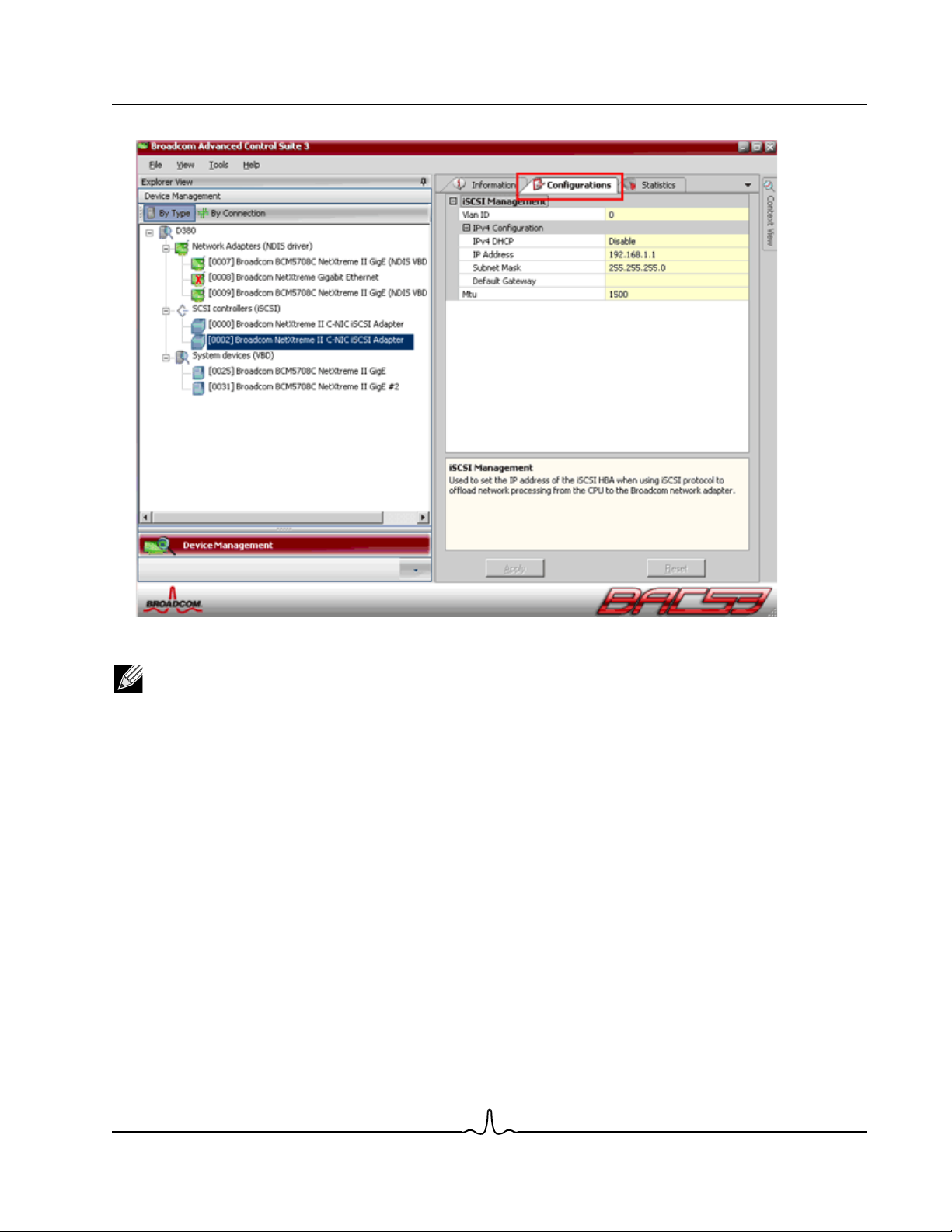
User Guide NetXtreme II
January 2010
3. Select the Configuration tab.
4. DHCP is the default for IP address assignment, but this can be changed to static IP address assignment, if this is the
preferred method of IP address assignment.
NOTE: The IP address assignment method cannot be changed if the adapter was used for boot.
Broadcom Corporation
Document ENGSRVT52-CDUM100-R iSCSI Offload Page 93
Page 94

NetXtreme II User Guide
January 2010
5. Select Apply and close BACS.
Broadcom Corporation
Page 94 iSCSI Offload Document ENGSRVT52-CDUM100-R
Page 95

User Guide NetXtreme II
January 2010
Configure Microsoft Initiator to Use Broadcom’s iSCSI Offload
Now that the IP address has been configured for the iSCSI adapter, you need to use Microsoft Initiator to configure and add
a connection to the iSCSI target using Broadcom iSCSI adapter. See Microsoft’s user guide for more details on Microsoft
Initiator.
1. Open Microsoft Initiator.
2. Configure the initiator IQN name according to your setup. To change, click on Change.
3. Enter the initiator IQN name.
Broadcom Corporation
Document ENGSRVT52-CDUM100-R iSCSI Offload Page 95
Page 96

NetXtreme II User Guide
January 2010
4. Select the Discovery tab and click Add to add a target portal.
5. Enter the IP address of the target and click Advanced.
Broadcom Corporation
Page 96 iSCSI Offload Document ENGSRVT52-CDUM100-R
Page 97

User Guide NetXtreme II
January 2010
6. From the General tab, select Broadcom NetXtreme II C-NIC iSCSI Adapter from Local adapter.
Broadcom Corporation
Document ENGSRVT52-CDUM100-R iSCSI Offload Page 97
Page 98

NetXtreme II User Guide
January 2010
7. Select the IP address for the adapter from Source IP.
Broadcom Corporation
Page 98 iSCSI Offload Document ENGSRVT52-CDUM100-R
Page 99

User Guide NetXtreme II
January 2010
8. Click OK to close Advanced setting and then OK to add the target portal.
Broadcom Corporation
Document ENGSRVT52-CDUM100-R iSCSI Offload Page 99
Page 100
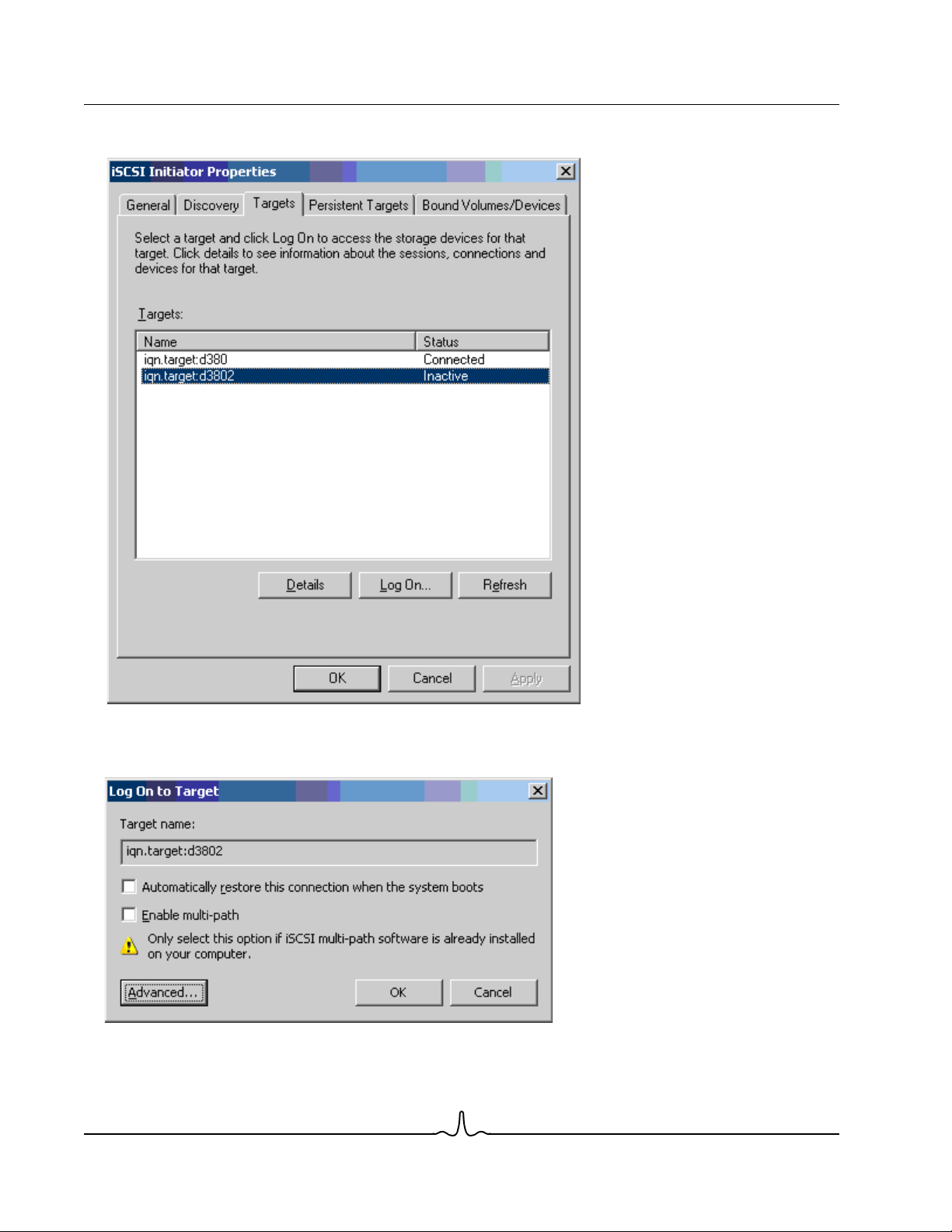
NetXtreme II User Guide
January 2010
9. From the Targets tab, select the target and click Log On to log into your iSCSI target using the Broadcom iSCSI adapter.
10. Click on Advanced.
Broadcom Corporation
Page 100 iSCSI Offload Document ENGSRVT52-CDUM100-R
 Loading...