

Page 1

Control Node and Network Switch Cabling
Example
This document provides background information and detailed procedures for cabling dual
Cassatt Active Response control nodes and network switches and for configuring those
network switches. These procedures are an example of one way you could cable the control
nodes and configure the switches. If your site setup differs, use this document as a guideline.
Cabling control node and switch hardware
Prerequisites
This example assumes you have completed the following tasks:
• You have obtained all the required hardware.
• You have determined your network address strategy and allocated the required IP
addresses according to network requirements of
•
You have configured your gateway or gateways using the static IP addresses you allocated
from the Cassatt network.
Cassatt Active Response.
See the
Cassatt Active Response.
Info Central
site for detailed information on calculating network addresses for
Port numbering
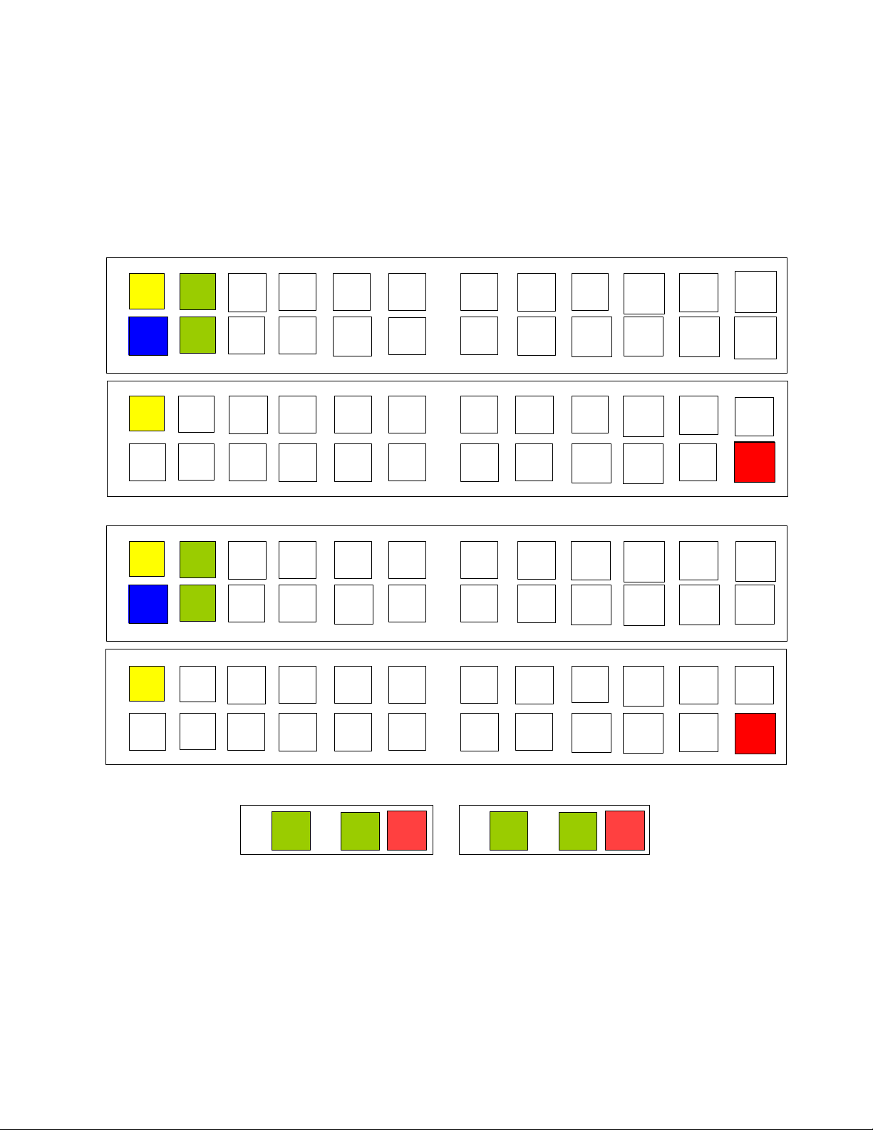
You must understand the switch and control node port numbering to cable the Cassatt Active
Response environment’s hardware components together correctly. Figure 1 assumes use of a
Cisco switch and shows switch ports, the switch module ports, and the control node ports. As
an example, this document assumes four network switches intended for use with 24
CASSATT ACTIVE RESPONSE CONTROL NODE AND NETWORK SWITCH CABLING EXAMPLE 16
Page 2
C2-1
C2-P
C2-2
Gb 2
Gb1
Control node 2
C1-1
N9-1N5-1
ISL-1
N21- 1
N12- P
N3-P
C2-1
N11-1
N7-1N3-1
GW-1 N16- PN23-1
N8-P
1
2
3
4
5
Switch stack 1
N20- P
N13-1
N15-1
N17-1
N19-1
N10-1N6-1
ISL-2
N11- P
N1-P
N12- 1N8-1N4-1
N15-P
N23-P
N7-P C2-P
N19- P
N14-1
N16-1
N18-1
N20- 1
Switch stack 2
Control node 1
Switch 1
Switch 2
Switch 3Switch 4
79
11 13 15
17
19 21
23
6
8
10 12
14
16 18
20
22 24
1
3
5
7
9
11 13 15
17 19
21
23
2
46
810
12 14 16 18 20 22
24
C1-2
N9-2N5-2
ISL-1
N21- 2
N10- P
N4-P
C2-2
N11-2
N7-2N3-2
GW-2
N22-P
N23-2
N6-P
1
2
3
4
5
N18- P
N13-2
N15-2
N17-2
N19-2
N10-2N6-2
ISL-2
N9-P N2-P
N14- 2N10-2N4-2
N13-P
N21-P
C1-P
N17- P
N14-2
N16-2
N18-2
N20- 2
79
11 13 15 17
19 21
23
6
8
10 12
14
16 18
20
22 24
1
3
5
7
9
11 13 15
17 19
21
23
2
46
810
12 14 16 18 20 22
24
C1-1
C1-P
C1-2
Gb 2
Gb1
N14- P
N5-P
N1-1
N1-2
N2-1
N2-2
N22-1
N22-2
Legend:
Blue = Gateway (GW) N
n-1 = Application node NIC
Yellow = Cisco interswitch link (ISL) N
n-2 = Application node NIC
Green = Control node (C) N
n-P = Application node remote management controller
Red = Remote management controller
application nodes. Note that detailed instructions for adding application nodes are in a
separate document, which you should consult when you are ready to cable application nodes
into your Cassatt Active Response environment. (Figure 1 highlights the control node and
network switches, but also suggests application node cabling.)
Figure 1 Switch Panel and Control Node Cabling
CASSATT ACTIVE RESPONSE CONTROL NODE AND NETWORK SWITCH CABLING EXAMPLE 17
Page 3

Table 1 shows how each port is used on the switch and control node.
Table 1 Description of Panel and Main Board Notation
Notation Description
ISL-1 Used to create the first half of interswitch link (ISL)
connection between the two Cisco switches.
ISL-2 Used to create the second half of the ISL connection
between the two Cisco switches.
GW-1 Used to create the first connection from the Cisco switch
to the gateway.
GW-2 Used to create the second connection from the Cisco
switch to the gateway.
C1-1 Used to connect the first control node’s first onboard
Gigabit Ethernet connection (Gb 1) into the Cassatt Active
Response environment through the designated switch port.
C1-2 Used to connect the first control node’s first onboard
Gigabit Ethernet connection (Gb 2) into the Cassatt Active
Response environment through the designated switch port.
C2-1 Used to connect the second control node’s second onboard
Gigabit Ethernet connection (Gb 2) into the Cassatt Active
Response environment through the designated switch port.
C2-2 Used to connect the second control node’s second onboard
Gigabit Ethernet connection (Gb 2) into the Cassatt Active
Response environment through the designated switch port.
C1-P Used to connect the first control node remote management
controller into the Cassatt Active Response environment.
C2-P Used to connect the second control node remote
management controller into the Cassatt Active Response
environment.
N1-1 through N23-1 Used to connect application nodes into the Cassatt Active
Response environment.
N2-1 through N23-2 Used to connect application nodes into the Cassatt Active
Response environment.
CASSATT ACTIVE RESPONSE CONTROL NODE AND NETWORK SWITCH CABLING EXAMPLE 18
Page 4
What about connecting application nodes?
Switch 1Switch 2
Switch 3
Switch 4
Rear panels
Stack2Stack1
Stack1 Stack2 Stack1 Stack2
Stack1 Stack2
Remaining switch ports can be used to connect application nodes and their remote management controllers
into the Cassatt Active Response environment. In general, distribute the connections evenly between the
switches and the application nodes (both the application node NICs and their associated remote management
controller NICs) For more information,
up application nodes.
Racking and cabling guidelines
To cable your control nodes to the network switches according to Figure 1, follow these
steps. Remember that this sample configuration uses four network switches, so use these
instructions as a guideline for your own configuration.
1. Rack all switches and control node hardware according to the vendor’s documentation
and/or the site policy. For lack of any other policy, rack the heaviest of the following
pieces of equipment on the bottom:
• Cisco switches
• Power distribution units (PDUs)
• Control nodes
• Application nodes
see the
Info Central
site for detailed information on setting
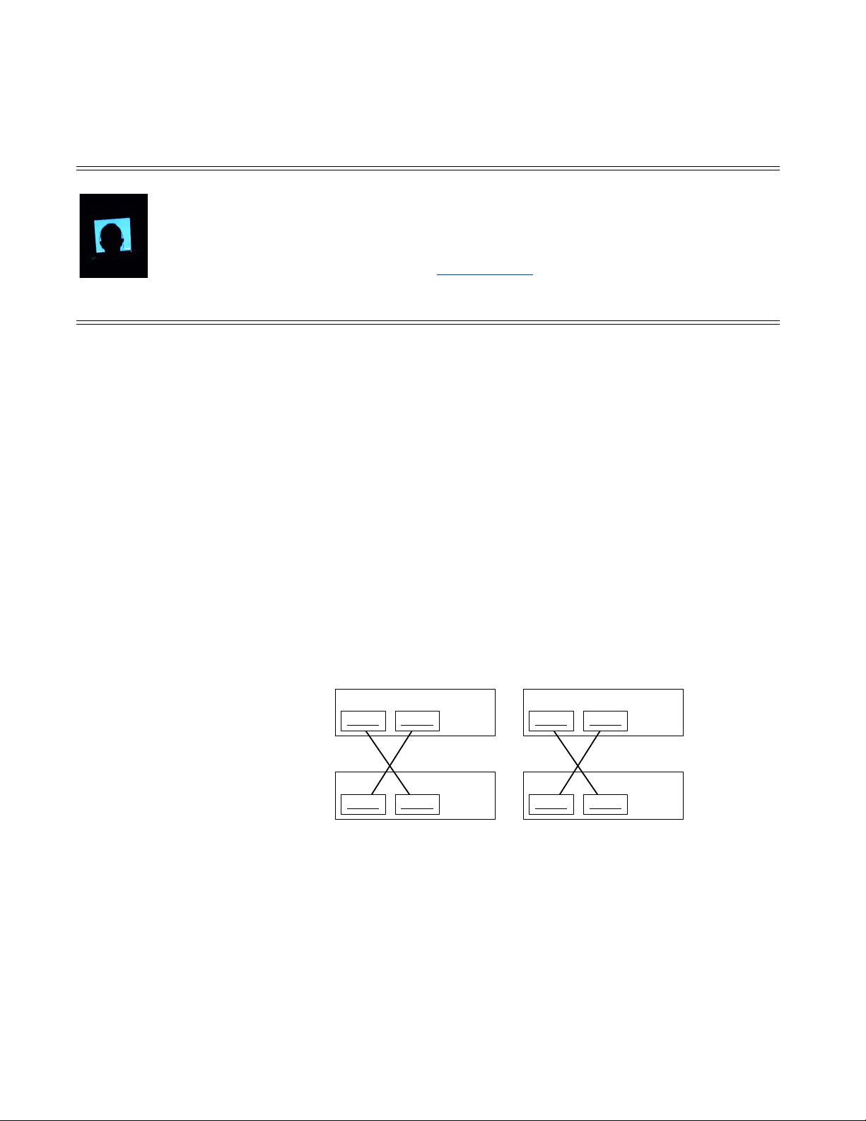
2. Follow the Cisco switch hardware installation instructions and use the StackWise cables
to cable the four switches into two sets of switch stacks, as shown in Figure 2. Once the
two 24-port switches have been stacked, they behave as a single logical 48-port switch.
Figure 2 Stacked Switch Cabling
CASSATT ACTIVE RESPONSE CONTROL NODE AND NETWORK SWITCH CABLING EXAMPLE 19
Page 5

3. Connect the control nodes to the shared storage hardware, as follows:
If... Then...
a SAN is used for shared storage • Insert a Host Bus Adapter (HBA) into each control
node.
• Connect one end of the fiber cable to the HBA and the
other end to your site's SAN.
a NAS and dual-ported disk is used
for shared storage
• Insert the connectivity card required for the dualported disk into each control node.
• Connect the other end of each card to the dual-ported
disk.
4. Using crossover cables, create an interswitch link (ISL) between the two Cisco 3750
switches. The recommended configuration uses two ISL connections between the Cisco
switches for increased bandwidth and redundancy. As suggested in Figure 1, create the
first half of the ISL between the stacked switches, as follows.
• Connect port 1 on switch 1 to port 1 on switch 3.
5. Then create the second half of the ISL between the stacked switches as follows:
• Connect port 1 on switch 2 to port 1 on switch 4.
• Connect port 2 on switch 1 to the edge router to make the first gateway connection.
• Connect port 2 on switch 3 to the edge router to make the second gateway
connection.
6. Using the Cisco switches and control node port information in Figure 1, connect the
control nodes to the switches using category 5 or 6 Ethernet cables. The recommended
configuration uses dual Ethernet connections to each control node for redundancy. Do
this as follows:
• From control node 1's back panel:
- Connect Gb1 port 1, C1-1, into port 3 on switch 1
- Connect Gb2 port 2, C1-2, into port 3 on switch 3
- Connect the remote management controller port, C1-P, into port 24 on switch 4
• From control node 2's back panel:
- Connect Gb1 port 1, C2-1, into port 4 on switch 1
- Connect Gb2 port 2, C2-2, into port 4 on switch 3
- Connect the remote management controller port, C2-P, into port 24 on switch 2
If you are cabling application nodes, you can follow the diagram in Figure 1. For more
application-node specific cabling instructions, see the
CASSATT ACTIVE RESPONSE CONTROL NODE AND NETWORK SWITCH CABLING EXAMPLE 20
Info Central
site.
Page 6

Configuring the switches
After you have racked and cabled the control nodes and switches, you need to configure both
Cisco switch stacks. If you are using another of the Cassatt recommended switches (see the
Info Central
as a guideline.
Do not configure network switches to enforce a maximum number of Ethernet addresses
learned on an interface. For example, on Cisco switches, do not use “switchport portsecurity.” Doing so may prevent
discovery process.
Connecting the switch to a terminal server
To configure the first Cisco Catalyst 3750 Series switch stack to a Lantronix terminal server,
do the following. If you are using another terminal server, use this Lantronix configuration as
a guideline.
1. Unplug the network switches.
1. Connect the switch in a stack to a terminal server.
It may be convenient to connect all switch consoles to the terminal server to avoid the
need to move cables if a switch fails. Follow the switch connector and cable specifications
in the Catalyst 3750 Switch Hardware Installation Guide to determine what type of cable is
needed when connecting the switch for configuration. The RJ-45-to-DB-9 adapter cable
that comes with the switch for this connection was not used for the reference
configuration testing.
site for recommended switch hardware), use this Cisco switch configuration
Cassatt Active Response from inventorying VMs during the
Cassatt tested the switch with an RJ-45 cable with reversed pins connected to a Lantronix
ETS terminal server. The following Lantronix port settings were used:
Char Size/Stop Bits: 8/1 Input Speed: 9600
Flow Ctrl: None Output Speed: 9600
Parity: None Modem Control: None
Access: Remote Local Switch: None
Backward: None Port Name: Port_10
Break Ctrl: Local Session Limit: 4
Forward: None Terminal Type: Soft()
Preferred Services: (Lat)
(Telnet)
Authorized Groups : 0
(Current) Groups : 0
Characteristics: Broadcast Loss Notify Verify Remote Conf
Telnet Pad
2. Log into the terminal server.
3. Connect to the Cisco switch via the terminal server console.
CASSATT ACTIVE RESPONSE CONTROL NODE AND NETWORK SWITCH CABLING EXAMPLE 21
Page 7

4. Plug in the Cisco switches in a stack.
5. Many boot-up and self-test messages will scroll on the console monitor. When the
process is completed, use the following table to determine your next step:
If the following displays at the
prompt...
Continue with configuration
dialog? [yes/no]:
Press RETURN to get started!
Then...
The switch stack is in the factory default state; go to
step 1 in
configuring the switch.
The switch stack has already been configured and the
switch stack must be restored to the factory settings;
go to step 1 in
page 22.
Setting switch options on page 24 to continue
Restoring the factory default settings on
Restoring the factory default settings
To reset the switches in a switch stack to the factory defaults, you must delete the startup
configuration and virtual local area network (VLAN) database files. Execute the following
privileged command sequence to restore the Cisco Catalyst 3750 Series switch configuration
to the original factory setting:
1. Delete the startup configuration and configuration files, as follows:
At this prompt... Enter... Notes
sw01> enable
sw01# write erase
Erasing the nvram filesystem will remove all configuration
files! Continue? [confirm]y[OK]
Erase of nvram: complete
00:06:43: %SYS-7-NV_BLOCK_INIT: Initalized the geometry of
nvram.
2. Delete the VLAN database, as follows:
Displays the following output:
At this prompt... Enter... Notes
sw01# delete flash:vlan.dat
Delete filename [vlan.dat]?
Delete flash:vlan.dat? [confirm] y
CASSATT ACTIVE RESPONSE CONTROL NODE AND NETWORK SWITCH CABLING EXAMPLE 22
Select Enter
Page 8

3. If the switch was used previously in a switch stack, and is now in a different switch stack,
it may have a switch number other than 1 and 2. To determine if the switch number must
be reset, display the switch configuration as follows:
At this prompt... Enter... Notes
sw01# show switch
Switch# Role Mac Address Priority State
-------------------------------------------------------*1 Master 0011.bb7e.9480 1 Ready
2 Slave 0011.bb25.ce80 1 Ready
Switch# Role Mac Address Priority State
-------------------------------------------------------*1 Master 0011.bb7e.9480 1 Ready
2 Slave 0011.bb25.ce80 1 Ready
If... Then...
If a switch number other than 1 and 2 is
indicated in the output
If the switch number is 1 and 2 Go to step 7.
Go to step 4.
Displays the following output:
4. Enter the configuration mode, as follows:
At this prompt... Enter... Notes
Switch# configure terminal
Enter configuration commands, one per line. End with CNTL/Z.
Displays the following output:
5. Renumber the switch, as follows:
Current
Current
At this prompt... Enter... Notes
sw01# switch 3 renumber 2
WARNING: Changing the switch number may result in lost
or changed configuration for that switch!
At this prompt... Enter... Notes
Do you want to continue?[confirm] y
CASSATT ACTIVE RESPONSE CONTROL NODE AND NETWORK SWITCH CABLING EXAMPLE 23
Replace 3 with the number
displayed for your switch.
Replace 2 with the number that
is missing.
Displays the following output:
Displays the following output:
Page 9

Changing Switch Number 3 to Switch Number 2 New Switch Number
will be effective after next reboot
6. Exit the configuration mode, as follows:
At this prompt... Enter... Notes
sw01# exit
7. Halt and perform a cold restart, as follows:
At this prompt... Enter... Notes
sw01> reload
System configuration has been modified.
Save? [yes/no]:
Proceed with reload? [confirm] y
00:08:23: %SYS-5-RELOAD: Reload requested
Base ethernet MAC Address: 00:11:bb:7e:94:80
Xmodem file system is available.
The password-recovery mechanism is enabled.
Initializing Flash...
flashfs[0]: 79 files, 4 directories
flashfs[0]: 0 orphaned files, 0 orphaned directories
flashfs[0]: Total bytes: 15998976
flashfs[0]: Bytes used: 6457856
flashfs[0]: Bytes available: 9541120
flashfs[0]: flashfs fsck took 8 seconds.
...done Initializing Flash.
Boot Sector Filesystem (bs) installed, fsid: 3
done.
...
Press RETURN to get started!
Proceed to step 1 in Setting switch options on page 24 to continue the switch configuration
procedure.
Setting switch options
no
Displays the following output:
This procedure provides the minimal configuration required to support the reference system.
Configure the first switch stack as follows:
1. Select the
At this prompt... Enter... Notes
--- System Configuration Dialog ---
would you like to enter the initial configuration
dialog? [yes/no]:
CASSATT ACTIVE RESPONSE CONTROL NODE AND NETWORK SWITCH CABLING EXAMPLE 24
Enter
key to get started. Skip the initial configuration, as follows:
no
Page 10

2. Enter the privileged mode, as follows:
At this prompt... Enter... Notes
Switch> enable
3. Enter the configuration mode, as follows:
At this prompt... Enter... Notes
Switch# configure terminal
Displays the following output:
Enter configuration commands, one per line. End with CNTL/Z.
4. Turn the messages off, as follows:
At this prompt... Enter... Notes
Switch(config)# no logging console
Some of the switch configuration
commands can produce many
messages that are logged to the
console, which is often
inconvenient.
5. Turn off all interfaces on the first switch, as follows:
At this prompt... Enter... Notes
Switch(config)# interface range GigabitEthernet 1/0/1 – 24
Switch(config-ifrange)#
Switch(config-ifrange)#
shutdown
exit
This step is done to prevent
network loops from forming
because the configuration is only
partially enabled at this time.
6. Turn off all the interfaces on the second switch, as follows:
At this prompt... Enter... Notes
Switch(config)# interface range GigabitEthernet 2/0/1 – 24
Switch(config-ifrange)#
Switch(config-ifrange)#
shutdown
exit
CASSATT ACTIVE RESPONSE CONTROL NODE AND NETWORK SWITCH CABLING EXAMPLE 25
This is done for the same reason as
stated in the previous step.
Page 11

7. Set the host name of the switch stack, as follows:
At this prompt... Enter... Notes
Switch(config)# hostname sw01
Use your site-specific name instead
of sw01 used as an example; each
switch should have a unique name.
8. Set the switch stack’s enable password, as follows:
At this prompt... Enter... Notes
sw01(config)# enable secret system
Use your site-specific password
instead of the system password used
as an example.
9. Turn off the VLAN trunking protocol (VTP), as follows:
At this prompt... Enter... Notes
sw01(config)# vtp mode transparent
sw01(config)#
Setting device to VTP TRANSPARENT mode.
10. Enable the
At this prompt... Enter... Notes
sw01(config)# spanning-tree portfast bpduguard default
portfast bpduguard
feature, as follows:
Displays the following output:
Enabling this feature protects
against cabling errors. If a spanning
tree packet does arrive on a port
that has this feature enabled, the
port is disabled.
CASSATT ACTIVE RESPONSE CONTROL NODE AND NETWORK SWITCH CABLING EXAMPLE 26
Page 12

11. Aggregate the two physical links between the two Cisco switches in the stack into a single
logical link, as follows:
At this prompt... Enter... Notes
sw01(config)# interface GigabitEthernet1/0/1
The single logical link provides
both reliability and higher capacity.
When possible, the two links of the
port channel should be on
different switches to provide
reliability in case a complete switch
goes down. In this reference
configuration, stacked switches are
used, so both ports are not on the
same switch. The manual
configuration of the port channel
is required when the interfaces are
on different switches.
sw01(config-if)# channel-group 1 mode on
Displays the following output:
Creating a port-channel interface Port-channel 1
At this prompt... Enter... Notes
sw01(config-if)# exit
sw01(config-if)# interface GigabitEthernet2/0/1
sw01(config-if)# channel-group 1 mode on
sw01(config-if)# exit
12. Set the interface connection to the router, as follows:
At this prompt... Enter... Notes
sw01(config)# interface GigabitEthernet1/0/2
sw01(config)# switchport mode access
sw01(config-if)# exit
This connection is set to access
mode because no VLAN traffic
should be sent over it.
CASSATT ACTIVE RESPONSE CONTROL NODE AND NETWORK SWITCH CABLING EXAMPLE 27
Page 13

13. Set the remaining interfaces, which are identical, as follows.
If the switches connect to a gateway device through another switch or a device that
participates in spanning tree protocol, do not set
spanning tree portfast
that device.
At this prompt... Enter... Notes
for the link to
sw01(config)# interface range GigabitEthernet 1/0/3 – 24
sw01(config-if-range)# spanning-tree portfast
%Warning: portfast should only be enabled on ports connected to
a single host. Connecting hubs, concentrators, switches,
bridges, etc... to this interface when portfast is enabled, can
cause temporary bridging loops.
Use with CAUTION
%Portfast will be configured in 22 interfaces due to the range
command but will only have effect when the interfaces are in a
non-trunking mode.
Setting the portfast option means
that the port starts forwarding
packets immediately instead of
waiting for spanning tree protocol
packets. This allows for less
dropped packets when a switch
first is brought online. This
explanation assumes that none of
the interfaces are running
spanning tree. All spanning treeto-spanning tree switches must not
have spanning-tree portfast
enabled. If they do have it enabled,
the interface is automatically
disabled upon receipt of a
spanning tree packet.
Displays the following output:
At this prompt... Enter... Notes
sw01(config-if-range)# switchport mode access
sw01(config-if-range)# exit
sw01(config)# interface range GigabitEthernet 2/0/2 – 24
sw01(config-if-range)# spanning-tree portfast
Displays the following output:
%Warning: portfast should only be enabled on ports connected to
a single host. Connecting hubs, concentrators, switches,
bridges, etc... to this interface when portfast is enabled, can
cause temporary bridging loops.
Use with CAUTION
CASSATT ACTIVE RESPONSE CONTROL NODE AND NETWORK SWITCH CABLING EXAMPLE 28
Page 14

%Portfast will be configured in 23 interfaces due to the range
command but will only have effect when the interfaces are in a
non-trunking mode
At this prompt... Enter... Notes
sw01(config-if-range)# switchport mode access
sw01(config-if-range)# exit
14. Disable IGMP snooping, as follows:
At this prompt... Enter... Notes
sw01(config)# no ip igmp snooping
IGMP snooping is disabled to resolve communication issues
with the bonded Ethernet interfaces, IGMP snooping, and
multicast. By default, IGMP snooping is globally available on the
switch. With IGMP snooping, multicast packets are forwarded
only to the ports that have joined that multicast group. When
IGMP snooping is disabled, multicast packets are forwarded to
all ports on the switch.
If disabling IGMP snooping impacts network performance, and
if non-Cassatt Active Response applications running on the
Cassatt Active Response system do not use the multicast
functionality, disabling IGMP snooping can be done on the
control nodes only. In this case, do not disable IGMP snooping
on the switch; instead, refer to the
Configuration Guide
control nodes to statically join the multicast group.
to configure the four interfaces on the
Catalyst 3750 Switch Software
15. Turn off the HTTP server, as follows:
At this prompt... Enter... Notes
sw01(config)# no ip http server
The HTTP server is not used and
is turned off as a security
precaution.
16. Set the message of the day, as follows:
At this prompt... Enter... Notes
sw01(config)# banner motd #
Displays the following output; set
the message as required by
your site policy:
Enter TEXT message. End with the character '#'.
*************************************
insert message here
*************************************
#
CASSATT ACTIVE RESPONSE CONTROL NODE AND NETWORK SWITCH CABLING EXAMPLE 29
Page 15

17. Turn all the interfaces back on, as follows:
At this prompt... Enter... Notes
sw01(config)# interface range GigabitEthernet 1/0/1 - 24
sw01(config-if-range)# no shutdown
sw01(config-if-range)# exit
sw01(config)# interface range GigabitEthernet 2/0/1 - 24
sw01(config-if-range)# no shutdown
sw01(config-if-range)# exit
18. Turn logging to the console back on, as follows:
At this prompt... Enter... Notes
sw01(config)# logging console
19. Exit the configuration mode, as follows:
At this prompt... Enter... Notes
sw01(config)# exit
20. Verify the switch configuration, as follows:
At this prompt... Enter... Notes
sw01# show running-config
Displays the following output:
Building configuration...
Current configuration : 3230 bytes
!
Version 12.1
no service pad
service timestamps debug uptime
service timestamps log uptime
no service password-encryption
!
hostname sw01
!
enable secret 5 $1$45RQ$hd1IzO.vm5WKRsLXyZoFx0
!
ip subnet-zero
no ip igmp snooping
!
vtp mode transparent
!
spanning-tree mode pvst
spanning-tree portfast bpduguard default
no spanning-tree optimize bpdu transmission
spanning-tree extend system-id
!
!
CASSATT ACTIVE RESPONSE CONTROL NODE AND NETWORK SWITCH CABLING EXAMPLE 30
Page 16

interface Port-channel1
no ip address
!
interface GigabitEthernet1/0/1
no ip address
no mdix auto
channel-group 1 mode on
!
interface GigabitEthernet1/0/2
switchport mode access
no ip address
no mdix auto
!
interface GigabitEthernet1/0/3
switchport mode access
no ip address
no mdix auto
spanning-tree portfast
!
interface GigabitEthernet1/0/4
switchport mode access
no ip address
no mdix auto
spanning-tree portfast
!
interface GigabitEthernet1/0/5
switchport mode access
no ip address
no mdix auto
spanning-tree portfast
!
interface GigabitEthernet1/0/6
switchport mode access
no ip address
no mdix auto
spanning-tree portfast
!
...
<ports 7 through 23 output on the first switch in the switch stack should be the same as shown above for
interface GigabitEthernet1/0/6>
...
interface GigabitEthernet1/0/24
switchport mode access
no ip address
no mdix auto
spanning-tree portfast
!
interface GigabitEthernet2/0/1
no ip address
no mdix auto
channel-group 1 mode on
!
interface GigabitEthernet2/0/2
switchport mode access
no ip address
no mdix auto
spanning-tree portfast
CASSATT ACTIVE RESPONSE CONTROL NODE AND NETWORK SWITCH CABLING EXAMPLE 31
Page 17

!
interface GigabitEthernet2/0/3
switchport mode access
no ip address
no mdix auto
spanning-tree portfast
!
interface GigabitEthernet2/0/4
switchport mode access
no ip address
no mdix auto
spanning-tree portfast
!
interface GigabitEthernet2/0/5
switchport mode access
no ip address
no mdix auto
spanning-tree portfast
!
interface GigabitEthernet2/0/6
switchport mode access
no ip address
no mdix auto
spanning-tree portfast
!
...
<ports 7 through 23 output on the first switch in the switch stack should be the same as shown above for
interface GigabitEthernet2/0/6>
...
interface GigabitEthernet2/0/24
switchport mode access
no ip address
no mdix auto
spanning-tree portfast
!
interface Vlan1
no ip address
shutdown
!
ip classless
no ip http server
!
banner motd ^C
*************************************
XXX
*************************************
^C
!
line con 0
line vty 5 15
!
end
CASSATT ACTIVE RESPONSE CONTROL NODE AND NETWORK SWITCH CABLING EXAMPLE 32
Page 18

21. Save the configuration across a reboot of the switch, as follows:
At this prompt... Enter... Notes
sw01# copy running-config startup-config
Destination filename [startup-config]?
Building configuration...
[OK]
sw01#
22. Configure the second Cisco switch stack by repeating step 1 in Connecting the switch to a
terminal server on page 21 through step 21 in Setting switch options on page 24.
When you have completed configuring all switch stacks, plug them in.
Displays the following output:
CASSATT ACTIVE RESPONSE CONTROL NODE AND NETWORK SWITCH CABLING EXAMPLE 33
 Loading...