

Cisco Network Convergence System 6000 Series, NCS 6008 Unpacking, Moving, And Securing Manual
Page 1

Cisco Network Convergence System
6000 Series Routers
Unpacking, Moving, and Securing Guide
September 2013
Cisco Systems, Inc.
www.cisco.com
Cisco has more than 200 offices worldwide.
Addresses, phone numbers, and fax numbers
are listed on the Cisco website at
www.cisco.com/go/offices.
Text Part Number: OL-29233-01
Page 2

THE SPECIFICATIONS AND INFORMATION REGARDING THE PRODUCTS IN THIS MANUAL ARE SUBJECT TO CHANGE WITHOUT NOTICE. ALL
STATEMENTS, INFORMATION, AND RECOMMENDATIONS IN THIS MANUAL ARE BELIEVED TO BE ACCURATE BUT ARE PRESENTED WITHOUT
WARRANTY OF ANY KIND, EXPRESS OR IMPLIED. USERS MUST TAKE FULL RESPONSIBILITY FOR THEIR APPLICATION OF ANY PRODUCTS.
THE SOFTWARE LICENSE AND LIMITED WARRANTY FOR THE ACCOMPANYING PRODUCT ARE SET FORTH IN THE INFORMATION PACKET THAT
SHIPPED WITH THE PRODUCT AND ARE INCORPORATED HEREIN BY THIS REFERENCE. IF YOU ARE UNABLE TO LOCATE THE SOFTWARE LICENSE
OR LIMITED WARRANTY, CONTACT YOUR CISCO REPRESENTATIVE FOR A COPY.
The following information is for FCC compliance of Class A devices: This equipment has been tested and found to comply with the limits for a Class A digital device, pursuant
to part 15 of the FCC rules. These limits are designed to provide reasonable protection against harmful interference when the equipment is operated in a commercial
environment. This equipment generates, uses, and can radiate radio-frequency energy and, if not installed and used in accordance with the instruction manual, may cause
harmful interference to radio communications. Operation of this equipment in a residential area is likely to cause harmful interference, in which case users will be required
to correct the interference at their own expense.
The following information is for FCC compliance of Class B devices: This equipment has been tested and found to comply with the limits for a Class B digital device, pursuant
to part 15 of the FCC rules. These limits are designed to provide reasonable protection against harmful interference in a residential installation. This equipment generates,
uses and can radiate radio frequency energy and, if not installed and used in accordance with the instructions, may cause harmful interference to radio communications.
However, there is no guarantee that interference will not occur in a particular installation. If the equipment causes interference to radio or television reception, which can be
determined by turning the equipment off and on, users are encouraged to try to correct the interference by using one or more of the following measures:
• Reorient or relocate the receiving antenna.
• Increase the separation between the equipment and receiver.
• Connect the equipment into an outlet on a circuit different from that to which the receiver is connected.
• Consult the dealer or an experienced radio/TV technician for help.
Modifications to this product not authorized by Cisco could void the FCC approval and negate your authority to operate the product.
The Cisco implementation of TCP header compression is an adaptation of a program developed by the University of California, Berkeley (UCB) as part of UCB’s public
domain version of the UNIX operating system. All rights reserved. Copyright © 1981, Regents of the University of California.
NOTWITHSTANDING ANY OTHER WARRANTY HEREIN, ALL DOCUMENT FILES AND SOFTWARE OF THESE SUPPLIERS ARE PROVIDED “AS IS” WITH
ALL FAULTS. CISCO AND THE ABOVE-NAMED SUPPLIERS DISCLAIM ALL WARRANTIES, EXPRESSED OR IMPLIED, INCLUDING, WITHOUT
LIMITATION, THOSE OF MERCHANTABILITY, FITNESS FOR A PARTICULAR PURPOSE AND NONINFRINGEMENT OR ARISING FROM A COURSE OF
DEALING, USAGE, OR TRADE PRACTICE.
IN NO EVENT SHALL CISCO OR ITS SUPPLIERS BE LIABLE FOR ANY INDIRECT, SPECIAL, CONSEQUENTIAL, OR INCIDENTAL DAMAGES, INCLUDING,
WITHOUT LIMITATION, LOST PROFITS OR LOSS OR DAMAGE TO DATA ARISING OUT OF THE USE OR INABILITY TO USE THIS MANUAL, EVEN IF CISCO
OR ITS SUPPLIERS HAVE BEEN ADVISED OF THE POSSIBILITY OF SUCH DAMAGES.
Cisco and the Cisco logo are trademarks or registered trademarks of Cisco and/or its affiliates in the U.S. and other countries. To view a list of Cisco trademarks, go to this
URL: www.cisco.com/go/trademarks. Third-party trademarks mentioned are the property of their respective owners. The use of the word partner does not imply a partnership
relationship between Cisco and any other company. (1110R)
Any Internet Protocol (IP) addresses and phone numbers used in this document are not intended to be actual addresses and phone numbers. Any examples, command display
output, network topology diagrams, and other figures included in the document are shown for illustrative purposes only. Any use of actual IP addresses or phone numbers in
illustrative content is unintentional and coincidental.
Cisco Network Convergence System 6000 Series Routers Unpacking, Moving, and Securing Guide
© 2013 Cisco Systems, Inc. All rights reserved.
Page 3

CONTENTS
Audience 1-v
Conventions v
Related Documentation 1-vii
Changes to This Document 1-vii
Obtaining Additional Information and Support 1-viii
CHAPTER
CHAPTER
1 Chassis Packaging 1-1
Chassis Specifications 1-2
Safety Guidelines 1-2
Preventing Electrostatic Discharge 1-3
Site Preparation 1-3
System Installation Templates 1-3
Dolly Specifications 1-4
Unpacking the Dolly 1-5
Required Tools and Equipment 1-5
Steps 1-5
Modifying the Dolly Configuration 1-11
Required Tools and Equipment 1-11
Steps 1-11
2 Required Tools and Equipment 2-1
Steps 2-2
Attaching the Dolly to the Chassis and Removing the Chassis Pallet 2-5
Prerequisites 2-6
Required Tools and Equipment 2-6
Steps 2-7
CHAPTER
3 Important Notice 3-1
Guidelines 3-1
Verifying the Move Path 3-3
Moving the Unpacked Chassis 3-5
Prerequisites 3-5
Steps 3-6
Cisco Network Convergence System 6000 Series Routers Unpacking, Moving, and Securing Guide
OL-29233-01
iii
Page 4

Contents
CHAPTER
4 Prerequisites 4-1
Required Tools and Equipment 4-1
Steps 4-2
Unpacking Chassis Components 4-3
Steps 4-3
Component Return Information 4-4
Cisco Network Convergence System 6000 Series Routers Unpacking, Moving, and Securing Guide
iv
OL-29233-01
Page 5

Preface
This document provides instructions for unpacking a Cisco NCS 6008 chassis and its components,
attaching a dolly, moving the chassis, and securing the chassis to the floor. The Cisco NCS 6008 chassis
is a product in the Cisco Network Convergence System 6000 Series family. The companion document to
this guide is Cisco Network Convergence System 6000 Series Routers Site Planning Guide, which
describes how to plan and prepare your site facilities for chassis installation.
Audience
This document is intended for those who unpack the Cisco NCS 6008 chassis and Cisco installation
partners who are responsible for moving and securing the Cisco NCS 6008 chassis. No additional
knowledge of routing or the Cisco IOS XR software is assumed.
Conventions
This document uses the following conventions:
Convention Indication
bold font Commands and keywords and user-entered text appear in bold font.
italic font Document titles, new or emphasized terms, and arguments for which you supply
values are in italic font.
[ ] Elements in square brackets are optional.
{x | y | z } Required alternative keywords are grouped in braces and separated by
vertical bars.
[ x | y | z ] Optional alternative keywords are grouped in brackets and separated by
vertical bars.
string A nonquoted set of characters. Do not use quotation marks around the string or
the string will include the quotation marks.
courier font Terminal sessions and information the system displays appear in courier font.
< > Nonprinting characters such as passwords are in angle brackets.
[ ] Default responses to system prompts are in square brackets.
!, # An exclamation point (!) or a pound sign (#) at the beginning of a line of code
indicates a comment line.
Cisco Network Convergence System 6000 Series Routers Unpacking, Moving, and Securing Guide
OL-29233-01
v
Page 6
Audience
Note Means reader take note. Notes contain helpful suggestions or references to material not covered in the
manual.
Tip Means the following information will help you solve a problem. The tips information might not be
troubleshooting or even an action, but could be useful information, similar to a Timesaver.
Caution Means reader be careful. In this situation, you might perform an action that could result in equipment
damage or loss of data.
Timesaver Means the described action saves time. You can save time by performing the action described in
the paragraph.
Warning
Warning
IMPORTANT SAFETY INSTRUCTIONS
This warning symbol means danger. You are in a situation that could cause bodily injury. Before you
work on any equipment, be aware of the hazards involved with electrical circuitry and be familiar
with standard practices for preventing accidents. Use the statement number provided at the end of
each warning to locate its translation in the translated safety warnings that accompanied this device.
SAVE THESE INSTRUCTIONS
Statements using this symbol are provided for additional information and to comply with regulatory
and customer requirements.
Cisco Network Convergence System 6000 Series Routers Unpacking, Moving, and Securing Guide
vi
OL-29233-01
Page 7
Related Documentation
For complete planning, installation, and configuration information, see the following documents:
• Cisco Network Convergence System 6000 Series Routers Site Planning Guide
• Cisco Network Convergence System 6000 Series Routers Hardware Installation Guide
• Regulatory Compliance and Safety Information for the Cisco Network Convergence System 6000
Series Routers
Changes to This Document
Table 1 lists the technical changes made to this document since it was first created.
Table 1 Changes to This Document
Revision Date Change Summary
OL-29233-01 September 2013 Initial release of this document. This document introduces
Related Documentation
the Cisco NCS 6008 8-Slot Line Card Chassis.
Cisco Network Convergence System 6000 Series Routers Unpacking, Moving, and Securing Guide
OL-29233-01
vii
Page 8

Obtaining Additional Information and Support
Obtaining Additional Information and Support
For information on obtaining documentation, submitting a service request to obtain support, and
gathering additional information, see the monthly What’s New in Cisco Product Documentation, which
also lists all new and revised Cisco technical documentation:
http://www.cisco.com/en/US/docs/general/whatsnew/whatsnew.html
Subscribe to the What’s New in Cisco Product Documentation as a Really Simple Syndication (RSS) feed,
and set content to be delivered directly to your desktop using a reader application. The RSS feeds are a free
service, and Cisco currently supports RSS version 2.0.
Cisco Network Convergence System 6000 Series Routers Unpacking, Moving, and Securing Guide
viii
OL-29233-01
Page 9

CHAP T E R
1
Overview
The Cisco NCS 6008 chassis is a mechanical enclosure that contains a chassis midplane and packet
interfaces on line cards cross-connected to each other through a switch fabric. The chassis has eight slots
at the front for Line Cards (LCs), two slots at the rear for Route Processor (RP) cards, and six slots at
the rear for Fabric Cards (FCs).
The Cisco NCS 6008 chassis has an integrated rack and does not require an external rack. It is bolted to
the facility floor. It contains its own power and cooling systems. Power systems are available using AC
or DC power.
This chapter provides information about the Cisco NCS 6008 chassis before you unpack it and transport
it to the final installation location.
• Chassis Packaging, page 1-1
• Chassis Specifications, page 1-2
• Safety Guidelines, page 1-2
• Site Preparation, page 1-3
• Dolly Specifications, page 1-4
Chassis Packaging
Depending on the number of options that you ordered, the Cisco NCS 6008 chassis arrives packaged in
several shipping crates and pallets. The chassis is shipped on a pallet by itself and arrives inside a
polyethylene bag enclosed in a plywood box, held in place by steel clips. Other system components are
shipped in separate crates and can arrive at the final chassis site at different times.
For complete details on the contents of your shipment, see the inventory and parts identification label on
the crate. The total number of pallets depend on the details of the options that you ordered, with each
package containing a label that describes the contents.
Note The following list is only a sample of what a Cisco NCS 6008 chassis shipment contains. For complete
details on the contents of each pallet, see the shipping and parts identification label on the pallet or the
shipping manifest.
• Dolly pallet—Contains two dolly units in the 90-degree position (Figure 1-3).
• Chassis pallet—Contains the chassis itself encased in a polyethylene bag and covered with a wooden
packing crate held together with metal brackets. The chassis is the first shipping box to be unpacked
and transported to its final installation location.
Cisco Network Convergence System 6000 Series Routers Unpacking, Moving, and Securing Guide
OL-29233-01
1-1
Page 10

Chassis Specifications
The chassis is shipped with the fan trays and Craft Panel already installed. A plastic panel covers
the rear card cage.
The drill hole template (Cisco product ID NC8-LCC-DRILLTEMP) is attached to the inside of the
shipping crate door.
• Power components pallet—Contains the power components, including the Power Modules (PMs).
• Primary card pallet—Contains the FCs, LCs, and RP cards.
• Cosmetics pallet—Contains the default cosmetic components for the exterior of the chassis. This
pallet will also contain any optional cosmetic components for the exterior of the chassis, if ordered.
Chassis Specifications
Table 1-1 lists the physical specifications (dimensions and weight) for the Cisco NCS 6008 chassis (as
shipped and as installed without packaging).
Table 1-1 Cisco NCS 6008 Chassis Specifications
Physical dimensions (without packaging)
Height 81.0 in. (205.7 cm) as shipped
Width 23.6 in. (59.9 cm)
Depth 39.0 in. (99.1 cm) without doors and other cosmetics
Weight (without packaging)
Chapter 1
84.0 in. (213.4 cm) as installed with the “top cap”
(The top cap in the cosmetics package attaches to the
top of the chassis)
42.0 in. (106.7 cm) with front and rear doors and
standard vertical cable troughs
775 lb (352 kg) chassis as shipped
Safety Guidelines
Caution Before you perform any procedure in this document, review the safety guidelines in this section to avoid
injuring yourself or damaging the equipment.
The following guidelines are for your safety and to protect equipment. Guidelines do not include all
hazards. Be alert.
Note Review the safety warnings listed in Regulatory Compliance and Safety Information for the Cisco NCS
Network Convergence System before installing, configuring, or troubleshooting any installed card.
Cisco Network Convergence System 6000 Series Routers Unpacking, Moving, and Securing Guide
1-2
840 lb (381 kg) chassis in shipping crate with pallet
1450 lb (658 kg) chassis fully loaded with power, fan
trays, cards, and cosmetics
OL-29233-01
Page 11
Chapter 1
• Never attempt to lift an object that might be too heavy for you to lift by yourself.
• Keep the work area clear and dust free during and after installation. Do not allow dirt or debris to
enter into any laser-based components.
• Keep tools and chassis components away from walk areas.
• Do not wear loose clothing, jewelry, and other items that could get caught in the chassis while
working with the chassis and its associated components.
• Use Cisco equipment in accordance with its specifications and product-usage instructions.
• Do not work alone if potentially hazardous conditions exist.
Preventing Electrostatic Discharge
Electrostatic discharge (ESD) damage, which can occur when electronic cards or components are
improperly handled, results in complete or intermittent failures. We recommend use of an
ESD-preventive strap whenever you handle network equipment or one of its components.
Follow these guidelines for preventing ESD damage:
• Always use an ESD-preventive wrist or ankle strap, and ensure that it makes good skin contact.
Connect the equipment end of the connection cord to an ESD connection socket or bare metal
surface on the chassis.
Site Preparation
• Handle a card by its ejector levers, when applicable, or its metal carrier only; avoid touching the
board or connector pins.
• Place a removed card board side up on an antistatic surface or in a static-shielding bag. If you plan
to return the component to the factory, immediately place it in a static-shielding bag.
• Avoid contact between the card and clothing. The wrist strap protects the board from only ESD
voltage on the body: ESD voltage on clothing can still cause damage.
Caution When unpacking and setting parts aside, it is important to set them either in their original antistatic
packaging or on an antistatic mat to avoid ESD damage.
Site Preparation
Before moving the chassis into place and securing it, you must make sure that your site is prepared.
Verify that the securing location provides the recommended space and ensure that you have enough space
available for installation and maintenance of the chassis and its components.
For additional details on making your site ready for the chassis, see the Cisco Network Convergence
System 6000 Series Routers Site Planning Guide.
System Installation Templates
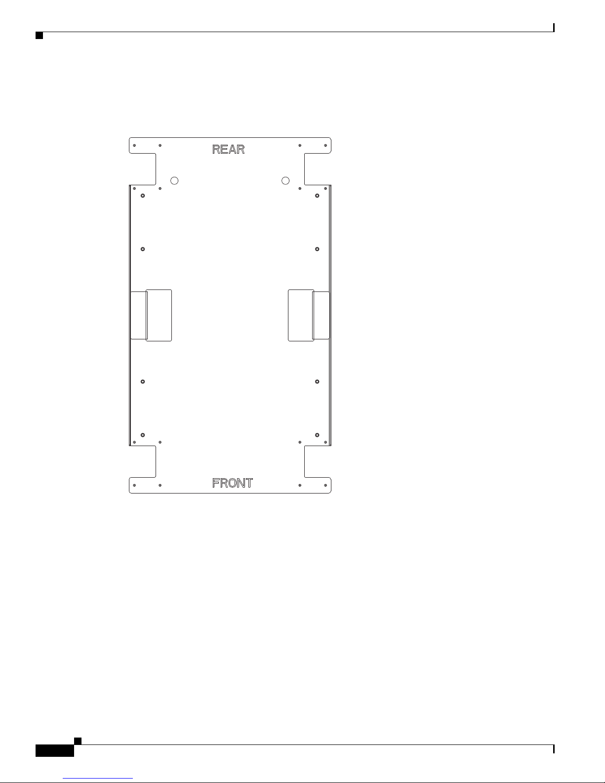
Because of its size and weight, the chassis must be securely bolted to the floor. Cisco provides a drill
hole template (Figure 1-1) that ships attached to the inside of the crate door. The template identifies the
chassis footprint and the pattern of holes that must be drilled into the floor for the mounting hardware
that secures the chassis to the floor.
Cisco Network Convergence System 6000 Series Routers Unpacking, Moving, and Securing Guide
OL-29233-01
1-3
Page 12
Dolly Specifications
303650
Chapter 1
For more information about floor plans, clearance information, and planning for future space needs, see
the Cisco Network Convergence System 6000 Series Routers Site Planning Guide.
Figure 1-1 Drill Hole Template for the Cisco NCS 6008 Chassis
Dolly Specifications
The optional dolly that is available for the Cisco NCS 6008 chassis is flexible enough to meet several
challenges common when first positioning a chassis of this size and weight. Such challenges include
limited hallway or doorway width, doorway thresholds, ramps, and tight corners along the transport
route. To overcome these challenges, use the dolly in either of the following configurations:
• 90-degree configuration—The dolly assemblies are shipped in this configuration. In some cases, this
configuration is needed to transport the chassis. Use the 90-degree configuration (Figure 1-5) to
move the chassis off the pallet. Extra care should be used in this configuration to ensure that the
chassis does not tip too far and fall during transport.
Cisco Network Convergence System 6000 Series Routers Unpacking, Moving, and Securing Guide
1-4
OL-29233-01
Page 13
Chapter 1
Dolly Specifications
• 180-degree configuration—This configuration is a more stable configuration for transporting the
chassis. The 180-degree position (Figure 1-6) is the recommended configuration for moving the
chassis.
Both configurations are acceptable to transport the as-shipped chassis.
Note The optional NCS 6008 lift dolly is available from Cisco with PID NCS-LIFT. If you already have a CRS
lift dolly, you can order PID NCS-LIFT-BRKT, which is the CRS lift upgrade to the NCS 6008.
Table 1-2 lists the specifications for the NCS 6008 lift dolly.
Table 1-2 NCS 6008 Lift Dolly Specifications
Specification Value
Weight (each component) 126.0 lb (57 kg)
Maximum recommended safe
curb height
1.5 in. (3.8 cm)
Unpacking the Dolly
We recommend the use of the dolly to move the chassis. The dolly is an optional item that you can order.
The shipping crate contains the dolly units, positioned in the 90-degree configuration (Figure 1-3). This
section describes how to unpack and position the dolly units.
Note In the event that the dolly supplied by Cisco is not the appropriate method of transportation, consult with
Cisco support to determine a method of transportation appropriate for the site. Ensure that the alternate
moving device is capable of supporting the weight of the chassis, moving the chassis safely, and
preventing the chassis from tipping too far and falling during transport.
Required Tools and Equipment
• 3/8-inch ratchet wrench
• 5/8-inch socket
• Flat-blade screwdriver
Steps
Step 1 Carefully move the pallet containing the dolly to the location where you plan to unpack it. The dolly
arrives as two separate, identical units, one unit each for the front and back of the chassis.
Step 2 Use the flat-blade screwdriver to remove the clip from the dolly shipping crate (Figure 1-2).
Cisco Network Convergence System 6000 Series Routers Unpacking, Moving, and Securing Guide
OL-29233-01
1-5
Page 14
Dolly Specifications
209078
3
2
1
Chapter 1
Figure 1-2 Chassis Dolly Shipping Container
1 Side panel to be removed 3 Location of shipping pallet holding bolts (two
bolts on each side)
2 Clip
Step 3
Step 4 Using the 3/8-inch ratchet wrench with 5/8-inch socket, remove the two holding bolts from each side at
Remove the front panel from the dolly crate. Swing open and lift off.
the base of the dolly pallet (Figure 1-2).
Step 5 With at least two people, one on each side of the dolly shipping crate, tilt the crate back and lift off the
pallet (Figure 1-3).
Cisco Network Convergence System 6000 Series Routers Unpacking, Moving, and Securing Guide
1-6
OL-29233-01
Page 15

Chapter 1
Dolly Specifications
Figure 1-3 Removing Chassis Dolly Shipping Container
Step 6
209079
Using the 3/8-inch ratchet wrench with 5/8-inch socket, remove the two bolts and the dolly stopper
(Figure 1-4).
Cisco Network Convergence System 6000 Series Routers Unpacking, Moving, and Securing Guide
OL-29233-01
1-7
Page 16

Dolly Specifications
11
209080
Chapter 1
Figure 1-4 Position of Dolly Shipping Stopper—One Dolly Unit
1 Each dolly stopper has two holding bolts. Note that Figure 1-4 shows only one dolly unit. The
other has been removed.
Step 7 Release the caster brakes and remove the dolly from the pallet.
Caution Each dolly unit weighs approximately 126 lb (57 kg). We recommend that at least two people
remove the dolly from the pallet.
Cisco Network Convergence System 6000 Series Routers Unpacking, Moving, and Securing Guide
1-8
OL-29233-01
Page 17

Chapter 1
Dolly Specifications
Figure 1-5 shows the dolly 90-degree configuration with labels to components.
Figure 1-5 Chassis Dolly—90-Degree Configuration
1
9
9
8
7
3
2
4
3
4
6
3
6
5
5
138974
1 Dolly handle label 6 Caster anti-rotation pins
2 Swing component for dolly (used to change
7 Label showing how to attach dolly to chassis
the dolly configuration)
3 Lift bracket bolts 8 Move height calibration label
4 Lift brackets 9 Lifting cranks
5 Brakes
Cisco Network Convergence System 6000 Series Routers Unpacking, Moving, and Securing Guide
OL-29233-01
1-9
Page 18

Dolly Specifications
Chapter 1
Figure 1-6 shows the dolly 180-degree configuration. Both dolly units are identical.
Figure 1-6 Chassis Dolly—180-Degree Configuration
1
2
2
3
9
4
5
7
8
6
5
8
7
138975
6
1 Dolly handle label 6 Brakes
2 Lifting cranks 7 Caster anti-rotation pins
3 Swing component for dolly (used to change
8 Lift brackets
the dolly configuration)
4 Move height calibration label 9 Label showing how to attach dolly to chassis
5 Lift bracket bolts
Cisco Network Convergence System 6000 Series Routers Unpacking, Moving, and Securing Guide
1-10
OL-29233-01
Page 19

Chapter 1
Modifying the Dolly Configuration
The dolly can be positioned in either the 180-degree or 90-degree configuration, depending on the needs
of your site. See the “Guidelines” section on page 3-1 for important recommendations before modifying
the dolly configuration.
When changing the configuration of the dolly wheel assemblies (from 180 to 90 degrees or conversely),
follow these guidelines:
• Lower the chassis to the floor before you change configurations.
• Keep the casters on the floor at all times when you are changing the dolly configuration from one
position to the other.
• Unlock the brake or anti-rotation on the casters only when you are ready to actually change the
configuration (move the lift swing arm bracket). When you are preparing to change the configuration
(remove bolts), make sure that the brakes and anti-rotation pin are in the locked position.
• Change the dolly configuration one caster at a time. Take your time and do not rush through the
process.
• Make sure that the bolts are secured after you have completed changing the configuration.
Dolly Specifications
Required Tools and Equipment
• 3/8-inch ratchet wrench
• 12-mm hex bit
Steps
To change the dolly configuration from the as-shipped 90-degree configuration to the preferred
180-degree transport configuration, perform the following steps:
Step 1 Set the caster wheel rotation using the caster anti-rotation pin. Turn the anti-rotation pin to a vertical
position to lock the caster (Figure 1-5, callout 2).
Step 2 To lock the brakes depress the brakes on each side of the dolly.
Step 3 Using the handles (Figure 1-5, callout 9), turn the dolly lifting cranks to raise or lower the dolly
according to the label rotation direction. Turn the lifting cranks until the dolly casters are just off the
floor.
Step 4 Unlock the dolly caster brakes and anti-rotation pins on both units.
Step 5 On the dolly unit attached to the front side of the chassis, use the 3/8-inch ratchet wrench with 12-mm
hex bit to remove the two holding bolts on the left side lift arm swing bracket to convert to the 180-degree
configuration.
Cisco Network Convergence System 6000 Series Routers Unpacking, Moving, and Securing Guide
OL-29233-01
1-11
Page 20

Dolly Specifications
Chapter 1
Figure 1-7 Chassis Dolly—Removing Holding Bolts and Swinging Arm Out to 180-Degrees
209076
Step 6
Swing the lift arm swing bracket to the side (180-degree position as shown in Figure 1-7). Reinsert the
holding bolts and partially tighten the bolts.
Step 7 Repeat Step 1 through Step 6 for the other dolly unit. Figure 1-6 shows the dolly in a 180-degree
configuration.
Step 8 Lock the dolly caster brakes and anti-rotation pins until you are ready to move the chassis.
Step 9 Using the 3/8-inch ratchet wrench with 12-mm hex bit, firmly tighten the holding bolts on both dolly
units.
Note To change the configuration back to the 90-degree configuration, repeat these steps and swing
the arm into the 90-degree position.
Cisco Network Convergence System 6000 Series Routers Unpacking, Moving, and Securing Guide
1-12
OL-29233-01
Page 21

CHAP T E R
2
Unpacking the Chassis
The chassis is shipped on a pallet by itself in a plywood box. This chapter describes how to unpack the
chassis from its shipping crate and attach a dolly before moving the chassis to its mounting location.
Unpack the chassis and chassis components in the following order:
• Chassis
• Power system
• Exterior cosmetic components
• Cards
Note Unpack the chassis and dolly lifting device before all other component shipping boxes. Leave all other
component shipping boxes in the receiving area or in an area, as space allows, at your site, until the
chassis is secured in its final location.
Table 2-1 lists the physical characteristics of the chassis shipping crate.
Table 2-1 Chassis Shipping Crate and Pallet Weight and Dimensions
Weight (estimated maximum) Chassis as shipped: 775 lb (352 kg)
Dimensions Height: 88 in. (223.5 cm)
Required Tools and Equipment
• 3/8-inch ratchet wrench
• 10-mm hex bit
• 11/16-inch socket (to remove the top wood and frame cushion system)
• Ladder or step platform
Chassis fully loaded with power, fan trays, cards, and
cosmetics: 1450 lb (658 kg)
Width: 45 in. (114.3 cm)
Length: 48 in. (121.9 cm)
Cisco Network Convergence System 6000 Series Routers Unpacking, Moving, and Securing Guide
OL-29233-01
2-1
Page 22

Steps
101813
1
2
3
Chapter 2
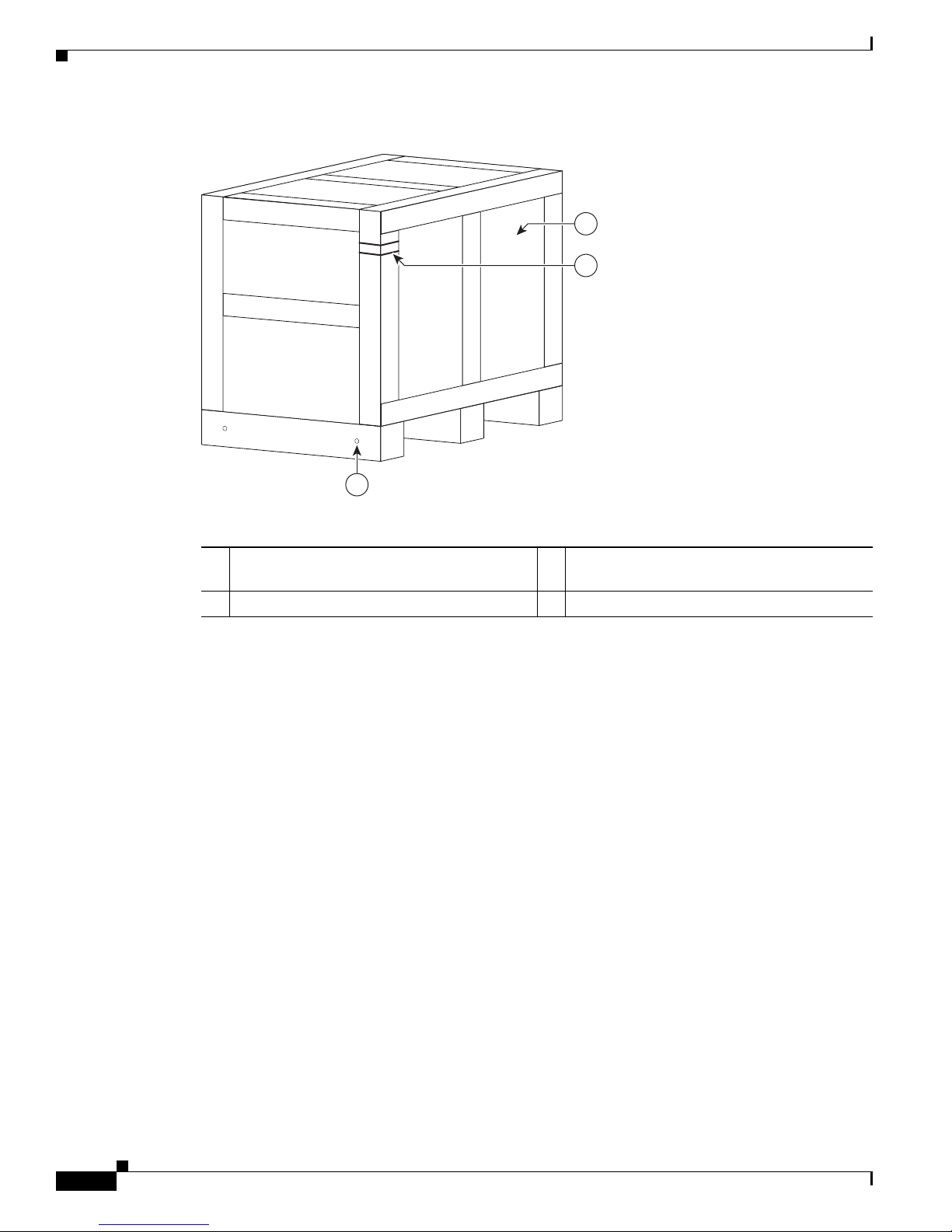
Step 1 Locate a large area to accommodate and remove the chassis crate.
Step 2 Remove the hinge mechanisms from the front door. Raise and twist the lock hinges at the base of the
plywood box (Figure 2-1).
Figure 2-1 Cisco NCS 6008 Chassis in Original Packaging
1 Lock latches 2 Large side panel 3 Three-sided plywood box
Cisco Network Convergence System 6000 Series Routers Unpacking, Moving, and Securing Guide
2-2
OL-29233-01
Page 23

Chapter 2
334606
1
The drill hole template is attached to the inside of the door (Figure 2-2).
Figure 2-2 Drill Hole Template Attached to Inside of Crate Door
Step 3
1 Drill hole template
Remove the large side panel of the wooden enclosure and set it aside carefully.
Note When setting aside the box, be careful to rest the wood on the floor so that the metal lock latches
are not bent or otherwise damaged. On most of the wooden enclosure, there should be rubber
bands above the bottom lock latches to hold them up so that they do not get damaged when
setting the enclosure down.
Step 4 Disengage the remaining latches from the shipping box. There are two on each side of the shipping box.
Cisco Network Convergence System 6000 Series Routers Unpacking, Moving, and Securing Guide
OL-29233-01
2-3
Page 24

Chapter 2
2
2
2
2
5
209192
1
3
4
Step 5 Using at least two people, one on each side of the box, lift and remove the three-sided box and place it
aside. The chassis is exposed on the pallet protected by a shipping bag secured with tape around the bag.
Step 6 Figure 2-3 shows the wooden box removed from the chassis and the protective bag still attached to the
chassis with tape.
Figure 2-3 Chassis Shipping Box Removed and Chassis Shipping Bag
1 Chassis pallet 4 Protective bag over chassis
2 Four bolts being removed from top shipping
5 Tape around chassis perimeter
cover
3 Top chassis shipping cover
Step 7 You need a ladder or step platform to remove the four top cover bolts (Figure 2-4). Use the 3/8-inch
ratchet wrench with an 11/16-inch socket to loosen the four bolts holding the top wood and frame
cushion system from the top of the shipping box. Once the four bolts are loosened, remove each bolt
manually and place aside, then remove the top wood and frame cushion system from the chassis.
Cisco Network Convergence System 6000 Series Routers Unpacking, Moving, and Securing Guide
2-4
OL-29233-01
Page 25

Chapter 2
Attaching the Dolly to the Chassis and Removing the Chassis Pallet
Figure 2-4 Remove Four Top Cover Bolts From Chassis Shipping Box
281962
Note Do not remove the chassis bag until you are ready to move and install the chassis.
Step 8 When you are ready to remove the chassis bag, unseal the tape that exists around the perimeter of the
chassis base and pull the bag off the chassis.
Attaching the Dolly to the Chassis and Removing the Chassis
Pallet
This section describes how to attach the dolly to the Cisco NCS 6008 chassis to remove the chassis
shipping pallet and prepare to move the chassis into place. Only the 90-degree dolly configuration is used
to remove the chassis from the pallet.
Figure 2-5 shows the dolly instruction label on the inside component of the dolly. Refer to this figure
when performing the steps to attach the dolly to the chassis in this section.
Cisco Network Convergence System 6000 Series Routers Unpacking, Moving, and Securing Guide
OL-29233-01
2-5
Page 26

Attaching the Dolly to the Chassis and Removing the Chassis Pallet
304065
Figure 2-5 Attaching the Dolly to the Chassis—Instructions
Chapter 2
Prerequisites
Before performing this task, unpack both the chassis and the dolly.
Required Tools and Equipment
• 3/8-inch ratchet wrench
• 17-mm socket
• 3/4-inch socket
• 12-mm hex bit
• Dolly (Cisco product ID NC-8-LIFT/B=)
Cisco Network Convergence System 6000 Series Routers Unpacking, Moving, and Securing Guide
2-6
OL-29233-01
Page 27

Chapter 2
Steps
Attaching the Dolly to the Chassis and Removing the Chassis Pallet
Step 1 Using the 3/8-inch ratchet wrench with 3/4-inch socket, remove the four bolts that connect the pallet to
each corner of the chassis base (Figure 2-6).
Figure 2-6 Remove Four Bolts That Attach Pallet to Chassis
281954
Cisco Network Convergence System 6000 Series Routers Unpacking, Moving, and Securing Guide
OL-29233-01
2-7
Page 28

Attaching the Dolly to the Chassis and Removing the Chassis Pallet
Step 2 Use the 3/8-inch ratchet wrench and socket to remove the two dolly-to-chassis lift brackets (Figure 2-7).
Repeat this step for the second dolly unit.
Figure 2-7 Remove Lift Brackets from Dolly
Chapter 2
1
2
2
3
209077
1 Lift bracket 3 Two lift bracket side pins on the removed lift bracket
2 M14 x 30 mm socket-head cap
screws
Note The lift brackets must be attached to the chassis first.
Step 3 Select a lift bracket. There are two identical lift brackets for the right front and left rear and two identical
lift brackets for the right rear and left front (Figure 2-8).
Cisco Network Convergence System 6000 Series Routers Unpacking, Moving, and Securing Guide
2-8
OL-29233-01
Page 29

Chapter 2
Attaching the Dolly to the Chassis and Removing the Chassis Pallet
Note The brackets are labeled as left or right (viewed from the front and rear).
Figure 2-8 Lift Brackets and Bolts
6
221
8
2
7
5
4
1 From left to right—left front and right
front lift brackets
2 Side pins on each lift bracket (inserted into
the chassis)
3 From left to right—Right rear and left rear
lift brackets
4 Eight M14 x 30 mm socket-head cap
screws (used to bolt the front and rear lift
brackets to the dolly)
5 Four M10 x 25 mm socket-head cap screws
(used to bolt the front and rear lift brackets
to the chassis)
3
3
10
6
1
9
6
2
6 Hole for M10 x 25 mm socket-head cap screw
7 Left front
8 Right rear
9 Right front
10 Left rear
303655
Step 4
Attach lift brackets to the chassis using the M10 x 25 mm screws (Figure 2-8). Align and insert the side
pins of the lift bracket to the lower left side of the front side of the chassis. Repeat this step with the right
lift bracket on the lower right side of the front side of the chassis. Figure 2-9 shows the oblique view of
attaching the lift brackets to the chassis.
Cisco Network Convergence System 6000 Series Routers Unpacking, Moving, and Securing Guide
OL-29233-01
2-9
Page 30

Attaching the Dolly to the Chassis and Removing the Chassis Pallet
304067
Figure 2-9 Attaching the Lift Brackets to the Chassis (Oblique View)
Chapter 2
Figure 2-10 shows the top-down view of attaching the lift brackets to the chassis.
Figure 2-10 Attaching the Lift Brackets to the Chassis (Top-Down View)
Step 5
Step 6 Attach the dolly to the chassis lift brackets using the M14 x 30 mm screws (Figure 2-8).
Step 7 If the dolly caster brakes are locked, then release them and slide the dolly towards the lift brackets on
Repeat Step 4 for the rear side of the chassis.
the chassis (Figure 2-11) so that the pins on the upper side of the unit align with the holes on the lift
brackets. The dolly and lift brackets must align with each other to easily insert the bolts and secure the
dolly to the lift brackets. Using two people, crank the dolly up (Figure 2-12).
Note To make aligning easier, as you slide the dolly, tilt it as needed.
Cisco Network Convergence System 6000 Series Routers Unpacking, Moving, and Securing Guide
2-10
OL-29233-01
Page 31

Chapter 2
149342
Attaching the Dolly to the Chassis and Removing the Chassis Pallet
Figure 2-11 Sliding the Dolly to the Lift Brackets
Step 8 After all bolts are secured, remove the chassis pallet following these steps:
a. Using two people (one person working on each dolly unit), turn the two lifting cranks to lift the
chassis about 3/4 of an inch above the pallet (Figure 2-12).
Note One person on each side of the dolly should raise the chassis enough to cleanly remove the base
pallet.
Cisco Network Convergence System 6000 Series Routers Unpacking, Moving, and Securing Guide
OL-29233-01
2-11
Page 32

Attaching the Dolly to the Chassis and Removing the Chassis Pallet
281958
Figure 2-12 Adjusting the Height of the Dolly
Chapter 2
b.
Slide the pallet from under the chassis (Figure 2-13).
Cisco Network Convergence System 6000 Series Routers Unpacking, Moving, and Securing Guide
2-12
OL-29233-01
Page 33

Chapter 2
281959
DO NOT TRANSPORT
Attaching the Dolly to the Chassis and Removing the Chassis Pallet
Figure 2-13 Slide Pallet From Under Chassis
c.
Using two people (one person working on each dolly unit), lower the chassis (Figure 2-14) to within
1 inch of the floor. See the height label on the dolly lift wheel assembly.
Cisco Network Convergence System 6000 Series Routers Unpacking, Moving, and Securing Guide
OL-29233-01
2-13
Page 34

Attaching the Dolly to the Chassis and Removing the Chassis Pallet
Figure 2-14 Lowering the Chassis
Chapter 2
Warning
OK TO TRANSPORT
281960
d. Depending on the transport route and the moving space requirements at your site, the dolly can be
used to move the chassis in the 90-degree or 180-degree configuration. The 180-degree position is
the recommended configuration for moving the chassis.
To reduce the risk of dolly instability, chassis damage, or personal injury, do not raise the equipment
more than 1 inch (2.4 cm) above the floor during transportation.
Statement 358
Cisco Network Convergence System 6000 Series Routers Unpacking, Moving, and Securing Guide
2-14
OL-29233-01
Page 35

Moving the Chassis
This chapter describes the things to consider as you move the Cisco NCS 6008 chassis from the loading
dock to the mounting location at the site.
• Important Notice, page 3-1
• Guidelines, page 3-1
• Verifying the Move Path, page 3-3
• Moving the Unpacked Chassis, page 3-5
Important Notice
A fork lift or pallet jack can be used to transport a crated chassis only.
Throughout this document we refer to the dolly (supplied by Cisco) as the required means to transport
the uncrated chassis from the shipping dock to the chassis final location.
In the event that the dolly supplied by Cisco is not the appropriate method of transportation, consult with
Cisco support to determine a method of transportation appropriate for the site. Ensure that the alternate
moving device is capable of supporting the weight of the chassis, moving the chassis safely, and
preventing the chassis from tipping too far and falling during transport.
CHAP T E R
3
Guidelines
When you use the dolly to move the as-shipped Cisco NCS 6008 chassis, follow these guidelines:
• When using the dolly to move the as-shipped chassis between locations, ensure that the chassis is
free of RP cards, FCs, LCs, fan trays, and power components (to reduce weight). Cisco strongly
recommends that you do not move a chassis while it’s fully populated.
Caution The crated Cisco NCS 6008 chassis is tall and heavy. Handle it carefully to reduce the risk of
tipping the chassis over too far so that it falls to the floor and causes injury. Cisco recommends
that at least two people move the chassis together to better support its size and weight.
• When raising or lowering the chassis, follow these guidelines:
–
Make sure that you have at least one person on each side of the chassis to turn the lifting cranks
on the dolly as simultaneously as possible.
Cisco Network Convergence System 6000 Series Routers Unpacking, Moving, and Securing Guide
OL-29233-01
3-1
Page 36

Guidelines
Chapter 3
–
Raise or lower the chassis only on a level surface.
–
Make sure that the caster brakes and anti-rotation pins are in the locked position.
–
Keep the casters on the floor at all times when you are raising or lowering the chassis.
–
Attempt to keep the chassis itself as level as possible when raising or lowering it with the dolly.
–
Use the height label on the dolly to make sure that you have the correct amount of ground
clearance. The label shows the recommended transport chassis engagement height, the height
that is not to be exceeded, and to ensure correct alignment between both dolly wheel assemblies.
• When moving the chassis in a hallway (standard hallway is 5 feet wide) or through aisles using a
dolly, follow these guidelines:
–
Make sure that you have at least two people to transport the chassis. Never transport the chassis
by yourself.
–
Use the dolly in the 180-degree configuration whenever possible when you move the chassis.
This configuration requires you to have passageways at least 50 inches in width to accommodate
the combined dolly and chassis width.
–
Use the dolly in the 90-degree configuration if your site restrictions require it. If hallway
constraints require you to use the 90-degree dolly configuration (24 inches), the chassis is more
likely to tip, so use extra care when transporting the chassis in that configuration.
–
When the dolly is used to transport the chassis, to reduce the risk of dolly instability, chassis
damage, or personal injury, do not raise the equipment more than 1 inch (2.4 cm) above the floor
during transportation.
–
The dolly can be used to transport the chassis over thresholds up to 1.5 inches.
Warning
Warning
• When transporting the chassis on a ramp, follow these guidelines:
–
Make sure that you have at least three people to transport the chassis up and down a ramp. One
person in the rear pushing, one person at the front pulling, and one steering the chassis.
–
The dolly is optimized to move the chassis on flat surfaces. It is not designed to move the chassis
on ramps greater than 1 inch of rise for every 6 inches of run. If the ramp exceeds this maximum
limit, consult with Cisco support.
–
Exercise extreme caution when moving chassis up an incline of any angle.
Caution Use the recommended 180-degree configuration to transport a chassis. If the 90-degree
configuration is used, then the chassis is more likely to tip. Use caution and take extra care in
rolling the chassis up a ramp. Always follow proper safety practices whenever moving a Cisco
NCS 6008 chassis.
This dolly is designed only for the temporary transportation of the Cisco equipment listed here. Do not
use it with any other device or for any other purpose. Cisco equipment designed for use with the dolly:
Cisco NCS 6008 Chassis.
Do not permanently locate the equipment on the dolly. Safely store the dolly after use.
Statement 356
Statement 357
Cisco Network Convergence System 6000 Series Routers Unpacking, Moving, and Securing Guide
3-2
OL-29233-01
Page 37

Chapter 3
Verifying the Move Path
Warning
Warning
Warning
Warning
Caution Dolly wheel casters and anti-rotation pins should be in the locked position when the dolly is not in use.
To reduce the risk of dolly instability, chassis damage, or personal injury, do not raise the equipment
more than 1 inch (2.4 cm) above the floor during transportation.
This dolly is designed to transport the equipment over short distances only.
In order to reduce the risk of chassis damage or personal injury when replacing a fully-loaded,
existing chassis, do not move the chassis in a configuration that is greater than the as-shipped
chassis. Before attaching the dolly and moving the chassis, remove the power system, fan trays, RP
cards, FCs, and LCs from the chassis.
To reduce the risk of dolly instability, chassis damage, or personal injury, do not transport the
equipment with the dolly raised higher than the maximum transport height shown on the dolly label,
and do not raise the equipment higher than required to remove the shipping pallet. For information
about maximum dolly heights, see the dolly instructions in this document.
Statement 367
Statement 358
Statement 359
Statement 368
Verifying the Move Path
Before moving the chassis, it is critical that you verify that the path that you are planning to use to move
the chassis to its final location can accommodate the chassis size and weight and the restrictions of the
chassis when using the dolly.
See Table 3-1 for a list of the restrictions for your move path, and verify that you have sufficient room
for the entire move path prior to moving the chassis.
Table 3-1 Cisco NCS 6008 Chassis Move-Path Specifications
Specification Value
Height (on dolly, with recommended 1 inch raise) 82 in. (208.3 cm)
Depth (on dolly, 90-degree dolly position) 70 in. (178 cm)
Depth (on dolly, 180-degree dolly position) 48 in. (122 cm)
Width (on dolly, 90-degree dolly position) 23.6 in. (60 cm)
Width (on dolly, 180-degree dolly position) 44 in. (112 cm)
Weight of chassis (as shipped, packaging removed) 775 lb (352 kg)
Weight of dolly 126 lb (57.3 kg)
Maximum recommended height from floor
(for chassis on dolly)
1.5 in. (3.8 cm)
Cisco Network Convergence System 6000 Series Routers Unpacking, Moving, and Securing Guide
OL-29233-01
3-3
Page 38

Verifying the Move Path
Note Allow a minimum gap of between 4 to 6 inches (10 to 15 cm) on each side of the combined chassis and
Chapter 3
dolly when moving it.
Figure 3-1 shows the recommended minimum space to turn the chassis on the dolly in its 90-degree and
180-degree configuration.
Figure 3-1 Recommended Turning Diameter of Dolly
180-degree configuration 90-degree configuration
Dolly
Dolly 180-degree
90-degree
3
Cisco NCS 6008
Chassis
Dolly 180-degree
2
1
1 Width (on dolly, 180-degree position) 44 in.
(112 cm)
2 Depth (on dolly, 180-degree position) 48 in.
(122 cm)
3 Turn radius (on dolly, 180-degree position)
33 in. (83 cm)
6
Cisco NCS 6008
Chassis
Dolly
90-degree
5
4
303608
4 Width (on dolly, 90-degree position) 24 in.
(60 cm)
5 Depth (on dolly, 90-degree position) 70 in.
(178 cm)
6 Turn radius (on dolly, 90-degree position)
37 in. (94 cm)
Table 3-2 provides the dolly width and the recommended aisle width turning radius for the 90-degree
and 180-degree dolly configuration.
Table 3-2 Chassis Turning Recommendations
Dolly Configuration Width of Dolly Recommended Aisle Width
90-degree dolly position 24 in. (60 cm) 32 in. (81 cm)*
180-degree dolly position 44 in. (112 cm) 52 in. (132 cm)
*Aisle width may be different when transporting the chassis around a corner.
Cisco Network Convergence System 6000 Series Routers Unpacking, Moving, and Securing Guide
3-4
OL-29233-01
Page 39

Chapter 3
303607
Existing Cisco
NCS 6008 Chassis
Existing Cisco
NCS 6008 Chassis
3
1
4
5
2
Moving the Unpacked Chassis
Figure 3-2 is a top view of the minimum aisle space required to install the Cisco NCS 6008 chassis
without using the dolly supplied by Cisco. This space is exclusive of both the PDU brackets (mounted
on both sides), and the router cosmetics.
Figure 3-2 Minimum Aisle Space Requirements to Install the Cisco NCS 6008 Chassis—Top View
(With Dolly Removed)
1 Chassis front 4 Chassis rear
2 Chassis side 5 Chassis side
3 Moving space requirement: 34.7 in. (95 cm)
Moving the Unpacked Chassis
Prerequisites
Before performing this task, make sure that the dolly is in the correct configuration, is firmly attached
to the unpacked chassis, and the dolly brakes are in the locked position.
Note If a dolly configuration change is required, see the “Modifying the Dolly Configuration” section on
page 1-11.
Cisco Network Convergence System 6000 Series Routers Unpacking, Moving, and Securing Guide
OL-29233-01
3-5
Page 40

Moving the Unpacked Chassis
Steps
Step 1 With a person on each side of the chassis, turn all four lifting cranks of the dolly slowly clockwise. Lift
Chapter 3
the dolly to the “Transport” marking on the height label on each lift assembly leg. The dolly can be used
to transport the chassis at heights from 0.5 to 3.0 inches; the transport height is 1 inch max and 1.5 inch
max for going over thresholds.
Note The dolly has four separate lifting cranks, each of which works independently. It is best to turn
each lifting crank simultaneously when lifting the chassis to keep the chassis as level as possible
so as to not put undue stress on the chassis frame or dolly and to reduce the risk of tipping too far.
Note The 180-degree position is the recommended configuration for moving the chassis. If needed
because of site requirements, rotate the dolly to the 90-degree position. If you are transporting
in a 90-degree configuration, then have at least two people moving the chassis to prevent any
transporting hazard. See the “Modifying the Dolly Configuration” section on page 1-11 for
further information.
Note You must lower the chassis completely to the floor before rotating the outrigger legs. When you
have rotated the lifting cranks, raise the chassis again. See the “Modifying the Dolly
Configuration” section on page 1-11 for further information.
Step 2 Unlock the dolly caster anti-rotation and brake systems.
Note The dolly is optimized to move the chassis on flat surfaces. It is not designed to move the chassis
up stairs, over curbs, up ramps, or over bumps more than 1.5 inches high (such as door
thresholds).
Step 3 Use at least three people to transport the chassis up any ramp. Position one person in the front of the
chassis to pull, one person at the rear of chassis to push, and one person steering the chassis.
Step 4 Carefully roll the chassis into position near its mounting location.
Cisco Network Convergence System 6000 Series Routers Unpacking, Moving, and Securing Guide
3-6
OL-29233-01
Page 41

Prerequisites
CHAP T E R
4
Securing the Chassis
This chapter describes how to secure the Cisco NCS 6008 chassis to a concrete floor. The chassis is
shipped with a drill hole template to assist you in putting the bolts in the proper position on the floor.
The template is used for both raised floors and slabs. The drill hole template identifies primary and
secondary locations for securing the chassis to the floor. Whenever possible, use the following:
• Primary mounting locations
• Secondary locations only when the primary locations are not available
The instructions in this chapter are specific to securing the chassis to a concrete floor. The instructions
for securing the chassis to a raised floor vary from site to site, depending on such details as whether your
floor needs additional support (as local practice applies for raised floors), and where (depending on the
location of the floor tiles) the bolt holes need to be. Work with your facilities representative to determine
your needs for your particular site.
Identify chassis location and ensure that there is sufficient space before performing this task.
Required Tools and Equipment
• Drill hole template
• Marking pen or pencil
• 3/8-inch ratchet wrench
• Set of standard and metric sockets
• Drill and bits for masonry and wood
• #1 Phillips screwdriver
Note The full list of tools depends on the anchor bolt kit that you use. See the documentation for your anchor
bolt kit for details.
Cisco Network Convergence System 6000 Series Routers Unpacking, Moving, and Securing Guide
OL-29233-01
4-1
Page 42

Steps
304215
Chapter 4
Step 1 Using the drill hole template, mark the pilot holes on the floor at the identified locations.
Step 2 Remove the drill hole template, and drill the indicated anchor bolt holes into the floor at the pilot hole
locations.
Step 3 If an alternate floor mounting pattern is required, remove the lower side panels (left and right sides of
the chassis) to expose additional floor mounting holes (Figure 4-1).
Figure 4-1 Remove Lower Side Panels to Expose Additional Floor Mounting Holes
Cisco Network Convergence System 6000 Series Routers Unpacking, Moving, and Securing Guide
4-2
OL-29233-01
Page 43

Chapter 4
Unpacking Chassis Components
Step 4 Carefully move the chassis into place over the bolt holes. See the “Moving the Unpacked Chassis”
section on page 3-5 for details on moving the chassis with the dolly.
Note Where side clearance is not enough to use the dolly, you must first lower the chassis to the floor
and then slide it into place.
Step 5 Lock the dolly caster anti-rotation and brake systems.
Step 6 With a person on each side of the chassis, turn all four lifting cranks of the dolly counterclockwise slowly
to lower the chassis to the floor.
Note The dolly has four separate lifting cranks, each of which works independently when lifting or
lowering the chassis. It is best to turn the lifting cranks simultaneously when lifting the chassis
so as to not put undue stress on the chassis frame or dolly and reduce the risk of tipping too far.
Step 7 Remove the dolly from the chassis.
Warning
Step 8 Insert all anchor bolts.
Step 9 Tighten all bolts and nuts.
Do not permanently locate the equipment on the dolly. Safely store the dolly after use.
Statement 357
Unpacking Chassis Components
The remaining shipping boxes and pallets are now ready to be delivered from the receiving/shipping
dock or a site holding area to the final location of the chassis.
Steps
Step 1 If possible, move the pallets to the same location as the unpacked and secured chassis. If not possible,
move the individual boxes containing the various components to the chassis location.
Note All components are packaged separately. Cards are attached and installed on a wooden board
insert held in place by captive Phillips screws.
Step 2 Unpack all primary pallet parts from the packaging, and set the parts aside for installation.
Step 3 Unpack all secondary pallet parts from the packaging, and set the parts aside for installation.
Note Do not unpack individual cards until you are ready to install the cards in the chassis.
Cisco Network Convergence System 6000 Series Routers Unpacking, Moving, and Securing Guide
OL-29233-01
4-3
Page 44

Component Return Information
Step 4 Unpack all power components from the packaging, and set the parts carefully aside on an ESD-immune
surface for installation.
Step 5 Unpack all exterior cosmetic parts from the packaging and set the parts aside.
Step 6 Go to the Cisco Network Convergence System 6000 Series Routers Hardware Installation Guide for
installation instructions of individual components.
Component Return Information
Before preparing to return the product or product components, you must contact Cisco technical support
and provide them with the details of your difficulty. Cisco technical support must confirm your product
or component failure before assigning an RMA number for return shipment. For additional information,
see the “Obtaining Additional Information and Support” section on page -viii.
To facilitate your conversation with Cisco technical support, locate and note the serial number for the
chassis. The serial number label for the Cisco NCS 6008 chassis is located on the rear side of the chassis,
lower left corner.
Chapter 4
Cisco Network Convergence System 6000 Series Routers Unpacking, Moving, and Securing Guide
4-4
OL-29233-01
 Loading...