

Page 1

Cisco Network Convergence System 6000 Fabric Card Chassis Hardware Installation Guide
First Published: 2014-07-24
Last Modified: 2018-03-30
Americas Headquarters
Cisco Systems, Inc.
170 West Tasman Drive
San Jose, CA 95134-1706
USA
http://www.cisco.com
Tel: 408 526-4000
800 553-NETS (6387)
Fax: 408 527-0883
Page 2

THE SPECIFICATIONS AND INFORMATION REGARDING THE PRODUCTS IN THIS MANUAL ARE SUBJECT TO CHANGE WITHOUT NOTICE. ALL STATEMENTS,
INFORMATION, AND RECOMMENDATIONS IN THIS MANUAL ARE BELIEVED TO BE ACCURATE BUT ARE PRESENTED WITHOUT WARRANTY OF ANY KIND,
EXPRESS OR IMPLIED. USERS MUST TAKE FULL RESPONSIBILITY FOR THEIR APPLICATION OF ANY PRODUCTS.
THE SOFTWARE LICENSE AND LIMITED WARRANTY FOR THE ACCOMPANYING PRODUCT ARE SET FORTH IN THE INFORMATION PACKET THAT SHIPPED WITH
THE PRODUCT AND ARE INCORPORATED HEREIN BY THIS REFERENCE. IF YOU ARE UNABLE TO LOCATE THE SOFTWARE LICENSE OR LIMITED WARRANTY,
CONTACT YOUR CISCO REPRESENTATIVE FOR A COPY.
The Cisco implementation of TCP header compression is an adaptation of a program developed by the University of California, Berkeley (UCB) as part of UCB's public domain version
of the UNIX operating system. All rights reserved. Copyright©1981, Regents of the University of California.
NOTWITHSTANDING ANY OTHER WARRANTY HEREIN, ALL DOCUMENT FILES AND SOFTWARE OF THESE SUPPLIERS ARE PROVIDED “AS IS" WITH ALL FAULTS.
CISCO AND THE ABOVE-NAMED SUPPLIERS DISCLAIM ALL WARRANTIES, EXPRESSED OR IMPLIED, INCLUDING, WITHOUT LIMITATION, THOSE OF
MERCHANTABILITY, FITNESS FOR A PARTICULAR PURPOSE AND NONINFRINGEMENT OR ARISING FROM A COURSE OF DEALING, USAGE, OR TRADE PRACTICE.
IN NO EVENT SHALL CISCO OR ITS SUPPLIERS BE LIABLE FOR ANY INDIRECT, SPECIAL, CONSEQUENTIAL, OR INCIDENTAL DAMAGES, INCLUDING, WITHOUT
LIMITATION, LOST PROFITS OR LOSS OR DAMAGE TO DATA ARISING OUT OF THE USE OR INABILITY TO USE THIS MANUAL, EVEN IF CISCO OR ITS SUPPLIERS
HAVE BEEN ADVISED OF THE POSSIBILITY OF SUCH DAMAGES.
Any Internet Protocol (IP) addresses and phone numbers used in this document are not intended to be actual addresses and phone numbers. Any examples, command display output, network
topology diagrams, and other figures included in the document are shown for illustrative purposes only. Any use of actual IP addresses or phone numbers in illustrative content is unintentional
and coincidental.
Cisco and the Cisco logo are trademarks or registered trademarks of Cisco and/or its affiliates in the U.S. and other countries. To view a list of Cisco trademarks, go to this URL: https:/
/www.cisco.com/go/trademarks. Third-party trademarks mentioned are the property of their respective owners. The use of the word partner does not imply a partnership
relationship between Cisco and any other company. (1721R)
©
2016-2018 Cisco Systems, Inc. All rights reserved.
Page 3

CONTENTS
Preface
CHAPTER 1
CHAPTER 2
Preface xi
Audience xi
Documentation Conventions xi
Related Documentation xiii
Changes to This Document xiii
Obtaining Documentation and Submitting a Service Request xiii
Installation Roadmap 1
Installation Roadmap 1
Overview 3
About the Cisco NCS 6000 Fabric Card Chassis 3
Fabric Card Chassis Components 4
Slot Numbers 8
Cable Management 10
Safety Guidelines 10
CHAPTER 3
Installing the Power Enclosure, Power Trays, and Exterior Cosmetics 13
About the Power Enclosure 13
Installing the Power Enclosure 14
Required Tools and Equipment 14
Steps 15
Installing the Power Trays 16
About the AC and DC Power Trays 16
Installing an AC or DC Power Tray 18
Prerequisites 18
Required Tools and Equipment 19
Cisco Network Convergence System 6000 Fabric Card Chassis Hardware Installation Guide
iii
Page 4

Contents
Steps 19
Installing the Exterior Cosmetics 20
Overview of the Exterior Cosmetics 21
Installing the Front Exterior Cosmetics 22
Prerequisites 23
Required Tools and Equipment 23
Steps 23
Installing the Rear Exterior Cosmetics 28
Prerequisites 28
Required Tools and Equipment 28
Steps 28
CHAPTER 4
Installing the Power Components 35
Power System Overview 35
Prerequisites 35
Installing the Fabric Card Chassis Ground Cable 35
Required Tools and Equipment 36
Steps 38
AC Power System 39
Overview of the AC Power System 39
Installing an AC Power Distribution Unit 39
Mounting the PDU 40
Installing the Tie-Down Bar 42
DC Power System 43
Installing the Power Modules and Input Power Cables 45
Installing an AC or DC Power Module 46
Prerequisites 48
Required Tools and Equipment 48
Steps 49
About the Power Module Status Indicators 50
Installing an AC or DC Power Module Slot Cover 52
Prerequisites 52
Required Tools and Equipment 52
Steps 53
Installing AC Input Power Cords 53
Cisco Network Convergence System 6000 Fabric Card Chassis Hardware Installation Guide
iv
Page 5

Contents
Prerequisites 53
Required Tools and Equipment 54
Steps 54
Installing DC Input Power Cables 55
Prerequisites 55
Required Tools and Equipment 55
Steps 56
Powering On and Powering Off the Fabric Card Chassis 57
Powering On the Fabric Card Chassis 57
Prerequisites 57
Required Tools and Equipment 58
Steps 58
CHAPTER 5
Powering Off the Fabric Card Chassis 59
Steps 59
Installing the Shelf Controller Cards and Fabric Cards 61
About Installing Cards and Associated Components 62
Preventing Electrostatic Discharge 62
Guidelines for Installing a Card 62
Steps for OIR Fabric Card Removal 63
About Cable Management Brackets 64
Installing and Removing an Impedance Carrier 66
Installing an S2 Fabric Card Impedance Carrier 67
Prerequisites 67
Required Tools and Equipment 67
Steps 68
Removing an S2 Fabric Card Impedance Carrier 68
Prerequisites 68
Required Tools and Equipment 68
Steps 68
About the SC and SC-SW Cards 69
Front Panel Ports 70
Installing an SC or SC-SW Card 71
Prerequisites 72
Required Tools and Equipment 72
Cisco Network Convergence System 6000 Fabric Card Chassis Hardware Installation Guide
v
Page 6

Contents
Steps 72
Verifying the Installation of an SC or SC-SW Card 74
Troubleshooting the SC or SC-SW Card 77
About the Fabric Cards 77
S2 Fabric Card 78
S13 and Universal Fabric Card 78
Installing the Fabric Cards 79
Installing an S2 Fabric Card 79
Prerequisites 79
Required Tools and Equipment 79
Steps 80
Verifying the Installation of an S2 Fabric Card 82
S2 Fabric Card LEDs 83
CHAPTER 6
Installing an S13 MC Fabric Card or Universal Fabric Card 85
Removing and Replacing Chassis Components 87
Removing the Exterior Cosmetics 87
Prerequisites 87
Required Tools and Equipment 87
Removing the Front Exterior Cosmetics 88
Removing the Rear Exterior Cosmetics 94
Removing the Power Components 96
Removing AC Input Power Cords 96
Prerequisites 96
Required Tools and Equipment 96
Steps 97
Removing DC Input Power Cables 97
Prerequisites 97
Steps 98
Replacing an AC or DC Power Tray 99
Prerequisites 99
Required Tools and Equipment 99
Steps 100
Removing a Power Module Slot Cover 101
Prerequisites 101
Cisco Network Convergence System 6000 Fabric Card Chassis Hardware Installation Guide
vi
Page 7

Contents
Steps 101
Removing an AC or DC Power Module 102
Prerequisites 102
Required Tools and Equipment 102
Steps 103
Removing the FCC Ground Cable 103
Prerequisites 104
Required Tools and Equipment 104
Steps 105
Replacing a Power Control Module 105
Required Tools and Equipment 106
Steps 106
Removing the Power Enclosure 108
Required Tools and Equipment 108
Steps 109
Replacing the Fan Trays and Air Filter 110
About the Fan Trays and Air Filter 110
About the Fan Trays 111
Fan Tray LEDs 111
About the Air Filter 112
Replacing the Fan Tray 112
Prerequisites 112
Required Tools and Equipment 112
Steps 113
Replacing the Air Filter 114
Steps 114
Removing the Shelf Controller Cards and Fabric Cards 115
Guidelines for Removing a Card 116
Removing an SC or SC-SW Card 116
Prerequisites 116
Required Tools and Equipment 117
Steps 118
Removing an S2 Fabric Card 120
Guidelines for Handling CXP2 Optical Modules 120
Prerequisites 122
Cisco Network Convergence System 6000 Fabric Card Chassis Hardware Installation Guide
vii
Page 8

Contents
Required Tools and Equipment 122
Steps 123
Removing an S13 Multi-Chassis Fabric Card 125
APPENDIX A
APPENDIX B
APPENDIX C
System Specifications 127
Fabric Card Chassis Specifications 127
Power Specifications 128
Environmental Specifications 129
Regulatory, Compliance, and Safety Specifications 130
System Product IDs 131
Component Product IDs 131
Fabric Card Product IDs 133
Cosmetic Product IDs 134
Accessory Product IDs 134
Optical Module IDs 135
Cabling a Multi-Chassis Configuration 137
About the Cisco NCS 6000 Multi-Chassis System 137
Prerequisites 138
Cabling Requirements 138
MPO-24 Cable Specifications 140
Required Tools and Equipment 142
Cabling Overview 143
Cable Routing Considerations 143
General Cabling Procedures 144
Safety Guidelines 144
Cabling the Ethernet Control Plane Network 145
Cabling the Control Plane for a 2+1 Multi-Chassis system 145
Cabling the Control Plane for a 2+2 Multi-Chassis System 147
Cabling the Fabric 149
Fabric Overview 150
Multi-Chassis 2+1 Configuration 155
Prerequisites 155
Configuring a 2+1 Configuration with Six S2 FCs 155
viii
Cisco Network Convergence System 6000 Fabric Card Chassis Hardware Installation Guide
Page 9

Contents
2+1 Software Configuration (Six S2 Fabric Cards) 158
Configuring a 2+1 Configuration with 12 S2 FCs 159
2+1 Software Configuration (12 S2 Fabric Cards) 162
Multi-Chassis 2+2 Configuration 163
Prerequisites 163
Configuring a 2+2 Configuration with 12 S2 Fabric Cards 163
2+2 Software Configuration (12 S2 Fabric Cards) 167
Configuring a 2+2 Configuration with 24 S2 Fabric Cards 168
2+2 Software Configuration (24 S2 Fabric Cards) 172
Multi-Chassis 4+2 Configuration 173
Prerequisites 173
Configuring a 4+2 Configuration with 12 S2 Fabric Cards 174
4+2 Software Configuration (12 S2 Fabric Cards) 181
Configuring a 4+2 Configuration with 24 S2 Fabric Cards 181
4+2 Software Configuration (24 S2 Fabric Cards) 188
Cisco Network Convergence System 6000 Fabric Card Chassis Hardware Installation Guide
ix
Page 10

Contents
Cisco Network Convergence System 6000 Fabric Card Chassis Hardware Installation Guide
x
Page 11

Audience
Preface
This document describes how to install a Cisco Network Convergence System (NCS) 6000 Fabric Card
Chassis and its components. The Cisco NCS 6000 Fabric Card Chassis (FCC) is a product in the Cisco
Network Convergence System 6000 Series family. The chassis specifications are included in Appendix A
“System Specifications.” The Cisco product IDs (PIDs) are listed in Appendix B “System Product IDs.”
Audience, page xi
•
Documentation Conventions, page xi
•
Related Documentation, page xiii
•
Changes to This Document, page xiii
•
Obtaining Documentation and Submitting a Service Request, page xiii
•
This guide is intended for chassis installers and Cisco installation partners who are responsible for installing
the Cisco NCS 6000 FCC and its components. The installers are expected to have installed networking hardware
in the past. No additional knowledge of routing or the Cisco IOS XR software is assumed.
Documentation Conventions
This document uses the following conventions:
Italic font
{x | y | z}
Cisco Network Convergence System 6000 Fabric Card Chassis Hardware Installation Guide
DescriptionConvention
Commands and keywords and user-entered text appear in bold font.bold font
Document titles, new or emphasized terms, and arguments for which you
supply values are in italic font.
Elements in square brackets are optional.[ ]
Required alternative keywords are grouped in braces and separated by
vertical bars.
xi
Page 12
Documentation Conventions
Preface
DescriptionConvention
Note
[x | y | z]
Optional alternative keywords are grouped in brackets and separated by
vertical bars.
string
A nonquoted set of characters. Do not use quotation marks around the
string or the string will include the quotation marks.
courier font
Terminal sessions and information the system displays appear in courier
font.
Indicates a variable for which you supply values, in context where italics
cannot be used.
Nonprinting characters such as passwords are in angle brackets.< >
Default responses to system prompts are in square brackets.[ ]
!, #
An exclamation point (!) or a pound sign (#) at the beginning of a line
of code indicates a comment line.
Means reader take note. Notes contain helpful suggestions or references to material not covered in the
manual.
Tip
Caution
Warning
Warning
Means the following information will help you solve a problem. The tips information might not be
troubleshooting or even an action, but could be useful information, similar to a Timesaver.
Means reader be careful. In this situation, you might perform an action that could result in equipment
damage or loss of data.
IMPORTANT SAFETY INSTRUCTIONS
This warning symbol means danger. You are in a situation that could cause bodily injury. Before you
work on any equipment, be aware of the hazards involved with electrical circuitry and be familiar with
standard practices for preventing accidents. Use the statement number provided at the end of each warning
to locate its translation in the translated safety warnings that accompanied this device.
SAVE THESE INSTRUCTIONS
Statements using this symbol are provided for additional information and to comply with regulatory and
customer requirements.
xii
Cisco Network Convergence System 6000 Fabric Card Chassis Hardware Installation Guide
Page 13
Preface
Related Documentation
For complete planning, installation, and configuration information, see the following documents that are
available on Cisco.com at the following URL:
http://www.cisco.com/c/en/us/support/routers/network-convergence-system-6000-series-router/products-installation-guides-list.html.
Cisco Network Convergence System 6000 Series Routers Site Planning Guide
•
Cisco Network Convergence System 6000 Series Routers Unpacking, Moving, and Securing Guide
•
Cisco Network Convergence System 6000 Series Routers Hardware Installation Guide
•
Regulatory Compliance and Safety Information for the Cisco Network Convergence System 6000 Series
•
Routers
Changes to This Document
Related Documentation
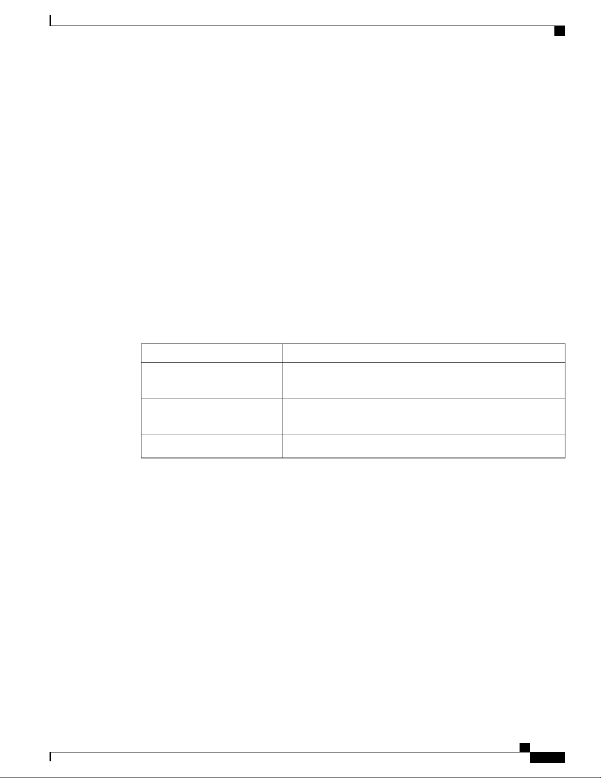
This table lists the technical changes made to this document since it was first created.
Table 1: Changes to This Document
SummaryDate
January 2018
September 2014
Added support for the 2nd generation S2 fabric card (NCS-F-FC2) and
CXP2 optics modules (ONS-CXP2-SR25).
Added Telercordia GR-63 requirements for air filter and other minor
updates.
This document introduces the Cisco NCS 6000 Fabric Card Chassis.July 2014
Obtaining Documentation and Submitting a Service Request
For information on obtaining documentation, using the Cisco Bug Search Tool (BST), submitting a service
request, and gathering additional information, see What's New in Cisco Product Documentation, at: http://
www.cisco.com/c/en/us/td/docs/general/whatsnew/whatsnew.html.
Subscribe to What's New in Cisco Product Documentation, which lists all new and revised Cisco technical
documentation as an RSS feed and delivers content directly to your desktop using a reader application. The
RSS feeds are a free service, and Cisco currently supports RSS Version 2.0.
Cisco Network Convergence System 6000 Fabric Card Chassis Hardware Installation Guide
xiii
Page 14

Obtaining Documentation and Submitting a Service Request
Preface
xiv
Cisco Network Convergence System 6000 Fabric Card Chassis Hardware Installation Guide
Page 15

Installation Roadmap
Installation Roadmap , page 1
•
Installation Roadmap
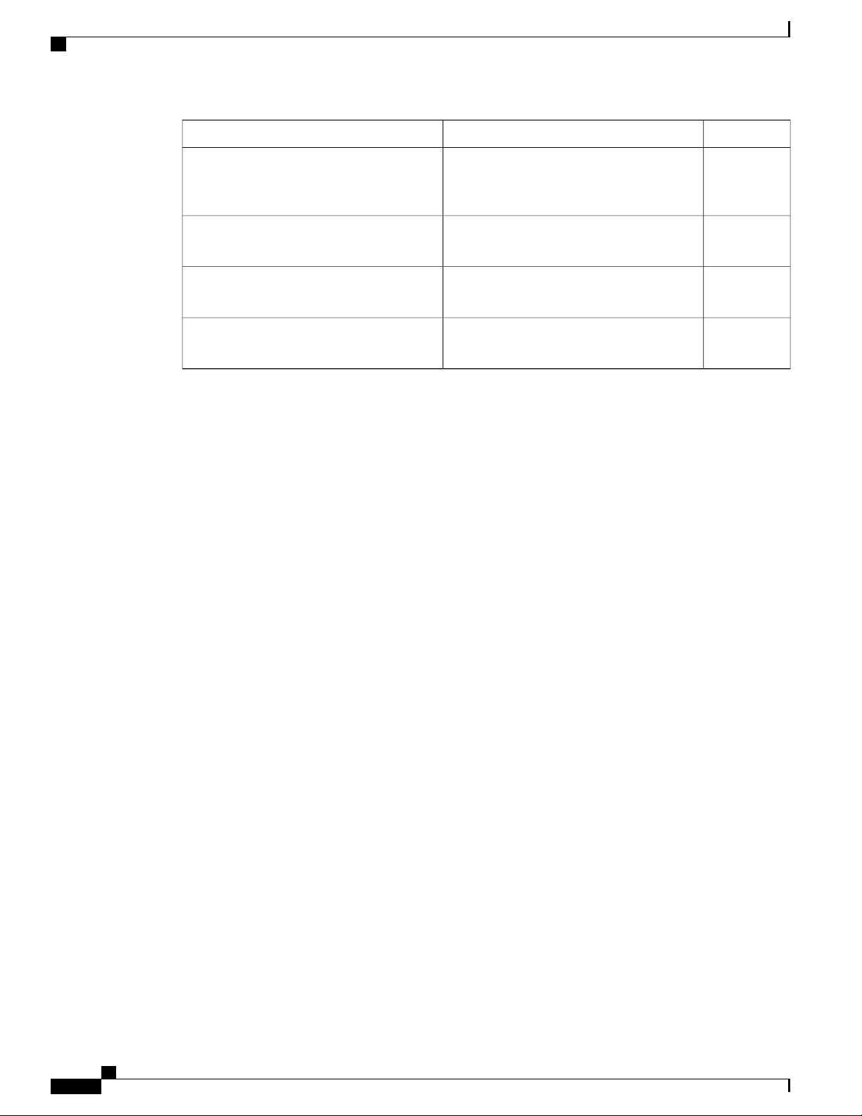
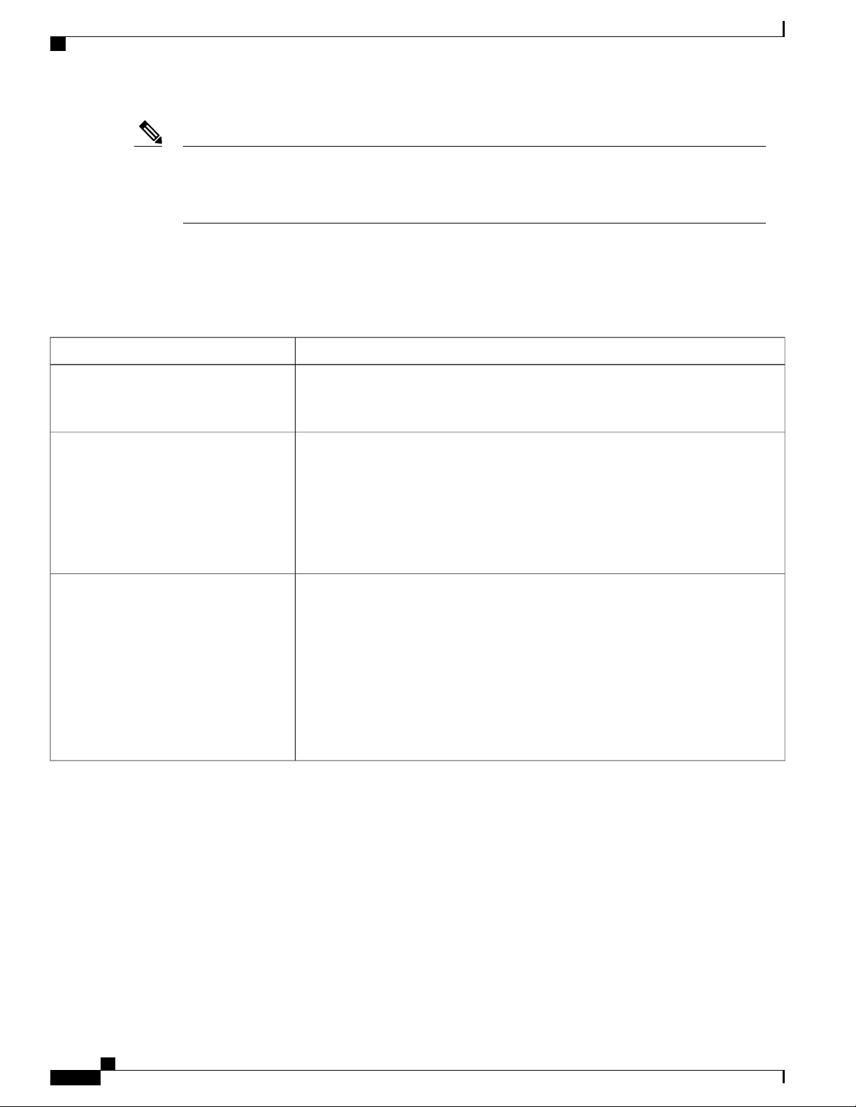
The following table lists the tasks to install the Cisco NCS 6000 Fabric Card Chassis (FCC) and its components
and prepare the system for operation. Use this table as a checklist to ensure that all components are properly
installed in the correct order. For information about a step, see the respective section of this installation guide.
Table 2: Overview of Installation Steps
CHAPTER 1
CheckSeeStep
1. Verify that the FCC is securely bolted to
the floor.
2. Install the power enclosure.
3. Ground the FCC.
4. Install the power trays.
5. Install the external cosmetics on the front
of the FCC.
6. Install the external cosmetics on the rear
of the FCC.
7. Install power modules in the power trays.
Cisco Network Convergence System 6000
Series Routers Unpacking, Moving, and
Securing Guide
About the Power Enclosure, on page 13
section
Installing the Fabric Card Chassis Ground
Cable, on page 35 section
Installing an AC or DC Power Tray, on page
18 section
Installing the Front Exterior Cosmetics, on
page 22 section
Installing the Rear Exterior Cosmetics, on
page 28
Installing an AC or DC Power Module , on
page 46 section
Cisco Network Convergence System 6000 Fabric Card Chassis Hardware Installation Guide
1
Page 16
Installation Roadmap
Installation Roadmap
CheckSeeStep
8. Install either AC or DC input power
connections to the power trays.
9. Power on the FCC.
10. Install the shelf controller cards and fabric
cards in the FCC.
11. Connect the cabling for multi-chassis
configuration.
Installing AC Input Power Cords, on page
53 or Installing DC Input Power Cables , on
page 55 section
Powering On the Fabric Card Chassis , on
page 57 section
Installing the Shelf Controller Cards and
Fabric Cards , on page 61 section
Cabling a Multi-Chassis Configuration, on
page 137 section
Cisco Network Convergence System 6000 Fabric Card Chassis Hardware Installation Guide
2
Page 17

CHAPTER 2
Overview
This chapter provides an overview of the Cisco NCS 6000 Fabric Card Chassis.
About the Cisco NCS 6000 Fabric Card Chassis, page 3
•
Fabric Card Chassis Components, page 4
•
Slot Numbers, page 8
•
Cable Management , page 10
•
Safety Guidelines, page 10
•
About the Cisco NCS 6000 Fabric Card Chassis
The Cisco NCS 6000 Fabric Card Chassis is a highly scalable core routing platform designed for service
providers to build next generation multi-service networks that provide video, data and voice services. The
fabric card chassis, also known as a switch fabric chassis, is referred to in this document as the Cisco NCS
6000 FCC.
The Cisco NCS 6000 FCC is part of the Cisco NCS 6000 Multi-Chassis system that also includes the Cisco
NCS 6008 8-slot line card chassis (LCC). The system can expand from a single chassis to various multi-chassis
configurations for increased routing capacity and is capable of supporting up to 16 LCCs interconnected to
4 FCCs.
The Cisco NCS 6000 Multi-Chassis system scales by interconnecting up to 16 LCCs through up to four FCCs.
These connections are made from the LCC switch fabric cards to the FCC fabric cards through CXP or CXP2
optical interconnects. The NCS 6000 has a 3-stage switch fabric architecture. In a multi-chassis configuration,
the first and third stages are implemented by the S13 fabric cards on the LCC, and the second stage is performed
by the S2 fabric cards on the FCC. For an overview of the fabric system and multi-chassis cabling
configurations, see About the Cisco NCS 6000 Multi-Chassis System, on page 137.
The Cisco NCS 6000 FCC has an integrated rack and is bolted to the facility floor (no external rack is required).
The FCC contains its own power and cooling systems. Power systems are available using either AC or DC
power.
This installation guide provides the installation procedures for the FCC. For installation information about
the LCC, see the Cisco Network Convergence System 6000 Series Routers Hardware Installation Guide.
Cisco Network Convergence System 6000 Fabric Card Chassis Hardware Installation Guide
3
Page 18
Fabric Card Chassis Components
Overview
Note
The installation of a Cisco NCS 6000 FCC may require space, floor loading, power, and cooling
modifications to a facility. Therefore, you should plan the site well in advance of the scheduled delivery
of the FCC. For site preparation information, see the Cisco Network Convergence System 6000 Series
Routers Site Planning Guide.
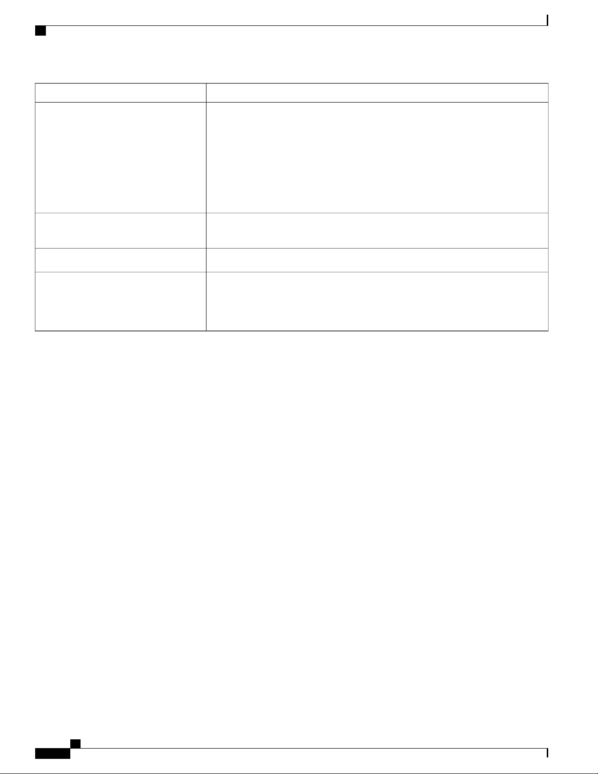
Fabric Card Chassis Components
Table 3: Main Components of the Cisco NCS 6000 FCC
DescriptionComponent
Chassis midplane
S2 Fabric Cards (FCs)
The chassis midplane distributes power and provides interconnections for other
components in the system. Each S2 FC is connected through the midplane to the FCC.
The midplane is not a field-replaceable unit (FRU).
The FCC has 12 FC slots: Six FC slots on the front side of the FCC (three slots on the
upper cage and three slots on the lower cage) and six FC slots on the rear side of the
FCC (three slots on the upper cage and three slots on the lower cage). See Figure 3:
Cisco NCS 6000 FCC Slot Numbers. For an overview of the fabric, see Fabric
Overview, on page 150.
Each S2 FC supports up to 32 CXP modules. Each S2 FC2 supports up to 32 CXP2
modules.
CXP/CXP2 optical modules and connectors
The connections between the LCC and the FCC are implemented through a number of
bi-directional optical links. Pluggable CXP/CXP2 optics are used for these interconnects.
In 1T multi-chassis (MC) mode, CXP optical modules connect the S2 FC and S13
•
FC together.
In 2T MC mode, CXP2 optical modules connect the S2 FC2 and UFC together.
•
The CXP module (CXP-100G-SR12) and the CXP2 module (ONS-CXP2-SR25) use
a 24-fiber MPO connector that supports 12 bi-directional optical links up to 100 meters
of OM-4 multi-mode fiber.
Cisco Network Convergence System 6000 Fabric Card Chassis Hardware Installation Guide
4
Page 19

Overview
Fabric Card Chassis Components
DescriptionComponent
Shelf Controller Cards
Power enclosure
The Cisco NCS 6000 FCC offers two types of shelf controller cards: the SC card and
the SC-SW card.
The SC-SW card is a 56-port combination card that integrates a shelf controller
•
and switch for the NCS 6000 Control Ethernet into one physical card. The shelf
controller (SC) portion controls the route processing and management functions
for the FCC and its components. The switch (SW) portion interconnects all the
route processors (RPs) and SCs in a multi-chassis system. The LEDs on the SC-SW
indicate active alarm conditions.
The SC card is a shelf-controller-only card.
•
For detailed information about the SC-SW and SC cards, see About the SC and SC-SW
Cards, on page 69.
The FCC ships with two shelf controller cards, either two SC-SW cards or a combination
of one SC-SW card and one SC card pre-installed in the FCC. The cards are inserted
into two dedicated slots on the front of the FCC. One SC-SW or SC card installs into
slot SC0 on the upper card cage and the other SC-SW or SC card installs into slot SC1
on the lower card cage (Figure 3: Cisco NCS 6000 FCC Slot Numbers). Both the upper
and lower card slots are identical. The secondary card is installed for redundancy, so
that the loss or removal of a single card does not bring down the FCC. At least one
SC-SW or SC card must be operational for the FCC to function.
Note
In a multi-chassis system with more than one FCC, we recommend that the
SC-SW cards are not installed in the same FCC.
The power enclosure is a separate unit that is installed at the top of the FCC (Figure 5:
FCC Power Enclosure—Front and Rear Views). The enclosure has four slots for AC
or DC power trays, and two power control modules (PCMs). Each set of power trays
has a PCM with its own I/O power switch.
Fan trays
Air filter
Each AC power tray has three slots for power modules (PMs). Each DC power
•
tray has four slots for PMs.
Mixing AC and DC power supplies in the FCC is not supported.
•
The AC and DC power trays are field-replaceable (after power down). The PMs are
hot-swappable.
Two redundant fan trays are inserted into the rear of the FCC (Figure 2: Rear View of
the Cisco NCS 6000 FCC ). Each fan tray contains four axial fans. The fans pull cooling
air through the FCC from the front to the back of the FCC.
A removable air filter is located below the lower cable management bracket and inside
the front air intake on the front of the FCC (Figure 1: Front View of the Cisco NCS
6000 FCC ).
Cisco Network Convergence System 6000 Fabric Card Chassis Hardware Installation Guide
5
Page 20
Fabric Card Chassis Components
Overview
DescriptionComponent
Cable management brackets
Cable troughs
Craft panel display
The FCC has cable management features on the front and rear sides of the FCC. These
brackets organize the interface cables entering and exiting the different cards, keeping
them out of the way and free of sharp bends that may damage the cables.
Four horizontal cable management brackets are preinstalled on the FCC (two on the
front side and two on the rear side of the FCC (Figure 1: Front View of the Cisco NCS
6000 FCC and Figure 2: Rear View of the Cisco NCS 6000 FCC ). Each side of the
FCC has one cable management bracket above the upper card cage and one cable
management bracket below the lower card cage.
Four vertical cable troughs are supplied for cable management, two on the front side
of the FCC and two on the rear side of the FCC.
A temperature sensor is located on the lower rear side of the FCC.Temperature sensor assembly
A craft panel display, located on the front of the FCC (Figure 1: Front View of the
Cisco NCS 6000 FCC ), consists of an LCD touch-screen display and LEDs used to
indicate system alarms. The craft panel has a basic interface used to monitor the operation
of the FCC.
Cisco Network Convergence System 6000 Fabric Card Chassis Hardware Installation Guide
6
Page 21
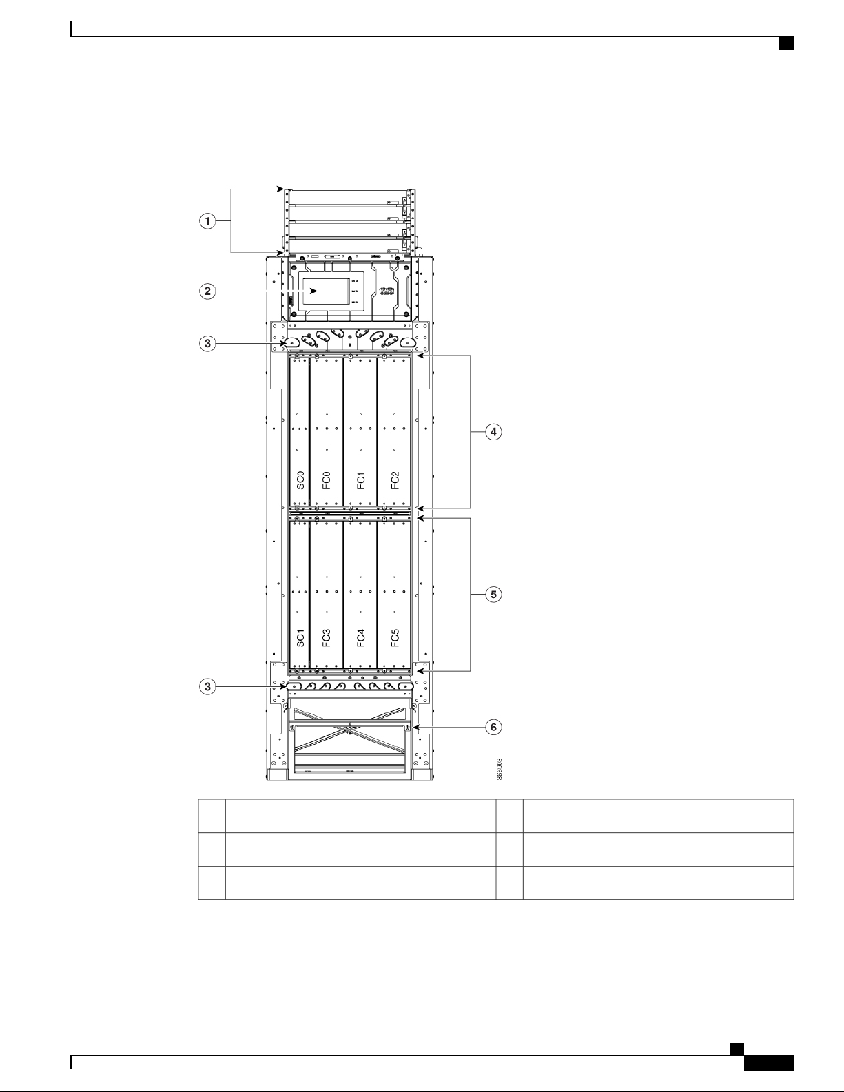
Overview
Fabric Card Chassis Components
The following figure shows the front view of the Cisco NCS 6000 FCC.
Figure 1: Front View of the Cisco NCS 6000 FCC
Upper card cage4Power enclosure1
Lower card cage5Craft panel display2
Removable air filter6Cable management brackets3
Cisco Network Convergence System 6000 Fabric Card Chassis Hardware Installation Guide
7
Page 22
Slot Numbers
Overview
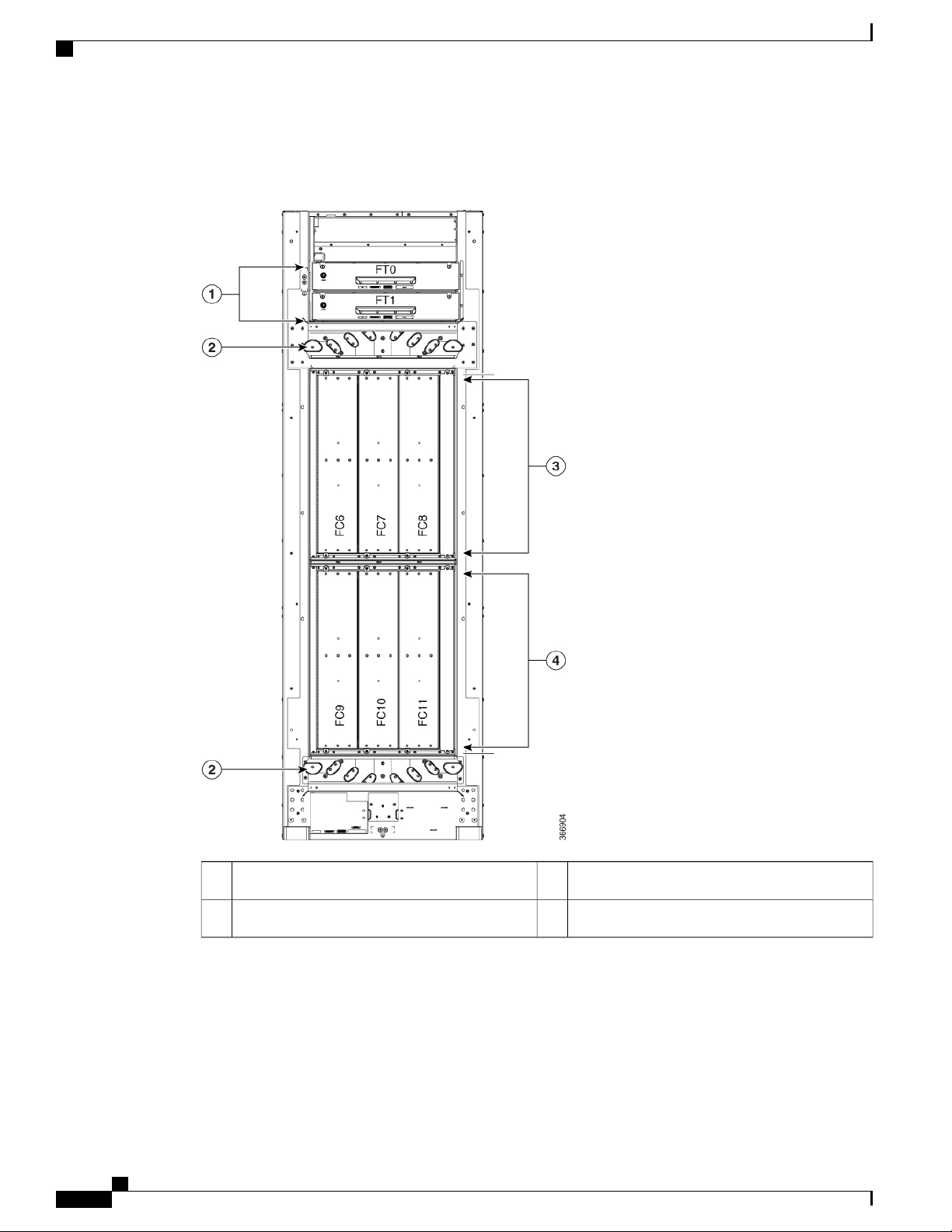
The following figure shows the rear view of the Cisco NCS 6000 FCC.
Figure 2: Rear View of the Cisco NCS 6000 FCC
Slot Numbers
This section identifies the location and slot numbers for system components that plug into the Cisco NCS
6000 FCC. The following figure shows the slot number locations on the front and rear of the LCC.
Cisco Network Convergence System 6000 Fabric Card Chassis Hardware Installation Guide
8
Upper card cage3Two fan trays1
Lower card cage4Cable management brackets2
Page 23
Overview
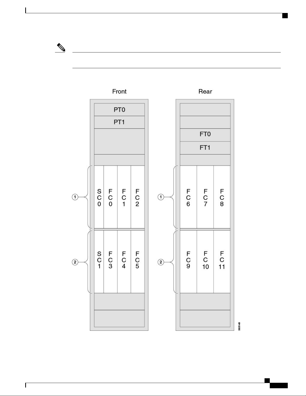
Slot Numbers
Note
The four power trays slots (PT0–PT3) are part of the power enclosure described in the About the Power
Enclosure, on page 13 section.
Figure 3: Cisco NCS 6000 FCC Slot Numbers
The FCC has the following slots:
Cisco Network Convergence System 6000 Fabric Card Chassis Hardware Installation Guide
9
Page 24

Cable Management
Front of the FCC
Four power trays for redundancy. The upper two power trays (PT0 and PT1) are referred to as power
•
shelf 0 (PS0) and the lower two power trays (PT2 and PT3) are referred to as power shelf 1 (PS1).
Two SC slots for redundancy (for SC and SC-SW cards) and six FC slots.
•
Upper card cage: (left to right: SC0, FC0, FC1, FC2)
◦
Lower card cage: (left to right: SC1, FC3, FC4, FC5)
◦
Rear of the FCC
Two fan trays for redundancy.
•
Upper fan tray: FT0
◦
Lower fan tray: FT1
◦
Six FC slots
•
Overview
Upper card cage: (left to right: FC6, FC7, FC8)
◦
Lower card cage: (left to right: FC9, FC10, FC11)
◦
Cable Management
The distribution of the slot locations on the Cisco NCS 6000 FCC allows for the large number of optic fiber
cables required for a fully-loaded routing system. Splitting the FCs front and back maximizes the space around
each connector and simplifies cable management.
The NCS 6000 FCC cable management features include:
Front and rear cable management brackets: One cable management bracket is located above the upper
•
card cage and one cable management bracket below the lower card cage (Figure 1: Front View of the
Cisco NCS 6000 FCC and Figure 2: Rear View of the Cisco NCS 6000 FCC ).
Vertical cable troughs: Four troughs, two on the front side of the FCC, and two on the rear side of the
•
FCC (Figure 14: Front Door Trough Hinges, Latches, and Retention Brackets and Figure 17: Rear Door
Trough Hinges, Latches, and Retention Brackets).
Safety Guidelines
Before performing any installation procedures, review the safety guidelines in this section to avoid injuring
yourself or damaging the equipment.
Note
Cisco Network Convergence System 6000 Fabric Card Chassis Hardware Installation Guide
10
Review the safety warnings listed in Regulatory Compliance and Safety Information for the Cisco Network
Convergence System 6000 Series Routers before installing, configuring, or troubleshooting any installed
card.
Page 25

Overview
Safety Guidelines
Note
Power off the PCM output switch and the power to the associated two power trays prior to removing a
power tray.
The following guidelines are for your safety and to protect equipment. The guidelines do not include all
hazards. Be alert.
Never attempt to lift an object that might be too heavy for you to lift by yourself.
•
Keep the work area clear and dust-free during and after installation. Do not allow dirt or debris to enter
•
into any laser-based components.
Keep tools and FCC components away from walk areas.
•
Do not wear loose clothing, jewelry, and other items that could get caught in the FCC while working
•
with the FCC and its components.
Use Cisco equipment in accordance with its specifications and product-usage instructions.
•
Do not work alone if potentially hazardous conditions exist.
•
Make sure your installation follows national and local electrical codes:
•
In the United States, National Fire Protection Association (NFPA) 70, United States National
◦
Electrical Code; in Canada, Canadian Electrical Code, part I, CSA C22.1.
In other countries, International Electrotechnical Commission (IEC) 60364, part 1 through part 7.
◦
Connect only a DC power source that follows the safety extra-low voltage (SELV) requirements in
•
UL/CSA/IEC/EN 60950-1 and AS/NZS 60590 to the DC input power system.
Make sure that you have a readily accessible two-poled disconnect device incorporated in the fixed
•
configuration wiring of a DC input power system.
Make sure that you provide short-circuit (overcurrent) protection as part of the building installation.
•
Preventing Electrostatic Discharge
Electrostatic discharge (ESD) damage, which can occur when electronic cards or components are improperly
handled, results in complete or intermittent failures. We recommend use of an ESD-preventive wrist strap
whenever you handle network equipment or one of its components.
To prevent ESD damage:
Always use an ESD-preventive wrist or ankle strap, and ensure that it makes good skin contact. Connect
•
the equipment end of the connection cord to an ESD jack or a bare metal surface on the FCC (ensure
that the FCC is grounded).
Handle a card by its ejector levers, when applicable, or its metal carrier only; avoid touching the board
•
or connector pins.
Place a removed card board side up on an antistatic surface or in a static-shielding bag. If you plan to
•
return the component to the factory, immediately place it in a static-shielding bag.
Avoid contact between a card and clothing. The wrist strap protects the board from only ESD voltage
•
on the body; ESD voltage on clothing can still cause damage.
Cisco Network Convergence System 6000 Fabric Card Chassis Hardware Installation Guide
11
Page 26
Safety Guidelines
Overview
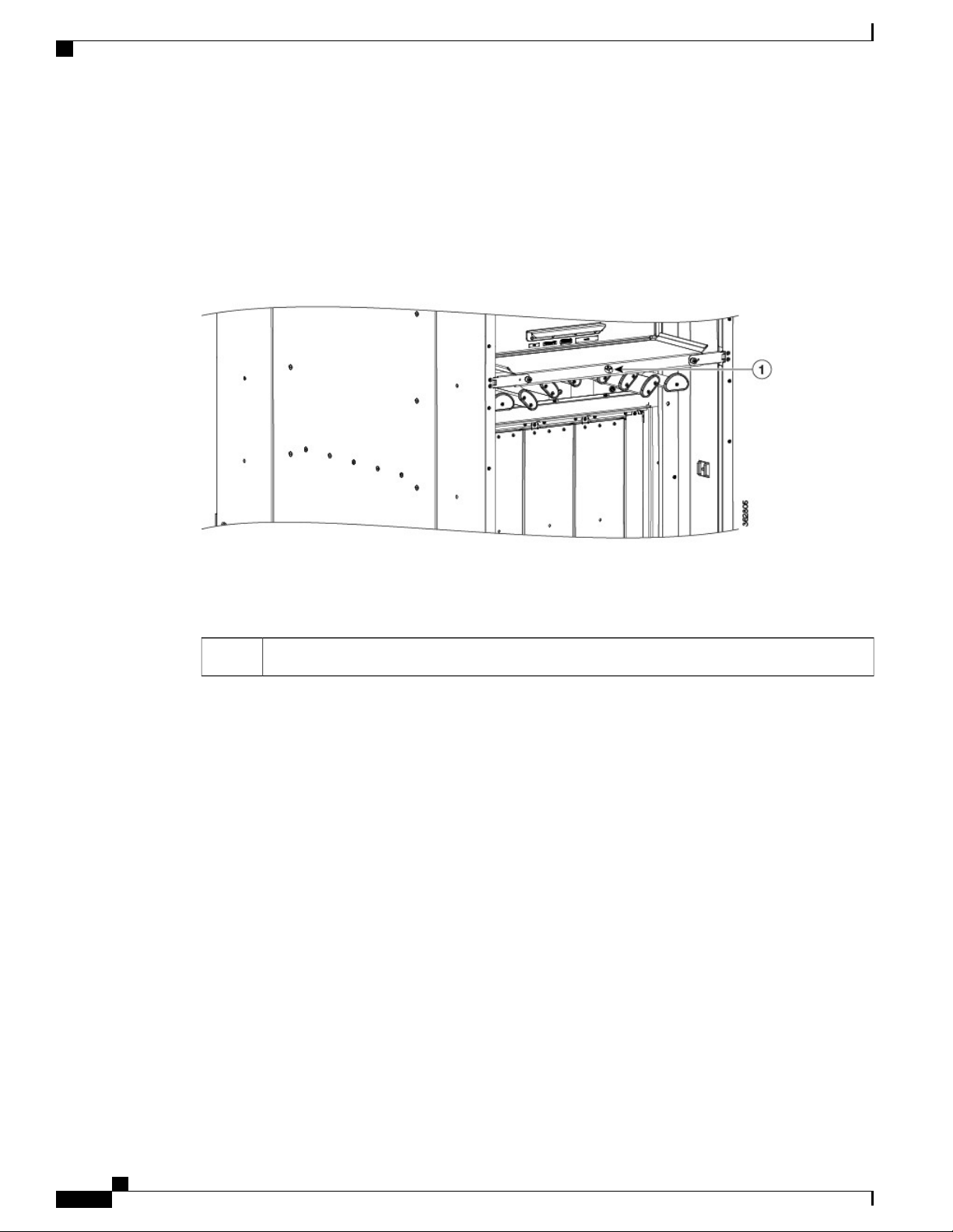
The following figure shows an example of the ESD jack on the FCC. An ESD jack is located directly above
the upper and lower cable management brackets on both sides of the FCC.
Figure 4: ESD Jack
ESD jack (two on each side of the FCC)1
Cisco Network Convergence System 6000 Fabric Card Chassis Hardware Installation Guide
12
Page 27

Installing the Power Enclosure, Power Trays, and Exterior Cosmetics
This chapter provides instructions on installing the Cisco NCS 6000 Fabric Card Chassis power enclosure,
power trays, and exterior cosmetics.
About the Power Enclosure, page 13
•
Installing the Power Trays, page 16
•
Installing the Exterior Cosmetics, page 20
•
About the Power Enclosure
The Cisco NCS 6000 FCC ships with a separate empty power enclosure (Cisco PID NCS-F-PWR-SHELF).
The power enclosure consists of one power shelf, four slots for AC or DC power trays, and two power control
modules (PCMs).
The upper two power trays (PT0 and PT1) are referred to as power shelf 0 (PS0), and the lower two power
trays (PT2 and PT3) are referred to as power shelf 1 (PS1) Figure 3: Cisco NCS 6000 FCC Slot Numbers.
Each set of power trays has a power control module (PCM) with its own I/O power switch. Three AC power
modules or four DC power modules can be installed in each power tray. See the Installing an AC or DC Power
Module , on page 46 section.
CHAPTER 3
Cisco Network Convergence System 6000 Fabric Card Chassis Hardware Installation Guide
13
Page 28

Installing the Power Enclosure
Installing the Power Enclosure, Power Trays, and Exterior Cosmetics
Note
Usually, it is not necessary to remove the power enclosure although it is field-serviceable. For information
about removing the power enclosure components, see the Replacing an AC or DC Power Tray, on page
99 section.
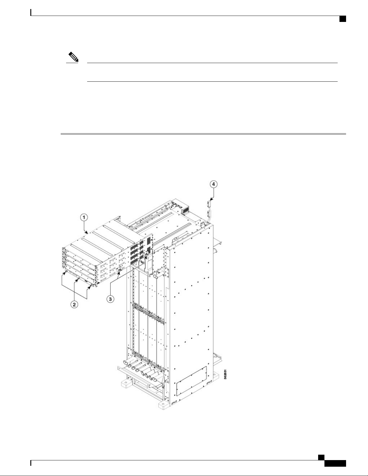
Figure 5: FCC Power Enclosure—Front and Rear Views
Two PCMs2
Installing the Power Enclosure
This section describes how to install the power enclosure in the Cisco NCS 6000 FCC.
Required Tools and Equipment
6-inch, Number-2 Phillips screwdriver
•
Power enclosure (Cisco PID NCS-F-PWR-SHELF)
•
Cisco Network Convergence System 6000 Fabric Card Chassis Hardware Installation Guide
14
PCM I/O power switches (one per PCM)3Four power tray slots for AC or DC power trays1
Page 29
Installing the Power Enclosure, Power Trays, and Exterior Cosmetics
Installing the Power Enclosure
Step 1
Note
The power enclosure weighs approximately 30 pounds and sits on top of the FCC. To prevent injury, we
recommend that you use a ladder and use two people when installing the power shelf.
Steps
Follow these steps to attach the power enclosure to the FCC:
Lift and place the power enclosure (busbar facing back) at the top of the FCC.
Caution
Figure 6: Attaching the Power Enclosure to the FCC
Handle the power shelf by lifting it at the sides and along the bottom of the shelf when installing it into the
FCC. Avoid lifting the shelf from the center bottom.
Cisco Network Convergence System 6000 Fabric Card Chassis Hardware Installation Guide
15
Page 30
Installing the Power Trays
Installing the Power Enclosure, Power Trays, and Exterior Cosmetics
Side captive screws (two per side)3Power enclosure1
D-Sub connector cables (one per PCM)4Three front captive screws2
Step 2
Step 3
Step 4
Step 5
Step 6
Step 7
Position and align the two rails on each side of the underside of the power enclosure with the two rails at the top of the
FCC. When the shelf is aligned properly, it will easily slide in place.
Slowly push the power enclosure forward until the front flange with the three captive screws engages with the front of
the FCC.
Loosely tighten the captive screws (two per side) on the power enclosure, and then loosely tighten the three captive
screws on the front flange.
Repeat Step 4, tightening all captive screws to firmly attach the power enclosure to the FCC.
Attach the two D-Sub connector cables to the two PCM connectors on back of the power enclosure and tighten the captive
screws on each cable connector. The individual PCMs are labeled PCM0 and PCM1.
Tighten the captive screws on each cable connector.
Installing the Power Trays
This section describes how to install an AC or DC power tray in the power enclosure and includes the following
topics:
Note
Although there are differences between AC and DC power trays, they are installed by using the same
procedures described in this section. Once they are installed into an FCC that is properly grounded, external
grounding to the power tray is not needed.
About the AC and DC Power Trays
The Cisco NCS 6000 FCC power enclosure supports either four AC power trays or four DC power trays. An
AC power tray houses up to three AC power modules, while a DC power tray houses up to four DC power
modules. See the Installing an AC or DC Power Module , on page 46 section.
Note
Cisco Network Convergence System 6000 Fabric Card Chassis Hardware Installation Guide
16
Only one type of power tray can be installed in the power enclosure. You cannot mix AC and DC power
trays.
Page 31

Installing the Power Enclosure, Power Trays, and Exterior Cosmetics
About the AC and DC Power Trays
Note
For a DC power tray, the rear input LED starts to light up when the input voltage reaches -20 VDC, gets
brighter as the voltage increases, and is fully lit when the input voltage reaches -48 VDC.
Figure 7: AC Power Tray—Front View
Figure 8: AC Power Tray—Rear View (Clear Plastic Safety Cover Removed)
Figure 9: DC Power Tray—Front View
Cisco Network Convergence System 6000 Fabric Card Chassis Hardware Installation Guide
17
Page 32

Installing an AC or DC Power Tray
Figure 10: DC Power Tray—Rear View (Clear Plastic Safety Cover Removed)
Installing the Power Enclosure, Power Trays, and Exterior Cosmetics
Installing an AC or DC Power Tray
This section describes how to install an AC or DC power tray in the Cisco NCS 6000 FCC.
Note
Prerequisites
Cisco Network Convergence System 6000 Fabric Card Chassis Hardware Installation Guide
18
For information about removing a power tray, see the Replacing an AC or DC Power Tray, on page 99
section.
Before you install an AC or DC power tray, do the following:
Remove the top grilles from both the front and rear sides of the FCC, if installed.
•
Ensure the power tray you are about to install is empty. Do not install a power tray into the FCC with
•
the PMs installed in the power tray.
Page 33

Installing the Power Enclosure, Power Trays, and Exterior Cosmetics
Required Tools and Equipment
Four M4 x 10 mm screws per power tray
•
6-inch, Number-2 Phillips screwdriver
•
Number-2 Phillips torque screwdriver with torque rated up to 55 in-lb (6.2 N-m)
•
AC or DC power tray
•
AC power tray (Cisco PID NCS-AC-PWRTRAY)
◦
DC power tray (Cisco PID NCS-DC-PWRTRAY)
◦
Steps
To install an AC or DC power tray, follow these steps:
Installing an AC or DC Power Tray
Step 1
Step 2
Using two people, one to support the power tray underneath and the other to keep it steady, lift the power tray up and
slide it partially into a power tray slot on the power enclosure.
Caution
Because of the weight of a power tray, 20 lb (9 kg), and the height at which a power tray is installed in the
FCC, be especially careful while removing and carrying a power tray. To prevent injury, avoid sudden twists
or lateral moves.
Grasping both handles simultaneously, push both the left and right handles in at the same time to push the tray into the
power enclosure. Slide the tray all the way into the enclosure until both power tray handles engage the slots.
Cisco Network Convergence System 6000 Fabric Card Chassis Hardware Installation Guide
19
Page 34

Installing the Exterior Cosmetics
Installing the Power Enclosure, Power Trays, and Exterior Cosmetics
Caution
Figure 11: Installing a Power Tray into the Power Enclosure—DC Power Tray Shown
Use care not to bend the
handles.
Step 3
Step 4
Use the screwdriver to loosely tighten the four M4 x 10 mm screws that attach the power tray to the power enclosure.
Use the torque screwdriver to tighten the four screws to a torque value of 15 in-lb (1.69 N-m) to 20 in-lb (2.26 N-m).
The screws that attach a power tray to the power shelf are relied upon for power tray bonding and grounding.Note
Installing the Exterior Cosmetics
This section describes how to install the exterior cosmetics on the Cisco NCS 6000 FCC and includes the
following topics:
For information about removing the external cosmetics, see the Removing the Exterior Cosmetics , on page
87 section.
Cisco Network Convergence System 6000 Fabric Card Chassis Hardware Installation Guide
20
Page 35

Installing the Power Enclosure, Power Trays, and Exterior Cosmetics
Overview of the Exterior Cosmetics
The Cisco NCS 6000 FCC is shipped with exterior cosmetics for the front side and rear side of the FCC.
Figure 12: Exterior Cosmetics—Front Side of the FCC
Overview of the Exterior Cosmetics
Bottom grille3Top grille1
Front door2
Cisco Network Convergence System 6000 Fabric Card Chassis Hardware Installation Guide
21
Page 36

Installing the Front Exterior Cosmetics
Figure 13: Exterior Cosmetics—Rear Side of the FCC
Installing the Power Enclosure, Power Trays, and Exterior Cosmetics
Rear exhaust air deflector1
Rear door2
Installing the Front Exterior Cosmetics
This section describes how to install the front side exterior cosmetics on the Cisco NCS 6000 FCC. We
recommend that you install the exterior cosmetics in the order outlined in this section.
Note
Cisco Network Convergence System 6000 Fabric Card Chassis Hardware Installation Guide
22
Before performing these tasks, you must first unpack and secure the chassis. See the Cisco Network
Convergence System 6000 Series Routers Unpacking, Moving, and Securing Guide.
Page 37

Installing the Power Enclosure, Power Trays, and Exterior Cosmetics
Prerequisites
Installing the Power Enclosure , on page 14
Required Tools and Equipment
8-inch, Number-1 Phillips screwdriver (magnetic head preferable)
•
Two vertical cable troughs (left and right troughs are interchangeable)
•
Three door hinges
•
Three door latches
•
Four trough retention brackets
•
Front door
•
Door grounding cable
•
Installing the Front Exterior Cosmetics
Step 1
Step 2
Craft panel cover
•
Front top grille
•
Front bottom grille
•
For information on the cosmetic PID numbers, see Cosmetic Product IDs, on page 134.
Steps
To install the front exterior cosmetics, follow these steps:
Remove the upper and lower horizontal cable management brackets (preinstalled on the FCC) by loosening and removing
the eight pan-head screws (four per bracket). One bracket is located above the upper card cage and the other bracket is
below the lower card cage.
Attach the left and right vertical cable troughs to the front of the FCC. The two vertical cable troughs are installed inverted
from each other. Each trough is marked FRONT to ensure that you install the trough on the correct side of the FCC.
Cisco Network Convergence System 6000 Fabric Card Chassis Hardware Installation Guide
23
Page 38

Installing the Front Exterior Cosmetics
Installing the Power Enclosure, Power Trays, and Exterior Cosmetics
Note
We recommend that you use two people to attach the vertical cable troughs; one person to hold the vertical
cable troughs in place while the other person inserts and tightens the screws.
Figure 14: Front Door Trough Hinges, Latches, and Retention Brackets
1
Trough retention brackets (two per trough)4Vertical cable troughs (one per side), each attached
to the FCC with eight pan-head screws
Two horizontal cable management brackets
5Three door hinges2
(preinstalled)
Cisco Network Convergence System 6000 Fabric Card Chassis Hardware Installation Guide
24
Page 39

Installing the Power Enclosure, Power Trays, and Exterior Cosmetics
Installing the Front Exterior Cosmetics
Step 3
Step 4
Step 5
3
Craft panel display cover6Three door latches:
Door stop latch, top and bottom (700-39150-01)
Door latch, middle (700-46854-01)
For each vertical cable trough
Align the guide pins on the rear of the vertical cable trough with the positioning holes on the front of the FCC.
1
Loosely insert eight pan-head screws, and then use the screwdriver to tighten them clockwise to attach the vertical
2
cable troughs firmly to the front of the FCC. You might need to use a ladder to reach the upper screws.
Attach two trough retention brackets to each vertical trough with two 8-32 flat-head screws (two per trough).
3
Using the captive screw, insert the trough retention brackets into each upper and lower horizontal cable troughs (two
4
screws per side).
Reattach the upper and lower horizontal cable management brackets by inserting and tightening the eight pan-head
screws (four per bracket).
Attach the three door hinges and the three door latches by using two pan-head screws each.
Align the front door (see the following figure) with the three door hinges on the FCC. The door will then drop into
position onto the hinge attachment pins.
Cisco Network Convergence System 6000 Fabric Card Chassis Hardware Installation Guide
25
Page 40

Installing the Front Exterior Cosmetics
We recommend that you use two people to lift the door onto the FCC.Note
Figure 15: Attaching the Front Door
Installing the Power Enclosure, Power Trays, and Exterior Cosmetics
Grounding cable3Front door1
Door hinges2
Cisco Network Convergence System 6000 Fabric Card Chassis Hardware Installation Guide
26
Page 41

Installing the Power Enclosure, Power Trays, and Exterior Cosmetics
Installing the Front Exterior Cosmetics
Step 6
Step 7
Attach the grounding cable to the front door.
a) Insert and tighten one pan-head screw to attach one end of the ground cable to the inside of the door.
b) Insert and tighten one pan-head screw to attach the other end of the ground cable to the vertical cable trough.
Attach the grilles to the troughs (see the following figure).
a) Attach the top grille by carefully inserting the bottom tabs into the slots on the bottom of the grille Press the grille
firmly against the troughs until the snap joiners on the top of the grill snap into place.
b) Attach the bottom grille by carefully inserting the top tabs into the slots on the top of the grille. Press the grille firmly
against the troughs until the snap joiners on the bottom of the grille snaps into place.
Figure 16: Front Grilles
Front bottom grille2Front top grille1
Cisco Network Convergence System 6000 Fabric Card Chassis Hardware Installation Guide
27
Page 42

Installing the Rear Exterior Cosmetics
Installing the Rear Exterior Cosmetics
This section describes how to install the rear side exterior cosmetics on the Cisco NCS 6000 FCC. We
recommend that you install the exterior cosmetic components in the order outlined in this section.
Prerequisites
Installing the Power Enclosure , on page 14
Installing the Front Exterior Cosmetics, on page 22
Required Tools and Equipment
Installing the Power Enclosure, Power Trays, and Exterior Cosmetics
Step 1
Step 2
8-inch, Number-1 Phillips screwdriver (magnetic head preferable)
•
Two vertical cable troughs (left and right are interchangeable)
•
Three door hinges
•
Three door latches
•
Four trough retention brackets
•
Exhaust plenum bracket
•
Rear door
•
Door grounding cable
•
Rear exhaust air deflector
•
Steps
To install the rear exterior cosmetics, follow these steps:
Remove the upper and lower horizontal cable management brackets (preinstalled on the FCC) by loosening and removing
the eight pan-head screws (four per bracket). One bracket is located above the upper card cage and the other bracket is
below the lower card cage.
Attach the left and right vertical cable troughs to the rear of the FCC. The two vertical cable troughs are inverted from
each other. Each trough is marked REAR to ensure that you install the trough on the correct side of the FCC.
Cisco Network Convergence System 6000 Fabric Card Chassis Hardware Installation Guide
28
Page 43

Installing the Power Enclosure, Power Trays, and Exterior Cosmetics
Installing the Rear Exterior Cosmetics
Note
We recommend that you use two people to attach the vertical cable troughs; one person to hold the vertical
cable troughs in place while the other person inserts and tightens the screws
Figure 17: Rear Door Trough Hinges, Latches, and Retention Brackets
1
to the FCC with eight pan-head screws
Cisco Network Convergence System 6000 Fabric Card Chassis Hardware Installation Guide
Trough retention brackets (two per trough)4Vertical cable troughs (one per side), each attached
Two horizontal cable troughs (preinstalled)5Three door hinges2
29
Page 44

Installing the Power Enclosure, Power Trays, and Exterior Cosmetics
Installing the Rear Exterior Cosmetics
Three door latches:
3
Door stop latch, top and bottom (700-39150-01)Door
latch, middle (700-46854-01)
For each vertical cable trough:
a) Align the guide pins on the rear of the vertical cable trough with the positioning holes on the rear of the chassis.
b) Loosely insert eight pan-head screws, and then use the screwdriver to tighten them clockwise to attach the vertical
cable troughs firmly to the front of the FCC. You might need to use a ladder to reach the upper screws .
c) Attach the trough retention brackets to each vertical trough with two 8-32 flat-head screws (two per trough).
d) Using the captive screw, insert the trough retention brackets into each upper and lower horizontal cable troughs on
the FCC (two screws per side).
Step 3
Step 4
Reattach the upper and lower horizontal cable management brackets by inserting and tightening the eight pan-head
screws (four per bracket).
Attach the side filler panels.
For each filler panel:
a) Align the guide pins on the filler panel with the positioning holes on top of the FCC.
b) Insert the filler panel into the FCC and slide it down until it is fully seated.
Cisco Network Convergence System 6000 Fabric Card Chassis Hardware Installation Guide
30
Page 45

Installing the Power Enclosure, Power Trays, and Exterior Cosmetics
c) Loosely attach the filler panel to the FCC with two 8-32 screws.
Figure 18: Side Filler Panels
Installing the Rear Exterior Cosmetics
Two 8-32 screws3Side filler panel (one each side)1
Guide pins2
Cisco Network Convergence System 6000 Fabric Card Chassis Hardware Installation Guide
31
Page 46

Installing the Rear Exterior Cosmetics
Installing the Power Enclosure, Power Trays, and Exterior Cosmetics
Step 5
Step 6
Attach the exhaust plenum bracket to the FCC (cutouts facing up) using six pan-head screws, three screws each side.
Before installing the bracket, remove the topmost screw on each of the vertical troughs.
Tighten the two 8-32 screws on the filler panel (that you previously installed) securely to the FCC.
Figure 19: Exhaust Plenum Bracket
Six pan-head screws (three per side)2Exhaust plenum bracket1
Step 7
Step 8
Step 9
Attach the three door hinges and the three door latches by using two pan-head screws each (Figure 17: Rear Door Trough
Hinges, Latches, and Retention Brackets).
Align the rear door with the three door hinges on the FCC (Figure 15: Attaching the Front Door). The door will then
drop into position onto the hinge attachment pins.
We recommend that you use two people to lift the door onto the FCC.Note
Attach the grounding cable to the rear door (step 7).
a) Insert and tighten one pan-head screw to attach one end of the ground cable to the inside of the door.
Cisco Network Convergence System 6000 Fabric Card Chassis Hardware Installation Guide
32
Page 47

Installing the Power Enclosure, Power Trays, and Exterior Cosmetics
b) Insert and tighten one pan-head screw to attach the other end of the ground cable to the vertical cable trough.
Installing the Rear Exterior Cosmetics
Step 10
Attach the exhaust air deflector by carefully inserting its mounting tabs into the exhaust plenum brackets. Press the
deflector firmly against the vertical cable troughs until it snaps on.
Figure 20: Exhaust Air Deflector—Rear of the Chassis
Exhaust air deflector1
Cisco Network Convergence System 6000 Fabric Card Chassis Hardware Installation Guide
33
Page 48

Installing the Rear Exterior Cosmetics
Installing the Power Enclosure, Power Trays, and Exterior Cosmetics
Cisco Network Convergence System 6000 Fabric Card Chassis Hardware Installation Guide
34
Page 49

Installing the Power Components
This chapter provides an overview of the AC and DC power systems and how to install the power modules
and input power cables into the Cisco NCS 6000 Fabric Card Chassis (FCC). For information about removing
power components, see the Removing the Power Components, on page 96 section.
Power System Overview, page 35
•
Installing the Power Modules and Input Power Cables, page 45
•
Powering On and Powering Off the Fabric Card Chassis, page 57
•
Power System Overview
The Cisco NCS 6000 FCC can be configured with either an AC input power system or a DC input power
system. Site power requirements differ, depending on the source voltage used.
For information about power safety requirements, see the Regulatory Compliance and Safety Information for
the Cisco Network Convergence System 6000 Series Routers.
CHAPTER 4
Prerequisites
Follow these precautions and recommendations when planning power connections to the FCC:
Check the power at your site before installation to ensure that you are receiving clean power (free of
•
spikes and noise). Install a power conditioner, if necessary.
Install proper grounding to avoid damage from lightning and power surges.
•
Installing the Fabric Card Chassis Ground Cable
The FCC has two safety earth ground connections. You can connect the central office ground system or interior
equipment grounding system to either of these grounding points on the rear side of the FCC. One chassis
ground is located near the top of the FCC and one chassis ground is located at the bottom of the FCC. These
Cisco Network Convergence System 6000 Fabric Card Chassis Hardware Installation Guide
35
Page 50

Installing the Fabric Card Chassis Ground Cable
grounding points are also referred to as Network Equipment Building System (NEBS) bonding and grounding
point, and are provided to satisfy the Telcordia NEBS safety requirements.
Figure 21: NEBS Bonding and Grounding Points—Rear Side of the FCC
Installing the Power Components
Do not remove the FCC ground cable unless the FCC is being replaced.Caution
Required Tools and Equipment
You will need to provide the following tools and equipment:
Number-2 Phillips screwdriver
•
Ground lug
•
Ground cable
•
Cisco Network Convergence System 6000 Fabric Card Chassis Hardware Installation Guide
36
NEBS bonding and grounding point (lower)2NEBS bonding and grounding points (upper)1
Page 51

Installing the Power Components
•
•
To ensure a satisfactory ground connection:
•
•
•
Installing the Fabric Card Chassis Ground Cable
Crimping tool and lug specific die
3/8-inch drive torque wrench rated to include 30 in-lb (3.39 N-m)
One 180-degree angle (straight) grounding lug that has two M6 bolt holes with 0.63 inch (16 mm)
spacing center to center between them, and a wire receptacle able to accept a 2-6-AWG multistrand
copper wire.
Two M6 bolts with integrated square cone locking washers (shipped pre-installed on the FCC, two at
each grounding point).
2-6-AWG multistrand copper ground cable. This cable is not available from Cisco; it is available from
any commercial cable vendor such as Panduit (see http://www.panduit.com). The cable should be sized
according to local and national installation requirements.
Note
The DC return of this system should remain isolated from the system frame and FCC (DC-I: Isolated DC
Return).
Figure 22: 180-Degree Angle Straight Barrel Grounding Lug
Cisco Network Convergence System 6000 Fabric Card Chassis Hardware Installation Guide
37
Page 52

Installing the Fabric Card Chassis Ground Cable
Steps
To attach the ground cable to the FCC, follow these steps:
Installing the Power Components
Step 1
Step 2
Use the crimping tool mandated by the lug manufacturer to crimp the lug to the ground cable.
Use the socket wrench to attach the lug and ground cable to one the NEBS grounding point (Figure 21: NEBS Bonding
and Grounding Points—Rear Side of the FCC ).
Figure 23: Attaching the Ground Cable to a NEBS Bonding and Grounding Point
Step 3
Step 4
38
Use the torque wrench to tighten the bolts to a torque of 30 in-lb (3.39 N-m).
Connect the other end of the ground cable to a grounding point at your site, according to site requirements.
Cisco Network Convergence System 6000 Fabric Card Chassis Hardware Installation Guide
Page 53

Installing the Power Components
AC Power System
Overview of the AC Power System
An AC-powered Cisco NCS 6000 FCC contains four AC power trays that are part of the FCC power enclosure
(Figure 5: FCC Power Enclosure—Front and Rear Views). The upper two power trays (PT0 and PT1) are
referred to as PS0, and the lower two power trays (PT2 and PT3) are referred to as PS1. Figure 3: Cisco NCS
6000 FCC Slot Numbers. Each set of power trays has a power control module (PCM) with its own I/O power
switch.
Each AC power tray has three slots for PMs. The AC power trays are field-replaceable (after power down),
however the PMs are hot-swappable.
Each inserted AC PM requires a single-phase, 50 to 60 Hz, 200 to 240 VAC input. Input current is variable
and based on facility minimum voltage. For N+N redundancy, power feeds A must power the upper two AC
power trays and power feeds B must power the lower two AC power trays (not all of the power module bays
need to be filled). This allows the system to balance its load across each set of power trays and across the
power modules within each tray.
The AC power system requires single-phase AC input power to each inserted PM. If you have a 3-phase AC
Delta or AC Wye at your equipment, a Cisco NCS power distribution unit (PDU) is required to convert
3-phase AC input power to single-phase AC input power system.
AC Power System
Note
Note
If you plan to use a three-phase AC PDU we recommend that you install three AC PMs in each AC power
tray to maintain a balanced three-phase power load.
We recommend that you use appropriate short-circuit protection in compliance with national and local
electrical codes.
Installing an AC Power Distribution Unit
The AC PDU converts three-phase AC input power to single-phase AC input power that connects directly to
the rear of each PM. The AC PDU includes either an AC Delta (Cisco PID NCS-PDU-DELTA) or AC Wye
Cisco Network Convergence System 6000 Fabric Card Chassis Hardware Installation Guide
39
Page 54

AC Power System
Installing the Power Components
(Cisco PID NCS-PDU-WYE) power interface, and has power input and power output cords entering and
exiting the box.
Figure 24: Cisco NCS-PDU
For detailed information on AC PDUs, see the Cisco CRS 3-Phase AC Power Distribution Unit Installation
Guide.
Mounting the PDU
The AC PDU mounting bracket holds two AC PDUs. The mounting bracket can be attached to both sides of
the FCC by using the existing screws that hold the side panels on (Figure 25: AC PDU Bracket Attached to
the Side of the FCC). The PDUs are attached to the mounting brackets with four M5 screws per AC PDU.
Output cord4Rack mounting ears1
Two PDUs5Rack tray2
Input cord3
Cisco Network Convergence System 6000 Fabric Card Chassis Hardware Installation Guide
40
Page 55

Installing the Power Components
Optionally, you can mount the AC PDU in an external 19-inch rack by using six pan-head screws (Figure 26:
Rack Mounting the AC PDU in a 19-Inch Rack).
Figure 25: AC PDU Bracket Attached to the Side of the FCC
AC Power System
PDU bracket (chassis mount)2AC PDUs (one each side)1
Cisco Network Convergence System 6000 Fabric Card Chassis Hardware Installation Guide
41
Page 56

AC Power System
Installing the Power Components
Figure 26: Rack Mounting the AC PDU in a 19-Inch Rack
Installing the Tie-Down Bar
A 19-inch tie-down bar can be used to add strain relief for input power cables from the AC PDUs or cables
routed from a raised floor. The following figure shows holes for two 10-32 x 0.50 inch screws that are
pre-drilled on the FCC for attaching a tie-down bar.
Cisco Network Convergence System 6000 Fabric Card Chassis Hardware Installation Guide
42
Page 57

Installing the Power Components
DC Power System
Note
The 19-inch tie-down bar and screws are not supplied by Cisco. You can order these parts from a
commercial vendor such as Panduit.
Figure 27: 19-Inch Tie-Down Bar
DC Power System
A DC-powered Cisco NCS 6000 FCC contains four DC power trays that are part of the FCC power enclosure
(Figure 5: FCC Power Enclosure—Front and Rear Views). The upper two power trays (PT0 and PT1) are
referred to as power shelf 0 (PS0), and the lower two power trays (PT2 and PT3) are referred to as power
shelf 1 (PS1). Figure 3: Cisco NCS 6000 FCC Slot Numbers. Each set of power trays has a power control
module (PCM) with its own I/O power switch.
The DC power tray has four slots for PMs. The DC power trays are field-replaceable (after power down),
however the PMs are hot-swappable.
For N+N redundancy, “A” power feeds must power the upper two DC power trays and “B” power feeds must
power the lower two DC power trays (not all of the PM bays need to be filled). This allows the system to
balance its load across the two set of power trays and across the power modules within each tray.
The following table lists the DC input current and voltage specifications.
Tie-down bar1
Cisco Network Convergence System 6000 Fabric Card Chassis Hardware Installation Guide
43
Page 58

DC Power System
Installing the Power Components
Table 4: DC Input Current and Voltage Information
Note
Nominal input voltage
Input line current
–48 VDC or –60 VDC (tolerance range: –40 to –72 VDC)
50 A maximum at –48 VDC
40 A maximum at –60 VDC
60 A maximum at –40 VDC
Each wiring block on the DC power tray contains two sets of terminals, one positive and one negative, and
is covered by a plastic terminal block cover that is secured by a screw to a torque of 5 to 7 in-lb (0.56 to 0.79
N-m). Each DC power cable is connected to a power tray with a torque of 45 to 55 in-lb (5.1 to 6.2 N-m).
The terminal block supports 4-6-AWG input wire.
The cable should be sized according to local and national installation requirements. Use only copper cable.
An “allpole” separation of the power source is not required. The DC PM is an isolated DC/DC converter
with no galvanic connection between “L+” and the FCC. In addition, the “L+” potentials of each PM are
isolated from each other.
Cisco Network Convergence System 6000 Fabric Card Chassis Hardware Installation Guide
44
Page 59

Installing the Power Components
The power supply terminal posts are centered 0.63 inches (16 mm) apart and are 1/4-20 thread. We recommend
that you use an appropriately sized 90-degree angle, industry-standard, dual-hole, standard barrel compression
lug.
Figure 28: 90-Degree Angle Standard Barrel Compression Lug
Installing the Power Modules and Input Power Cables
Installing the Power Modules and Input Power Cables
This section describes how to install the power modules and AC and DC power cables in the Cisco NCS 6000
FCC. We recommend that you perform the installation in the order outlined in this section.
Cisco Network Convergence System 6000 Fabric Card Chassis Hardware Installation Guide
45
Page 60

Installing an AC or DC Power Module
Installing the Power Components
Note
Ensure that the ground cable is installed on the FCC before you install the power modules and input power
cables. See the Installing the Fabric Card Chassis Ground Cable, on page 35.
Installing an AC or DC Power Module
This section describes how to install an AC or DC power module (PM) into the power trays in the Cisco NCS
6000 FCC. Although there are differences between the AC and DC PMs, they are installed by using the same
procedures.
Note
An AC-powered FCC supports up to 12 AC PMs (three per power tray). A DC-powered FCC supports
up to 16 DC PM (four per power tray).
Cisco Network Convergence System 6000 Fabric Card Chassis Hardware Installation Guide
46
Page 61

Installing the Power Components
Each PM has three status LEDs located on the front left side of its faceplate (Figure 34: AC and DC Power
Module Power Module Status Indicators). See Table 5: Power Module LED Status Indicator Lights for the
meaning of each status LED.
Figure 29: AC Power Module—Front View
Installing an AC or DC Power Module
Figure 30: AC Power Module—Rear View
Figure 31: DC Power Module—Front View
Cisco Network Convergence System 6000 Fabric Card Chassis Hardware Installation Guide
47
Page 62

Installing an AC or DC Power Module
Figure 32: DC Power Module—Rear View
Installing the Power Components
Prerequisites
Installing the Exterior Cosmetics, on page 20
•
Installing the Fabric Card Chassis Ground Cable, on page 35
•
Caution
Do not install a power module into an AC or DC power tray until the power tray is securely screwed into
the power enclosure.
Required Tools and Equipment
ESD-preventive wrist strap
•
6-inch, Number1 Phillips-head screwdriver
•
Cisco Network Convergence System 6000 Fabric Card Chassis Hardware Installation Guide
48
Page 63

Installing the Power Components
•
•
Steps
Power modules are keyed to prevent incorrect insertion into the power tray.Note
To install a PM into a power tray, follow these steps:
Installing an AC or DC Power Module
Torque screwdriver with Number-1 Phillips bit and rated torque at 5.5 in-lb (0.62 N-m)
AC or DC PM
AC PM (Cisco PID PWR-3KW-AC-V2)
◦
DC PM (Cisco PID PWR-2KW-DC-V2)
◦
Step 1
Step 2
Attach the ESD-preventive wrist strap to your wrist and connect its leash to the ESD jack on the front side of the FCC
(see Preventing Electrostatic Discharge, on page 11). You can also connect the ESD-preventive wrist strap leash to any
bare metal surface on the FCC.
Use two hands to support and guide the PM, and then slide it into the power tray.
Note
Though a PM can be inserted into any empty PM bay in any power tray, during the initial installation, install a
PM into PM0 in PT0 first. Next, install PMs in ascending order into the remaining PM bays in PT0. Then, install
PMs in ascending order into the remaining power trays.
Cisco Network Convergence System 6000 Fabric Card Chassis Hardware Installation Guide
49
Page 64

About the Power Module Status Indicators
Installing the Power Components
Step 3
Step 4
Rotate the ejector lever upwards to seat the PM into the power tray.
Tighten the ejector lever screw to a nominal installation torque of 5.5 in-lb (0.62 N-m). Do not exceed a maximum
installation torque of 10 in-lb (1.13 N-m).
Figure 33: Installing a Power Module into a Power Tray—DC Power Tray Shown
Ejector lever2
Step 5
Step 6
Fill the power tray, in PM ascending order, to the required configuration.
If necessary, repeat these steps for the remaining power trays.
About the Power Module Status Indicators
The input-power-present LED on the AC and DC power modules provide a visual indication that voltage is
present across the input terminal connection.
For DC power modules, the DC input LED lights up when the input voltage reaches within the acceptable
•
range.
For AC power modules, the AC Input LED lights up when the input voltage reaches within the acceptable
•
range.
Ejector lever screw3Power module1
Cisco Network Convergence System 6000 Fabric Card Chassis Hardware Installation Guide
50
Page 65

Installing the Power Components
Always disconnect power servicing the input power connection.Note
About the Power Module Status Indicators
Caution
If the input voltage polarity is reversed, or if the LED circuit fails, the LED will not light. In this case,
service personnel should check for hazardous voltages before working on the system.
Figure 34: AC and DC Power Module Power Module Status Indicators
Fault LED3Input OK LED1
Output OK LED2
Cisco Network Convergence System 6000 Fabric Card Chassis Hardware Installation Guide
51
Page 66

Installing an AC or DC Power Module Slot Cover
Table 5: Power Module LED Status Indicator Lights
Installing the Power Components
MeaningColorLED Name
GreenInput OK
GreenOutput OK
RedFault
On: The input voltage is present and within regulation range.
Blinking: The input voltage is present but out of regulation range.
Off: The input voltage is not present.
On: The output voltage is on.
Blinking: The PM is in a power limit or Over Current condition.
Off: The output voltage is off.
On: An internal fault is detected within the PM.
Off: No internal faults detected on the PM.
Installing an AC or DC Power Module Slot Cover
This section describes how to install a PM slot cover into an empty PM slot on an AC or DC power tray.
Prerequisites
Before performing this task, you must remove the cosmetic grilles and install the PMs to the required
configuration in each power tray.
Required Tools and Equipment
ESD-preventive wrist strap
•
AC or DC PM slot cover (Cisco PID A9K-PEM-V2-FILR)
•
Cisco Network Convergence System 6000 Fabric Card Chassis Hardware Installation Guide
52
Page 67

Installing the Power Components
Steps
To install a PM slot cover in an AC or DC power tray, follow these steps:
Installing AC Input Power Cords
Step 1
Step 2
Step 3
Step 4
Attach the ESD-preventive wrist strap to your wrist and connect its leash to the ESD jack on the front side of the FCC
(see Preventing Electrostatic Discharge, on page 11). You can also connect the ESD-preventive wrist strap leash to any
bare metal surface on the FCC.
Align the PM slot cover with the empty PM slot in the power tray.
Insert the two tabs on the top of the PM slot cover into the two holes on the top of the PM slot.
Push in the top of the PM slot cover gently until it clicks into place.
Figure 35: PM Slot Cover on the Front of a Power Tray—DC Power Tray Shown
Installing AC Input Power Cords
This section describes how to connect the AC input power cords to the power modules and includes the
following topics:
Prerequisites
Ensure that there is a readily accessible disconnect device incorporated in the building's installation wiring.
Caution
Before connecting AC input power cords to the power system, make sure that the input power cords are
not energized.
Cisco Network Convergence System 6000 Fabric Card Chassis Hardware Installation Guide
53
Page 68

Installing AC Input Power Cords
Installing the Power Components
Caution
The circuit breaker and fuse lockout procedures should follow the rules and regulations in the National
Electrical Code (NEC) and any local codes.
Note
The AC power system requires single-phase AC input power to each PM. If you have 3-phase AC Delta
or AC Wye at your equipment, a Cisco NCS 6000 Series power distribution unit (PDU) is required to
convert 3-phase AC input power to single-phase AC input power (Cisco PID NCS-PDU-DELTA or Cisco
PID NCS-PDU-WYE). For more information, see the Cisco CRS 3-Phase AC Power Distribution Unit
Installation Guide.
Required Tools and Equipment
6-inch, Number 1 Phillips-head screwdriver
•
• AC input power cords, depending on the locale (Appendix B, “System Product IDs.”)
Steps
To install the AC input power cords, follow these steps:
Step 1
Step 2
On the rear of the FCC, insert the cord plug into the cord clamp following the labeling on the phase assignments from
the PDU or the labeling on the single-phase power cords.
Use the screwdriver to secure the screw that clamps the cord plug in place.
Figure 36: AC Input Power Cords Connected to the Power Tray
Cisco Network Convergence System 6000 Fabric Card Chassis Hardware Installation Guide
54
Page 69

Installing the Power Components
Installing DC Input Power Cables
This section describes how to connect the DC input power cables and install DC terminal block covers. The
DC terminal block cover is one piece that covers all four DC connections per tray.
The following figure shows the DC input power cabling on the rear of the power enclosure. In this example,
the cabling for the four power trays all route to the right.
Figure 37: DC Input Power Cabling
Installing DC Input Power Cables
Prerequisites
Installing the Exterior Cosmetics, on page 20
•
Installing an AC or DC Power Tray, on page 18
•
Installing an AC or DC Power Module , on page 46
•
Before installing the cabling on the power tray, ensure that the input power cables are not energized.Note
Ensure that there is a readily accessible disconnect device incorporated in the building's installation wiring.Note
Note
The circuit breaker and fuse lockout procedures should follow the rules and regulations in the National
Electrical Code (NEC) and any local codes.
Required Tools and Equipment
DC power cables
•
Cisco Network Convergence System 6000 Fabric Card Chassis Hardware Installation Guide
55
Page 70

Installing DC Input Power Cables
DC power cable lugs
•
Crimping tool and lug-specific die
•
3/8-inch ratchet wrench with 7/16-pt. socket
•
Multimeter
•
Torque wrench with torque value rated up to 55 in-lb (6.2 N-m)
•
Terminal block cover
•
Torque screwdriver with Number-1 Phillips 8-inch shank, and a torque rating of 5 to 7 in-lb (0.56 to
•
0.79 N-m)
Steps
To connect the DC input power cables, follow these steps:
Installing the Power Components
Step 1
Remove any DC terminal block covers, if installed.
Figure 38: DC Terminal Block Cover Installed on Rear of the Power Tray
Step 2
56
Verify the following resistance values:
The resistance between the positive and negative power terminal studs of each input must be greater than 90 kohm.
•
The resistance between each positive terminal stud and bare metal surface on the power tray must be greater that
•
10 Mohm.
Cisco Network Convergence System 6000 Fabric Card Chassis Hardware Installation Guide
Page 71

Installing the Power Components
The resistance between each negative terminal stud and bare metal surface on the power tray must be greater that
•
10 Mohm.
Powering On and Powering Off the Fabric Card Chassis
Step 3
Step 4
Step 5
Step 6
Step 7
Step 8
Note
Use the crimping tool mandated by the lug manufacturer to crimp the lugs to the DC input cables. For details on lugs,
see the DC Power System, on page 43.
The cable should be sized according to local and national installation requirements. Use only copper cable.
Note
Using the wrench, attach the positive and negative cable pairs to each terminal block on the power tray (PT0). Start with
PM0 (located on the right side) and move left, finishing with PM3 (located on the left side). Use the torque wrench to
tighten to a torque of 45 to 55 in-lb (5.1 to 6.2 N-m).
Caution
Align the DC terminal block cover with the cover latch tab.
Slide the terminal block cover upwards to align the screw with the mounting standoff.
Use the screwdriver to secure the screw into the mounting standoff and tighten to a torque of 5 to 7 in-lb (0.56 to 0.79
N-m).
Repeat these steps for all the power trays.
Typical hand held ohm meters will not measure 10 Mohm; instead they will auto-range to acquire a measurement
and give an out-of-range reading. This is an acceptable reading provided that the meter is in calibration.
The power supply terminal block lug width is 0.60 inches (1.50 cm). The terminal posts are centered 0.63 inches
(16 mm) apart and are 1/4-20 thread. We recommend that you use an appropriately sized 90-degree,
industry-standard, dual-hole, standard barrel compression lug.
Make sure that the polarity of the DC input power cabling is correct. This is a negative voltage system.Caution
This is a positive ground system; make sure to connect the positive lead to the +RTN terminal and the negative
lead to the –48V terminal.
Powering On and Powering Off the Fabric Card Chassis
This section describes how to power on and power off an AC-powered or DC-powered Cisco NCS 6000 FCC.
Powering On the Fabric Card Chassis
Prerequisites
Installing an AC or DC Power Module , on page 46
•
Installing an AC or DC Power Module Slot Cover , on page 52
•
Installing AC Input Power Cords, on page 53
•
Installing DC Input Power Cables , on page 55
•
Ensure that the FCC is properly grounded (see the Installing the Fabric Card Chassis Ground Cable, on page
35 section).
If you have a DC power system installed, the wiring at the Battery Distribution Fuse Bay (BDFB) or at the
power plant must be complete.
Cisco Network Convergence System 6000 Fabric Card Chassis Hardware Installation Guide
57
Page 72

Powering On the Fabric Card Chassis
Required Tools and Equipment
Voltmeter
•
Steps
To power on the FCC, follow these steps:
Installing the Power Components
Step 1
Step 2
Step 3
Ensure that the I/O switches on the PCMs on the rear of the FCC are in the OFF position.
Figure 39: PCM I/O Power ON/OFF Switches
I/O power ON/OFF switches1
Verify that none of the Output OK LEDs on the front of the PMs installed in the tray are green (Table 5: Power Module
LED Status Indicator Lights).
If you have a DC power system installed, follow these steps:
a) Insert the power fuse at the BDFB or power plant to energize power tray 0, PM 0.
b) Measure the voltage at the input terminal block and verify that the DC voltage between the positive and negative
terminals is between –48 VDC and –60 VDC.
Make sure that the polarity of the DC input power cabling is correct. This is a negative voltage system.Caution
Step 4
58
Caution
This is a positive ground system; make sure to connect the positive lead to the +RTN terminal and the
negative lead to the –48V terminal.
c) Verify that the correct Input OK LED on the front of the PM is lit (Figure 34: AC and DC Power Module Power
Module Status Indicators).
d) Repeat Steps a through c for each of the remaining DC inputs.
e) Continue to Step 5.
If you have an AC power system installed, follow these steps:
Cisco Network Convergence System 6000 Fabric Card Chassis Hardware Installation Guide
Page 73

Installing the Power Components
a) For the individual single-phase input, open the individual circuit breaker for each PM installed at the circuit breaker
cabinet.
b) Energize the individual single-phase breaker at the circuit breaker panel one at a time and verify that the Input OK
LED is lit on the front of the PM that is energized. Continue to Step 5.
c) For AC PDU; Ensure that the PDU circuit breakers are in the open position
d) Plug in the 3-phase commando plug for the first three-phase circuit into the source three-phase plug.
e) Close PM0 (AB) on the PDU and verify that the Input OK LED is lit on the front of the PM that is energized and
that the correct input LED lights.
f) Repeat Steps c through e for the remaining PMs.
Powering Off the Fabric Card Chassis
Step 5
Step 6
Step 7
Step 8
Step 9
Turn the I/O switches on the PCMs to the ON position, and verify that the output LED is on (Figure 39: PCM I/O Power
ON/OFF Switches ).
Verify that the fan tray status LEDs are lit and that the fans are running.
Turn off the rear power breakers for power trays (FT0) and power trays (FT1).
Note
Install all cards in the FCC. For installation information, see Installing the Shelf Controller Cards and Fabric Cards , on
page 61
Turn on the output breakers when finished.
If the fault LED on any of the PMs are lit, we recommend that you replace the PM (see the Component Product
IDs, on page 131 for the Cisco PID). If the problem continues, please contact your Cisco support representative
for assistance.
Powering Off the Fabric Card Chassis
This section describes how to power off an AC-powered or DC-powered Cisco NCS 6000 FCC.
Steps
To power off the FCC follow these steps:
Step 1
Step 2
Step 3
Step 4
Turn the I/O switches on the PCMs to the OFF position (Figure 39: PCM I/O Power ON/OFF Switches ).
If you have a DC power system installed, remove the power fuse at the BDFB or power plant for each PM on all power
trays.
If you have an AC power system installed, turn off the source circuit breakers to de-energize the PMs in all the power
trays.
Verify that all PM input LEDs are off (Figure 34: AC and DC Power Module Power Module Status Indicators).
All DC power cables or AC power cords must be de-energized to fully remove power from the FCC.Note
Cisco Network Convergence System 6000 Fabric Card Chassis Hardware Installation Guide
59
Page 74

Powering Off the Fabric Card Chassis
Installing the Power Components
Cisco Network Convergence System 6000 Fabric Card Chassis Hardware Installation Guide
60
Page 75

CHAPTER 5
Installing the Shelf Controller Cards and Fabric Cards
This chapter provides instructions on installing the shelf controller cards and fabric cards in the Cisco NCS
6000 Fabric Card Chassis (FCC).
Note
1
Required for 2T multi-chassis mode
This chapter also includes instructions for installing a multi-chassis fabric card in the Cisco NCS 6000
Line Card Chassis (LCC) which is a component of the Cisco NCS 6000 Multi-Chassis system.
Throughout this chapter, abbreviated terms are used to identify the formal names of the cards that make up
the Cisco NCS 6000 Multi-Chassis system.
Table 6: Abbreviated Terms for Cisco NCS 6000 Shelf Controller and Fabric Cards
1
Abbreviated TermCisco Product IDCisco Product Name
SC cardNCS-F-SCNCS FCC Shelf Controller
SC-SW cardNCS-F-SCSWNCS FCC (Combo) Shelf Controller Switch Card
S2 FCNCS-F-FCNCS FCC S2 Fabric Card
S2 FC2NCS-F-FC2NCS FCC S2 Fabric Card, 2nd Generation
S13 MC FCNC6-FC-MCNCS 6008 Multi-Chassis Fabric Card
UFCNC6-FC2-UNCS 6008 Universal Fabric Card
Note
The Cisco NCS 6000 FCC ships with a minimum of six S2 FCs, six impedance carriers (Figure 42: S2
FC Impedance Carrier), and either one or two SC cards or SC-SW cards preinstalled in the FCC.
Cisco Network Convergence System 6000 Fabric Card Chassis Hardware Installation Guide
61
Page 76

Installing the Shelf Controller Cards and Fabric Cards
About Installing Cards and Associated Components
About Installing Cards and Associated Components , page 62
•
Installing and Removing an Impedance Carrier , page 66
•
About the SC and SC-SW Cards, page 69
•
Installing an SC or SC-SW Card, page 71
•
Verifying the Installation of an SC or SC-SW Card, page 74
•
About the Fabric Cards, page 77
•
Installing the Fabric Cards, page 79
•
About Installing Cards and Associated Components
Preventing Electrostatic Discharge
Electrostatic discharge (ESD) damage, which can occur when electronic cards or components are improperly
handled, results in complete or intermittent failures. We recommend the use of an ESD-preventive wrist strap
whenever you handle network equipment or one of its components.
Always use an ESD-preventive wrist or ankle strap, and ensure that it makes good skin contact. Connect
•
the equipment end of the connection cord to an ESD jack (see Figure 4: ESD Jack, on page 12) or a
bare metal surface on the chassis (ensure that the chassis grounded).
Handle a card by its ejector levers, when applicable, or its metal carrier only; avoid touching the board
•
or connector pins (see the Guidelines for Installing a Card, on page 62 section).
Place a removed card board-side-up on an anti-static surface or in a static-shielding bag. If you plan to
•
return the component to the factory, immediately place it in a static-shielding bag.
Avoid contact between a card and clothing. The wrist strap protects the board from only ESD voltage
•
on the body; ESD voltage on clothing can still cause damage.
Be careful not to lay any tools on the aluminum honeycomb panel, or insert your fingers into the panel.
•
Guidelines for Installing a Card
Every card has a label (with an arrow) on its faceplate showing which side is up for installation.
•
All card faceplates and card slots on the FCC are labeled with a round purple symbol.
•
Every card has a key mounted on the board that matches a corresponding slot on the chassis side (top
•
of each card slot). This key-slot mechanism prevents a card from being inserted into the wrong,
non-matching card slot. It also prevents a card from being inserted upside down. If you insert a card into
the wrong card slot or upside down, the key gets blocked against the chassis card guide and will not
slide though the slot. If the key is blocked, remove the card and find the correct card slot.
Online insertion and removal (OIR) is supported, enabling you to install a card while the FCC is operating.
•
OIR is seamless to users on the network, maintains all routing information, and ensures session
preservation. We recommend that you perform a graceful shutdown to shut down a fabric card prior to
removing it from the FCC. See Steps for OIR Fabric Card Removal, on page 63.
Cisco Network Convergence System 6000 Fabric Card Chassis Hardware Installation Guide
62
Page 77

Installing the Shelf Controller Cards and Fabric Cards
When installing a fabric card, your must first push the OIR button on both the upper and lower ejectors
•
for the mechanical latch to be released.
The different cards in the FCC are attached to the FCC itself by a pair of ejector levers and captive
•
screws. The two ejector levers release the card from its midplane connector. The exact locations of the
ejector levers and captive screws can vary slightly from card to card, but are generally in the same
locations: on the upper and bottom ends of the faceplate.
The FCC is shipped with the card slots containing either impedance carriers or a plastic cover to help
•
maintain the chassis stiffness and prevent any damage to the chassis during shipment.
Guidelines for Installing a Card
Note
Any unused card slots that are uncovered allows air used for the FCC cooling to escape. To ensure proper
air flow and maintain system EMC and safety compliance, any unused fabric card slots must contain
impedance carriers, and all SC and SC-SW cards must remain installed in their card slots (see the Installing
and Removing an Impedance Carrier , on page 66 and the Slot Numbers, on page 8).
Caution
The FCC may indicate a hardware failure if you do not follow proper procedures. Install only one card at
a time. Allow at least 15 seconds for the FCC to complete its tasks before installing another card.
Steps for OIR Fabric Card Removal
Follow these steps to perform a graceful OIR on the fabric card by using the Cisco IOS XR shutdown
command.
Step 1
Shut down plane X (where X is in the range of 0 to 5).
Example:
config
controller fabric plane X
shutdown
commit
Step 2
Step 3
Shut down FC card location R/FCS (where R is the rack number in the range of 0 to 15 and F0 to F3, and S is the slot
in the range of 0 to 5 for the LCC and 0 to 11 for the FCC).
Example:
config
hw-module location R/S shutdown
commit
...
...
Unshut FC location.
Example:
config
no hw-module location R/S shutdown
Cisco Network Convergence System 6000 Fabric Card Chassis Hardware Installation Guide
63
Page 78

About Cable Management Brackets
commit
Installing the Shelf Controller Cards and Fabric Cards
Step 4
Unshut plane X.
Example:
config
controller fabric plane X
no shutdown
commit
About Cable Management Brackets
The Cisco NCS 6000 FCC has cable management features on the front and rear sides of the FCC. These
brackets organize the interface cables entering and exiting the different cards, keeping them out of the way
and free of sharp bends that may damage the cables.
The front and rear sides of the FCC have horizontal cable management brackets above and below the
•
card cages (Figure 1: Front View of the Cisco NCS 6000 FCC and Figure 2: Rear View of the Cisco
NCS 6000 FCC ).
The front and rear sides of the FCC have vertical cable troughs on the left and right sides of the FCC
•
used for routing the cables (Figure 14: Front Door Trough Hinges, Latches, and Retention Brackets and
Figure 13: Exterior Cosmetics—Rear Side of the FCC).
A vertical cable management bracket is preattached to the faceplate of an S2 FC, S2 FC2, S13 MC FC,
•
UFC, and SC-SW card.
Cisco Network Convergence System 6000 Fabric Card Chassis Hardware Installation Guide
64
Page 79

Installing the Shelf Controller Cards and Fabric Cards
The SC card does not have a cable management bracket.Note
Figure 40: S2 FC and S2 FC2 Vertical Cable Management Bracket
About Cable Management Brackets
Cable management bracket1
Cisco Network Convergence System 6000 Fabric Card Chassis Hardware Installation Guide
65
Page 80

Installing and Removing an Impedance Carrier
Figure 41: SC-SW Card Vertical Cable Management Bracket
Installing the Shelf Controller Cards and Fabric Cards
Cable management bracket1
Installing and Removing an Impedance Carrier
Caution
When an FCC slot is not occupied by a card, a blank, also known as an impedance carrier, must be installed
in the empty slot to ensure proper cooling of the system. The FCC ships with impedance carriers preinstalled
in any empty slots.
Cisco Network Convergence System 6000 Fabric Card Chassis Hardware Installation Guide
66
Page 81

Installing the Shelf Controller Cards and Fabric Cards
Installing an S2 Fabric Card Impedance Carrier
Note
The SC0 and SC1 slots on the front of the FCC do not have impedance carriers as these slots on the front
of the FCC must be populated with either two SC or SC-SW cards at all times.
Figure 42: S2 FC Impedance Carrier
Installing an S2 Fabric Card Impedance Carrier
This section describes how to install an S2 fabric card impedance carrier in the Cisco NCS 6000 FCC.
Prerequisites
Before performing this task, open the cosmetic doors, if installed, and ensure that the slot in which you are
about to install the impedance carrier is empty.
Required Tools and Equipment
Number-2 Phillips screwdriver or Number-2 common (flat-head) screwdriver
•
Fabric card impedance carrier (Cisco PID NCS-F-FC-BLANK)
•
Cisco Network Convergence System 6000 Fabric Card Chassis Hardware Installation Guide
67
Page 82

Removing an S2 Fabric Card Impedance Carrier
Steps
To install an impedance carrier, follow these steps:
Installing the Shelf Controller Cards and Fabric Cards
Step 1
Step 2
Step 3
Step 4
Use both hands while inserting an impedance carrier. Use one hand on the faceplate and the other hand along the base
of the impedance carrier to guide it into the slot.
Slide the impedance carrier into the FCC until the captive screw plates are flush with the FCC.
Partially tighten the two captive screws on the front panel of the impedance carrier (either by hand or with the number-2
Phillips screwdriver or number-2 common (flat-head) screwdriver) to make sure that they are both engaged.
Use the number-2 Phillips screwdriver or number-2 common (flat-head) screwdriver to fully tighten the captive screws
to seat the impedance carrier firmly in the slot.
Removing an S2 Fabric Card Impedance Carrier
This section describes how to remove an S2 fabric card impedance carrier from the Cisco NCS 6000 FCC.
Prerequisites
Before performing this task, open the cosmetic doors, if installed.
Required Tools and Equipment
Number-2 Phillips screwdriver or Number-2 common (flat-head) screwdriver
•
Step 1
Step 2
Step 3
Step 4
68
Steps
To remove an impedance carrier from the FCC, follow these steps:
Identify the impedance carrier to be removed from the card cage.
Use the number-2 Phillips screwdriver or number-2 common (flat-head) screwdriver to turn the two captive screws on
the front panel of the card counterclockwise to loosen it from the slot.
Grasp the impedance carrier handle with one hand and gently pull it halfway from the slot. Place one hand under the
impedance carrier to guide it.
Hold the impedance carrier underneath and by the handle, pull it from the slot, and set it carefully aside.
Cisco Network Convergence System 6000 Fabric Card Chassis Hardware Installation Guide
Page 83

Installing the Shelf Controller Cards and Fabric Cards
About the SC and SC-SW Cards
The Cisco NCS 6000 FCC offers two types of shelf controller cards: The SC-SW (shelf-controller switch
card) and SC (shelf-controller-only) card. Because a maximum of two SC-SW cards are allowed in an entire
multi-chassis system, two different options are provided,
The SC-SW card is a 56-port combination card that integrates a shelf controller and switch for the NCS 6000
Control Ethernet into one physical card. The shelf-controller (SC) portion controls the route processing and
management functions for the FCC and its components. The switch (SW) portion interconnects all the route
processors (RPs) and SCs in a multi-chassis system. The LEDs on the SC-SW indicate active alarm conditions
(Figure 46: SC Card Front Panel and LEDS).
The FCC ships with two shelf controller cards, either two SC-SW cards or a combination of one SC-SW card
and one SC card pre-installed in the FCC. The cards are inserted into two dedicated slots on the front of the
FCC. One SC-SW or SC card installs into slot SC0 on the upper card cage and the other SC-SW or SC card
installs into slot SC1 on the lower card cage. Both the upper and lower card slots are identical. The secondary
card is installed for redundancy, so that the loss or removal of a single card does not bring down the FCC. At
least one SC card or SC-SW card must be operational for the FCC to function.
About the SC and SC-SW Cards
Note
Only two SC-SW cards are supported in an entire multi-chassis system. In a system with more than one
FCC, we recommend that the SC-SW cards are not installed in the same FCC.
The following table lists the physical characteristics for the SC and SC-SW cards.
Table 7: SC Card and SC-SW Card Physical Characteristics
21 in. (53.3 cm)SC-SW
2
14.8 in. (37.6 cm) with cable management bracket installed.
WeightWidthDepthHeightCard Type
10.1 lb. (4.58 kg)2.820 in. (7.16 cm)13.0 in. (33.0 cm)21 in. (53.3 cm)SC
2
12.9 lb. (5.85 kg)2.820 in. (7.16 cm)13.0 in. (33.0 cm)
Cisco Network Convergence System 6000 Fabric Card Chassis Hardware Installation Guide
69
Page 84

Front Panel Ports
Front Panel Ports
The section describes the front panel ports for the SC-SW and SC cards.
Figure 43: SC-SW Front Panel Ports
Installing the Shelf Controller Cards and Fabric Cards
USB 2.0 port5Two 10GE expansion ports (EXP 0 and EXP 1)1
Two QSFP+ 40GE optical ports (HS0 and HS1)6DB15 connector alarm port2
56 SFP+ 10GE optical ports, left to right(0
3
CON1)
7Two EIA232 serial console ports: (CON 0 and
through 27 on bottom, 28 though 55 on top)
RJ-45 Ethernet management port4
The Shelf-Controller (SC) external ports include:
10GE expansion ports: used to expand the internal control Ethernet network to the LCC by connecting
•
through the SW switch ports. The ports are identical in functionality. Each port is capable of 10GE
operation via SFP+ modules. The SFP+ modules supported are: SFP+10GE-L and SFP+10GE-S.
DB15 connector: Alarm port that uses a standard DB15 connector.
•
EIA-232 serial console ports.
•
RJ-45 Ethernet management port: RJ-45 copper10/100/1000 Mbps full duplex port.
•
USB2.0 port (type A receptacle): used to attach storage device to the FCC. This USB port is used only
•
for storage devices.
QSFP+ 40GE optical ports: Quad Small-Form-factor Pluggable (QSFP) 40GE ports used for
•
communication between the FCC and Route Processor (RP) cards on the LCC.
SFP+ 10GE optical ports: controls plane connectivity between the FCC and the LCC.
•
The Switch (SW) external ports include:
56 SFP+ 10GE ports: controls the plane connectivity between the FCC and the LCC and two 40GE
•
ports.
Cisco Network Convergence System 6000 Fabric Card Chassis Hardware Installation Guide
70
Page 85

Installing the Shelf Controller Cards and Fabric Cards
32 of the 10GE ports connect to up to 16 LCC (one 10GE port per RP). The 40GE connection
•
interconnects two SC-SW cards.
Figure 44: SC Card Front Panel Ports
Installing an SC or SC-SW Card
RJ-45 Ethernet management port4Two 10GE expansion ports (EXP 0 and EXP 1)1
USB 2.0 port5DB15 connector alarm port2
Two EIA232 serial console ports (CON 0 and CON1)3
See Verifying the Installation of an SC or SC-SW Card, on page 74 for the description of the card LEDs and
troubleshooting information.
Installing an SC or SC-SW Card
Every Cisco NCS 6000 FCC chassis contains either one SW-SW card or one SC card preinstalled in dedicated
slots on the front of the FCC. One SC-SW card installs into the upper card cage and the SC card installs into
the lower card cage.
Follow the steps in this section if you are adding a secondary SC-SW or SC card to the FCC.
Note
Caution
The SC and SC-SW cards are hot-swappable, meaning that each card can be replaced without disrupting
data flow in the router.
To prevent electromagnetic interference, the SC-SW card ships with two QSFP plugs installed on the two
QSFP ports. A QSFP plug must be installed on any empty QSFP ports at all times.
Warning
Class 1 Laser Product. Statement 113Warning
Because invisible radiation may be emitted from the aperture of the port when no fiber cable is
connected, avoid exposure to radiation and do not stare into open apertures. Statement 125
Cisco Network Convergence System 6000 Fabric Card Chassis Hardware Installation Guide
71
Page 86

Prerequisites
Always use an electrostatic (ESD) wrist strap when handling SC or SC-SW cards.Caution
Prerequisites
Before performing this task, open the cosmetic doors, if installed.
Required Tools and Equipment
ESD-preventive wrist strap
•
Number-2 Phillips screwdriver or number-2 common (flat-head) screwdriver
•
SC card (Cisco PID NCS-F-SC) or SC-SW card (Cisco PID NCS-F-SCSW)
•
Installing the Shelf Controller Cards and Fabric Cards
Steps
Step 1
Step 2
Step 3
To install an SC or SC-SW card, follow these steps:
Attach the ESD-preventive wrist strap to your wrist and connect its leash to one of the two ESD jacks on the rear side
of the FCC (see Figure 4: ESD Jack, on page 12). You can also connect the ESD-preventive wrist strap leash to any
bare metal surface on the FCC.
Remove the card from its antistatic packaging.
Orient the card according to the up arrow on the faceplate.
Cisco Network Convergence System 6000 Fabric Card Chassis Hardware Installation Guide
72
Page 87

Installing the Shelf Controller Cards and Fabric Cards
Steps
Note
If the card does not slide easily into the slot during installation, the orientation may be wrong or the slot is not
for an SC or SC-SW card. Reorient the card, if necessary.
Figure 45: Installing an SC-SW or SC Card—SC-SW Card Shown
Step 4
Ejector lever3Direction of insertion1
Captive screw4OIR button2
Place one hand under the card to support and guide it into the correct slot. Slide the card halfway into the slot. Avoid
touching the card circuitry or any connectors.
Note
Alignment grooves exist on each slot in the card cage. When you install a card in the card cage, make sure that
you align both edges of the card carrier in the slot grooves.
Cisco Network Convergence System 6000 Fabric Card Chassis Hardware Installation Guide
73
Page 88

Verifying the Installation of an SC or SC-SW Card
Installing the Shelf Controller Cards and Fabric Cards
Step 5
Step 6
Step 7
Step 8
Step 9
Step 10
Press the OIR buttons on the top and bottom of the card faceplate to release the ejectors (SC-SW card only).
Carefully slide the card into the slot until the ejector levers meet the edges of the card cage, and then stop when the
ejector lever hooks catch the card cage. If they do not catch, try reinserting the card until the ejector lever hooks are fully
latched.
Pivot both card ejector levers so that the openings on the card ejector cams at the top and bottom of the card pass over
the tabs on each side of the card cage slot.
Caution
Continue sliding the card into the card cage slot until the openings on the card ejector cams engage the tabs on each side
of the card cage slot.
Note
To seat the card in the backplane connector, grasp both card ejector levers and pivot them inward toward the handle in
the card carrier until they are flush against the front edge of the card carrier.
Use the number-2 Phillips screwdriver or number-2 common (flat-head) screwdriver to turn the two captive screws on
the front panel of the card clockwise to seat the card firmly in the slot.
Verify that the openings on the card ejector cams pass over the tabs; otherwise, one or both ejector levers
might bind when you attempt to close the ejector levers, thereby damaging or breaking one or both ejector
levers.
The SC-SW and SC cards both have guide pins that make initial contact with the backplane connector as you
slide the card into its slot. After the guide pins make contact, continue pushing on the card carrier until the card
ejector levers begin pivoting forward toward the handle in the card carrier.
Verifying the Installation of an SC or SC-SW Card
This section describes how to verify that an SC or SC-SW card is properly installed and is working correctly
in the Cisco NCS 6000 FCC.
Cisco Network Convergence System 6000 Fabric Card Chassis Hardware Installation Guide
74
Page 89

Installing the Shelf Controller Cards and Fabric Cards
Use the Status LED, located on the faceplates of an SC or SC-SW card, to verify the correct installation of
the card.
Figure 46: SC Card Front Panel and LEDS
Verifying the Installation of an SC or SC-SW Card
MGMT port LEDs (Link and Activity)4Status LED1
Three alarm LEDs (Critical, Major, Minor)5Attention LED2
Two expansion port LEDs (EXP0 and EXP1)3
Cisco Network Convergence System 6000 Fabric Card Chassis Hardware Installation Guide
75
Page 90

Verifying the Installation of an SC or SC-SW Card
Figure 47: SC-SW Card LEDs
Installing the Shelf Controller Cards and Fabric Cards
1
Two QSF LEDs (Q1 port 56 and Q0 port 57)5Status LED (left to right, SC status and SW
status)
MGMT port LEDs (Link and Activity)6Attention LED2
Three alarm LEDs (Critical, Major, Minor)7Two expansion port LEDs (EXP0 and EXP1)3
56 SFP LEDs (left side 0 to 27 on left, 28 to 55
4
on right)
Cisco Network Convergence System 6000 Fabric Card Chassis Hardware Installation Guide
76
Page 91

Installing the Shelf Controller Cards and Fabric Cards
Table 8: SC and SC-SW LED Indicators
Troubleshooting the SC or SC-SW Card
DescriptionColorLED
The card is properly installed, and no faults are detected.GreenStatus
Note
Note
Yellow
Off
BlueAttention
Every QSF LEDs, SFP LEDs, MGMT port LEDs, expansion port LEDs, and alarm LEDs are green when
the port is working correctly. When the port is transmitting (Tx) and receiving (Rx) data, the LED flashes
green.
To confirm the location of the card that needs attention, the Attention LED can be lit by using the hw-module
attention-led location command.
The software initialization is in progress during bootup, or a fault exists on the
board.
The card is not fully seated, or the slot has detected a parity error.Blinking yellow (slow)
The card is not receiving power, or a power or hardware fault occurred. Verify
that there is power to the card by looking at the indicators on the power tray.
On: The card needs attention.
Off: The card does not require attention.
Troubleshooting the SC or SC-SW Card
If the installed card fails to operate or to power on after installation:
Ensure that the card is seated firmly in the FCC slot. One easy way to verify physical installation is to
•
see whether the front faceplate of the card is even with the fronts of the other cards installed in the card
cage.
Ensure that the ejector levers are latched and that the captive screws are fastened properly. If you are
•
uncertain, unlatch the levers, loosen the screws, and attempt to reseat the card.
Examine the power system to see whether the FCC is receiving power.
•
About the Fabric Cards
The Cisco NCS 6000 switch fabric is a 3-stage cell-based architecture with six fabric planes. The S2 Fabric
Card (FC) and S2 FC2 cards implement the second stage of the switch fabric. The S13 Multi Chassis (MC)
FC and Universal fabric Card (UFC) cards implement the first and third stages of the switch fabric and reside
in the Cisco NCS 6008 Line Card Chassis (LCC). The FCs provide the switch fabric for the routing system
and perform the cross-connect function of the routing system, connecting every LC to each other. The switch
Cisco Network Convergence System 6000 Fabric Card Chassis Hardware Installation Guide
77
Page 92

S2 Fabric Card
S2 Fabric Card
Installing the Shelf Controller Cards and Fabric Cards
fabric receives ingress user data from one LC slot and performs the switching necessary to route the data to
the appropriate egress LC slot.
The connections between the LCC and the FCC are implemented through a number of bi-directional optical
links. Pluggable CXP form-factor optics are used for these interconnects.
In 1T multi-chassis (MC) mode, CXP optical modules are used on the S2 FC and S13 FC to connect the
•
two cards together.
In 2T MC mode, CXP2 optical modules are used on the S2 FC2 and UFC to connect the two cards
•
together.
The CXP and CXP2 modules use a 24-fiber MPO connector that supports 12 bi-directional optical links up
to 100 meters of OM-4 multi-mode fiber.
Every Cisco NCS 6000 FCC can accommodate up to 12 S2 fabric cards. When multiple FCCs are installed
in a multi-chassis system, the S2 FCs are distributed across the FCCs. Each S2 FC supports up to 32 CXP
modules. Each S2 FC2 supports up to 32 CXP2 modules. The following table lists the physical characteristic
for the S2 FC.
Table 9: S2 Fabric Card Physical Characteristics
21 in. (53.3 cm)S2 FC
21 in. (53.3 cm)S2 FC2
3
15.8 in. (40.1 cm) with cable management bracket installed.
4
15.8 in. (40.1 cm) with cable management bracket installed.
S13 and Universal Fabric Card
The S13 multi-chassis fabric cards and universal fabric cards (UFC) are installed in Cisco NCS 6008 LCC to
communicate with the FCC. Six S13 FCs or UFCs must be installed in the LCC for multi-chassis configuration.
The following table lists the physical characteristics for the S13 FC and UFC.
Table 10: S13 Fabric Card Physical Characteristics
22 in. (55.8 cm)S13 FC
WeightWidthDepthHeightS2 Fabric Card
3
4
19.8 lb (8.6 kg)4.80 in. (12.2 cm)13.0 in. (33.0 cm)
23.8 lb (10.8 kg)4.80 in. (12.2 cm)13.0 in. (33.0 cm)
WeightWidthDepthHeightS13 Fabric Card
5
15.2 lb (6.9 kg)2.125 in. (5.40 cm)15.0 in. (33.1 cm)
22 in. (55.8 cm)UFC
5
17.7 in. (45.0 cm) with cable management bracket installed
6
17.7 in. (45.0 cm) with cable management bracket installed
Cisco Network Convergence System 6000 Fabric Card Chassis Hardware Installation Guide
78
6
14.5 lb (6.58 kg)2.125 in. (5.40 cm)15.0 in. (33.1 cm)
Page 93

Installing the Shelf Controller Cards and Fabric Cards
Installing the Fabric Cards
Installing an S2 Fabric Card
Installing the Fabric Cards
Note
Unless otherwise noted, the information in this section applies to the NCS-F-FC and NCS-F-FC2 fabric
cards.
This section describes how to install an S2 fabric card in the Cisco NCS 6000 FCC.
Prerequisites
Use the show running-config controller fabric plane command to display the configured fabric planes
•
and the associated S2 fabric cards for each fabric plane. Then shut down the fabric plane to avoid traffic
loss. The following example shows how to shut down plane X (where X is in the range of 0 to 5).
config
controller fabric plane X
shutdown
commit
Open the cosmetic doors, if installed.
•
Required Tools and Equipment
ESD-preventive wrist strap
•
Number-2 Phillips screwdriver or number-2 common (flat-head) screwdriver
•
S2 Fabric Card (Cisco PID NCS-F-FC or NCS-F-FC2)
•
Cisco Network Convergence System 6000 Fabric Card Chassis Hardware Installation Guide
79
Page 94

Installing an S2 Fabric Card
Steps
To install an S2 FC, follow these steps:
Installing the Shelf Controller Cards and Fabric Cards
Step 1
Attach the ESD-preventive wrist strap to your wrist and connect its leash to one of the two ESD jacks on the rear side
of the FCC (see Preventing Electrostatic Discharge, on page 11). You can also connect the ESD-preventive wrist strap
leash to any bare metal surface on the FCC.
Figure 48: Installing an S2 Fabric Card
Ejector lever3Direction of insertion1
Cisco Network Convergence System 6000 Fabric Card Chassis Hardware Installation Guide
80
Page 95

Installing the Shelf Controller Cards and Fabric Cards
Installing an S2 Fabric Card
Captive screw4OIR button2
Step 2
Step 3
Step 4
Step 5
Step 6
Step 7
Step 8
Step 9
Step 10
Step 11
Remove the S2 FC from its antistatic packaging.
Determine the FC slot where the card will be installed. For a description of the slot locations, see Figure 3: Cisco NCS
6000 FCC Slot Numbers.
Orient the FC according to the up arrow on the faceplate.
Note
If the card does not slide easily into the slot during installation, the orientation may be wrong or the slot is not
for an S2 FC.
Place one hand under the card to support and position the card for insertion into the card cage slot. Avoid touching the
card circuitry or any connectors.
Note
Alignment grooves exist on each slot in the card cage. When you install a card in the card cage, make sure that
you align both edges of the card carrier in the slot grooves.
Press the OIR buttons on the top and bottom of the card faceplate to release the ejectors.
Carefully slide the card into the slot until the ejector levers meet the edges of the card cage, and then stop when the
ejector lever hooks catch the card cage. If they do not catch, try reinserting the card until the ejector lever hooks are fully
latched.
Pivot both card ejector levers so that the openings on the card ejector cams at the top and bottom of the card pass over
the tabs on each side of the card cage.
Caution
Verify that the openings on the card ejector cams pass over the tabs; otherwise, one or both ejector levers
might bind when you attempt to close the ejector levers, thereby damaging or breaking one or both ejector
levers.
Continue sliding the card into the card cage slot until the openings on the card ejector cams engage the cams on each
side of the card cage slot.
Note
FCs have guide pins that make initial contact with the midplane connector as you slide a card into its slot. After
the guide pins make contact, continue pushing the card carrier until the card ejector levers begin pivoting forward,
toward the handle in the card carrier.
To seat the card in the midplane connector, grasp both card ejector levers and pivot them inward toward the handle in
the card carrier until they are flush against the front edge of the card carrier.
Note
New Installation Only: Do not tighten any fabric cards until all cards have been inserted and seated. For
maintenance or replacement of a failed FC, loosen the captive screws of the FCs on both sides of the failed FC
as well as the FC to be replaced. Only remove the FC card being replaced.
Use the number-2 Phillips screwdriver or number-2 common (flat-head) screwdriver to turn the two captive screws on
the front panel of the card clockwise to seat the card firmly in the slot.
Cisco Network Convergence System 6000 Fabric Card Chassis Hardware Installation Guide
81
Page 96

Verifying the Installation of an S2 Fabric Card
Verifying the Installation of an S2 Fabric Card
This section describes how to verify that an S2 FC or S2 FC2 card is properly installed and is working correctly
in the Cisco NCS 6000 FCC. Use the Status LED, located on the faceplate of the card to verify the correct
installation of the card. The following figure shows the front panel of the card.
Figure 49: S2 FC Front Panel
Installing the Shelf Controller Cards and Fabric Cards
32 CXP ports (left side 0 through 15, right side
3Status LED1
16 though 31)
32 CXP port LEDs (one per port)4Attention LED2
Cisco Network Convergence System 6000 Fabric Card Chassis Hardware Installation Guide
82
Page 97

Installing the Shelf Controller Cards and Fabric Cards
Figure 50: S2 FC2 Front Panel
S2 Fabric Card LEDs
S2 Fabric Card LEDs
The following table describes the LED indicators for the S2 FC and SC FC2.
32 CXP2 ports (left side 0 through 15, right side
3Status LED1
16 though 31)
32 CXP2 port LEDs (one per port)4Attention LED2
Cisco Network Convergence System 6000 Fabric Card Chassis Hardware Installation Guide
83
Page 98

S2 Fabric Card LEDs
Installing the Shelf Controller Cards and Fabric Cards
The 32 CXP LEDs indicate the status of the CXP links. Each LED is a bi-color red and green LED.
•
Note that each S2 FC slot must be configured as a fabric instance for the CXP LED to light up. For
example:
controller fabric plane 0
instance 0
location F0/FC0
Table 11: S2 Fabric Card LED Indicators
DescriptionLED ColorLED
The card is properly installed and no faults are detected.GreenSTATUS
Yellow
(slow)
BlueATTN
GreenCXP (0-31)
Red
Off
The software initialization is in progress during bootup or a fault
exists on the board.
The card is not fully seated or the slot has detected a parity error.Flashing yellow
No power is applied to the card.Off
On: The card needs attention.
Off: The card does not require attention.
The port is correctly connected to the S13 FC or UFC on the
LCC.
One or more links are down. For troubleshooting information,
see the System Administration Command Reference for the
Cisco NCS 6000 Series Routers.
The CXP/CXP2 module is not present or is not fully inserted in
the card.
Note
To verify which card needs attention, the Attention LED can be lit using the hw-module attention-led
location command.
If the installed or replaced FC fails to operate or power on after installation:
Ensure that the card is seated firmly in the FCC slot. One easy way to verify physical installation is to
•
see whether the front faceplate of the FC is even with the fronts of the other cards installed in the card
cage.
Ensure that the ejector levers are latched and that the captive screws are fastened properly. If you are
•
uncertain, unlatch the levers, loosen the screws, and attempt to reseat the FC.
Examine the power system to see whether the FCC is receiving power.
•
Cisco Network Convergence System 6000 Fabric Card Chassis Hardware Installation Guide
84
Page 99

Installing the Shelf Controller Cards and Fabric Cards
Installing an S13 MC Fabric Card or Universal Fabric Card
Installing an S13 MC Fabric Card or Universal Fabric Card
For information on installing the S13 Fabric Card (NC6-FC-MC) or Universal Fabric Card (NC6-FC2-U) in
a Cisco NCS 6000 LCC, see Installing a Fabric Card in the Cisco Network Convergence System 6000 Series
Routers Hardware Installation Guide.
Cisco Network Convergence System 6000 Fabric Card Chassis Hardware Installation Guide
85
Page 100

Installing an S13 MC Fabric Card or Universal Fabric Card
Installing the Shelf Controller Cards and Fabric Cards
Cisco Network Convergence System 6000 Fabric Card Chassis Hardware Installation Guide
86
 Loading...