

Page 1

Catalyst 6000 Family Network Analysis Module
Installation and Configuration Note
WS-X6380-NAM
This publication describes how to install the Catalyst 6000 family Network Analysis Module (NAM) and
how to configure the NAM using the Catalyst command-line interface (CLI), the NAM Traffic Analyzer
application, or both. See the “Related Documentation” section on page 73 for more information about
software configuration for the switch.
Note For translations of the warnings in this publication, see the “Safety Overview” section on page 6 and
Contents
refer to the Regulatory Compliance and Safety Information for the Catalyst 6000 Family Switches.
This publication consists of these sections:
• Overview, page 2
• Safety Overview, page 6
• Software Requirements, page 8
• Hardware Requirements, page 9
• Required Tools, page 9
• Installing and Removing the NAM, page 9
• Configuring the NAM, page 16
• Administering the NAM, page 38
• Troubleshooting the NAM, page 59
• Supported RMON and RMON2 MIB Objects, page 64
• GNU General Public License, page 68
• FCC Class B Compliance, page 72
Corporate Headquarters:
Cisco Systems, Inc., 170 West Tasman Drive, San Jose, CA 95134-1706 USA
Copyright © 2001–2002. Cisco Systems, Inc. All rights reserved.
Page 2

Overview
• Related Documentation, page 73
• Obtaining Documentation, page 73
• Obtaining Technical Assistance, page 74
Overview
This section describes the Catalyst 6000 family NAM, how it operates, and how to manage it, and
includes these sections:
• Understanding How the NAM Works, page 2
• Managing the NAM, page 3
• New NAM Features, page 3
• Front Panel Description, page 4
• Specifications, page 6
Understanding How the NAM Works
The NAM monitors and analyzes network traffic for the Catalyst 6000 family switches using
remote monitoring (RMON), RMON extensions for switched networks (SMON), and other management
information bases (MIBs). The NAM supports the following RMON groups:
• RMON groups defined in RFC 1757
• RMON2 groups defined in RFC 2021
In addition to extensive MIB support, the NAM also can monitor individual Ethernet VLANs, which
allows it to serve as an extension to the basic RMON support provided by the Catalyst 6000 family
supervisor engine.
You can use TrafficDirector, or any other IETF-compliant RMON application, to access link, host,
protocol, and response-time statistics for capacity planning, departmental accounting, and real-time
application protocol monitoring. You also can use filters and capture buffers to troubleshoot the network.
The NAM can analyze Ethernet VLAN traffic from one or both of the following sources:
• Ethernet, Fast Ethernet, Gigabit Ethernet, trunk port, or Fast EtherChannel SPAN or RSPAN source
port
For more information about SPAN and RSPAN, refer to the “Configuring SPAN and RSPAN”
chapter in the Catalyst 6000 Family Software Configuration Guide.
Note Cisco IOS software currently does not support RSPAN.
• Netflow Data Export (NDE)
For more information about NDE, refer to the Catalyst 6000 Family Software Configuration Guide.
The NAM is managed and controlled from either the embedded web-based NAM Traffic Analyzer
application (directing a web browser at the NAM) or a Simple Network Management Protocol (SNMP)
management application, such as those bundled with CiscoWorks2000, or both.
Catalyst 6000 Family Network Analysis Module Installation and Configuration Note
2
78-10406-05
Page 3

Managing the NAM
The NAM Traffic Analyzer application provides access to the NAM data and voice traffic management
and monitoring features through a web browser. To use the NAM Traffic Analyzer application, you first
need to do some basic configuration tasks on the NAM using the CLI. You then can start the NAM Traffic
Analyzer application with a single command. Refer to the User Guide for the Catalyst 6000 Network
Analysis Module Traffic Analyzer for more information about using the NAM Traffic Analyzer
application.
With NAM Traffic Analyzer, you can do the following tasks:
• Configure SPAN resources
• Configure collections
• Monitor statistics
• Capture and decode packets
• Set and view alarms
For added security, you can use both the CLI (using the ip http secure command) and the NAM Traffic
Analyzer application to configure the NAM to use a remote TACACS+ server. For information about
configuring the TACACS+ server remote database, refer to the User Guide for the Catalyst 6000
Network Analysis Module NAM Traffic Analyzer. A TACACS+ server can be used for authentication and
authorization for your web-based users. You also can use a local database on the NAM for security.
You also can manage the NAM using an SNMP management application such as the Cisco
TrafficDirector real-time network management application or NetScout nGenius Real-Time Monitor
(RTM). To use RMON and SNMP agent support, you configure the NAM using the CLI.
Refer to the following URL for more information about using RTM:
Overview
http://www.cisco.com/univercd/cc/td/doc/product/lan/cat6000/fam_mod/rel2_1_2/ol_2428.htm
For more information about TrafficDirector and RTM, refer to the CiscoWorks2000 documentation.
For more information about the NAM Traffic Analyzer application, refer to the User Guide for the
Catalyst 6000 Network Analysis Module Traffic Analyzer.
If you have a NAM that is already configured and running in the switch, and are familiar with the NAM,
you can begin using the NAM Traffic Analyzer application by entering the ip http server enable CLI
command, then starting NAM Traffic Analyzer in your browser.
New NAM Features
These new features are included in the NAM:
• Catalyst 6000 NAM Traffic Analyzer
The NAM software release 2.1 includes the embedded NAM Traffic Analyzer application for
monitoring and troubleshooting the availability and health of your network. The NAM Traffic
Analyzer application provides browser-based access to the NAM RMON1, RMON2, SMON,
DSMON, and voice monitoring features.
For information about enabling and using the NAM Traffic Analyzer application, see the application
online help or see the PDF version of User Guide for the Catalyst 6000 Network Analysis Module
Traffic Analyzer in the online help.
78-10406-05
Catalyst 6000 Family Network Analysis Module Installation and Configuration Note
3
Page 4

Overview
• The licensed Application Response Time (ART) MIB, which is used to determine the source of the
slowdowns in application performance. The ART MIB measures the response time on the network
at the transport layer.
Note You must purchase an ART MIB license from Cisco Systems before enabling and using
the ART MIB feature.
• The licensed voice-monitoring application.
Note You must purchase a separate software license to enable voice collection on the NAM.
• Both Media Gateway Control Protocol (MGCP) and Session Initiation Protocol (SIP) voice
protocols are now supported.
• Signalling Connection Control Part (SCCP) and H.323 voice protocols are now supported.
• The trap destination table is available when you enter the show snmp CLI command.
Note Cisco IOS does not support the show snmp CLI command.
• You can upgrade the maintenance image while the application is running.
Front Panel Description
The NAM front panel (see Figure 1) includes a STATUS LED, hard drive LED, SHUTDOWN button,
and PCMCIA slot.
Figure 1 Network Analysis Module
WS-X6380-NAM
STATUS
NTWK ANALYSIS HDL
STATUS LED PCMCIA slot
STATUS LED
The STATUS LED indicates the operating states of the NAM. Table 1 describes the LED operation.
Table 1 STATUS LED Description
For Vendor Use Only
SHUTDOWN
SLOT
HD
SHUTDOWN button Hard drive
(HD) LED
1
0
EJECT
PCMCIA
33089
Color Description
Green All diagnostic tests pass. The NAM is operational.
Red A diagnostic other than an individual port test failed.
Catalyst 6000 Family Network Analysis Module Installation and Configuration Note
4
78-10406-05
Page 5
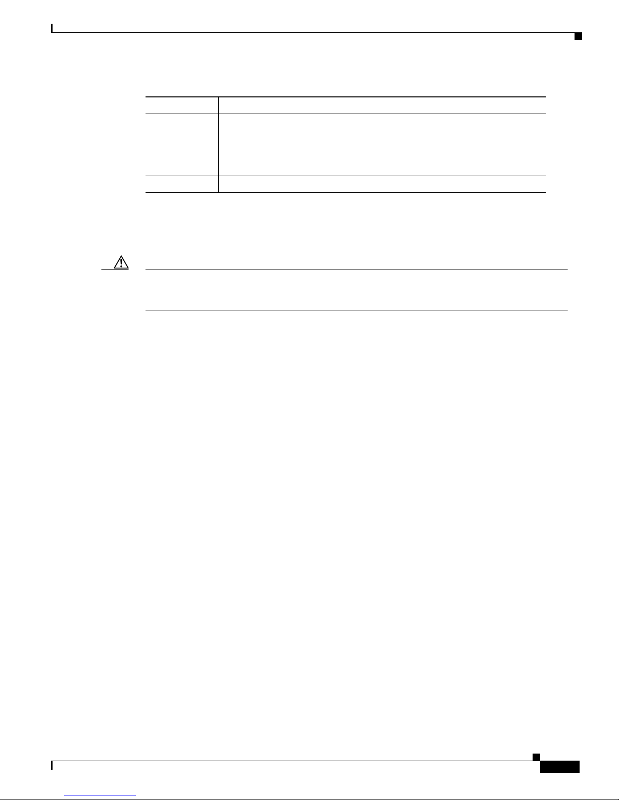
Table 1 STATUS LED Description (continued)
Color Description
Orange Indicates one of three conditions:
Off The NAM power is off.
SHUTDOWN Button
Caution Do not remove the NAM from the switch until the NAM has shut down completely and the STATUS
LED is orange. You can damage the NAM if you remove it from the switch before it completely shuts
down.
To avoid corrupting the NAM hard disk, you must correctly shut down the NAM before you remove it
from the chassis or disconnect the power. This shutdown procedure is normally initiated by commands
entered at the supervisor engine CLI prompt or the NAM CLI prompt.
If the NAM fails to respond to these commands properly, you must use the SHUTDOWN button on the
front panel to initiate the shutdown procedure.
Overview
• The NAM is running through its boot and self-test diagnostic sequence.
• The NAM is disabled.
• The NAM is in the shutdown state.
To push the button, use a small pointed object (such as a paper clip).
The shutdown procedure may require several minutes. The STATUS LED turns off when the NAM shuts
down.
Hard Drive Activity LED
The hard drive (HD) activity LED is lit when the hard drive is in use.
PCMCIA Slot
The PCMCIA slot provides access for up to two standard PCMCIA cards (now known as PC cards) and
is reserved for future use.
78-10406-05
Catalyst 6000 Family Network Analysis Module Installation and Configuration Note
5
Page 6

Safety Overview
Specifications
Table 2 describes the specifications for the NAM.
Table 2 Specifications
Specification Description
Dimensions (H x W x D) 1.18 x 15.51 x 16.34 in. (30 x 394 x 415 mm)
Weight Minimum: 3 lb (1.36 kg)
Maximum: 5 lb (2.27 kg)
Environmental conditions:
Operating temperature
Nonoperating temperature
Humidity
Safety Overview
Safety warnings appear throughout this document in procedures that may harm you if performed
incorrectly.
For additional safety information, refer to documents listed in the “Related Documentation” section on
page 73.
Warning
Warning
This warning symbol means danger. You are in a situation that could cause bodily injury.
Before you work on any equipment, be aware of the hazards involved with electrical
circuitry and be familiar with standard practices for preventing accidents. To see
translations of the warnings that appear in this publication, refer to the Regulatory
Compliance and Safety Information document that accompanied this device.
WaarschuwingDit waarschuwingssymbool betekent gevaar. U verkeert in een situatie
die lichamelijk letsel kan veroorzaken. Voordat u aan enige apparatuur gaat werken,
dient u zich bewust te zijn van de bij elektrische schakelingen betrokken risico's en
dient u op de hoogte te zijn van standaard maatregelen om ongelukken te voorkomen.
Voor vertalingen van de waarschuwingen die in deze publicatie verschijnen, kunt u het
document Regulatory Compliance and Safety Information (Informatie over naleving van
veiligheids- en andere voorschriften) raadplegen dat bij dit toestel is ingesloten.
32 to 10°F (0 to 40°C)
–40 to 167°F (–40 to 75°C)
10 to 90%, noncondensing
Warning
Catalyst 6000 Family Network Analysis Module Installation and Configuration Note
VaroitusTämä varoitusmerkki merkitsee vaaraa. Olet tilanteessa, joka voi johtaa
ruumiinvammaan. Ennen kuin työskentelet minkään laitteiston parissa, ota selvää
sähkökytkentöihin liittyvistä vaaroista ja tavanomaisista onnettomuuksien
ehkäisykeinoista. Tässä julkaisussa esiintyvien varoitusten käännökset löydät laitteen
mukana olevasta Regulatory Compliance and Safety Information -kirjasesta (määräysten
noudattaminen ja tietoa turvallisuudesta).
6
78-10406-05
Page 7
Safety Overview
Warning
Warning
Warning
AttentionCe symbole d'avertissement indique un danger. Vous vous trouvez dans une
situation pouvant causer des blessures ou des dommages corporels. Avant de travailler
sur un équipement, soyez conscient des dangers posés par les circuits électriques et
familiarisez-vous avec les procédures couramment utilisées pour éviter les accidents.
Pour prendre connaissance des traductions d’avertissements figurant dans cette
publication, consultez le document Regulatory Compliance and Safety Information
(Conformité aux règlements et consignes de sécurité) qui accompagne cet appareil.
WarnungDieses Warnsymbol bedeutet Gefahr. Sie befinden sich in einer Situation, die
zu einer Körperverletzung führen könnte. Bevor Sie mit der Arbeit an irgendeinem Gerät
beginnen, seien Sie sich der mit elektrischen Stromkreisen verbundenen Gefahren und
der Standardpraktiken zur Vermeidung von Unfällen bewußt. Übersetzungen der in
dieser Veröffentlichung enthaltenen Warnhinweise finden Sie im Dokument Regulatory
Compliance and Safety Information (Informationen zu behördlichen Vorschriften und
Sicherheit), das zusammen mit diesem Gerät geliefert wurde.
AvvertenzaQuesto simbolo di avvertenza indica un pericolo. La situazione potrebbe
causare infortuni alle persone. Prima di lavorare su qualsiasi apparecchiatura, occorre
conoscere i pericoli relativi ai circuiti elettrici ed essere al corrente delle pratiche
standard per la prevenzione di incidenti. La traduzione delle avvertenze riportate in
questa pubblicazione si trova nel documento Regulatory Compliance and Safety
Information (Conformità alle norme e informazioni sulla sicurezza) che accompagna
questo dispositivo.
Warning
Warning
AdvarselDette varselsymbolet betyr fare. Du befinner deg i en situasjon som kan føre til
personskade. Før du utfører arbeid på utstyr, må du vare oppmerksom på de
faremomentene som elektriske kretser innebærer, samt gjøre deg kjent med vanlig
praksis når det gjelder å unngå ulykker. Hvis du vil se oversettelser av deadvarslene som
finnes i denne publikasjonen, kan du se i dokumentet Regulatory Compliance and Safety
Information (Overholdelse av forskrifter og sikkerhetsinformasjon) som ble levert med
denne enheten.
AvisoEste símbolo de aviso indica perigo. Encontra-se numa situação que lhe poderá
causar danos físicos. Antes de começar a trabalhar com qualquer equipamento,
familiarize-se com os perigos relacionados com circuitos eléctricos, e com quaisquer
práticas comuns que possam prevenir possíveis acidentes. Para ver as traduções dos
avisos que constam desta publicação, consulte o documento Regulatory Compliance and
Safety Information (Informação de Segurança e Disposições Reguladoras) que
acompanha este dispositivo.
78-10406-05
Catalyst 6000 Family Network Analysis Module Installation and Configuration Note
7
Page 8

Software Requirements
Warning
Warning
Warning
¡Advertencia!Este símbolo de aviso significa peligro. Existe riesgo para su integridad
física. Antes de manipular cualquier equipo, considerar los riesgos que entraña la
corriente eléctrica y familiarizarse con los procedimientos estándar de prevención de
accidentes. Para ver una traducción de las advertencias que aparecen en esta
publicación, consultar el documento titulado Regulatory Compliance and Safety
Information (Información sobre seguridad y conformidad con las disposiciones
reglamentarias) que se acompaña con este dispositivo.
Varning!Denna varningssymbol signalerar fara. Du befinner dig i en situation som kan
leda till personskada. Innan du utför arbete på någon utrustning måste du varamedveten
om farorna med elkretsar och känna till vanligt förfarande för att förebygga skador. Se
förklaringar av de varningar som förkommer i denna publikation i dokumentet Regulatory
Compliance and Safety Information (Efterrättelse av föreskrifter och
säkerhetsinformation), vilket medföljer denna anordning.
Only trained and qualified personnel should be allowed to install, replace, or service this
equipment.
Software Requirements
Table 3 lists the NAM software versions supported by Catalyst OS and Cisco IOS software.
Table 3 NAM Software Compatibility
NAM Software Catalyst Software Cisco IOS Software
Application Image Maintenance Image
1.1(1a) 1.1(1a)m or later 5.5(1) to 6.3(1) Not applicable
1.2(1), 1.2(2) 1.2(1a)m 6.1(1d) or later 12.1(8a)EX with
Supervisor Engine 2
with an MSFC 2.
1.2(3) 1.2(1a)m 5.5(1) or later 12.1(8a)EX or later
with Supervisor Engine
2 with an MSFC 2.
12.1(11b)E or later with
a Supervisor Engine 1A
with an MSFC 2, or a
Supervisor Engine 2
with an MSFC 2.
2.1(1a) 1.2(1a)m 6.1(1d) or later Not applicable
2.1(2) 1.2(1a)m 6.1(1d) or later 12.1(11b)E or later with
a Supervisor Engine 1A
with an MSFC 2, or a
Supervisor Engine 2
with an MSFC 2.
Catalyst 6000 Family Network Analysis Module Installation and Configuration Note
8
78-10406-05
Page 9

Hardware Requirements
For Catalyst OS, any Catalyst 6000 or 6500 series switch with any supervisor module is supported using
Supervisor Engine 1, 1A, or 2. For Cisco IOS, any Catalyst 6000 or 6500 series switch with a Supervisor
Engine 1A (or Supervisor Engine 2) with an MSFC2 if it is running 12.1(11b)E. If the switch is running
the older 12.1(8a)EX, a Supervisor Engine 2 with an MSFC2 is required.
Required Tools
Note Before installing the NAM, you must install the Catalyst 6000 family switch chassis and at least one
supervisor engine. For information on installing the switch chassis, refer to the Catalyst 6000 Family
Installation Guide.
These tools are required to install the NAM in the Catalyst 6000 family switches:
• Flat-blade screwdriver
• Phillips-head screwdriver
• Wrist strap or other grounding device
Hardware Requirements
• Antistatic mat or antistatic foam
Whenever you handle the NAM, always use a wrist strap or other grounding device to prevent
electrostatic discharge (ESD).
Installing and Removing the NAM
Warning
During this procedure, wear grounding wrist straps to avoid ESD damage to the card. Do not
directly touch the backplane with your hand or any metal tool, or you could shock yourself.
All Catalyst 6000 family switches support hot swapping, which allows you to install, remove, replace,
and rearrange modules without turning off the system power. For more information on removing the
NAM from a switch, see the “Removing the NAM” section on page 15.
When the system detects that a module has been installed or removed, it automatically runs diagnostic
and discovery routines, acknowledges the presence or absence of the module, and resumes system
operation with no operator intervention.
Installing and using the NAM requires the following:
• Perform the initial installation by placing the NAM in a switch.
• Go to switch CLI, session to the NAM CLI and provide a basic configuration
• Send a data source to the NAM (Netflow data, SPANned ports, VLANs, or etherchannels)
• Configure collection types of you want to monitor (RMON, voice, application response time, and
other collection monitoring as required for your network).
• Configure alarms.
• View monitored statistics, alarms, and use packet capture or decode functionality.
78-10406-05
Catalyst 6000 Family Network Analysis Module Installation and Configuration Note
9
Page 10

Installing and Removing the NAM
This section describes how to install and verify the operation of the NAM in the Catalyst 6000 family
switches and contains the following sections:
• Slot Assignments, page 10
• Verifying the Installation, page 14
• Removing the NAM, page 15
Slot Assignments
The Catalyst 6006 and 6506 switch chassis have six slots, the Catalyst 6009 and 6509 switch chassis
have nine slots, and the Catalyst 6513 switch chassis has thirteen slots. (See Figure 2.)
Note The Catalyst 6509-NEB switch has vertical slots numbered 1 to 9 from right to left. Install the
modules with the component side facing to the right.
• Slot 1 is reserved for the supervisor engine.
• Slot 2 can contain an additional redundant supervisor engine in case the supervisor engine in slot 1
• If a redundant supervisor engine is not required, slots 2 through 6 on the 6-slot chassis, (slots 2
fails.
through 9 on the 9-slot chassis and slots 2 through 13 on the 13-slot chassis) are available for
switching modules, such as the NAM.
• Install switching-module filler plates, which are blank switching-module carriers, in the empty slots
to maintain consistent airflow through the switch chassis.
Catalyst 6000 Family Network Analysis Module Installation and Configuration Note
10
78-10406-05
Page 11
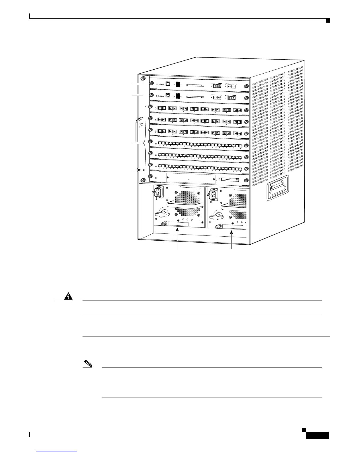
Figure 2 Slot Numbers on Catalyst 6000 Family Switches
Installing and Removing the NAM
Supervisor engine
Redundant supervisor
engine
Switching
modules
Fans
WS-X6K-SUP1
STATUS
S
1
SUPERVISOR I
WS-X6K-SUP1
STATUS
SYSTEM
2
SUPERVISOR I
W
S-X6408
STATUS
3
8 PORT G
IGABIT ETHERN
W
S-X6408
4
STATUS
8 PORT GIGABIT ETH
ERNET
W
S-X64
08
STATUS
5
8 PORT G
IGABIT ETHER
W
S
X
6
2
2
4
S
U
T
A
6
T
S
2
4
P
O
R
T
1
0
0F
X
W
S
-X
6
2
2
4
S
U
T
A
T
S
7
2
4
P
O
R
T
1
0
0
F
X
W
S
X
6
2
2
4
S
U
T
A
T
S
8
FAN
LED
2
4
P
O
R
T
1
0
0F
X
W
S
-X
6
3
80
-N
A
M
S
U
T
A
T
S
9
N
T
W
K
A
N
A
L
Y
S
IS
H
S
w
i
t
c
h
L
o
a
d
T
1
0
0
%
D
T
E
/
R MGM
SET
YSTEM
ACTIVE
D
C
PW
E
RE
C
O
N
S
O
L
E
1
%
S
w
1
0
0
%
E
D
T
E
/
ACTIV
D
C
PWR MGMT
E
RESET
C
O
N
S
O
L
E
1
%
1
2
K
ET
K
IN
L
IN
L
1
2
LINK
LINK
1
2
NET
LINK
LINK
1
2
3
4
5
LINK
LINK
LINK
LINK
LINK
1
2
3
4
5
LINK
LINK
LINK
LINK
LINK
1
2
3
4
5
LINK
LINK
LINK
LINK
LINK
D
L
P
C
M
C
I
A
i
tc
h
L
o
a
d
P
C
M
C
IA
3
4
K
K
N
I
L
IN
L
3
4
LINK
LINK
3
4
K
LINK
LIN
6
7
8
9
1
0
1
1
LINK
LINK
LINK
LINK
LINK
LINK
6
7
8
9
1
0
1
LINK
6
LINK
1
LINK
LINK
LINK
LINK
LINK
7
8
9
10
11
LINK
LINK
LINK
LINK
LINK
For Vendor Use O
nly
S
H
U
T
D
O
W
N
o
INPUT
FAN
OUTPUT
OK
OK
FAIL
P
O
R
T
1
P
O
R
T
E
J
E
C
T
LINK
E
J
E
C
T
LINK
5
K
N
I
L
5
K
IN
L
5
INK
L
1
2
1
3
1
4
1
5
1
6
LINK
LINK
LINK
LINK
LINK
1
2
1
3
1
4
1
5
1
6
LINK
LINK
LINK
LINK
LINK
12
13
14
15
16
LINK
LINK
LINK
LINK
LINK
2
LINK
P
O
R
T
1
P
O
R
T
2
LINK
6
7
K
N
I
L
6
K
IN
L
6
INK
L
1
7
1
8
LINK
1
7
1
8
LINK
17
18
LINK
S
L
O
M
D
8
K
K
IN
L
IN
L
7
8
LINK
LINK
7
8
LINK
LINK
1
9
2
0
2
1
2
2
2
3
2
LINK
1
9
LINK
19
T
1
0
4
LINK
LINK
LINK
LINK
LINK
LINK
2
0
2
1
2
2
2
3
2
4
LINK
LINK
LINK
LINK
LINK
LINK
20
21
22
23
24
LINK
P
C
M
C
IA
E
J
E
C
T
o
INPUT
FAN
OUTPUT
OK
OK
FAIL
33086
Installing the NAM
Warning
Step 1 Make sure you take the necessary precautions to prevent ESD damage.
Step 2 Choose a slot for the NAM. (Refer to “Slot Assignments” section on page 10.)
During this procedure, wear grounding wrist straps to avoid ESD damage to the card. Do not
directly touch the backplane with your hand or any metal tool, or you could shock yourself.
To install the NAM in the Catalyst 6000 family switch, follow these steps:
Note Yo u must install the supervisor engine in slot 1. You can install a redundant supervisor engine
Power supply 1
Power supply 2
in slot 2. If a redundant supervisor engine is not required, slots 2 through 6 on the 6-slot
chassis, (slots 2 through 9 on the 9-slot chassis and slots 2 through 13 on the 13-slot chassis)
are available for switching modules.
78-10406-05
Catalyst 6000 Family Network Analysis Module Installation and Configuration Note
11
Page 12
Installing and Removing the NAM
Step 3 If the desired slot is empty and is not covered by a switching-module filler plate, go to Step 5.
Otherwise, loosen the captive installation screws (with a screwdriver if necessary) that secure the
switching-module filler plate or the existing switching module in the desired slot.
Warning
Blank faceplates and cover panels serve three important functions: they prevent exposure to
hazardous voltages and currents inside the chassis; they contain electromagnetic interference
(EMI) that might disrupt other equipment; and they direct the flow of cooling air through the
chassis. Do not operate the system unless all cards, faceplates, front covers, and rear covers are
in place.
Step 4 Remove the switching-module filler plate or the existing switching module.
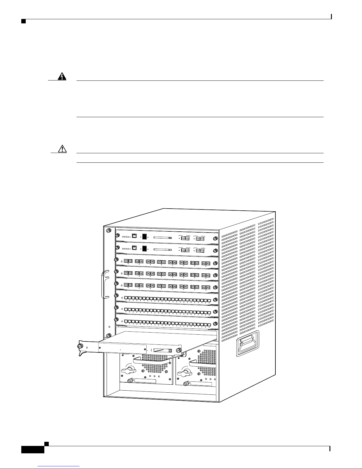
Step 5 Hold the NAM with one hand, and place your other hand under the carrier to support the module.
Caution Do not touch the printed circuit boards or connector pins.
Step 6 Place the module in the slot.
Step 7 Align the notch on the sides of the switching-module carrier with the groove in the slot. (See Figure 3.)
Figure 3 Installing Modules in the Catalyst 6000 Family Switch
WS-X6K-SUP1
STATUS
1
SUPERVISOR I
WS-X6K-SUP1
STATUS
2
SUPERVISOR I
W
S-X6408
STATUS
3
8 POR
T G
IGABIT ETHERNET
W
S-X64
08
4
STATUS
8 PORT GIGABIT ETHERNET
W
S-X6408
STATUS
5
8 PORT GIG
ABIT ETHERNET
W
S
-X
6
2
2
4
S
U
T
A
6
T
S
2
4
P
O
R
T
1
0
0
F
X
W
S
X
6
2
2
4
S
U
T
A
T
S
7
2
4
P
O
R
T
1
0
0
F
X
W
S
-X
6
2
2
4
S
U
T
A
T
S
8
2
4
P
O
R
T
1
0
0
F
X
FAN
LED
9
S
w
itc
h
L
o
a
d
1
0
0
%
D
T
E
/
SYSTEM
ACTIVE
D
C
PWR MGMT
E
RESET
C
O
N
S
O
L
E
1
%
S
w
itc
1
0
0
%
D
T
E
/
SYSTEM
ACTIVE
D
C
PWR MGMT
E
RESET
C
O
N
S
O
L
E
1
%
1
2
K
K
IN
L
IN
L
1
2
K
LIN
LINK
1
2
K
K
LIN
LIN
1
2
3
4
5
LINK
LINK
LINK
LINK
LINK
1
2
3
4
5
K
K
K
K
IN
K
IN
L
IN
L
IN
L
IN
L
L
1
2
3
4
5
K
K
K
K
IN
K
IN
L
IN
L
IN
L
IN
L
L
P
C
M
C
IA
h
L
o
a
d
P
C
M
C
IA
3
4
K
K
IN
N
L
I
L
3
4
LINK
LINK
3
4
LINK
LINK
6
7
8
9
10
11
LINK
6
K
IN
L
6
K
N
I
L
12
LINK
LINK
LINK
LINK
LINK
7
8
9
1
0
1
1
1
K
K
K
K
IN
K
IN
L
IN
L
IN
L
IN
L
L
7
8
9
10
11
12
K
K
K
N
K
I
K
IN
L
IN
L
IN
L
IN
L
L
P
O
R
T
1
P
O
R
T
E
J
E
C
T
LINK
E
J
E
C
T
LINK
5
K
IN
L
5
LINK
5
LINK
13
14
15
16
LINK
LINK
LINK
LINK
LINK
2
13
1
4
15
16
K
K
K
K
IN
K
IN
L
IN
L
IN
L
IN
L
L
13
14
15
16
K
K
K
K
IN
K
IN
N
L
I
L
IN
N
L
I
L
L
2
LINK
P
O
R
T
1
P
O
R
T
2
LINK
6
7
K
IN
L
6
LINK
6
LINK
17
18
LINK
17
18
K
IN
L
17
18
K
IN
L
8
K
K
IN
L
IN
L
7
8
LINK
LINK
7
8
LINK
LINK
19
20
21
22
23
LINK
19
K
IN
L
19
K
IN
L
24
LINK
LINK
LINK
LINK
LINK
LINK
2
0
2
1
22
23
24
K
K
K
K
IN
K
IN
L
K
IN
L
K
IN
L
IN
L
IN
L
IN
L
L
20
21
22
23
24
K
K
K
K
IN
K
IN
N
L
I
L
IN
L
IN
L
L
W
S
-X
6
3
8
0
-N
A
M
S
U
T
A
T
S
N
T
W
K
A
N
A
L
Y
S
IS
H
D
L
For Vendor Use Only
S
H
U
T
D
O
W
N
Catalyst 6000 Family Network Analysis Module Installation and Configuration Note
12
S
L
O
T
1
0
M
D
P
C
M
C
I
A
E
J
E
C
T
o
INPUT
FAN
OUTPUT
OK
OK
FAIL
o
INPUT
FAN
OUTPUT
OK
OK
FAIL
33087
78-10406-05
Page 13
Installing and Removing the NAM
Caution Always use the ejector levers when installing or removing the NAM. A module that is partially seated
in the backplane will cause the system to halt and subsequently crash.
Step 8 Keep the NAM at a 90-degree orientation to the backplane (horizontal to the floor), and carefully slide
the module into the slot until the notches on both ejector levers engage the chassis sides.
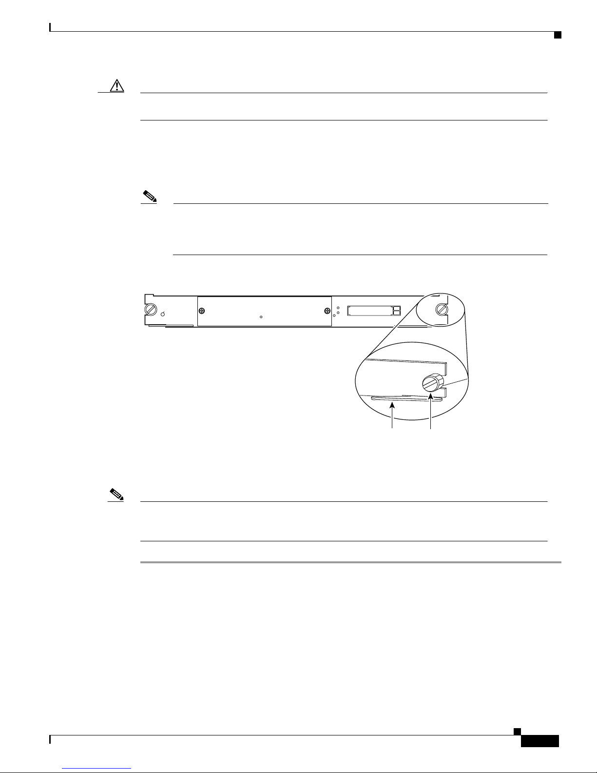
Step 9 Using the thumb and forefinger of each hand, simultaneously pivot both ejector levers forward to fully
seat the module in the backplane connector. (See Figure 4.)
Note If you perform a hot swap, the console displays the message “Module n has been inserted.”
If you are running Cisco IOS, the console displays the message “Power to Module in slot n
set on.” These messages do not appear when you are connected to the Catalyst 6000 family
switch through a Telnet session.
Figure 4 Ejector Levers and Captive Installation Screws
WS-X6380-NAM
STATUS
NTWK ANALYSIS HDL
For Vendor Use Only
SHUTDOWN
SLOT
1
0
MD
PCMCIA
Ejector lever
EJECT
33088
Captive
installation
screws
Step 10
Use a screwdriver to tighten the captive installation screws on the left and right sides of the NAM.
Note After you install or reinstall the NAM into a switch, you must log in to the NAM root account and
configure the NAM parameters before you can use the NAM for network analysis. See the “Initial
Configuration” section on page 24 for instructions on how to configure the NAM parameters.
78-10406-05
Catalyst 6000 Family Network Analysis Module Installation and Configuration Note
13
Page 14

Installing and Removing the NAM
Verifying the Installation
These sections describe how to verify the installation of the NAM.
• Cisco IOS Software, page 14
• Catalyst OS Software, page 14
Cisco IOS Software
To verify that the switch acknowledges the new NAM and has brought it online, enter the show module
command.
This example shows the output of the show module command:
Router#show mod
Mod Ports Card Type Model Serial No.
--- ----- -------------------------------------- ------------------ ---------- 2 2 Catalyst 6000 supervisor 2 (Active) WS-X6K-SUP2-2GE SAD0410050B
3 48 48 port 10/100 mb RJ-45 ethernet WS-X6248-RJ-45 SAD03080485
5 2 Network Analysis Module WS-X6380-NAM SAD05130AXB
7 2 Intrusion Detection System WS-X6381-IDS SAD05100HPT
Mod MAC addresses Hw Fw Sw Status
--- ------------------------------- ------ ------------ ------------ ------ 2 0050.3e7e.70a2 to 0050.3e7e.70a3 90.223 6.1(3) 7.1(0.9) Ok
3 00e0.b0ff.9050 to 00e0.b0ff.907f 0.702 4.2(0.24) 7.1(0.9) Ok
5 0003.32bb.dacb to 0003.32bb.dacc 1.2 4B4LZ0XA 1.2(01) Ok
7 0003.3283.cae6 to 0003.3283.cae7 1.1 4B4LZ0XA 2.5(1) Ok
Mod Sub-Module Model Serial Hw Status
--- --------------------------- --------------- --------------- ------- ------ 2 Policy Feature Card 2 WS-F6K-PFC2 SAD040801JA 0.305 Ok
2 Cat6k MSFC 2 daughterboard WS-F6K-MSFC2 SAD04450FSS 1.1 Ok
When running Cisco IOS enter the show interface GigabitEthernet slot/ [1 | 2] command while logged
in to the supervisor engine or console to verify that the switch acknowledges the new modules and has
brought them online.
Catalyst OS Software
To verify that the switch acknowledges the new NAM and has brought it online, enter the show module
or show port [mod/port] command.
This example shows the output of the show module command:
Console> (enable) show module
Mod Slot Ports Module-Type Model Sub Status
--- ---- ----- ------------------------- ------------------- --- -------1 1 2 1000BaseX Supervisor WS-X6K-SUP1A-2GE yes ok
15 1 1 Multilayer Switch Feature WS-F6K-MSFC no ok
3 3 2 Network Analysis Module WS-X6380-NAM no ok
5 5 48 10/100BaseTX Ethernet WS-X6248-RJ-45 no ok
.
.
.
Console> (enable)
Catalyst 6000 Family Network Analysis Module Installation and Configuration Note
14
78-10406-05
Page 15

Removing the NAM
This section describes how to remove the NAM from the Catalyst 6000 family switch.
Caution Do not remove the NAM from the switch until the NAM has shut down completely and the STATUS
LED is orange or off. You can damage the NAM if you remove it from the switch before it completely
shuts down.
Installing and Removing the NAM
Warning
During this procedure, wear grounding wrist straps to avoid ESD damage to the card. Do not
directly touch the backplane with your hand or any metal tool, or you could shock yourself.
To remove the NAM, follow these steps:
Step 1 Shut down the NAM by one of these methods:
• Cisco IOS software
–
From the root account on the NAM, enter the shutdown command.
–
In privileged mode from the CLI, enter the hw-mod module mod shutdown command. (When
this command is used, you will have to enter the hw-mod module mod reset command in order
to restart the NAM.)
Note When the switch is rebooted, the NAM will reboot.
–
If the NAM does not respond to any commands from the NAM prompt or the supervisor engine,
use a small, pointed object to access the SHUTDOWN button.
• Catalyst OS software
–
From the root account on the NAM, enter the shutdown command.
–
In privileged mode from the CLI, enter the set module disable mod command. (When this
command is used, you will have to enter the set module enable mod command in order to restart
the NAM.)
When you enter the set module disable mod command, the specified NAM will remain
disabled, even if the switch is rebooted, until you enter the set module enable mod command.
–
In privileged mode from the CLI, enter the set module shutdown mod command. This form of
the command will shut down only the specified NAM.
When you enter the set module shutdown command, the NAM will reboot if the switch is
rebooted.
–
In privileged mode from the CLI, enter the set module shutdown all command.
When you enter the set module shutdown all command, you will shut down every NAM
installed in the switch.
–
If the NAM does not respond to any commands from the NAM prompt or the supervisor engine,
use a small, pointed object to access the SHUTDOWN button.
Note Shutdown may require several minutes.
78-10406-05
Catalyst 6000 Family Network Analysis Module Installation and Configuration Note
15
Page 16

Configuring the NAM
Step 2 Verify that the NAM shuts down. Do not remove the NAM from the switch until the STATUS LED is
Step 3 Use a screwdriver to loosen the captive installation screws at the left and right sides of the NAM.
Step 4 Grasp the left and right ejector levers. Simultaneously, pull the left lever to the left and the right lever to
Step 5 As you pull the module out of the slot, place one hand under the carrier to support it. Avoid touching
Step 6 Carefully pull the NAM straight out of the slot, keeping one hand under the carrier to guide it. Keep the
Step 7 Place the removed module on an antistatic mat or antistatic foam.
off or orange.
the right to release the NAM from the backplane connector.
the module itself.
module at a 90-degree orientation to the backplane (horizontal to the floor).
Warning
Step 8 If the slot is to remain empty, install a module filler plate to keep dust out of the chassis and to maintain
Blank faceplates and cover panels serve three important functions: they prevent exposure to
hazardous voltages and currents inside the chassis; they contain electromagnetic interference
(EMI) that might disrupt other equipment; and they direct the flow of cooling air through the
chassis. Do not operate the system unless all cards, faceplates, front covers, and rear covers are
in place.
proper airflow through the module compartment.
Configuring the NAM
How you configuring the NAM on your switch depends on whether you are using Cisco IOS software or
the Catalyst OS software. There are also NAM configuration tasks that are common to both switch
operating systems.
The following sections describe how to configure the NAM from the CLI for each switch operating
system:
• Cisco IOS Software, page 16
• Catalyst OS Software, page 24
When you have completed configuring the software-dependent attributes for the NAM, you can
configure the software-independent attributes in this section:
• Operating System-Independent Configuration, page 31
Cisco IOS Software
These sections describe how to remove the NAM from the Catalyst 6000 family switch when using Cisco
IOS:
• Initial Configuration, page 17
• Configuring VLANs, page 19
• Using NetFlow Data Export as a Traffic Source, page 20
• Using SPAN as a Traffic Source, page 22
Catalyst 6000 Family Network Analysis Module Installation and Configuration Note
16
78-10406-05
Page 17

Initial Configuration
Before you can use the NAM for network analysis, you must log into the NAM root account and
configure the following:
• IP address
• Subnet mask
• IP broadcast address
• IP host name
• Default gateway
• Domain name
• If you are using a Domain Name Service (DNS), configure the DNS name server.
• If you are using external SNMP manager to communicate with the NAM, configure the following:
• Start the web server using the ip http server enable command.
–
SNMP MIB variables
–
Access control for the SNMP agent
–
System group settings on the NAM
Configuring the NAM
To configure these parameters for the NAM, perform these steps in privileged mode:
Step 1 Enter this command to verify that the NAM is installed and that the power is on:
Router# show module mod
Step 2 Establish a console session with the NAM by entering:
Router# session slot processor 1
Step 3 At the login prompt, type root to log in to the root account.
Step 4 At the password prompt, type root as the root password.
Note If you have not changed the password from the factory-set default, a warning message
displays. If you decide to change the password from the default, see the “Changing and
Recovering the NAM CLI Passwords” section on page 48 for more information.
Step 5 Configure the IP address and subnet mask by entering:
root@localhost# ip address ip-address subnet-mask
Step 6 Configure the IP broadcast address by entering:
root@localhost# ip broadcast broadcast-address
Step 7 Configure the IP host name used in the CLI prompt, show commands, and log messages by entering:
root@localhost# ip host name
Step 8 Configure the default gateway by entering:
root@localhost# ip gateway default-gateway
Step 9 Configure the domain name for the NAM by entering:
root@localhost# ip domain domain-name
78-10406-05
Catalyst 6000 Family Network Analysis Module Installation and Configuration Note
17
Page 18

Configuring the NAM
Step 10 Configure one or more IP addresses as DNS name servers by entering:
Step 11 Verify the NAM configuration by entering:
Step 12 Configure the SNMP syslocation MIB variable by entering:
Step 13 Set the SNMP sysContact MIB variable by entering:
Step 14 Set the SNMP sysName MIB variable by entering:
root@localhost# ip nameserver ip-address [ip-address]
root@localhost# show ip
root@localhost# snmp location location-string
Note The MIB variables in Step 13 and Step 14 must be valid DisplayString texts, each with a
maximum length of 64 characters.
root@localhost# snmp contact contact-string
root@localhost# snmp name name-string
Note You can delete the SNMP location, SNMP contact, or SNMP name by entering the respective
command without any parameters.
Step 15 Set the SNMP agent community string parameter password for read-write access by entering:
root@localhost# snmp community community-string rw
Step 16 Set the SNMP agent community string parameter password for read-only access by entering:
root@localhost# snmp community community-string ro
Note Clear the SNMP community string with the snmp delete community community-string
command.
Step 17 Verify the SNMP access controls and settings by entering:
root@localhost# show snmp
After completing this configuration, the NAM is ready to use with a network-monitoring application
such as TrafficDirector or any other IETF-compliant RMON application.
Note If you are using RTM, you need to input the community strings in RTM exactly as you enter them in
the NAM.
This example shows how to configure the NAM:
Router#session slot 8 processor 1
The default escape character is Ctrl-^, then x.
You can also type 'exit' at the remote prompt to end the session
Trying 127.0.0.81 ... Open
Catalyst 6000 Family Network Analysis Module Installation and Configuration Note
18
78-10406-05
Page 19

Cisco Network Analysis Module (WS-X6380-NAM)
login: root
Password:
Network Analysis Module (WS-X6380-NAM) Console, 2.1(1)
Copyright (C) 1999, 2000, 2001 Cisco Systems, Inc.
WARNING! Default password has not been changed!
root@localhost# ip address 172.20.52.29 255.255.255.224
root@localhost# ip broadcast 172.20.52.31
root@localhost# ip host nam1
root@localhost# ip gateway 172.69.2.132
root@localhost# ip domain cisco.com
root@localhost# ip nameserver 171.62.2.132
root@localhost# show ip
IP address: 172.20.98.167
Subnet mask: 255.255.255.192
IP Broadcast: 172.20.98.191
DNS Name: namlab-shared.cisco.com
Default Gateway: 172.20.98.129
Nameserver(s): 171.69.2.133
HTTP server: Enabled
HTTP secure server: Disabled
HTTP port: 80
HTTP secure port: 443
TACACS+ configured: Yes
Exsession: On
root@localhost#
root@localhost# snmp location “Cisco Lab, Building X, Floor 1”
Configuring the NAM
Configuring VLANs
root@localhost# snmp contact “Jane Doe, Cisco Systems, (408) 111-1111”
root@localhost# snmp name “6k-NAM - Slot 2”
root@localhost# snmp community public ro
root@localhost# snmp community private rw
root@localhost# show snmp
SNMP Agent: nam1.cisco.com 172.20.52.29
SNMPv1: Enabled
SNMPv2C: Enabled
SNMPv3: Disabled
community public read
community private write
sysDescr "Catalyst 6000 Network Management Module (WS-X6380-NAM)"
sysObjectID 1.3.6.1.4.1.9.5.1.3.1.1.2.223
sysContact "Jane Doe, Cisco Systems, (408) 111-1111"
sysName "6k-NAM - Slot 2"
sysLocation "Cisco Lab, Building X, Floor 1"
root@localhost#
You must configure a VLAN for the NAM management port using the switchport access vlan
vlan-number command.
78-10406-05
Catalyst 6000 Family Network Analysis Module Installation and Configuration Note
19
Page 20

Configuring the NAM
Using NetFlow Data Export as a Traffic Source
To use NetFlow Data Export (NDE) as a traffic source for the NAM, enable the NetFlow Monitor option
to allow the NAM to receive the NDE stream. The statistics are presented on reserved ifIndex.3000.
NDE makes traffic statistics available for analysis by an external data collector. You can use NDE to
monitor all Layer 3 switched and all routed IP unicast traffic. In a Catalyst 6000 family switch, both the
PFC and the MSFC maintain NetFlow caches that capture flow-based traffic statistics. The cache on the
PFC captures statistics for Layer 3-switched flows. The cache on the MSFC captures statistics for routed
flows.
Note For information on configuring NDE, refer to the switch software configuration guide.
To configure NDE for the Cisco IOS, follow these steps:
Step 1 Determine the current NDE configuration by entering:
Router#show running-config | include mls
mls rp nde-address 172.20.27.229
mls rp ip route-map
mls rp ip
no mls ip multicast aggregate
no mls ip multicast non-rpf cef
mls aging fast
mls flow ip full
mls flow ipx destination-source
mls nde flow include protocol tcp
mls nde sender
mls qos statistics-export interval 300
mls qos statistics-export delimiter |
Router#show running-config | include flow
mls flow ip full
mls flow ipx destination-source
mls nde flow include protocol tcp
ip route-cache flow
ip route-cache flow
ip route-cache flow
ip flow-export source Vlan2
ip flow-export destination 172.20.27.229 3000
ip flow-aggregation cache as
Step 2 Determine the configured NDE exports by entering:
Router#show mls nde
Netflow Data Export enabled
Exporting flows to 172.20.27.229 (3000)
Exporting flows from 172.20.27.221 (57675)
Version:7
Include Filter is:
protocol:TCP
Exclude Filter not configured
Total Netflow Data Export Packets are:
0 packets, 0 no packets, 0 records
Total Netflow Data Export Send Errors:
IPWRITE_NO_FIB = 0
IPWRITE_ADJ_FAILED = 0
IPWRITE_PROCESS = 0
IPWRITE_ENQUEUE_FAILED = 0
IPWRITE_IPC_FAILED = 0
Catalyst 6000 Family Network Analysis Module Installation and Configuration Note
20
78-10406-05
Page 21

IPWRITE_MTU_FAILED = 0
IPWRITE_ENCAPFIX_FAILED = 0
Router#show ip flow export
Flow export is enabled
Exporting flows to 172.20.27.229 (3000)
Exporting using source interface Vlan2
Version 1 flow records
0 flows exported in 0 udp datagrams
0 flows failed due to lack of export packet
0 export packets were sent up to process level
0 export packets were dropped due to no fib
0 export packets were dropped due to adjacency issues
0 export packets were dropped due to fragmentation failures
0 export packets were dropped due to encapsulation fixup failures
0 export packets were dropped enqueuing for the RP
0 export packets were dropped due to IPC rate limiting
Step 3 Configure NDE as follows:
Router(config)#mls nde sender
Router#configure terminal
Enter configuration commands, one per line. End with CNTL/Z.
Router(config)#mls rp nde-address 172.20.27.229
Configuring the NAM
Router(config)#mls flow ip full
Router(config)#mls nde flow include protocol tcp
Router(config)#ip flow-export destination 172.20.27.229 3000
Note The UDP port number must be set at 3000.
Router(config)#ip flow-export source vlan 2
Router(config)#ip flow-aggregation cache as
Router(config-flow-cache)#enable
Router(config)#interface GigabitEthernet8/6
Router(config-if)#ip address 1.2.3.4 255.255.255.0
Router(config-if)#ip route-cache flow
When you configure a NAM module as an NDE collector, you should use the IP address of the NAM (set
up by sessioning into the NAM module).
Step 4 Synchronize NDE-related information with the NAM by entering:
Router#hw-module module 5 sync nde-info
This command may prompt you to reset the module. Use this command whenever the NDE configuration
and the NAM configuration is completed (such as a VLAN of the NAM management port and that VLAN
interface’s IP address and other configuration information).
Note If the NAM is not being used as an NDE collector, this step is not required. This step only applies to
the NAM that has version 1.2(xx). (NAM version 1.1(xx) is not supported).
78-10406-05
Catalyst 6000 Family Network Analysis Module Installation and Configuration Note
21
Page 22

Configuring the NAM
Using SPAN as a Traffic Source
Note You can configure SPAN as a traffic source using both the CLI and the NAM Traffic Analyzer
application.
To direct SPAN traffic to the NAM for monitoring, configure port 1 on the NAM as the SPAN destination
port. You cannot use ports on the NAM module as SPAN source ports.
The NAM can analyze Ethernet VLAN traffic from Ethernet or Fast Ethernet SPAN source ports. You
can also specify an Ethernet VLAN as the SPAN source.
The NAM can analyze Ethernet traffic from Ethernet, Fast Ethernet, Gigabit Ethernet, trunk port, or Fast
EtherChannel SPAN source ports. You can also specify an Ethernet VLAN as the SPAN source.
To use the SPAN source port as a traffic source for the NAM, set port 1 on the NAM as the SPAN
destination port. You cannot set port 2 on the NAM as a SPAN source port.
Refer to the Catalyst 6000 Family IOS Software Configuration Guide at the following website for more
information on SPAN:
http://www.cisco.com/univercd/cc/td/doc/product/lan/cat6000/index.htm
For more information on configuring SPAN, refer to the switch software configuration guide.
To enable SPAN on the NAM, perform one of these tasks:
Task Command
Set the source interfaces and
VLANs for the monitor session.
Enable port 1 of the NAM as a
SPAN destination.
Router (config)# monitor session {session_number} {source
{interface type slot/port} | {vlan vlan_ID}} [, | - | rx | tx | both]
Router (config)# monitor session {session_number} {destination
{interface type slot/port} [, | - ] | {vlan vlan_ID}}
Disable the monitor session. Router (config)# no monitor session session_number
Filter the SPAN session so that
only certain VLANs are seen from
Router (config)# monitor session {session_number} {filter
{vlan_ID} [, | - ]}
switch port trunks.
Show current monitor sessions. Router # show monitor session {session_number}
This example shows how to enable SPAN on the NAM:
Router#show monitor
Session 1
--------Source Ports:
RX Only: None
TX Only: None
Both: None
Catalyst 6000 Family Network Analysis Module Installation and Configuration Note
22
78-10406-05
Page 23

Source VLANs:
RX Only: None
TX Only: None
Both: None
Destination Ports:None
Filter VLANs: None
Session 2
--------Source Ports:
RX Only: None
TX Only: None
Both: None
Source VLANs:
RX Only: None
TX Only: None
Both: None
Destination Ports:None
Filter VLANs: None
Router#conf t
Enter configuration commands, one per line. End with CNTL/Z.
Router(config)#monitor session 1 source vlan 1 both
Configuring the NAM
Note The SPAN destination for the NAM must always be port 1.
Router#
00:21:10:%SYS-5-CONFIG_I:Configured from console by console
Router#conf t
Enter configuration commands, one per line. End with CNTL/Z.
Router(config)#monitor session 1 destination interface gi 8/1
Router#show monitor
Session 1
--------Source Ports:
RX Only: None
TX Only: None
Both: None
Source VLANs:
RX Only: None
TX Only: None
Both: 1
Destination Ports:Gi8/1
Filter VLANs: None
Session 2
--------Source Ports:
RX Only: None
TX Only: None
Both: None
Source VLANs:
RX Only: None
TX Only: None
Both: None
Destination Ports:None
Filter VLANs: None
Router#
78-10406-05
Catalyst 6000 Family Network Analysis Module Installation and Configuration Note
23
Page 24

Configuring the NAM
Catalyst OS Software
These sections describe how to configure the NAM from the CLI:
• Initial Configuration, page 24
• Configuring VLANs, page 27
• Using NetFlow Data Export as a Traffic Source, page 27
• Using SPAN as a Traffic Source, page 28
• Configuring the SNMP Agent, page 29
Initial Configuration
Before you can use the NAM for network analysis, you must log into the NAM root account and
configure the following:
• IP address
• Subnet mask
• IP broadcast address
• IP host name
• Default gateway
• Domain name
• If applicable, the DNS name server.
• If using an external SNMP manager to communicate with the NAM you must configure the
following:
–
SNMP MIB variables
–
Access control for the SNMP agent
–
System group settings on the NAM
• Start the web server using the ip http server enable command.
To configure these parameters for the NAM, perform these steps in privileged mode:
Step 1 Verify that the NAM is installed and that the power is on by entering this command:
Console> show module mod
Step 2 Establish a console session with the NAM by entering this command:
Console> (enable) session mod
Step 3 At the login prompt, type root to log into the root account.
Step 4 At the password prompt, type root as the root password.
Note If you have not changed the password from the factory-set default, a warning message
displays. To change the password from the default, see the “Changing and Recovering the
NAM CLI Passwords” section on page 48 for more information.
Catalyst 6000 Family Network Analysis Module Installation and Configuration Note
24
78-10406-05
Page 25

Configuring the NAM
Step 5 Configure the IP address and subnet mask by entering this command:
root@localhost# ip address ip-address subnet-mask
Step 6 Configure the IP broadcast address by entering this command:
root@localhost# ip broadcast broadcast-address
Step 7 Configure the IP host name used in the CLI prompt, show commands, and log messages by entering
this command:
root@localhost# ip host name
Step 8 Configure the default gateway by entering this command:
root@localhost# ip gateway default-gateway
Step 9 Configure the domain name for the NAM by entering this command:
root@localhost# ip domain domain-name
Step 10 Configure one or more IP addresses as DNS name servers by entering this command:
root@localhost# ip nameserver ip-address [ip-address]
Step 11 Verify the NAM configuration by entering this command:
root@localhost# show ip
Step 12 Configure the SNMP syslocation MIB variable by entering this command:
root@localhost# snmp location location-string
Note The MIB variables in Step 13 and Step 14 must be valid DisplayString texts, each with a
maximum length of 64 characters.
Step 13 Set the SNMP sysContact MIB variable by entering this command:
root@localhost# snmp contact contact-string
Step 14 Set the SNMP sysName MIB variable by entering this command:
root@localhost# snmp name name-string
Note You can delete the SNMP location, SNMP contact, or SNMP name by entering the respective
command without any parameters.
Step 15 Set the SNMP agent community string parameter password for read-write access by entering this
command:
root@localhost# snmp community community-string rw
Step 16 Set the SNMP agent community string parameter password for read-only access by entering this
command:
root@localhost# snmp community community-string ro
Note Clear the SNMP community string with the snmp delete community community-string
command.
78-10406-05
Catalyst 6000 Family Network Analysis Module Installation and Configuration Note
25
Page 26

Configuring the NAM
Step 17 Verify the SNMP access controls and settings by entering this command:
Note If you are using TrafficDirector, you must enter the community strings in TrafficDirector exactly as
root@localhost# show snmp
After completing this configuration, you can use the NAM with a network-monitoring application, such
as TrafficDirector or any other IETF-compliant RMON application.
you enter them in the NAM.
This example shows how to configure the NAM:
Console> (enable) session 2
Trying NAM-2...
Connected to NAM-2.
Escape character is '^]'.
Network Analysis Module (WS-X6380-NAM)
login: root
Password:
Network Analysis Module (WS-X6380-NAM) Console, 2.1(1a)
Copyright (C) 1999, 2000, 2001 Cisco Systems, Inc.
WARNING! Default password has not been changed!
root@localhost# ip address 172.20.52.29 255.255.255.224
root@localhost# ip broadcast 172.20.52.31
root@localhost# ip host nam1
root@localhost# ip gateway 172.69.2.132
root@localhost# ip domain cisco.com
root@localhost# ip nameserver 171.62.2.132
root@localhost# show ip
IP address: 172.20.52.29
Subnet mask: 255.255.255.224
IP Broadcast: 172.20.52.31
DNS Name: nam1.cisco.com
Default Gateway: 172.20.52.1
Nameserver(s): 171.69.2.132
root@localhost#
root@localhost# snmp location “Cisco Lab, Building X, Floor 1”
root@localhost# snmp contact “Jane Doe, Cisco Systems, (408) 111-1111”
root@localhost# snmp name “6k-NAM - Slot 2”
root@localhost# snmp community public ro
root@localhost# snmp community private rw
root@localhost# show snmp
SNMP Agent: nam1.cisco.com 172.20.52.29
SNMPv1: Enabled
SNMPv2C: Enabled
SNMPv3: Disabled
community public read
community private write
Catalyst 6000 Family Network Analysis Module Installation and Configuration Note
26
78-10406-05
Page 27

sysDescr "Catalyst 6000 Network Management Module (WS-X6380-NAM)"
sysObjectID 1.3.6.1.4.1.9.5.1.3.1.1.2.223
sysContact "Jane Doe, Cisco Systems, (408) 111-1111"
sysName "6k-NAM - Slot 2"
sysLocation "Cisco Lab, Building X, Floor 1"
root@localhost#
Configuring VLANs
You do not need to configure a VLAN as the NAM management port because that port automatically
synchronizes to the VLAN assigned to interface sc0 on the supervisor engine.
Note You cannot set the NAM management port VLAN with the set vlan mod/port command.
Using NetFlow Data Export as a Traffic Source
To use NetFlow Data Export (NDE) as a traffic source for the NAM, you must enable the NetFlow
Monitor option to allow the NAM to receive the NDE stream. The statistics are presented on reserved
ifIndex.3000.
Configuring the NAM
Note Configuration of the Multilayer Switch Function Card (MSFC) is necessary for using the NetFlow
feature. For information on configuring NDE, refer to the Catalyst 6000 Family Software
Configuration Guide.
To enable the NetFlow Monitor option, perform these tasks:
Task Command
Step 1
Enable the NetFlow Monitor option. set snmp extendedrmon netflow [enable |
disable] mod
Step 2
Verify that the NetFlow Monitor option is
show snmp
enabled.
Step 3
Enable NDE. set mls nde enable
This example shows how to enable the NetFlow Monitor option and verify that it is enabled:
Console> (enable) set snmp extendedrmon netflow enable 2
Snmp extended RMON netflow enabled
Console> (enable) show snmp
RMON: Enabled
Extended RMON Netflow Enabled : Module 2
Traps Enabled:
None
Port Traps Enabled: None
78-10406-05
Catalyst 6000 Family Network Analysis Module Installation and Configuration Note
27
Page 28

Configuring the NAM
Community-Access Community-String
---------------- -------------------read-only public
read-write private
read-write-all secret
Trap-Rec-Address Trap-Rec-Community
---------------------------------------- -------------------<...output truncated...>
Note If a NAM is installed, you do not need to specify an external data collector with a set mls nde
collector_ip [udp_port_number] command as described in the Catalyst 6000 Family Software
Configuration Guide. Ignore messages that the host and port are not set.
Using SPAN as a Traffic Source
Note You can configure SPAN as a traffic source using both the CLI and the NAM Traffic Analyzer
application.
To direct SPAN traffic to the NAM for monitoring, you must configure port 1 on the NAM module as
the SPAN destination port.
Note You cannot use NAM ports as SPAN source ports.
The NAM can analyze Ethernet traffic from Ethernet, Fast Ethernet, Gigabit Ethernet, trunk ports, or
Fast EtherChannel SPAN source ports. You also can specify an Ethernet VLAN as the SPAN source.
You can use RSPAN traffic as a SPAN source for the NAM. Verify that the SPAN source is set to the
same VLAN ID that is used for RSPAN. The SPAN destination should be set to nam_module/1.
For more information on configuring SPAN and RSPAN, refer to the switch software configuration
guide.
To set the NAM as a SPAN destination port, perform this task in privileged mode:
Task Command
Set the NAM as a SPAN destination
port.
set span {src_mod/src_ports | src_vlans | sc0} {dest_mod/1}
[rx | tx | both] [inpkts {enable | disable}] [learning {enable |
disable}] [multicast {enable | disable}] [filter vlans...]
[create]
Note The SPAN destination for the NAM must always be port 1.
Catalyst 6000 Family Network Analysis Module Installation and Configuration Note
28
78-10406-05
Page 29

Configuring the SNMP Agent
Note If you are using the NAM Traffic Analyzer application, the information in this section is optional.
You can configure the SNMP agent through the CLI or the NAM Traffic Analyzer application. Before
you can use the NAM for SNMP support or in hybrid mode using an external SNMP source or a web
server, you must log into the NAM root account and configure the following:
• SNMP MIB variables
• Access control for the SNMP agent
• System group settings on the NAM
To configure these parameters for NAM, perform these steps in privileged mode:
Step 1 Configure the SNMP sysLocation MIB variable by entering this command:
root@localhost# snmp location location-string
Note The MIB variables you enter in Step 13 and Step 14 must be valid DisplayString texts, each with a
maximum length of 64 characters.
Configuring the NAM
Step 2 Set the SNMP sysContact MIB variable by entering this command:
root@localhost# snmp contact contact-string
Step 3 Set the SNMP sysName MIB variable by entering this command:
root@localhost# snmp name name-string
Note You can delete the SNMP location, SNMP contact, or SNMP name by entering the
appropriate command without any parameters.
Step 4 Set the SNMP agent community string parameter password for read-write access by entering this
command:
root@localhost# snmp community community-string rw
Step 5 Set the SNMP agent community string parameter password for read-only access by entering this
command:
root@localhost# snmp community community-string ro
Note Clear the SNMP community string with the snmp delete community community-string
command.
Step 6 Verify the SNMP access controls and settings by entering this command:
root@localhost# show snmp
78-10406-05
Catalyst 6000 Family Network Analysis Module Installation and Configuration Note
29
Page 30

Configuring the NAM
After completing this configuration, you can use the NAM with a network monitoring application such
as TrafficDirector, NetScout nGenius Real-Time Monitor, or any other IETF-compliant RMON
application.
Note If you are using TrafficDirector, you must enter the community strings in TrafficDirector
exactly as you enter them in the NAM.
This example shows how to configure the NAM:
Console> (enable) session 2
Trying NAM-2...
Connected to NAM-2.
Escape character is '^]'.
Network Analysis Module (WS-X6380-NAM)
login: root
Password:
Network Analysis Module (WS-X6380-NAM) Console, 2.1(1a)
Copyright (C) 1999, 2000, 2001 Cisco Systems, Inc.
WARNING! Default password has not been changed!
root@localhost# ip address 172.20.52.29 255.255.255.224
root@localhost# ip broadcast 172.20.52.31
root@localhost# ip host nam1
root@localhost# ip gateway 172.69.2.132
root@localhost# ip domain cisco.com
root@localhost# ip nameserver 171.62.2.132
root@localhost# show ip
IP address: 172.20.52.29
Subnet mask: 255.255.255.224
IP Broadcast: 172.20.52.31
DNS Name: nam1.cisco.com
Default Gateway: 172.20.52.1
Nameserver(s): 171.69.2.132
root@localhost#
root@localhost# snmp location “Cisco Lab, Building X, Floor 1”
root@localhost# snmp contact “Jane Doe, Cisco Systems, (408) 111-1111”
root@localhost# snmp name “6k-NAM - Slot 2”
root@localhost# snmp community public ro
root@localhost# snmp community private rw
root@localhost# show snmp
SNMP Agent: nam1.cisco.com 172.20.52.29
SNMPv1: Enabled
SNMPv2C: Enabled
SNMPv3: Disabled
community public read
community private write
Catalyst 6000 Family Network Analysis Module Installation and Configuration Note
30
78-10406-05
Page 31

sysDescr "Catalyst 6000 Network Management Module (WS-X6380-NAM)"
sysObjectID 1.3.6.1.4.1.9.5.1.3.1.1.2.223
sysContact "Jane Doe, Cisco Systems, (408) 111-1111"
sysName "6k-NAM - Slot 2"
sysLocation "Cisco Lab, Building X, Floor 1"
root@localhost#
Operating System-Independent Configuration
The following sections describe the NAM configurations that are independent of the switch operating
system.
Configuring Automatic RMON Collections
Use the autostart command to specify that some collections should be automatically configured on
every available data source (including all known VLANs) whenever the NAM is initialized. These
collections may also be configured explicitly through SNMP by a management station on some data
sources. Collections that are explicitly configured through SNMP take precedence over “autostart”
collections, so if both are configured, only the explicitly configured collections are started on each data
source when the NAM initializes.
If you enter the command that instructs the NAM to automatically start a collection, you must reboot the
NAM for that command to take effect.
Configuring the NAM
The NAM allows the following collection types to be started automatically:
• addressMap—addressMapTable from RMON2-MIB (RFC 2021)
If the NMS never sets the addressMapMaxDesiredEntries scalar, then the NAM uses the value -1
(for no limit).
• art—artControlTable from draft-warth-rmon2-artmib-01.txt
• etherStat—etherStatsTable from RMON-MIB (RFC 1757)
• prioStats—smonPrioStatsControlTable from SMON-MIB (RFC 2613)
• vlanStats—smonVlanStatsControlTable from SMON-MIB (RFC 2613)
For example, each dataSource (interface or VLAN) is configured with an etherStatsEntry (from
RMON-1) after you enter the autostart etherstats enable command and reboot the NAM. The
etherStatsOwner field is set to the value monitor.
The automatic start process is performed after setting up any collections that were explicitly created
through SNMP by a management station, and stored in the NVRAM in the NAM. Automatic start
collections are not configured on data sources that already have a collection of that type configured
through SNMP.
Enable the etherStat collection type by entering this command from the root account of the NAM:
root@localhost# autostart etherstat enable
Enable the addressMap collection type by entering this command from the root account of the NAM:
root@localhost# autostart addressmap enable
Enable the prioStats collection type by entering this command from the root account of the NAM:
root@localhost# autostart priostats enable
78-10406-05
Catalyst 6000 Family Network Analysis Module Installation and Configuration Note
31
Page 32

Configuring the NAM
Using the ART MIB
Note You must purchase an ART MIB license from Cisco Systems before enabling it and using the ART
Enable the vlanStats collection type by entering this command from the root account of the NAM:
root@localhost# autostart vlanstats enable
Disable the vlanStats collection type by entering this command from the root account of the NAM:
root@localhost# autostart vlanstats disable
After enabling or disabling one or more collection types, you must reboot the NAM before the
configuration takes effect.
The Application Response Time (ART) MIB is enabled and disabled globally. When it is enabled, it
measures the response time on the network at the transport layer.
MIB feature.
To enable the ART MIB, perform this task in privileged mode:
Task Command
Enable the ART MIB. rmon artmib enable
To disable the ART MIB, perform this task in privileged mode:
Task Command
Disable the ART MIB. rmon artmib disable
Configuring the HTTP or HTTP Secure Server
Before you can access the NAM through a web browser (HTTP or HTTPS), you must enable the NAM
Traffic Analyzer application from the NAM CLI. For HTTP, use the ip http server enable command.
For HTTPS, use the ip http secure server enable command. Optionally, you also can configure the
HTTP (or HTTPS) servers to run on a different TCP port from the default.
Note You can use the HTTP server or the HTTP secure server, but not both.
Note The ip http secure commands are all disabled by default, and you must first download and install the
NAM strong crypto patch from www.cisco.com before you can enable them.
Catalyst 6000 Family Network Analysis Module Installation and Configuration Note
32
78-10406-05
Page 33

Configuring the HTTP Server
To configure the HTTP server parameters for the NAM, perform these steps in privileged mode:
Step 1 Configure the HTTP port by entering this command:
root@localhost# ip http secure port 8080
The HTTP server is enabled now. You must restart the
server to change HTTP port. Continue [y/n]? y
The port number range is from 1 to 65535.
Note Web root and guest user names are different from the CLI root and guest users.
Step 2 Enable the HTTP server by entering this command:
root@localhost# ip http server enable
Enabling HTTP server...
No web users configured!
Please enter a web administrator username [admin]:admin
New password:
Confirm password
User admin added.
Successfully enabled HTTP server.
Configuring the NAM
Note If you encounter the error, “[alert] httpd:Could not determine the server’s fully qualified domain
name, using 127.0.0.1 for ServerName” reboot the NAM and the HTTP server will be enabled
automatically.
Installing a Strong Crypto Patch
The ip http secure commands are all disabled by default, and you must enable the HTTP secure server
by installing a strong crypto patch.
To install a strong crypto patch, perform these steps in the NAM CLI:
Step 1 Download the patch from www.cisco.com by entering the following command in the NAM CLI:
root@localhost# patch ftp-url
ftp-url is the FTP location and the name of the strong crypto patch.
This example shows how to install a patch:
Console># patch ftp://hostname/pub/patch_rpms/cisco-nam-stro
ng-crypto-patchK9-1.0-1.i386.rpm
Proceeding with installation. Please do not interrupt.
If installation is interrupted, please try again.
Downloading cisco-nam-strong-crypto-patchK9-1.0-1.i386.rpm. Please wait...
ftp://hostname/pub/patch_rpms/cisco-nam-strong-crypto-patchK9-1.0-1.i386.rpm (
1K)
- [########################] 1K | 112.15K/s
78-10406-05
Catalyst 6000 Family Network Analysis Module Installation and Configuration Note
33
Page 34

Configuring the NAM
Step 2 After applying the patch, the ip http secure commands are enabled, and the following messages are
Step 3 Configure the HTTP port by entering this command:
1931 bytes transferred in 0.02 sec (107.96k/sec)
Verifying cisco-nam-strong-crypto-patchK9-1.0-1.i386.rpm. Please wait...
Package cisco-nam-strong-crypto-patchK9-1.0-1.i386.rpm verified.
Applying /usr/local/nam/patch/workdir/cisco-nam-strong-crypto-patchK9-1.0-1.i386
.rpm. Please wait...
########################################### [100%]
########################################### [100%]
Patch update completed successfully.
displayed:
Console> # ip http secure port 1777
Successfully changed HTTP secure port to 1777.
root@localhost# ip http secure port 8080
The HTTP server is enabled now. You must restart the
server to change HTTP port. Continue [y/n]? y
The port number range is from 1 to 65535.
Note Web root and guest user names are different from the CLI root and guest users.
Step 4 Enable the HTTP server by entering this command:
root@localhost# ip http server enable
Enabling HTTP server...
No web users configured!
Please enter a web administrator username [admin]:admin
New password:
Confirm password
User admin added.
Successfully enabled HTTP server.
Generating Certificates
Certificates are used to validate the secure server connection. You can generate a self-signed certificate
or obtain and install a certificate from a certification authority.
Generate a self-signed certificate by entering this command:
Console> (enable)# ip http secure generate self-signed-certificate
A certificate-signing request already exists. Generating a
new self signed certificate will invalidate the existing
signing request and any certificates already generated from
the existing request. Enter y to reuse the existing
certificate-signing request or n to generate a new one.
Reuse existing certificate-signing request?[y/n] y
The HTTP server is enabled now. You must restart
to generate the certificate. Continue [y/n]? y
-----BEGIN CERTIFICATE----MIIDAzCCAmygAwIBAgIBADANBgkqhkiG9w0BAQQFADBlMQswCQYDVQQGEwJBVTET
Catalyst 6000 Family Network Analysis Module Installation and Configuration Note
34
78-10406-05
Page 35

Configuring the NAM
MBEGA1UECBMKU29tZS1TdGF0ZTEhMB8GA1UEChMYSW50ZXJuZXQgV2lkZ2l0cyBQ
dHkgTHRkMR4wHAYDVQQDExVuYW1sYWItcGlrMy5jaXNjby5jb20wHhcNMDExMDMw
MTAxMDI4WhcNMDIxMDMwMTAxMDI4WjBlMQswCQYDVQQGEwJBVTETMBEGA1UECBMK
U29tZS1TdGF0ZTEhMB8GA1UEChMYSW50ZXJuZXQgV2lkZ2l0cyBQdHkgTHRkMR4w
HAYDVQQDExVuYW1sYWItcGlrMy5jaXNjby5jb20wgZ8wDQYJKoZIhvcNAQEBBQAD
gY0AMIGJAoGBANsO1T5ayA6pvkJad413V+N/ibvND0XRyXfFycTQRzeA8F4A+etV
s0Iq0muFfiL9mDr/es9TkyfIM+T2F6+NE13DxJ53ZBbh7ndb6WOnzeHLKh9EDfSI
cy2s775lCPCjfLcMsWQLWSU7XUbi/ExDpb9e2wQQgi6QBED/YRkr73KNAgMBAAGj
gcIwgb8wHQYDVR0OBBYEFIHsyecd8AW4cvt7voCFeZMarXIqMIGPBgNVHSMEgYcw
gYSAFIHsyecd8AW4cvt7voCFeZMarXIqoWmkZzBlMQswCQYDVQQGEwJBVTETMBEG
A1UECBMKU29tZS1TdGF0ZTEhMB8GA1UEChMYSW50ZXJuZXQgV2lkZ2l0cyBQdHkg
THRkMR4wHAYDVQQDExVuYW1sYWItcGlrMy5jaXNjby5jb22CAQAwDAYDVR0TBAUw
AwEB/zANBgkqhkiG9w0BAQQFAAOBgQACDyWhULAUeSIXyt9tuUrdPfF97hrpFkKy
nj1yEU4piuc9qQtxG9yCGsofAm+CiGFg6P4qJZtBF47mq81qF+48JTYwi68CGCye
suZgw0iCPQVv4KDirHBKFc0Vr/2SMrXcJImczoV2WGcxWxsVaXwpkBKF8pcMFFYd
iOULMcvFxg==
-----END CERTIFICATE----Disabling HTTP server...
Successfully disabled HTTP server.
Enabling HTTP server...
Successfully enabled HTTP server.
To obtain a certificate from a certification authority, you need to first generate a certificate-signing
request and then submit the certificate-signing request manually to the certification authority. After
obtaining the certificate from the certification authority, install the certificate.
Installing Certificates
To install a certificate from a certification authority, follow these steps:
Step 1 Generate a certificate signing request by entering this command:
root@localhost# ip http secure generate certificate-request
A certificate-signing request already exists. Generating a
new one will invalidate the existing one and any certificates
already generated from the existing request. Do you still
want to generate a new one? [y/n] y
5244 semi-random bytes loaded
Generating RSA private key, 1024 bit long modulus
.......................................++++++
.++++++
e is 65537 (0x10001)
Using configuration from /usr/local/nam/defaults/openssl.cnf
You are about to be asked to enter information that will be incorporated
into your certificate request.
What you are about to enter is what is called a Distinguished Name or a DN.
There are quite a few fields but you can leave some blank
For some fields there will be a default value,
If you enter '.', the field will be left blank.
----Country Name (2 letter code) [AU]:IN
State or Province Name (full name) [Some-State]:Tamil Nadu
Locality Name (eg, city) []:Chennai
Organization Name (eg, company) [Internet Widgits Pty Ltd]:Cisco Systems
Organizational Unit Name (eg, section) []:
Common Name (eg, your name or your server's hostname) [hostname.cisco.com]:
Email Address []:xxx@cisco.com
-----BEGIN CERTIFICATE REQUEST----MIIBzzCCATgCAQAwgY4xCzAJBgNVBAYTAklOMRMwEQYDVQQIEwpUYW1pbCBOYWR1
MRAwDgYDVQQHEwdDaGVubmFpMRYwFAYDVQQKEw1DaXNjbyBTeXN0ZW1zMR4wHAYD
VQQDExVuYW1sYWItcGlrMy5jaXNjby5jb20xIDAeBgkqhkiG9w0BCQEWEXNla2Fy
78-10406-05
Catalyst 6000 Family Network Analysis Module Installation and Configuration Note
35
Page 36

Configuring the NAM
Step 2 Install a certificate obtained from a certification authority by entering this command:
YmNAY2lzY28uY29tMIGfMA0GCSqGSIb3DQEBAQUAA4GNADCBiQKBgQC8+SR503gS
ygkf6pnHuh0LelNf6LqJjzwFfjqjS8vpkFq/QVbwqTNDIggUfbvRAIRWEKVWhpRf
rr+II2o/Xzb0RLpV2J2p3HGgoRrKC3nArIFFiSqXniEU+g2mPqsFNcOyxHNXIxEj
iBQf80DxbmvWFOpunmOQ/pGuEysNfU/46wIDAQABoAAwDQYJKoZIhvcNAQEEBQAD
gYEAVAX89pCAcRDOqPgaBEMQCmWD+wqZPnALovr7C81OLBYTgLLqdwPqoSjSYosE
w/pFnIxWN1sJ7MC8+hjnJJLjoCwbyrEyvoiAvzpsGsnAZgWUVaUpR7jlNbf8x2A1
hAOH9KchS0TpSNy13OyhuAkv0pUcM2AJqB/93u4YvuHfNOA=
-----END CERTIFICATE REQUEST-----
root@localhost# ip http secure install certificate
The HTTP server is enabled now. You must restart the
server to install certificate. Continue [y/n]? y
Cut and paste the certificate you received from
Certificate Authority. Enter a period (.), then
press enter to indicate the end of the certificate.
-----BEGIN CERTIFICATE----MIIDAzCCAmygAwIBAgIBADANBgkqhkiG9w0BAQQFADBlMQswCQYDVQQGEwJBVTET
MBEGA1UECBMKU29tZS1TdGF0ZTEhMB8GA1UEChMYSW50ZXJuZXQgV2lkZ2l0cyBQ
dHkgTHRkMR4wHAYDVQQDExVuYW1sYWItcGlrMy5jaXNjby5jb20wHhcNMDExMDMw
MTAxMDI4WhcNMDIxMDMwMTAxMDI4WjBlMQswCQYDVQQGEwJBVTETMBEGA1UECBMK
U29tZS1TdGF0ZTEhMB8GA1UEChMYSW50ZXJuZXQgV2lkZ2l0cyBQdHkgTHRkMR4w
HAYDVQQDExVuYW1sYWItcGlrMy5jaXNjby5jb20wgZ8wDQYJKoZIhvcNAQEBBQAD
gY0AMIGJAoGBANsO1T5ayA6pvkJad413V+N/ibvND0XRyXfFycTQRzeA8F4A+etV
s0Iq0muFfiL9mDr/es9TkyfIM+T2F6+NE13DxJ53ZBbh7ndb6WOnzeHLKh9EDfSI
cy2s775lCPCjfLcMsWQLWSU7XUbi/ExDpb9e2wQQgi6QBED/YRkr73KNAgMBAAGj
gcIwgb8wHQYDVR0OBBYEFIHsyecd8AW4cvt7voCFeZMarXIqMIGPBgNVHSMEgYcw
gYSAFIHsyecd8AW4cvt7voCFeZMarXIqoWmkZzBlMQswCQYDVQQGEwJBVTETMBEG
A1UECBMKU29tZS1TdGF0ZTEhMB8GA1UEChMYSW50ZXJuZXQgV2lkZ2l0cyBQdHkg
THRkMR4wHAYDVQQDExVuYW1sYWItcGlrMy5jaXNjby5jb22CAQAwDAYDVR0TBAUw
AwEB/zANBgkqhkiG9w0BAQQFAAOBgQACDyWhULAUeSIXyt9tuUrdPfF97hrpFkKy
nj1yEU4piuc9qQtxG9yCGsofAm+CiGFg6P4qJZtBF47mq81qF+48JTYwi68CGCye
suZgw0iCPQVv4KDirHBKFc0Vr/2SMrXcJImczoV2WGcxWxsVaXwpkBKF8pcMFFYd
iOULMcvFxg==
-----END CERTIFICATE----.
Disabling HTTP server...
Successfully disabled HTTP server.
Enabling HTTP server...
Successfully enabled HTTP server.
Enabling Voice Monitoring
The NAM Traffic Analyzer application allows you to view troubleshooting data collected from any
enabled voice protocols on the NAM. Enabling voice monitoring allows you to identify potential
problems with your voice network.
Note You must purchase a separate software license to enable voice monitoring on the NAM.
Catalyst 6000 Family Network Analysis Module Installation and Configuration Note
36
78-10406-05
Page 37

Before you can use the NAM for voice monitoring, you must log into the NAM root account and perform
these steps in privileged mode:
Step 1 Display the voice monitoring configuration by entering this command:
root@localhost# show options
ART mib: Enabled
Voice monitoring: Disabled
Step 2 Enable voice monitoring and verify the configuration by entering this command:
root@localhost# voice monitoring enable
root@localhost# show options
ART mib: Enabled
Voice monitoring: Enabled
Step 3 Log into the NAM Traffic Analyzer application and click the Monitor tab to configure and display
voice monitoring.
Using a TACACS+ Server
Configuring the NAM
TACACS+ is a Cisco Systems authentication protocol that provides remote access authentication and
related services. With TACACS+, user passwords are administered in a central database instead of
individual routers, providing a scalable network security solution.
When a user logs into NAM Traffic Analyzer, TACACS+ determines if the user name and password is
valid and what access privileges the user has.
Before you can use the NAM with TACACS+, you must configure both the NAM and the TACACS+
server.
To configure the NAM for TACACS+, follow these steps:
Step 1 Start the NAM Traffic Analyzer application.
Step 2 Click the Admin tab.
Step 3 Choose Users.
Step 4 Choose TACACS+.
Step 5 Click the Enable TACACS+ Administration and Authentication box.
Step 6 Follow the instructions in the online help.
78-10406-05
Catalyst 6000 Family Network Analysis Module Installation and Configuration Note
37
Page 38

Administering the NAM
Administering the NAM
How you administer the NAM on your switch depends on whether you are using the Cisco IOS software
or the Catalyst OS software. There are also NAM administration tasks that are common to either switch
operating system.
The following sections describe how to administrate the NAM from the CLI for each switch operating
system:
• Cisco IOS Software, page 38
• Catalyst OS Software, page 46
When you have completed administrating the software-dependent attributes for the NAM, you can
configure the software-independent NAM attributes in this section:
• Operating System-Independent Administration, page 53
These sections describe how to administer the NAM:
Cisco IOS Software
This section contains the various administrative tasks you can perform on the NAM with Cisco IOS:
• Logging in to the NAM, page 38
• Changing and Recovering the NAM CLI Passwords, page 48
• Resetting the NAM, page 49
• Upgrading the NAM Software, page 49
Logging in to the NAM
The NAM has two user levels with different access privileges:
• guest—Read-only access
• root—All read and write access
Note The root account uses the # prompt; the guest account uses the > prompt.
To log in to the NAM, follow these steps:
Step 1 Log in to the Catalyst 6000 family switch using the Telnet connection or the console port connection.
Step 2 At the CLI prompt, establish a console session with the NAM using the session slot slot_number
processor processor_number command, as follows:
Router#session slot 8 processor 1
The default escape character is Ctrl-^, then x.
You can also type 'exit' at the remote prompt to end the session
Trying 127.0.0.81 ... Open
The default password is “guest.”
The default password is “root.”
Cisco Network Analysis Module (WS-X6380-NAM)
Catalyst 6000 Family Network Analysis Module Installation and Configuration Note
38
78-10406-05
Page 39

Step 3 At the NAM login prompt, type root to log in as the root user or guest to log in as a guest user.
login: root
Step 4 At the password prompt, enter the password for the account. The default password for the root account
is “root” and the default password for the guest account is “guest.”
Password:
After a successful login, the command line prompt appears as follows:
Network Analysis Module (WS-X6380-NAM) Console, 2.1(1)
Copyright (c) 1999, 2000, 2001 by cisco Systems, Inc.
WARNING! Default password has not been changed!
root@localhost#
Changing and Recovering the NAM CLI Passwords
If you have not changed the password from the factory-set default, a warning message displays when
you log in to the NAM.
Administering the NAM
You can use the web application on the local database. If the administrator is unknown, you can use the
CLI to remove the local web users from the web user database with the rmwebusers command.
Note New passwords must be at least six characters in length, and may include uppercase and lowercase
letters, numbers, and punctuation marks.
To change the password, follow these steps while you are logged in to the root account on the NAM:
Step 1 Enter this command:
root@localhost# password [username]
To change the root password, Telnet to the NAM and use the password command. The password
command without the username argument defaults to the root user.
To change the guest password, use the Telnet connection to the NAM and you must use the password
guest command to change the password.
Step 2 Enter the new password:
Changing password for user root
New UNIX password:
Step 3 Enter the new password again:
Retype new UNIX password:
passwd: all authentication tokens updated successfully
This example shows how to set the password for the root account:
root@localhost# password root
Changing password for user root
78-10406-05
Catalyst 6000 Family Network Analysis Module Installation and Configuration Note
39
Page 40

Administering the NAM
Note After this command, you must reset the NAM if the software version is 1.2(1).
Resetting the NAM
New UNIX password:
Retype new UNIX password:
passwd: all authentication tokens updated successfully
If you forget or lose the password, you can enter the clear module password command from the CLI to
restore the password for the root account to “root” and the guest account to “guest.”
To restore the NAM password to the factory-set defaults, enter this command in privileged mode:
Router# clear module pc-module mod password
If you cannot reach the NAM through the CLI or an external Telnet session, enter the hw-mod module
module_number reset command to reset and reboot the NAM. The reset process requires several
minutes.
To reset the NAM from the CLI, perform this task in privileged mode:
Task Command
Reset the NAM. hw-mod module module_number reset word
The word variable is the string for PC boot device.
This example shows how to reset the NAM, installed in slot 9, from the CLI:
Router#hw-mod mod 9 reset hdd:2
Proceed with reload of module? [confirm] y
% reset issued for module 9
Note For the boot device, you can specify hdd:1 for the application image or hdd:2 for the maintenance
image.
Router#
00:26:55:%SNMP-5-MODULETRAP:Module 9 [Down] Trap
00:26:55:SP:The PC in slot 8 is shutting down. Please wait ...
To reboot the NAM from the network analysis software, perform this task while you are logged in to the
root account on the NAM:
Task Command
Reset the NAM. reboot
This example shows how to reboot the NAM:
root@localhost#reboot
Reboot the NAM? [Y/N]:y
System reboot in progress..
Catalyst 6000 Family Network Analysis Module Installation and Configuration Note
40
78-10406-05
Page 41

Upgrading the NAM Software
You can upgrade both the application software and the maintenance software. To upgrade the application
software, see the “Upgrading the NAM Application Software” section on page 50. To upgrade the
maintenance software, see the “Upgrading the NAM Maintenance Software” section on page 51.
Upgrading the NAM Application Software
To upgrade the NAM application software, follow these steps:
Step 1 Copy the NAM application software image to a directory accessible to FTP.
Step 2 Log in to the switch through the console port or through a Telnet session.
Step 3 To upgrade the application software, the NAM must be running in the maintenance image. If the NAM
is already running in the maintenance image, go to Step 4. Otherwise, enter this command in privileged
mode:
Router#hw-mod module 9 reset hdd:2
Device BOOT variable for reset = hdd:2
Warning:Device list is not verified.
Proceed with reload of module? [confirm]
% reset issued for module 9
Router#
00:03:31:%SNMP-5-MODULETRAP:Module 9 [Down] Trap
00:03:31:SP:The PC in slot 9 is shutting down. Please wait ...
00:03:41:%SNMP-5-COLDSTART:SNMP agent on host R1 is undergoing a cold
start
00:03:46:SP:PC shutdown completed for module 9
00:03:46:%C6KPWR-SP-4-DISABLED:power to module in slot 9 set off (admin
request)
00:03:49:SP:Resetting module 9 ...
00:03:49:%C6KPWR-SP-4-ENABLED:power to module in slot 9 set on
00:05:53:%SNMP-5-MODULETRAP:Module 9 [Up] Trap
00:05:53:%DIAG-SP-6-BYPASS:Module 9:Online Diagnostics is Bypassed
00:05:53:%OIR-SP-6-INSCARD:Card inserted in slot 9, interfaces are now
online
Router#
Administering the NAM
Step 4 After the NAM is back online, establish a console session with the NAM and log in to the root account.
Router#session slot 9 proc 1
The default escape character is Ctrl-^, then x.
You can also type 'exit' at the remote prompt to end the session
Trying 127.0.0.91 ... Open
Cisco Network Analysis Module (WS-X6380-NAM)
Maintenance Partition
login:root
Password:
Network Analysis Module (WS-X6380-NAM) Console, 1.2(1a)m
Copyright (c) 1999, 2000, 2001 by cisco Systems, Inc.
Step 5 Upgrade the NAM application software by entering:
root@localhost#upgrade ftp-url
ftp-url is the FTP location and name of the NAM software image file.
78-10406-05
Catalyst 6000 Family Network Analysis Module Installation and Configuration Note
41
Page 42

Administering the NAM
Step 6 Follow the screen prompts during the upgrade.
Step 7 After completing the upgrade, log out of the NAM.
Step 8 Reset the NAM by entering:
Step 9 (Optional) Verify the initial configuration after the NAM comes back online by logging into the NAM
Note If the FTP server does not allow anonymous users, use the following syntax for the ftp-url
value: ftp://user@host/absolute-path/filename. Enter your password when prompted.
Router#hw-mod mod 9 reset
Device BOOT variable for reset =
Warning:Device list is not verified.
Proceed with reload of module? [confirm]
% reset issued for module 9
Router#
00:26:55:%SNMP-5-MODULETRAP:Module 9 [Down] Trap
00:26:55:SP:The PC in slot 8 is shutting down. Please wait ...
root account and then entering:
root@localhost#show ip
root@localhost#show snmp
This example shows how to upgrade the NAM application software:
Router#hw-mod module 9 reset hdd:2
Device BOOT variable for reset = hdd:2
Warning:Device list is not verified.
Proceed with reload of module? [confirm]
% reset issued for module 9
Router#
00:16:06:%SNMP-5-MODULETRAP:Module 9 [Down] Trap
00:16:06:SP:The PC in slot 9 is shutting down. Please wait ...
00:16:21:SP:PC shutdown completed for module 9
00:16:21:%C6KPWR-SP-4-DISABLED:power to module in slot 9 set off (admin
request)
00:16:24:SP:Resetting module 9 ...
00:16:24:%C6KPWR-SP-4-ENABLED:power to module in slot 9 set on
00:18:21:%SNMP-5-MODULETRAP:Module 9 [Up] Trap
00:18:21:%DIAG-SP-6-BYPASS:Module 9:Online Diagnostics is Bypassed
00:18:21:%OIR-SP-6-INSCARD:Card inserted in slot 9, interfaces are now
online
Router#session slot 9 proc 1
The default escape character is Ctrl-^, then x.
You can also type 'exit' at the remote prompt to end the session
Trying 127.0.0.91 ... Open
Cisco Network Analysis Module (WS-X6380-NAM)
Maintenance Partition
login:root
Password:
Catalyst 6000 Family Network Analysis Module Installation and Configuration Note
42
78-10406-05
Page 43

Network Analysis Module (WS-X6380-NAM) Console, 1.2(1a)m
Copyright (c) 1999, 2000, 2001 by cisco Systems, Inc.
root@hostname.cisco.com#
upgrade ftp://root@hostname-ultra10/tftpboot/c6nam.1-2-1.bin.gz
Password for root@hostname-ultra10:
500 'SIZE c6nam.1-2-1.bin.gz':command not understood.
ftp://root@danlee-ultra10/tftpboot/c6nam.1-2-1.bin.gz (unknown size)
- [|] 39103K
40041798 bytes transferred in 34.57 sec (1131.27k/sec)
downloaded image version 2.1(1)
Upgrade file ftp://root@danlee-ultra10/tftpboot/c6nam.1-2-1.bin.gz
is downloaded. Upgrading will wipe out the
contents of the application partition on the hard disk.
Do you want to proceed installing it [y|N]:y
Proceeding with installation. Please do not interrupt.
If installation is interrupted or fails, boot this
partition again and restart upgrade.
00:21:50:%NAM-3-NO_RESP:Module 9 is not responding
Upgrade complete. You can boot the new application partition.
root@hostname.cisco.com# exit
Administering the NAM
[Connection to 127.0.0.91 closed by foreign host]
Router#
Router#hw-mod module 9 reset
Device BOOT variable for reset =
Warning:Device list is not verified.
Proceed with reload of module? [confirm] y
% reset issued for module 9
Router#
00:24:04:%SNMP-5-MODULETRAP:Module 9 [Down] Trap
00:24:04:SP:The PC in slot 9 is shutting down. Please wait ...
00:24:18:SP:PC shutdown completed for module 9
00:24:18:%C6KPWR-SP-4-DISABLED:power to module in slot 9 set off (admin
request)
00:24:21:SP:Resetting module 9 ...
00:24:21:%C6KPWR-SP-4-ENABLED:power to module in slot 9 set on
00:26:19:%SNMP-5-MODULETRAP:Module 9 [Up] Trap
00:26:19:%DIAG-SP-6-BYPASS:Module 9:Online Diagnostics is Bypassed
00:26:19:%OIR-SP-6-INSCARD:Card inserted in slot 9, interfaces are now
online
Upgrading the NAM Maintenance Software
To upgrade the NAM maintenance software, follow these steps:
Step 1 Copy the NAM maintenance software image to a directory accessible to FTP.
Step 2 Log in to the switch through the console port or through a Telnet session.
Step 3 If the NAM is already running in the application image go to Step 5. If not, enter this command in the
privileged mode:
Router#hw-mod module 9 reset hdd:1
Device BOOT variable for reset = hdd:1
Warning:Device list is not verified.
78-10406-05
Catalyst 6000 Family Network Analysis Module Installation and Configuration Note
43
Page 44

Administering the NAM
Step 4 After the NAM is back online, establish a console session with the NAM and log in to the root account.
Step 5 Upgrade the NAM maintenance software by entering:
Proceed with reload of module? [confirm]
% reset issued for module 9
Router#
00:31:11:%SNMP-5-MODULETRAP:Module 9 [Down] Trap
00:31:11:SP:The PC in slot 9 is shutting down. Please wait ...
00:31:25:SP:PC shutdown completed for module 9
00:31:25:%C6KPWR-SP-4-DISABLED:power to module in slot 9 set off (admin
request)
00:31:28:SP:Resetting module 9 ...
00:31:28:%C6KPWR-SP-4-ENABLED:power to module in slot 9 set on
00:33:26:%SNMP-5-MODULETRAP:Module 9 [Up] Trap
00:33:26:%DIAG-SP-6-BYPASS:Module 9:Online Diagnostics is Bypassed
00:33:26:%OIR-SP-6-INSCARD:Card inserted in slot 9, interfaces are now
online
root@localhost#upgrade ftp-url
ftp-url is the FTP location and name of the NAM software image file.
Note If the FTP server does not allow anonymous users, use the following syntax for the ftp-url
value: ftp://user@host/absolute-path/filename. Enter your password when prompted.
Step 6 Follow the screen prompts during the upgrade.
Step 7 After completing the upgrade, log out of the NAM.
Step 8 Boot into the maintenance image with this command to reset the NAM maintenance software:
Router#hw-mod module 9 reset hdd:2
Device BOOT variable for reset = hdd:2
Warning:Device list is not verified.
Proceed with reload of module? [confirm]
% reset issued for module 9
Router#
00:16:06:%SNMP-5-MODULETRAP:Module 9 [Down] Trap
00:16:06:SP:The PC in slot 9 is shutting down. Please wait ...
00:16:21:SP:PC shutdown completed for module 9
00:16:21:%C6KPWR-SP-4-DISABLED:power to module in slot 9 set off (admin
request)
00:16:24:SP:Resetting module 9 ...
00:16:24:%C6KPWR-SP-4-ENABLED:power to module in slot 9 set on
00:18:21:%SNMP-5-MODULETRAP:Module 9 [Up] Trap
00:18:21:%DIAG-SP-6-BYPASS:Module 9:Online Diagnostics is Bypassed
00:18:21:%OIR-SP-6-INSCARD:Card inserted in slot 9, interfaces are now
online
Router#
Step 9 (Optional) Verify the initial configuration after the NAM comes back online by logging into the NAM
root account and enter the following command:
root@localhost# show ip
Step 10 (Optional) Reboot into the application image by entering:
Router#hw-mod module 9 reset
Catalyst 6000 Family Network Analysis Module Installation and Configuration Note
44
78-10406-05
Page 45

This example shows how to upgrade the NAM maintenance software:
Router#
Router#hw-mod module 9 reset hdd:1
Device BOOT variable for reset = hdd:1
Warning:Device list is not verified.
Proceed with reload of module? [confirm]
% reset issued for module 9
Router#
00:31:11:%SNMP-5-MODULETRAP:Module 9 [Down] Trap
00:31:11:SP:The PC in slot 9 is shutting down. Please wait ...
00:31:25:SP:PC shutdown completed for module 9
00:31:25:%C6KPWR-SP-4-DISABLED:power to module in slot 9 set off (admin
request)
00:31:28:SP:Resetting module 9 ...
00:31:28:%C6KPWR-SP-4-ENABLED:power to module in slot 9 set on
00:33:26:%SNMP-5-MODULETRAP:Module 9 [Up] Trap
00:33:26:%DIAG-SP-6-BYPASS:Module 9:Online Diagnostics is Bypassed
00:33:26:%OIR-SP-6-INSCARD:Card inserted in slot 9, interfaces are now
online
Router#
Router#session slot 9 proc 1
The default escape character is Ctrl-^, then x.
You can also type 'exit' at the remote prompt to end the session
Trying 127.0.0.91 ... Open
Administering the NAM
Cisco Network Analysis Module (WS-X6380-NAM)
login:root
Password:
Network Analysis Module (WS-X6380-NAM) Console, 2.1(1)
Copyright (c) 1999, 2000, 2001 by cisco Systems, Inc.
root@hostname.cisco.com#
< upgrade ftp://hostname:/pub/rmon/c6nam-maint.1-2-1a-m.bin.gz
ftp://hostname:/pub/rmon/c6nam-maint.1-2-1a-m.bin.gz (119506K)
- [########################] 119506K | 611.83K/s
122374624 bytes transferred in 195.33 sec (611.82k/sec)
downloaded image version 1.2(1a)m
Upgrade file ftp://hostname:/pub/rmon/c6nam-maint.1-2-1a-m.bin.gz
is downloaded. Upgrading will wipe out the
contents of the maintenance partition on the hard disk.
Do you want to proceed installing it [y|N]:y
Proceeding with installation. Please do not interrupt.
If installation is interrupted or fails, boot this
partition again and restart upgrade.
Upgrade complete. You can boot the new maintenance partition.
root@hostname.cisco.com# exit
Router#
Router#hw-mod module 9 reset hdd:2
Device BOOT variable for reset = hdd:2
Warning:Device list is not verified.
Proceed with reload of module? [confirm]
% reset issued for module 9
Router#
02:27:19:%SNMP-5-MODULETRAP:Module 9 [Down] Trap
78-10406-05
Catalyst 6000 Family Network Analysis Module Installation and Configuration Note
45
Page 46

Administering the NAM
02:27:19:SP:The PC in slot 9 is shutting down. Please wait ...
02:27:36:SP:PC shutdown completed for module 9
02:27:36:%C6KPWR-SP-4-DISABLED:power to module in slot 9 set off (admin
request)
02:27:39:SP:Resetting module 9 ...
02:27:39:%C6KPWR-SP-4-ENABLED:power to module in slot 9 set on
02:29:37:%SNMP-5-MODULETRAP:Module 9 [Up] Trap
02:29:37:%DIAG-SP-6-BYPASS:Module 9:Online Diagnostics is Bypassed
02:29:37:%OIR-SP-6-INSCARD:Card inserted in slot 9, interfaces are now
online
Router#
Catalyst OS Software
This section contains the various administrative tasks you can perform on the NAM using the
Catalyst OS software:
• Logging into the NAM, page 47
• Changing and Recovering the NAM CLI Passwords, page 48
• Resetting the NAM, page 49
• Upgrading the NAM Software, page 49
You can administer the NAM by using the NAM Traffic Analyzer application. Refer to the User Guide
for the Catalyst 6000 Network Analysis Module NAM Traffic Analyzer.
You can perform these administrative tasks on the NAM:
• Add and remove NAM users and change passwords using either the CLI or the NAM Traffic
Analyzer application.
• Recover passwords as superuser (but not change passwords).
• Change local and remote (TACACS+ server) users and passwords by using the NAM Traffic
Analyzer application. Refer to the NAM Traffic Analyzer application online help topic “User and
System Administration” for information about user and password administration.
Catalyst 6000 Family Network Analysis Module Installation and Configuration Note
46
78-10406-05
Page 47

Administering the NAM
• Table 4 describes the user administration tasks you can perform using the CLI and NAM Traffic
Analyzer application.
Table 4 NAM User Administration
User Interface Add Users Remove Users Set Password Recover Password
CLI No Yes. Use the rmwebusers
command to remove all
webusers from the local
Use the
password
command.
database.
Traffic Analyzer Add the first user with the CLI when starting the web server. Add all subsequent users
through the web GUI for the local database or through TACACS+ if the TACACS+
server is used.
Traffic Analyzer
Yes Yes Yes Contact the NAM
local database
Traffic Analyzer
Yes Yes Yes U s e a TAC AC S+ se rv e r, o r
TAC ACS +
Switch CLI.
administrator to reset
through the GUI.
From the NAM CLI, use
the rmwebusers
command.
use the ip http tacacs+
disable command.
Logging into the NAM
There are two levels of access on the NAM, each with different privileges:
• Guest—Read-only CLI access (default password is guest)
• Root—Full read-write access (default password is root)
Note The root account uses the # prompt; the guest account uses the > prompt.
To log into the NAM, follow these steps:
Step 1 Log into the Catalyst 6000 family switch using the Telnet connection or the console port connection.
Note To allow remote Telnet sessions, use the exsession on command.
Step 2 Establish a console session with the NAM at the CLI prompt, using the session mod command:
Console> (enable) session 2
Trying NAM-2...
Connected to NAM-2.
Escape character is '^]'.
Network Analysis Module (WS-X6380-NAM)
Step 3 To log into the NAM, type root to log in as the root user or guest to log in as a guest user at the login
prompt.
login: root
78-10406-05
Catalyst 6000 Family Network Analysis Module Installation and Configuration Note
47
Page 48

Administering the NAM
Step 4 At the password prompt, enter the password for the account. The default password for the root account
is “root,” and the default password for the guest account is “guest.”
Password:
After a successful login, the command-line prompt appears as follows:
Network Analysis Module (WS-X6380-NAM) Console, 2.1(1a)
Copyright (C) 1999, 2000, 2001 Cisco Systems, Inc.
WARNING! Default password has not been changed!
root@localhost#
Changing and Recovering the NAM CLI Passwords
You can use these methods to change and recover passwords:
• Use a Telnet connection to the NAM and CLI.
You can configure, change, and recover root and guest passwords:
–
To change the password, use a Telnet connection to the NAM, then use the password command
to change the password.
–
To recover the password, use the Telnet connection to the supervisor engine, then use the clear
module password module command.
• Use NAM Traffic Analyzer n on the local database.
You create the initial NAM Traffic Analyzer application user with the CLI. After starting NAM
Traffic Analyzer, you can establish and edit additional user passwords. You use NAM Traffic
Analyzer or the TACACS+ server to change passwords as follows:
–
As the NAM Traffic Analyzer application administrator, you can reset passwords.
–
If the administrator is unknown, you can use the CLI to remove the local web user database from
the web database with the rmwebusers command.
• Use the instructions in the TACACS+ server documentation.
If you have not changed the password from the factory-set default password, a warning message appears
when you log into the NAM.
Note New passwords must be at least six characters in length, and may include uppercase and lowercase
letters, numbers, and punctuation marks.
To change a password, follow these steps while logged into the NAM as root:
Step 1 Enter this command:
root@localhost# password [username]
Step 2 Enter the new password:
Changing password for user root
New UNIX password:
Catalyst 6000 Family Network Analysis Module Installation and Configuration Note
48
78-10406-05
Page 49

Step 3 Enter the new password again:
Resetting the NAM
Administering the NAM
Retype new UNIX password:
passwd: all authentication tokens updated successfully
This example shows how to set the password for the root account:
root@localhost# password root
Changing password for user root
New UNIX password:
Retype new UNIX password:
passwd: all authentication tokens updated successfully
If you forget or lose the password, you can enter the clear module password command from the CLI to
restore the password for the root account to root and the guest account to guest.
To restore the NAM password to the factory-set defaults, enter this command in privileged mode:
Console> (enable) clear module password mod
If you cannot reach the NAM through the CLI or an external Telnet session, enter the reset command to
reset and reboot the NAM. The reset process requires several minutes.
To reset the NAM from the CLI, perform this task in privileged mode:
Task Command
Reset the NAM. reset NAM_mod
This example shows how to reset the NAM, installed in slot 2, from the CLI:
Console> (enable) reset 2
Module 2 shut down in progress, please don't remove module until shutdown completed
Resetting module 2....
2000 Feb 15 15:39:42 %SYS-5-MOD_OK:Module 2 is online
Console> (enable)
To reboot the NAM, perform this task while you are logged into the root account on the NAM:
Task Command
Reset the NAM. reboot
This example shows how to reboot the NAM:
root@localhost# reboot
Reboot the NAM? [Y/N]:y
System reboot in progress..
Upgrading the NAM Software
You can upgrade both the application software and the maintenance software. To upgrade the application
software, see the “Upgrading the NAM Application Software” section on page 50. To upgrade the
maintenance software, see the “Upgrading the NAM Maintenance Software” section on page 51.
78-10406-05
Catalyst 6000 Family Network Analysis Module Installation and Configuration Note
49
Page 50

Administering the NAM
Upgrading the NAM Application Software
To upgrade the NAM application software, follow these steps:
Step 1 Copy the NAM application software image to a directory accessible to FTP.
Step 2 Log into the switch through the console port or through a Telnet session.
Step 3 To upgrade the application software, the NAM must be running in the maintenance image. If the NAM
is already running in the maintenance image, go to Step 4. Otherwise, enter this command in privileged
mode:
Console> (enable) reset mod hdd:2
Step 4 After the NAM is back online, establish a console session with the NAM and log into the root account.
Step 5 Upgrade the NAM application software by entering this command:
root@localhost# upgrade ftp-url
ftp-url is the FTP location and the name of the NAM software image file.
Note If the FTP server does not allow anonymous users, use the following syntax for the ftp-url
value: ftp://user@host/absolute-path/filename. Enter your password when prompted.
Step 6 Follow the screen prompts during the upgrade.
Step 7 After completing the upgrade, log out of the NAM.
Step 8 Reset the NAM by entering this command:
Console> (enable) reset mod
Step 9 (Optional) Verify the initial configuration after the NAM comes back online by logging into the NAM
root account and entering the following commands:
root@localhost# show ip
root@localhost# show snmp
This example shows how to upgrade the NAM application software:
Console> (enable) reset 3 hdd:2
This command will reset module 3.
Unsaved configuration on module 3 will be lost
Do you want to continue (y/n) [n]? y
Module 3 shut down in progress, please don't remove module until shutdown completed.
Console> (enable) 2001 Apr 19 14:33:31 %SYS-5-MOD_RESET:Module 3 reset from Software
2001 Apr 19 14:35:27 %SYS-5-MOD_OK:Module 3 is online
Console> (enable) session 3
Trying NAM-3...
Connected to NAM-3.
Escape character is '^]'.
Cisco Network Analysis Module (WS-X6380-NAM)
Maintenance Partition
login: root
Password:
Catalyst 6000 Family Network Analysis Module Installation and Configuration Note
50
78-10406-05
Page 51

Administering the NAM
Network Analysis Module (WS-X6380-NAM) Console, 2.1(1a)m
Copyright (C) 1999, 2000, 2001 Cisco Systems, Inc.
WARNING! Default password has not been changed!
root@nam5.cisco.com# upgrade ftp://hostname@172.20.52.3/tftpboot/c6nam.1-2-1.bin.gz
Password for hostname@172.20.52.3:
500 'SIZE c6nam.1-1-0-20.gz': command not understood.
ftp://hostname@172.20.52.3/tftpboot/c6nam.1-2-1.bin.gz (unknown size)
- [-] 39103K
40041798 bytes transferred in 48.16 sec (811.93k/sec)
Upgrade file ftp://hostname@172.20.52.3/tftpboot/c6nam.1-2-1.bin.gz
is downloaded. Upgrading will wipe out the
contents of the application partition on the hard disk.
Do you want to proceed installing it [Y/N]: y
Proceeding with installation. Please do not interrupt.
If installation is interrupted or fails, boot the maintenance
partition again and restart upgrade.
/usr/local/nam/bin/netinstall /dev/hda1 -inf=/tmp/upgrade.bin
Upgrade complete. You can boot the new application partition.
root@nam5.cisco.com# exit
Console> (enable) reset 3
Module 3 shut down in progress, please don't remove module until shutdown completed.
2000 May 25 09:30:59 %SYS-5-MOD_RESET:Module 3 reset from Software
2000 May 25 09:32:56 %SYS-5-MOD_OK:Module 3 is online
Console> (enable)
Upgrading the NAM Maintenance Software
To upgrade the NAM maintenance software, follow these steps:
Step 1 Copy the NAM maintenance software image to a directory that is accessible to FTP.
Step 2 Log into the switch through the console port or through a Telnet session.
Step 3 To upgrade the maintenance software, the NAM must be running in the application image. If the NAM
is already running in the application image, go to Step 4. Otherwise, enter this command in privileged
mode:
Console> (enable) reset mod hdd:1
Step 4 After the NAM is back online, establish a console session with the NAM and log into the root account.
Step 5 Upgrade the NAM maintenance software by entering this command:
root@localhost# upgrade ftp-url
ftp-url is the FTP location and the name of the NAM software image file.
Note If the FTP server does not allow anonymous users, use the following syntax for the ftp-url
value: ftp://user@host/absolute-path/filename. Enter your password when prompted.
Step 6 Follow the screen prompts during the upgrade.
Step 7 After completing the upgrade, log out of the NAM.
78-10406-05
Catalyst 6000 Family Network Analysis Module Installation and Configuration Note
51
Page 52

Administering the NAM
Step 8 Boot into the maintenance image with this command to reset the NAM maintenance software:
Step 9 (Optional) Verify the initial configuration after the NAM comes back online by logging into the NAM
Step 10 (Optional) Reboot into the application image by entering this command:
Console> (enable) reset mod hdd:2
root account, and enter the following commands:
root@localhost# show ip
root@localhost# show snmp
Console> (enable) reset mod hdd:1
This example shows how to upgrade the NAM maintenance software:
Console> (enable) reset 3 hdd:1
Module 3 shut down in progress, please don't remove module until shutdown completed.
2000 May 25 09:07:46 %SYS-5-MOD_RESET:Module 3 reset from Software
2000 May 25 09:09:38 %SYS-5-MOD_OK:Module 3 is online
Console> (enable) session 3
Trying NAM-3...
Connected to NAM-3.
Escape character is '^]'.
Cisco Network Analysis Module (WS-X6380-NAM)
login: root
Password:
Network Analysis Module (WS-X6380-NAM) Console, 2.1(1a)
Copyright (C) 1999, 2000, 2001 Cisco Systems, Inc.
WARNING! Default password has not been changed!
root@nam5.cisco.com# upgrade
ftp://hostname/pub/rmon/c6nam-maint.1-2-1a-m.bin.gz
ftp://hostname/pub/rmon/c6nam-maint.1-2-1a-m.bin.gz (119506K)
- [########################] 119506K | 755.54K/s
122374624 bytes transferred in 158.17 sec (755.54k/sec)
downloaded image version 1.2(1a)m
Upgrade file ftp://hostname/pub/rmon/c6nam-maint.1-2-1a-m.bin.gz
is downloaded. Upgrading will wipe out the
contents of the maintenance partition on the hard disk.
Do you want to proceed installing it [y|N]:y
Proceeding with installation. Please do not interrupt.
If installation is interrupted or fails, boot this
partition again and restart upgrade.
Upgrade complete. You can boot the new maintenance partition.
root@nam5.cisco.com# exit
Catalyst 6000 Family Network Analysis Module Installation and Configuration Note
52
78-10406-05
Page 53

Operating System-Independent Administration
The following sections describe NAM administration that is independent of the switch operating system.
Adding NAM Patch Software
To install a patch on the NAM, follow these steps:
Step 1 Log into the switch through the console port or through a Telnet session.
Step 2 To add the patch software, the NAM must be running in the application image. If the NAM is already
running in the application image, go to Step 4. Otherwise, if the NAM is in the maintenance image,
enter this command in privileged mode:
For Cisco IOS software enter:
root@localhost# hw-mod module module_number
root@localhost# reset mod hdd:2
For Catalyst OS software enter:
Console> (enable) reset mod hdd:1
Administering the NAM
Step 3 After the NAM is back online, establish a console session with the NAM, and then log into the root
account.
Step 4 Install the patch software to the NAM software by entering this command:
root@localhost# patch ftp-url
ftp-url is the FTP location and the name of the NAM patch software image file.
Note If the FTP server does not allow anonymous users, use the following syntax for the ftp-url
value: ftp://user@host/absolute-path/filename. Enter your password when prompted.
Step 5 Follow the screen prompts during the patch application process.
Step 6 Enter the following command after you apply the patch and set the port.
root@localhost# ip heep secure server enable
Step 7 (Optional) Verify the initial configuration after the NAM comes back online by logging into the NAM
root account and then entering these commands:
root@localhost# show ip
root@localhost# show patches
This Catalyst OS software example shows how to apply patch software:
Console> (enable) reset 3 hdd:1
Module 3 shut down in progress, please don't remove module until shutdown completed.
2000 May 25 09:07:46 %SYS-5-MOD_RESET:Module 3 reset from Software
2000 May 25 09:09:38 %SYS-5-MOD_OK:Module 3 is online
Console> (enable) session 3
Trying NAM-3...
Connected to NAM-3.
Escape character is '^]'.
78-10406-05
Catalyst 6000 Family Network Analysis Module Installation and Configuration Note
53
Page 54

Administering the NAM
Cisco Network Analysis Module (WS-X6380-NAM)
login: root
Password:
Network Analysis Module (WS-X6380-NAM) Console, 2.1(1a)
Copyright (C) 1999, 2000, 2001 Cisco Systems, Inc.
WARNING! Default password has not been changed!
root@nam5.cisco.com# patch
ftp://hostname/pub/patch_rpms/cisco-nam-system-patch-1.0-1.i386.rpm
Proceeding with installation. Please do not interrupt.
If installation is interrupted, please try again.
Downloading cisco-nam-system-patch-1.0-1.i386.rpm. Please wait...
ftp://hostname/pub/patch_rpms/cisco-nam-system-patch-1.0-1.i386.rpm
(4K)
- [########################] 4K |
1047.61K/s
4114 bytes transferred in 0.00 sec (970.67k/sec)
Verifying cisco-nam-system-patch-1.0-1.i386.rpm. Please wait...
Package cisco-nam-system-patch-1.0-1.i386.rpm verified.
Applying cisco-nam-system-patch-1.0-1.i386.rpm, please wait...
########################################### [100%]
########################################### [100%]
Downloading zsh-3.0.8-8.i386.rpm, please wait...
ftp://hostname/pub/patch_rpms/zsh-3.0.8-8.i386.rpm (492K)
- [########################] 492K |
810.37K/s
503944 bytes transferred in 0.61 sec (809.93k/sec)
Verifying zsh-3.0.8-8.i386.rpm, please wait...
Package /usr/local/nam/patch/workdir/zsh-3.0.8-8.i386.rpm verified.
Applying zsh-3.0.8-8.i386.rpm, please wait...
########################################### [100%]
########################################### [100%]
Downloading nam-system-dummy-1.0-1.i386.rpm, please wait...
ftp://hostname/pub/patch_rpms/nam-system-dummy-1.0-1.i386.rpm (1K)
- [########################] 1K |
1025.45K/s
1574 bytes transferred in 0.00 sec (874.37k/sec)
Verifying nam-system-dummy-1.0-1.i386.rpm, please wait...
Package /usr/local/nam/patch/workdir/nam-system-dummy-1.0-1.i386.rpm
verified.
Applying nam-system-dummy-1.0-1.i386.rpm, please wait...
########################################### [100%]
########################################### [100%]
Restoring data
This may take several minutes, please wait...
Done.
Patch update completed successfully.
root@nam5.cisco.com# exit
Catalyst 6000 Family Network Analysis Module Installation and Configuration Note
54
78-10406-05
Page 55

Administering the NAM
Additional NAM Software Administrative Commands
The NAM supports these additional administrative commands:
Command Description
config clear Clears the NVRAM configuration to the factory-set default condition,
including:
• Deleting all RMON control tables.
• Deleting all RMON1 and RMON2 filters.
• Returning the RMON configuration file to the default configuration.
No IP host configuration data is deleted.
You must reset the NAM after entering the config clear command for the
change to take effect.
This command can be used by the root account only.
coredump ftp://host/absolute-path Sends a core file to an anonymous FTP server after the RMON agent crashes.
You should always copy and save this information to a file before calling the
Cisco Technical Assistance Center (TAC). The TAC needs this information to
analyze and troubleshoot the NAM. Only one core dump file is maintained. A
newly created core dump file overwrites an existing core dump file. This
command can be used only by the root account.
Note If the FTP server does not allow anonymous users, use the following
syntax: coredump ftp://user:password@host/absolute-path.
exsession [on | off] Controls whether external Telnet sessions are accepted by the NAM from
outside the switch. The default is set to off. If the exsession command is set to
off, you can only Telnet to the NAM from the supervisor engine on the switch.
If the exsession command is set to on, new Telnet requests from any valid IP
address are accepted. This command will not drop any open sessions. This
command can be used by the root account only.
help [command] Displays a list of top-level commands or additional information for an
individual command.
ip address ip-address subnet-mask Specifies the IP address and subnet for a node on the network.
ip broadcast broadcast-address Specifies the IP broadcast address for a node on the network.
ip gateway default-gateway Specifies the default IP gateway.
ip hosts add ip address host_name [alias 1]
[alias 2]
ip hosts add
ftp://user:passwd@host/full-path/filename
ip hosts delete Deletes a host entry from the hosts file.
ip hosts delete
ftp://user:passwd@host/full-path/filename
ip nameserver ip-addr ip-addr ip-addr Specifies the IP name server used to resolve network names into network
nslookup hostname [server] Allows name server queries for information about a host. If the optional server
Adds a host entry to the hosts file.
Adds the host entries from the remote file to the hosts file.
Deletes the host entries from the remote file in the hosts file.
addresses.
is not specified, the NAM DNS servers are used.
78-10406-05
Catalyst 6000 Family Network Analysis Module Installation and Configuration Note
55
Page 56

Administering the NAM
Command Description
patch
ftp://user:passwd@host/full-path/filename
ping [-nv] [-c count] [-i wait] [-p pattern] [-s
packetsize] hostname | IP address
show autostart Enables reporting for statistics, address mappings, VLANs, and MIBs.
show bios Displays system information about the BIOS and module (including NAM
show certificate Displays certificates you have installed for secure servers.
show certificate-request Displays encrypted certificate request for secure servers.
show cpu Displays current processor load on the NAM CPU for all combined functions.
show date Displays current time-of-day information maintained by the NAM. This
show hosts Displays the hosts file.
show ip Displays current IP configuration including the HTTP server, secure server,
show memory Displays system memory statistics. Memory sizes are rounded to the nearest
show options Displays ART MIB and voice monitoring configuration status.
show patches Displays installed software patches.
show snmp Displays the SNMP configuration.
show tech-support Displays system information that the Cisco TAC might need for
snmp community community-string {ro | rw} Sets the SNMP community string value.
Applies a patch to the application software from the specified location.
Sends ICMP echo-request packets to another node on the network. To
configure ping, you can also use the command without arguments.
The following options are supported:
-n—Shows network addresses as numbers.
-v—Provides verbose output.
-c count—the Stops after sending count ECHO_REQUEST packets.
-i wait—Waits seconds between sending each packet.
-p pattern—Up to 16 pad bytes can be used to fill out packets you send.
-s packetsize—The 8 bytes of ICMP header data.
serial number) that the Cisco TAC might need for troubleshooting. Copy and
save the information to a file before calling TAC. This command can be used
by both root and guest accounts.
This command can be used by both root and guest accounts.
command can be used by both root and guest accounts.
port, secure port, and TACACS+ information.
MB. This command can be used by both root and guest accounts.
troubleshooting. Copy and save the information to a file before calling TAC.
This command can be used by the root account only.
Catalyst 6000 Family Network Analysis Module Installation and Configuration Note
56
78-10406-05
Page 57

Command Description
traceroute [-Inv] [-f first_ttl] [-m max_ttl]
[-p port] [-s src_addr] [-t tos] [-w waittime]
destination host name | IP address
[packetlen]
upgrade
ftp://user:passwd@host/full-path/filename
The following options are supported:
-I—Uses ICMP ECHO instead of UDP datagrams.
-n—Prints hop addresses numerically.
-v—Provides verbose output.
-f first_ttl—Sets the initial time-to-live used in the first outgoing packet.
-m max_ttl—Sets the maximum time-to-live (max number of hops) used.
-p port—Sets the base UDP port number used in probes.
-s src_addr—Forces the source address to be something other than the IP
address of the interface the packet is sent on.
-t tos—Sets the type-of-service in packets to the following value.
-w waittim—Sets the time (in seconds) to wait for a response to a probe.
Upgrades the maintenance software from the specified location.
Administering the NAM
The NAM also supports CLI commands for the supervisor engine, which are described in more detail in
the Catalyst 6000 Family Command Reference publication.
Cisco IOS Commands
The NAM also supports these CLI commands, which are described in more detail in the Catalyst 6000
Family IOS Command Reference publication. These commands are grouped according to mode. These
sections describe the Cisco IOS commands that interact with the NAM:
• Exec Commands, page 57
• Configuration Commands, page 58
Exec Commands
The following commands are all performed in exec mode:
Command Description
Displays installed modules, versions, and states.
show module
reload Reloads the entire switch.
show running-config Displays the configuration that is currently running.
show startup-config Displays the saved configuration.
hw-module module slot_number reset Resets the module into the application image by default.
hw-module module slot_number reset hdd:2 Resets the module into the maintenance image.
hw-module module slot_number shutdown Resets the module into the maintenance image.
show interfaces Gigabit slot_number/port_number Displays status of the interface.
show interfaces switchport module slot_number Displays current switch settings for the interfaces.
Note This command does not show the signature level.
78-10406-05
Catalyst 6000 Family Network Analysis Module Installation and Configuration Note
57
Page 58

Administering the NAM
Command Description
show interface trunk module slot_number Displays current trunk settings for the interfaces.
clock set time date Sets the current time and date.
clock update-calendar Updates the calendar time to the clock time.
clock read-calendar Updates clock time to the calendar time.
Configuration Commands
The following commands are all performed in either global configuration mode or the interface
configuration mode:
• Global Configuration Mode, page 58
• Interface Configuration Mode, page 58
Global Configuration Mode
The following commands are all performed in global configuration mode:
Command Description
power enable module slot_number Turns the power on for the NAM if it is not already on.
no power enable module slot_number Shuts down the NAM and removes power.
clock timezone zone offset Sets the timezone for the switch or NAM.
clock summer-time zone recurring Sets the switch to use summertime settings.
clock calendar valid Sets the current calendar time as the switch time on startup.
interface GigabitEthernet slot number/port number Begins configuration for each NAM port.
monitor session session {source {interface interface
interface-number | {vlan vlan-id}} [ , | - | rx| tx | both]
monitor session session {destination {interface interface
interface-number} [ , | -] {vlan vlan-id}}
Sets the sources for a SPAN session.
Sets the destination for a SPAN session.
Interface Configuration Mode
The following commands are configuration commands performed in interface configuration mode:
Command Description
switchport Sets interface as a switchport.
switchport trunk encapsulation dot1q Sets dot1q as the encapsulation type.
switchport trunk native vlan vlan Sets native VLAN for the trunk port.
switchport trunk allowed vlan vlans Sets allowed VLANs for a trunk.
switchport mode trunk Sets the interface as a trunk port.
switchport capture Sets the interface as a capture port.
switchport access vlan vlan Sets the access VLAN for the interface.
switchport mode access Sets the interface as an access port.
Catalyst 6000 Family Network Analysis Module Installation and Configuration Note
58
78-10406-05
Page 59

Unsupported Supervisor Engine CLI Commands
These CLI commands are not supported by the NAM:
• set port broadcast
• set port channel
• set port cops
• set port disable
• set port enable
• set port flowcontrol
• set port gmrp
• set port gvrp
• set port host
• set port inlinepower
• set port jumbo
• set port membership
Troubleshooting the NAM
• set port negotiation
• set port protocol
• set port qos
• set port rsvp
• set port security
• set port speed
• set port trap
• set protocolfilter
• set rgmp
• set rspan
• set snmp
• set spantree
• set trunk
• set udld
• set vlan
• set vtp
Troubleshooting the NAM
This section provides troubleshooting information for the NAM.
Note Additional troubleshooting help is available to NAM Traffic Analyzer application users in the online
help “Troubleshooting” section.
78-10406-05
Catalyst 6000 Family Network Analysis Module Installation and Configuration Note
59
Page 60

Troubleshooting the NAM
Symptom The user is unable to start the Traffic Director capture after using the NAM Traffic Analyzer
application capture with a large buffer size.
Possible Cause All of the buffer space available for capture sessions was requested and allocated for
capture sessions using the NAM Traffic Analyzer application (or the reverse). If you are using more
than one entity to simultaneously request NAM resources, such as the NAM Traffic Analyzer
application, and the external SNMP managers, such as nGenius RTM or Traffic Director, be sure that
you balance the resource allocations.
Recommended Action Do not request the maximum capture buffer size in one application and then
expect additional buffers available when interacting with the NAM from another application. Only
enable autostart when it is required. Autostart can consume more resources than just enabling
collections on specific data sources instead of all data sources. Ensure that only the specific capture
buffers and collections required are enabled on the NAM. Use the clear config and reboot commands
from the NAM CLI and then restart the applications for capture sessions that you want with minimum
buffer allocations. The NAM Traffic Analyzer application also shows all collections enabled on the
NAM in the Admin/Diagnostics/Monitor and Capture Configuration screen.
Symptom The user receives a verification failed message when installing a patch on the NAM.
Possible Cause The time and date on the NAM are not correct, or the patch is not the same as an
official Cisco patch. The FTP process may have failed, or the FTP image being pointed to is not a
patch (It may be a full application image.)
Recommended Action The signature verification used to ensure that the patch is an authentic patch
requires an accurate time and date on the NAM and only accepts official Cisco patches.
Symptom When a NAM is running in a switch with the Catalyst OS, the NAM may be shown as
unreachable by using the ping command or NAM Traffic Analyzer.
Possible Cause The NAM IP address and the IP address of the switch (interface sc0) are not in the
same subnet. This problem can occur if you change the switch IP address and the NAM VLAN
assignment. The NAM will automatically synchronize its VLAN assignment to the same VLAN in
which the switch (interface sc0) resides. When this occurs, the NAM IP address resides on a different
subnet than the VLAN assigned to the NAM. The router then drops any packet destined to the NAM
IP address. You cannot add a static route to the router because of route overlap caused by improper
VLAN assignments and subnetting.
Recommended Action Make sure the NAM IP address and the switch are in the same subnet and in the
same VLAN.
Symptom Cannot enable the HTTP server.
Possible Cause The NAM could not determine the server’s fully qualified domain name.
Recommended Action Reboot the NAM.
Catalyst 6000 Family Network Analysis Module Installation and Configuration Note
60
78-10406-05
Page 61

Troubleshooting the NAM
Symptom The user cannot connect to the server.
Possible Cause The initial configuration is incorrect or not configured.
Recommended Action Reconfigure the NAM as described in “Configuring the NAM” section on
page 16.
Symptom The user cannot connect to the NAM Traffic Analyzer application.
Possible Cause The configuration for the HTTP server is not correct.
Recommended Action Check the NAM configuration for the HTTP server as described in “Configuring
the HTTP or HTTP Secure Server” section on page 32.
Symptom When updating software, a nonexisting file is given in the URL.
Recommended Action Check the URL and filename.
Symptom The user cannot enable the HTTP server.
Possible Cause No web users are configured, or a secure server is already enabled.
Recommended Action Configure web users as described in “Configuring the HTTP or HTTP Secure
Server” section on page 32.
Symptom After configuration, the TACACS+ authentication and authorization fails.
Possible Cause There are three possible causes: name and password do not match the login
configuration in the TACACS+ server; the TACACS+ secret key configured in the NAM does not
match the secret key configured in the server; and the wrong TACACS+ server IP address is
configured in the NAM.
Recommended Action Follow these steps to determine the cause to take the appropriate course of
action:
Step 1 Log in as a local user.
Step 2 Choose the Admin > Diagnostics > Tech Support.
Step 3 Scroll down to view the /var/log/messages area.
Step 4 Look for the following messages near the end of the log and take the recommended actions:
Error Message ...PAM-tacplus[612]:auth failed:Login incorrect
Possible Cause
Recommended Action Log in to the TACACS+ server and configure the authenticate and authorize
NAM user. (See the TACACS+ documentation for information on login configuration.)
78-10406-05
The name and password do not match the login configuration in the TACACS+ server.
Catalyst 6000 Family Network Analysis Module Installation and Configuration Note
61
Page 62

Troubleshooting the NAM
Error Message ...httpd:tac_authen_pap_read:invalid reply content, incorrect key?
...PAM-tacplus[616]:auth failed:Authentication error, please contact
administrator.
Possible Cause
The TACACS+ secret key configured in the NAM does not match the key in the
TAC AC S+ s erv e r.
Recommended Action Choose Admin > User > TACACS+, and enter the correct secret key.
Error Message ...httpd:tac_connect:connection to 172.20.122.183 failed:Connection
timed out
...httpd:tac_connect:all possible TACACS+ servers failed
...PAM-tacplus[613]:connection failed srv 0:Connection timed out
...PAM-tacplus[613]:no more servers to connect
Possible Cause
Recommended Action Choose Admin > User > TACACS+, and enter the correct TACACS+ server
The wrong TACACS+ server IP address is configured on the NAM.
address.
Symptom The TACACS+ user can log in successfully but receives the “Not authorized...” error messages
when accessing NAM Traffic Analyzer application.
Possible Cause The user does not have the necessary access rights.
Recommended Action Log in to the TACACS+ server and grant access rights to the affected users. (See
the TACACS+ documentation for information on login configuration.)
Web Username and Password Issues
The following web username and password issues apply:
• You cannot use the CLI username (root or guest) and password to log into the NAM Traffic Analyzer
application because they are administered separately. You also cannot use your NAM Traffic
Analyzer application username and password to log into the NAM CLI.
You can create web users with a local database or using TACACS+. You can create a web user with
the same username and password as used on the CLI. However, you must still make password
changes in both places.
• You can use TACACS+ either in addition to a local database or instead of a local database. (The local
database is always checked first.) To use only TACACS+, you can eliminate the local database users
by either of these methods:
–
Use the NAM CLI rmwebusers command to remove only local users, not TACACS+ users, as
they are administered separately on the TACACS+ server.
–
From the Admin tab, click Users, then delete all local database users individually.
Caution Do not delete all local database web users until you have verified that you can log into the NAM
Traffic Analyzer application as a TACACS+ user.
Catalyst 6000 Family Network Analysis Module Installation and Configuration Note
62
78-10406-05
Page 63

• You can recover the password in situations where you have forgotten the local web admin user
password, or when another user with account permission logged in and changed the local web admin
user password.
To recover the password if no TACACS+ server is configured on the NAM, follow these steps:
Step 1 Access the NAM CLI.
Step 2 Remove all web users by entering this command:
rmwebusers
Stop the HTTP server and restart the HTTP (or HTTPs, if applicable) server by entering this command:
ip http server enable
ip http secure server enable
Step 3 At the prompt, enter the web admin username and password.
You can now log in using the new admin account and create other web accounts by clicking the Admin
tab, then clicking Users.
Troubleshooting the NAM
To recover the password if the TACACS+ server is configured on the NAM, follow these steps:
Step 1 Log into the NAM Traffic Analyzer application as a TACACS+ user.
You must be configured on the TACACS+ server with Account Management permission.
Step 2 Change the password of the local web admin user.
Note If a TACACS+ server has been configured and the local web user account is deleted, you can still
create the web admin user on the TACACS+ server. In this case, the admin user created on the
TACACS+ server can log into the NAM Traffic Analyzer application and change the password of the
local web admin user, you do not need to create another admin user.
• When the TACACS+ configuration may become confused between the NAM and the TACACS+
server, and a local database user account is not available to fix the TACACS+ configuration on the
NAM, you may not be able to fix this problem from the TACACS+ server. To recover the passwords,
follow these steps:
Step 1 Access the NAM CLI.
Step 2 Enter these commands:
rmwebusers
ip http tacacs+ disable
ip http server enable
(or ip http secure server enable if using HTTPs)
Step 3 When prompted, enter the new local database admin username and password.
Step 4 Log into the NAM Traffic Analyzer application.
Step 5 Click the Admin tab.
78-10406-05
Catalyst 6000 Family Network Analysis Module Installation and Configuration Note
63
Page 64

Supported RMON and RMON2 MIB Objects
Step 6 Click Users.
Step 7 In the contents, click TACACS+.
Step 8 Enter the correct information.
Step 9 Click Apply.
There are restrictions on using passwords when performing upgrades or applying patches. Do not include
the password as an argument in upgrade and patch commands. Use command syntax of this form:
patch ftp://user@host/full-patch/filename
Enter the password when prompted for it.
Supported RMON and RMON2 MIB Objects
Table 5 lists the RMON and RMON2 MIB objects supported by the supervisor engine and the NAM. The
supervisor engine implements some objects from the RMON MIBs as specified in Tab le 5. The
supervisor engine RMON implementation is completely independent of the NAM implementation, and
no MIB objects are shared.
To collect etherStats from a physical interface on the switch, configure the etherStatTable on the
supervisor engine instead of on the NAM. The etherStats are then collected accurately on multiple
physical interfaces simultaneously.
If you are interested in the etherStats for a specific VLAN, configure the etherStatsTable on the NAM.
For the data source, use the ifIndex corresponding to the VLAN of interest.
Any alarmVariable configured on the supervisor engine must reference a MIB object on the supervisor
engine. An alarmVariable configured on the NAM must reference a MIB object on the NAM.
Note You cannot configure an alarmVariable on the NAM that references a MIB object on the supervisor
engine or configure an alarmVariable on the supervisor engine that references a MIB object on the
NAM.
Table 5 Supervisor Engine Module and NAM RMON Support
Module Object Identifier (OID) and Description Source
Supervisor
Engine
...mib-2(1).rmon(16).statistics(1).etherStatsTable(1)...mib-2(1).rm
on(16).statistics(1).tokenRingMLStatsTable(2)
...mib-2(1).rmon(16).statistics(1).tokenRingPStatsTable(3)
RFC 1757 (RMON-MIB)
RFC 1513 (TOKEN-RING-RMON MIB)
RFC 1513 (TOKEN-RING-RMON MIB)
Counters for packets, octets, broadcasts, errors, etc.
Supervisor
Engine
...mib-2(1).rmon(16).history(2).historyControlTable(1)
...mib-2(1).rmon(16).history(2).etherHistoryTable(2)
...mib-2(1).rmon(16).history(2).tokenRingMLHistoryTable(3)
...mib-2(1).rmon(16).history(2).tokenRingPHistoryTable(4)
RFC 1757 (RMON-MIB)
RFC 1757 (RMON-MIB)
RFC 1513 (TOKEN-RING-RMON MIB)
RFC 1513 (TOKEN-RING-RMON MIB)
Periodically samples and saves statistics group counters for later
retrieval.
Catalyst 6000 Family Network Analysis Module Installation and Configuration Note
64
78-10406-05
Page 65

Table 5 Supervisor Engine Module and NAM RMON Support (continued)
Module Object Identifier (OID) and Description Source
Supported RMON and RMON2 MIB Objects
Supervisor
Engine
Network
Analysis
Network
Analysis
Network
Analysis
Network
Analysis
Network
Analysis
Network
Analysis
...mib-2(1).rmon(16).alarm(3) RFC 1757 (RMON-MIB)
A threshold that can be set on critical RMON variables for network
management.
...mib-2(1).rmon(16).alarm(3) RFC 1757 (RMON-MIB)
A threshold that can be set on critical RMON variables for network
management.
...mib-2(1).rmon(16).hosts(4) RFC 1757 (RMON-MIB)
Maintains statistics on each host device on the segment or port.
...mib-2(1).rmon(16).hostTopN(5) RFC 1757 (RMON-MIB)
A user-defined subset report of the Hosts group, sorted by a
statistical counter.
...mib-2(1).rmon(16).statistics(1).etherStatsTable(1) RFC 1757 (RMON-MIB)
...mib-2(1).rmon(16).matrix(6) RFC 1757 (RMON-MIB)
Maintains conversation statistics between hosts on a network.
...mib-2(1).rmon(16).filter(7) RFC 1757 (RMON-MIB)
A filter engine that generates a packet stream from frames that
match a specified pattern.
Network
Analysis
Supervisor
Engine
Network
Analysis
Supervisor
Engine
...mib-2(1).rmon(16).capture(8) RFC 1757 (RMON-MIB)
Manages buffers for packets captured by the Filter group for
uploading to the management console.
...mib-2(1).rmon(16).event(9) RFC 1757 (RMON-MIB)
Generates SNMP traps when an Alarms group threshold is
exceeded and logs the events.
...mib-2(1).rmon(16).event(9) RFC 1757 (RMON-MIB)
Generates SNMP traps when an Alarms group threshold is
exceeded and logs the events.
...mib-2(1).rmon(16).tokenRing(10).ringStationControlTable(1)
...mib-2(1).rmon(16).tokenRing(10).ringStationTable(2)
...mib-2(1).rmon(16).tokenRing(10).ringStationOrderTable(3)
...mib-2(1).rmon(16).tokenRing(10).ringStationConfigControlTabl
e(4)
...mib-2(1).rmon(16).tokenRing(10).ringStationConfigTable(5)
RFC 1513 (TOKEN-RING-RMON MIB)
RFC 1513 (TOKEN-RING-RMON MIB)
RFC 1513 (TOKEN-RING-RMON MIB)
RFC 1513 (TOKEN-RING-RMON MIB)
RFC 1513 (TOKEN-RING-RMON MIB)
RFC 1513 (TOKEN-RING-RMON MIB)
...mib-2(1).rmon(16).tokenRing(10).sourceRoutingStatsTable(6)
Aggregates detailed Token Ring statistics.
78-10406-05
Catalyst 6000 Family Network Analysis Module Installation and Configuration Note
65
Page 66

Supported RMON and RMON2 MIB Objects
Table 5 Supervisor Engine Module and NAM RMON Support (continued)
Module Object Identifier (OID) and Description Source
Network
Analysis
Network
Analysis
Network
Analysis
Network
Analysis
Network
Analysis
Network
Analysis
Network
Analysis
...mib-2(1).rmon(16).protocolDir(11) RFC 2021 (RMON2-MIB)
A table of protocols for which the Network Analysis Module
monitors and maintains statistics.
...mib-2(1).rmon(16).protocolDist(12) RFC 2021 (RMON2-MIB)
A table of statistics for each protocol in protocolDir(11).
...mib-2(1).rmon(16).addressMap(13) RFC 2021 (RMON2-MIB)
List of MAC-to-network-layer address bindings.
...mib-2(1).rmon(16).nlHost(14) RFC 2021 (RMON2-MIB)
Statistics for each network layer address.
...mib-2(1).rmon(16).nlMatrix(15) RFC 2021 (RMON2-MIB)
Traffic statistics for pairs of network layer addresses.
...mib-2(1).rmon(16).alHost(16) RFC 2021 (RMON2-MIB)
Statistics by application layer protocol for each network address.
...mib-2(1).rmon(16).alMatrix(17) RFC 2021 (RMON2-MIB)
Traffic statistics by application layer protocol for pairs of network
layer addresses.
Network
Analysis
Supervisor
Engine
Network
Analysis
Network
Analysis
Network
Analysis
...mib-2(1).rmon(16).usrHistory(18) RFC 2021 (RMON2-MIB)
Extends history beyond RMON1 link-layer statistics to include any
RMON, RMON2, MIB-I, or MIB-II statistic.
...mib-2(1).rmon(16).probeConfig(19) RFC 2021 (RMON2-MIB)
Displays a list of agent capabilities and configurations.
...mib-2(1).rmon(16).switchRMON(22).smonMIBObjects(1).
RFC 2613 (SMON-MIB)
dataSourceCaps(1).dataSourceCapsTable(1)
Maps physical entities and VLANs to ifEntries.
...mib-2(1).rmon(16).switchRMON(22).smonMIBObjects(1).
RFC 2613 (SMON-MIB)
smonStats(2).smonVlanStatsControlTable(1)
Traffic statistics by VLAN ID number.
...mib-2(1).rmon(16).switchRMON(22).smonMIBObjects(1).
RFC 2613 (SMON-MIB)
smonStats(2).smonPrioStatsControlTable(3)
Traffic statistics by 802.1p user priority value.
Catalyst 6000 Family Network Analysis Module Installation and Configuration Note
66
78-10406-05
Page 67

Table 5 Supervisor Engine Module and NAM RMON Support (continued)
Module Object Identifier (OID) and Description Source
Supported RMON and RMON2 MIB Objects
Network
Analysis
Network
Analysis
...frontier(141).mibdoc2(2).netscout2(1).art(5).artControlTable(2) draft-warth-rmon2-artmib-01.txt
Application response time statistics.
(ART-MIB)
...mib-2(1).rmon(16).mediaIndependentStats(21) (HC-RMON-MIB)
Counters for packets, octets, broadcasts, errors, etc.
rmon.dsmonMib(26).dsmonObjects(1).dsmonAggObjects(1).
(DSMON-MIB)
dsmonMaxAggGroups(1)
rmon.dsmonMib(26).dsmonObjects(1).dsmonAggObjects(1).
dsmonAggControlLocked(2)
rmon.dsmonMib(26).dsmonObjects(1).dsmonAggObjects(1).
dsmonAggControlChanges(3)
rmon.dsmonMib(26).dsmonObjects(1).dsmonAggObjects(1)
.dsmonAggControlLastChangeTime(4)
rmon.dsmonMib(26).dsmonObjects(1).dsmonAggObjects(1).
dsmonAggControlTable(5)
rmon.dsmonMib(26).dsmonObjects(1).dsmonAggObjects(1).
dsmonAggProfileTable(6)
rmon.dsmonMib(26).dsmonObjects(1).dsmonAggObjects(1).
.dsmonAggGroupTable(7)
Aggregation or profile control variables and tables
rmon.dsmonMib(26).dsmonObjects(1).dsmonStatsObjects(2).
(DSMON-MIB)
dsmonStatsControlTable(1)
rmon.dsmonMib(26).dsmonObjects(1).dsmonStatsObjects(2).
dsmonStatsTable(2)
Per-datasource statistics collection tables
rmon.dsmonMib(26).dsmonObjects(1).dsmonPdistObjects(3).
dsmonPdistCtlTable(1)
rmon.dsmonMib(26).dsmonObjects(1).dsmonPdistObjects(3).
dsmonPdistStatsTable(2)
rmon.dsmonMib(26).dsmonObjects(1).dsmonPdistObjects(3).
dsmonPdistTopNCtlTable(3)
rmon.dsmonMib(26).dsmonObjects(1).dsmonPdistObjects(3).
dsmonPdistTopNTable(4)
Per-protocol statistics collection tables
rmon.dsmonMib(26).dsmonObjects(1).dsmonHostObjects(4).
dsmonHostCtlTable(1)
rmon.dsmonMib(26).dsmonObjects(1).dsmonHostObjects(4).
dsmonHostTable(2)
rmon.dsmonMib(26).dsmonObjects(1).dsmonHostObjects(4).
dsmonHostTopNCtlTable(3)
rmon.dsmonMib(26).dsmonObjects(1).dsmonHostObjects(4).
dsmonHostTopNTable(4)
Per-host statistics collection tables
(DSMON-MIB)
(DSMON-MIB)
78-10406-05
Catalyst 6000 Family Network Analysis Module Installation and Configuration Note
67
Page 68

GNU General Public License
Table 5 Supervisor Engine Module and NAM RMON Support (continued)
Module Object Identifier (OID) and Description Source
rmon.dsmonMib(26).dsmonObjects(1).dsmonCapsObjects(5).
dsmonCapabilities(1)
DSMON capabilities variable
rmon.dsmonMib(26).dsmonObjects(1).dsmonMatrixObjects(6).
dsmonMatrixCtlTable(1)
rmon.dsmonMib(26).dsmonObjects(1).dsmonMatrixObjects(6).
dsmonMatrixSDTable(2)
rmon.dsmonMib(26).dsmonObjects(1).dsmonMatrixObjects(6).
dsmonMatrixDSTable(3)
rmon.dsmonMib(26).dsmonObjects(1).dsmonMatrixObjects(6).
dsmonMatrixTopNCtlTable(4)
rmon.dsmonMib(26).dsmonObjects(1).dsmonMatrixObjects(6).
dsmonMatrixTopNTable(5)
Matrix statistics collection tables
GNU General Public License
The Catalyst 6000 Network Analysis Module contains software covered under the GNU Public License
(listed below). If you would like to obtain the source for the modified GPL code in the Network Analysis
Module, please send a request to nam_sw_req@cisco.com.
(DSMON-MIB)
(DSMON-MIB)
License Text
Copyright (C) 1989, 1991 Free Software Foundation, Inc.
59 Temple Place - Suite 330, Boston, MA 02111-1307, USA
Everyone is permitted to copy and distribute verbatim copies
of this license document, but changing it is not allowed.
Preamble
The licenses for most software are designed to take away your freedom to share and change it. By
contrast, the GNU General Public License is intended to guarantee your freedom to share and change
free software—to make sure the software is free for all its users. This General Public License applies to
most of the Free Software Foundation’s software and to any other program whose authors commit to
using it. (Some other Free Software Foundation software is covered by the GNU Library General Public
License instead.) You can apply it to your programs, too.
When we speak of free software, we are referring to freedom, not price. Our General Public Licenses are
designed to make sure that you have the freedom to distribute copies of free software (and charge for
this service if you wish), that you receive source code or can get it if you want it, that you can change
the software or use pieces of it in new free programs; and that you know you can do these things.
To protect your rights, we need to make restrictions that forbid anyone to deny you these rights or to ask
you to surrender the rights. These restrictions translate to certain responsibilities for you if you distribute
copies of the software, or if you modify it.
Catalyst 6000 Family Network Analysis Module Installation and Configuration Note
68
78-10406-05
Page 69

GNU General Public License
For example, if you distribute copies of such a program, whether gratis or for a fee, you must give the
recipients all the rights that you have. You must make sure that they, too, receive or can get the source
code. And you must show them these terms so they know their rights.
We protect your rights with two steps: (1) copyright the software, and (2) offer you this license which
gives you legal permission to copy, distribute and/or modify the software.
Also, for each author’s protection and ours, we want to make certain that everyone understands that there
is no warranty for this free software. If the software is modified by someone else and passed on, we want
its recipients to know that what they have is not the original, so that any problems introduced by others
will not reflect on the original authors’ reputations.
Finally, any free program is threatened constantly by software patents. We wish to avoid the danger that
redistributors of a free program will individually obtain patent licenses, in effect making the program
proprietary. To prevent this, we have made it clear that any patent must be licensed for everyone’s free
use or not licensed at all.
The precise terms and conditions for copying, distribution and modification follow.
TERMS AND CONDITIONS FOR COPYING, DISTRIBUTION AND MODIFICATION
0. This License applies to any program or other work which contains a notice placed by the copyright
holder saying it may be distributed under the terms of this General Public License. The “Program,”
below, refers to any such program or work, and a “work based on the Program” means either the Program
or any derivative work under copyright law: that is to say, a work containing the Program or a portion of
it, either verbatim or with modifications and/or translated into another language. (Hereinafter,
translation is included without limitation in the term “modification”.) Each licensee is addressed as
“you.”
Activities other than copying, distribution and modification are not covered by this License; they are
outside its scope. The act of running the Program is not restricted, and the output from the Program is
covered only if its contents constitute a work based on the Program (independent of having been made
by running the Program). Whether that is true depends on what the Program does.
1. You may copy and distribute verbatim copies of the Program’s source code as you receive it, in any
medium, provided that you conspicuously and appropriately publish on each copy an appropriate
copyright notice and disclaimer of warranty; keep intact all the notices that refer to this License and to
the absence of any warranty; and give any other recipients of the Program a copy of this License along
with the Program.
You may charge a fee for the physical act of transferring a copy, and you may at your option offer
warranty protection in exchange for a fee.
2. You may modify your copy or copies of the Program or any portion of it, thus forming a work based
on the Program, and copy and distribute such modifications or work under the terms of Section 1 above,
provided that you also meet all of these conditions:
a) You must cause the modified files to carry prominent notices stating that you changed the files and
the date of any change.
b) You must cause any work that you distribute or publish, that in whole or in part contains or is derived
from the Program or any part thereof, to be licensed as a whole at no charge to all third parties under the
terms of this License.
c) If the modified program normally reads commands interactively when run, you must cause it, when
started running for such interactive use in the most ordinary way, to print or display an announcement
including an appropriate copyright notice and a notice that there is no warranty (or else, saying that you
provide a warranty) and that users may redistribute the program under these conditions, and telling the
user how to view a copy of this License. (Exception: if the Program itself is interactive but does not
normally print such an announcement, your work based on the Program is not required to print an
announcement.)
78-10406-05
Catalyst 6000 Family Network Analysis Module Installation and Configuration Note
69
Page 70

GNU General Public License
These requirements apply to the modified work as a whole. If identifiable sections of that work are not
derived from the Program, and can be reasonably considered independent and separate works in
themselves, then this License, and its terms, do not apply to those sections when you distribute them as
separate works. But when you distribute the same sections as part of a whole which is a work based on
the Program, the distribution of the whole must be on the terms of this License, whose permissions for
other licensees extend to the entire whole, and thus to each and every part regardless of who wrote it.
Thus, it is not the intent of this section to claim rights or contest your rights to work written entirely by
you; rather, the intent is to exercise the right to control the distribution of derivative or collective works
based on the Program.
In addition, mere aggregation of another work not based on the Program with the Program (or with a
work based on the Program) on a volume of a storage or distribution medium does not bring the other
work under the scope of this License.
3. You may copy and distribute the Program (or a work based on it, under Section 2) in object code or
executable form under the terms of Sections 1 and 2 above provided that you also do one of the
following:
a) Accompany it with the complete corresponding machine-readable source code, which must be
distributed under the terms of Sections 1 and 2 above on a medium customarily used for software
interchange; or,
b) Accompany it with a written offer, valid for at least three years, to give any third party, for a charge
no more than your cost of physically performing source distribution, a complete machine-readable copy
of the corresponding source code, to be distributed under the terms of Sections 1 and 2 above on a
medium customarily used for software interchange; or,
c) Accompany it with the information you received as to the offer to distribute corresponding source
code. (This alternative is allowed only for noncommercial distribution and only if you received the
program in object code or executable form with such an offer, in accord with Subsection b above.)
The source code for a work means the preferred form of the work for making modifications to it. For an
executable work, complete source code means all the source code for all modules it contains, plus any
associated interface definition files, plus the scripts used to control compilation and installation of the
executable. However, as a special exception, the source code distributed need not include anything that
is normally distributed (in either source or binary form) with the major components (compiler, kernel,
and so on) of the operating system on which the executable runs, unless that component itself
accompanies the executable.
If distribution of executable or object code is made by offering access to copy from a designated place,
then offering equivalent access to copy the source code from the same place counts as distribution of the
source code, even though third parties are not compelled to copy the source along with the object code.
4. You may not copy, modify, sublicense, or distribute the Program except as expressly provided under
this License. Any attempt otherwise to copy, modify, sublicense or distribute the Program is void, and
will automatically terminate your rights under this License. However, parties who have received copies,
or rights, from you under this License will not have their licenses terminated so long as such parties
remain in full compliance.
5. You are not required to accept this License, since you have not signed it. However, nothing else grants
you permission to modify or distribute the Program or its derivative works. These actions are prohibited
by law if you do not accept this License. Therefore, by modifying or distributing the Program (or any
work based on the Program), you indicate your acceptance of this License to do so, and all its terms and
conditions for copying, distributing or modifying the Program or works based on it.
Catalyst 6000 Family Network Analysis Module Installation and Configuration Note
70
78-10406-05
Page 71

GNU General Public License
6. Each time you redistribute the Program (or any work based on the Program), the recipient
automatically receives a license from the original licensor to copy, distribute or modify the Program
subject to these terms and conditions. You may not impose any further restrictions on the recipients'
exercise of the rights granted herein. You are not responsible for enforcing compliance by third parties
to this License.
7. If, as a consequence of a court judgment or allegation of patent infringement or for any other reason
(not limited to patent issues), conditions are imposed on you (whether by court order, agreement or
otherwise) that contradict the conditions of this License, they do not excuse you from the conditions of
this License. If you cannot distribute so as to satisfy simultaneously your obligations under this License
and any other pertinent obligations, then as a consequence you may not distribute the Program at all. For
example, if a patent license would not permit royalty-free redistribution of the Program by all those who
receive copies directly or indirectly through you, then the only way you could satisfy both it and this
License would be to refrain entirely from distribution of the Program.
If any portion of this section is held invalid or unenforceable under any particular circumstance, the
balance of the section is intended to apply and the section as a whole is intended to apply in other
circumstances.
It is not the purpose of this section to induce you to infringe any patents or other property right claims
or to contest validity of any such claims; this section has the sole purpose of protecting the integrity of
the free software distribution system, which is implemented by public license practices. Many people
have made generous contributions to the wide range of software distributed through that system in
reliance on consistent application of that system; it is up to the author/donor to decide if he or she is
willing to distribute software through any other system and a licensee cannot impose that choice.
This section is intended to make thoroughly clear what is believed to be a consequence of the rest of this
License.
8. If the distribution and/or use of the Program is restricted in certain countries either by patents or by
copyrighted interfaces, the original copyright holder who places the Program under this License may add
an explicit geographical distribution limitation excluding those countries, so that distribution is
permitted only in or among countries not thus excluded. In such case, this License incorporates the
limitation as if written in the body of this License.
9. The Free Software Foundation may publish revised and/or new versions of the General Public License
from time to time. Such new versions will be similar in spirit to the present version, but may differ in
detail to address new problems or concerns.
Each version is given a distinguishing version number. If the Program specifies a version number of this
License which applies to it and “any later version”, you have the option of following the terms and
conditions either of that version or of any later version published by the Free Software Foundation. If
the Program does not specify a version number of this License, you may choose any version ever
published by the Free Software Foundation.
10. If you wish to incorporate parts of the Program into other free programs whose distribution
conditions are different, write to the author to ask for permission. For software which is copyrighted by
the Free Software Foundation, write to the Free Software Foundation; we sometimes make exceptions
for this. Our decision will be guided by the two goals of preserving the free status of all derivatives of
our free software and of promoting the sharing and reuse of software generally.
NO WARRANTY
11. BECAUSE THE PROGRAM IS LICENSED FREE OF CHARGE, THERE IS NO WARRANTY
FOR THE PROGRAM, TO THE EXTENT PERMITTED BY APPLICABLE LAW. EXCEPT WHEN
OTHERWISE STATED IN WRITING THE COPYRIGHT HOLDERS AND/OR OTHER PARTIES
PROVIDE THE PROGRAM “AS IS” WITHOUT WARRANTY OF ANY KIND, EITHER
EXPRESSED OR IMPLIED, INCLUDING, BUT NOT LIMITED TO, THE IMPLIED WARRANTIES
OF MERCHANTABILITY AND FITNESS FOR A PARTICULAR PURPOSE.
78-10406-05
Catalyst 6000 Family Network Analysis Module Installation and Configuration Note
71
Page 72

Standards Compliance Specifications
THE ENTIRE RISK AS TO THE QUALITY AND PERFORMANCE OF THE PROGRAM IS WITH
YOU. SHOULD THE PROGRAM PROVE DEFECTIVE, YOU ASSUME THE COST OF ALL
NECESSARY SERVICING, REPAIR OR CORRECTION.
12. IN NO EVENT UNLESS REQUIRED BY APPLICABLE LAW OR AGREED TO IN WRITING
WILL ANY COPYRIGHT HOLDER, OR ANY OTHER PARTY WHO MAY MODIFY AND/OR
REDISTRIBUTE THE PROGRAM AS PERMITTED ABOVE, BE LIABLE TO YOU FOR
DAMAGES, INCLUDING ANY GENERAL, SPECIAL, INCIDENTAL OR CONSEQUENTIAL
DAMAGES ARISING OUT OF THE USE OR INABILITY TO USE THE PROGRAM (INCLUDING
BUT NOT LIMITED TO LOSS OF DATA OR DATA BEING RENDERED INACCURATE OR LOSSES
SUSTAINED BY YOU OR THIRD PARTIES OR A FAILURE OF THE PROGRAM TO OPERATE
WITH ANY OTHER PROGRAMS), EVEN IF SUCH HOLDER OR OTHER PARTY HAS BEEN
ADVISED OF THE POSSIBILITY OF SUCH DAMAGES.
END OF TERMS AND CONDITIONS
Standards Compliance Specifications
Refer to Appendix A, “Specifications,” in the Catalyst 6000 Family Installation Guide and the Catalyst
6000 Regulatory Compliance and Safety Information publication for the standards compliance
specifications.
FCC Class B Compliance
This equipment has complies with the limits for a Class B digital device in accordance with the
specifications in part 15 of the FCC rules.
The following information is for FCC compliance of Class B devices: The equipment described in this
manual generates and may radiate radio-frequency energy. If it is not installed in accordance with
Cisco’s installation instructions, it may cause interference with radio and television reception. This
equipment has been tested and found to comply with the limits for a Class B digital device in accordance
with the specifications in part 15 of the FCC rules. These specifications are designed to provide
reasonable protection against such interference in a residential installation. There is no guarantee that
interference will not occur in a particular installation.
Modifying the equipment without Cisco’s written authorization may result in the equipment no longer
complying with FCC requirements for Class A or Class B digital devices. In that event, your right to use
the equipment may be limited by FCC regulations, and you may be required to correct any interference
to radio or television communications at your own expense.
Note Modifications to this device not specifically approved by Cisco Systems could void the user’s
authority to continue operating the device.
Refer to the Catalyst 6000 Family Installation Guide and the Catalyst 6000 Regulatory Compliance and
Safety Information publication for additional FCC class compliance information.
Catalyst 6000 Family Network Analysis Module Installation and Configuration Note
72
78-10406-05
Page 73

Related Documentation
• For additional FCC class compliance information, refer to the Catalyst 6000 Regulatory Compliance
and Safety Information publication.
• For additional information about the NAM, refer to the Catalyst 6000 Family Network Analysis
Module Installation and Configuration Note.
• For additional information about the NAM Traffic Analyzer application, refer to the online help and
User Guide for the Catalyst 6000 Network Analysis Module NAM Traffic Analyzer (available in PDF
format in the online help).
• For additional information about TrafficDirector, refer to the following:
–
Using the TrafficDirector Application
–
Configuring the Catalyst 6000 Network Analysis Module with the TrafficDirector Application
• For additional information about configuring the NAM for Real Time Monitor (RTM), refer to the
following:
–
Configuring the Catalyst 6000 Network Analysis Module with nGenius Real-Time Monitor
• For additional information about Catalyst 6000 family switches and command-line interface (CLI)
commands, refer to the following:
Related Documentation
–
Release Notes for Catalyst 6000 Family Software Release 6.x
–
Catalyst 6000 Family Software Configuration Guide
–
Catalyst 6000 Family Command Reference
–
Site Preparation and Safety Guide
• For detailed hardware configuration and maintenance procedures, refer to the Catalyst 6000 Family
Module Installation Guide.
Obtaining Documentation
The following sections explain how to obtain documentation from Cisco Systems.
World Wide Web
You can access the most current Cisco documentation on the World Wide Web at the following URL:
http://www.cisco.com
Translated documentation is available at the following URL:
http://www.cisco.com/public/countries_languages.shtml
Documentation CD-ROM
Cisco documentation and additional literature are available in a Cisco Documentation CD-ROM
package, which is shipped with your product. The Documentation CD-ROM is updated monthly and may
be more current than printed documentation. The CD-ROM package is available as a single unit or
through an annual subscription.
78-10406-05
Catalyst 6000 Family Network Analysis Module Installation and Configuration Note
73
Page 74

Obtaining Technical Assistance
Ordering Documentation
Cisco documentation is available in the following ways:
• Registered Cisco Direct Customers can order Cisco product documentation from the Networking
Products MarketPlace:
http://www.cisco.com/cgi-bin/order/order_root.pl
• Registered Cisco.com users can order the Documentation CD-ROM through the online Subscription
Store:
http://www.cisco.com/go/subscription
• Nonregistered Cisco.com users can order documentation through a local account representative by
calling Cisco corporate headquarters (California, USA) at 408 526-7208 or, elsewhere in North
America, by calling 800 553-NETS (6387).
Documentation Feedback
If you are reading Cisco product documentation on Cisco.com, you can submit technical comments
electronically. Click Leave Feedback at the bottom of the Cisco Documentation home page. After you
complete the form, print it out and fax it to Cisco at 408 527-0730.
You can e-mail your comments to bug-doc@cisco.com.
To submit your comments by mail, use the response card behind the front cover of your document, or
write to the following address:
Cisco Systems
Attn: Document Resource Connection
170 West Tasman Drive
San Jose, CA 95134-9883
We appreciate your comments.
Obtaining Technical Assistance
Cisco provides Cisco.com as a starting point for all technical assistance. Customers and partners can
obtain documentation, troubleshooting tips, and sample configurations from online tools by using the
Cisco Technical Assistance Center (TAC) Web Site. Cisco.com registered users have complete access to
the technical support resources on the Cisco TAC Web Site.
Cisco.com
Cisco.com is the foundation of a suite of interactive, networked services that provides immediate, open
access to Cisco information, networking solutions, services, programs, and resources at any time, from
anywhere in the world.
Cisco.com is a highly integrated Internet application and a powerful, easy-to-use tool that provides a
broad range of features and services to help you to
• Streamline business processes and improve productivity
• Resolve technical issues with online support
Catalyst 6000 Family Network Analysis Module Installation and Configuration Note
74
78-10406-05
Page 75

• Download and test software packages
• Order Cisco learning materials and merchandise
• Register for online skill assessment, training, and certification programs
You can self-register on Cisco.com to obtain customized information and service. To access Cisco.com,
go to the following URL:
http://www.cisco.com
Technical Assistance Center
The Cisco TAC is available to all customers who need technical assistance with a Cisco product,
technology, or solution. Two types of support are available through the Cisco TAC: the Cisco TAC
Web Site and the Cisco TAC Escalation Center.
Inquiries to Cisco TAC are categorized according to the urgency of the issue:
• Priority level 4 (P4)—You need information or assistance concerning Cisco product capabilities,
product installation, or basic product configuration.
• Priority level 3 (P3)—Your network performance is degraded. Network functionality is noticeably
impaired, but most business operations continue.
Obtaining Technical Assistance
• Priority level 2 (P2)—Your production network is severely degraded, affecting significant aspects
• Priority level 1 (P1)—Your production network is down, and a critical impact to business operations
Which Cisco TAC resource you choose is based on the priority of the problem and the conditions of
service contracts, when applicable.
Cisco TAC Web Site
The Cisco TAC Web Site allows you to resolve P3 and P4 issues yourself, saving both cost and time. The
site provides around-the-clock access to online tools, knowledge bases, and software. To access the
Cisco TAC Web Site, go to the following URL:
http://www.cisco.com/tac
All customers, partners, and resellers who have a valid Cisco services contract have complete access to
the technical support resources on the Cisco TAC Web Site. The Cisco TAC Web Site requires a
Cisco.com login ID and password. If you have a valid service contract but do not have a login ID or
password, go to the following URL to register:
http://www.cisco.com/register/
If you cannot resolve your technical issues by using the Cisco TAC Web Site, and you are a Cisco.com
registered user, you can open a case online by using the TAC Case Open tool at the following URL:
http://www.cisco.com/tac/caseopen
If you have Internet access, it is recommended that you open P3 and P4 cases through the Cisco TAC
Web Si t e .
of business operations. No workaround is available.
will occur if service is not restored quickly. No workaround is available.
78-10406-05
Catalyst 6000 Family Network Analysis Module Installation and Configuration Note
75
Page 76

Obtaining Technical Assistance
Cisco TAC Escalation Center
The Cisco TAC Escalation Center addresses issues that are classified as priority level 1 or priority
level 2; these classifications are assigned when severe network degradation significantly impacts
business operations. When you contact the TAC Escalation Center with a P1 or P2 problem, a Cisco TAC
engineer will automatically open a case.
To obtain a directory of toll-free Cisco TAC telephone numbers for your country, go to the following
URL:
http://www.cisco.com/warp/public/687/Directory/DirTAC.shtml
Before calling, please check with your network operations center to determine the level of Cisco support
services to which your company is entitled; for example, SMARTnet, SMARTnet Onsite, or Network
Supported Accounts (NSA). In addition, please have available your service agreement number and your
product serial number.
Catalyst 6000 Family Network Analysis Module Installation and Configuration Note
76
78-10406-05
Page 77

Obtaining Technical Assistance
This document is to be used in conjunction with the documents listed in the “Related Documentation” section.
CCVP, the Cisco logo, and the Cisco Square Bridge logo are trademarks of Cisco Systems, Inc.; Changing the Way We Work, Live, Play, and Learn is a
service mark of Cisco Systems, Inc.; and Access Registrar, Aironet, BPX, Catalyst, CCDA, CCDP, CCIE, CCIP, CCNA, CCNP, CCSP, Cisco, the Cisco
Certified Internetwork Expert logo, Cisco IOS, Cisco Press, Cisco Systems, Cisco Systems Capital, the Cisco Systems logo, Cisco Unity,
Enterprise/Solver, EtherChannel, EtherFast, EtherSwitch, Fast Step, Follow Me Browsing, FormShare, GigaDrive, HomeLink, Internet Quotient, IOS,
iPhone, IP/TV, iQ Expertise, the iQ logo, iQ Net Readiness Scorecard, iQuick Study, LightStream, Linksys, MeetingPlace, MGX, Networking Academy,
Network Registrar, Pack e t , PIX, ProConnect, ScriptShare, SMARTnet, StackWise, The Fastest Way to Increase Your Internet Quotient, and TransPath are
registered trademarks of Cisco Systems, Inc. and/or its affiliates in the United States and certain other countries.
All other trademarks mentioned in this document or Website are the property of their respective owners. The use of the word partner does not imply a
partnership relationship between Cisco and any other company. (0705R)
Copyright © 2002, Cisco Systems, Inc.
All rights reserved.
78-10406-05
Catalyst 6000 Family Network Analysis Module Installation and Configuration Note
77
Page 78

Obtaining Technical Assistance
Catalyst 6000 Family Network Analysis Module Installation and Configuration Note
78
78-10406-05
 Loading...