

Page 1

Cisco Active Network Abstraction 3.6.6 MPLS User Guide
July 10, 2009
Americas Headquarters
Cisco Systems, Inc.
170 West Tasman Drive
San Jose, CA 95134-1706
USA
http://www.cisco.com
Tel: 408 526-4000
800 553-NETS (6387)
Fax: 408 527-0883
Text Part Number: OL-19192-01
Page 2

THE SPECIFICATIONS AND INFORMATION REGARDING THE PRODUCTS IN THIS MANUAL ARE SUBJECT TO CHANGE WITHOUT NOTICE. ALL
STATEMENTS, INFORMATION, AND RECOMMENDATIONS IN THIS MANUAL ARE BELIEVED TO BE ACCURATE BUT ARE PRESENTED WITHOUT
WARRANTY OF ANY KIND, EXPRESS OR IMPLIED. USERS MUST TAKE FULL RESPONSIBILITY FOR THEIR APPLICATION OF ANY PRODUCTS.
THE SOFTWARE LICENSE AND LIMITED WARRANTY FOR THE ACCOMPANYING PRODUCT ARE SET FORTH IN THE INFORMATION PACKET THAT
SHIPPED WITH THE PRODUCT AND ARE INCORPORATED HEREIN BY THIS REFERENCE. IF YOU ARE UNABLE TO LOCATE THE SOFTWARE LICENSE
OR LIMITED WARRANTY, CONTACT YOUR CISCO REPRESENTATIVE FOR A COPY.
The Cisco implementation of TCP header compression is an adaptation of a program developed by the University of California, Berkeley (UCB) as part of UCB’s public
domain version of the UNIX operating system. All rights reserved. Copyright © 1981, Regents of the University of California.
NOTWITHSTANDING ANY OTHER WARRANTY HEREIN, ALL DOCUMENT FILES AND SOFTWARE OF THESE SUPPLIERS ARE PROVIDED “AS IS” WITH
ALL FAULTS. CISCO AND THE ABOVE-NAMED SUPPLIERS DISCLAIM ALL WARRANTIES, EXPRESSED OR
LIMITATION, THOSE OF MERCHANTABILITY, FITNESS FOR A PARTICULAR PURPOSE AND NONINFRINGEMENT OR ARISING FROM A COURSE OF
DEALING, USAGE, OR TRADE PRACTICE.
IN NO EVENT SHALL CISCO OR ITS SUPPLIERS BE LIABLE FOR ANY INDIRECT, SPECIAL, CONSEQUENTIAL, OR INCIDENTAL DAMAGES, INCLUDING,
WITHOUT LIMITATION, LOST PROFITS OR LOSS OR DAMAGE TO DATA ARISING OUT OF THE USE OR INABILITY TO USE THIS MANUAL, EVEN IF CISCO
OR ITS SUPPLIERS HAVE BEEN ADVISED OF THE POSSIBILITY OF SUCH DAMAGES.
CCDE, CCSI, CCENT, Cisco Eos, Cisco HealthPresence, the Cisco logo, Cisco Lumin, Cisco Nexus, Cisco Nurse Connect, Cisco Stackpower, Cisco StadiumVision,
Cisco
TelePresence, Cisco WebEx, DCE, and Welcome to the Human Network are trademarks; Changing the Way We Work, Live, Play, and Learn and Cisco Store are
service marks; and Access Registrar, Aironet, AsyncOS, Bringing the Meeting To You, Catalyst, CCDA, CCDP, CCIE, CCIP, CCNA, CCNP, CCSP, CCVP, Cisco, the
Cisco
Certified Internetwork Expert logo, Cisco IOS, Cisco Press, Cisco Systems, Cisco Systems Capital, the Cisco Systems logo, Cisco Unity, Collaboration Without
Limitation, EtherFast, EtherSwitch, Event Center, Fast Step, Follow Me Browsing, FormShare, GigaDrive, HomeLink, Internet Quotient, IOS, iPhone, iQuick Study,
IronPort, the IronPort
PCNow, PIX, PowerPanels, ProConnect, ScriptShare, SenderBase, SMARTnet, Spectrum Expert, StackWise, The Fastest Way to Increase Your Internet Quotient, TransPath,
WebEx, and the WebEx
All other trademarks mentioned in this document or website are the property of their respective owners. The use of the word partner does not imply a partnership relationship
between Cisco and any other company. (0903R)
Any Internet Protocol (IP) addresses and phone numbers used in this document are not intended to be actual addresses and phone numbers. Any examples, command display
output, network topology diagrams, and other figures included in the document are shown for illustrative purposes only. Any use of actual IP addresses or phone numbers in
illustrative content is unintentional and coincidental.
Cisco Active Network Abstraction 3.6.6 MPLS User Guide
© 1999-2009 Cisco Systems, Inc. All rights reserved.
logo, LightStream, Linksys, MediaTone, MeetingPlace, MeetingPlace Chime Sound, MGX, Networkers, Networking Academy, Network Registrar,
logo are registered trademarks of Cisco Systems, Inc. and/or its affiliates in the United States and certain other countries.
IMPLIED, INCLUDING, WITHOUT
Page 3

CONTENTS
Preface vii
Organization vii
Related Documentation viii
Conventions viii
Obtaining Documentation and Submitting a Service Request ix
CHAPTER
CHAPTER
1 Viewing MPLS VPNs 1-1
Supported MPLS and VPN Technologies and Routing Protocols 1-1
MPLS VPN Maps Overview 1-2
VPN Business Configurations 1-2
Layer 3 VPN Business Configuration 1-3
Layer 2 VPN Business Configuration and Tunnels 1-3
VPN Topology Connections 1-3
Layer 3 VPN Map 1-5
Layer 2 VPN Map 1-5
Tree Pane 1-7
Map Pane 1-8
Ticket Pane 1-8
2 Managing MPLS VPN Maps 2-1
Adding a VPN to a Map 2-1
Removing a VPN from a Map 2-2
Connecting a CE Device 2-2
Disconnecting a CE Device 2-3
CHAPTER
OL-19192-01
Showing or Hiding a CE Device 2-3
Creating an Aggregated Node 2-4
Disaggregating an Aggregated Node 2-4
3 Managing VPN Business Configurations 3-1
Creating a VPN 3-1
Moving a Virtual Router 3-3
Adding a Tunnel to a VPN 3-3
Removing a Tunnel 3-4
Cisco Active Network Abstraction 3.6.6 MPLS User Guide
iii
Page 4

Contents
Creating an LCA 3-5
Moving an LCA 3-5
Deleting an LCA 3-5
Moving an LCP 3-6
Jumping to an Adjacent LCP 3-6
Renaming a Business Element 3-6
Deleting a Business Element 3-7
CHAPTER
CHAPTER
4 Viewing MPLS VPN Properties 4-1
Viewing VPN Properties 4-1
Viewing Site Properties 4-1
Viewing Virtual Router Properties 4-2
Displaying VRF Egress and Ingress Adjacents 4-5
Viewing VRF Properties in the Inventory Window 4-5
Working with the VPN Service Overlay 4-7
Choosing an Overlay 4-7
Displaying or Hiding Overlays 4-8
Displaying or Hiding Callouts 4-8
5 Viewing MPLS Logical Inventory 5-1
MPLS VPN Logical Inventory Overview 5-1
Viewing MPLS VPN Properties 5-2
Viewing Routing Entities 5-4
Viewing the ARP Table 5-5
Viewing Rate Limit Information 5-5
Viewing a Label Switched Entity 5-6
MPLS Interfaces Tab 5-6
Label Switching Table Tab 5-6
Traffic Engineering LSPs Tab 5-7
VRF Table Tab 5-7
LDP Neighbors Tab 5-7
Viewing MP-BGP Information 5-9
Viewing VRF Information 5-9
iv
Viewing Port Configuration 5-11
Viewing Cross VRF Routing Entries 5-12
Viewing Pseudowire End-to End Emulation Tunnels 5-12
Viewing MPLS TE Tunnel Information 5-13
Cisco Active Network Abstraction 3.6.6 MPLS User Guide
OL-19192-01
Page 5

Viewing Access List Information 5-14
Contents
CHAPTER
CHAPTER
6 IPv6 VPN over MPLS 6-1
6VPE Overview 6-2
Viewing IPv4 and IPv6 Addresses 6-3
Cisco ANA 6VPE Support Limitations 6-5
IPv6 Addressing 6-6
IPv6 Address Representation 6-6
IPv6 Address Prefix Text Representation 6-7
Provisioning Route Targets 6-8
Enabling IPv6 VRFs 6-12
Adding Route Targets with IPv4 and IPv6 Address Families 6-12
Deleting Route Targets with IPv4 and IPv6 Address Families 6-13
7 MPLS Network Faults 7-1
MPLS Network Alarms Overview 7-1
BGP Neighbor Loss Alarm 7-2
BGP Process Down Alarm 7-3
Broken LSP Discovered Alarm 7-3
CHAPTER
LDP Neighbor Down Alarm 7-4
MPLS Black Hole Found Alarm 7-5
MPLS TE Tunnel Alarms 7-5
Pseudo Wire MPLS Tunnel Down Alarm 7-6
8 Impact Analysis in MPLS Networks 8-1
Service Impact Analysis Overview 8-1
Service Impact Analysis For MPLS-Based VPN Services 8-2
L3 VPN Report 8-2
Pseudowire (L2 VPN) Report 8-3
Supported Fault Scenarios 8-3
Link Down Scenario 8-4
Link Overutilized/Data Loss Scenario 8-4
BGP Neighbor Loss Scenario 8-5
Broken LSP Discovered Scenario 8-7
MPLS TE Tunnel Down Scenario 8-7
Pseudowire MPLS Tunnel Down Scenario 8-7
OL-19192-01
Cisco Active Network Abstraction 3.6.6 MPLS User Guide
v
Page 6

Contents
CHAPTER
APPENDIX
I
NDEX
9 Using Cisco ANA PathTracer in MPLS Networks 9-1
Cisco ANA PathTracer Tracing Capability 9-1
Using Cisco ANA PathTracer in MPLS Networks 9-2
Cisco ANA PathTracer Starting Points 9-2
Cisco ANA PathTracer Endpoints 9-3
Cisco ANA PathTracer Windows 9-3
Using Cisco ANA PathTracer for Layer 3 VPN 9-6
Using Cisco ANA PathTracer for Layer 2 VPN 9-6
Using Cisco ANA PathTracer for MPLS TE Tunnels 9-7
Viewing MPLS TE Tunnel Information 9-8
A Running a VPN Leak Report A-1
vi
Cisco Active Network Abstraction 3.6.6 MPLS User Guide
OL-19192-01
Page 7

Preface
This guide describes how you can use Cisco Active Network Abstraction (Cisco ANA) to monitor and
manage networks using Multiprotocol Label Switching (MPLS), and how to monitor and manage Virtual
Private Networks (VPNs) run over MPLS networks. The guide describes how to use Cisco ANA to view
information specific to VPNs, MPLS fault management, service impact analysis, and MPLS traffic
engineering (TE) tunnels. Finally, the guide tells you to use path tracing capabilities of the Cisco ANA
PathTracer tool to identify problems in the MPLS network or VPNs.
Organization
This guide includes the following sections:
Section Title Description
1 Viewing MPLS VPNs Provides an introduction to the Cisco ANA
NetworkVision service view, Cisco ANA business
elements, and multipath maps.
2 Managing MPLS VPN Maps Describes how to change service view maps by adding
and removing VPNs, connecting CE devices, and
creating aggregations.
3 Managing VPN Business
Configurations
4 Viewing MPLS VPN Properties Describes viewing the properties of the various business
4 Viewing MPLS Logical Inventory Describes how to view general logical inventory
5 MPLS Network Faults Describes the alarms that Cisco ANA detects and
Describes how to change the business configuration
using the functionality provided in the service view
map.
elements, including overlays and callouts on top of the
devices displayed in physical network maps.
information in the service view, and describes the
VPN-specific items that are displayed in the inventory
window, including tunnel information.
reports for Border Gateway Protocol (BGP), MPLS TE
(using Resource Reservation Protocol (RSVP) TE),
MPLS black holes, as well as alarm reports for Layer 2
and Layer 3 VPNs.
OL-19192-01
Cisco Active Network Abstraction 3.6.6 MPLS User Guide
vii
Page 8

Section Title Description
6 IPv6 VPN over MPLS Provides an overview of the IPv6 support in 6VPE
7 MPLS Network Faults Provides an overview of MPLS network faults including
8 Impact Analysis in MPLS
Networks
9 Using Cisco ANA PathTracer in
MPLS Networks
A Running a VPN Leak Report Describes running a VPN Leak report command.
Related Documentation
Preface
network configurations.
MPLS, LSP, LDP, BGP, TE tunnels, and Layer 2 VPN
alarms.
Provides an overview of the impact analysis solution
and supported scenarios. In addition, it describes
calculating and viewing the affected and potentially
affected parties in the VPN network.
Describes using Cisco ANA PathTracer for viewing
Layer 2 and Layer 3 VPN information, and working
with multipath routes.
For more detailed information, see the following publications:
• Cisco Active Network Abstraction 3.6.6 User Guide
• Cisco Active Network Abstraction 3.6.6 Administrator User Guide
Conventions
This document uses the following conventions:
Convention Indication
bold font Commands and keywords and user-entered text appear in bold font.
italic font Document titles, new or emphasized terms, and arguments for which you supply
values are in italic font.
[ ] Elements in square brackets are optional.
{x | y | z } Required alternative keywords are grouped in braces and separated by
vertical bars.
[ x | y | z ] Optional alternative keywords are grouped in brackets and separated by
vertical bars.
string A nonquoted set of characters. Do not use quotation marks around the string, or
the string will include the quotation marks.
courier font Terminal sessions and information the system displays appear in courier font.
< > Nonprinting characters such as passwords are in angle brackets.
[ ] Default responses to system prompts are in square brackets.
!, # An exclamation point (!) or a pound sign (#) at the beginning of a line of code
indicates a comment line.
viii
Cisco Active Network Abstraction 3.6.6 MPLS User Guide
OL-19192-01
Page 9

Preface
Note Means reader take note. Notes contain helpful suggestions or references to material not covered in the
publication.
Tip Means the following information will help you solve a problem.
Caution Means reader be careful. In this situation, you might perform an action that could result in equipment
damage or loss of data.
Obtaining Documentation and Submitting a Service Request
For information on obtaining documentation, submitting a service request, and gathering additional
information, see the monthly What’s New in Cisco Product Documentation, which also lists all new and
revised Cisco technical documentation, at:
http://www.cisco.com/en/US/docs/general/whatsnew/whatsnew.html
Subscribe to the What’s New in Cisco Product Documentation as a Really Simple Syndication (RSS)
feed and set content to be delivered directly to your desktop using a reader application. The RSS feeds
are a free service and Cisco currently supports RSS version 2.0.
OL-19192-01
Cisco Active Network Abstraction 3.6.6 MPLS User Guide
ix
Page 10

Preface
Cisco Active Network Abstraction 3.6.6 MPLS User Guide
x
OL-19192-01
Page 11

CHAP T ER
1
Viewing MPLS VPNs
The following topics provide an overview to Multiprotocol Label Switching (MPLS) virtual private
network (VPN) technologies displayed by Cisco Active Network Abstraction (Cisco ANA) including
the MPLS service view, business configuration, and maps:
• Supported MPLS and VPN Technologies and Routing Protocols, page 1-1—Provides an overview
to MPLS VPN technologies supported by Cisco ANA.
• MPLS VPN Maps Overview, page 1-2—Provides an overview of MPLS VPN maps.
• VPN Business Configurations, page 1-2—Provides an introduction to the Layer 2 and Layer 3 VPN
business configurations and available business elements.
• VPN Topology Connections, page 1-3—Describes Layer 2 and Layer 3 VPN map topologies.
For a more detailed description of the Cisco ANA NetworkVision window, menus, and toolbars, and
working with tables, see the Cisco Active Network Abstraction 3.6.6 User Guide.
Supported MPLS and VPN Technologies and Routing Protocols
Cisco ANA supports the following technologies:
• MPLS.
• Border Gateway Protocol (BGP) including route reflector scenarios.
• Layer 3 BGP MPLS VPNs as defined in RFC2547.
• Label Distribution Protocol (LDP).
• Interior Gateway Routing Protocol (IGRP).
• Cisco IGRP.
• Extended IGRP.
• Pseudowire end-to-end emulation tunnels as defined in RFC3985 and implemented for Cisco Any
Transport over MPLS (AToM). Pseudowire support is based on the Luca Martini drafts
(draft-martini-l2circuit-encap-mpls-03.txt and draft-martini-l2circuit-trans-mpls-07.txt).
Note Cisco ANA supports payload types packet and cell only. For more information, see
RFC3985, Section 3.3.
• MPLS traffic engineering based on RFC2702 with Resource Reservation (RSVP) protocol for
signaling as described in RFC3209.
OL-19192-01
Cisco Active Network Abstraction 3.6.6 MPLS User Guide
1-1
Page 12

MPLS VPN Maps Overview
• Policy-Based Tunnel Selection (PBTS) for Cisco CRS-1 routers running Cisco IOS XR 3.6 software
in MPLS or MPLS VPN networks.
• Open Shortest Path First (OSPF).
MPLS VPN Maps Overview
Cisco ANA automatically discovers MPLS VPNs and displays their configurations and topologies in
service view maps. The physical and logical inventory information that Cisco ANA discovers about
network devices is displayed in network maps. Cisco ANA may contain multiple maps, service view as
well as network. The VPNs that are discovered and displayed in service view maps allow you to drill
down into specific VPNs and view information about the elements they contain.
Note In previous releases, network maps displayed only devices, and service view maps displayed only VPNs.
Starting in Release 3.6.6, devices can be displayed in service view maps, and VPNs can be displayed on
network maps.
Cisco ANA can automatically discover Layer 3 VPNs in the network and their associated virtual routers.
After creating an MPLS VPN map, you can, for example:
Chapter 1 Viewing MPLS VPNs
• Add or remove VPNs that were automatically discovered by the system based on the automatically
discovered information from the network.
• View business element properties.
• Select and move logical circuit peers (LCPs) and logical circuit aggregators (LCAs).
• View VPN logical topology and understand the connectivity between sites.
• View VPN topology.
• Select and display an overlay of a specific VPN on top of the devices in the map.
• View logical inventory.
• Add tunnels to a service view map and view Layer 3 pseudowires and MPLS traffic engineering (TE)
tunnel information.
• View the active faults and tickets generated by Cisco ANA for the devices in the map.
• Identify extranets.
VPN Business Configurations
Cisco ANA allows you to map service-related information to network resources by using a business
element as a wrapper for a network element (NE) or service. VPNs are considered business elements
because they represent interconnected sites that form a single VPN over a public network. Sites can be
connected over virtual routing and forwarding (VRF) instances or through pseudowire tunnels.
1-2
The Cisco ANA business element containment hierarchy reflects the VPN structure. Business elements
are available through the Northbound Interface (NBI) as well as in Cisco ANA NetworkVision. Any
changes that are made to the business configuration are reflected in all maps. For example, if a link is
removed, the link removal is reflected in all the maps.
Cisco Active Network Abstraction 3.6.6 MPLS User Guide
OL-19192-01
Page 13

Chapter 1 Viewing MPLS VPNs
Layer 3 VPN Business Configuration
The following business elements represent a Layer 3 VPN configuration:
• Site (IP Interface)—Represents the VPN access point on the provider edge (PE) device.
• Virtual Router—Represents a PE VRF.
The Layer 3 VPN configuration hierarchy is composed of VPN business elements that in turn contain
multiple virtual routers and sites. The relationship between the contents of VPNs and virtual routers can
be changed, for example, by moving a virtual router between VPNs, which causes each site connected
to the moved virtual router to move as well. The relationship between virtual routers and sites cannot be
changed; sites are automatically attached to virtual routers (sites cannot be moved on their own).
In the Layer 3 VPN configuration, the VPNs are created and named automatically and new virtual routers
are automatically detected. The virtual router is then automatically related or matched to the VPN based
on the VRF name. If there is no related or matching VPN, then a new VPN is automatically created and
a VRF is assigned to it. You can then add these VPNs to a map. You can manually change the
autodiscovered service information, for example, by manually creating new VPNs, by deleting empty
VPNs, by renaming VPNs, and so on.
Cisco ANA can use different criteria to determine the different Layer 3 VPNs in the network and their
associated virtual routers. By default, Cisco ANA uses the VRF name to determine the network VPNs.
VPN Topology Connections
Layer 2 VPN Business Configuration and Tunnels
Layer 2 VPNs are not automatically created. You create the VPNs and then add the tunnels. The
following business elements represent the Layer 2 VPN configuration:
• Logical Circuit Peer (LCP)—Represents a Layer 2 tunnel edge that resides on a single device. A pair
of LCPs represents both sides of the tunnel edge.
Note A tunnel can be associated with only one VPN.
• Logical Circuit Aggregator (LCA)—Represents an aggregation of LCPs on the same device.
LCAs can be manually or automatically created:
–
Automatically—When an LCP is added to the VPN system, the system automatically creates
the LCA by taking all the LCPs that belong to the same device and aggregating them into an
LCA (the LCPs are automatically added under the LCA).
–
Manually—An LCA that is manually created on a specific VPN has no rules. Manually creating
an LCA is a preparatory step for adding tunnels or stranded peers.
VPN Topology Connections
Cisco ANA uses route targets (based on the router configuration) to determine the topology between
VRFs. Layer 3 VPN topology information is continuously updated to reflect the actual state of the
network connections. Cisco ANA uses the virtual circuit (VC) ID and the router IP address (based on
the router configuration) to determine the connectivity between the Layer 2 tunnel edges forming the
pseudowire tunnels.
OL-19192-01
Cisco Active Network Abstraction 3.6.6 MPLS User Guide
1-3
Page 14
VPN Topology Connections
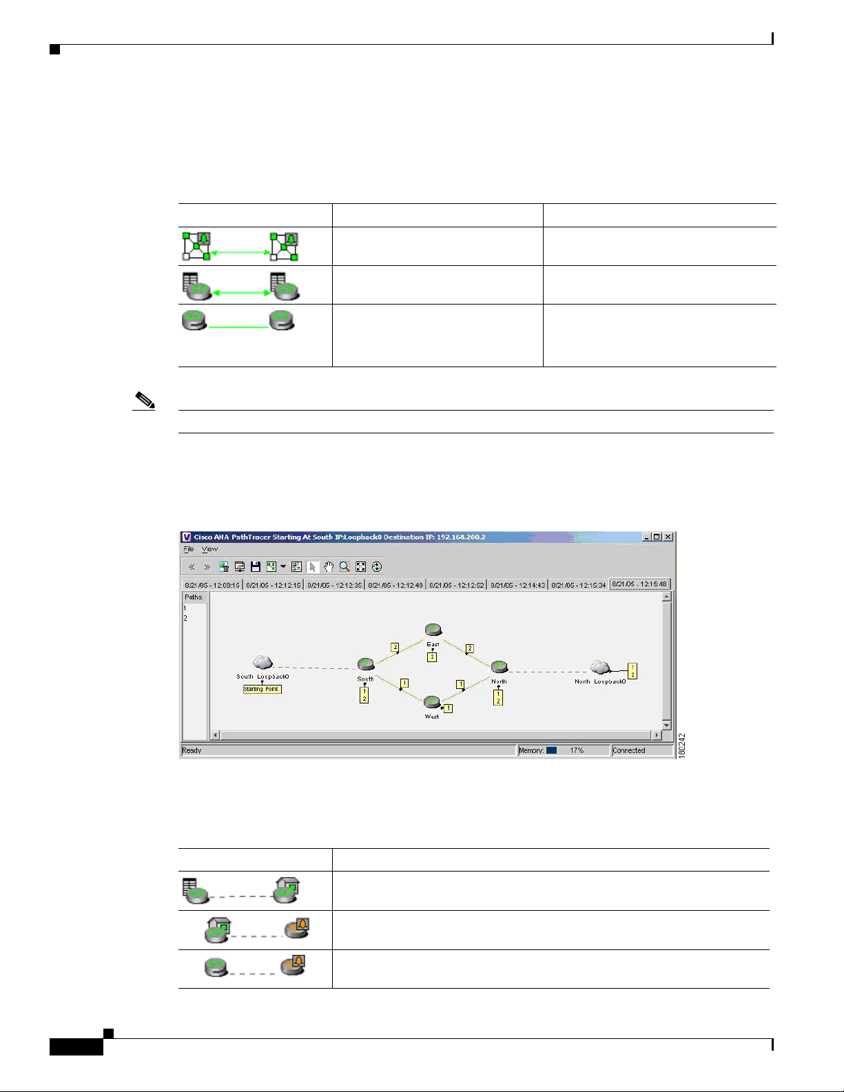
Cisco ANA shows the actual tunnel state (up or down) for the Layer 2 logical link if discovered. The link
appears with a minor severity (yellow) when the tunnel is down. Table 1-1 shows common MPLS VPN
topology map icons.
Table 1-1 Topology
Topology Example Line Description
Chapter 1 Viewing MPLS VPNs
Solid with arrows at either end. VPN topology (extranet).
Solid with arrows at either end. VPN topology between virtual routers.
Solid.
Note The link does not reflect a
Tunnel topology between LCPs.
status.
Note PE and customer edge (CE) Border Gateway Protocol (BGP) topologies are not supported.
Figure 1-1 displays several devices that are connected in a multipath VPN MPLS map in the Cisco ANA
PathTracer multipath window.
Figure 1-1 Cisco ANA PathTracer Multipath Window
1-4
Table 1-2 lists the associations that might appear on the service view map.
Table 1-2 Service View Map Associations
Association Example Description
The association between the customer site (IP interface) and the access
point on the PE.
The overall connection between the CE device and the site (IP interface),
which may cross different technologies and layers.
The overall connection between the CE device and the LCP.
Cisco Active Network Abstraction 3.6.6 MPLS User Guide
OL-19192-01
Page 15

Chapter 1 Viewing MPLS VPNs
Layer 3 VPN Map
The Layer 3 VPN service view map presents existing Layer 3 VPNs in the network. At the top level, you
can see inter-VPN (extranet) connections. Drilling down into each VPN presents the service view map,
with the following:
• Participating virtual routers and their associations with site entities.
• Site entities and their associations with CE devices.
• Connections between virtual routers and their topologies (for example, Mesh, Hub, Spoke, and
Layer 2 VPN Map
The Layer 2 VPN service view map presents existing Layer 2 VPNs in the network. At the top level, you
can see inter-VPN (extranet) associations. Drilling down into each VPN presents the service view map,
with the following:
• Connections between LCPs.
• Connections between LCPs and CEs.
• LCAs containing LCPs.
VPN Topology Connections
others).
OL-19192-01
Cisco Active Network Abstraction 3.6.6 MPLS User Guide
1-5
Page 16
VPN Topology Connections
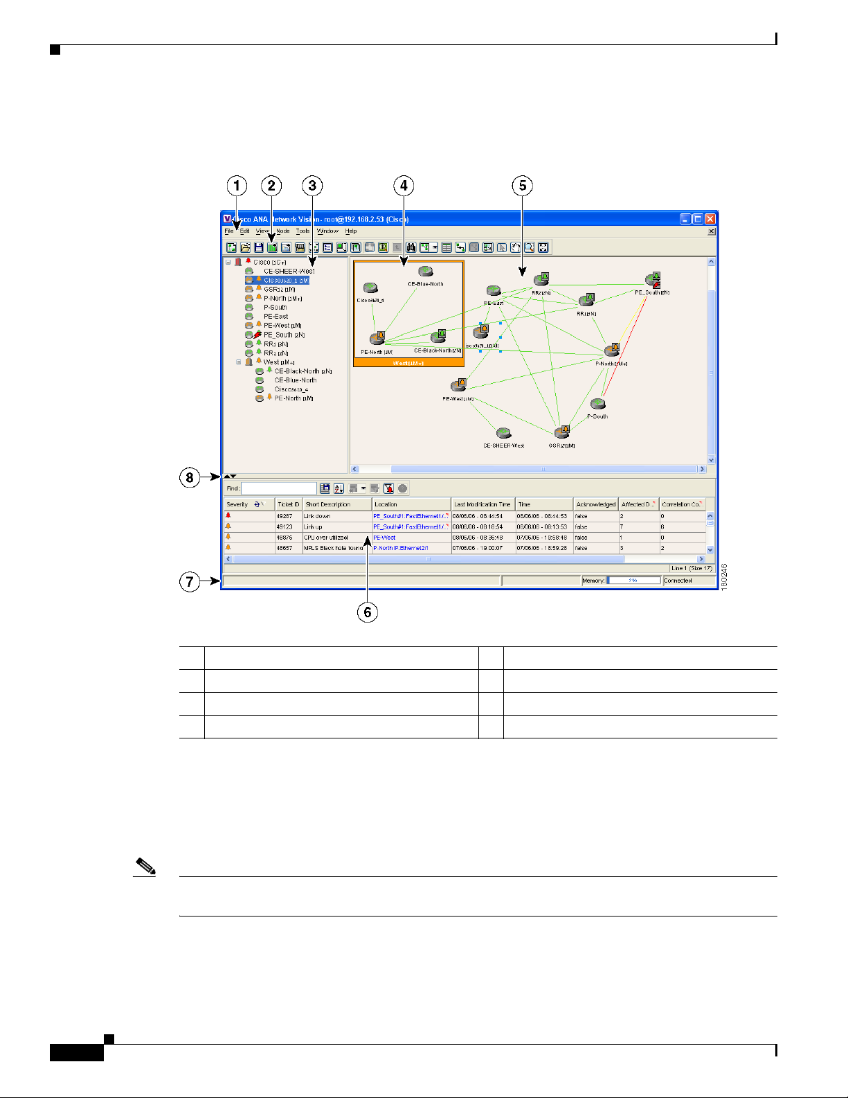
Figure 1-2 shows an example of the Cisco ANA NetworkVision window with an open service view map.
Figure 1-2 Cisco ANA NetworkVision Window
Chapter 1 Viewing MPLS VPNs
1-6
1 Menu bar 5 Map pane
2 Toolbar 6 Ticket pane
3 Tree pane 7 Status bar
4 Aggregation 8 Hide or display ticket pane buttons
The Cisco ANA NetworkVision window is divided into three areas or panes:
• Tree pane.
• Workspace, which includes the map pane, device view, and links view.
• Ticket pane.
Note The toolbar and shortcut menus are context sensitive. The available options depend on your Cisco ANA
selection.
Cisco Active Network Abstraction 3.6.6 MPLS User Guide
OL-19192-01
Page 17
Chapter 1 Viewing MPLS VPNs
Tree Pane
VPN Topology Connections
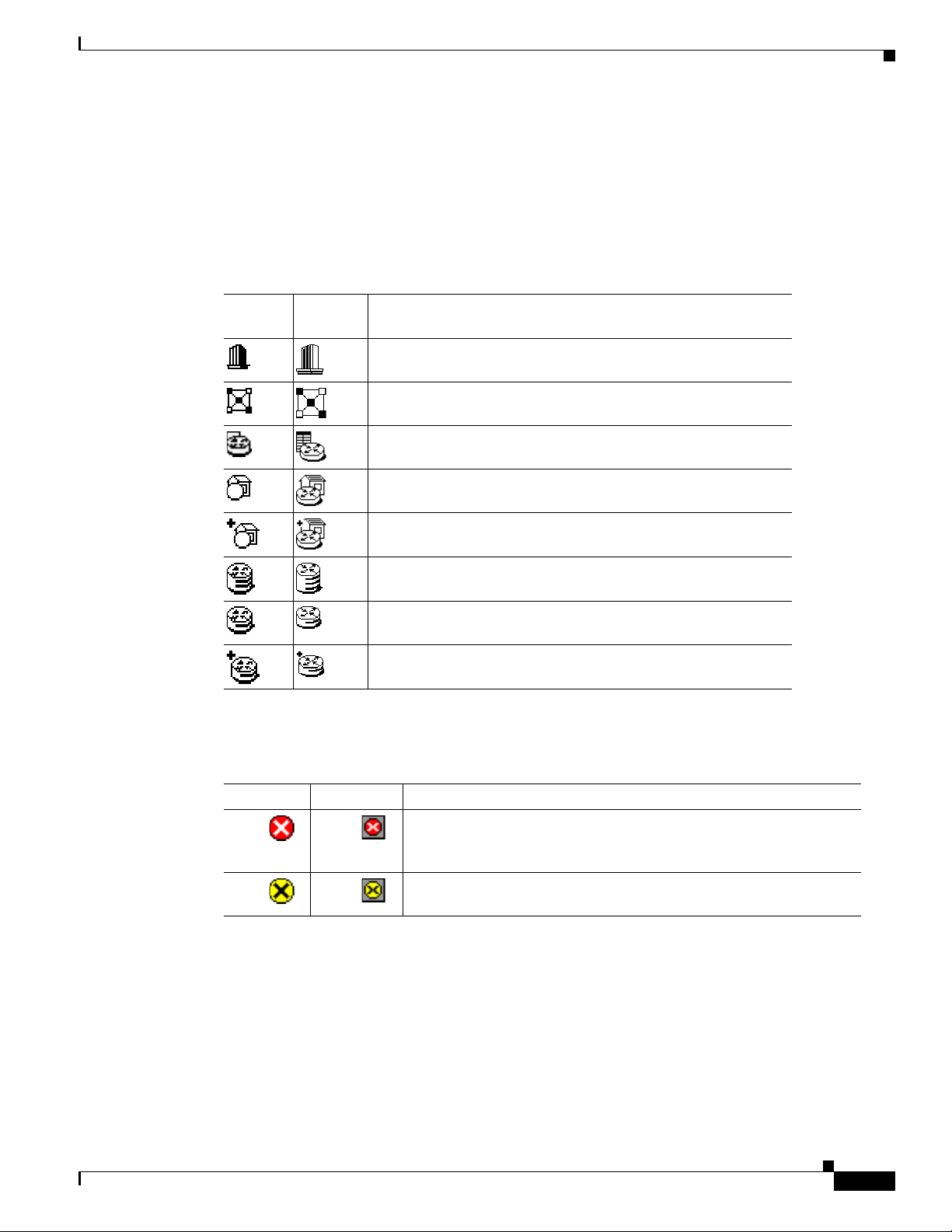
The Cisco ANA NetworkVision tree pane displays the VPN business elements in a tree and branch
representation. Each business element is represented by an icon in a color that reflects the highest alarm
severity. The icon might have a management state icon or alarm. Tab le 1-3 shows the tree and map pane
icons.
Table 1-3 Tree and Map Pane Icons
Tree
Pane
Map
Pane Represents
Root (map name) or aggregation.
VPN business element.
Virtual router business element.
Site business element.
Site business element with an actively associated, hidden CE
device.
LCA business element.
LCP business element.
LCP business element with an actively assigned tunnel edge for
a hidden CE device.
Management state icons, shown in Table 1-4, can also appear in MPLS VPN service view maps.
OL-19192-01
Table 1-4 Management State Icons
Tree Pane Map Pane Description
The reconciliation icon. The network element wrapped by this
business element does not exist; for example, the device
configuration has changed and a network problem exists.
The neighboring LCP does not exist or was not discovered.
The highest level of the tree pane displays the root or map name. The branches display the VPN and
aggregated business elements as well as their names. The Layer 3 VPN sub branch displays the virtual
routers and sites contained in the VPN along with the names of the business elements. In addition, CE
devices can also be displayed in the Layer 3 VPN sub branches. The Layer 2 VPN sub branches display
the LCAs and LCPs contained in the VPN along with the names of the business elements. In addition,
CE devices can also be displayed in the Layer 2 VPN sub branches. If you select an aggregated business
element in the tree pane, the map pane displays the business elements contained within the aggregated
business element.
Cisco Active Network Abstraction 3.6.6 MPLS User Guide
1-7
Page 18

VPN Topology Connections
Map Pane
Ticket Pane
Note Only when a device or logical part of the device is added to the service view map are the tickets of that
Chapter 1 Viewing MPLS VPNs
The Cisco ANA NetworkVision map pane displays the VPN business elements and aggregated business
elements loaded in the service view map, along with the names of the business elements. In addition, the
map pane displays the VPN topology (between the virtual routers in the VPNs) and the topology and
associations between other business elements. After you select the root in the tree pane, the service view
map displays all the VPNs.
Cisco ANA presents tickets related to the map in the ticket pane, which allows you to view and manage
the VPN tickets that have been generated. For more information about the alarms that Cisco ANA detects
and reports for Layer 2 and Layer 3 VPNs, see Chapter 7, “MPLS Network Faults.”
For more information about the ticket pane, see the Cisco Active Network Abstraction 3.6.6 User Guide.
device (for example, the link or port down ticket) displayed in the ticket pane.
1-8
Cisco Active Network Abstraction 3.6.6 MPLS User Guide
OL-19192-01
Page 19

CHAP T ER
2
Managing MPLS VPN Maps
The following topics tell you how to change service view maps by adding and removing VPNs and
connecting CE devices. They also tell you how to create and dissolve aggregations. Topics include:
• Adding a VPN to a Map, page 2-1—Describes how to add a VPN to the currently displayed service
view map.
• Removing a VPN from a Map, page 2-2—Describes how to change the service view map by
removing a VPN from the currently active map.
• Connecting a CE Device, page 2-2—Describes how to connect a CE device to its respective sites or
LCPs.
• Disconnecting a CE Device, page 2-3—Describes how to disconnect a CE device.
• Showing or Hiding a CE Device, page 2-3—Describes how to display and hide the CE device on the
service view map.
• Creating an Aggregated Node, page 2-4—Describes how to aggregate business elements according
to a logical hierarchy.
• Disaggregating an Aggregated Node, page 2-4—Describes how to disaggregate an aggregated node.
Adding a VPN to a Map
You can add VPNs to a service map if the VPNs are not currently displayed in the map.
Note Adding VPNs will affect other users if they are working with the same service view map. See the
“Creating a VPN” section on page 3-1.
To add an existing VPN to a map:
Step 1 In the Cisco ANA NetworkVision tree pane, choose the map root.
Note The Add VPN option is not enabled until you choose the root icon in the tree pane.
Step 2 From the File menu, choose Add VPN.
The Add Business Element to <Root> dialog box displays either or both of the following:
• VPNs automatically discovered by Cisco ANA.
OL-19192-01
Cisco Active Network Abstraction 3.6.6 MPLS User Guide
2-1
Page 20

Removing a VPN from a Map
• VPNs that you manually created that are not yet loaded in the map.
Step 3 Select the VPN that you want to add to the map.
Tip Press Shift or Ctrl to choose multiple adjoining or non adjoining VPNs.
Step 4 Click Add.
The VPN is loaded in the service view map displayed in the Cisco ANA NetworkVision workspace.
Step 5 Click Close.
Removing a VPN from a Map
You can remove one or more VPNs from the current active map. This change does not affect other maps.
Removing a VPN from a map does not remove it from the Cisco ANA database. The VPN will appear
in the Add Business Element to <Root> dialog box, so it can be added back to the map at any time.
When removing VPNs from maps, keep the following in mind:
• Removing a VPN will affect other users if they are working with the same service view map.
Chapter 2 Managing MPLS VPN Maps
• This option does not change the business configuration or database.
• You cannot remove virtual routers, sites, LCAs, or LCPs from the map without removing the VPN.
To remove a VPN, in the Cisco ANA NetworkVision tree or map pane, right-click the VPN and choose
Remove from Map.
The VPN is removed from the service view map along with all VPN elements such as connected CE
devices. Remote VPNs (extranets) are not removed.
Connecting a CE Device
The connect CE functionality enables you to create a symbolic link to the overall connection between
the CE device and the site (IP interface) or LCPs. The CE device belongs to the currently displayed map
only. To connect a CE device:
Step 1 Complete one of the following:
• To add a CE device to a site, choose the VPN in the Cisco ANA NetworkVision tree or map pane.
• To add a CE device to an LCP, choose the LCA.
Step 2 From the File menu, choose Add Device.
Step 3 From the Device List dialog box, choose the device that you want to add.
Step 4 Click Add Device.
The device is displayed in the tree pane and the selected map or subnetwork in the Cisco ANA
NetworkVision workspace.
2-2
Cisco Active Network Abstraction 3.6.6 MPLS User Guide
OL-19192-01
Page 21

Chapter 2 Managing MPLS VPN Maps
Note Device alarm tickets do not appear in the ticket pane of the Cisco ANA NetworkVision
workspace until the device is added to the VPN service view map.
Step 5 Click Close to close the Device List dialog box.
Step 6 Right-click the site or LCP in the tree or map pane and choose Topology > Connect CE Device.
Step 7 Right-click the device in the tree or map pane and choose Topology > Connect to Site/LCP (where Site
or LCP displays the details of the site or LCP to be connected).
The site or LCP is connected to the CE device, and the CE device is displayed in the tree and map panes.
A dashed, dark-gray line indicates the association.
Note The Topology > Connect to Site/LCP menu option is not available until after you choose the
Topology > Connect CE Device menu option.
Disconnecting a CE Device
Disconnecting a CE Device
You can disconnect a CE device from its sites or LCPs. To disconnect a CE device, right-click the
required CE device or link in the map pane and choose Topology > Disconnect CE Device.
The association with the CE device is no longer displayed in the map pane.
Showing or Hiding a CE Device
You can show the CE device for a site or LCP in the Cisco ANA NetworkVision tree and map panes. You
can also display the device associations on the service view map after the CE is connected. In addition,
you can manually add connected devices (some or all of them) to view them along with the links to sites
or LCPs.
To show a connected device:
• To show a site or LCP, right-click one of the following and choose Show CE Devices:
–
Select a site in the map pane displaying the site business element with an actively associated CE
device icon (for more information about icons see Table 1-3 on page 1-7).
–
Select an LCP in the map pane displaying the LCP business element with an actively assigned
tunnel edge for the CE device icon.
The connected devices are shown in the tree pane and map pane including the associations.
To hide a connected device:
OL-19192-01
• Right-click the site or LCP in the Cisco ANA NetworkVision tree or map pane connected to the CE
device and choose Hide Connected Devices.
Cisco Active Network Abstraction 3.6.6 MPLS User Guide
2-3
Page 22

Creating an Aggregated Node
The connected CE devices are hidden in the tree and map panes. Tab l e 2-1 shows the displayed icons.
Table 2-1 Hidden Device Icons
Icon Description
Site with one or more hidden connected devices.
LCP with one or more one hidden connected devices.
You can also manually remove the connected devices (some or all them) in order to hide them along with
the links to sites or LCPs.
Creating an Aggregated Node
Chapter 2 Managing MPLS VPN Maps
You can aggregate elements, for example, aggregate sites or aggregate sites and virtual routers. To create
an aggregation:
Step 1 Select the required business elements in the Cisco ANA NetworkVision tree or map pane using <Ctrl>
or the selection tool.
Note The Aggregate option is enabled only when multiple business elements are selected.
Step 2 From the Node menu, choose Aggregate.
The Aggregation dialog box is displayed prompting you to type a name for the aggregated node.
Step 3 In the Aggregation dialog box, enter a unique name for the aggregated node.
Step 4 Click OK.
The aggregated node is displayed in the Cisco ANA NetworkVision tree and map pane. Aggregated
nodes are displayed as a single entity using the aggregation icon.
Disaggregating an Aggregated Node
Aggregated nodes can be broken apart, or disaggregated, and their aggregated association dissolved. To
disaggregate an aggregated node:
2-4
Step 1 Select either the aggregated node branch in the tree pane or the aggregated node in the map pane.
Step 2 From the Node menu, choose Disaggregate.
Cisco Active Network Abstraction 3.6.6 MPLS User Guide
OL-19192-01
Page 23

Chapter 2 Managing MPLS VPN Maps
Step 3 Click Ye s.
The node is separated into its parts.
Disaggregating an Aggregated Node
OL-19192-01
Cisco Active Network Abstraction 3.6.6 MPLS User Guide
2-5
Page 24

Disaggregating an Aggregated Node
Chapter 2 Managing MPLS VPN Maps
2-6
Cisco Active Network Abstraction 3.6.6 MPLS User Guide
OL-19192-01
Page 25

CHAP T ER
3
Managing VPN Business Configurations
The following topics tell you how to change business configurations using the functionality provided in
service view maps. For more information about business configurations, see VPN Business
Configurations, page 1-2.
Note All operations described in this chapter affect elements on the current map. The operations do not affect
other maps.
• Creating a VPN, page 3-1—Describes how to manually create VPNs.
• Moving a Virtual Router, page 3-3—Describes how to move a virtual router (including its sites)
from one VPN to another.
• Adding a Tunnel to a VPN, page 3-3—Describes how to add tunnels to a VPN.
• Removing a Tunnel, page 3-4—Describes how to remove tunnels from a VPN.
• Creating an LCA, page 3-5—Describes how to manually create an LCA.
• Moving an LCA, page 3-5—Describes how to move an LCA to another VPN.
• Deleting an LCA, page 3-5—Describes how to delete an LCA.
• Moving an LCP, page 3-6—Describes how to move an LCP to another VPN or LCA.
• Jumping to an Adjacent LCP, page 3-6—Describes how to jump from one peer to an adjacent peer.
• Renaming a Business Element, page 3-6—Describes how to rename business elements from the
business model.
• Deleting a Business Element, page 3-7—Describes how to delete business elements from the
business model.
Creating a VPN
You can change business configurations by manually creating VPNs. The VPNs that are manually
created do not contain virtual routers and sites.
To create a VPN:
Step 1 In the Cisco ANA NetworkVision tree pane, select the map root.
Step 2 From the File menu, choose Add VPN.
Step 3 In the Add VPN to <Root> dialog box, click New.
OL-19192-01
Cisco Active Network Abstraction 3.6.6 MPLS User Guide
3-1
Page 26

Creating a VPN
Step 4 In the Create VPN dialog box, enter the following:
Step 5 Click OK.
Chapter 3 Managing VPN Business Configurations
• Name—Enter a unique name for the new VPN.
Note VPN business element names are case sensitive.
• Icon—If you want to use a custom icon for the VPN, click the button next to the Icon field and
navigate to the icon file.
Note If a path is not specified to an icon the default VPN icon is used (for more information about
icons see Table 1-3 on page 1-7).
• Description—(optional) An additional VPN description.
The new VPN is added to the VPN list in the Add VPN to <Root> dialog box.
For more information about loading the newly created VPN in the service view map, see Adding a VPN
to a Map, page 2-1.
3-2
Cisco Active Network Abstraction 3.6.6 MPLS User Guide
OL-19192-01
Page 27

Chapter 3 Managing VPN Business Configurations
Moving a Virtual Router
You can move a virtual router (including its sites) from one VPN to another after you create a VPN and
add it to the service view map.
Note Moving a virtual router moves all of its sites as well.
To move a virtual router:
Step 1 In the Cisco ANA NetworkVision tree pane or the map pane, right-click the virtual router and choose
Edit > Move selected.
Step 2 Right-click the required VPN in the tree or the map pane to where you want to move the virtual router
and choose Edit > Move here.
Caution Moving a virtual router from one VPN to another affects all users who have the virtual router
loaded in their service view map.
Moving a Virtual Router
The virtual router and its sites are displayed under the selected VPN in the tree pane and in the map pane.
Adding a Tunnel to a VPN
You can add tunnels or partially configured tunnels to a VPN. LCPs with a missing peer are marked with
the stranded icon. (For more information about icons see Tabl e 1 - 3.) Each tunnel can be associated with
only one VPN.
Note The topology state between LCPs is a logical link. It does not reflect the actual state of the network.
You can do either of the following:
• Add a tunnel (LCP) to an LCA that has been manually created (see Creating an LCA, page 3-5).
• Add a tunnel (LCP) directly to a VPN, in which case the LCA is automatically created beneath the
VPN.
To add a tunnel to a VPN, complete the following steps.
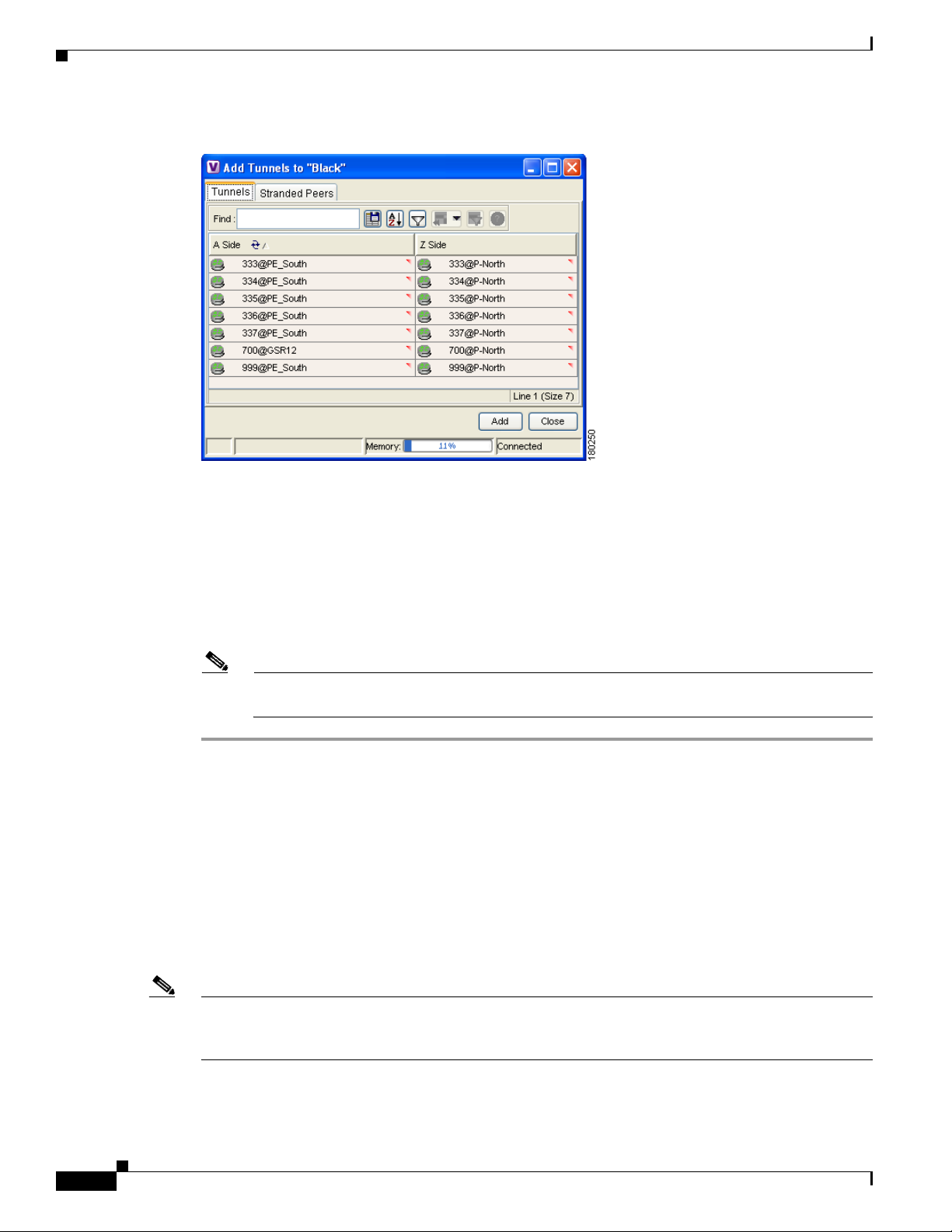
Step 1 In the Cisco ANA NetworkVision tree or map pane, right-click an LCA or VPN and choose Top o lo g y >
Add Tunnel.
The Add Tunnels dialog box (Figure 3-1) displays tunnels not currently attached to a VPN. The Tunnels
tab displays the list of pseudowire tunnels (including both tunnel edges). The Stranded Peers tab displays
the list of partially configured tunnel edges, so you can add an LCP without its peer, for example, if a
tunnel is partially managed, an agent fails to load, or a device is incorrectly configured.
OL-19192-01
Cisco Active Network Abstraction 3.6.6 MPLS User Guide
3-3
Page 28
Removing a Tunnel
Chapter 3 Managing VPN Business Configurations
Figure 3-1 Add Tunnels Dialog Box
Step 2
Select the tunnel or stranded peer and click Add.
One of the following occurs:
• If the tunnel or stranded peer is added under an LCA, the link between the peers appears in the map
pane.
• If the tunnel or stranded peer is added under a VPN, Cisco ANA detects the starting point of the
PWE3 tunnel edges and groups all the LCPs that start at the same device together into an LCA
(aggregation) under the VPN.
Note If a tunnel exists between VPNs, for example, an extranet tunnel, add a tunnel to one VPN and
then move one LCP (peer) to the VPN with which you want to create the extranet tunnel.
Removing a Tunnel
You can remove a tunnel that was added to an LCA or VPN. To remove a tunnel, in the Cisco ANA
NetworkVision tree or map pane, right-click the LCA or VPN and choose Topology > Remove Tunnel.
Both tunnel sides are removed from the map. You view them in the Add Tunnels dialog box. If the
deleted tunnel formed part of an LCA that was created manually, the LCA is still displayed in the tree
or map pane. If the deleted tunnel formed part of an LCA that was created automatically, the LCA is
removed from the tree or map pane, provided no other LCPs exist in the LCA.
3-4
Note You cannot view MPLS TE tunnels in VPN service view maps. However; you can view the device and
topology information. For more information, see the “Viewing MPLS TE Tunnel Information” section
on page 5-13.
Cisco Active Network Abstraction 3.6.6 MPLS User Guide
OL-19192-01
Page 29

Chapter 3 Managing VPN Business Configurations
Creating an LCA
You can manually create an LCA and populate it by moving LCPs and tunnels to it. Refer to the “Moving
an LCP” section on page 3-6 and the “Adding a Tunnel to a VPN” section on page 3-3.
To create an LCA:
Step 1 In the Cisco ANA NetworkVision window tree or map pane, right-click the VPN and choose Create
LCA.
Step 2 In the Create LCA dialog box, enter a unique name for the new LCA.
Step 3 Click OK.
The new LCA is created. It appears in the tree pane in the Cisco ANA NetworkVision window, beneath
the selected VPN, and also appears in the map pane.
Moving an LCA
Creating an LCA
You can move the LCA to another VPN in the service view map. When you move an LCA, all the LCPs
it contains also move.
To move an LCA:
Step 1 In the Cisco ANA NetworkVision tree or map pane, right-click the LCA and choose
Edit > Move selected.
Step 2 Right-click the VPN to which you want to move the LCA and choose Edit > Move here.
The LCA moves to the selected VPN and is displayed in the tree and map panes for the selected VPN.
Note All the LCPs move with the LCA.
Deleting an LCA
You can delete an LCA if it was manually created and either has no LCPs or all the LCPs have
reconciliation icons. (You can also move the LCA to another VPN using the “Jumping to an Adjacent
LCP” section on page 3-6.)
To delete the LCA:
OL-19192-01
Step 1 In the Cisco ANA NetworkVision tree or map pane, right-click the required LCA and choose Delete.
Step 2 Click Ye s on the confirmation.
The selected LCA is deleted from the database and service view maps of all users.
Cisco Active Network Abstraction 3.6.6 MPLS User Guide
3-5
Page 30

Moving an LCP
Moving an LCP
You can move an LCP to another VPN or LCA in the service view map.
To move an LCP:
Step 1 In the Cisco ANA NetworkVision tree or map pane, right-click the LCA and choose
Edit > Move selected.
Step 2 Right-click the VPN or LCA to which you want to move the LCP and choose Edit > Move here.
The LCP moves to the VPN or LCA and is displayed in the tree and map panes of the selected VPN or
LCA.
Note If an LCP is moved to a VPN, an LCA is automatically created for it.
Chapter 3 Managing VPN Business Configurations
Jumping to an Adjacent LCP
If a service view map displays multiple tunnels, you can quickly access the selected LCP peer appearing
in the same map.
To jump to the adjacent LCP, in the Cisco ANA NetworkVision tree or map pane, right-click the required
LCP and choose Jump to Adjacent.
The adjacent LCP is highlighted in the tree pane and map pane.
Renaming a Business Element
To rename business elements in service view maps:
Step 1 In the Cisco ANA NetworkVision tree or map pane, right-click the business element and choose
Rename.
Step 2 In the Rename Node dialog box, type a new name.
Step 3 Click OK.
The changed business element name appears in the Cisco ANA NetworkVision tree and map panes.
3-6
Note Renaming a business element affects all users who have the business element loaded in their
service view maps.
Cisco Active Network Abstraction 3.6.6 MPLS User Guide
OL-19192-01
Page 31

Chapter 3 Managing VPN Business Configurations
Deleting a Business Element
You can delete business elements from the business model (database). However, if you delete a business
element from the database, it can no longer be viewed in the Add Business Element to <Root> dialog
box. You generally delete business elements only when the physical elements no longer exist.
Caution Deleting business elements affects all users who have the business elements loaded in their service view
map.
Table 3-1 lists the requirements that must be met before you can delete the required business element.
Table 3-1 Business Element Deletion Requirements
Business Element Requirements
Layer 3 VPN The VPN has no virtual routers, or, if it does, the virtual routers and sites display
the reconciliation icon.
Virtual router The virtual router contains no VRFs, sites, or interfaces, or, if it does, the VRFs,
sites, and interfaces display the reconciliation icon.
Site No sites or interfaces are connected or bound to the VRF, or, if they are connected,
they display the reconciliation icon.
Layer 2 VPN The Layer 2 VPN has no LCPs, or, if it does, the LCPs display the reconciliation
icon.
LCA The LCA has no LCPs, or, if it does, the LCPs display the reconciliation icon.
Deleting a Business Element
To delete a business element.
Step 1 Verify that the business element meets all requirements specified in Tab le 3-1. You will not be able to
delete the elements if all requirements are not met.
Step 2 In the Cisco ANA NetworkVision tree or map pane, right-click the business element, and choose Delete.
Step 3 In the confirmation message, click Yes to delete the currently selected element, or click Ye s t o A l l to
delete multiple selected elements.
The selected business element is deleted from the business configuration of all users.
OL-19192-01
Cisco Active Network Abstraction 3.6.6 MPLS User Guide
3-7
Page 32

Deleting a Business Element
Chapter 3 Managing VPN Business Configurations
3-8
Cisco Active Network Abstraction 3.6.6 MPLS User Guide
OL-19192-01
Page 33

Viewing MPLS VPN Properties
The following topics tell you how to use Cisco ANA to view the properties of VPNs, sites, virtual
routers, and VRF instances. Topics include:
• Viewing VPN Properties, page 4-1—Tells you how to view VPN properties.
• Viewing Site Properties, page 4-1—Tells you how to view site properties.
• Viewing Virtual Router Properties, page 4-2—Tells you how to view virtual router properties. In
addition, it describes the VRF table and the display of VRF egress and ingress adjacents.
• Viewing VRF Properties in the Inventory Window, page 4-5—Tells you how to view VRF and
pseudowire tunnels as well as specific VPN logical inventory items.
• Working with the VPN Service Overlay, page 4-7—Tells you how to select and display an overlay,
display or hide a previously defined overlay, and display or hide the callouts for map pane links.
Viewing VPN Properties
CHAP T ER
4
To view the properties of a VPN:
Step 1 In the Cisco ANA NetworkVision tree or map pane, right-click the VPN and choose Properties.
Step 2 In the VPN Properties window, view the following VPN properties:
• Name—The name of the VPN.
• ID—The unique key automatically assigned to the VPN.
Step 3 Click Close to close the VPN Properties dialog box.
Viewing Site Properties
Cisco ANA enables you to view site properties including the interfaces that are configured on the PE
device. The displayed properties reflect the configuration Cisco ANA automatically discovered for the
device.
To view site properties:
Step 1 In the Cisco ANA NetworkVision tree or map pane, right-click a site and choose Properties.
OL-19192-01
Cisco Active Network Abstraction 3.6.6 MPLS User Guide
4-1
Page 34

Viewing Virtual Router Properties
Step 2 In the Router IP Interface Properties window, view the following site properties:
• Name—The name of the site; for example, ATM4/0.100(10.0.0.1) is a combination of the interface
name and IP address used to reach the site.
• Mask—The mask of the specific network.
• Sending Alarms—Whether the alarm for the required port has been enabled (true) or disabled
(false).
• IP Address—The IP address of the interface.
• State—The state of the interface, either Up or Down.
• Addresses—A table that displays PE-side IP interface details. Address properties include:
–
Note If the site is an IPv6 VPN over MPLS, IPv6 addresses will be displayed. For information
–
–
Chapter 4 Viewing MPLS VPN Properties
Subnet—A combination of the IP address and the subnet mask.
about IPv6 addresses, see the “IPv6 Addressing” section on page 6-6.
Type—The address type, for example, Primary, Secondary, IPv6 Unicast.
Sending Alarms—Indicates whether the interface is sending alarms.
Step 3 When finished, click the Router IP Interface Properties window Close button.
Viewing Virtual Router Properties
Cisco ANA NetworkVision enables you to view VRF properties including the VRF route distinguisher,
import and export route targets, and any provisioned sites and VRF routes.
To view virtual router properties:
Step 1 Right-click a virtual router in the Cisco ANA NetworkVision tree or map pane and choose Properties.
The VRF Properties window (Figure 4-1) is displayed.
4-2
Cisco Active Network Abstraction 3.6.6 MPLS User Guide
OL-19192-01
Page 35
Chapter 4 Viewing MPLS VPN Properties
5
6
1 2 3 4
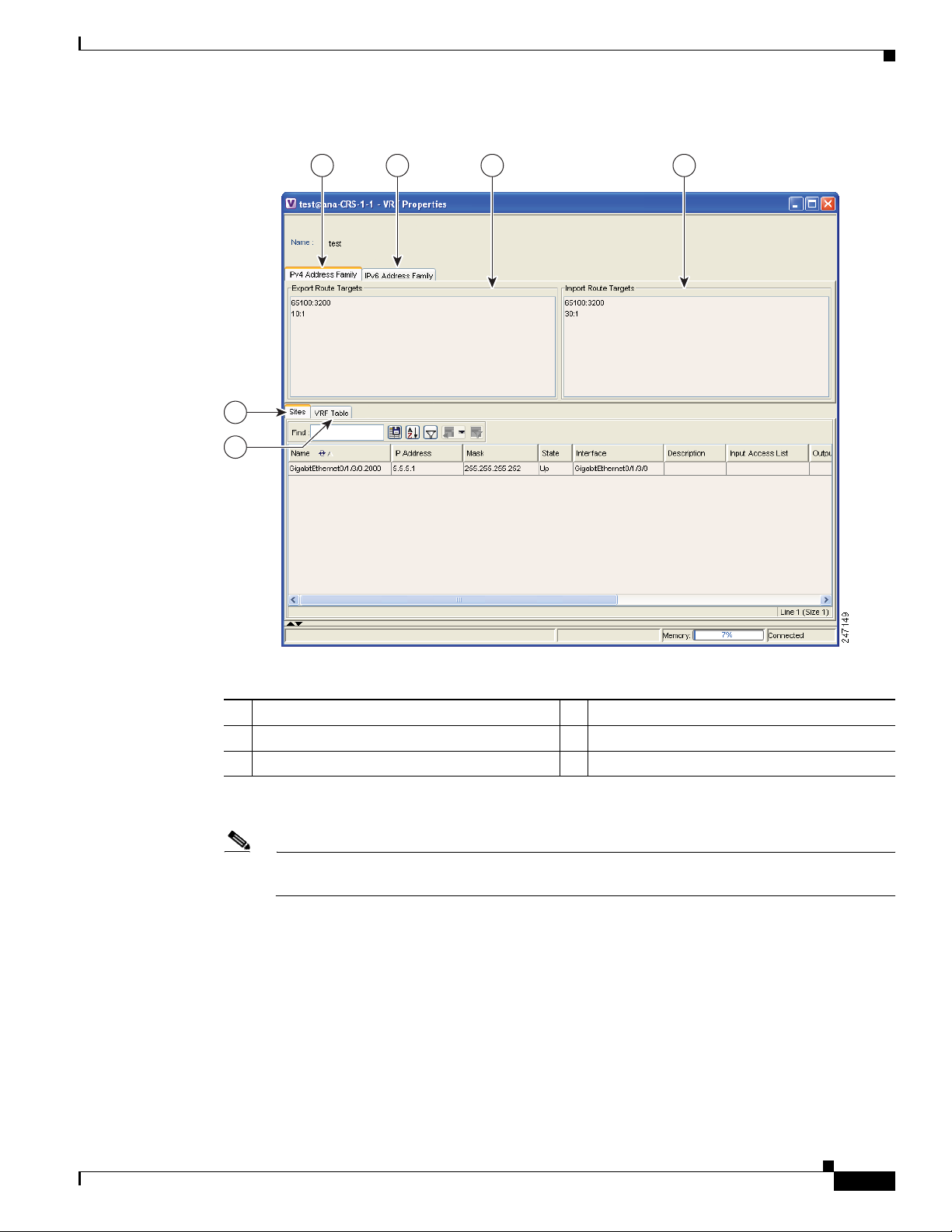
Figure 4-1 VRF Properties
Viewing Virtual Router Properties
1 IPv4 Address Family tab 2 IPv6 Address Family tab
3 Export route targets 4 Import route targets
Step 2
5 Sites tab 6 VRF table
In the VRF Properties window, view the following VRF properties:
Note The VRF Properties window only displays properties and attributes that are provisioned in the
VRF. You might not see all the fields and tabs described here.
• Route Distinguisher—The route distinguisher configured in the VRF. (The Route Distinguisher field
is not shown in Figure 4-1.)
• IPv4 Address Family—Route targets are automatically assigned to IPv4 address family.
• IPv6 Address Family—If you are running an IPv6 VPN over MPLS implementation, you can assign
route targets to IPv6 address families, in which case, the IPv6 Address Family tab will appear. For
information about 6VPE and IPv6 address family procedures, refer to Chapter 6, “IPv6 VPN over
MPLS.”
• Export Route Targets—Displays the export route targets contained by the VRF.
• Import Route Targets—Displays the import route targets contained by the VRF.
Cisco Active Network Abstraction 3.6.6 MPLS User Guide
OL-19192-01
4-3
Page 36

Viewing Virtual Router Properties
• Sites—Displays the interfaces connected to the VRF. Properties include:
–
–
–
–
–
–
–
–
–
Chapter 4 Viewing MPLS VPN Properties
Interface—A hyperlink that displays the inventory window for the IP interface linked to the site
on the PE side.
Name—The name of the site; for example, ATM4/0.100(10.0.0.1) is a combination of the
interface name and IP address used to reach the site.
IP Address—The IP address of the interface.
Mask—The subnet mask.
State—The state of the subinterface, either Up or Down.
Description—A description of the interface.
Input Access List—The access list applied to the inbound traffic of the interface.
Output Access List—The access list applied to the outbound traffic of the interface.
Rate Limits—Measures traffic for the IP interfaces on Cisco devices, including the average rate,
normal burst size, excess burst size, conform-action and exceed action.
Note Input access list, output access list, and rate limits parameters apply only to Cisco IOS
devices.
–
Site Name—The name of the business element to which the interface is attached.
• VRF Table—Contains the VRF routing table for the device. The table is a collection of routes that
are available or reachable to all the destinations or networks in the VRF. In addition, the forwarding
table also contains MPLS encapsulation information. VRF routing properties include:
–
Destination—The destination of the specific network.
–
Mask—The subnet mask of the specific network.
–
Next Hop—The next routing hop. This is the next CE address on the routing path. This field is
empty when the routing entry goes to the PE.
–
BGP Next Hop—The Border Gateway Protocol (BGP) next hop. This is the PE address from
where to continue to get to a specific address. This field is empty when the routing entry goes
to the CE.
–
VRF Out Label—The label sent with MPLS traffic.
–
VRF In Label—The label that is expected when MPLS traffic is received.
–
MPLS Label—The MPLS label.
–
Type—The type can be direct (local) or indirect.
–
Routing Protocol—The routing protocol used to communicate with the other sites and VRFs,
either BGP or local.
–
Outgoing Int. Name—The name of the outgoing interface; displayed if the Routing Protocol
type is local.
Step 3 When finished, press Ctrl + F4 to close the VRF Properties window.
4-4
Cisco Active Network Abstraction 3.6.6 MPLS User Guide
OL-19192-01
Page 37

Chapter 4 Viewing MPLS VPN Properties
Note You can also open a VRF table by right-clicking the virtual router in the Cisco ANA NetworkVision tree
or map pane and selecting Open VRF Table. For more information about the columns displayed in the
VRF Table window, see Viewing Virtual Router Properties, page 4-2.
Displaying VRF Egress and Ingress Adjacents
Cisco ANA enables you to view the exporting and importing neighbors by displaying the VRF egress
and ingress adjacents. In addition, you can view the connectivity between the VRFs for the route targets
and view their properties. For example, if VRF A retrieved route target import X, you can view all VRFs
that export X as a route target whether it is in the same or another VPN.
To display the VRF egress and ingress adjacents:
Step 1 Right-click the virtual router in the Cisco ANA NetworkVision tree and choose Show VRF Egress
Adjacents/Show VRF Ingress Adjacents. The Adjacents window is displayed.
Step 2 In the Adjacents dialog box, view the ingress and egress adjacent properties:
Viewing VRF Properties in the Inventory Window
• Name—The name of the VRF as it appears in the device.
• Route Distinguisher—The route distinguisher configured in the VRF.
Note Selecting a specific VRF in the Cisco ANA NetworkVision tree pane displays the VRF
properties. For more information, see Viewing Virtual Router Properties, page 4-2.
Step 3 When finished, press Ctrl + F4 to close the Adjacents window.
Viewing VRF Properties in the Inventory Window
You can view VRFs that are provisioned in individual devices by displaying the device inventory view
and navigating to the VRF logical inventory, as shown in Figure 4-2.
OL-19192-01
Cisco Active Network Abstraction 3.6.6 MPLS User Guide
4-5
Page 38
Viewing VRF Properties in the Inventory Window
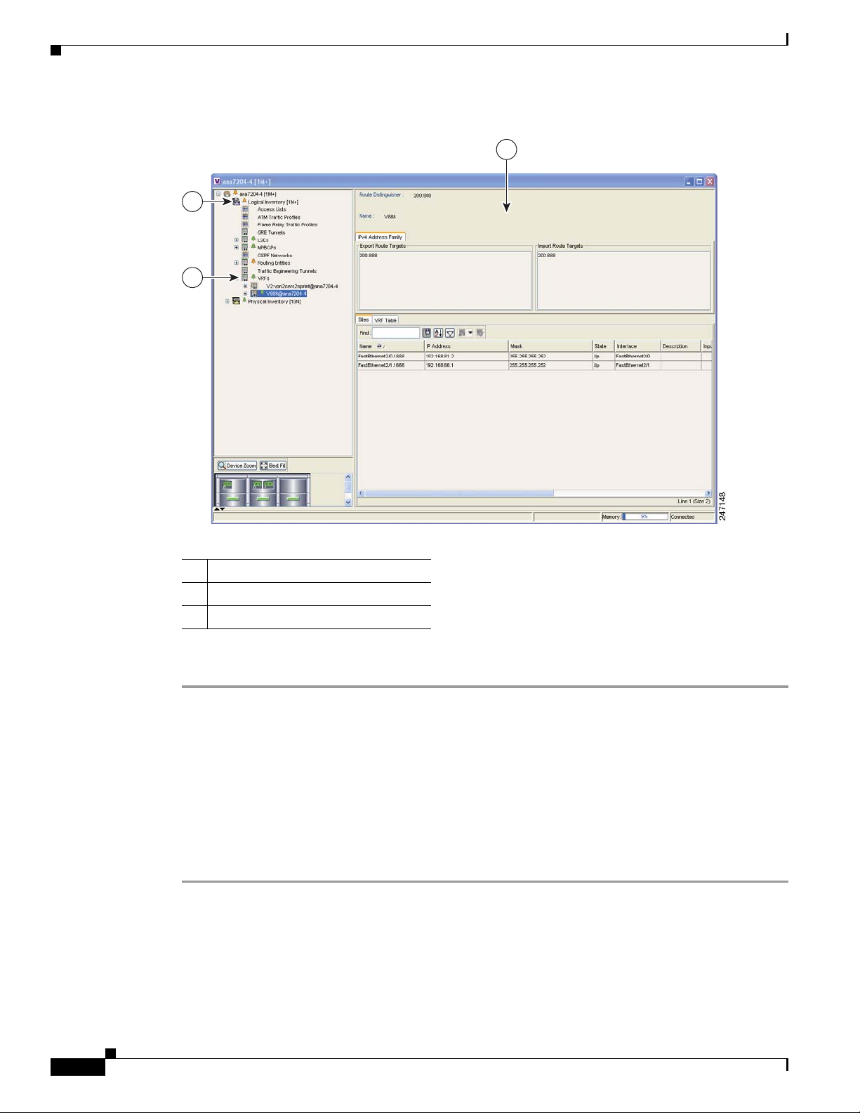
Figure 4-2 VRF Properties From a Device Inventory Window
1
2
Chapter 4 Viewing MPLS VPN Properties
3
1 Logical Inventory
2 VRFs provisioned on the device
3 VRF properties
To view VRFs provisioned on a device:
Step 1 Right-click a device in the Cisco ANA NetworkVision tree or map pane and choose Inventory.
Step 2 In the tree pane, expand the Logical Inventory tree to display the VRFs.
Step 3 Do either of the following:
• Double-click the VRF whose properties you want to view.
• Right-click the VRF and choose Properties.
The VRF properties appear in the Cisco ANA NetworkVision workspace. For descriptions of the VRF
properties, see “Viewing Virtual Router Properties” procedure on page 4-2.
Step 4 When finished, When finished, press Ctrl + F4 to close the inventory window.
4-6
Cisco Active Network Abstraction 3.6.6 MPLS User Guide
OL-19192-01
Page 39

Chapter 4 Viewing MPLS VPN Properties
Working with the VPN Service Overlay
In addition to network and service view maps, you can select and display an overlay of a specific VPN
on top of the devices displayed on the network map. The overlay is a snapshot of the network that
visualizes the flows between the sites and tunnel peers. When one network VPN is selected in the
network map, the PE routers, MPLS routers, and physical links that carry the label switched path (LSP)
used by the VPN are highlighted in the network map. All the devices and links that are not part of the
VPN are grayed out.
The VPN service overlay allows you to isolate the parts of a network that are being used by a particular
service. This information can then be used for troubleshooting. For example, the overlay can highlight
configuration or design problems when bottlenecks occur and all the site interconnections use the same
link.
Note If the routing information changes after the overlay is run, the changes will not appear in the current
overlay.
The following topics describe the following overlay functionality information:
• Choosing an Overlay, page 4-7—Describes how to select and display an overlay of a specific VPN
on top of the devices displayed on the physical network map.
• Displaying or Hiding Overlays, page 4-8—Describes how to display or hide a previously defined
overlay of a specific VPN on top of the physical devices displayed on the physical network map.
Working with the VPN Service Overlay
• Displaying or Hiding Callouts, page 4-8—Describes how to display or hide the callouts for every
link in the map pane in order to display related information.
Choosing an Overlay
You can display an overlay of a specific VPN on top of the devices displayed on the physical network
map in the map pane.
To choose an overlay:
Step 1 Display the network map for which you want to create an overlay in Cisco ANA NetworkVision.
Step 2 On the toolbar, click Choose Overlay.
The Choose Overlay dialog box displays the available VPNs in the network.
Step 3 Select a VPN, then click OK.
The PE routers, MPLS routers, and physical links used by the selected VPN are highlighted in the
network map. The VPN name is displayed in the title of the window.
Note The overlay is a snapshot taken at a specific point in time. To update the overlay, you must select and
run it again.
OL-19192-01
You can hide previously defined VPN network information in the map pane using the appropriate toolbar
buttons:
Cisco Active Network Abstraction 3.6.6 MPLS User Guide
4-7
Page 40
Working with the VPN Service Overlay
• Overlay information, such as link and layer details
• Callouts for the VPN network
Displaying or Hiding Overlays
You can quickly display or hide a previously defined overlay of a specific VPN on top of the physical
devices displayed on the network map in the map pane.
To show or hide the overlay:
Step 1 Select and display the required network map in the Cisco ANA NetworkVision window.
Step 2 On the toolbar, click Show Overlay.
Note The Show Overlay toolbar button is a toggle. When selected, the overlay is displayed. When
deselected, the overlay is hidden.
Chapter 4 Viewing MPLS VPN Properties
Displaying or Hiding Callouts
You can display or hide the callouts for the links displayed in the map pane to show the details of the
sites that are interconnected through the selected links.
Note Multiple callouts can open at the same time.
The Callouts window (Figure 4-3) enables you to view the VPN traffic connections for a specific link
(either bidirectional or unidirectional). In the P-North - > PE-West example, the table displays the traffic
connections from one site or LCP to another.
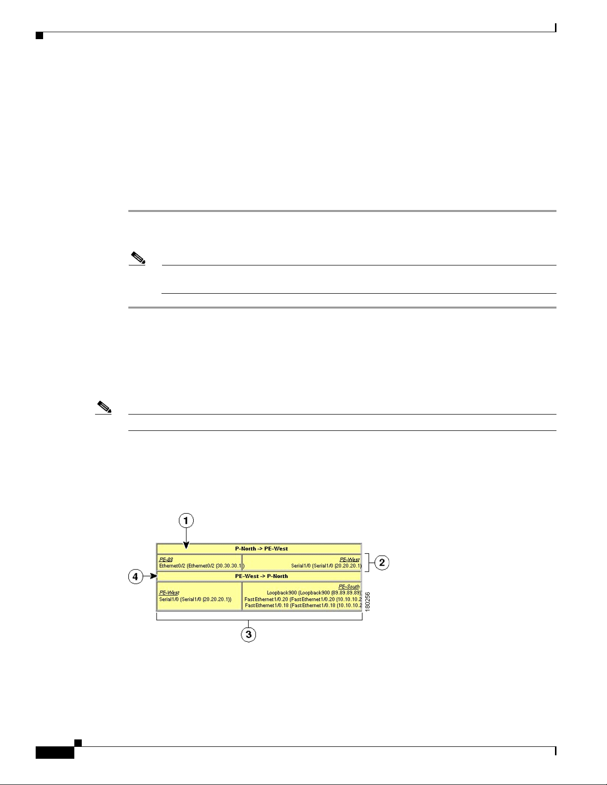
Figure 4-3 Callouts Dialog Box
4-8
Cisco Active Network Abstraction 3.6.6 MPLS User Guide
OL-19192-01
Page 41

Chapter 4 Viewing MPLS VPN Properties
Working with the VPN Service Overlay
1 Details of the link and the direction. In this
example, the link is from P-North to PE-West.
3 Details of sites using the link and
interconnections. In this example, the site
PE-West is connected to all sites on PE-South.
2 Details of the sites using the link and
interconnections. In this example, the site
4 Details of the link and the direction. In this
example, the link is from PE-West to P-North.
PE-88 is connected to site PE-West.
To display or hide the callouts:
Step 1 Select and display the required network map with an overlay of the specific VPN in the map pane of the
Cisco ANA NetworkVision window.
Step 2 Right-click the required link in the map pane and choose Show Callouts.
Step 3 To hide the callouts, right-click the link in the map pane that is displaying the callouts and choose Hide
Callouts.
OL-19192-01
Cisco Active Network Abstraction 3.6.6 MPLS User Guide
4-9
Page 42

Working with the VPN Service Overlay
Chapter 4 Viewing MPLS VPN Properties
4-10
Cisco Active Network Abstraction 3.6.6 MPLS User Guide
OL-19192-01
Page 43

CHAP T ER
5
Viewing MPLS Logical Inventory
The following topics describe the device logical inventory specific to MPLS VPNs including routing
entities, LSEs, BGP neighbors, Multiprotocol BGP (MP-BGP), VRF instances, and pseudowire and TE
tunnels. Topics include:
• MPLS VPN Logical Inventory Overview, page 5-1—Introduces the concepts of physical and logical
inventory.
• Viewing MPLS VPN Properties, page 5-2—Describes MPLS VPN logical inventory properties
viewed from the inventory window including routing entities, label switched entities, MP-BGP
properties, and VRF properties.
• Viewing Port Configuration, page 5-11—Describes port configuration information.
• Viewing Pseudowire End-to End Emulation Tunnels, page 5-12—Describes the Layer 2 pseudowire
tunnel properties.
• Viewing MPLS TE Tunnel Information, page 5-13—Describes the TE tunnel properties.
• Viewing Access List Information, page 5-14—Describes access list item properties.
Note For a general description of logical inventory and the inventory window, see the Cisco Active Network
Abstraction 3.6.6 User Guide.
MPLS VPN Logical Inventory Overview
Every NE managed by Cisco ANA is assigned to an autonomous virtual network element (VNE). The
VNE continuously investigates the NE status and configuration so that Cisco ANA can display an
accurate virtual model of both the NE and the network in which the NE resides.
VNEs continuously update an NE’s physical and logical inventory. You can view an NE’s physical and
logical inventory in the Cisco ANA device inventory window. The physical inventory contains all the NE
physical components (and their properties) such as chassis, shelves, cards, and ports. The VNE detects
status changes or the addition or removal of components (such as a card) and reflects the changes in the
physical inventory.
Cisco ANA VNEs also investigate the logical inventory of each device. The logical inventory reflects
dynamic data such as configurations, forwarding, and service-related components including traffic
profiles. The logical inventory also displays virtual circuits, cross-connect tables, routing, bridging, and
LSE tables, and other logical elements. Cisco ANA NetworkVision displays the physical and logical
inventory and allows you to drill down to detailed physical and logical inventory views.
Cisco Active Network Abstraction 3.6.6 MPLS User Guide
OL-19192-01
5-1
Page 44

Viewing MPLS VPN Properties
Viewing MPLS VPN Properties
Cisco ANA maintains a real-time, autodiscovered, physical and logical inventory of the network
elements and the relationships among them. Cisco ANA automatically reflects every addition, deletion,
and modification that occurs in the network. MPLS VPN logical inventory information displayed in the
inventory window changes according to the item selected in the tree pane.
To view the Cisco ANA inventory window:
Step 1 Right-click a device in the Cisco ANA NetworkVision tree or map pane and choose Inventory.
The device logical and physical inventories are presented in the inventory window (Figure 5-1). The
window title bar displays the name of the device whose logical and physical properties are displayed.
The tree pane displays the logical and physical inventory categories in tree and branch representation. If
you choose Logical Inventory or Physical Inventory in the tree pane, the logical and physical container
categories appear in the Cisco ANA tree pane. For logical inventory, the containers are traffic containers,
forwarding component containers, and tunnel containers.
The properties pane (located in the Cisco ANA window workspace) displays physical and logical
inventory information relating to the properties of the item selected in the tree pane.
Step 2 To view MPLS VPN logical inventory properties, do one of the following in the Cisco ANA Logical
Inventory tree pane:
• Click an MPLS VPN logical inventory branch to display the MPLS VPN logical inventory properties
in the Cisco ANA workspace, or
Chapter 5 Viewing MPLS Logical Inventory
• Double-click the last MPLS VPN logical inventory tree branch to display the logical inventory
properties appear in a separate [logical inventory branch name] Properties window.
5-2
Cisco Active Network Abstraction 3.6.6 MPLS User Guide
OL-19192-01
Page 45

Chapter 5 Viewing MPLS Logical Inventory
3
4
21
Figure 5-1 Inventory Window
Viewing MPLS VPN Properties
1 Device inventory window 3 Logical inventory
2 Logical inventory container groups 4 Physical inventory
Step 3
Step 4 When finished, press Ctrl + F4 to close the inventory window.
To view the specific MPLS VPN properties, see the following sections:
• Viewing Routing Entities, page 5-4
• Viewing the ARP Table, page 5-5
• Viewing Rate Limit Information, page 5-5
• Label Switching Table Tab, page 5-6
• Traffic Engineering LSPs Tab, page 5-7
• LDP Neighbors Tab, page 5-7
• Viewing MP-BGP Information, page 5-9
OL-19192-01
Cisco Active Network Abstraction 3.6.6 MPLS User Guide
5-3
Page 46

Viewing MPLS VPN Properties
Viewing Routing Entities
The Routing Entity logical inventory branch displays the following routing entity information:
• Changes Number—The number of changes to the currently displayed routing entity.
• Name—The name of the routing entity.
The IP Interfaces tab includes the following information:
• Name—The site name; for example, ATM4/0.100(10.0.0.1) is a combination of the interface name
and IP address used to reach the site.
• IP Address—The IP address of the interface.
• Mask—The details of the dotted decimal mask.
• State—The state of the subinterface, either Up or Down.
• Interface—The interface name.
• Description—A description of the interface.
• Input Access List—If an input access list is assigned to an IP interface, the list is shown as an IP
interface property, and a hyperlink highlights the related access list in the Access List table. When
an access list is assigned to the inbound traffic on an IP interface, the actions assigned to the packet
are performed. For information about actions, see Viewing Access List Information, page 5-14.
• Output Access List—If an output access list is assigned to an IP interface, the list is shown as an IP
interface property, and a hyperlink highlights the related access list in the Access List table. When
an access list is assigned to the outbound traffic on an IP interface, the actions assigned to the packet
are performed. For information about actions, see Viewing Access List Information, page 5-14.
• Rate Limits—If a rate limit is configured on an IP interface, the limit is shown as an IP interface
property. This option is checked when a rate limit is defined on the IP interface, meaning the access
list is a rate limit access list. IP interface traffic is measured and includes the average rate, normal
burst size, excess burst size, conform action, and exceed action.
Chapter 5 Viewing MPLS Logical Inventory
5-4
Note Double-clicking a row displays the properties of the IP interface. When a rate limit is
configured on the IP interface, the Rate Limits tab is displayed. For more information about
rate limits, see Viewing Rate Limit Information, page 5-5.
Note The Input Access, Output Access, and Rate Limits parameters apply only to Cisco IOS
devices.
• IP Sec Map Name—The IP Security (IPSec) crypto map name.
• Site Name—The name of the business element to which the interface is attached.
• Sending Alarms—This option is currently unavailable.
The Routing Table tab displays the following information:
• Destination—The destination of the specific network.
• Next Hop—The CE router address from which to continue to get to a specific address. This field is
empty when the routing entry goes to a PE router.
• Mask—The mask of the specific network.
• Type—The type can be direct (local) or indirect.
Cisco Active Network Abstraction 3.6.6 MPLS User Guide
OL-19192-01
Page 47

Chapter 5 Viewing MPLS Logical Inventory
• Routing Protocol—The routing protocol used to communicate with other routers.
• Sending Alarms—This option is currently unavailable.
• Outgoing Interface Name—The name of the outgoing interface; displayed if the Routing Protocol
type is local.
Viewing the ARP Table
The ARP Entity branch displays the following Address Resolution Protocol (ARP) information:
• MAC—The interface MAC address.
• Interface—The interface name.
• IP Address—The interface IP address.
• Type—Indicates the interface type:
–
Dynamic—An entry that was learned by the device according to network traffic.
–
Static—An entry that was learned by a local interface or by configuring a static route.
–
Other—An entry that was learned by another method not explicitly defined.
Viewing MPLS VPN Properties
–
Invalid—In SNMP, this type is used to remove an ARP entry from the table.
Viewing Rate Limit Information
Select Routing Entities > Routing Entity > IP Interfaces tab and double-click a specific row to
display the IP interface properties. If a rate limit is configured on the IP interface, the Rate Limits tab is
displayed.
Note Rate limit information is relevant only for Cisco IOS devices.
The following information is displayed in the Rate Limits tab of the IP Interface Properties dialog box:
• Type—The rate limit direction, either Input or Output.
• Max Burst—Excess burst size in bytes.
• Normal Burst—Normal burst size in bytes.
• Bit Per Second—Average rate in bits per second.
• Conform Action—The action that can be performed on the packet if it conforms to the specified rate
limit (rule), for example, continue, drop, change a bit, or transmit.
• Exceed Action—The action that can be performed on the packet if it exceeds the specified rate limit
(rule), for example, continue, drop, change a bit, or transmit.
• Access List—A hyperlink that highlights the related access list in the Access List table.
OL-19192-01
• Sending Alarms—This option is currently unavailable.
Cisco Active Network Abstraction 3.6.6 MPLS User Guide
5-5
Page 48

Viewing MPLS VPN Properties
Viewing a Label Switched Entity
The LSEs logical inventory branch displays incoming and outgoing label information. The Label
Switching Properties window might contain the following tabs, which are described in the following
sections:
• MPLS Interfaces Tab, page 5-6
• Label Switching Table Tab, page 5-6
• Traffic Engineering LSPs Tab, page 5-7
• Traffic Engineering LSPs Tab, page 5-7
• LDP Neighbors Tab, page 5-7
MPLS Interfaces Tab
The MPLS Interfaces tab provides information about the MPLS interfaces. The following information
is displayed:
• ID—The interface identification.
• Distribution Protocol Type—The protocol used to establish the session, which may be LDP (Label
Distribution Protocol) or TDP (Tag Distribution Protocol).
• MPLS TE Properties—Indicates whether or not MPLS traffic engineering (TE) properties are
included, either checked or unchecked.
Chapter 5 Viewing MPLS Logical Inventory
• Sending Alarms—Indicates whether or not the interface is sending alarms.
Label Switching Table Tab
The Label Switching Table tab describes the MPLS label switching entries used for traversing the MPLS
core networks. The following information is displayed:
• Incoming Label—The details of the incoming MPLS label.
• Action—The type of action, namely, POP, swap, aggregate, or untagged. If an action is defined as
POP, an outgoing label is not required. If an action is defined as untagged, an outgoing label is not
present.
• Outgoing Label—The details of the outgoing MPLS label.
• Out Interface—The name of the outgoing interface, displayed as a hyperlink to the device physical
inventory port subinterface.
• IP Destination—The IP address of the destination network.
• Destination Mask—The subnet mask of the destination network.
• Next Hop—The IP address of the next MPLS interface in the path. The IP address is used for
resolving the MAC address of the next MPLS interface that you want to reach.
• Sending Alarms—This option is currently unavailable.
When a TE tunnel starts, you can view the initial TE tunnel information by selecting the LSEs/Label
Switching sub-branch and viewing the information displayed in the Traffic Engineering LSPs tab. For
more information, see Viewing MPLS TE Tunnel Information, page 5-13.
5-6
Cisco Active Network Abstraction 3.6.6 MPLS User Guide
OL-19192-01
Page 49

Chapter 5 Viewing MPLS Logical Inventory
Traffic Engineering LSPs Tab
The Traffic Engineering LSPs tab describes the MPLS traffic engineering Label Switched Paths (LSPs)
provisioned on the switch entity. MPLS traffic engineering LSP, an extension to MPLS TE, provides
flexibility when configuring LSP attributes for MPLS TE tunnels. Traffic engineering LSP properties
include:
• LSP Type—The LSP role: head, tail, middle, all, remote
• Source Address—The source IP address.
• In Interface—The input interface.
• In label—The input label.
• Out Interface—The output interface.
• Out Label—The output label.
• Destination Address—The destination IP address.
• LSP Name—The LSP name.
• LSP ID—The LSP identification.
• Average Bandwidth—The average tunnel bandwidth.
• Burst—The tunnel burst rate, in kb/s.
• Peak—The tunnel peak rate, in kb/s.
Viewing MPLS VPN Properties
• Sending Alarms—Indicates whether or not the entity is sending alarms.
VRF Table Tab
The VRF Table tab describes the MPLS paths that terminate locally at a VRF. The following information
is displayed:
• Incoming Label—The details of the incoming VRF label.
• Action—The action that will be invoked: push, pop, swap, or untagged.
• VRF—The VRF name as a hyperlink; displays the VRF properties.
• IP Destination—The destination IP address.
• Destination Mask—The destination IP subnet mask.
• Next Hop—The next hop.
• Out Interface—The out interface.
• Sending Alarms—This option is currently unavailable.
LDP Neighbors Tab
The LDP Neighbors tab provides details of all MPLS interface peers that use the Label Distribution
Protocol (LDP). LDP enables neighboring provider (P) or PE routers acting as label switch routers
(LSRs) in an MPLS-aware network to exchange label prefix binding information, which is required for
forwarding traffic. The LSRs discover potential peers in the network with which they can establish LDP
sessions in order to negotiate and exchange the labels (addresses) to be used for forwarding packets.
OL-19192-01
Cisco Active Network Abstraction 3.6.6 MPLS User Guide
5-7
Page 50

Viewing MPLS VPN Properties
Two LDP peer discovery types are supported:
• Basic discovery—Used to discover directly connected LDP LSRs. An LSR sends hello messages to
• Extended discovery—Used between indirectly connected LDP LSRs. An LSR sends targeted hello
Note If two LSRs are connected with two separate interfaces, two LDP discoveries are performed.
The following properties are displayed on the LDP Neighbors tab for each LDP peer:
• LDP ID—The LDP identifier of the neighbor (peer) for the session.
• Transport IP Address—The IP address advertised by the peer in the hello message or the hello
• Session State—The current state of the session, which may be one of the following:
Chapter 5 Viewing MPLS Logical Inventory
the all-routers-on-this-subnet multicast address, on interfaces for which LDP has been configured.
messages to specific IP addresses. Targeted sessions are configured because the routers are not
physically connected, and broadcasting would not reach the peers. The IP addresses of both peers
are required for extended discovery.
source address.
–
Transient
–
Initialized
–
Open Rec
–
Open Sent
–
Operational
• Protocol Type—The protocol used to establish the session, which may be LDP or TDP (Tag
Distribution Protocol).
• Label Distribution Method—The method of label distribution. This might be Downstream or
Downstream On Demand.
• Session Keepalive Interval—The negotiated number of seconds between keepalive messages.
• Session Hold Time—The amount of time (in seconds) that an LDP session can be maintained with
an LDP peer, without receiving LDP traffic or an LDP keepalive message from the peer.
• Discovery Sources—An indication of whether the peer has one or more discovery sources.
Note You can see the discovery sources in the LDP Neighbor Properties window, by
double-clicking the row of the peer in the table.
• Sending Alarms—This option is currently unavailable.
Double-clicking an entry (peer) in the table opens the LDP Neighbor Properties window that displays
the basic and targeted discovery sources for the peer. Each peer can have several discovery sources. The
following information is displayed:
• Interface Name—The interface on which LDP is configured.
• Source IP Address—The IP address of the peer that sends the targeted hello messages for extended
discovery.
• Adjacency Type—The type of LDP adjacency used for discovery, which may be Link (basic) or
Targeted (extended).
• Sending Alarms—This option is currently unavailable.
5-8
Cisco Active Network Abstraction 3.6.6 MPLS User Guide
OL-19192-01
Page 51

Chapter 5 Viewing MPLS Logical Inventory
Viewing MP-BGP Information
The MP-BGP branch displays information about a router’s BGP neighbors. Clicking the high-level
MP-BGP category displays the following property in the Cisco ANA workspace:
• MPBGP—The MP-BGP peer running on the local router.
Right-clicking MP-BGPs and choosing Properties displays the same property in the MPBGPs - FW
Component Container Properties window.
Clicking a MPBGP entity displays a list of the routers used in the MP-BGP network and includes the
configuration and status of the connections between the router displayed in the inventory and all other
BGP members. Right-clicking the MPBGP entity and choosing Properties displays the same properties
in MPBGP - [MP-BGP name} Properties window. The following information is displayed:
• Local AS—The Autonomous System (AS) to which the router belongs.
The BGP Neighbors table contains the following information:
• Peer Remote Address—The BGP peer remote IP address used by the BGP peer to exchange routing
information with the local BGP peer.
• Peer ID—The IP address by which the BGP recognizes and converses with its neighbor.
• VRF Name—The remote peer VRF name.
• Peer Keep Alive—The time interval in seconds between successive keepalive messages. The
keepalive time is negotiated with the neighbor after the connection is established.
Viewing MPLS VPN Properties
• Peer State—The state of the connection between the local and remote BGP peers. Valid values are
Idle, Connect, Active, Open Set, Open Confirm, and Established.
• BGP Neighbor Type—The BGP neighbor type, either client or non-client. Route reflector
advertising is based on the BGP neighbor type. To client peers, a route reflector advertises all routes
learned from both client and non-client peers. To non-client peers, the route reflector advertises only
the routes received from client peers. For more information about route reflectors, see BGP
Neighbor Loss Scenario, page 8-5.
• Peer Hold Time—The BGP Hold Time value (in seconds) that is used when negotiating with peers.
If the router does not receive successive keepalive, update, or notification messages within the
period specified in the Hold Time field of the open message, the BGP connection to the peer is
closed.
• Peer Remote AS—The the remote peer AS.
• Distribute Through Interface—The local interface through which BGP information is distributed to
BGP neighbors.
• Sending Alarms—Not currently available.
Viewing VRF Information
Cisco ANA NetworkVision enables you to view VRF instances, and the import and export policies that
apply to each VRF.
OL-19192-01
Note The inventory window displays VRF associations only if they exist.
The following fields are displayed at the top of the VRF Properties dialog box:
• Route Distinguisher—The route distinguisher configured in the VRF.
Cisco Active Network Abstraction 3.6.6 MPLS User Guide
5-9
Page 52

Viewing MPLS VPN Properties
• Name—The name of the VRF.
The Export/Import Route Targets areas displayed in the VRF Properties dialog box specify separately
the export and import policies for each VRF.
The VRF Properties dialog box is divided into two tabs, namely, the Sites and VRF Table tabs. The sites
tab displays the interfaces connected to the VRF and the configuration of the interfaces. The following
columns are displayed in the Sites tab:
• Name—The name of the site; for example, ATM4/0.100(10.0.0.1) is a combination of the interface
• IP Address—The IP address of the interface.
• Mask—The details of the dotted decimal mask.
• State—The state of the subinterface, namely, Up or Down.
• Description—A description of the interface.
• Input Access List—The access list applied to the inbound traffic of the interface.
Chapter 5 Viewing MPLS Logical Inventory
name and IP address used to reach the site.
Note This parameter is relevant only for Cisco IOS devices.
• Output Access List—The access list applied to the outbound traffic of the interface.
Note This parameter is relevant only for Cisco IOS devices.
• Rate Limits—Measures traffic for the IP interfaces on Cisco devices, including the average rate,
normal burst size, excess burst size, conform-action, and exceed action.
• IP Sec Map Name—The IP Security (IPSec) map name.
• Site Name—The name of the business element to which the interface is attached.
• Sending Alarms—This option is currently unavailable.
The VRF Table tab contains the VRF routing table for the device, which is a collection of routes that are
available or reachable to all the destinations or networks in the VRF. In addition, the forwarding table
contains MPLS encapsulation information.
The following columns are displayed in the VRF Table tab:
• Destination—The destination of the specific network.
• Mask—The mask of the specific network.
• Next Hop—The CE router address from which to continue to get to a specific address. This field is
empty when the routing entry goes to the PE.
• BGP Next Hop—The PE address from where to continue to get to a specific address. This field is
empty when the routing entry goes to the CE.
5-10
• VRF Out Label—The label sent with MPLS traffic.
• VRF In Label—The label that is expected when MPLS traffic is received.
• MPLS Label—The MPLS label.
• Type—The type can be direct (local) or indirect.
• Routing Protocol—The routing protocol used to communicate with other sites and VRFs, either
BGP or local.
Cisco Active Network Abstraction 3.6.6 MPLS User Guide
OL-19192-01
Page 53

Chapter 5 Viewing MPLS Logical Inventory
• Sending Alarms—This option is currently unavailable.
• Outgoing Int Name—The name of the outgoing interface; displayed if the Routing Protocol type is
local.
Step 5 Press Ctrl + F4 to close the VRF Properties window.
Viewing Port Configuration
In addition to viewing logical inventory information from the logical inventory tree branch, you can also
view services provisioned on physical ports by clicking a physical port in the physical inventory tree
branch. Information that is displayed includes:
• Physical layer information.
• Layer 2 information, for example, ATM and Ethernet.
• The subinterfaces used by a VRF.
For detailed information on viewing physical inventory information, see the Cisco Active Network
Abstraction 3.6.6 User Guide.
Figure 5-2 shows an example of port information (including the subinterfaces) displayed when a port is
selected in the physical inventory branch of the inventory window.
Viewing Port Configuration
Figure 5-2 Port Information in the Inventory Window
OL-19192-01
The subinterface is the logical interface defined in the device; all its parameters can be part of its
configuration. The following information is displayed in the subinterface table for the selected port:
• Address—The IP address defined in the subinterface.
Cisco Active Network Abstraction 3.6.6 MPLS User Guide
5-11
Page 54

Viewing Pseudowire End-to End Emulation Tunnels
• Mask—The details of the dotted decimal mask.
• VC—If the subinterface is defined above an ATM or Frame-Relay physical interface and it uses a
VC-based encapsulation, it is the VC used in this encapsulation.
• IP Interface—A hyperlink that displays the VRF properties in the inventory window for the IP
interface.
• VRF Name—The name of the VRF.
• Is MPLS—Whether this is an MPLS interface, namely, enabled (true) or disabled (false).
• Sending Alarms—Whether the alarm for the required port has been enabled (true) or disabled
(false).
• Tunnel Edge—Whether this is a tunnel edge, namely, enabled (true) or disabled (false).
Viewing Cross VRF Routing Entries
The Cross VRF routing entries display routing information learned from the BGP neighbors (BGP
knowledge base). The cross VRF routing entry parameters are displayed in the Cross VRF Properties
window. To display the cross VRF routing entries, double-click an entry (row) in the Cross VRFs tab of
the MP BGP Properties pane. The following information is displayed:
• Destination—The destination of the specific network.
Chapter 5 Viewing MPLS Logical Inventory
• Mask—The mask of the specific network.
• Next Hop—The PE address from where to continue to get to a specific address.
• Out Going VRF—The VRF routing entry that points to the other VRF in the same PE. The outgoing
VRF is the VRF that is pointed to by the Cross VRF entry.
• Out Tag—The MPLS label inserted in the MPLS label stack by this PE router to reach the
destination address that is connected to the other VRF.
• In Tag—The MPLS label used by this router to identify traffic arriving at the destination address, it
was advertised by this PE router and is inserted in the MPLS label stack by the PE from which the
traffic originated.
• Sending Alarms—This option is currently unavailable.
Viewing Pseudowire End-to End Emulation Tunnels
The Pseudo Wire Tunnels branch displays a list of the Layer 2 tunnel edge properties (per edge),
including tunnel status and VC labels. The following information is displayed in the Tunnel Edges table:
• Port—The name of the subinterface or port.
• Peer—The details of the selected LCP peer (edge peer).
• Peer VC Label—The MPLS label that is used by this router to identify or access the tunnel. It is
inserted in the MPLS label stack by the peer router.
• Tunnel Status—The operational state of the tunnel, namely, up or down.
5-12
• Local VC Label—The MPLS label that is used by this router to identify or access the tunnel. It is
inserted in the MPLS label stack by the local router.
• Local Router IP—The IP address of this tunnel edge, which is used as the MPLS router ID.
Cisco Active Network Abstraction 3.6.6 MPLS User Guide
OL-19192-01
Page 55

Chapter 5 Viewing MPLS Logical Inventory
• Tunnel ID—The identifier that, along with the router IP addresses of the two tunnel edges, identifies
the PWE3 tunnel.
• Peer Router IP—The IP of the peer tunnel edge, which is used as the MPLS router ID.
• Signaling Protocol—The protocol used by MPLS to build the tunnel, for example, LDP or TDP.
• Sending Alarms—This option is currently unavailable.
For information on viewing Links in MPLS TE tunnels see Chapter 8, “Impact Analysis in MPLS
Networks” and Chapter 9, “Using Cisco ANA PathTracer in MPLS Networks.”
Viewing MPLS TE Tunnel Information
The Traffic Engineering Tunnels branch displays specific TE tunnel information. The name of the table
is displayed at the top of the Properties window in the title bar. The following information is displayed
in the Tunnel Edges table:
• Name—The name of the TE tunnel (in Cisco devices it is the interface name).
• Tunnel Destination—The IP address of the device in which the tunnel ends.
Viewing MPLS TE Tunnel Information
• Administrative Status—The administrative state of the tunnel, namely, up or down.
• Operational Status—The operational state of the tunnel, namely, up or down.
• Outgoing Label—The TE tunnel’s MPLS label distinguishing the LSP selection in the next device.
• Description—A textual description of the tunnel.
• Outgoing Interface—The interface through which the tunnel exits the device.
• Bandwidth (Kbps)—Bandwidth specification for this tunnel.
• Setup Priority—The tunnel’s priority upon path setup.
• Hold Priority—The tunnel’s priority after path setup, when other tunnels try to remove it and claim
its resources.
• Affinity—The tunnel’s preferential bits for specific links.
• Affinity Mask—Dictates which bits from the tunnel’s affinity should be compared to which bits of
the link’s attribute bits.
• Auto Route—If enabled, destinations behind the tunnel are routed through the tunnel.
• Lockdown—If enabled, the tunnel cannot be rerouted.
• Path Type—The tunnel path type, either dynamic or explicit. If dynamic, the tunnel is routed along
the ordinary routing decisions after taking into account the tunnel constraints such as attributes,
priority, and bandwidth. If explicit, the route is explicitly mapped with the included and excluded
links.
• Average Rate, Burst and Peak—Flow specification measured for this tunnel (in Kb/s).
OL-19192-01
• LSP ID—LSP identification number.
• Sending Alarms—This option is currently unavailable.
• EXP Bit—The MPLS experimental bit used for policy-based tunnel selection (PBTS) traffic. This
information is available only for Cisco CRS-1 routers running Cisco IOS XR 3.6 software in MPLS
or MPLS VPN networks.
Cisco Active Network Abstraction 3.6.6 MPLS User Guide
5-13
Page 56

Viewing Access List Information
The Traffic Engineering LSPs Label Switching sub-branch displays the TE tunnel LSP information.
Devices that have LSPs running TE tunnels (either as a head end, mid-point, or a tail end), display the
following information:
• LSP Type—The type of LSP:
–
–
–
• Source Address—IP address of the device where the tunnel begins, that is, the tunnel head.
• In Interface and Label—Occupied only for midpoint or tail LSPs, this label is advertised to the
previous device on this interface as the LSP’s next label.
• Out Interface and Label—Occupied only for head or midpoint LSPs, this label is appended to tunnel
packets going out through this interface to the next hop along the tunnel’s path.
• Destination Address—The IP address of the device at the end of the tunnel.
• LSP name—A name identifying the tunnel.
• LSP ID—LSP identification number.
Chapter 5 Viewing MPLS Logical Inventory
Head—A tunnel starting at this device.
Midpoint—A tunnel passing through this device.
Tail—A tunnel terminating at this device.
• Average Bandwidth—Average bandwidth for this tunnel (in Kb/s).
• Burst—Burst flow specification for this tunnel (in Kb/s).
• Peak—Peak flow specification for this tunnel (in Kb/s).
• Sending Alarms—This option is currently unavailable.
Viewing Access List Information
The Access List branch allows you to classify and filter IP packets on inbound and outbound interfaces.
The access list displays a set of entries that define the traffic that is permitted or denied access according
to such parameters as IP subnet, protocol, port, and others.
Note Access list information is relevant only for Cisco IOS devices.
Each row in the Access List table represents an access list. The following information is displayed:
• Name—The name of the access list.
• Type—The type of access list:
–
Standard—Tests the source address (does not check for protocols).
–
Extended—Tests the source and destination addresses as well as the TCP/IP protocols and
source or destination ports.
5-14
–
Named—The same as the standard and extended types with a string identifier.
• Access List Entries—Whether the access list has entries (checked) or not (unchecked).
• Sending Alarms—This option is currently unavailable.
Double-clicking a row in the Access List table displays the entries of the list. The entries define what
happens (permit or deny the action) when the rules are met. The following information is displayed in
the Access List Properties dialog box:
• Id—The identifier (name) of the access list entry.
Cisco Active Network Abstraction 3.6.6 MPLS User Guide
OL-19192-01
Page 57

Chapter 5 Viewing MPLS Logical Inventory
• Action—The type of action that will occur when the rules are met:
–
Permit—If the rules match, proceeds to the next rule.
–
Deny—If the rules do not match, does not proceed to the next rule.
• Protocol—The type of protocol that is checked, for example, IP, TCP, ICMP, and other protocols.
• Source—The packet source IP address.
• Source Wildcard—Defines the source range that will be included in the match using wildcard
masking to identify whether to check (0) or ignore (1) corresponding IP address bits.
• Source Port Action—Defines the action to be performed at the source port level. Examples include:
port number equal to, lower than, or greater than, x, where x is defined in the Source Port Range
field.
• Source Port Range—Defines the single source port or range of source ports to be checked according
to the Source Port Action field.
• Destination—The IP destination of the packet.
• Destination Wildcard—Defines the destination range that will be included in the match using
wildcard masking to identify whether to check (0) or ignore (1) corresponding IP address bits.
• Destination Port Action—Defines the action to be performed at the destination port level. Examples
include: port number is equal to, lower than, or greater than, x, where x is defined in the Destination
Port Range field.
Viewing Access List Information
• Destination Port Range—Defines the single destination port or range of destination ports to be
checked according to the Destination Port Action field.
• Precedence—The Quality of Service (QoS) of the IP packet for packet classification purposes,
namely, Type of Service (TOS) or Differentiated Services Code Point (DSCP).
• Protocol Specific—Indicates whether or not the entry has additional protocol definitions, either
checked or unchecked. You can view the additional protocol definitions by double-clicking the
Access List Properties row. The Access List Entry Properties displays the details, for example, if the
protocol is ICMP, the Access List Entry Properties entry defines the ICMP message, for example,
echo (which is the ping request).
• Matches—The number of packets matching the specific rule.
• Sending Alarms—This option is currently unavailable.
OL-19192-01
Cisco Active Network Abstraction 3.6.6 MPLS User Guide
5-15
Page 58

Viewing Access List Information
Chapter 5 Viewing MPLS Logical Inventory
5-16
Cisco Active Network Abstraction 3.6.6 MPLS User Guide
OL-19192-01
Page 59

CHAP T ER
6
IPv6 VPN over MPLS
IPv6 VPN over MPLS, also known as 6VPE, uses the existing MPLS IPv4 core infrastructure for IPv6
transport to enable IPv6 sites to communicate over an MPLS IPv4 core network using MPLS label switch
paths (LSPs). 6VPE relies on MP-BGP extensions in the IPv4 network configuration on the PE router to
exchange IPv6 reachability information. Edge routers are configured to be dual-stacks running both IPv4
and IPv6, and use the IPv4 mapped IPv6 address for IPv6 prefix reachability exchange.
The following topics tell you how you can use Cisco ANA to view and manage 6PVE implementations.
Topics include:
• 6VPE Overview, page 6-2
• Viewing IPv4 and IPv6 Addresses, page 6-3
• Cisco ANA 6VPE Support Limitations, page 6-5
• IPv6 Addressing, page 6-6
• Provisioning Route Targets, page 6-8
OL-19192-01
Cisco Active Network Abstraction 3.6.6 MPLS User Guide
6-1
Page 60

6VPE Overview
PE1
2
200.11.11.1
PE2
4
5
200.10.10.1
routing table “blue”
routing table “red”
BGP table
Default
routing table
Provider
network
MP-iBGP
3
1
2001:100:2:1000::/562001:100:2:1000::/56
2001:100:1:1000::/56
200.14.14.1
2001:100:1:1000::/56
2001:100:2:1000::/64
2001:100:1:1000::/64
200.14.14.1
Customer#1
site1
Customer#2
site1
CE2CE2
CE1CE1
2001:100:1:2000::/64
2001:100:1:2000::/64
Customer#1
site2
Customer#2
site2
CE
CE
2001:100:1:2000::/562001:100:1:2000::/56
2001:100:2:2000::/562001:100:2:2000::/56
Default
routing table
6VPE Overview
Figure 6-1 illustrates the 6VPE network architecture and control plane protocols when two IPv6 sites
communicate through an MPLS IPv4 backbone.
Figure 6-1 6VPE Network Architecture
Chapter 6 IPv6 VPN over MPLS
6-2
Dual stack is a technique that lets IPv4 and IPv6 coexist on the same interfaces. Dual stack
implementations depend on the network area:
• Network Core—In the network core, IPv6 is carried in a VPN manner over a non IPv6-aware MPLS
core. This allows IPv4 or IPv6 communities to communicate with each other over an IPv4 MPLS
backbone without modifying the core infrastructure. By avoiding dual stacking on the core routers,
resources can be dedicated to their primary function to avoid any complexity on the operational side.
The transition and integration with respect to the current state of networks is also transparent.
• Network Access—To support native IPv6, the access that connects to IPv4 and IPv6 domains must
be IPv6-aware. Service PE elements can exchange routing information with end users; therefore,
dual stacking is a mandatory requirement on the access layer.
When IPv6 is enabled on the subinterface that is participating in a VPN, it becomes an IPv6 VPN. The
CE-PE link runs IPv6 or IPv4 natively. The addition of IPv6 on a PE router turns the PE into 6VPE,
thereby enabling service providers to support an IPv6 over the MPLS network.
PE routers use VRF tables to maintain the segregated reachability and forwarding information of each
IPv6 VPN. MP-BGP with its IPv6 extensions distributes the routes from 6VPE to other 6VPEs through
a direct interior BGP (iBGP) session or through VPNv6 route reflectors. The next hop of the advertising
PE router still retains the IPv4 address (normally it is a loopback interface), but with the addition of IPv6,
a value of ::FFFF: is prepended to the IPv4 next hop.
Cisco Active Network Abstraction 3.6.6 MPLS User Guide
The technique can be seen as automatic tunneling of the IPv6 packets through the IPv4 backbone. The
MP-BGP relationships remain the same as they are for VPNv4 traffic, with an additional capability of
VPNv6. Where both IPv4 and IPv6 are supported, the same set of MP-BGP peering relationships is used.
OL-19192-01
Page 61

Chapter 6 IPv6 VPN over MPLS
Viewing IPv4 and IPv6 Addresses
Cisco ANA transparently handles IPv4 and IPv6 addresses within the limitations described in the “Cisco
ANA 6VPE Support Limitations” section on page 6-5. Cisco ANA NetworkVision displays IPv6
addresses when they are configured on PE and CE routers in the Cisco ANA NetworkVision IP interface
table. The IP interface table appears in the following locations:
• Port inventory view—IPv6 addresses appear under the Sub Interfaces tab in the interface table and
interface properties popup window.
• VRF inventory view—IPv6 addresses appear under the Sites tab in the interface table and interface
properties popup window.
• Routing entity view—IPv6 addresses appear under the IP Interfaces tab in the table view when
applicable, and the interface properties popup window.
The IP addresses that appear depend on whether the interface has only IPv4 addresses, only IPv6
addresses, or both IPv4 and IPv6 addresses, as shown in Table 6-1.
Note To display the properties window, right-click the IP address in the interface table and choose Properties.
Viewing IPv4 and IPv6 Addresses
Table 6-1 IP Addresses Displayed in the Interface Table and Properties Window
Addresses Interface Table Properties Window
IPv4 only Primary IPv4 address The primary IPv4 address and any secondary
IPv4 addresses
IPv6 only Lowest IPv6 address All IPv6 addresses
IPv6 and IPv4 Primary IPv4 address All IPv4 and IPv6 addresses
Figure 6-2 shows a port inventory view of a Cisco CRS-1 Carrier Routing System port with IPv4 and
IPv6 addresses. In this example, one IPv4 address and multiple IPv6 addresses are provisioned on the
interface.
• The primary IPv4 address appears in the interface table and properties window. If secondary IPv4
addresses were provisioned on the interface, they would appear in the properties window.
• IPv6 addresses provisioned on the interface appear only in the properties window.
OL-19192-01
Cisco Active Network Abstraction 3.6.6 MPLS User Guide
6-3
Page 62

Viewing IPv4 and IPv6 Addresses
21 3 4
5
6
Figure 6-2 Port with IPv4 and IPv6 Addresses
Chapter 6 IPv6 VPN over MPLS
1 Port interface 2 Port subinterface table
3 Primary IPv4 address 4 Properties window
5 Primary IPv4 address 6 IPv6 addresses
Figure 6-3 shows a Cisco CRS-1 port with only IPv6 addresses provisioned. In this example, the lowest
IPv6 address is shown in the subinterface table, and all IPv6 addresses are shown in the interface
properties window.
Note For information on IPv6 addressing format, see the “IPv6 Addressing” section on page 6-6.
6-4
Cisco Active Network Abstraction 3.6.6 MPLS User Guide
OL-19192-01
Page 63

Chapter 6 IPv6 VPN over MPLS
21 3 4
5
Figure 6-3 Port with IPv6 Addresses
Cisco ANA 6VPE Support Limitations
1 Port interface 2 Port subinterface table
3 Lowest IPv6 address 4 Properties window
5 All IPv6 addresses
Cisco ANA 6VPE Support Limitations
Cisco ANA 6VPE support is limited to devices and software versions shown in Table 6-2.
Table 6-2 Supported 6VPE Devices
Device Software Version Notes
Cisco CRS-1 Carrier
Routing System
Cisco ASR 1000
Series Aggregation
Services Router
In addition, Cisco ANA 6VPE support is characterized by the following:
• Cisco ANA NetworkVision MPLS label switching, routing, and ARP tables do not display IPv6
addresses.
XR 3.7.1 6VPE device in an L3 VPN network.
XE 2.2.2 As a dual-stack CE, the CE is managed by Cisco ANA
using an IPv4 interface. The IPv6 configuration is for
participation in the 6VPE configuration.
OL-19192-01
Cisco Active Network Abstraction 3.6.6 MPLS User Guide
6-5
Page 64

IPv6 Addressing
• The Cisco ANA NetworkVision VRF table does not display IPv6 VRF routing information.
• If an interface or subinterface does not have an IPv4 or IPv6 IP address, the interface is not
discovered and not shown in Cisco ANA NetworkVision.
• The Layer 1 topology between 6VPE and an IPv6 CE is discovered only when CDP is enabled.
• BGP neighbor discovery does not occur between PE and CE interfaces configured with IPv6
addresses only.
• Correlation flows between IPv6-only interfaces is not supported.
IPv6 Addressing
IPv6 addresses are 128-bit identifiers for interfaces and sets of interfaces. Cisco ANA supports the
following IPv6 address types:
• Unicast—Identifier for a single interface. A packet sent to a unicast address is delivered to the
interface identified by that address.
• Anycast—Identifier for a set of interfaces (typically belonging to different nodes). A packet sent to
an anycast address is delivered to one of the interfaces identified by that address (the “nearest” one,
according to how the routing protocol measures distance.
Chapter 6 IPv6 VPN over MPLS
• Multicast—Identifier for a set of interfaces (typically belonging to different nodes). A packet sent
to a multicast address is delivered to all interfaces identified by that address.
Cisco ANA supports interfaces with multiple IPv6 addresses. The lowest IPv6 address is presented in
the Cisco ANA tables; all addresses are shown in the detailed interface properties view. Cisco ANA does
not model link-local unicast addresses because they are not used in the routing and forwarding tables.
The following sections provide additional IPv6 address format information:
• IPv6 Address Representation, page 6-6
• IPv6 Address Prefix Text Representation, page 6-7
Note For more IPv6 addressing information, see “RFC2460 - Internet Protocol, Version 6 (IPv6
Specification.”
IPv6 Address Representation
IPv6 has three conventional text string representation forms. The preferred form is x:x:x:x:x:x:x:x,
where x is the hexadecimal value of the eight 16-bit address pieces, for example:
FEDC:BA98:7654:3210:FEDC:BA98:7654:3210
1080:0:0:0:8:800:200C:417A
Because IPv6 addresses frequently contain long strings of zero bits, two colons (::) can be used to
indicate multiple 16-bit groups of zeros. Tab l e 6 -3 shows examples.
6-6
Cisco Active Network Abstraction 3.6.6 MPLS User Guide
OL-19192-01
Page 65

Chapter 6 IPv6 VPN over MPLS
Table 6-3 IPv6 Addresses with Compression
Address Type Non-Compressed IPv6 Address Compressed IPv6 Address
Unicast 1080:0:0:0:8:800:200C:417A 1080::8:800:200C:417A
Multicast FF01:0:0:0:0:0:0 FF01::101
Loopback 0:0:0:0:0:0:0:1 ::1
Unspecified 0:0:0:0:0:0:0:0 ::
In mixed IPv4 and IPv6 address nodes, the format x:x:x:x:x:x:d.d.d.d is sometimes used where x is the
hexadecimal values of the six high-order 16-bit address pieces, and d is the decimal value of the four
low-order 8-bit pieces of the address (standard IPv4 representation). Table 6- 4 shows examples.
Table 6-4 IPv6 and IPv4 Address Notation
Non-Compressed IPv4 and IPv6
Address Compressed IPv4 and IPv6 Address
0:0:0:0:0:0:13.1.68.3 ::13.1.68.3
0:0:0:0:0:FFFF:129.144.52.38 ::FFFF:129.144.52.38
IPv6 Addressing
Cisco ANA supports all the textual presentations of the IPv6 addresses. However,
Cisco ANA NetworkVision displays compressed IPv6 addresses only.
IPv6 Address Prefix Text Representation
The text representation of IPv6 address prefixes is similar to the way IPv4 address prefixes are written
in Classless Inter-Domain Routing (CIDR) notation. An IPv6 address prefix is represented by the
notation:
ipv6-address/prefix-length
where:
ipv6-address is an IPv6 address in any of the notations listed previously.
prefix-length is a decimal value specifying how many of the furthest left contiguous bits of the
address comprise the prefix.
The following are examples of IPv6 addresses with the 60-bit hexadecimal prefix,12AB00000000CD3:
12AB:0000:0000:CD30:0000:0000:0000:0000/60
12AB::CD30:0:0:0:0/60
12AB:0:0:CD30::/60
When writing both node address and a prefix of that node address (for example, the node's subnet prefix),
the two can be combined. For example, the node address, 12AB:0:0:CD30:123:4567:89AB:CDEF, and
its subnet number, 12AB:0:0:CD30::/60, can be abbreviated as:
12AB:0:0:CD30:123:4567:89AB:CDEF/60
OL-19192-01
Cisco ANA supports all the textual presentations of address prefixes. However, Cisco ANA
NetworkVision displays both the IP address and the subnet prefix, for example:
12AB::CD30:123:4567:89AB:CDEF, 12AB:0:0:CD30::/60
Cisco Active Network Abstraction 3.6.6 MPLS User Guide
6-7
Page 66

Provisioning Route Targets
If a prefix length is not explicitly specified, it is calculated as the number of furthest left significant bits
in the subnet address.
Provisioning Route Targets
Cisco ANA 3.6.6 allows you to create VRF route targets and assign IPv4 and IPv6 address families to
them using one of the following methods:
• In the Cisco NetworkVision device logical inventory, right-click a VRF and choose Add Route
Target (see Figure 6-4).
Figure 6-4 Adding Route Target Using Cisco ANA NetworkVision
1
Chapter 6 IPv6 VPN over MPLS
2
3
1 Logical inventory 2 VRFs
3 Commands option 4 Add Route Target command
• From Command builder, launch a route target with address family command (Figure 6-5).
4
6-8
Cisco Active Network Abstraction 3.6.6 MPLS User Guide
OL-19192-01
Page 67
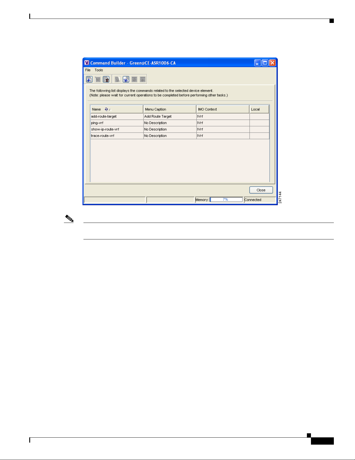
Chapter 6 IPv6 VPN over MPLS
Figure 6-5 Command Builder Route Target Commands
Provisioning Route Targets
Note To assign address families to VPN communities, the VRF must have been created with the vrf definition
Cisco IOS command. Address families cannot be assigned to VRFs created with the ip vrf command.
After you launch the Cisco ANA NetworkVision or Command Builder command, the Add Route Target
Import With Address Family or Add Route Target Export With Address Family dialog box appears
(Figure 6-6). The dialog box contains an Input tab and a Results tab. The Input tab is where you enter
the VPN community (either import or export), route target, and address family.
OL-19192-01
Cisco Active Network Abstraction 3.6.6 MPLS User Guide
6-9
Page 68
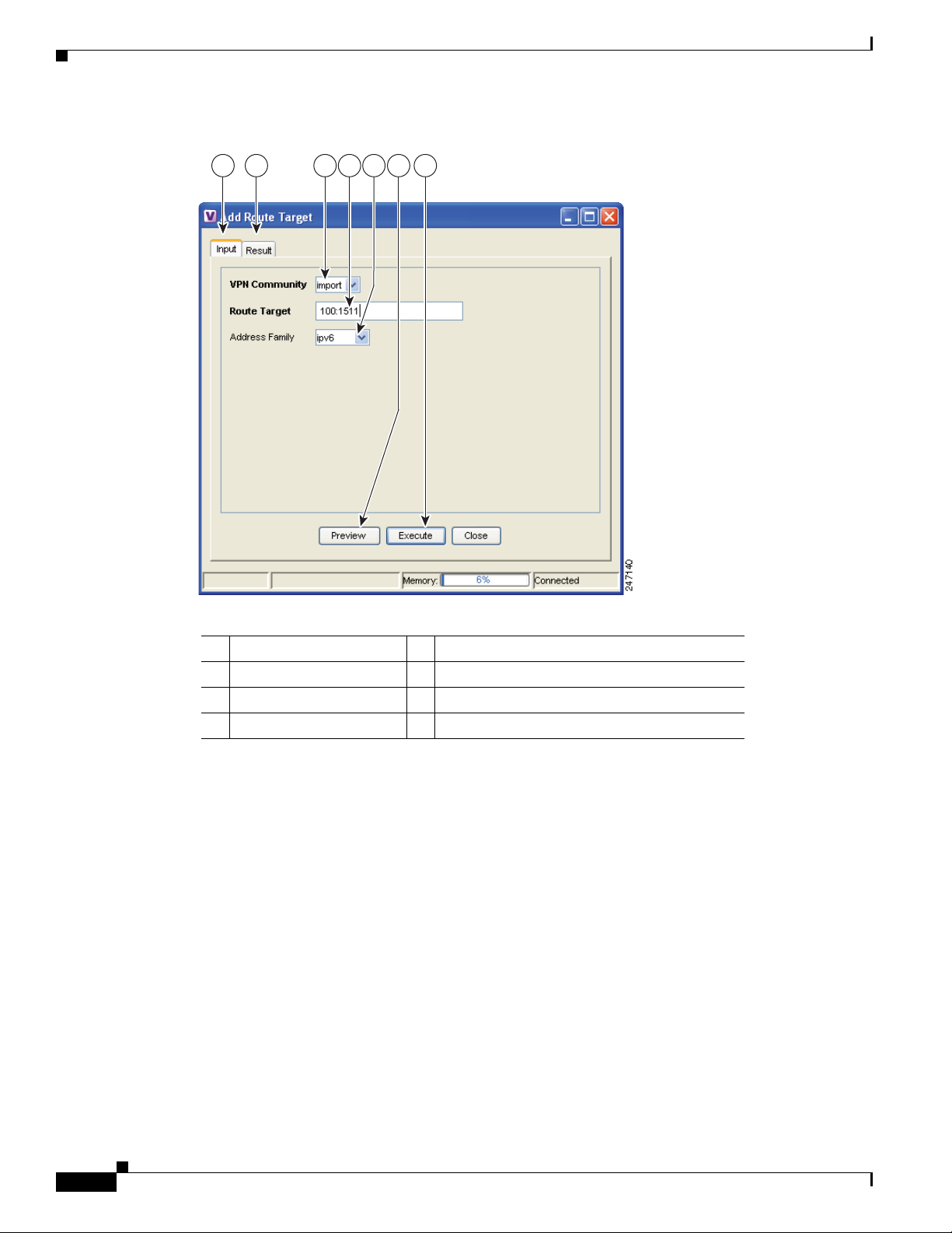
Provisioning Route Targets
1 2 3 4 5 6 7
Figure 6-6 Add Route Target Export with Address Family Dialog Box
Chapter 6 IPv6 VPN over MPLS
1 Input tab 2 Result tab
3 VPN Community field 4 Route Target field
5 Address Family field 6 Preview button
7 Execute button
You can click Preview to preview the command sequence in the Result tab (Figure 6-7).
6-10
Cisco Active Network Abstraction 3.6.6 MPLS User Guide
OL-19192-01
Page 69
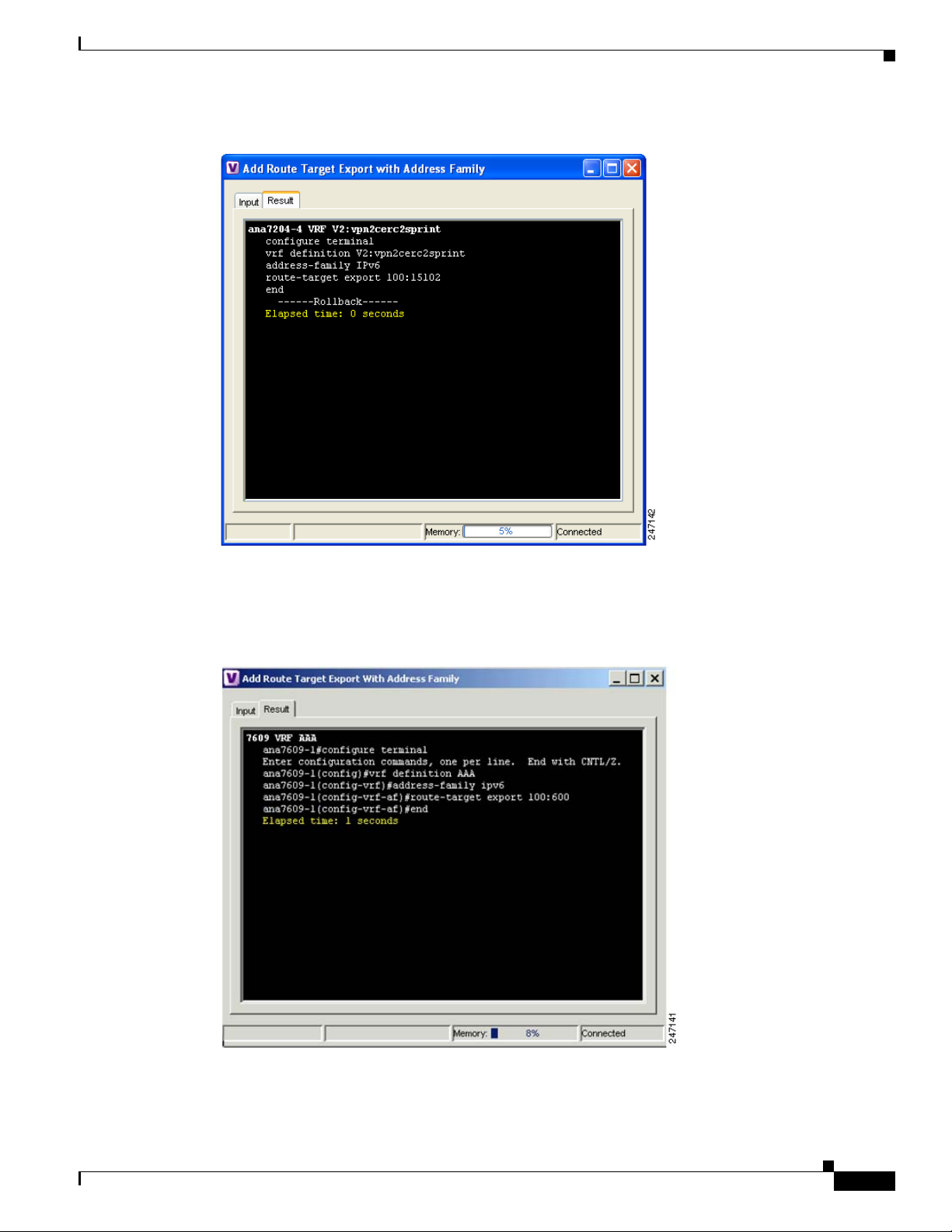
Chapter 6 IPv6 VPN over MPLS
Figure 6-7 Add Route Target Export with Address Family Preview
Provisioning Route Targets
After you execute the command on the device, you view the commands that were executed on the device
in the Result tab (Figure 6-8).
Figure 6-8 Execution Results for Add Route Target Export with Address Family
OL-19192-01
Cisco Active Network Abstraction 3.6.6 MPLS User Guide
6-11
Page 70

Provisioning Route Targets
Use the following procedures to enable IPv6 VRFs and add or delete route targets with IPv4 and IPv6
address families:
• Enabling IPv6 VRFs, page 6-12
• Adding Route Targets with IPv4 and IPv6 Address Families, page 6-12
• Deleting Route Targets with IPv4 and IPv6 Address Families, page 6-13
Enabling IPv6 VRFs
To configure a VRF with an IPv6 address family, IPv6 VRF must be enabled on the device. You can do
this in Cisco NetworkVision by completing the following steps:
Step 1 Display the Cisco NetworkVision inventory window.
Step 2 Right-click the ASR device where you want to enable the IPv6 VRF and choose Commands > VRF >
Enable IPv6 VRF.
The Enable IPv6 VRF command window appears.
Step 3 Click Preview to preview the command.
A preview of the command that will be executed appears in the Preview tab.
Chapter 6 IPv6 VPN over MPLS
Step 4 Click the Input tab, then click Execute.
The results are displayed in the Preview tab.
Step 5 Click Close.
Adding Route Targets with IPv4 and IPv6 Address Families
To add a route target with an IPv4 or IPv6 address family:
Step 1 In the Cisco ANA NetworkVision navigation tree, right-click the router containing the VRF to which
you want to assign a route target and choose Inventory.
Step 2 In the device inventory view, expand the Logical Inventory tree until you reach the VRF to which you
want to assign the route target with address family.
Step 3 Right-click the VRF and choose Commands > Add Route Target.
Step 4 In the Add Route Target dialog box Input tab, enter the following:
• VPN Community—Choose the VPN community to which you want to add the route target address
family, either Import or Export.
• Route Target—Enter the route target in the format ASN:nn or IP-address:nn, where ASN is the
associated system number and nn is the number assigned to the route target.
• Address Family—Enter the address family:
–
IPv4—Assigns an IPv4 address family to the route target.
6-12
–
IPv6—Assigns an IPv6 address family to the route target.
–
Not_Set—Adds a route target without an address family.
Cisco Active Network Abstraction 3.6.6 MPLS User Guide
OL-19192-01
Page 71

Chapter 6 IPv6 VPN over MPLS
Step 5 If you want to preview the route target, click Preview.
The Result tab displays the commands that will be executed on the device.
Step 6 Click Execute.
The Result tab displays the commands that were executed on the device.
Step 7 Click Close to close the window.
Deleting Route Targets with IPv4 and IPv6 Address Families
To remove a route target with an IPv4 or IPv6 address family from a device:
Step 1 In the Cisco ANA NetworkVision navigation tree, right-click a router containing the VRF with the route
target you want to remove and choose Inventory.
Step 2 In the device inventory view, expand the Logical Inventory tree until you find the VRF containing the
route target you want to remove.
Step 3 Click the VRF.
Provisioning Route Targets
The VRF properties appear in the Cisco ANA workspace.
Step 4 Right-click an import or an export route target and choose Configuration > Remove route target
(Figure 6-9).
Step 5 On the confirmation message box, click OK.
OL-19192-01
Cisco Active Network Abstraction 3.6.6 MPLS User Guide
6-13
Page 72
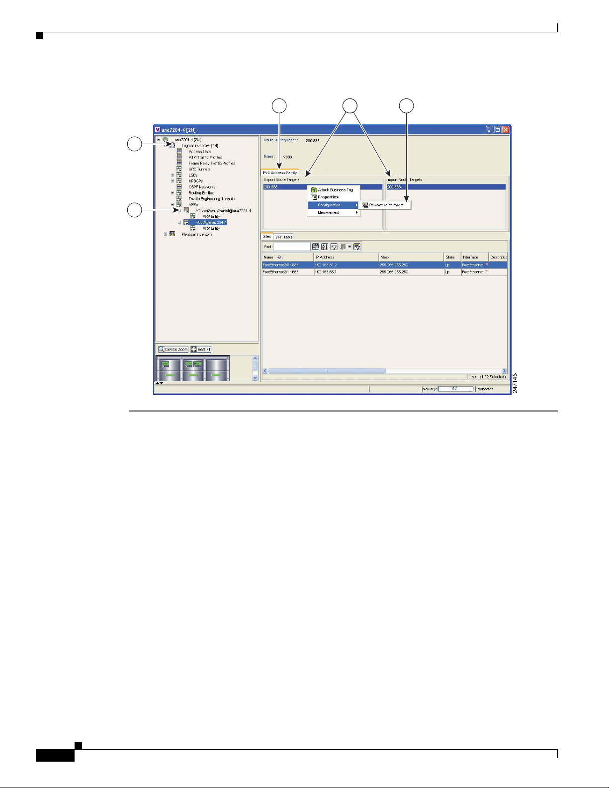
Provisioning Route Targets
1
2
3 54
Figure 6-9 Deleting Route Targets
Chapter 6 IPv6 VPN over MPLS
Cisco Active Network Abstraction 3.6.6 MPLS User Guide
6-14
OL-19192-01
Page 73

CHAP T ER
7
MPLS Network Faults
The following topics describe the alarms that Cisco ANA detects and reports for MPLS, LSP, LDP, BGP,
TE tunnels, and Layer 2 VPNs. Topics include:
• MPLS Network Alarms Overview, page 7-1—Provides a summary of the MPLS and VPN alarms
supported in Cisco ANA.
• BGP Neighbor Loss Alarm, page 7-2—Describes the BGP Neighbor Loss alarm.
• BGP Process Down Alarm, page 7-3—Describes the BGP Process Down alarm.
• Broken LSP Discovered Alarm, page 7-3—Describes the Broken LSP Discovered alarm.
• LDP Neighbor Down Alarm, page 7-4—Describes the LDP Neighbor Down alarm.
• MPLS Black Hole Found Alarm, page 7-5—Describes the MPLS Black Hole Found alarm.
• MPLS TE Tunnel Alarms, page 7-5—Describes the MPLS TE Tunnel Down, MPLS TE Tunnel
Flapping, and Tunnel Reoptimized alarms.
• Pseudo Wire MPLS Tunnel Down Alarm, page 7-6—Describes the Pseudo Wire (L2 VPN) MPLS
Tunnel Down alarm.
Note For a description of the Cisco ANA alarm ticket pane and a complete listing of all alarms supported by
Cisco ANA, see the Cisco Active Network Abstraction 3.6.6 User Guide.
MPLS Network Alarms Overview
Table 7-1 lists the MPLS, BGP, LSP, LDP, TE tunnel, and Layer 2 VPN alarms supported by Cisco ANA.
Alarms are displayed in the ticket pane of the Cisco ANA NetworkVision window.
OL-19192-01
Cisco Active Network Abstraction 3.6.6 MPLS User Guide
7-1
Page 74

BGP Neighbor Loss Alarm
Table 7-1 MPLS Network Alarms Supported by Cisco ANA
Alarm Default Severity Description Up Alarm
BGP Neighbor
Loss
Broken LSP
Discovered
LDP Neighbor
Down
MPLS Black
Hole Found
MPLS TE Tunnel
Down
MPLS TE Tunnel
Flapping
Pseudo Wire (L2
VPN) MPLS
Tunnel Down
Tunnel
Reoptimized
Chapter 7 MPLS Network Faults
Red (critical) Generated whenever BGP connectivity is
lost to a specific device.
Orange (major) Activates a backward flow on the untagged
entry to traverse the full LSP path passing
through it. The alarm is generated whenever
Cisco ANA locates services (such as VRFs
and pseudowires) on the path that use the
LSPs.
Orange (major) Generated whenever a TCP connection
failure occurs in LDP path, or the interface
no longer runs MPLS.
Dark blue
(information)
Orange (major) Generated whenever a TE tunnel’s
Orange (major) Generated whenever multiple up and down
Yellow (minor) Generated whenever the pseudowire link
Dark Blue
(information)
Generated whenever Cisco ANA discovers
an MPLS interface that has at least one
untagged LSP leading to a known PE router.
operational status changes to down and the
tunnel is not flapping.
alarms are generated during a short time
interval and they are suppressed.
goes down, namely, the pseudowire is
reported as down from both the devices
(based on the status of the tunnel).
Generated from a syslog message sent by
the router whenever a tunnel is up and its
route changes but the tunnel continues to
remain up.
BGP Neighbor
Found
N/A
LDP Neighbor Up
MPLS Black Hole
Cleared
MPLS TE Tunnel
Up
MPLS TE Tunnel
Up or MPLS TE
Tunnel Down
Layer 2 Tunnel Up
N/A
BGP Neighbor Loss Alarm
If BGP connectivity is lost to a specific device in an MPLS VPN network, VPN sites lose connectivity.
The VNE models the BGP connection between routers and actively monitors its state. A BGP Neighbor
Loss alarm is generated from both sides of the connection when a connectivity loss occurs. Alarms and
tickets are issued and impact analysis information displayed.
The correlation engine identifies various faults that affect the BGP connection and reports them as the
root cause for the BGP neighbor loss alarm, for example, Link Down, CPU Overutilized, and Link Data
Loss.
Note BGP Neighbor Loss alarms are not correlated to each other. They are correlated to the root cause of the
connectivity loss.
Cisco Active Network Abstraction 3.6.6 MPLS User Guide
7-2
OL-19192-01
Page 75

Chapter 7 MPLS Network Faults
The BGP Neighbor Loss alarm is detected actively by the system and service alarms are generated. The
system also supports BGP neighbor down syslogs.
When the VNE BGP component polls the BGP neighbor status (expedite or normal polling) and finds
an entry for a neighbor no longer exists or its state changed from Established to another state, the BGP
component issues a BGP Neighbor Loss alarm. This alarm causes the BGP component to issue a Root
Cause Analysis (RCA) correlation flow to find the root cause. If RCA does not find an alarm to correlate,
the VNE sends the alarm to the gateway as a ticket.
If this alarm is configured in the registry to issue a Look For Affected flow. If a BGP neighbor loss occurs
and the BGP component has no other BGP PE links, all VRFs with route entries to the PE as BGP next
hops are true-affected. This information is sent as an update to the previous BGP Neighbor Loss alarm.
BGP Process Down Alarm
A Cisco ANA query checks the status of the BGP process when the VNE BGP component polls for the
status and configuration of its BGP neighbors (expedite or normal polling). If the BGP process is not
running, the VNE BGP component issues an BGP Process Down alarm. This alarm is always a ticket and
does not try to correlate to other alarms. All the BGP Neighbors Down alarms issued in response to the
BGP Process Down alarm and is correlated to the BGP Process Down ticket.
BGP Process Down Alarm
Broken LSP Discovered Alarm
The MPLS Black Hole Found alarm activates a backward flow on the specific untagged entry in order
to traverse the full path of the LSPs passing through it. If Cisco ANA locates services (for example,
VRFs, pseudowire tunnels) along this path that are using these LSPs, a Broken LSP Discovered alarm is
issued. Such services can be found only on PE routers, and they can be found on more than one PE router.
The source of the Broken LSP Discovered alarm is the PE router on which the service was discovered,
and in many cases this router is different from the router that issued the MPLS Black Hole Found alarm.
Broken LSP Discovered alarms are correlated to the MPLS Black Hole Found alarm (except in the case
of a black hole alarm due to a link down). The Broken LSP Discovered alarm is detected actively by the
system, namely, service alarms are generated. An example of an MPLS black hole scenario follows.
In the network described in this example, the shortest path from PE2 to PE3 is PE2<->P2<->PE3. The
link between P2 and PE3 is an MPLS link, meaning interfaces on both sides of the link are configured
as MPLS interfaces. Also assume that for some reason, the MPLS configuration is incomplete or
incorrect, namely:
• Only one interface is configured as an MPLS interface.
• The label distribution protocol is configured differently on both interfaces (protocol mismatch).
In this case, the label switching table on P2 and PE3 will have untagged entries for the LSPs between
PE2 and PE3. If PE2 and PE3 have VPN services (for example VRFs and pseudowires), the outcome
will be that the data flow between PE2 and PE3 will be affected.
OL-19192-01
Cisco Active Network Abstraction 3.6.6 MPLS User Guide
7-3
Page 76

LDP Neighbor Down Alarm
Provider network
P2
PE2
PE3
VPN1
VPN3
VPN1
VPN3
154563
Figure 7-1 Example of an MPLS Black Hole Scenario
In this case, Cisco ANA does the following:
• Identifies untagged label switching entries on P2 and PE3.
• Issues MPLS Black Hole Found alarms on the interfaces on both sides of the link (since the LSP is
• Initiates a backward flow starting from the link on the specific untagged entries and identifies the
unidirectional).
two LSPs traversing the link, namely:
–
LSP from PE2 to PE3
–
LSP from PE3 to PE2
Chapter 7 MPLS Network Faults
• Issues Broken LSP Discovered alarms on both LSPs in PE2 and PE3, which are correlated to the
corresponding MPLS Black Hole Found alarm.
Note The clearing alarm does not activate flows to locate the LSPs that were passing through it in order to
issue a clearing alarm for Broken LSPs, but rather uses the auto-clear functionality. The gateway
periodically reviews the tickets and checks if all the alarms under each ticket are cleared or configured
as auto-cleared alarms, and whether the gateway correlation timeout has passed, in which case the
gateway closes the ticket.
After the MPLS Black Hole alarm clears, and the configured gateway correlation timeout period is
reached, the gateway can close the ticket because all the alarms correlated to MPLS Black Hole and
Broken LSP are auto-cleared.
Note If an MPLS Network Link Down event causes an IP reroute and an LDP redistribution, new LSPs might
be redirected through non-MPLS segments, which will create a black hole. In this case, Broken LSP
Discovered alarms are issued. However, the discovered broken LSPs are correlated to the Link Down
alarm and not to the MPLS Black Hole Found alarm.
LDP Neighbor Down Alarm
7-4
LDP enables neighboring P or PE routers acting as LSRs to discover peers in an MPLS network to which
they can establish LDP sessions. The sessions allow the routers to negotiate and exchange labels used
for forwarding packets.
Cisco Active Network Abstraction 3.6.6 MPLS User Guide
OL-19192-01
Page 77

Chapter 7 MPLS Network Faults
If a session to an LDP neighbor goes down, an LDP Neighbor Down alarm is issued. This can happen as
the result of a failure in the TCP connection used by the LDP session, or if the interface is no longer
running MPLS. The LDP neighbor down alarm is cleared by a corresponding LDP Neighbor Up alarm.
The alarm is issued when a peer is removed from the table in the LDP Neighbors tab. The alarm runs a
correlation flow to detect the network core triggering event A root cause analysis is performed to find
the root cause. The alarm initiates an IP-based flow toward the peer transport address destination. If an
alarm is found during the flow, that alarm is correlate to to the LDP Neighbor Down alarm.
Note The LDP Neighbor Down alarm can correlate to the MPLS Interface Removed alarm.
MPLS Black Hole Found Alarm
an MPLS black hole is defined as an abnormal termination of an MPLS path (LSP) inside an MPLS
network. An MPLS black hole exists when on a specific interface there are untagged entries destined for
a known PE router. It is assumed that a router functions as a PE router if there are services using the
MPLS network, such as L3 VPNs or pseudowire (L2 VPN) MPLS tunnels. Note that the untagged
interfaces may exist in the network in normal situations. For example, where the boundary of the MPLS
cloud has untagged interfaces this is still considered normal.
An MPLS black hole cause the loss of all the MPLS labels on a packet including the VPN information
that lies in the inner MPLS label. If a packet goes through an untagged interface, the VPN information
is lost. The VPN information loss causes VPN sites to lose connectivity.
MPLS Black Hole Found alarms are actively detected. Service alarms are generated whenever
Cisco ANA discovers an MPLS interface with at least one untagged LSP leading to a known PE router.
MPLS Black Hole Found Alarm
Black hole alarms are detected either:
• When the system is loaded for the first time and performs the initial discovery of the network.
• Through the ongoing discovery process, which identifies changes in the network.
Note The MPLS black hole discovery is supported only when the PEs are managed by Cisco ANA.
MPLS TE Tunnel Alarms
MPLS TE tunnel alarms include:
• MPLS TE Tunnel Down
• MPLS TE Tunnel Flapping
• Tunnel Reoptimized
If a TE tunnel operational status changes to down, an MPLS TE Tunnel Down alarm is generated. The
Cisco ANA correlation engine identifies the faults that affect the TE tunnel status and identifies the root
cause for the MPLS TE Tunnel Down alarm. For example, a Link Down will cause a TE tunnel to go
down. Multiple up and down alarms that are generated during a short time interval are suppressed and
displayed as an MPLS TE Tunnel Flapping alarm (according to the specific flapping configuration).
MPLS TE Tunnel Down and MPLS TE Tunnel Flapping alarms are actively detected and service alarms
are generated. The system also supports MPLS TE Tunnel Down syslogs, which are correlated to the
service alarm.
OL-19192-01
Cisco Active Network Abstraction 3.6.6 MPLS User Guide
7-5
Page 78

Pseudo Wire MPLS Tunnel Down Alarm
For Cisco CRS-1 routers running Cisco IOS XR 3.6 software and using PBTS in MPLS or MPLS VPN
networks, Cisco ANA supports the following ubalarms for the MPLE TE Tunnel Down alarm:
• High Priority MPLS TE Tunnel Down
• Medium Priority MPLS TE Tunnel Down
• Low Priority MPLS TE Tunnel Down
The specific subalarm that is generated depends on the EXP bit specified for the traffic. Cisco ANA maps
the specified EXP bit to tunnel priority and uses that mapping to generate the resultant subalarm. The
alarm description includes information about the EXP bit.
Tunnel reoptimization occurs when a tunnel is up and its route changes but the tunnel continues to
remain up. When a TE tunnel is reoptimized to take a different path, the system parses the tunnel
reoptimized syslog, if such a syslog is available, and displays it as a ticket.
The Tunnel Reoptimized alarm is generated from a syslog message sent by the router.
Pseudo Wire MPLS Tunnel Down Alarm
A Pseudo Wire MPLS Tunnel Down alarm is issued when the pseudowire link goes down, namely, the
pseudowire tunnel is reported as down from both the devices (based on the status of the tunnel), and the
tunnel is not flapping.
Chapter 7 MPLS Network Faults
The correlation engine identifies various faults that affect the pseudowire tunnel status and reports on
them as the root cause for the Pseudo Wire MPLS Tunnel Down alarm, for example, Link Down.
Cisco ANA traces the LSE path to the edge of the PWE3 tunnel and marks the edges of the tunnel as
affected. The Pseudo Wire MPLS Tunnel Down alarm is detected actively by the system, namely, service
alarms are generated.
7-6
Cisco Active Network Abstraction 3.6.6 MPLS User Guide
OL-19192-01
Page 79

Impact Analysis in MPLS Networks
The following topics provide an overview of the service impact analysis solution and supported
scenarios, which are used in VPN networks that are based on MPLS, including Layer 3 and Layer 2
VPNs. In addition, theybriefly describes proactive and automatic impact analysis.
• Service Impact Analysis Overview, page 8-1—Describes the service impact analysis solution.
• Service Impact Analysis For MPLS-Based VPN Services, page 8-2—Describes the impact analysis
process for Layer 3 VPN and pseudowire (Layer 2 VPN) scenarios.
• Supported Fault Scenarios, page 8-3—Describes the scenarios supported by the service impact
analysis solution.
Service Impact Analysis Overview
Cisco ANA analyzes network faults to identify the NEs involved in the VPN services (such as interfaces
on the PE) that are affected, or potentially affected, by the fault. After a fault occurs, Cisco ANA
automatically generates the list of potential and actual service resources affected by a fault and embeds
this information in the ticket along with all the correlated faults. (You can configure this behavior.)
CHAP T ER
8
OL-19192-01
Note Automatic impact analysis is not performed for every service alarm. It is performed for a small group of
selected alarms, for example, BGP Neighbor Loss, Broken LSP, Link Down, Layer 2 Tunnel Down, and
so on.
During Cisco ANA impact analysis, affected parties can be marked with one of the following severities:
• Potentially Affected—The service might be affected but its real state is unknown.
• Real Affected—The service is affected.
• Recovered—The service has recovered. This state applies only to entries that were previously
marked as potentially affected. It indicates only that there is an alternate route to the service,
regardless of the service quality level)
The initial impact report may mark the services as either Potentially Affected or Real Affected. As time
progresses and more network information is accumulated, the system might issue an additional report to
indicate which of the potentially affected parties are Real Affected or Recovered. These indications are
available through the API and the Cisco ANA GUI.
Cisco Active Network Abstraction 3.6.6 MPLS User Guide
8-1
Page 80

Service Impact Analysis For MPLS-Based VPN Services
Note The reported impact severities vary between fault scenarios. For more information about specific support
for each fault scenario, see Supported Fault Scenarios, page 8-3.
Note After the alarm clears, no Clear state for the affected services is generated. However, you can verify that
the alarm cleared by checking the Alarm Clear State column in the Affected Parties tab of the Ticket
Properties window. For more information about the Affected Parties tab of the Ticket Properties window,
see the Cisco Active Network Abstraction 3.6.6 User Guide.
Cisco ANA provides “what-if” scenarios for determining the possible effect of network failures. This
enables on-demand calculation of affected VPN sites for physical links in the network, thus enabling an
immediate service availability check and analysis for potential impact and identification of critical
network links. After executing a what-if scenario, Cisco ANA initiates an end-to-end flow to identify all
the potentially affected edges in the affected VPNs. Proactive impact analysis is available from the
following:
• Link Properties dialog box when selecting a physical link.
• Topological Link Properties window when selecting a physical link in the links view.
Chapter 8 Impact Analysis in MPLS Networks
For more information about proactive impact analysis, see the Cisco Active Network Abstraction 3.6.6
User Guide.
Service Impact Analysis For MPLS-Based VPN Services
An MPLS network with PE routers is supported, where the PE routers implement either of the following:
• Layer 3 VPN (VRFs are affected)
• Pseudowire (L2 VPN tunnels are affected)
These scenarios are described in the following topics:
• L3 VPN Report, page 8-2
• Pseudowire (L2 VPN) Report, page 8-3
Note Descriptions provided in these scenarios refer only to faults in the MPLS core and not to faults in access
networks.
L3 VPN Report
When the Cisco ANA impact analysis identifies the affected parties, the VRFs are displayed as the
affected parties on the PE routers that lost connectivity between them in the Ticket Properties window.
The number of affected parties that are reported is calculated from the pairs of VRFs and are reported in
the Ticket Properties window. The structure of the edge point ID is Device ID \VRF ID\Subinterface (or
interface) ID. (The subinterface or interface ID is optional.)
8-2
Note VRF sites are not reported as affected pairs.
Cisco Active Network Abstraction 3.6.6 MPLS User Guide
OL-19192-01
Page 81

Chapter 8 Impact Analysis in MPLS Networks
Figure 8-1 shows an example with two PEs, A and B, and a VRF in the same VPN. The Layer 3 VPN
faults that are reported are AX – BX.
Figure 8-1 Layer 3 VPN Example
Pseudowire (L2 VPN) Report
When a pseudowire tunnel goes down and an alarm occurs, the affected service resources are calculated
by tracing the LSP to the edge of the pseudowire tunnel and collecting the affected pairs from both sides
of the pseudowire tunnel. The edges of the tunnel are marked as affected.
The affected pairs are displayed in the Ticket Properties window. For more information about the Ticket
Properties window, see the Cisco Active Network Abstraction 3.6.6 User Guide.
Supported Fault Scenarios
Supported Fault Scenarios
The following fault scenarios trigger automatic impact analysis calculation:
• Link Down Scenario, page 8-4
• Link Overutilized/Data Loss Scenario, page 8-4
• BGP Neighbor Loss Scenario, page 8-5
• Broken LSP Discovered Scenario, page 8-7
• MPLS TE Tunnel Down Scenario, page 8-7
• Pseudowire MPLS Tunnel Down Scenario, page 8-7
The following criteria are used in the tables that are described in the sections that follow:
• Impact Calculation—Describes the way in which the affected parties are calculated by system flows.
• Reported Affected Severity—Describes the kind of severity generated by the alarm.
Note Proactive impact analysis is performed only for links.
OL-19192-01
Cisco Active Network Abstraction 3.6.6 MPLS User Guide
8-3
Page 82

Supported Fault Scenarios
Link Down Scenario
Table 8-1 shows the impact calculations and reported affected severities for a link down fault scenario.
Table 8-1 Link Down Scenario
Impact and Affected Severity Description
Impact calculation Initiates an affected flow to determine the affected parties using the
Reported affected severity
Chapter 8 Impact Analysis in MPLS Networks
LSPs traversing the link.
• The Link Down alarm creates a series of affected severity updates
over time. These updates are added to the previous updates in the
system database. In this case, the system provides the following
reports:
–
The first link down report shows “X<->Y” as Potentially
Affected.
–
Over time, the VNE identifies that this service is Real
Affected or Recovered and generates an updated report (this
applies only to cross-MPLS networks).
This functionality is currently supported for Link Down only.
Link Overutilized/Data Loss Scenario
Table 8-2 shows the impacted calculations and reported affected severities for a link overutilized/data
loss fault scenario.
Table 8-2 Link Overutilized/Data Loss Scenario
Impact and Affected Severity Description
Impact calculation Initiates an affected flow to determine the affected parties using the
LSPs traversing the link.
Reported affected severity Only reports on potentially affected.
–
The Affected Parties tab of the Ticket Properties dialog box
displays the latest severity, for example, Real Affected.
–
The Affected Parties Destination Properties dialog box
displays both reported severities.
8-4
Cisco Active Network Abstraction 3.6.6 MPLS User Guide
OL-19192-01
Page 83

Chapter 8 Impact Analysis in MPLS Networks
BGP Neighbor Loss Scenario
Table 8-3 shows the impacted calculations and reported affected severities for a BGP neighbor loss fault
scenario.
Table 8-3 BGP Neighbor Loss Scenario
Impact and Affected Severity Description
Impact calculation
Reported affected severity Only reports on Real Affected on the IBGP domain.
Supported Fault Scenarios
• Initiates a local affected flow to all VRFs that are present on the
issuing device. Each local VRF that has route entries with a next
hop IP that was learned from the BGP neighbor that was lost
collects VRFs from both sides and pairs them together as
affected.
• Supports a route reflector configuration, whereby during the
affected search, affected parties are located on all BGP neighbors
learned via the route reflector.
Note The BGP Neighbor Loss alarm represents a scenario where there is a BGP neighbor down.
Note The affected only relate to L3 VPN services.
BGP rules require all routers within an autonomous system be fully meshed. For large networks, this
requirement represents a severe scaling problem. Route reflectors enable a BGP entity to establish a
single BGP connection with a peer, where through that single peer, routing information is learned from
other peers. As a result, the number of BGP sessions and connections is greatly reduced.
Decreasing the number of BGP connections and the presence of route reflectors further separates the
data and control paths. For example, data packets going from A to B do not go through the route reflector
while the routing updates between A and B do.
Every BGP router is uniquely identified by a router ID. A route reflector is not a configuration of a
specific router. A router may act as a route reflector if it has a BGP neighbor configured as a BGP client.
A router may act as both a route reflector to some of its BGP neighbors (those that are configured as
BGP clients) and a non-client BGP neighbor to those BGP neighbors that are configured as non-client
BGP neighbors.
A route reflector follows the following logic when distributing routes to its BGP neighbors:
• A router advertises to its client peers all routes learned from both other client and non-client peers.
• A router advertises to its non-client peers only routes received from client peers.
Router ID distribution follows the same logic described previously here.
OL-19192-01
Cisco ANA modeling provides a list of one or more router IDs for each interface. This reflects the
network behavior of receiving BGP updates from a BGP router (possessing that ID) through that
interface. The VNE also maintains the nature of the relationships (client and non-client) among the
various VNEs representing the BGP routers. Figure 8-2 shows an example.
Cisco Active Network Abstraction 3.6.6 MPLS User Guide
8-5
Page 84

Supported Fault Scenarios
IF 1
IF 1
IF 1
IF 1
IF 3
IF 2
IF 2
IF 2
Router A
(RR)
Router BRouter D
Router C
154564
Figure 8-2 Route Reflector Example
In the example, the following configuration is applied:
• Router A (router ID A) has clients configured B, C, and D. Therefore it serves as the route reflector
• Routers B, C, and D all have Router A as a BGP non-client neighbor.
Chapter 8 Impact Analysis in MPLS Networks
for these BGP routers.
• Router D and Router B also have each other configured as BGP non-client neighbors.
In this case, in Cisco ANA, the following information is maintained by a VNE:
• Router B learns router ID D from interface 1.
• Router B learns router IDs A, C, and D from interface 2.
• Router C learns router IDs A, B, and D from interface 1.
• Router D learns router ID B from interface 2.
• Router D learns router IDs A, B, and C) from interface 1.
• Router A learns router ID D from interface 1.
• Router A learns router ID C from interface 2.
• Router A learns router ID B from interface 3.
In the Figure 8-2 example, if a BGP connection is lost from Router A to Router B, the following occurs:
• Router A notifies both Routers C and D of the loss of router ID B.
• Router C removes the ID of Router B from its tables and completely loses connectivity to it,
resulting in a Real Affected impact analysis.
• Router D loses the ID of Router B learned from interface 1, but it still has Router B’s ID that was
learned through interface 2. Therefore, no impact analysis is performed.
If a BGP connection is lost from Router B to Router D, the following occurs:
• Router B does not notify Router A of its router ID loss, because Router A is configured in Router
B’s tables as a non-client peer.
• Router D does not notify Router A of its router ID loss, because Router A is configured in Router
D’s tables as a non-client peer.
• Router B notes that the ID of Router D is no longer learned through interface 1.
8-6
Cisco Active Network Abstraction 3.6.6 MPLS User Guide
OL-19192-01
Page 85

Chapter 8 Impact Analysis in MPLS Networks
• Router D notes that the ID of Router B is no longer learned through interface 2.
• No impact analysis is performed.
Broken LSP Discovered Scenario
Table 8-4 shows the impacted calculations and reported affected severities for a broken LSP discovered
fault scenario.
Table 8-4 Broken LSP Discovered Scenario
Impact and Affected Severity Description
Impact calculation Initiates an affected flow to determine all the affected parties using
Reported affected severity Only reports on Real Affected. When the Link Down is cleared, all
Supported Fault Scenarios
the LSP.
the correlated broken LSP alarms are auto-cleared.
MPLS TE Tunnel Down Scenario
Table 8-5 shows the impacted calculations and reported affected severities for an MPLS TE tunnel down
fault scenario.
Table 8-5 MPLS TE Tunnel Down Scenario
Impact and Affected Severity Description
Impact calculation Initiates a flow to look for affected parties.
Reported affected severity Only reports on real affected.
Pseudowire MPLS Tunnel Down Scenario
Table 8-6 shows the impacted calculations and reported affected severities for a pseudowire MPLS
tunnel down fault scenario.
Table 8-6 Pseudowire MPLS Tunnel Down
Impact and Affected Severity Description
Impact calculation Initiates a flow to look for the affected parties.
Reported affected severity Only reports on real affected on the MPLS domain.
OL-19192-01
Cisco Active Network Abstraction 3.6.6 MPLS User Guide
8-7
Page 86

Supported Fault Scenarios
Chapter 8 Impact Analysis in MPLS Networks
8-8
Cisco Active Network Abstraction 3.6.6 MPLS User Guide
OL-19192-01
Page 87

CHAP T ER
9
Using Cisco ANA PathTracer in MPLS Networks
The following topics describe how you can use the Cisco ANA PathTracer for Layer 2 and Layer 3
VPNs, and for MPLS TE tunnels:
• Cisco ANA PathTracer Tracing Capability, page 9-1—Provides a brief description of Cisco ANA
PathTracer.
• Using Cisco ANA PathTracer in MPLS Networks, page 9-2—Tells you how to use Cisco ANA
PathTracer.
• Cisco ANA PathTracer Windows, page 9-3—Describes the Cisco ANA PathTracer multipath and
single-path windows working environment and the information that can be viewed.
• Using Cisco ANA PathTracer for Layer 3 VPN, page 9-6—Tells you how to use the Cisco ANA
PathTracer for Layer 3 VPNs, including opening the Cisco ANA PathTracer and viewing path
information.
• Using Cisco ANA PathTracer for Layer 2 VPN, page 9-6—Tells you how to use the Cisco ANA
PathTracer for Layer 2 VPNs, including opening the Cisco ANA PathTracer and viewing path
information.
• Using Cisco ANA PathTracer for MPLS TE Tunnels, page 9-7—Tells you how to use the
Cisco ANA PathTracer for MPLS TE tunnels, including opening the Cisco ANA PathTracer and
viewing path information.
For more information about the Cisco ANA PathTracer, see the Cisco Active Network Abstraction 3.6.6
User Guide.
Cisco ANA PathTracer Tracing Capability
Cisco ANA PathTracer traces service routes or network connectivity between two points in the network
(or from a single starting point to an IP address) providing performance information simultaneously for
multiple networking layers along single as well as multiple routes. End-to-end paths are provided across
technologies and at different layers of the Open Systems Interconnection (OSI) stack. It also displays
various traffic and error statistics for each link and for each hop, helping to pinpoint problems that may
affect the service or cause service degradation.
Cisco ANA PathTracer identifies the location of the service-affecting problems (for example, devices,
slots, ports, and protocol stacks, including comprehensive multilayer status information with relevant
configuration and traffic parameters). Cisco ANA understands and is able to display the various services
on the network due to the up-to-date knowledge of the network.
OL-19192-01
Cisco Active Network Abstraction 3.6.6 MPLS User Guide
9-1
Page 88

Chapter 9 Using Cisco ANA PathTracer in MPLS Networks
Using Cisco ANA PathTracer in MPLS Networks
Cisco ANA PathTracer enables you to view multiple paths between the source and the destination (or
from a source to number of destinations) in the Cisco ANA PathTracer multipath window, or to view a
selected single path in the Cisco ANA PathTracer single-path window:
• Cisco ANA PathTracer multipath window—Displays all the discovered paths available between the
selected source and destination, including devices and links.
• Cisco ANA PathTracer single-path window—Displays a single path available between the selected
source and destination, as well as the subscribers and properties.
Note For more information about Cisco ANA PathTracer single and multipath windows, see the Cisco Active
Network Abstraction 3.6.6 User Guide
Using Cisco ANA PathTracer in MPLS Networks
You can open and view Cisco ANA PathTracer information between service endpoints, for example, the
IP interface that is attached to the VRF over an MPLS network. The LSP in the MPLS network is found
according to the cross-connect table of each router.
Note The LSP can be traced and displayed by Cisco ANA PathTracer as part of an end-to-end tracing of a
service as well; for example, when viewing a path between one CE device to another. Cisco ANA
PathTracer traces the path that goes over circuits or VLANs in the access networks. It also traces the
LSPs between the VRFs going through all intermediate devices such as CE devices, aggregation
switches, PE routers, and core routers.
To view a specific path, you must specify an initial starting point, such as an IP interface and a
destination IP address (optional). If the traced circuit (for example, a VC or VLAN) ends in a router,
Cisco ANA PathTracer finds the next hop according to the destination IP address. When you select an
endpoint, Cisco ANA extracts the relevant IP address from this point and uses it as the destination.
Cisco ANA PathTracer Starting Points
You can also open Cisco ANA PathTracer by right-clicking a starting point and entering the required
destination IP address. Tab l e 9-1 lists the Cisco ANA PathTracer starting points.
Table 9-1 Cisco ANA PathTracer Starting Points
Element Location Start Options
IP Interface
Site Service view map.
• Inventory window.
• Affected entity (enabled only if the
affected entity has an IP interface).
• To IP Destination
• Start Here
• To IP Destination
• To Subnet Destination
• Start Here
9-2
Cisco Active Network Abstraction 3.6.6 MPLS User Guide
OL-19192-01
Page 89

Chapter 9 Using Cisco ANA PathTracer in MPLS Networks
Table 9-1 Cisco ANA PathTracer Starting Points (continued)
Element Location Start Options
Business tag
attached to the
VPI/VCI or IP
interface
Layer 2 MPLS
Tunnel
LCP Service view map.
The path can be found using a business tag,
which is attached to the VPI/VCI or IP
interface by entering its key. It can then be
opened from the Find Business Tag window.
Inventory window. To IP Destination
Cisco ANA PathTracer Endpoints
If you choose the Start Here option, Table 9-2 lists the endpoints that can be selected as a path
destinations.
Cisco ANA PathTracer Windows
To IP Destination
• To IP Destination
• Start Here
Table 9-2 Cisco ANA PathTracer Endpoints
Element Location End Options
IP Interface
Site Service view map End Here
LCP Service view map End Here
The Cisco ANA PathTracer multipath window is displayed. From this window you can open the
Cisco ANA PathTracer single-path window with the appropriate VPN information displayed in the
Layer 2 and Layer 3 tabs.
Note If multiple paths are selected in the paths pane, or if nothing is selected in the paths pane, then all the
available paths are opened automatically, and each one are displayed in a separate Cisco ANA
PathTracer single-path window.
• Inventory window
• Affected entity (enabled only if the
affected entity has an IP interface)
Cisco ANA PathTracer Windows
The Cisco ANA PathTracer multipath window (Figure 9-1) displays all the discovered paths between the
selected source and destination for the selected context, including devices, links, and paths. The
Cisco ANA PathTracer multipath window enables you to do the following:
• View a previous path or the next path.
• Open the Cisco ANA PathTracer single-path window to view a single selected path.
End Here
OL-19192-01
• Save the multipath map to a file.
• Run the Cisco ANA PathTracer again.
Cisco Active Network Abstraction 3.6.6 MPLS User Guide
9-3
Page 90

Cisco ANA PathTracer Windows
Figure 9-1 Cisco ANA PathTracer Multipath Window
Chapter 9 Using Cisco ANA PathTracer in MPLS Networks
1 Menu bar 2 Toolbar
3 Map path traced at... tabs 4 Map pane
5 Status bar 6 Paths pane
The Cisco ANA PathTracer single-path window (Figure 9-2) displays the discovered-path devices and
links, as well as path layer properties. The Cisco ANA PathTracer single-path window enables you to:
• View a map of the intermediate network elements.
• View the following information for each network element:
–
The relevant parameters for each interface on all layers along the path.
–
For each layer, an indication of a mismatch between the parameters of the interfaces on both
sides of a link.
–
Traffic statistics along the path.
• Monitor the status and traffic of all the links along the path.
• View In and Out port properties.
In addition, right-clicking an item in Cisco ANA PathTracer enables you to view device properties and
attach business tags.
9-4
Cisco Active Network Abstraction 3.6.6 MPLS User Guide
OL-19192-01
Page 91
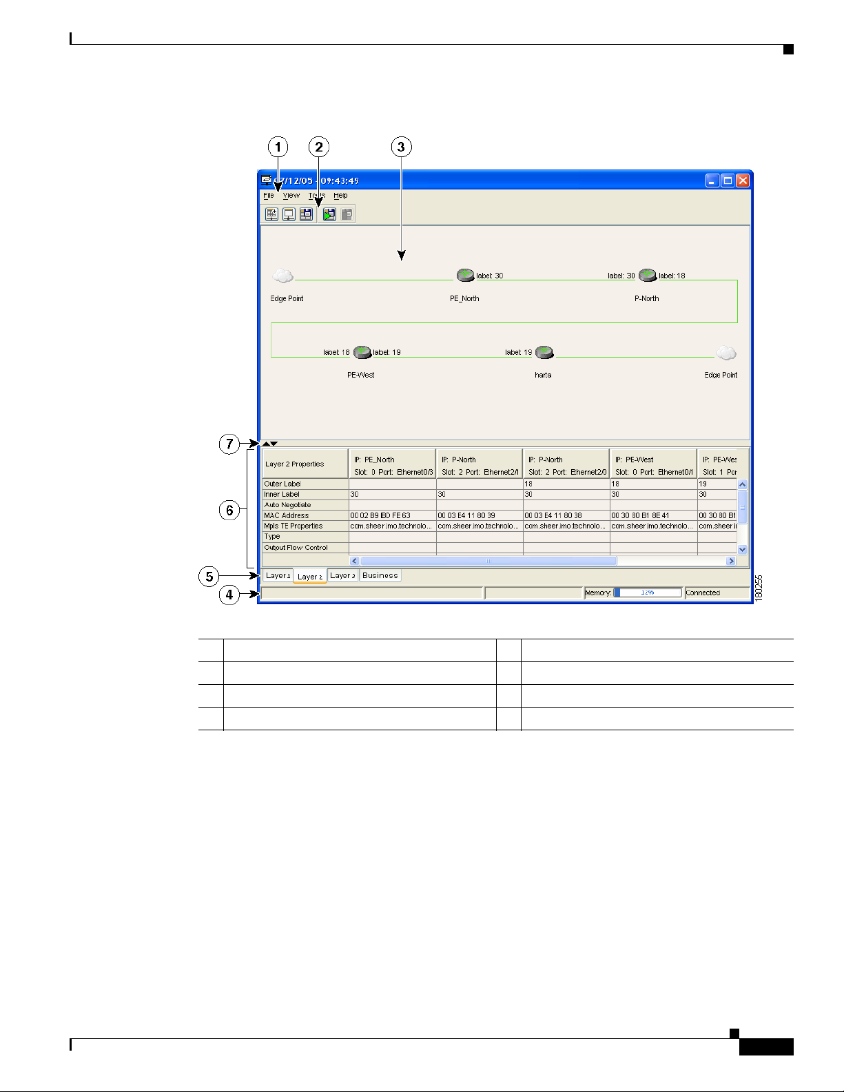
Chapter 9 Using Cisco ANA PathTracer in MPLS Networks
Figure 9-2 Cisco ANA PathTracer Single-Path Window
Cisco ANA PathTracer Windows
OL-19192-01
1 Menu bar 2 Toolbar
3 Map pane 4 Status bar
5 Layer tabs 6 Properties table
7 Hide or display Properties table
The Cisco ANA PathTracer single-path window displays information regarding each device. The
information is either plain data that was extracted from the device or calculated data such as rates or
statistics. The information is displayed in the Layer 1, Layer 2, and Layer 3 tabs.
In addition, the Cisco ANA PathTracer tabs display information regarding VPNs. The information is
displayed in the Layer 2 and Layer 3 tabs.
Cisco Active Network Abstraction 3.6.6 MPLS User Guide
9-5
Page 92

Chapter 9 Using Cisco ANA PathTracer in MPLS Networks
Using Cisco ANA PathTracer for Layer 3 VPN
Using Cisco ANA PathTracer for Layer 3 VPN
Cisco ANA Path Tracer uses VRF routing and label switching information to trace the path from one
VRF interface to another. If you choose a start and endpoint from the right-click menu, you can open the
Cisco ANA PathTracer for Layer 3 VPNs. The Cisco ANA PathTracer multipath window shows the VPN
topology map. From this window, you can open the Cisco ANA PathTracer single-path window with the
appropriate VPN information displayed in the Layer 2 and Layer 3 tabs.
For Layer 3 path information, Cisco ANA uses VRF routing and label switching information to trace the
path from one VRF interface to another. Layer 3 Cisco ANA PathTracer information is displayed in the
Cisco ANA PathTracer window when the path goes over connections and ends in VRFs.
To view Layer 3 path information, choose the Layer 3 tab and choose Show All from the View menu.
The path information is displayed in the active tab.
Note Selecting a device or link on the map automatically highlights the related parameters in the table.
The Cisco ANA PathTracer single-path window with the Layer 3 tab is displayed. The table displays the
Layer 3 VPN information on the device that has a VRF. The following Layer 3 properties displayed in
the Layer 3 tab relate specifically to VPNs:
• Name—The name of the site, for example, ATM4/0.100(10.0.0.1) is a combination of the interface
name and IP address used to reach the site. Each site belongs to a particular VPN, so the address
must be unique within the VPN.
• IP Address—The IP address of the interface.
• Mask—The mask of the specific network.
• State—The state of the interface (up or down).
• VRF Name—The name of the VRF.
• Sending Alarms—Whether the alarm for the required port has been enabled (true) or disabled
(false).
Cisco ANA PathTracer does not display or trace EXP bits for L3 VPNs that policy-based tunnel selection
(PBTS).
Using Cisco ANA PathTracer for Layer 2 VPN
Cisco ANA uses VC ID and label switching information to trace the path from one tunnel interface to
another over the MPLS network.
The Cisco ANA PathTracer also covers end-to-end Layer 2 VPN service paths from one CE router to
another. The path goes over circuits (for example, a VC) or VLANs in the access networks and LSP
between the Layer 2 tunnel edge.
The Cisco ANA PathTracer multipath window shows the VPN topology map for the relevant devices and
links. From this window, you can open the Cisco ANA PathTracer single-path window with the
appropriate VPN information displayed in the Layer 2 and Layer 3 tabs.
For Layer 2 path information, Cisco ANA uses VC ID and label switching information to trace the path
from one tunnel interface to another. Layer 2 Cisco ANA PathTracer information is displayed in the
Cisco ANA PathTracer window when the path goes over pseudowire tunnels.
9-6
Cisco Active Network Abstraction 3.6.6 MPLS User Guide
OL-19192-01
Page 93

Chapter 9 Using Cisco ANA PathTracer in MPLS Networks
To view Layer 2 path information, choose the Layer 2 tab and choose Show All from the View menu.
The path information is displayed in the active tab.
Note Selecting a device or link on the map automatically highlights the related parameters in the table.
Layer 2 properties that may be displayed in the Layer 2 tab relating specifically to VPNs include:
• Outer Label—The details of the outer MPLS label.
• Inner Label—The details of the inner MPLS label.
• MAC Address—The MAC address.
• Tunnel ID—The tunnel identifier. The identifier and the router IP addresses of the two tunnel edges
identify the pseudowire tunnel.
• Tunnel Type—The tunnel type, 0=Unknown, 1= PWE3, and 2=TE.
• Tunnel Status—The operational state of the tunnel, either up or down.
• Tunnel Local VC Label—The MPLS label that is used by this router to identify or access the tunnel.
It is inserted in the MPLS label stack by the local router.
• Tunnel Peer VC Label—The MPLS label that is used by this router to identify or access the tunnel.
It is inserted in the MPLS label stack by the peer router.
Using Cisco ANA PathTracer for MPLS TE Tunnels
• Tunnel Local Router IP—The IP address of this tunnel edge, which is used as the MPLS router ID.
• Tunnel Peer Router IP—The IP address of the peer tunnel edge, which is used as the MPLS router
ID.
• Distribution Protocol Type—The protocol used by MPLS to build the tunnel, for example, LDP or
TDP.
• Peer Oid—The tunnel ID and device name.
Using Cisco ANA PathTracer for MPLS TE Tunnels
Cisco ANA Path Tracer uses label switching information to trace the end-to-end path of a TE tunnel path
from one PE router to another.
Using MPLS TE technology, Cisco ANA PathTracer enables you to:
• View a path or list of devices.
• View the following information for each network element:
–
The relevant parameters for each interface on all layers along the path.
–
The path for the defined MPLS TE-LSP across the network.
The Cisco ANA PathTracer multipath window is displayed showing the MPLS TE tunnel topology map.
From this window, you can open the Cisco ANA PathTracer single-path window with the appropriate
MPLS TE tunnel information displayed in the Layer 2 tab.
OL-19192-01
Note Cisco ANA PathTracer does not display or trace EXP bits for L3 VPNs that use PBTS.
Cisco Active Network Abstraction 3.6.6 MPLS User Guide
9-7
Page 94

Using Cisco ANA PathTracer for MPLS TE Tunnels
Viewing MPLS TE Tunnel Information
Layer 2 and Layer 3 Cisco ANA PathTracer information is displayed in the Cisco ANA PathTracer
windows when a path is traced over MPLS TE tunnels. To view Layer 2 path information, choose the
Layer 2 tab and choose Show All from the View menu. The path information is displayed in the active
tab.
Note Selecting a device or link on the map automatically highlights the related parameters in the table.
Layer 2 properties that may be displayed in the Layer 2 tab relating specifically to MPLS TE tunnels
include:
• MPLS TE Properties—The MPLS TE data set in an MPLS interface, mainly bandwidth allocation
levels and signaling protocol.
• Tunnel Oper Status—The operational state of the tunnel, either up or down. If the Tunnel Oper status
is up, the Tunnel Admin Status must also be up (see the Tunnel Admin Status properties for
additional information).
• Tunnel Bandwidth Kbps—Tunnel configured bandwidth in Kb/s.
• Tunnel Description—A textual description of the tunnel.
Chapter 9 Using Cisco ANA PathTracer in MPLS Networks
• Tunnel Name—The interface name.
• Tunnel Admin Status—The operational state of the tunnel, either up or down, however;
–
If the Tunnel Oper status is up, the Tunnel Admin Status must also be up.
–
If the Tunnel Admin status is down, the Tunnel Oper Status must also be down.
• Tunnel Lockdown—If enabled, the tunnel cannot be rerouted.
• Tunnel LSP ID—LSP identification number.
• Tunnel Auto Route—If enabled, destinations behind the tunnel are routed through the tunnel.
• Tunnel Hold Priority—The tunnel’s priority after path setup, when other tunnels try to remove it and
claim its resources.
• Tunnel Setup Priority—The tunnel’s priority upon path setup.
• Tunnel Path Option—The tunnel’s path can be either dynamic, in which case the tunnel is routed
along the ordinary routing decisions after taking into account the constraints the tunnel imposes
(attributes, priority, bandwidth) or explicit, in which case the route is explicitly plotted with included
and excluded links.
• Tunnel Out Label—The TE tunnel’s MPLS label distinguishing the LSP selection in the adjacent
(next) device.
• Tunnel Affinity—The tunnel’s preferential bits for specific links.
• Tunnel Destination Address—The IP address of the device in which the tunnel ends.
• Tunnel Peak Rate Kbps—Flow specification measured for this tunnel (in Kbps).
9-8
• Tunnel Out Interface—The interface through which the tunnel exits the device.
• Tunnel Burst Kbps—Tunnel burst rate (in Kb/s).
• Tunnel Average Rate Kbps—Tunnel average rate (in Kb/s).
• Tunnel Affinity Mask—Dictates which bits from the tunnel’s affinity should be compared to the
link’s attribute bits.
Cisco Active Network Abstraction 3.6.6 MPLS User Guide
OL-19192-01
Page 95

APPENDIX
A
Running a VPN Leak Report
The VPN leak report lists all the leaks that exist between VPNs. You implement the VPN leak report
command using Broadband Query Language (BQL). BQL is a generic machine interface language
implemented by the Cisco ANA gateway for general northbound integration. BQL covers all Cisco ANA
functionality.
Note You should be familiar with BQL structure before you run the VPN Leak Report command. For more
information about BQL, see the Cisco Active Network Abstraction 3.6.6 Customization User Guide.
The following is an example of peak report syntax:
<command name="CreateVpnLeakReport">
<param name="oid">
<value>{[VpnLeakReport]}</value>
</param>
</command>
The script output is the Information Management Object (IMO) IVpnLeakReport; for example:
<command name="CreateVpnLeakReport">
<param name="oid">
<value>{[VpnLeakReport]}</value>
</param>
</command>
Each IMO has a property array of IVpnLeak. The IVpnLeak object property is:
OL-19192-01
• Results—Contains an array of IVpnLeak and each IVpnLeak in turn contains each leak that was
detected.
The IVpnLeak is the IMO object that describes a single VPN leak. Each IMO object has a property array
of IVpn. The IVpn object property is:
• VPNs—Contains an array of IVpn and each IVpn in turn contains each VPN that was part of the
leak (usually two).
Cisco Active Network Abstraction 3.6.6 MPLS User Guide
A-1
Page 96

Appendix A Running a VPN Leak Report
A-2
Cisco Active Network Abstraction 3.6.6 MPLS User Guide
OL-19192-01
Page 97

INDEX
Numerics
6VPE, and Cisco ANA 6-3
6VPE, network architecture 6-2
6VPE, overview 6-2
6VPE, support limitations 6-5
A
access lists, viewing 5-14
Address family, assigning using Cisco ANA
NetworkVision
Add route target, with address family execution
results
6-11
Add route target with address family, preview 6-11
aggregations
creating
removing 2-4
alarms
summary
ARP table 5-5
6-8
2-4
7-1
Layer 2
Layer 3 1-3
overview 1-2
business configurations 3-6, 3-7
See also VPN, LCA, LCP
1-3
C
callouts, VPN service overlay 4-8
CE
disconnecting in maps
displaying and hiding 2-3
linking in maps 2-2
Cisco IGRP, support 1-1
Command Builder, route target commands 6-9
cross-VRF routing entries 5-12
2-3
D
Data Loss alarm 8-4
B
BGP
faults
7-2
inventory details 5-9
support 1-1
technology support 1-1
viewing 5-9
BGP Neighbor Loss alarm 7-2, 8-5
BGP Process Down alarm 7-3
Broken LSP Discovered alarm 7-3, 8-7
business configuration
OL-19192-01
E
egress adjacents, VRF 4-5
EIGRP, support 1-1
elements, business
deleting
renaming 3-6
3-7
F
faults
BGP
7-2
Cisco Active Network Abstraction 3.6.6 MPLS User Guide
IN-1
Page 98

Index
impact analysis 8-1
LDP 7-4
MPLS 7-5
summary 7-1
supported scenarios 8-3
traffic engineering 7-5
I
icons
maps
1-7
topology 1-4
impact analysis 8-1
service, MPLS-based VPN 8-2
IPv4 and IPv6, adding address families to route
targets
6-12
IPv4 and IPv6 route targets, deleting 6-13
IPv6, addresses with compression 6-7
IPv6, address representation 6-6
IPv6, and IPv4 address notation 6-7
IPv6, prefix text representation 6-7
IPv6, VPN over MPLS 6-1
moving 3-5
LCP
adjacent
3-6
disconnecting in map 2-3
displaying or hiding CE 2-3
linking in map 2-2
moving 3-6
LDP
faults
7-4
technology support 1-1
leak reports (VPN) A-1
Link Down alarm 8-4
Link Overutilized alarm 8-4
links
creating
2-2
disconnecting 2-3
LSE
inventory details
5-6
Label Switching Table tab 5-6
MPLS Interfaces tab 5-6
viewing 5-6
L
Layer 2
business configuration (VPN)
faults 7-6
PathTracer (VPN) 9-6
Service view map 1-5
VPN report 8-3
Layer 3
business configuration (VPN)
PathTracer (VPN) 9-6
Service view map 1-5
VPN report 8-2
LCA
creating
deleting 3-5
IN-2
3-5
Cisco Active Network Abstraction 3.6.6 MPLS User Guide
1-3
1-3
M
maps
adding VPNs
CE devices 2-3
creating aggregations 2-4
creating links 2-2
disaggragating nodes 2-4
disconnecting links 2-3
icons 1-4
overview 1-6
removing VPNs 2-2
Service View. See Service view
Martini tunnels
faults
7-5
technology support 1-1
MPLS
2-1
OL-19192-01
Page 99

Index
access lists, viewing 5-14
ARP table 5-5
BGPs, viewing 5-9
faults 7-5
impact analysis 8-2
LSEs, viewing 5-6
maps 1-2
PathTracer and 9-2
properties, viewing 5-1, 5-2
PWE3s, viewing 5-12
rate limit information 5-5
routing entities 5-4
technology support 1-1
TE Tunnels, viewing 5-13
traffic engineering, support 1-1
VRFs, viewing 5-9
MPLS Black Hole Found alarm 7-5
MPLS TE Tunnel
inventory details
5-13
MPLS TE Tunnel Down alarm 7-5, 8-7
N
P
PathTracer
endpoints
GUI overview 9-3
overview 9-1
starting points 9-2
PBTS technology support 1-1
Port, with IPv4 and IPv6 addresses 6-4
ports, viewing configuration 5-11
protocols (routing), supported 1-1
Provisioning, route targets 6-8
pseudowire
Pseudo Wire (L2 VPN) MPLS Tunnel Down
alarm
Pseudo Wire MPLS Tunnel Down alarm 8-7
report 8-3
PWE3
inventory details
technology support 1-1
tunnel report 8-3
viewing 5-12
9-3
7-6
5-12
NetworkVision
GUI overview
1-6
icons 1-7
overlays 4-7, 4-8
port information 5-11
O
OSPF, support 1-1
overlay, VPN service
callouts
displaying and hiding 4-8
overview 4-7
selecting 4-7
OL-19192-01
4-8
R
rate limits 5-5
Route target, adding address family 6-10
route targets, overview 1-3
routing entities 5-4
routing protocols, supported 1-1
S
Service view
adding VPNs
Layer 2 1-5
Layer 3 1-5
LCAs 3-5
LCPs 3-6
Cisco Active Network Abstraction 3.6.6 MPLS User Guide
2-1
IN-3
Page 100

Index
MPLS properties 5-1, 5-2
overlays 4-7, 4-8
overview 1-2
removing VPNs 2-2
tunnels 3-3, 3-4
virtual routers 3-3
VPNs 3-1, 4-1
sites
aggragating
2-4
disconnecting in map 2-3
displaying or hiding CD 2-3
linking in map 2-2
overview 1-2
properties, viewing 4-1
T
technologies, supported 1-1
TE tunnels
PathTracer
TE Tunnel Flapping alarm 7-5
topology icons 1-4
tunnels, adding 3-3, 3-4
9-7
business configuration (Layer 2) 1-3
business configuration (Layer 3) 1-3
creating 3-1
icons, maps 1-4
Layer 2 faults 7-6
Layer 3 technology support 1-1
leak reports A-1
maps, MPLS 1-2
properties, viewing 4-1
removing from map 2-2
sites 1-2, 4-1
topology 1-3
virtual routers 4-2
VRF
cross-VRF routing entries
5-12
inventory details 5-9
viewing 4-5, 5-9
VRF, with IPv4 and IPv6 addresses 6-5
VRF tables
egress
4-5
ingress 4-5
V
virtual routers
aggregating
disaggregating 2-4
moving 3-3
properties, viewing 4-2
VRF tables 4-5
VPN
adding to map
and LCAs 3-5
and LCPs 3-6
and tunnels 3-3, 3-4
and virtual routers 3-3
IN-4
2-4
Cisco Active Network Abstraction 3.6.6 MPLS User Guide
2-1
OL-19192-01
 Loading...