

Cisco NCS 5501, NCS 5502, NCS 5501 SE, NCS 5502 SE, NCS 55A1-24H Hardware Installation Manual
...Page 1

Hardware Installation Guide for Cisco NCS 5500 Series Fixed-Port Routers
First Published: 2017-09-15
Americas Headquarters
Cisco Systems, Inc.
170 West Tasman Drive
San Jose, CA 95134-1706
USA
http://www.cisco.com
Tel: 408 526-4000
800 553-NETS (6387)
Fax: 408 527-0883
Page 2

THE SPECIFICATIONS AND INFORMATION REGARDING THE PRODUCTS IN THIS MANUAL ARE SUBJECT TO CHANGE WITHOUT NOTICE. ALL STATEMENTS,
INFORMATION, AND RECOMMENDATIONS IN THIS MANUAL ARE BELIEVED TO BE ACCURATE BUT ARE PRESENTED WITHOUT WARRANTY OF ANY KIND,
EXPRESS OR IMPLIED. USERS MUST TAKE FULL RESPONSIBILITY FOR THEIR APPLICATION OF ANY PRODUCTS.
THE SOFTWARE LICENSE AND LIMITED WARRANTY FOR THE ACCOMPANYING PRODUCT ARE SET FORTH IN THE INFORMATION PACKET THAT SHIPPED WITH
THE PRODUCT AND ARE INCORPORATED HEREIN BY THIS REFERENCE. IF YOU ARE UNABLE TO LOCATE THE SOFTWARE LICENSE OR LIMITED WARRANTY,
CONTACT YOUR CISCO REPRESENTATIVE FOR A COPY.
The Cisco implementation of TCP header compression is an adaptation of a program developed by the University of California, Berkeley (UCB) as part of UCB's public domain version
of the UNIX operating system. All rights reserved. Copyright©1981, Regents of the University of California.
NOTWITHSTANDING ANY OTHER WARRANTY HEREIN, ALL DOCUMENT FILES AND SOFTWAREOF THESE SUPPLIERS ARE PROVIDED “AS IS" WITH ALL FAULTS.
CISCO AND THE ABOVE-NAMED SUPPLIERS DISCLAIM ALL WARRANTIES, EXPRESSED OR IMPLIED, INCLUDING, WITHOUT LIMITATION, THOSE OF
MERCHANTABILITY, FITNESS FOR A PARTICULAR PURPOSE AND NONINFRINGEMENT OR ARISING FROM A COURSE OF DEALING, USAGE, OR TRADE PRACTICE.
IN NO EVENT SHALL CISCO OR ITS SUPPLIERS BE LIABLE FOR ANY INDIRECT, SPECIAL, CONSEQUENTIAL, OR INCIDENTAL DAMAGES, INCLUDING, WITHOUT
LIMITATION, LOST PROFITS OR LOSS OR DAMAGE TO DATA ARISING OUT OF THE USE OR INABILITY TO USE THIS MANUAL, EVEN IF CISCO OR ITS SUPPLIERS
HAVE BEEN ADVISED OF THE POSSIBILITY OF SUCH DAMAGES.
Any Internet Protocol (IP) addresses and phone numbers used in this document are not intended to be actual addresses and phone numbers. Any examples, command display output, network
topology diagrams, and other figures included in the document are shown for illustrative purposes only. Any use of actual IP addresses or phone numbers in illustrative content is unintentional
and coincidental.
Cisco and the Cisco logo are trademarks or registered trademarks of Cisco and/or its affiliates in the U.S. and other countries. To view a list of Cisco trademarks, go to this URL: http://
www.cisco.com/go/trademarks. Third-party trademarks mentioned are the property of their respective owners. The use of the word partner does not imply a partnership
relationship between Cisco and any other company. (1110R)
©
2017 Cisco Systems, Inc. All rights reserved.
Page 3

CONTENTS
Preface
CHAPTER 1
CHAPTER 2
Preface vii
Changes to This Document vii
Obtaining Documentation and Submitting a Service Request vii
NCS 5500 Series Fixed-Port Router Overview 1
NCS 5500 Series Fixed-Port Routers 1
Prepare for Installation 3
Review Installation Roadmap 3
Review Safety Guidelines 4
Review Installation Guidelines 5
Procure Tools and Equipment 5
Prepare Your Location 7
Prepare Yourself 8
Prepare Rack for Chassis Installation 10
CHAPTER 3
CHAPTER 4
Install the Chassis 13
Rack-Mount the Chassis on a 4-Post Rack 13
Rack-Mount the Chassis on a 2-Post Rack 22
Install the Air Filter 23
Ground the Chassis 25
Connect AC Power to the Chassis 28
Wiring a DC Power Connector 29
Connect DC Power to the Chassis 30
Connect Router to the Network 33
Guidelines for Connecting Ports 33
Hardware Installation Guide for Cisco NCS 5500 Series Fixed-Port Routers
iii
Page 4

Contents
Connect to the Console Port 34
Connect to the Management Ethernet Port 36
Creating the Initial Router Configuration 37
Installing and Removing Transceiver Modules 39
Installing and Removing SFP Modules 39
Bale Clasp SFP or SFP+ Module 40
Installing a Bale Clasp SFP or SFP+ Module 41
Removing a Bale Clasp SFP or SFP+ Module 42
Installing and Removing QSFP+/QSFP28 Transceiver Modules 44
Overview 44
Required Tools and Equipment 44
Installing the 40-Gigabit QSFP+ or 100-Gigabit Transceiver Module 45
Attaching the Optical Network Cable 46
CHAPTER 5
CHAPTER 6
APPENDIX A
Removing the 40-Gigabit QSFP+ or 100-Gigabit QSFP28 Transceiver Module 47
Connecting Interface Ports 48
Connecting a Fiber-Optic Port to the Network 49
Disconnecting Optical Ports from the Network 49
Maintaining Transceivers and Optical Cables 49
Verify Chassis Installation 51
Replace Modules, Fan Trays, and Power Supplies 53
Replace NCS 55A1-24H, NCS 55A1-36H-S, NCS 5501 and NCS 5501-SE Fan Modules 53
Replace NCS 5502 and NCS 5502 SE Fans 55
Replace Power Supply 56
System Specifications 59
Environmental and Physical Specifications 59
Clearance Requirements 62
Weight, Quantity and Power Consumption 62
Airflow Direction 66
Transceivers, Connectors, and Cables 66
Transceiver and Cable Specifications 66
RJ-45 Connectors 66
Hardware Installation Guide for Cisco NCS 5500 Series Fixed-Port Routers
iv
Page 5

Contents
APPENDIX B
LEDs 69
Chassis LEDs 69
Fan Tray LED 71
Power Supply LEDs 72
Hardware Installation Guide for Cisco NCS 5500 Series Fixed-Port Routers
v
Page 6

Contents
Hardware Installation Guide for Cisco NCS 5500 Series Fixed-Port Routers
vi
Page 7
Preface
Changes to This Document, page vii
•
Obtaining Documentation and Submitting a Service Request, page vii
•
Changes to This Document
This table lists the technical changes made to this document since it was first released.
Table 1: Changes to This Document
SummaryDate
August 2017
Initial release of the cumulative hardware document covering NCS 5500 Series
Fixed-Port Routers from 6.3.1 release onwards.
Fixed-port routers include the NCS 5501, NCS 5501 SE, NCS 5502, NCS 5502
SE, NCS 55A1-24H, and NCS 55A1-36H.
Note
Information for the NCS 5500 Series Modular Routers (NCS 5504, NCS
5508, and NCS 5516) can be found in the Hardware Installation Guide
for Cisco NCS 5500 Series Modular Routers.
Obtaining Documentation and Submitting a Service Request
For information on obtaining documentation, using the Cisco Bug Search Tool (BST), submitting a service
request, and gathering additional information, see What's New in Cisco Product Documentation.
To receive new and revised Cisco technical content directly to your desktop, you can subscribe to the What's
New in Cisco Product Documentation RSS feed. RSS feeds are a free service.
Hardware Installation Guide for Cisco NCS 5500 Series Fixed-Port Routers
vii
Page 8

Obtaining Documentation and Submitting a Service Request
Preface
viii
Hardware Installation Guide for Cisco NCS 5500 Series Fixed-Port Routers
Page 9

NCS 5500 Series Fixed-Port Router Overview
NCS 5500 Series Fixed-Port Routers, page 1
•
NCS 5500 Series Fixed-Port Routers
The Cisco NCS 5500 series fixed-port routers include:
NCS 5501 chassis: It is a fixed port, high density, one rack unit form-factor router that supports port
•
density of 48 x SFP/SFP+ ports, each capable of supporting one Gigabit Ethernet or 10 Gigabit Ethernet
and 6 x QSFP+/QSFP28 ports, each capable of supporting 10 Gigabit Ethernet (via cable breakout), 40
Gigabit Ethernet or 100 Gigabit Ethernet transceivers.
NCS 5501 SE chassis: It is a fixed port, high density, one rack unit form-factor router that supports 40
•
x SFP/SFP+ ports, each capable of supporting one Gigabit Ethernet or 10 Gigabit Ethernet and 4 x
QSFP+/QSFP28 ports each, capable of supporting 10 Gigabit Ethernet (via cable breakout), 40 Gigabit
Ethernet, or 100 Gigabit Ethernet transceivers. The router can support 24 x DWDM SFP+ ports. The
router has additional TCAM to support large prefix scale.
CHAPTER 1
NCS 55A1-36H chassis: It is a fixed port, high density, one rack unit form-factor router that supports
•
port density of 36 x QSFP ports, each capable of supporting 10 GE (via cable breakout), 25 GE (via
cable breakout), 40 GE (QSFP+), or 100 GE (QSFP28) transceivers.
NCS 55A1-24H chassis: It is a fixed port, high density, one rack unit form-factor router that supports
•
port density of 24 x QSFP ports, each capable of supporting 10 GE (via cable breakout), 25 GE (via
cable breakout), 40 GE (QSFP+), or 100 GE (QSFP28) transceivers.
NCS 5502 chassis: It is a fixed port, high density, two rack unit form-factor router that supports 48 QSFP
•
ports, each of which is capable of supporting 10 GE (via cable breakout), 40 GE, or 100 GE transceivers.
NCS 5502 SE chassis: It is a fixed port, high density, two rack unit form-factor router that supports 48
•
QSFP ports, each of which is capable of supporting 10 GE (via cable breakout), 40 GE, or 100 GE
transceivers. The router has additional TCAM to support large prefix scale.
Hardware Installation Guide for Cisco NCS 5500 Series Fixed-Port Routers
1
Page 10

NCS 5500 Series Fixed-Port Routers
NCS 5500 Series Fixed-Port Router Overview
Hardware Installation Guide for Cisco NCS 5500 Series Fixed-Port Routers
2
Page 11

Prepare for Installation
Review Installation Roadmap, page 3
•
Review Safety Guidelines, page 4
•
Review Installation Guidelines, page 5
•
Procure Tools and Equipment, page 5
•
Prepare Your Location , page 7
•
Prepare Yourself , page 8
•
Prepare Rack for Chassis Installation, page 10
•
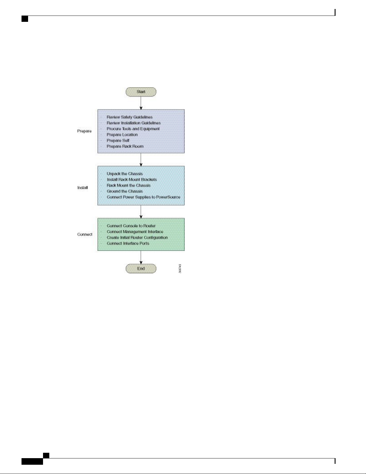
Review Installation Roadmap
The figure, Installation Workflow, lists the steps to install Cisco NCS 5500 Series fixed-port chassis and its
components and prepare the system for operation. Use this workflow as a reference to ensure that all components
CHAPTER 2
Hardware Installation Guide for Cisco NCS 5500 Series Fixed-Port Routers
3
Page 12
Review Safety Guidelines
are properly installed in the correct order. For information about a step, see the respective section of this
installation guide.
Figure 1: Installation Workflow
Prepare for Installation
Review Safety Guidelines
Before you perform any procedure in this document, review the safety guidelines in this section to avoid
injuring yourself or damaging the equipment. The following guidelines are for your safety and to protect
equipment. The guidelines do not include all hazards. Be alert.
Keep the work area clear, smoke and dust-free during and after installation. Do not allow dirt or debris
•
to enter into any laser-based components.
Do not wear loose clothing, jewelry, or other items that could get caught in the router or other associated
•
components.
Cisco equipment operates safely when used in accordance with its specifications and product-usage
•
instructions.
Be sure to power down a fixed configuration PDU or modular configuration power shelf before removing
•
it from the chassis.
Do not work alone if potentially hazardous conditions exist.
•
Hardware Installation Guide for Cisco NCS 5500 Series Fixed-Port Routers
4
Page 13

Prepare for Installation
Review Installation Guidelines
Take care when connecting units to the supply circuit so that wiring is not overloaded.
•
This equipment must be grounded. Never defeat the ground conductor or operate the equipment in the
•
absence of a suitably installed ground conductor. Contact the appropriate electrical inspection authority
or an electrician if you are uncertain that suitable grounding is available.
To prevent personal injury or damage to the chassis, never attempt to lift or tilt the chassis using the
•
handles on modules (such as power supplies, fans, or cards); these types of handles are not designed to
support the weight of the unit.
Hazardous voltage or energy is present on the backplane when the system is operating. Use caution
•
when servicing.
When installing or replacing the unit, the ground connection must always be made first and disconnected
•
last.
The rack stabilizing mechanism must be in place, or the rack must be bolted to the floor before you slide
•
the unit out for servicing. Failure to stabilize the rack can cause the rack to tip over.
Invisible laser radiation may be emitted from disconnected fibers or connectors. Do not stare into beams
•
or view directly with optical instruments.
Review Installation Guidelines
Before installing the chassis, verify that these guidelines are met:
Site is properly prepared so that there is sufficient room for installation and maintenance. For specifications
•
on the clearances required for chassis installation, see Clearance Requirements, on page 62.
Operating environment is within the ranges listed in Environmental and Physical Specifications, on
•
page 59
Chassis is mounted at the bottom of the rack if it is the only unit in the rack.
•
When mounting the chassis in a partially filled rack, load the rack from the bottom to the top with the
•
heaviest component at the bottom of the rack.
If the rack is provided with stabilizing devices, install the stabilizers before mounting or servicing the
•
chassis in the rack.
Airflow around the chassis and through the vents is unrestricted.
•
Cabling is away from sources of electrical noise, such as radios, power lines, and fluorescent lighting
•
fixtures. Make sure that the cabling is safely away from other devices that might damage the cables.
Procure Tools and Equipment
Obtain these necessary tools and equipment for installing the chassis:
Number 1 and number 2 Phillips screwdrivers with torque capability to rack-mount the chassis.
•
3/16-inch flat-blade screwdriver
•
Tape measure and level
•
Hardware Installation Guide for Cisco NCS 5500 Series Fixed-Port Routers
5
Page 14

Procure Tools and Equipment
•
•
•
•
•
•
•
•
•
•
Prepare for Installation
ESD wrist strap or other grounding device
Antistatic mat or antistatic foam
A Torx T15 screwdriver, or the Torx T15 key to install adapters.
Grounding cable (6 AWG recommended), sized according to local and national installation requirements;
the required length depends on the proximity of the switch to proper grounding facilities
Ground lug (1)
Crimping tool large enough to accommodate the girth of the lug
Wire-stripping tool
(ANSI) Pair of 19-inch mounting brackets
M4 screws to fix brackets (16)
M4 screws to fix ground lug (2)
Hardware Installation Guide for Cisco NCS 5500 Series Fixed-Port Routers
6
Page 15
Prepare for Installation
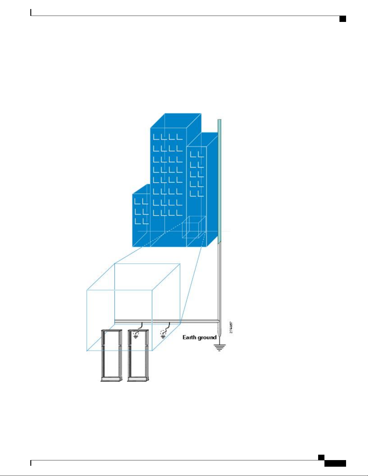
Prepare Your Location
This section illustrates how the building that houses the chassis must be properly grounded to the earth ground.
(See Prepare Your Location , on page 7 .)
Figure 2: Building with Rack Room Connected to Earth Ground
Prepare Your Location
Hardware Installation Guide for Cisco NCS 5500 Series Fixed-Port Routers
7
Page 16

Prepare Yourself
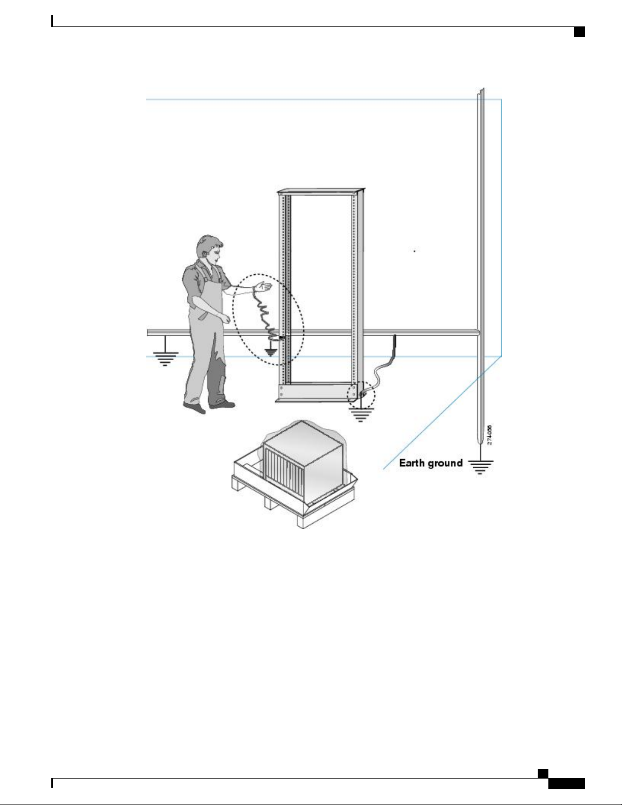
Prepare Yourself
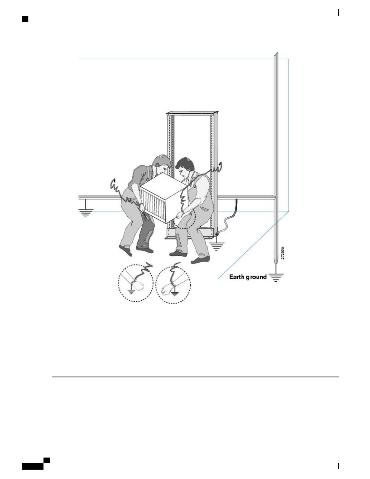
This section illustrates how to prepare yourself before removing the chassis from the sealed antistatic bag.
The figures show how to cuff the ESD strap around the wrist and the ground cord that connects the cuff to
the ground. ESD wrist straps are the primary means of controlling static charge on personnel.
Figure 3: Wearing the ESD Strap
Note: These images are for only representation purposes. The chassis' actual appearance and size may vary.
Prepare for Installation
Hardware Installation Guide for Cisco NCS 5500 Series Fixed-Port Routers
8
Page 17
Prepare for Installation
Prepare Yourself
Figure 4: Handling the Chassis
Hardware Installation Guide for Cisco NCS 5500 Series Fixed-Port Routers
9
Page 18
Prepare Rack for Chassis Installation
Prepare for Installation
Prepare Rack for Chassis Installation
Install the NCS 5500 Series chassis into a four-post 19-inch (48.3-cm) standard rack with standard horizontal
mounting rails. Before you move the chassis or mount the chassis into the rack, we recommend that you do
the following:
Step 1
Step 2
10
Place the rack where you plan to install the chassis. Ensure that the rack that the chassis is being installed is grounded
to earth ground as instructed in Prepare Your Location , on page 7.
Secure the rack to the floor.
To bolt the rack to the floor, a floor bolt kit (also called an anchor embedment kit) is required. For information on bolting
the rack to the floor, consult a company that specializes in floor mounting kits (such as Hilti; see Hilti.com for details).
Make sure that floor mounting bolts are accessible, especially if annual retorquing of bolts is required.
Hardware Installation Guide for Cisco NCS 5500 Series Fixed-Port Routers
Page 19

Prepare for Installation
Prepare Rack for Chassis Installation
Hardware Installation Guide for Cisco NCS 5500 Series Fixed-Port Routers
11
Page 20

Prepare Rack for Chassis Installation
Prepare for Installation
Hardware Installation Guide for Cisco NCS 5500 Series Fixed-Port Routers
12
Page 21
CHAPTER 3
Install the Chassis
Rack-Mount the Chassis on a 4-Post Rack, page 13
•
Rack-Mount the Chassis on a 2-Post Rack, page 22
•
Install the Air Filter, page 23
•
Ground the Chassis, page 25
•
Connect AC Power to the Chassis, page 28
•
Wiring a DC Power Connector, page 29
•
Connect DC Power to the Chassis, page 30
•
Rack-Mount the Chassis on a 4-Post Rack
Note
The Cisco NCS-55A1-24H, Cisco NCS 5501 and Cisco NCS 5501-SE can be installed in 4-post rack and
2-post rack.
This section describes how to use the rack-mount kit provided with the router to install the Cisco NCS
55A1-36H-S,Cisco NCS-55A1-24H, Cisco NCS 5501, Cisco NCS 5501-SE, Cisco NCS 5502, and Cisco
NCS 5502-SE routers into a cabinet or rack.
If the rack is on wheels, ensure that the brakes are engaged or that the rack is otherwise stabilized.Caution
The following table lists the items contained in the rack-mount kit provided routers.
Table 2: Cisco NCS-55A1-24H, Cisco NCS 5501 and Cisco NCS 5501-SE Router Rack-Mount Kit
Part DescriptionQuantity
Rack-mount brackets2
M4 x 6-mm Phillips flat-head screws12
Hardware Installation Guide for Cisco NCS 5500 Series Fixed-Port Routers
13
Page 22
Rack-Mount the Chassis on a 4-Post Rack
Table 3: Cisco NCS 55A1-36H-S Router Rack-Mount Kit
Install the Chassis
Part DescriptionQuantity
M5 x 12mm Phillips pan-head screws2
Rack-mount guides2
Rack-mount slider rails2
Grounding lug1
Part DescriptionQuantity
Rack-mount brackets2
M4 x 6-mm Phillips flat-head screws14
M4 x 6-mm Phillips pan-head screws2
Rack-mount guides2
Rack-mount slider rails2
Grounding cover plate1
Grounding lug1
Table 4: Cisco NCS 5502 and Cisco NCS 5502-SE Router Rack-Mount Kit
Part DescriptionQuantity
Rack-mount brackets2
M4 x 8-mm Phillips flat-head screws18
M4 x 8mm Phillips pan-head screws2
Rack-mount guides2
Rack-mount slider rails2
Grounding cover plate1
Grounding lug1
Hardware Installation Guide for Cisco NCS 5500 Series Fixed-Port Routers
14
Page 23

Install the Chassis
Rack-Mount the Chassis on a 4-Post Rack
Step 1
Install two rack-mount brackets to the router as follows:
a) Determine which end of the chassis is to be located in the cold aisle as follows:
If the router has port-side intake modules (fan modules with burgundy coloring), position the router so that the
•
ports are in the cold aisle.
If the router has port-side exhaust modules (fan modules with blue coloring), position the router so that the fan
•
and power supply modules are in the cold aisle.
b) Position a rack-mount bracket on the side of the chassis with its four holes aligned to four of the screw holes on the
side of the chassis, and then use four M4 flat-head screws to attach the bracket to the chassis.
Note
Note
Cisco NCS 55A1-36H-S, NCS 5502, NCS 5502 SE: Remove the grounding cover label and align the
grounding cover plate with the grounding holes in the chassis and attach the rack mount brackets.
You can align four of the holes in the rack-mount bracket to four of the screw holes on the front side of
chassis or four of the screw holes on the rear side of the chassis. The holes that you use depend on which
side your chassis need to be put in the cold aisle.
Hardware Installation Guide for Cisco NCS 5500 Series Fixed-Port Routers
15
Page 24
Rack-Mount the Chassis on a 4-Post Rack
Install the Chassis
Note
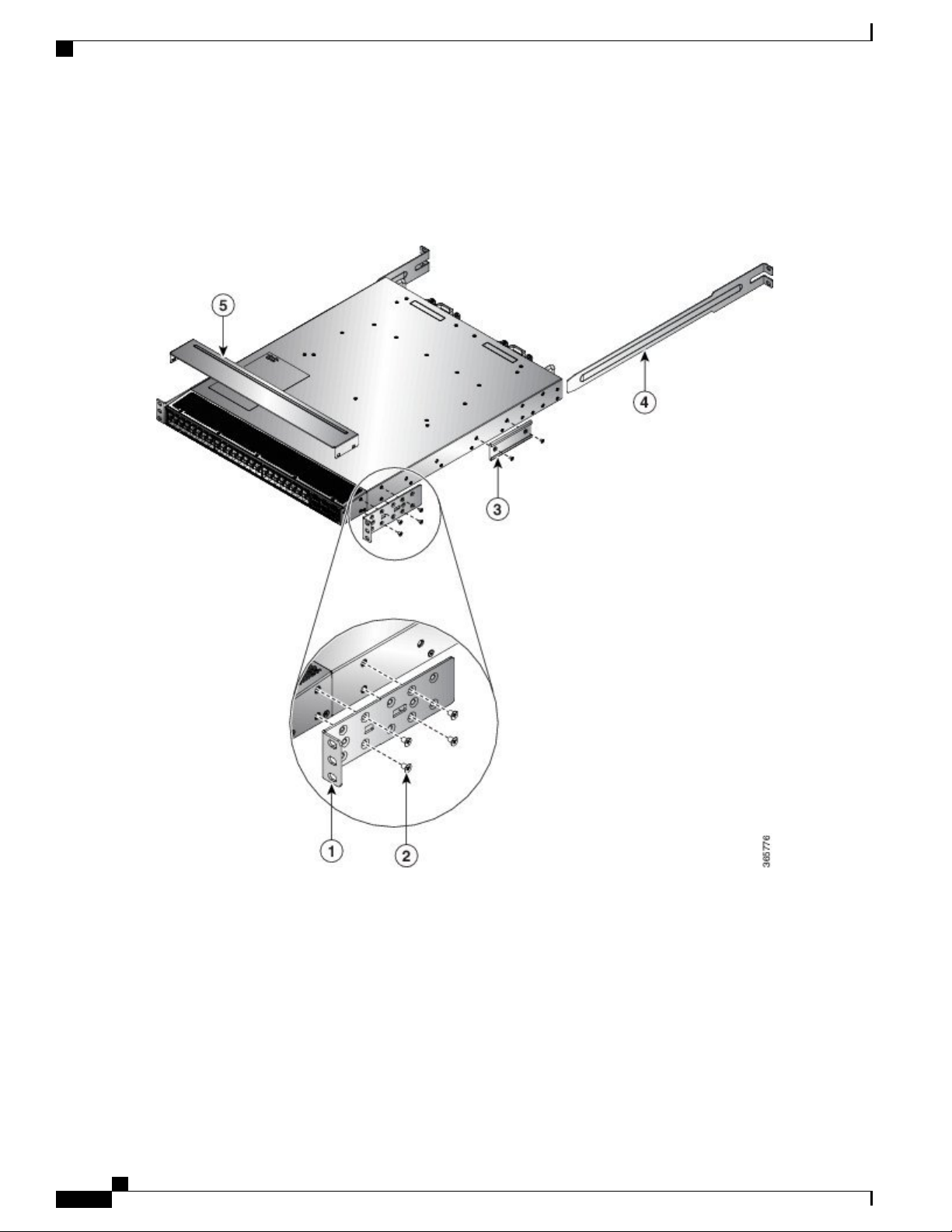
The following image shows the rack-mount brackets on the Cisco NCS 5501. The bracket installation is the
same for the Cisco NCS 5501-SE and Cisco NCS 55A1-24H.
Figure 5: Rack-mount brackets on the front side of Cisco NCS 5501
Figure 6: Rack-mount brackets on the rear side of Cisco NCS 5501
Hardware Installation Guide for Cisco NCS 5500 Series Fixed-Port Routers
16
Page 25

Install the Chassis
Rack-Mount the Chassis on a 4-Post Rack
Rack-mount slider rails4Rack-mount bracket1
Top plate5M4 x 6mm Phillips flat-head screws2
Rack-mount guides3
Hardware Installation Guide for Cisco NCS 5500 Series Fixed-Port Routers
17
Page 26

Rack-Mount the Chassis on a 4-Post Rack
Figure 7: Rack-Mount Brackets on the Front Side of Cisco NCS 55A1-36H-S
Install the Chassis
Hardware Installation Guide for Cisco NCS 5500 Series Fixed-Port Routers
18
Page 27

Install the Chassis
Figure 8: Rack-Mount Brackets on the Rear Side of Cisco NCS 55A1-36H-S
Rack-Mount the Chassis on a 4-Post Rack
M4 x 6mm Phillips flat-head screws5Grounding cover label1
Rack-mount guide6Grounding cover plate2
Rack-mount slider rails7Rack-mount brackets3
Top plate8M4 x 6mm Phillips flat-head screws4
Hardware Installation Guide for Cisco NCS 5500 Series Fixed-Port Routers
19
Page 28

Rack-Mount the Chassis on a 4-Post Rack
Figure 9: Rack-Mount Brackets on the Front Side of Cisco NCS 5502 and NCS 5502 SE
Install the Chassis
Figure 10: Rack-Mount Brackets on the Rear Side of Cisco NCS 5502 and NCS 5502 SE
Hardware Installation Guide for Cisco NCS 5500 Series Fixed-Port Routers
20
Page 29

Install the Chassis
Rack-Mount the Chassis on a 4-Post Rack
Step 2
Step 3
M4 x 8mm Phillips-Flat head screws5Grounding cover label1
Rack-mount guide6Grounding cover plate2
Rack-mount slider rails7Rack-mount brackets3
M4 x 8mm Phillips-Flat head screws4
c) Repeat Step 1b with the other rack-mount bracket on the other side of the router.
Cisco NCS-55A1-24H, Cisco NCS 55A1-36H-S, NCS 5501, NCS 5501-SE: If you are installing the router so that the
ports are in the cold aisle, install the top plate from the NEBS kit by pressing the ends of the plate on to the rack-mount
brackets. The plate is required for NEBS compliance.
Install the two rack-mount guides on the chassis as follows:
a) Position a rack-mount guides on the side of the chassis with its two holes aligned to the two screw holes on the side
of the chassis, and then use two M4 screws to attach the guides to the chassis.
Hardware Installation Guide for Cisco NCS 5500 Series Fixed-Port Routers
21
Page 30

Rack-Mount the Chassis on a 2-Post Rack
b) Repeat with the other rack-mount guides on the other side of the router.
Install the Chassis
Step 4
Install the slider rails to the rack as follows:
a) Position the slider rails at the desired levels on the back side of the rack and use two 12-24 screws or two 10-32
screws, depending on the rack thread type, to attach the rails to the rack.
Note
For racks with square holes, you might need to position a 12-24 cage nut behind each mounting hole in a
slider rail before using a 12-24 screw.
b) Repeat with the other slider rail on the other side of the rack.
c) Use a tape measure and level to verify that the rails are at the same height and horizontal.
Step 5
Insert the router into the rack and attach it as follows:
a) Holding the router with both hands, position the back of the router between the front posts of the rack.
b) Align the two rack-mount guides on either side of the router with the slider rails installed in the rack. Slide the
rack-mount guides onto the slider rails, and then gently slide the router all the way into the rack.
Note
If the router does not slide easily, try realigning the rack-mount guides on the slider
rails.
c) Holding the chassis level, insert two screws (12-24 or 10-32, depending on the rack type) through the holes in each
of the rack-mount brackets and into the cage nuts or threaded holes in the rack-mounting rail.
d) Tighten the 10-32 screws to 20 in-lb (2.26 N.m) or tighten the 12-24 screws to 30 in-lb (3.39 N.m).
Rack-Mount the Chassis on a 2-Post Rack
Step 1
Note
The Cisco NCS-55A1-24H, Cisco NCS 5501 and Cisco NCS 5501-SE can be installed in 4-post rack and
2-post rack.
This section describes how to use the rack-mount kit provided with the router to install the Cisco
NCS-55A1-24H, Cisco NCS 5501 and Cisco NCS 5501-SE router into a cabinet or 2-post rack.
If the rack is on wheels, ensure that the brakes are engaged or that the rack is otherwise stabilized.Caution
The following table lists the items contained in the rack-mount kit provided with the routers.
Table 5: Cisco NCS-55A1-24H, Cisco NCS 5501 and Cisco NCS 5501-SE Router Rack-Mount Kit
Install two rack-mount brackets to the router as follows:
Part DescriptionQuantity
Rack-mount brackets2
M4 x 0.7 x 6-mm Phillips flat-head screws8
Hardware Installation Guide for Cisco NCS 5500 Series Fixed-Port Routers
22
Page 31

Install the Chassis
a) Determine which end of the chassis is to be located in the cold aisle as follows:
b) With the bracket ears facing toward the center of the chassis, position a front rack-mount bracket on the side of the
chassis so that the four holes are aligned to four of the screw holes on the side of the chassis.
c) Use four M4 screws to attach the bracket to the chassis
d) Repeat Steps 1b and 1c with the other rack-mount bracket on the other side of the router.
Note
Figure 11: Rack-mount brackets on Cisco NCS 5501
Install the Air Filter
If the router has port-side intake modules (fan modules with burgundy coloring), position the router so that its
•
ports will be in the cold aisle.
If the router has port-side exhaust modules (fan modules with blue coloring), position the router so that its fan
•
and power supply modules will be in the cold aisle.
The following image shows the rack-mount brackets on the Cisco NCS 5501. The bracket installation is the
same for the Cisco NCS 5501-SE and Cisco NCS 55A1-24H.
Step 2
Install the router onto the 2-post rack as follows:
a) With two people, lift the router into position between the two rack posts.
b) Move the router until the rack-mount brackets come in contact with two rack posts.
c) Hold the chassis level while the second person inserts two screws (12-24 or 10-32, depending on the rack type) in
each of the two rack-mount brackets (using a total of four screws) and into the cage nuts or threaded holes in the
vertical rack-mounting rails.
d) Tighten the 10-32 screws to 20 in-lb (2.26 N.m) or tighten the 12-24 screws to 30 in-lb (3.39 N.m).
Install the Air Filter
Air filters are available for Cisco NCS-5502-SE and NCS-5502. The air filters are for one time use only.Note
Hardware Installation Guide for Cisco NCS 5500 Series Fixed-Port Routers
23
Page 32

Install the Air Filter
Install the Chassis
Step 1
Note
In general, we recommend that you inspect the air filter every three months and replace, if necessary,
every 6 months.
If air filters need replacement, follow this procedure.
Install the air filter on the port side inlet as follows:
a) Using two hands to support the air filer, orient it so that the ridge on the front of the air filter faces outward from the
front of the chassis and the wire-grid backing support is facing up.
Figure 12: Port side Inlet Air Filter
Step 2
24
b) Slide the air filter into the air filter slot until it is seated fully within the slot.
c) Hold the filter cover plate in place and tighten the middle panel to the top and bottom panels with six thumb screws.
And, tighten the top and bottom panels separately to the faceplate using four screws.
Install the air filter to the port side exhaust as follows:
Hardware Installation Guide for Cisco NCS 5500 Series Fixed-Port Routers
Page 33

Install the Chassis
a) Install the two standoffs to the chassis.
Figure 13: Port Side Exhaust Air Filter
Ground the Chassis
b) Install the air filter to the chassis using two thumb screws.
c) Install the side filter to the chassis using a thumb screw and a captive screw.
Ground the Chassis
Warning
Warning
Warning
Statement 1024
This equipment must be grounded. Never defeat the ground conductor or operate the equipment in the
absence of a suitably installed ground conductor. Contact the appropriate electrical inspection authority
or an electrician if you are uncertain that suitable grounding is available.
Statement 1046
When installing or replacing the unit, the ground connection must always be made first and disconnected
last.
Statement 1025
Use copper conductors only.
Hardware Installation Guide for Cisco NCS 5500 Series Fixed-Port Routers
25
Page 34

Ground the Chassis
Install the Chassis
Step 1
Step 2
Caution
Grounding the chassis is required, even if the rack is already grounded. A grounding pad with two threaded
holes is provided on the chassis for attaching either a grounding lug or grounding cover plate. The ground
lug must be NRTL-listed. In addition, a copper conductor (wires) must be used and the copper conductor
must comply with NEC code for ampacity.
Caution
When terminating the frame ground, do not use soldering lug connectors, screwless (push-in) connectors,
quick connect connectors, or other friction-fit connectors.
Verify that the office ground cable is connected to the top of the rack and the office ground, according to local site
practice.
Attach the ground cable:
Cisco NCS-55A1-24H, Cisco NCS 5501, Cisco NCS 5501-SE: Attach one end of the shelf ground cable (#6 AWG
•
cable) to the ground point on the rear of the chassis using the specified dual-hole lug connector.
Figure 14: Cisco NCS-55A1-24H, Cisco NCS 5501, Cisco NCS 5501-SE Ground Lug
M5 x 12mm pan-head screws2Grounding lug1
Hardware Installation Guide for Cisco NCS 5500 Series Fixed-Port Routers
26
Page 35

Install the Chassis
Ground the Chassis
Cisco NCS 55A1-36H-S, NCS 5502 and NCS 5502-SE: Attach one end of the shelf ground cable (#6 AWG cable)
•
to the grounding cover plate using the specified dual-hole lug connector.
Figure 15: NCS 55A1-36H-S Ground Lug
Figure 16: NCS 5502 Ground Lug
M4 x 6mm pan-head screws2Grounding lug1
M4 x 8mm pan-head screws2Grounding lug1
Hardware Installation Guide for Cisco NCS 5500 Series Fixed-Port Routers
27
Page 36

Connect AC Power to the Chassis
Install the Chassis
Step 3
Step 4
Tighten the M4 pan-head screws to torque value of 11.5 in-lbs (1.3 N-m).
Attach the other end of the shelf ground cable to the bay frame using a dual-hole lug connector according to the equipment
rack frame specifications.
Connect AC Power to the Chassis
Caution
Note
The chassis relies on the protective devices in the building installation to protect against short circuit,
overcurrent, and ground faults. Ensure that the protective devices comply with local and national electrical
codes.
Cisco NCS-55A1-24H, Cisco NCS 5501, Cisco NCS 5501-SE—To provide full output power of 1100
W, the nominal voltage rating value ranges between 100 V to 240 V, depending on the standards in various
countries.
Cisco NCS 55A1-36H-S, Cisco NCS 5502, Cisco NCS 5502-SE—To provide full output power of 2000
W, the nominal voltage rating value ranges between 200V to 240V, depending on the standards in various
countries.
Hardware Installation Guide for Cisco NCS 5500 Series Fixed-Port Routers
28
Page 37

Install the Chassis
Wiring a DC Power Connector
Step 1
Step 2
Note
Verify that the AC cable is installed in the correct AC source panel.
Attach the AC power cable to the cable connector in the AC power module.
Figure 17: Connecting AC Power
A dual pole breaker is needed for the installation. The rating of the dual pole breaker for 110 V is 20 A
and for 220 V is 16 A. The minimum cable size is 14 AWG for 110 V and 16 AWG for 220 V.
Step 3
Step 4
Step 5
Place the cable through the opening in the cable clamp.
Slide the cable clamp toward the plug.
Close the cable clamp on the shoulder of the power cable to secure the power cable.
Wiring a DC Power Connector
Warning
Statement 1022
A readily accessible two-poled disconnect device must be incorporated in the fixed wiring.
Hardware Installation Guide for Cisco NCS 5500 Series Fixed-Port Routers
29
Page 38

Connect DC Power to the Chassis
Install the Chassis
Step 1
Warning
Statement 1045
This product requires short-circuit (overcurrent) protection, to be provided as part of the building installation.
Install only in accordance with national and local wiring regulations.
Warning
Statement 1046
When installing or replacing the unit, the ground connection must always be made first and disconnected
last.
Warning
Statement 1074
Installation of the equipment must comply with local and national electrical codes.
Before installing a DC power supply to the switch, you will need to attach DC connection wires that you
provide to the DC power connector included in the DC power supply's accessory kit. For 240-380 VDC power
supply, the duel-pole breaker or fuse rating is 20 A. For 40-72 VDC power supply, the single breaker or fuse
is 40 A. To wire the connector:
Use a 1/8" flat head screwdriver or No. 1 Phillips head screwdriver to loosen the set screws on the connector to freely
accept the power wires.
The connector will accept 8-24 AWG wires, 10 GA wires and wire temperature ratings of 90 ºC, use what your local
electrical code calls for.
Step 2
Step 3
Strip 1/2" of insulation off the DC wires you will use.
Insert the black (DC negative) wire into the right aperture on the connector and tighten down the connection set screw.
Finger tight or about 3 ft./lbs should be sufficient.
Step 4
Insert the red (DC positive) wire into the left aperture on the connector and tighten down the connection set screw.
Do not tighten over 0.7 Nm.
Connect DC Power to the Chassis
Caution
The chassis relies on the protective devices in the building installation to protect against short circuit,
overcurrent, and ground faults. Ensure that the protective devices comply with local and national electrical
codes.
Hardware Installation Guide for Cisco NCS 5500 Series Fixed-Port Routers
30
Page 39

Install the Chassis
Connect DC Power to the Chassis
Step 1
Step 2
Step 3
Step 4
Step 5
Note
A dual pole breaker is needed for the installation. For NCS 5501 and 5501-SE, the rating of the dual pole
breaker is 40A with wire size of 10 AWG. For Cisco NCS 55A1-36H-S, NCS 5502 and 5502-SE, the
rating of the dual pole breaker is 80A with wire size of 6 AWG.
Verify that the correct fuse panel is installed in the top mounting space.
For a 40-72 VDC power supply for maximum 1100 W power, the fuse rating must be 80 A. There is an option for 240-380
VDC power supply for maximum 1100 W power, the fuse rating must not exceed 40 A.
Measure and cut the cables as needed to reach the chassis from the fuse panel.
Dress the power according to local practice.
Connect the office battery and return cables according to the fuse panel engineering specifications.
Insert the DC connector into the DC receptacle on the power supply.
Figure 18: Connecting DC Power
Step 6
Ensure that the locking mechanism has engaged.
Hardware Installation Guide for Cisco NCS 5500 Series Fixed-Port Routers
31
Page 40

Connect DC Power to the Chassis
Install the Chassis
Hardware Installation Guide for Cisco NCS 5500 Series Fixed-Port Routers
32
Page 41

Connect Router to the Network
Guidelines for Connecting Ports, page 33
•
Connect to the Console Port, page 34
•
Connect to the Management Ethernet Port, page 36
•
Creating the Initial Router Configuration, page 37
•
Installing and Removing Transceiver Modules, page 39
•
Connecting Interface Ports, page 48
•
Maintaining Transceivers and Optical Cables, page 49
•
Guidelines for Connecting Ports
Depending on the chassis and installed line cards, you can use Quad Small Form-Factor Pluggable Plus
(QSFP+), QSFP28, SFP, SFP+, and RJ-45 connectors to connect the ports on the line cards to other network
devices.
To prevent damage to the fiber-optic cables that can separate from their cables, Cisco recommends that you
keep the transceivers disconnected from their fiber-optic cables when installing the transceiver in the line
card. Before removing such a transceiver from the router, remove the cable from the transceiver.
To maximize the effectiveness and life of your transceivers and optical cables, do the following:
CHAPTER 4
Wear an ESD-preventative wrist strap that is connected to an earth ground whenever handling transceivers.
•
The router is typically grounded during installation and provides an ESD port to which you can connect
your wrist strap.
Do not remove and insert a transceiver more often than is necessary. Repeated removals and insertions
•
can shorten its useful life.
Keep the transceivers and fiber-optic cables clean and dust free to maintain high signal accuracy and to
•
prevent damage to the connectors. Attenuation (loss of light) is increased by contamination and should
be kept below 0.35 dB.
Clean these parts before installation to prevent dust from scratching the fiber-optic cable ends.
◦
Hardware Installation Guide for Cisco NCS 5500 Series Fixed-Port Routers
33
Page 42

Connect to the Console Port
•
Connect Router to the Network
Clean the connectors regularly; the required frequency of cleaning depends upon the environment.
◦
In addition, clean connectors if they are exposed to dust or accidentally touched. Both wet and dry
cleaning techniques can be effective; refer to your site's fiber-optic connection cleaning procedures.
Do not touch the ends of connectors. Touching the ends can leave fingerprints and cause other
◦
contamination.
Inspect routinely for dust and damage. If you suspect damage, clean and then inspect fiber ends under
a microscope to determine if damage has occurred.
Warning
Statement 1051—Laser Radiation
Invisible laser radiation may be emitted from disconnected fibers or connectors. Do not stare into beams
or view directly with optical instruments.
Connect to the Console Port
Before you create a network management connection for the router or connect the router to the network, you
must create a local management connection through a console terminal and configure an IP address for the
router. You also can use the console to perform the following functions (each of which can be performed
through the management interface after you make that connection):
Configure the router using the command-line interface (CLI).
•
Monitor network statistics and errors.
•
Configure Simple Network Management Protocol (SNMP) agent parameters.
•
Download software updates.
•
The system console port is an RJ-45 receptacle for connecting a data terminal to perform the initial configuration
of NCS 5500 fixed-port chassis. The console cable is shipped with the hardware.
Hardware Installation Guide for Cisco NCS 5500 Series Fixed-Port Routers
34
Page 43

Connect Router to the Network
Connect to the Console Port
Step 1
Step 2
Step 3
Console port2Management Ethernet port1
Follow this procedure to connect a data terminal to the console port.
Before You Begin
The router must be fully installed in its rack, connected to a power source, and grounded.
•
The necessary cabling for the console, management, and network connections must be available.
•
An RJ-45 rollover cable and DB9F/RJ-45 adapter are provided in the router accessory kit.
◦
Network cabling should already be routed to the location of the installed router.
◦
Set your terminal to these operational values: 115200 bps, 8 data bits, no parity, 2 stop bits (115200 8N1).
Attach the terminal end of the cable to the interface port on the data terminal.
Attach the other end of the cable to the console port.
Table 6: RJ-45 Straight-through Cable Pin-outs
SignalRJ-45 Pin
1
2
—
—
Tx3
Hardware Installation Guide for Cisco NCS 5500 Series Fixed-Port Routers
35
Page 44

Connect to the Management Ethernet Port
Connect Router to the Network
SignalRJ-45 Pin
Ground (GND)4
GND5
Rx6
7
8
—
—
Connect to the Management Ethernet Port
The management Ethernet port provides out-of-band management, which enables you to use the command-line
interface (CLI) to manage the router by its IP address. This port uses a 10/100/1000 Ethernet connection with
an RJ-45 interface.
Note
To prevent an IP address conflict, do not connect the management Ethernet port until the initial configuration
is complete.
To connect cables to the system management port, attach Category 5 cables directly to the RJ-45 receptacle
on the management Ethernet port.
Console port2Management Ethernet port1
Hardware Installation Guide for Cisco NCS 5500 Series Fixed-Port Routers
36
Page 45

Connect Router to the Network
Creating the Initial Router Configuration
Note
To comply with GR-1089-CORE, the intra-building port(s) of the equipment must use shielded
intra-building cabling/wiring that is grounded at both ends.
Before You Begin
You must have completed the initial router configuration.
Step 1
Step 2
Plug the cable directly into the RJ-45 receptacle.
Connect the network end of your RJ-45 cable to a switch, hub, repeater, or other external equipment.
Creating the Initial Router Configuration
You must assign an IP address to the router management interface so that you can then connect the router to
the network.
When you initially power up the router, it boots up and asks you a series of questions to configure the router.
To enable you to connect the router to the network, you can use the default choices for each configuration
except the IP address, which you must provide. .
Step 1
Step 2
You should also know the unique name needed to identify the router among the devices in the network.Note
Before You Begin
A console device must be connected with the router.
•
The router must be connected to a power source.
•
Determine the IP address and netmask needed for the following interfaces:
•
Management interface: MgmtEth0/RP0/CPU0/0 and MgmtEth0/RP1/CPU0/0.
◦
Power up the router by connecting each installed power supply to an AC circuit.
If you are using the combined or power-supply (n+1) power mode, connect all of the power supplies to the same AC
circuit. If you are using the input-source (n+n) power mode, connect half of the power supplies to one AC circuit and
the other half to another AC circuit.
The Input and Output LEDs on each power supply light up (green) when the power supply units are sending power to
the router, and the software asks you to specify a password to use with the router.
When the system is booted up for the first time, a new username and a password is to be created. The following prompt
appears:
Hardware Installation Guide for Cisco NCS 5500 Series Fixed-Port Routers
37
Page 46

Connect Router to the Network
Creating the Initial Router Configuration
!!!!!!!!!!!!!!!!!!!! NO root-system username is configured. Need to configure root-system username.
!!!!!!!!!!!!!!!!!!!!
--- Administrative User Dialog ---
Enter root-system username:
% Entry must not be null.
Enter root-system username: root
Enter secret:
Use the 'configure' command to modify this configuration.
User Access Verification
Username: root
Password:
RP/0/RP0/CPU0:ios#
Step 3
Enter a new password to use for this router.
The software checks the security strength of your password and rejects your password if it is not considered to be a strong
password. To increase the security strength of your password, make sure that it adheres to the following guidelines:
At least eight characters
•
Minimizes or avoids the use of consecutive characters (such as "abcd")
•
Minimizes or avoids repeating characters (such as "aaabbb")
•
Does not contain recognizable words from the dictionary
•
Does not contain proper names
•
Contains both uppercase and lowercase characters
•
Contains numbers as well as letters
•
Examples of strong passwords include the following:
If2CoM18
•
2004AsdfLkj30
•
Cb1955S21
•
Clear text passwords cannot include the dollar sign ($) special character.Note
If a password is trivial (such as a short, easy-to-decipher password), the software will reject your password
Tip
configuration. Be sure to configure a strong password as explained in this step. Passwords are case sensitive.
If you enter a strong password, the software asks you to confirm the password.
Step 4
38
Enter the same password again.
If you enter the same password, the software accepts the password .
Hardware Installation Guide for Cisco NCS 5500 Series Fixed-Port Routers
Page 47

Connect Router to the Network
Installing and Removing Transceiver Modules
What to Do Next
1
Enter the IP address for the management interface.
The software asks for the Mgmt0 IPv4 netmask.
2
Enter a network mask for the management interface.
The software asks if you need to edit the configuration.
3
Enter no to not edit the configuration.
The software asks if you need to save the configuration.
4
Enter yes to save the configuration.
Installing and Removing Transceiver Modules
Installing and Removing SFP Modules
Before you remove or install an SFP or SFP+ module, read the installation information in this section.
Warning
Caution
Invisible laser radiation may be emitted from disconnected fibers or connectors. Do not stare into beams
or view directly with optical instruments. Statement 1051
Protect the line card by inserting a clean SFP/SFP+ module cage cover, shown in the figure below, into
the optical module cage when there is no SFP or SFP+ module installed.
Figure 19: SFP/SFP+ Module Cage Cover
Hardware Installation Guide for Cisco NCS 5500 Series Fixed-Port Routers
39
Page 48

Installing and Removing SFP Modules
Connect Router to the Network
Caution
Protect the SFP or SFP+ modules by inserting clean dust covers into them after the cables are removed.
Be sure to clean the optic surfaces of the fiber cables before you plug them back into the optical ports of
another module. Avoid getting dust and other contaminants into the optical ports of your SFP or SFP+
modules, because the optics do not work correctly when obstructed with dust.
Caution
We strongly recommended that you do not install or remove the SFP or SFP+ module with fiber-optic
cables attached to it because of the potential to damage the cable, the cable connector, or the optical
interfaces in the module. Disconnect all cables before removing or installing an SFP or SFP+ module.
Removing and inserting an module can shorten its useful life, so you should not remove and insert modules
any more often than is absolutely necessary.
Note
When installing an SFP or SFP+ module, you should hear a click as the triangular pin on the bottom of
the module snaps into the hole in the receptacle, indicating that the module is correctly seated and secured
in the receptacle. Verify that the modules are completely seated and secured in their assigned receptacles
on the line card by firmly pushing on each SFP or SFP+ module.
Bale Clasp SFP or SFP+ Module
The bale clasp SFP or SFP+ module has a clasp that you use to remove or install the module (see the figure
below).
Figure 20: Bale Clasp SFP or SFP+ Module
Hardware Installation Guide for Cisco NCS 5500 Series Fixed-Port Routers
40
Page 49

Connect Router to the Network
Installing a Bale Clasp SFP or SFP+ Module
To install this type of SFP or SFP+ module, follow these steps:
Installing and Removing SFP Modules
Step 1
Step 2
Step 3
Attach an ESD-preventive wrist or ankle strap and follow its instructions for use.
Close the bale clasp before inserting the SFP module.
Line up the SFP module with the port and slide it into the port (see the figure below).
Figure 21: Installing a Bale Clasp SFP Module into a Port
Note
When installing an SFP or SFP+ module, you should hear a click as the triangular pin on the bottom of the SFP
module snaps into the hole in the receptacle, indicating that the module is correctly seated and secured in the
receptacle. Verify that the SFP modules are completely seated and secured in their assigned receptacles on the
line card by firmly pushing on each SFP module.
Hardware Installation Guide for Cisco NCS 5500 Series Fixed-Port Routers
41
Page 50

Installing and Removing SFP Modules
Removing a Bale Clasp SFP or SFP+ Module
To remove this type of SFP or SFP+ module, follow these steps:
Connect Router to the Network
Step 1
Step 2
Step 3
Step 4
Attach an ESD-preventive wrist or ankle strap and follow its instructions for use.
Disconnect and remove all interface cables from the ports; note the current connections of the cables to the ports on the
line card.
Open the bale clasp on the SFP module with your index finger, as shown in the figure below. If the bale clasp is obstructed
and you cannot use your index finger to open it, use a small flat-blade screwdriver or other long, narrow instrument to
open the bale clasp.
Grasp the SFP module between your thumb and index finger and carefully remove it from the port, as shown in the figure
below.
Figure 22: Removing a Bale Clasp SFP or SFP+ Module
Hardware Installation Guide for Cisco NCS 5500 Series Fixed-Port Routers
42
Page 51

Connect Router to the Network
Installing and Removing SFP Modules
Step 5
Step 6
Place the removed SFP module on an antistatic mat, or immediately place it in a static shielding bag if you plan to return
it to the factory.
Protect your line card by inserting clean SFP module cage covers into the optical module cage when there is no SFP
module installed.
Hardware Installation Guide for Cisco NCS 5500 Series Fixed-Port Routers
43
Page 52

Connect Router to the Network
Installing and Removing QSFP+/QSFP28 Transceiver Modules
Installing and Removing QSFP+/QSFP28 Transceiver Modules
This section provides the installation, cabling, and removal instructions for the 40-Gigabit Quad Small
Form-Factor Pluggable Plus (QSFP+) and 100 Gigabit (QSFP28) transceiver modules. The modules are
hot-swappable input/output (I/O) devices that connect the system’s module port electrical circuitry with either
a copper or a fiber-optic network.
Overview
The 40-Gigabit (GE) QSFP+ and 100 Gigabit (QSFP28) transceiver module is a hot-swappable, parallel
fiber-optical module with four independent optical transmit and receive channels. These channels can terminate
in another 40-Gigabit QSFP+ transceiver, or the channels can be broken out to four separate 10-Gigabit SFP+
transceivers. The QSFP+ transceiver module connects the electrical circuitry of the system with an optical
external network.
The following figure shows the 40-Gigabit optical QSFP+ transceiver. The transceiver is used primarily in
short reach applications in switches, routers, and data center equipment where it provides higher density than
SFP+ modules. The 100-Gigabit optical QSFP28 transceiver is similar to the 40-Gigabit optical QSFP
transceiver
Figure 23: 40-Gigabit QSFP+ Transceiver Module (Optical)
Bail-clasp latch2
Required Tools and Equipment
You need these tools to install the 40-Gigabit QSFP+ / 100-Gigabit QSFP28 transceiver modules:
Wrist strap or other personal grounding device to prevent ESD occurrences.
•
Antistatic mat or antistatic foam to set the transceiver on.
•
Electrical connection to the module circuitry340GBASE QSFP+ transceiver body1
Fiber-optic end-face cleaning tools and inspection equipment.
•
For information on inspecting and cleaning fiber-optic connections, see Maintaining Transceivers and Optical
Cables.
Hardware Installation Guide for Cisco NCS 5500 Series Fixed-Port Routers
44
Page 53

Connect Router to the Network
Installing and Removing QSFP+/QSFP28 Transceiver Modules
Installing the 40-Gigabit QSFP+ or 100-Gigabit Transceiver Module
The QSFP+ or QSFP28 transceiver module can have either a bail-clasp latch or a pull-tab latch. Installation
procedures for both types of latches are provided.
Step 1
Step 2
Step 3
Step 4
Step 5
Step 6
Step 7
Caution
The QSFP+ or QSFP28 transceiver module is a static-sensitive device. Always use an ESD wrist strap or
similar individual grounding device when handling QSFP+ or QSFP28 transceiver modules or coming
into contact with system modules.
To install an QSFP+ or QSFP28 transceiver module, follow these steps:
Attach an ESD wrist strap to yourself and a properly grounded point on the chassis or the rack.
Remove the QSFP+ or QSFP28 transceiver module from its protective packaging.
Check the label on the QSFP+ or QSFP28 transceiver module body to verify that you have the correct model for your
network.
For optical QSFP+ or QSFP28 transceiver modules, remove the optical bore dust plug and set it aside.
For QSFP+ or QSFP28 transceiver modules equipped with a pull-tab, hold the transceiver so that the identifier label is
on the top.
For QSFP+ or QSFP28 transceiver modules equipped with a bail-clasp latch, keep the bail-clasp aligned in a vertical
position.
Align the QSFP+ or QSFP28 transceiver module in front of the module’s transceiver socket opening and carefully slide
the QSFP+ or QSFP28 transceiver into the socket until the transceiver makes contact with the socket electrical connector
(see the figure below).
Figure 24: Installing the 40-Gigabit QSFP+ or 100-Gigabit QSFP28 Transceiver Module (Optical Transceiver Equipped with a Bail-Clasp
Latch Shown)
Hardware Installation Guide for Cisco NCS 5500 Series Fixed-Port Routers
45
Page 54

Installing and Removing QSFP+/QSFP28 Transceiver Modules
Connect Router to the Network
Step 8
Press firmly on the front of the QSFP+ or QSFP28 transceiver module with your thumb to fully seat the transceiver in
the module’s transceiver socket (see the below figure).
If the latch is not fully engaged, you might accidentally disconnect the QSFP+ or QSFP28 transceiver module.Caution
Figure 25: Seating the 40-Gigabit QSFP+ or 100-Gigabit QSFP28 Transceiver Module (Optical Transceiver Equipped with a Bail-Clasp
Latch Shown)
Step 9
For optical QSFP+ or QSFP28 transceiver modules, reinstall the dust plug into the QSFP+ or QSFP28 transceivers optical
bore until you are ready to attach the network interface cable. Do not remove the dust plug until you are ready to attach
the network interface cable.
Attaching the Optical Network Cable
Before You Begin
Before removing the dust plugs and making any optical connections, follow these guidelines:
Keep the protective dust plugs installed in the unplugged fiber-optic cable connectors and in the transceiver
•
optical bores until you are ready to make a connection.
Inspect and clean the MPO connector end faces just before you make any connections.
•
Hardware Installation Guide for Cisco NCS 5500 Series Fixed-Port Routers
46
Page 55

Connect Router to the Network
40-Gigabit QSFP+ or QSFP28 transceiver modules are keyed to prevent incorrect insertion.Note
Installing and Removing QSFP+/QSFP28 Transceiver Modules
Grasp the MPO connector only by the housing to plug or unplug a fiber-optic cable.
•
Step 1
Step 2
Step 3
Step 4
Note
The multiple-fiber push-on (MPO) connectors on the optical QSFP+ or QSFP28 transceivers support
network interface cables with either physical contact (PC) or ultra-physical contact (UPC) flat polished
face types. The MPO connectors on the optical QSFP+ or QSFP28 transceivers do not support network
interface cables with an angle-polished contact (APC) face type.
Remove the dust plugs from the optical network interface cable MPO connectors. Save the dust plugs for future use.
Inspect and clean the MPO connector’s fiber-optic end faces.
Remove the dust plugs from the QSFP+ or QSFP28 transceiver module optical bores.
Immediately attach the network interface cable MPO connectors to the QSFP+ or QSFP28 transceiver module (see the
figure below).
Figure 26: Cabling a 40-Gigabit QSFP+ or QSFP28 Transceiver Module
Removing the 40-Gigabit QSFP+ or 100-Gigabit QSFP28 Transceiver Module
Caution
The QSFP+ or QSFP28 transceiver module is a static-sensitive device. Always use an ESD wrist strap or
similar individual grounding device when handling QSFP+ or QSFP28 transceiver modules or coming
into contact with modules.
Hardware Installation Guide for Cisco NCS 5500 Series Fixed-Port Routers
47
Page 56

Connecting Interface Ports
To remove a QSFP+ or QSFP28 transceiver module, follow these steps:
Connect Router to the Network
Step 1
Step 2
Step 3
For optical QSFP+ or QSFP28 transceiver modules, disconnect the network interface cable from the QSFP+ or QSFP28
transceiver connector.
For QSFP+ or QSFP28 transceiver modules equipped with a bail-clasp latch (see the below figure, top view):
a) Pivot the bail-clasp down to the horizontal position.
b) Immediately install the dust plug into the transceivers optical bore.
c) Grasp the sides of the QSFP+ or QSFP28 transceiver and slide it out of the module socket.
For QSFP+ or QSFP28 transceivers equipped with a pull tab latch (see the below figure, bottom view):
a)
Immediately install the dust plug into the transceiver’s optical bore.
b) Grasp the tab and gently pull to release the transceiver from the socket.
c) Slide the transceiver out of the socket.
Figure 27: Removing the 40-Gigabit QSFP+ or 100-Gigabit QSFP28 Transceiver Module
Step 4
Place the QSFP+ or QSFP28 transceiver module into an antistatic bag.
Connecting Interface Ports
You can connect optical interface ports on line cards with other devices for network connectivity.
Hardware Installation Guide for Cisco NCS 5500 Series Fixed-Port Routers
48
Page 57

Connect Router to the Network
Connecting a Fiber-Optic Port to the Network
Depending on the line card model that you are using, you can use either QSFP+ or QSFP28 transceivers.
Some of these transceivers work with fiber-optic cables that you attach to the transceivers and other transceivers
work with pre-attached copper cables. When installing fiber-optic cables for a port, you must install SFP
transceivers for 1-Gigabit optical ports or install SFP+ transceivers for 10-Gigabit optical ports or QSFP+
transceivers for 100-Gigabit ports before installing the fiber-optic cable in the transceivers.
Connecting a Fiber-Optic Port to the Network
Caution
Removing and installing a transceiver can shorten its useful life. Do not remove and insert transceivers
more often than is absolutely necessary. It is recommended that you disconnect cables before installing
or removing transceivers to prevent damage to the cable or transceiver.
Disconnecting Optical Ports from the Network
When removing fiber-optic transceivers, you must remove the fiber-optic cables from a transceiver before
removing the transceiver from the port.
Maintaining Transceivers and Optical Cables
Transceivers and fiber-optic cables must be kept clean and dust free to maintain high signal accuracy and
prevent damage to the connectors. Attenuation (loss of light) is increased by contamination and should be
below 0.35 dB.
Consider the following maintenance guidelines:
Transceivers are static sensitive. To prevent ESD damage, wear an ESD-preventative wrist strap that is
•
connected to the grounded chassis.
Do not remove and insert a transceiver more often than is necessary. Repeated removals and insertions
•
can shorten its useful life.
Keep all optical connections covered when not in use. Clean them before using to prevent dust from
•
scratching the fiber-optic cable ends.
Do not touch the ends of connectors. Touching the ends can leave fingerprints and cause other
•
contamination.
Clean the connectors regularly; the required frequency of cleaning depends upon the environment. In
•
addition, clean connectors if they are exposed to dust or accidentally touched. Both wet and dry cleaning
techniques can be effective; refer to your site's fiber-optic connection cleaning procedures.
Inspect routinely for dust and damage. If you suspect damage, clean and then inspect fiber ends under
•
a microscope to determine if damage has occurred.
Hardware Installation Guide for Cisco NCS 5500 Series Fixed-Port Routers
49
Page 58

Maintaining Transceivers and Optical Cables
Connect Router to the Network
Hardware Installation Guide for Cisco NCS 5500 Series Fixed-Port Routers
50
Page 59

CHAPTER 5
Verify Chassis Installation
After installing the NCS 5500 Series Chassis, you can use the show commands to verify the installation and
configuration. If any issue is detected, take corrective action before making further configurations.
Step 1
Step 2
Step 3
show inventory
Example:
sysadmin-vm:0_RP0 #show inventory
Displays information about the field replaceable units (FRUs), including product IDs, serial numbers, and version IDs.
show environment
Example:
sysadmin-vm:0_RP0 #show environment
Displays all of the environment-related router information.
show environment temperature
Example:
sysadmin-vm:0_RP0 #show environment temperature
Displays temperature readings for card temperature sensors. Each system controller, route processor, line card, and
fabric card has temperature sensors with two thresholds:
Minor temperature threshold-When a minor threshold is exceeded, a minor alarm occurs and the following actions
•
occur for all four sensors:
Displays system messages
◦
Sends SNMP notifications (if configured)
◦
Log environmental alarm event that can be reviewed by running the show alarm command.
◦
Major temperature threshold-When a major threshold is exceeded, a major alarm occurs and the following actions
•
occur:
For sensors 1, 3, and 4 (outlet and onboard sensors), the following actions occur:
•
Displays system messages.
•
Sends SNMP notifications (if configured).
•
Hardware Installation Guide for Cisco NCS 5500 Series Fixed-Port Routers
51
Page 60

Verify Chassis Installation
Logs environmental alarm event that can be reviewed by running the show alarm command.
•
For sensor 2 (intake sensor), the following actions occur:
•
If the threshold is exceeded in a switching card, only that card is shut down.
•
If the threshold is exceeded in an active route processor card with HA-standby or standby present, only
•
that route processor card is shut down and the standby route processor card takes over.
If you do not have a standby route processor card in your router, you have up to 2 minutes to decrease
•
the temperature. During this interval, the software monitors the temperature every 5 seconds and
continuously sends system messages as configured.
Step 4
Step 5
Step 6
Step 7
Step 8
Note
We recommend that you install dual route processor cards. If you are using a router without dual route processor
cards, Cisco recommends that you immediately replace the fan card if just one fan is not working.
hw-module location <loc> shutdown or [no] hw-module shutdown location <loc>
Example:
sysadmin-vm:0_RP0 #hw-module location <loc> shutdown
Powers up or shuts down a card gracefully.
show environment power
Example:
sysadmin-vm:0_RP0 #show environment power
Displays the power usage information for the entire router.
show environment voltage
Example:
sysadmin-vm:0_RP0 #show environment voltage
Displays the voltage for the entire router.
show environment current
Example:
sysadmin-vm:0_RP0 #show environment current
Displays the current environment status.
show environment fan
Example:
sysadmin-vm:0_RP0 #show environment fan
Displays the status of the fan trays.
Hardware Installation Guide for Cisco NCS 5500 Series Fixed-Port Routers
52
Page 61

CHAPTER 6
Replace Modules, Fan Trays, and Power Supplies
Replace NCS 55A1-24H, NCS 55A1-36H-S, NCS 5501 and NCS 5501-SE Fan Modules, page 53
•
Replace NCS 5502 and NCS 5502 SE Fans, page 55
•
Replace Power Supply, page 56
•
Replace NCS 55A1-24H, NCS 55A1-36H-S, NCS 5501 and NCS 5501-SE Fan Modules
The fan module is designed to be removed and replaced while the system is operating without presenting an
electrical hazard or damage to the system, if the replacement is performed within 2 minutes.
Step 1
Note
To remove a fan module, follow these steps:
a) Press two latches on the fan module, grasp the handle of fan module.
The NCS 5501 and NCS 5501-SE routers support NCS-1RU-FAN-FW (port-side intake airflow) and
NCS-1RU-FAN-RV (port-side exhaust airflow) fan modules.
The NCS 55A1-24H, NCS 55A1-36H-S routers support NC55-A1-FAN-FW (port-side intake airflow)
and NC55-A1-FAN-RV (port-side exhaust airflow) fan modules.
The airflow direction must be the same for all power supply and fan modules in the chassis.Note
Hardware Installation Guide for Cisco NCS 5500 Series Fixed-Port Routers
53
Page 62

Replace NCS 55A1-24H, NCS 55A1-36H-S, NCS 5501 and NCS 5501-SE Fan Modules
Replace Modules, Fan Trays, and Power Supplies
Note
The following figure shows the NCS 5501-SE router. The procedure is the same for NCS 5501 and NCS
55A1 routers.
Figure 28: Remove NCS 5501-SE Fans
Step 2
b) Simultaneously press the latches, and pull the fan module fully out of the chassis.
c) Pull the fan module clear of the chassis.
To install a fan module, follow these steps:
a) Hold the fan module with the LED and PID label at the top.
b) Align the fan module to the open fan tray slot in the chassis and press the module all the way into the slot until the
left and right latches click and locked on the chassis.
Note
If the fan module does not go all the way into the slot, do not force it. Remove the fan module and verify
that it is the correct type for your router and in the correct orientation.
c) If the chassis is powered on, listen for the fans. You should immediately hear them operating. If you do not hear
them, ensure that the fan module is inserted completely in the chassis.
d) Verify that the fan module LED is green. If the LED is not green, one or more fans are faulty. If this situation occurs,
contact your customer service representative for replacement parts.
Hardware Installation Guide for Cisco NCS 5500 Series Fixed-Port Routers
54
Page 63

Replace Modules, Fan Trays, and Power Supplies
Replace NCS 5502 and NCS 5502 SE Fans
Cisco NCS 5502 and NCS 5502 SE has fan redundancy protection mechanism against a single fan failure. If
a fan fails, these can work for unlimited time without any performance degrade. When the failed fan is replaced,
the new fan must be physically placed within 10 minutes.
Replace NCS 5502 and NCS 5502 SE Fans
Step 1
Unscrew the thumbscrew on the fan.
Figure 29: Remove NCS 5502 and NCS 5502 SE Fans
Step 2
Step 3
Step 4
Step 5
Step 6
Pull the handle to remove the fan to be replaced.
Hold the fan module with the LED and PID label at the top.
Align the fan module to the open fan tray slot in the chassis and press the module all the way into the slot until the left
and right latches click and locked on the chassis.
If the chassis is powered on, listen for the fans. You should immediately hear them operating. If you do not hear them,
ensure that the fan module is inserted completely in the chassis.
Verify that the fan module LED is green. If the LED is not green, one or more fans are faulty. If this situation occurs,
contact your customer service representative for replacement parts.
Hardware Installation Guide for Cisco NCS 5500 Series Fixed-Port Routers
55
Page 64

Replace Power Supply
Replace Power Supply
Use this procedure to replace both the AC and DC power supply units on Cisco NCS 5501, NCS 5501 SE,
NCS 55A1-24H, NCS 55A1-36H-S, NCS 5502, NCS 5502 SE chassis.
Replace Modules, Fan Trays, and Power Supplies
Step 1
Step 2
Step 3
Step 4
Step 5
Step 6
If the power supply is connected to a DC circuit, shut off the circuit at the circuit breaker.
Disconnect the PSU cable.
Press the tab inward to unlatch the PSU, then pull the handle to remove the PSU.
Insert the new PSU.
Note
Connect the PSU cable.
If the power supply is connected to a DC circuit, turn on the circuit breaker for the DC power source.
Note
Figure 30: Remove NCS 5501 Power Supply
If the PSU does not go all the way into the slot, do not force it. Remove the PSU and verify that it is the correct
type for your router and in the correct orientation.
The following figure shows the NCS 5501 router. The procedure is the same for the NCS 5501-SE and NCS
55A1-24H router.
Hardware Installation Guide for Cisco NCS 5500 Series Fixed-Port Routers
56
Page 65

Replace Modules, Fan Trays, and Power Supplies
Figure 31: Remove NCS 55A1-36H-S Power Supply
Replace Power Supply
Figure 32: Remove NCS 5502 and NCS 5502 SE Power Supply
Hardware Installation Guide for Cisco NCS 5500 Series Fixed-Port Routers
57
Page 66

Replace Power Supply
Replace Modules, Fan Trays, and Power Supplies
Hardware Installation Guide for Cisco NCS 5500 Series Fixed-Port Routers
58
Page 67

APPENDIX A
System Specifications
Environmental and Physical Specifications, page 59
•
Clearance Requirements, page 62
•
Weight, Quantity and Power Consumption, page 62
•
Airflow Direction, page 66
•
Transceivers, Connectors, and Cables, page 66
•
Environmental and Physical Specifications
Table 7: Environmental and Physical Specifications for NCS 5501
Environmental Ranges
temperature
32 to 104°F (0 to 40°C)Operating Temperature
-40 to 158°F (-40 to 70°C)Non-operating (storage)
5 to 95% non-condensingHumidity
0 to 9842 feet (0 to 3000 meters)Altitude
Hardware Installation Guide for Cisco NCS 5500 Series Fixed-Port Routers
59
Page 68

Environmental and Physical Specifications
System Specifications
Acoustic Noise
Physical Dimensions
Weight
Ambient temperature < 30°C, sound power = 70 dB; sound
•
pressure = 56 dB
Ambient temperature between 30°C and 42°C, sound power = 79
•
dB; sound pressure = 66 dB
Ambient temperature > 42°C, sound power = 83 dB; sound
•
pressure = 71 dB
Note
NCS 5500 series employs a fan speed control algorithm based
on the environmental temperature to reduce the acoustics noise.
Ambient temperature is measured 6" in front of the system air
intake (cold aisle).
1Rack Unit
17.4 in (44.19 cm)Width
21.7 in (55.11 cm)Depth
1.72 in (4.36 cm)Height
NCS 5501: 22.8 lbs (10.34 kgs)
NCS 5501 SE: 23.5 lbs (10.66 kgs)
Table 8: Environmental and Physical Specifications for NCS 55A1
Environmental Ranges
32 to 104°F (0 to 40°C)Operating Temperature
-40 to 158°F (-40 to 70°C)Non-operating (storage)
temperature
5 to 95% non-condensingHumidity
0 to 9842 feet (0 to 3000 meters)Altitude
Acoustic Noise
NEBS compliant. Less than 78 dB sound power at 27°C
Note
NCS 5500 series employs a fan speed control algorithm based
on the environmental temperature to reduce the acoustics noise.
Ambient temperature is measured 6" in front of the system air
intake (cold aisle).
Physical Dimensions
1Rack Unit
17.3 in (43.94 cm)Width
Hardware Installation Guide for Cisco NCS 5500 Series Fixed-Port Routers
60
Page 69

System Specifications
Environmental and Physical Specifications
Depth
NCS 55A1-24H: 21.7 in (55.12cm)
NCS 55A1-36H-S: 30.0 in (76.20 cm)
1.72 in (4.36 cm)Height
Weight
NCS 55A1-24H-S: 24 lbs (10.89 kgs)
NCS 55A1-36H-S: 33 lbs (14.97 kgs)
Table 9: Environmental and Physical Specifications for NCS 5502
Environmental Ranges
32 to 104°F (0 to 40°C)Operating Temperature
-40 to 158°F (-40 to 70°C)Non-operating (storage)
temperature
5 to 95% (noncondensing)Humidity
0 to 9842 feet (0 to 3000 meters)Altitude
Acoustic Noise
Ambient temperature < 30°C: Sound Power = 73 dB; Sound
•
Pressure = 64 dB
Physical Dimensions
Weight
Ambient temperature between 30°C and 42°C: Sound Power =
•
84 dB; Sound Pressure = 75 dB
Ambient temperature > 42°C: Sound Power = 84 dB; Sound
•
Pressure = 89 dB
Note
NCS 5500 series employs a fan speed control algorithm based
on the environmental temperature to reduce the acoustics noise.
Ambient temperature is measured 6" in front of the system air
intake (cold aisle).
2Rack Unit
3.45 in (8.76 cm)Height
17.3 in (43.94 cm)Width
30.0 in (76.20 cm)Depth
NCS 5502: 52.5 lbs (23.8136 kgs)
NCS 5502 SE: 55.5 lbs (25.17438 kgs)
Hardware Installation Guide for Cisco NCS 5500 Series Fixed-Port Routers
61
Page 70

Clearance Requirements
Clearance Requirements
The fixed-port chassis requires front-to-back airflow. Leave at least 6.0 in. (15.24 cm) front and rear clearance
for air intake/exhaust. Leave an additional 6.0 in. (15.24 cm) rear clearance for removal and installation of
power supplies and fan modules.
Figure 33: Clearances Required Around the Chassis
System Specifications
6.0 in. (15.24 cm) rear clearance for air
4Chassis1
intake/exhaust.
Additional 6.0 in. (15.24 cm) rear clearance for
2
intake/exhaust.
Chassis depth3
56.0 in. (15.24 cm) front clearance for air
removal and installation of power supplies and
fan modules.
Weight, Quantity and Power Consumption
NCS 5501 Fixed Chassis Weight, Quantity and Power Consumption
The NCS 5501 fixed chassis offers two hot-swappable power supplies providing 1+1 redundancy. For 1+1
redundancy mode, there must be two subsystems each, providing enough power supply to maintain the system.
Table 10: NCS 5501 and NCS 5501 SE Weight, Quantity and Power Consumption
Chassis
Maximum PowerTypical PowerWeight per UnitComponent
Hardware Installation Guide for Cisco NCS 5500 Series Fixed-Port Routers
62
Page 71

System Specifications
Power Supply (2 maximum)
Weight, Quantity and Power Consumption
Maximum PowerTypical PowerWeight per UnitComponent
300W at 55°C243W at 27°C22.8 lbs (10.34 kgs)Cisco NCS 5501 Chassis (NCS-5501)
330W at 55°C280W at 25°C23.5 lbs (10.66 kgs)Cisco NCS 5501 SE Chassis (NCS-5501-SE)
NCS 5500 1100W AC Power Supply, Forward Airflow
•
(Port side intake): NCS-1100W-ACFW
NCS 5500 1100W AC Power Supply, Reverse Airflow (Port
•
side exhaust): NCS-1100W-ACRV
NCS 5500 950Watts DC Power Supply, Forward Airflow
•
(Port side intake) NCS-950W-DCFW
NCS 5500 1100W DC Power Supply, Reverse Airflow (Port
•
side exhaust): NCS-1100W-DCRV
NCS-1RU-FAN-FW
•
NCS-1RU-FAN-RV
•
Table 11: NCS 5501 and NCS 5501 SE Fan Tray Power Consumption
Ambient Temperature
Tray
NA2.8 lb
See the following table for details10 OzFan Tray (2 maximum)
Total Fan Tray Power ConsumptionQuantity of Fan traysPower Consumption of Each Fan
22W211W25°C
NCS 55A1 Fixed Chassis Weight, Quantity and Power Consumption
The NCS 55A1 fixed chassis offers two hot-swappable power supplies providing 1+1 redundancy. For 1+1
redundancy mode, there must be two subsystems each, providing enough power supply to maintain the system.
Table 12: NCS 55A1-24H, NCS 55A1-36H-S Weight, Quantity and Power Consumption
Chassis
Hardware Installation Guide for Cisco NCS 5500 Series Fixed-Port Routers
82W241W55°C
Maximum PowerTypical PowerWeight per UnitComponent
800W at 55°C600W at 27°C24 lbs (10.89 kgs)Cisco NCS 55A1-24 Chassis (NCS-55A1-24H)
2000W at 55°C1450W at 27°C33 lbs (14.97 kgs)Cisco NCS 55A1-36H-S Chassis (NCS-55A1-36H-S)
63
Page 72

Weight, Quantity and Power Consumption
Power Supply (2 maximum)
System Specifications
Maximum PowerTypical PowerWeight per UnitComponent
NCS 55A1-36H-S
•
Cisco NCS 5500 AC 2KW Power Supply Reverse
◦
Airflow (Port side exhaust): NC55-2KW-ACRV(=)
Cisco NCS 5500 AC 2KW Power Supply Forward
◦
Airflow (Port side intake): NC55-2KW-ACFW(=)
Cisco NCS 5500 DC 2KW Power Supply Reverse
◦
Airflow (Port side exhaust): NC55-2KW-DCRV(=)
Cisco NCS 5500 DC 2KW Power Supply Forward
◦
Airflow (Port side intake): NC55-2KW-DCFW(=)
Cisco NCS 55A1-24 Chassis (NCS-55A1-24H)
•
Cisco NCS 5500 1100W AC Power Supply, Forward
◦
Airflow (Port side intake): NCS-1100W-ACFW
Cisco NCS 5500 1100W AC Power Supply, Reverse
◦
Airflow (Port side exhaust): NCS-1100W-ACRV
Cisco NCS 5500 950Watts DC Power Supply,
◦
Forward Airflow (Port side intake) NCS-950W-DCFW
Cisco NCS 5500 1100W DC Power Supply, Reverse
◦
Airflow (Port side exhaust): NCS-1100W-DCRV
NANA2.8 lb
Fan Tray (3 maximum)
NC55-A1-FAN-FW
•
NC55-A1-FAN-RV
•
Table 13: NCS-55A1-24H, NCS 55A1-36H-S Fan Tray Power Consumption
Ambient Temperature
Tray
10 Oz
See Fan Tray Power
Consumption in
NCS 55A1 for
details.
Total Fan Tray Power ConsumptionQuantity of Fan traysPower Consumption of Each Fan
27W39W25°C
108W336W55°C
See Fan Tray Power
Consumption in
NCS 55A1 for
details.
Hardware Installation Guide for Cisco NCS 5500 Series Fixed-Port Routers
64
Page 73

System Specifications
NCS 5502 Fixed Chassis Weight, Quantity and Power Consumption
The NCS 5502 fixed chassis offers four hot-swappable power supplies providing n+n redundancy. For n+n
redundancy mode, there must be two equal sets of power supplies, each of which can power all of the modules
in the chassis and each set is connected to a separate power source. If one power source goes down, the power
supplies connected to the other power source can power the router. The maximum number of power supplies
is the number of power supplies required for combined power plus the same number of power supplies (n+n)
for redundancy.
Table 14: NCS 5502 and NCS 5502 SE Weight, Quantity and Power Consumption
Chassis
Power Supply
Weight, Quantity and Power Consumption
Maximum PowerTypical PowerWeight per UnitComponent
2000W at 55°C1450W at 27°C52.5 lbs (23.8136 kgs)Cisco NCS 5502 Chassis (NCS-5502)
2400W at 55°C1850W at 27°C55.5 lbs (25.17438 kgs)Cisco NCS 5502 SE Chassis (NCS-5502-SE)
Cisco NCS 5500 DC 2KW Power Supply
•
Reverse Airflow (Port side exhaust):
NC55-2KW-DCRV(=)
Cisco NCS 5500 DC 2KW Power Supply
•
Forward Airflow (Port side intake):
NC55-2KW-DCFW(=)
Cisco NCS 5500 AC 2KW Power Supply
•
Reverse Airflow (Port side exhaust):
NC55-2KW-ACRV(=)
Cisco NCS 5500 DC 2KW Power Supply
•
Forward Airflow (Port side intake):
NC55-2KW-ACFW(=)
Fan Tray (3 maximum)
Cisco NCS 5500 Fan Tray 2RU Chassis Port-S
•
Intake / Front-to-back: NC55-2RU-FAN-FW(=)
Cisco NCS 5500 Fan Tray 2RU Chassis Port-S
•
Exhaust / Back-to-Front:
NC55-2RU-FAN-RV(=)
NANA2.8 lb
260W75W1.8 lb
Hardware Installation Guide for Cisco NCS 5500 Series Fixed-Port Routers
65
Page 74

Airflow Direction
Airflow Direction
The airflow through the fan trays and power supplies on the Cisco NCS 5000 series router is either from the
port side exhaust or the port side intake, depending on how the modules were ordered. To ensure proper
airflow, you must make sure that when you install the switch its air intake is positioned in a cold aisle and the
air exhaust is positioned in a hot aisle for your data center.
Transceivers, Connectors, and Cables
Transceiver and Cable Specifications
To determine which transceivers and cables are supported by this router, see http://www.cisco.com/c/en/us/
support/interfaces-modules/transceiver-modules/products-device-support-tables-list.html.
To see the transceiver specifications and installation information, see http://www.cisco.com/c/en/us/support/
interfaces-modules/transceiver-modules/products-installation-guides-list.html.
System Specifications
RJ-45 Connectors
The RJ-45 connector connects Category 3, Category 5, Category 5e, Category 6, or Category 6A foil twisted-pair
or unshielded twisted-pair cable from the external network to the following module interface connectors:
•
Caution
To comply with GR-1089 intrabuilding, lightning immunity requirements, you must use a foil twisted-pair
(FTP) cable that is properly grounded at both ends.
The following figure shows the RJ-45 connector.
Figure 34: RJ-45 Connector
Router chassis
CONSOLE port
◦
MGMT ETH port
◦
Pin 22Pin 11
Hardware Installation Guide for Cisco NCS 5500 Series Fixed-Port Routers
66
Page 75

System Specifications
RJ-45 Connectors
Hardware Installation Guide for Cisco NCS 5500 Series Fixed-Port Routers
67
Page 76

RJ-45 Connectors
System Specifications
Hardware Installation Guide for Cisco NCS 5500 Series Fixed-Port Routers
68
Page 77

LEDs
•
•
•
Chassis LEDs
NCS 5501: Attention (ATTN), STATUS, and ALARM LEDs are located on the bottom left front of the
chassis.
NCS 5501 SE and NCS 55A1-24H: Attention (ATTN), STATUS, ALARM, and SYNC LEDs are located
along the left front of the chassis.
NCS 55A1-36H-S: Attention (ATTN), Status (STAT), Alarm (ALRM), and SYNC LEDs are located along
the left front of the chassis.
NCS 5502: Attention (ATTN), STATUS, and ALARM LEDs are located on the upper left front of the chassis.
APPENDIX B
Chassis LEDs, page 69
Fan Tray LED, page 71
Power Supply LEDs, page 72
Table 15: Fixed-Port Chassis LED Descriptions
StatusColorLED
The operator has activated this LED to identify this chassis.Flashing blueATTN
This chassis is not being identified.Off
Hardware Installation Guide for Cisco NCS 5500 Series Fixed-Port Routers
69
Page 78

Chassis LEDs
LEDs
StatusColorLED
The module is operational and has no active major or critical alarms.GreenSTATUS or
STAT
Host kernel booted and is ready to start SysAdmin VM.Amber
Power-up failure which prevents the CPU from booting.Red
The module is booting up.Flashing Amber
(Slow)
ALRM
Flashing Amber
(Fast)
Flashing green
(Applies to NCS
5502 only)
The module is booting up, shutting down, or the SysAdmin VM is being
reloaded.
RP0 has active major or critical alarms.Flashing Red
The module is powered-off.Off
Critical alarm - system-scope (including RP0).RedALARM or
Critical alarm. The source can be any of the following:
Less than 2 PSUs
•
Power cord not plugged in
•
PSU not inserted properly
•
Input power not good
•
Critical alarm - Relating to voltage rail failures.Flashing Red
Major alarm - system-scope (including RP0).Amber
Minor alarm - system-scope (including RP0).Flashing Amber
No alarm.Off
Time core is synchronized to an external source including IEEE1588.GreenSYNC
(Does not apply
to NCS 5501 or
5502)
System is in Synchronous Ethernet Mode.Flashing Green
Free run/Holdover - Time core is in free run or holdover mode.Amber
Time core clock synchronization is disabled.Off
Flashing RedSTATUS +
ALARM (Both
Secure Boot validation failure state. This case is only applicable
immediately after power on.
LEDs)
Hardware Installation Guide for Cisco NCS 5500 Series Fixed-Port Routers
70
Page 79

LEDs
Fan Tray LED
NCS-55A1-24H, NCS 55A1-36H-S, NCS 5501 and NCS 5501 SE Fan Tray LED
Fan tray modules are located on the back side of the chassis. Each NCS-55A1-24H, NCS 55A1-36H-S, NCS
5501, and NCS 5501 SE fan tray module has a Status LED.
NCS 5502 Fan Tray LED
Fan tray modules are located on the back side of the chassis. Each NCS 5502 fan tray module has a Status
LED.
Fan Tray LED
Amber
StatusColorLED
Fans are operating normally.GreenSTATUS
One or more fans are failed.Flashing
Fan tray is inserted and pending to come online.Amber
Fan tray is not receiving power.Off
Hardware Installation Guide for Cisco NCS 5500 Series Fixed-Port Routers
71
Page 80

Power Supply LEDs
Power Supply LEDs
NCS 55A1-24H, NCS 5501 and NCS 5501 SE Power Supply LEDs
Power modules are located on the back side of the chassis. Each NCS 55A1-24H, NCS 5501 and NCS 5501
SE power module has an OK and a FAIL LED.
Table 16: Power Supply LED Descriptions
LEDs
StatusFAIL LEDOK LED
Power supply is on and outputting power to the router.OffGreen
OffFlashing green
OffOff
Flashing amberOff
AmberOff
Power supply is connected to input power source but not outputting
power to the router. The power supply might not be properly installed
in the chassis.
Either all of the installed power supplies are not receiving power or
an uninstalled power supply is not receiving power.
Power supply is operating but a warning condition has
occurred—possibly one of the following conditions:
High temperature
•
High power
•
Slow power supply fan
•
Low voltage
•
Power supply is installed in the chassis but was disconnected
•
from the power source
Power supply failure—possibly one of the following conditions:
Over voltage
•
Over current
•
Over temperature
•
Power supply fan failure
•
Hardware Installation Guide for Cisco NCS 5500 Series Fixed-Port Routers
72
Page 81

LEDs
Power Supply LEDs
NCS 55A1-36H-S, NCS 5502 Power Supply LED
Power modules are located on the back side of the chassis. Each power module has a Status LED.
Table 17: Power Supply LED Descriptions
StatusColorLED
Flashing Green
Amber
Flashing Amber
Power supply is on and outputting power to the router.GreenSTATUS
Power supply is connected to input power source but not outputting
power to the router.
Power supply failure, due to one of the following conditions:
Over voltage
•
Over current
•
Over Temperature
•
Fan failure
•
Power supply is operating but a warning condition has occurred, due
to one of the following conditions:
High temperature
•
High power
•
Slow fan
•
Power supplies are not receiving power.Off
Hardware Installation Guide for Cisco NCS 5500 Series Fixed-Port Routers
73
Page 82

Power Supply LEDs
LEDs
Hardware Installation Guide for Cisco NCS 5500 Series Fixed-Port Routers
74
 Loading...