

Page 1
Insertingan EPAinto aModular GigabitEthernet
Line Card
December 16, 2005
Document Part Number: 78-17296-01 A0
To insert an EPA into the Modular Gigabit Ethernet line card, follow these steps:
Warning
Youmust use an ESD-preventive wrist orankle strapto dothis procedure. Attach anESD-preventive
wrist or ankle strap and follow its directions for use, before you do this procedure.
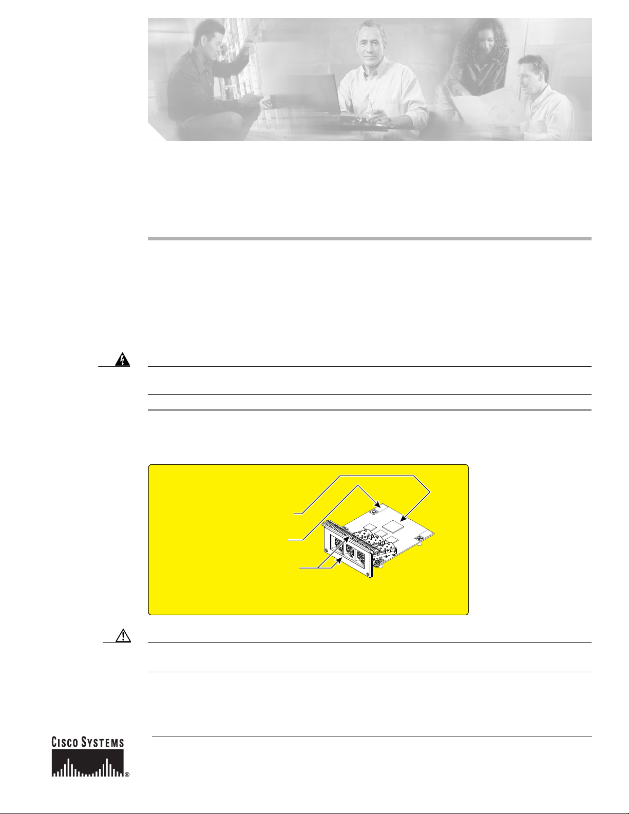
Step 1 First, read the yellow caution label on the EPA. Figure 1 shows a sample of this caution label.
Figure 1 Locations of Labels and Reference Points on the EPA
ATTENTION:
USE CARE DURING INSTALLATION OF EPA CARD,
MIS-ALIGNMENT CAN CAUSE DAMAGE TO THE
CONNECTOR AT THE UNDERSIDE REAR OF THE PCB.
MAKE SURE THAT THE CONNECTOR IS FULLY
ENGAGED BY PUSHING DOWN ON THE 2X LABELS
BEFORE INSTALLATION OF FRONT PANEL SCREWS (2X).
DO NOT APPLY EXCESSIVE FORCE TO THE FRONT
PANEL OR TOP SURFACE DURING INSTALLATION OR
DAMAGE CAN OCCUR TO THE PCB CONNECTOR.
149341
Caution The connectors must beengaged without any angular misalignment.Engagingthe connectors at anangle
will cause damage to the connectors.
Corporate Headquarters:
Cisco Systems, Inc., 170 West Tasman Drive, San Jose, CA 95134-1706 USA
Copyright © 2005 Cisco Systems, Inc. All rights reserved.
Page 2
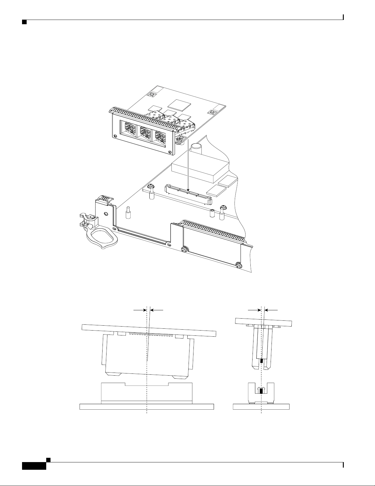
Step 2 Ensure that the connector guide pins are aligned, and mate the connector of the EPA to the connector on
the line card, as shown inFigure 2 and Figure 3. Figure 3 shows two sideviews of the EPA and linecard.
Figure 2 Mating the Connector of the EPA to the Line Card
PUSH
CORNERS
TO
INSTALL
PUSH
CORNERS
TO
INSTALL
129854
Figure 3 Side Views - Mating the Connector of the EPA to the Line Card
20˚ Max 4˚ Max
129857
Inserting an EPA into a Modular Gigabit Ethernet Line Card
2
78-17296-01 A0
Page 3
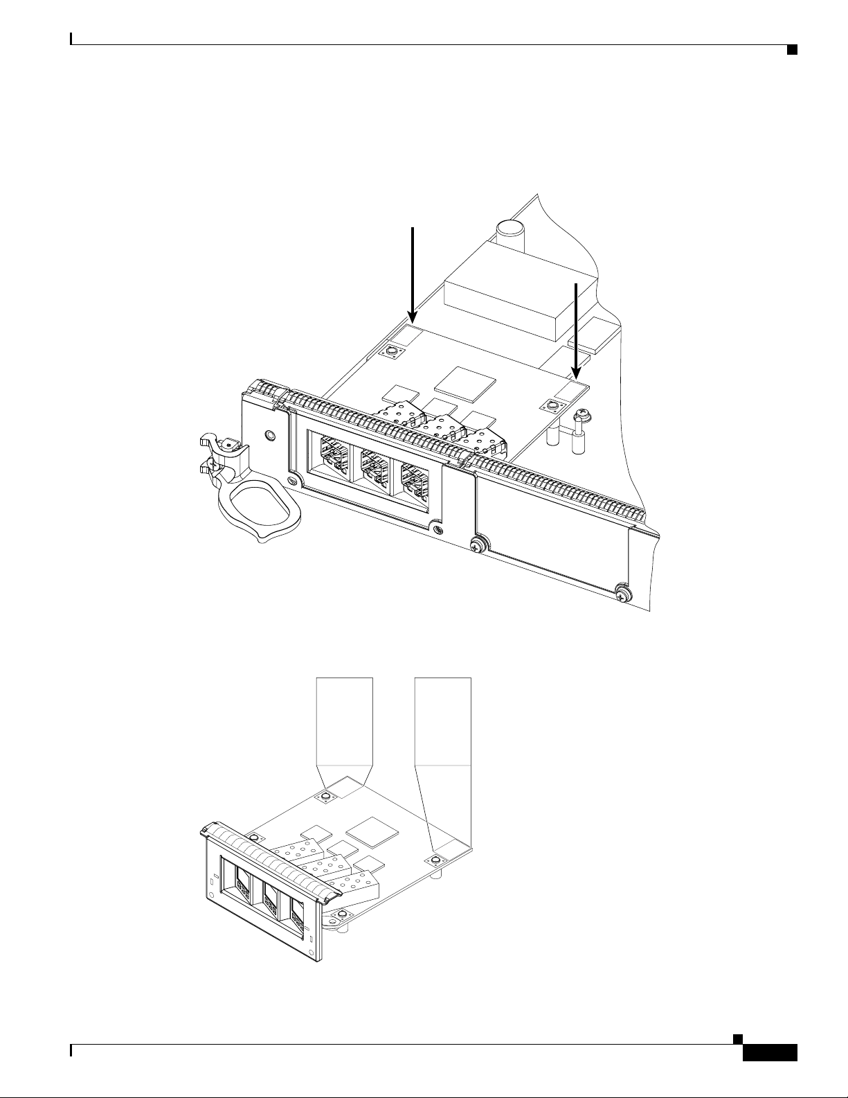
Step 3 Ensure that the connector guide pins are aligned. Once the connector is engaged, apply gentle pressure
with your thumbs to the two rear outer corners of the EPA, as shown in Figure 4 and Figure 5.
Figure 4 Press on the Rear Outer Corners of the EPA
PUSH
CORNERS
TO
INSTALL
PUSH
CORNERS
TO
INSTALL
Figure 5 Rear Outer Corners of the EPA (Close-up)
PUSH
BOTH
CORNERS
TO
INSTALL
PUSH
BOTH
CORNERS
TO
INSTALL
PUSH
BOTH
CORNERS
TO
INSTALL
PUSH
BOTH
CORNERS
TO
INSTALL
129765
129855
78-17296-01 A0
Inserting an EPA into a Modular Gigabit Ethernet Line Card
3
Page 4

Step 4 Press gently on the white labels in middle of the outer edge of the EPA as shown in Figure 6 to ensure
that the connector is fully seated.
Figure 6 Press on the White Labels on the EPA
PUSH
CORNERS
TO
INSTALL
PUSH
CORNERS
TO
INSTALL
129881
Inserting an EPA into a Modular Gigabit Ethernet Line Card
4
78-17296-01 A0
Page 5

Step 5 Use a Phillips screwdriver to insert and tighten the screwon the EPA, 3 to 5 in-lbs, as shown in Figure 7.
Caution Apply no more than 5 in-lbs of torque when tightening the screw.
Figure 7 Inserting and Tightening the Screw on the EPA
PUSH
CORNERS
TO
INSTALL
PUSH
CORNERS
TO
INSTALL
129875
78-17296-01 A0
Inserting an EPA into a Modular Gigabit Ethernet Line Card
5
Page 6

Step 6 Use a Phillips screwdriver to insert and tighten the two screws on the faceplate of the line card,
3 to 5 in-lbs, as shown in Figure 8.
Caution Apply no more than 5 in-lbs of torque when tightening the screw.
Figure 8 Inserting the 2 screws on the Faceplate of the Line Card
PUSH
CORNERS
TO
INSTALL
PUSH
CORNERS
TO
INSTALL
129856
Inserting an EPA into a Modular Gigabit Ethernet Line Card
6
78-17296-01 A0
Page 7

CCSP, CCVP, the Cisco Square Bridge logo, Follow Me Browsing, and StackWise are trademarks of Cisco Systems, Inc.; Changing the Way We
Work, Live, Play, and Learn, and iQuick Study are service marks of Cisco Systems, Inc.; and Access Registrar, Aironet, ASIST, BPX, Catalyst,
CCDA, CCDP, CCIE, CCIP, CCNA, CCNP, Cisco, the Cisco Certified Internetwork Expert logo, Cisco IOS, Cisco Press, Cisco Systems, Cisco
Systems Capital, the Cisco Systems logo, Cisco Unity, Empowering the Internet Generation, Enterprise/Solver, EtherChannel, EtherFast,
EtherSwitch, Fast Step, FormShare, GigaDrive, GigaStack, HomeLink, Internet Quotient, IOS, IP/TV, iQ Expertise, the iQ logo, iQ Net Readiness
Scorecard, LightStream, Linksys, MeetingPlace,MGX,theNetworkers logo, Networking Academy, Network Registrar, Packet, PIX, Post-Routing,
Pre-Routing, ProConnect, RateMUX, ScriptShare, SlideCast, SMARTnet, StrataView Plus, TeleRouter, The Fastest Way to Increase Your Internet
Quotient, and TransPath are registered trademarks of Cisco Systems, Inc. and/or its affiliates in the United States and certain other countries.
All other trademarks mentioned in this document or Website are the property of their respective owners. The use of the word partner does not imply
a partnership relationship between Cisco and any other company. (0502R)
© 2005 Cisco Systems, Inc. All rights reserved.
78-17296-01 A0
Inserting an EPA into a Modular Gigabit Ethernet Line Card
7
 Loading...