

Page 1

Cisco MGX 8230 Edge Concentrator
Installation and Configuration
Release 1.1.31
May 2001
Corpor ate Headquarters
Cisco Systems, Inc.
170 West Tasman Drive
San Jose, CA 95134-1706
USA
http://www.cisco.com
Tel: 408 526-4000
800 553-NETS (6387)
Fax: 408 526-4100
Customer Order Number: DOC-7811215=
Text Part Number: 78-11215-03 Rev. B0
Page 2

THE SPECIF ICA TIONS AND INF ORM AT IO N REGARDING TH E P ROD U CTS IN T HI S M AN UAL A R E S U BJE CT TO C H ANGE W ITH O UT
NOTICE. ALL STATEMENTS, INFORMATION, AND RECOMMENDATIONS IN THIS MANUAL ARE BELIEVED TO BE ACCURATE BUT ARE
PRESENTED WITHOUT WARRANTY OF ANY KIND, EXPRESS OR IMPLIED. USERS MUST TAKE FULL RESPONSIBILITY FOR THEIR
APPLICATION OF ANY PRODUCTS.
THE SOFTWARE LICENSE AND LIMITED WARRANTY FOR THE ACCOMPANYING PRODUCT ARE SET FORTH IN THE INFORMATION
PACKET THAT SHIPPED WITH THE PRODUCT AND ARE INCORPORATED HEREIN BY THIS REFERENCE. IF YOU ARE UNABLE TO
LOCATE THE SOFTWARE LICENSE OR LIMITED WARRANTY, CONTACT YOUR CISCO REPRESENTATIVE FOR A COPY.
The following informati on is for F CC compli an ce of Class A device s: This eq uipment has been teste d and found t o co mply wit h the limits for a Class A
digital device, pursuant to pa rt 15 of th e FCC rul es. Thes e limits ar e design ed to prov ide re asona ble prote cti on agai nst harmf ul i nt erferenc e when the
equipment is operated in a commercial environment. This equipment generates, uses, and can radiate radio-frequency energy and, if not installed and used
in accordance with the inst ruction ma nua l, may ca use harmf ul interfer ence to ra dio com muni cations. Oper atio n of this e quipme nt in a resident i al area is
likely to cause harmful interfe rence , in whi ch case users will be require d to corr ect the int erfer ence a t their own expen se.
The following information is for FCC compliance of Class B devices: The equipment described in this manual generates and may rad i at e radio-fre q uency
energy. If it is not installed i n accor dance wi th Cisco’ s install ati on ins tructi ons, it may caus e interfere nce wit h ra dio and telev ision re cept ion. T his
equipmen t has bee n teste d and fo und to co mply with the limits f or a Cla ss B di gital device in acco rdan ce with th e spec ific atio ns in part 15 of the FCC rules.
These specifications are designed to provi de reason able pr otec tion agains t su ch interf erenc e in a resid ential installati on. Ho we ver, there i s no gu a r an tee
that interference will not occur in a particular installation.
Modifying the equipment wit hout C isco’s w ritten authoriza tion may r esult in the e quipme nt no longer c omplyi ng with F CC requ irements for Class A or
Class B digital devices. In tha t event, your right to use the equipme nt may be limited by FCC re gulati ons, and you may be re quired to correct any
interference to radio or tele vision c ommun icati ons at your o wn e xpense.
You can determine whether your equipment is causing interference by turning it off. If the interference stops, it was probably caused by the Cisco equipment
or one of its peripheral devices. If the equi pment caus es int erferenc e to rad io or televi sion recepti on, try to correc t the inte r fe rence by using one or more
of the following measures :
• Turn the television or radio ant enna unt il the int erferenc e st ops.
• Move the equipment to one side or the ot her of the tel evisi on or radi o.
• Move the equipment farther awa y fr om the televi sion or ra dio.
• Plug the equipment into an outlet that is on a different circuit from the television or radio. (That is, make certain the equipment and the television or radio
are on circuits controlled by diff erent circ uit break ers or fuses.)
Modifications to this produc t not aut horized by C is co Systems, Inc. cou ld void t he FCC approva l and ne gate your a uth ority to operate the product.
The Cisco implementation of TCP header compression is an adaptation of a program developed by the University of California, Berkeley (UCB) as part of
UCB’s public domain version of t he UNIX oper atin g system. All rig hts reser ved. Copy ri ght © 1981 , Regen ts of the Unive rsi ty of Cal iforni a.
NOTWITHS TA NDI NG AN Y OT HER WARR AN TY HE REI N, ALL D OCUM ENT F IL ES AND SOF TWA R E OF TH ES E SU PPLIE RS A RE PR O VIDE D
“AS IS” WITH ALL FAULTS. CISCO AND THE ABOVE-NAMED SUPPLIERS DISCLAIM ALL WARRANTIES, EXPRESSED OR IMPLIED,
INCLUDING, WITHOUT LIMITATION, THOSE OF MERCHANTABILITY, FITNESS FOR A PARTICULAR PURPOSE AND
NONINF R I NGEMEN T OR A R IS I N G F R O M A COURS E OF DEALI N G, U S AGE, OR T RADE PRA C TIC E.
IN NO EVENT SHALL CISCO OR ITS SUPPLIERS BE LIABLE FOR ANY INDIRECT, SPECIAL, CONSEQUENTIAL, OR INCIDENTAL
DAMAGES, INCL UD IN G , WI TH OU T LI MITATION, LO ST P R OFIT S OR LO S S O R DA M AG E TO DATA ARISING OU T O F TH E USE OR
INABILITY TO USE THIS MANUAL, EVEN IF CISCO OR ITS SUPPLIERS HAVE BEEN ADVISED OF THE POSSIBILITY OF SUCH DAMAGES.
AccessPath, AtmDirector, Browse with Me, CCDA, CCDE, CCDP, CCIE, CCNA, CCNP, CCSI, CD-PAC, CiscoLink, the Cisco NetWorks logo, the Cisco
Powered Network logo, Cisco Systems Networking Academy, the Cisco Systems Networking Academy logo, Fast Step, Follow Me Browsing, FormShare,
FrameShare, GigaStack , IGX, Int ernet Quo tien t, IP/VC, i Q Break through, iQ E xpertise, i Q Fa stTrack, the iQ Lo go, iQ Net Readine ss Scorecard, MGX,
the Networkers logo, Packet, RateMUX, S criptBui lder, Scr ip tShare, Sl ideCast, SMAR Tnet, TransP a th, Unity, V oice LAN, Wavel ength Route r, and
WebViewer are trademarks of Cisco Sys tems, In c.; Ch anging the Way We Work, Li ve, Play, a nd Learn , Discove r All That’ s Possibl e, and Empo weri ng
the Internet Generation, are service marks of Cisco Systems, Inc.; and Aironet, ASIST, BPX, Catalyst, Cisco, the Cisco Certified Inte r ne tw o rk E xp e rt lo go,
Cisco IOS, the Cisco IOS logo, Ci sco Syst ems, Ci sco Syst ems Ca pita l, the Cisco Sys tem s logo, E nterpr ise/Sol ver, EtherC hannel , EtherSwitch, FastHub,
FastSwitch, IOS, IP/TV, Li ghtStre am, MICA , Ne twork Regi strar, P IX, Post-Routi ng, P re-Rout ing , Regis trar, StrataView Plus, Stratm, S witchProbe,
TeleRouter, and VCO are regis tered tr adema rks of Ci sco Syst ems, In c. and /or its aff iliates in t he U. S. and cert ain other coun tries.
All other brands, names, or trademar ks menti oned in thi s docum ent or We b site are the propert y of the ir respe ctive ow ners. The us e of t he word pa rtne r
does not imply a partnership rela tionshi p be tween Ci sco a nd any other co mpa ny. (0104R)
Cisco MGX 8230 Edge Concentrator In stall ation an d Configuration
Copyright © 2001, Cisco Systems , Inc .
All rights reserved.
Page 3

Cisco Reader Comment Card
General Information
1 Years of net w orking experience Years of experience with Cisco product s
2 I have these network types: LAN Backbone WAN
Other:
3 I have these Cisco products: Switches Routers
Other: Specify model(s)
4 I perform these types of tasks: H/W Install and/or Maintenance S/W Config
Network Management Other:
5 I use these types of documentation: H/W Install H/W Config S/W Config
Command Reference Quick Reference Release Not es Online Help
Other:
6 I access this information through: Cisco Connection Online (CCO) CD-ROM
Printed docs Other:
% %
7 Which method do you prefer?
8 I use the fo llowing three product features the most:
% %
Document Information
Document Title: Cisco MGX 8230 Edge Concentr ator Installation and Configuration
Part Number: 78-11215-03 Rev. B0 S/W Release: Release 1.1.31
On a scale of 1–5 (5 being the best) please let us know how we rate in the following areas:
The document was written at my
The information was accurate.
technical level of understanding.
The document was complete. The information I wanted was easy to find.
The information was wel l organized. The information I found was useful to my job.
Please comment on our lowest score(s):
Mailing Information
Company Name Date
Contact Name Job Title
Mailing Addres s
City State/Province ZIP/Postal Code
Country Phone ( ) Extension
Fax ( ) E-mail
Can we contact you further concerning our documentat ion? Yes No
You can also send us your comments by e-mail to bug-doc@cisco.com, or fax your comments to us at
(408)527-8089.
Page 4
BUSINESS REPLY MAIL
FIRST-CLASS MAIL PERMIT NO. 4631 SAN JOSE CA
POSTAGE WILL BE PAID BY ADDRESSEE
ATTN DOCUMENT RESOURCE CONNECTION
CISCO SYSTEMS INC
170 WEST TASMAN DRIVE
SAN JOSE CA 95134-9883
NO POSTAGE
NECESSARY
IF MAILED
IN THE
UNITED STATES
Page 5

Preface xxi
Audience xxi
Organization xxi
Related Documentation xxii
MGX 8230 Edge Concentrator, Release 1.0 Related Documentation xxii
Cisco WAN Manager, Release 10, Related Documentation xxiii
Cisco WAN Switching Software, Release 9.3 Related Documentation xxiii
Conventions xxiv
Obtaining Documentation xxv
World Wide Web xxv
Document ation C D-R OM xxv
Ordering Documentation xxv
Document ation Fe edb ack xxvi
CONTENTS
CHAPTER
Obtaining Technical Assistance xxvi
Cisco.com xxvi
Technical Assistance Center xxvii
Contacting TAC by Using the Cisco TAC Website xxvii
Contacting TAC by Telephone xxvii
1 Introducing the MGX 8230 1-1
MGX 8230 System Overview 1-2
The Applications of the MGX 8230 1-3
As a feeder 1-3
As a Stand-Alone Switch 1-3
Multiprotocol Label Switching (MPLS) 1-3
Consolidation of Cisco CPE Traffic 1-3
Multiservice Stand-alone Concentrator 1-3
Universal Edge Architecture 1-3
Standards-Based Conversion to ATM 1-4
MGX 8230 Enclosure and Power 1-4
Slot Numbering and Placement 1-4
Single Height and Double Height Slots 1-5
MGX 8230 Power System 1-6
Optional AC Power Supply 1-6
Release 1.1.31, Part Number 78-11215-03 Rev. B0, May 2001
Cisco MGX 8230 Edge Concentrator Installation and Configuration
v
Page 6

Contents
DC-Powered MGX 8230 1-7
Cooling System 1-8
MGX 8230 Architecture 1-9
Cell Bus 1-10
MGX 8230 Management 1-11
Summary of MGX 8230 Cards and Modules 1-12
Introduction to Core Card Sets and Service Modules 1-12
Processor Switching Module (PXM1) 1-12
User Interface Back Cards 1-13
Service Resource Module (SRM) 1-14
Frame Relay Service Modules (FRSM) 1-14
ATM UNI Service Modules (AUSM) 1-14
Circuit Emulation Service Modules (CESM) 1-15
Voice Service Modules (VISM) 1-15
Route Processor Module (RPM) 1-15
Redundancy for Service Modules 1-16
1:1 Redundancy 1-16
Hot Standby 1-16
1:N Redundancy 1-16
CHAPTER
2 Module and Service Descriptions 2-1
Processor Switching Module 2-1
PXM1 Features 2-2
PXM1 Illustration and LED Description 2-2
PXM1 User Interface Back Cards 2-3
PXM1-UI (standard) 2-3
PXM-UI-S3 (optional) 2-4
Making Extern al Cloc k Conne ctio ns 2-4
Stratum 4 clocking 2-4
Stratum 3 clocking 2-4
PXM1 Back Cards 2-5
PXM1 User Interface Back Cards 2-5
SMFLR-1-622 Back Card 2-7
SMFIR-1-622 Back Card 2-8
SMF-155 Back Card 2-9
BNC-2T3 Back Card 2-10
BNC-2E3 Back Card 2-11
Service Resource Module 2-12
Bit Error Rate Testing 2-12
vi
Cisco MGX 8230 Edge Concentrator Installation and Configuration
Release 1.1.31, Part Number 78-11215-03 Rev. B0, May 2001
Page 7

1:N Service Module Redundancy 2-12
Bulk Distribution Mode 2-12
Module Requirements with Bulk Distribution and Redundancy 2-13
Installation Requirements for the MGX-SRM-3T3/C 2-13
SRM Illustration and LED Indicators 2-13
ATM UNI Service Module (AUSM) 2-15
AUSM Features 2-15
Quality of Service (QoS) Management 2-15
Inverse Multiplexing 2-15
Physical Layer Features 2-16
AUSM Front Card Illustration and LED Description 2-17
Back Cards for the AUSM/B 2-18
Frame Relay Servic e Mod ule s 2-20
Features Common to All FRSMs 2-20
Data -L i n k Layer fea t ur e s 2-20
Frame Relay features 2-20
ATM FUNI features 2-21
Frame Forwarding Features 2-21
Redundancy for Frame Service Modules 2-22
Hot Standby 2-22
1:1 Redundancy 2-22
1:N Redundancy 2-22
Connection Types on the FRSM 2-22
Frame Relay-to-ATM Network Interworking 2-23
Frame Relay-to-ATM Service Interworking 2-24
Frame Forwarding 2-26
ATM Frame-to-User Network Interface 2-26
Types of Frame Servi ce Modul es 2-27
FRSMs for T1 and E1 Lines 2-27
FRSMs for T3 and E3 lines 2-32
FRSMs for Serial Connections 2-38
Circuit Emulation Service Modules 2-45
CESM for T1 and E1 lines 2-45
CESM T1 and E1 Features 2-45
CESM for T3 and E3 lines 2-50
Voice Service: The VISM 2-55
VISM Documentation 2-55
Summary of Features Supported with VISM 2.0.1 2-55
VISM Redundan cy 2-57
Card Combinations 2-57
Contents
Release 1.1.31, Part Number 78-11215-03 Rev. B0, May 2001
Cisco MGX 8230 Edge Concentrator Install ati on and Configuration
vii
Page 8

Contents
VISM Card Illustrations and LED Description 2-58
Route Processor Module (RPM) 2-61
RPM Documentation 2-61
CHAPTER
3 Site Preparation 3-1
Parts Checklist 3-1
Site Preparation 3-1
Regulatory Compliance and Safety Information 3-3
Safety Recommendations 3-3
Maintaining Safety with Electricity 3-3
Warning Definition 3-4
Product Dispo sal Warn ing 3-5
Lightning Activity Warning 3-7
Jewelry Removal Warning 3-8
Power Supply Warning 3-9
Power Supply Disconnection Warning 3-10
Power Disconnection Warning 3-11
Grounded Equipment Warning 3-12
Installation Warning 3-12
Class 1 Laser Product Warning 3-13
Laser Beam Warning 3-13
Seismic Conside r ations 3-14
CHAPTER
viii
Seismic Anch oring fo r a Cisco Rack 3-14
Power and Grounding 3-17
AC Power Circuit Breakers 3-17
DC Power Circuit Breakers 3-17
Electrical Power for AC-Powered Nodes 3-17
Electrical Power for a DC-Powered MGX 8230 3-17
Bonding and Grou ndin g 3-18
Wiring a Mixed Ground System with Redundant Supplies 3-18
Conductor Characteristics for Carrying Current and Ensuring L o w Voltage Dr ops 3-20
Using the Electrostatic Wrist Strap 3-21
Co-Locating Cisco Units in the Same Rack 3-21
Making the Frame Bonding (Ground) Connection 3-21
Making Cisco Cabin et Ground Co nne ctio ns 3-22
4 Enclosure Installation 4-1
Chapter Summ ary 4-1
Cisco MGX 8230 Edge Concentrator Installation and Configuration
Release 1.1.31, Part Number 78-11215-03 Rev. B0, May 2001
Page 9

Mechanical Lift Guidelines 4-1
Installing a Stand-Alone MGX 8230 4-2
Rack Mounting an MGX 8230 4-2
Prepare for Rack Installation 4-3
Rack Positioning 4-3
Bracket Place men t 4-3
Mounting Kits 4-4
Install the MGX 8230 Using a Mechanical Lift (Recommended) 4-6
Rack Mounting Procedures for 19-Inch Racks (Mechanical Lift) 4-6
Rack Mounting Procedures for 23-Inch Racks (Mechanical Lift) 4-6
Install the MGX 8230 Without a Mechanical Lift (Optional) 4-7
Prepare for Installation 4-7
Remove the Front Cards 4-7
Remove the Back Cards 4-8
Rack Mount the MGX 8230 chassis 4-8
Re-install the front cards 4-10
Re-install the bac k cards 4-10
Connecting Power for DC Systems 4-11
Connecting Power for AC Systems 4-14
Installing AC Power Supply Modules in the AC Power Supply Tray (optional) 4-15
Making the Connections to the AC Power Supply Module(s) 4-15
Install the Cable Manager 4-17
Power up the MGX 8230 4-18
Contents
CHAPTER
5 Configuring the MGX 8230 Shelf 5-1
Summary of Shelf-Level Tasks 5-1
User Interface Access Ports 5-2
Control Port 5-2
Ethernet Port 5-2
Maintenanc e Port 5-3
Other Ports 5-3
IP-Based Applications 5-3
MGX 8230 MGX to BPX Feeder 5-3
Initial MGX 8230 Bring-Up 5-3
Bringing Up an MGX 8230 PXM With No Run-time Firmware 5-4
Configuring N ode -Leve l Para meters 5-6
Resource Partitioning 5-6
Downloading Firmware to a Service Module 5-9
MGX 8230 CLI Configuration of a Feeder 5-10
Release 1.1.31, Part Number 78-11215-03 Rev. B0, May 2001
Cisco MGX 8230 Edge Concentrator Install ati on and Configuration
ix
Page 10

Contents
Configuring th e OC-3 Upl ink 5-10
Establishing the BPX 8600-to-BPX 8600 Series Segment 5-12
CiscoView Configuration of a Feeder 5-13
Selecting an MGX 8230 5-13
Specifying the Feeder Application 5-14
Activating a Physical Line for the Uplink 5-14
Configuring Lo gical Int erf aces for the Feeder 5-15
Configuring the Line as a Feeder Trunk 5-16
CHAPTER
6 Card and Service Configuration 6-1
Connections on a Feeder 6-1
Modifying the Resource Partitioning 6-1
Sequence of Config ur ation Tas ks 6-2
Rules for Adding Connections 6-2
Rules for Adding a DAX Connection 6-2
Rules for Adding Three-Segment Connections 6-3
The Processor Switching Module 6-5
Configuring Syn ch roniz at ion for the She lf 6-5
Clock Sources 6-5
Clock Source Types 6-6
Clock Source Configuration 6-6
Configurat ion Exam ple 6-6
Configuring PXM1 Card-Level Parameters, Lines, and Ports 6-7
Automatic Protection Switching on the PXM1 6-9
APS Requireme nt s 6-9
APS Configuration 6-9
Adding Connections on a PXM1 in a Stand-Alone Node 6-10
ATM Universal Service Module (AUSM) 6-14
Summary of AUSM Features 6-14
Configure the Card, Lines, and Ports 6-15
Configure Inverse Multiplexing 6-17
Adding and Configuring Connections on the AUSM/B 6-17
BPX 8600-to-BPX 8600 Segment 6-23
Frame Service Module Features 6-23
Summary of Frame Service Module Features 6-24
MGX-FRSM-2CT3 Features 6-25
MGX-FRSM-2T3E3 Features 6-25
MGX-FRSM-HS2 Features 6-26
MGX-FRSM-HS1/B Features 6-26
Cisco MGX 8230 Edge Concentrator Installation and Configuration
x
Release 1.1.31, Part Number 78-11215-03 Rev. B0, May 2001
Page 11

Eight-Port FRSM Features 6-27
Configuring Frame Relay Service 6-27
Configuring the FRSM Cards, Lines, and Ports 6-28
Adding a Frame Relay Connection 6-31
Establishing the BPX 8600-to-BPX 8600 Series Segment 6-36
Test Commands for the FRSMs 6-36
Support for Alarm Reportin g 6-37
Bit Error Rate Testing on an Unchannelized T3 or E3 FRSM 6-37
Circuit Emulation Service Module for T3 and E3 6-38
Features 6-38
Cell Delay Treatment 6-38
Error and Alarm Response 6-39
Configuring Service on a T3 or E3 CESM 6-39
Configuring the Card, Lines, and Ports 6-40
Adding and Modifying Connections 6-40
Bit Error Rate Testing on a T3 or E3 CESM 6-42
Contents
Eight-Port Circu it Emu lation Servic e Modu les 6-42
Structured Data Transfer 6-43
Unstructur ed Data Tr ansf er 6-43
Cell Delay Treatment 6-44
Redundancy Support for the Eight-Port CESM 6-44
Error and Alarm Response 6-44
Configuring Service on an Eight-Port CESM 6-45
Configuring the Card, Lines, and Ports 6-45
Configuring Bulk Distribution and Redundancy 6-46
Adding and Modifying Connections 6-47
Service Resource Module 6-49
Configuring Card and Line Parameters 6-49
Bulk Distribution for T1 Service 6-50
Redundancy Support by the MGX-SRM-3T3/C 6-51
Configuring Redundancy Through the Redundancy Bus 6-51
Configuring Redundancy Through the Distribution Bus 6-52
Bit Error Rate Testing Through an MGX-SRM-3T3 6-53
Pattern Test Options 6-55
Loopback Test Options 6-56
Online Diagnostics test 6-56
Automatic Switchover 6-56
Alarms 6-56
Log Files 6-57
Release 1.1.31, Part Number 78-11215-03 Rev. B0, May 2001
Cisco MGX 8230 Edge Concentrator Install ati on and Configuration
xi
Page 12

Contents
Commands to Operate the Online Diagnostics 6-57
DS3 Loopback Test 6-58
Loopback Tests 6-58
Configure Loopback on the Entire DS3 Line 6-58
Configure Loopback on All DS1s in a DS3 Line 6-59
Receive a Loopback Request 6-59
Configure Transmit FEAC Code 6-60
Configure DS3 for Sending Looped or Normal Data 6-60
Configure DS3 to Send Line Loopback 6-60
Configure DS3 for Sending Loopback Deactivation Request 6-61
Configure Receive Validation FEAC Code 6-61
Configuring FEAC Validation Criteria to be FEACCodes4Of5 6-61
Configure FEAC Validation Criteria to be FEACCodes8Of10 6-62
Negative Tests 6-62
Disable FEAC Cod es 6-62
Configure DS3 Loopback Codes from t he Standby PXM1 Card 6-63
APPENDIX
A Technical Specifications A-1
MGX 8230 Enclosure, Power, and Performance Specifications A-1
MGX 8230 Processor Switching Module Specifications A-3
AUSM/B-8T1E1 Interface Characteristics A-6
FRSM-2CT3 Specifications A-9
FRSM-2CT3 Framer A-10
FRSM-2CT3 Line Alarms A-10
FRSM-2T3E3 Specifications A-10
FRSM-2T3E3 T3 Line A-11
T3 Framer Level A-11
FRSM-2T3E3 E3 Line A-12
E3 Framer Level A-12
FRSM-2T3E3 Line Alarms A-12
Statistics and Counter Specifications A-12
FRSM-HS2 Sp ecif ication s A-12
Counters and Statistics for FRSM-2C T3, FRSM-2T3E3, and FRSM-HS2 A-14
FRSM-HS1/B X.21 A-16
Interfaces A-16
xii
FRSM-8T1 Specification A-17
FRSM-8E1 Specification A-20
Circuit Emulation Service Module for T1 Operation A-24
Cisco MGX 8230 Edge Concentrator Installation and Configuration
Release 1.1.31, Part Number 78-11215-03 Rev. B0, May 2001
Page 13

Circuit Emulation Service Module for E1 Operation A-25
Physical and Electrical Characteristics for Cards A-27
Electromagnetic Compatibility A-27
Conformance A-28
ATM UNI A-28
SONET/SDH A-29
Frame Relay A-29
Circuit Emulations Service A-29
Safety A-30
Environmental A-30
Contents
APPENDIX
GLOSSARY
B Cable Specifications B-1
T3 Trunk Cabling B-1
Frame Relay Cablin g B-2
T1 Cabling B-2
E1 Cabling B-3
SMB Connector B-3
12IN1-S4 V.35/X.21 Back Card B-4
HSSI Port Connectors B-5
DC Power Cabling B-6
AC Power Cabling B-7
Control and Clock Cabling B-7
Maintenance and Control Ports B-7
External Clock Input Cabling B-8
T1 Clock Cabling B-8
External Alarm Cabling B-8
INDEX
Release 1.1.31, Part Number 78-11215-03 Rev. B0, May 2001
Cisco MGX 8230 Edge Concentrator Install ati on and Configuration
xiii
Page 14

Contents
xiv
Cisco MGX 8230 Edge Concentrator Installation and Configuration
Release 1.1.31, Part Number 78-11215-03 Rev. B0, May 2001
Page 15

Figure 1-1 MGX 8230 with Door Attached 1-2
Figure 1-2 MGX 8230 Slot Placement 1-5
Figure 1-3 MGX 8230 Card Cage, Front View 1-6
Figure 1-4 AC Power Supply Module, Rear View 1-7
Figure 1-5 MGX 8230 DC Power Entry Module 1-8
Figure 1-6 MGX 8230 Fan Tray Assembly 1-9
Figure 1-7 MGX 8230 Architecture Simple Block Diagram 1-10
Figure 1-8 Cell Bus Distribution 1-11
Figure 2-1 PXM1 Front Card 2-3
Figure 2-2 User Interface Back Card (PXM1-UI) 2-5
Figure 2-3 User Interface Back Card (PXM-UI-S3): Stratum 3 Clocking 2-6
FIGURES
Figure 2-4 OC-12 Long-Reach Back Card (SMFLR-1-622/B) 2-7
Figure 2-5 OC-12 Intermediate-Reach Back Card (SMFIR-1-622/B) 2-8
Figure 2-6 OC-3 Four-P or t Back Ca rd (S M F- 1 5 5 / B ) 2-9
Figure 2-7 Two-port T3 Back Card (BNC-2T3) 2-10
Figure 2-8 Two-port E3 Back Card (BNC-2E3) 2-11
Figure 2-9 MGX-SRM-3T3/C Card Set 2-14
Figure 2-10 AUSM/B-8T1 or AUSM/B-8E1 Front Card 2-17
Figure 2-11 RJ-48 and SMB Back Cards for the MGX-AUSM-8T1E1/B 2-19
Figure 2-12 BPX 8620 Network with NIW Connections 2-23
Figure 2-13 BPX 8600 Series Network with SIW Connections 2-24
Figure 2-14 MGX-FRSM-8T1 2-30
Figure 2-15 RJ-48 and SMB Back Cards for the MGX-FRSM-8T1/E1 2-31
Figure 2-16 MGX-FRSM-2CT3 2-34
Figure 2-17 MGX-FRSM-2T3E3 2-35
Figure 2-18 BNC-2T3 2-36
Figure 2-19 BNC-2E3 2-37
Figure 2-20 MGX-FRSM-HS2 2-41
Figure 2-21 MGX-FRSM-HS1/B Front Card Faceplate 2-42
Figure 2-22 SCSI2-2HSSI 2-43
Figure 2-23 12IN1 S4 Back Card Faceplate 2-44
Cisco MGX 8230 Edge Concentrator Installation and Configuration
Release 1.1.31, Part Number 78-11215-03 Rev. B0, May 2001
xv
Page 16

Figures
Figure 2-24 Front Cards for the Eight-Port CESM 2-48
Figure 2-25 RJ-48 and SMB Back Cards for the MGX-CESM-8T1E1 2-49
Figure 2-26 CESM-T3/E3 Front Card 2-52
Figure 2-27 BNC-2T3 Back Card for the CESM-T3/E3 2-53
Figure 2-28 BNC-2E3 Back Card for the CESM-T3/E3 2-54
Figure 2-29 VISM Front Cards 2-59
Figure 2-30 VISM Back Cards 2-60
Figure 3-1 Stability Plate Dimensions 3-15
Figure 3-2 Installing a Cisco Cabinet Over the Stability Plate 3-16
Figure 3-3 Mixed Grounding System 3-19
Figure 3-4 Frame Bonding Connection in Cisco-Supplied Rack 3-23
Figure 4-1 MGX 8230 Mounting Rail Positions 4-3
Figure 4-2 MGX 8230 Chassis with Rear Mounting Brackets for 19-Inch Rack 4-5
Figure 4-3 MGX 8230 Chassis Front View with 19-Inch Mid-Mounting Bracket 4-5
Figure 4-4 Front Card Insertion/Extractor Lever 4-7
Figure 4-5 Front View of MGX 8230 with 23-Inch Mid-Mounting Brackets 4-9
Figure 4-6 Rear View of MGX 8230 with Two D C PEMs 4-11
Figure 4-7 Rear View of MGX 8230 with 1 DC PEM 4-12
Figure 4-8 DC Power Entry Module, Rear View 4-12
Figure 4-9 Polarities at MGX 8230 PEM Pluggable Terminal Block 4-13
Figure 4-10 Pluggable Terminal Bloc k on MGX 8230 PE M 4-13
Figure 4-11 Optional 1200 Watt AC Power Supply Module, Rear View 4-14
Figure 4-12 Rear View of MGX 8230 with Two Optional AC Power Supply Modules 4-16
Figure 4-13 Rear View of MGX 8230 with One AC Power Supply Module 4-17
Figure 4-14 Cable Management System on Rack-Mount MGX 8230 4-18
Figure 5-1 MGX 8230 MGX Feeder Application 5-3
Figure 6-1 Frame Relay Connection Through an MGX 8230/BPX Network 6-4
Figure B-1 RJ-48 Connectors B-3
xvi
Cisco MGX 8230 Edge Concentrator Installation and Configuration
Release 1.1.31, Part Number 78-11215-03 Rev. B0, May 2001
Page 17

Table 1 MGX 8230 Edge Concentrator Related Documentation xxii
Table 2 Cisco WAN Manager Release 10 Related Documentation xxiii
Table 3 Cisco WAN Switching Release 9.3 Related Documentation xxiii
Table 1-1 Cell Bus Distribution 1-11
Table 2-1 LED Indicators for the SRM-3T3/C 2-13
Table 2-2 Line Redundancy LED Indicators for the SRM-3T3/C 2-13
Table 2-3 Eight-Port AUSM/B LED Indicators 2-18
Table 2-4 Card Level LED Indicators for the FRSM T1/E1 2-28
Table 2-5 Line Level LED Indicators for the FRSM T1/E1 2-29
Table 2-6 Card Level LED Indicators for the FRSM-2T3E3 2-33
Table 2-7 Line Level LED Indicators for the FRSM-2T3E3 2-33
TABLES
Table 2-8 Card Level LED Indicators for the FRSM-HS1/B and the FRSM-HS2 2-39
Table 2-9 Line Level LED Indicators for the FRSM-HS1/B and the FRSM-HS2 2-39
Table 2-10 12IN1-S4 Back Card Cable Types 2-39
Table 2-11 Cabling and Clock Sources for the MGX-FRSM-HS1/B 2-39
Table 2-12 Cabling Types and Part Numbers X.21 and V.35 2-40
Table 2-13 LED Indicators for Eight-Port CESM 2-46
Table 2-14 LED Indicators for T3/E3 CESM 2-51
Table 2-15 LED Indicators for VISM 2-58
Table 3-1 Ground Point Descriptions for Mixed Grounding 3-19
Table 3-2 Wire Gauge for Current Loads Over Copper Wire Lengths 3-20
Table 3-3 Resistance for Each Gauge of Copper Wire 3-21
Table 6-1 Policing Definitions According to Policing and Connection Type 6-12
Table 6-2 Supported Lines Rates on the MGX-FRSM-HS1/B 6-28
Table 6-3 CESM Errors and Ala rms 6-39
Table 6-4 CESM Errors and Ala rms 6-44
Table 6-5 Pattern Test for AX-FRSM-8T1, AX-CESM-8T1, and MGX-FRSM-2CT3 6-54
Table 6-6 Loopback Test for AX-FRSM-8T1, AX-CESM-8T1, and MGX-FRSM-2CT3 6-54
Table 6-7 Pattern Test for AX-FRSM-8E1 and AX-CESM-8E1 6-54
Table 6-8 Loopback Test for AX-FRSM-8E1 and AX-CESM-8E1 6-54
Table 6-9 Pattern Test for MGX-AUSM-8T1 6-54
Cisco MGX 8230 Edge Concentrator Installation and Configuration
Release 1.1.31, Part Number 78-11215-03 Rev. B0, May 2001
xvii
Page 18

Tables
Table 6-10 Loopback Test for MGX-AUSM-8T1 6-55
Table 6-11 Pattern Test for MGX-AUSM-8E1 6-55
Table 6-12 Loopback Test for MGX-AUSM-8E1 6-55
Table A-1 Enclosure and Electrical Characteristics A-2
Table A-2 PXM Specifications A-3
Table A-3 Physical Characteristics of the AUSM/B-8T1E1 A-6
Table A-4 T1 Interface Characteristics A-6
Table A-5 E1 Interface Characteristics A-7
Table A-6 ATM Interface Characteristics A-7
Table A-7 AUSM/B-8T1E1 Statistics and Counters A-8
Table A-8 Frame Relay Interface Standards A-9
Table A-9 FRSM-2CT3 Front Card Physical Characteristics A-9
Table A-10 FRSM-2CT3 Line Level A-9
Table A-11 Frame Relay Interface Standards A-10
Table A-12 FRSM-2T3E3 Front Card Physical Characteristics A-11
Table A-13 T3 Line Level A-11
Table A-14 E3 Line Level A-12
Table A-15 Frame Relay Interface Standards A-13
Table A-16 FRSM-HS2 Physical Characteristics A-13
Table A-17 FRSM-HS2 Line Characteristics A-13
Table A-18 Counters per Line A-14
Table A-19 Service-Related Statistics A-14
Table A-20 ATM Cell-Related Statistic s A-15
Table A-21 Diagnostic-Related Statistics A-16
Table A-22 Troubleshooting Statistics A-16
Table A-23 General Card Specifica tio ns A-17
Table A-24 Frame Relay Service With T1 Lines A-17
Table A-25 System Interface A-18
Table A-26 List of Counters A-19
Table A-27 General Card Specifica tio ns A-20
Table A-28 Frame Relay Service With E1 Lines A-21
Table A-29 System Interface A-22
Table A-30 List of Counters A-23
Table A-31 CESM 8T1 Card Information A-24
Table A-32 CESM 8E1 Card Set Details A-25
Cisco MGX 8230 Edge Concentrator Installation and Configuration
xviii
Release 1.1.31, Part Number 78-11215-03 Rev. B0, May 2001
Page 19

Table A-33 Physical Characteristics and Power Consumption by Card A-27
Table A-34 Electromagnetic Compatibility and Immunity A-27
Table B-1 Trunk Cables B-1
Table B-2 T3 Connec tor Pin Ass ignm en ts B-1
Table B-3 RJ-48C T1/E1 Connector Pin Assignments B-2
Table B-4 E1 Trunk/Circuit Line Cabling Specification B-3
Table B-5 E1 Connec tor Pin Ass ignm en ts (unbalan ce d) B-3
Table B-6 12IN1-S4 cable types B-4
Table B-7 V.35 signa ls B-4
Table B-8 X.21 Signa ls B-5
Table B-9 Cable Part Numbers for MGX-FRSM-HS1/BV B-5
Table B-10 Pinouts for SCSI-II Connector B-5
Table B-11 DC Power Wiring B-6
Tables
Table B-12 AC Power Cables B-7
Table B-13 Maintenance and Control Port Cabling B-7
Table B-14 RJ-45 Maintenance and Control Port Pin Assignments B-8
Table B-15 7T1 Clock Cabling B-8
Table B-16 Exter nal Ala rm Cab ling B-8
Table B-17 Network Alarm Pin Assignments B-9
Release 1.1.31, Part Number 78-11215-03 Rev. B0, May 2001
Cisco MGX 8230 Edge Concentrator Installation and Configuration
xix
Page 20

Tables
xx
Cisco MGX 8230 Edge Concentrator Installation and Configuration
Release 1.1.31, Part Number 78-11215-03 Rev. B0, May 2001
Page 21

Audience
Preface
This prefa ce de s crib es t he o bj ect ives, aud ien ce, organizatio n, an d co nvention s o f th e
Cisco MGX 8230 Edge Concentrator Installation and Configuration Guide.
This publication is intended for the person who will do the physical installation of the MGX 8230. The
MGX 8230 i s ty pica lly c o- lo cat ed an d rac k-mo unt ed wi th eith er an IGX 8 400 or BP X se ries s wit ch . The
MGX 823 0 in s tal le r sh o ul d be fa m il iar w i th electronic cir c ui tr y an d wiring pract ices and h ave
experienc e as an electronic or electrom ech an ic al technician, as w el l as w it h th e C is c o IGX / BP X
switches .
Note This Cisco MGX 8230 Edge Concentrator Installation and Configuration covers the installation and
configuration f o r th e equipment . Th e co mm an d r efer en ce an d e rr o r co de s for t he M G X 8 23 0 ar e
described in the section “Related Documentation."
Warning
Installation of the equipment should be performed by trained service personnel.
Organization
This do cu m en t is o rga ni zed into the f o llow in g ch apters:
• Chapter 1, “Introducing the MGX 8230”
• Chapter 2, “Mo dule and S er v ice Descr i pt io ns ”
• Chapter 3, “Site Preparation”
• Chapter 4, “En closure I nstalla tion”
• Chapter 5, “Configuring the MGX 8230 Shelf”
• Chapter 6, “Car d and Ser vice Configu rati on”
Release 1.1.31, Part Number 78-11215-03 Rev. B0, May 2001
Cisco MGX 8230 Edge Concentrator Installation and Configuration
xxi
Page 22

Related D ocumentation
Related Documentat ion
The following Cisco publications contain additional information related to the operation of the Cisco
MGX 8230 Edge Concentrator.
MGX 8230 Edg e Concentrator, Release 1 . 0 Related Documen tat i on
The following table lists documentation that contains additional information related to the installation
and op er a t ion of t he MGX 82 3 0 E d ge Concentrato r.
Table 1 MGX 8230 Edge Concentrator Related Documentation
Documentation Description
Cisco MGX 8230 Edge Concentrator Installation
and Configuration, Release 1.1.31
DOC-7811215=
Cisco MGX 8230 Edge Concentrator Command
Reference, Release 1.1.31
Provides installa tio n in s t ru ct io ns fo r th e MG X 8 230 Edg e
Concentr at or.
Provides detailed inf or mation on th e g en e ra l co mm an d lin e i nt er fac e
commands.
Preface
DOC-7811211=
Cisco MGX 8230 Error Messages, Release 1.1.31
DOC-7811213=
WAN CiscoView for the MGX 8230 Edge
Concentrator, Release 1.1.31
DOC-7810617=
Provide s er ror mes sag e desc ri ptio ns a nd re cover y pro ce dur es.
Provide s ins tru cti ons for usi ng WA N Cisc oView for the MG X 82 30
Edge Con cen trator.
xxii
Cisco MGX 8230 Edge Concentrator Installation and Configuration
Release 1.1.31, Part Number 78-11215-03 Rev. B0, May 2001
Page 23

Preface
Cisco WAN Mana ger, Release 10, Related Documentation
The foll owing table lists the doc um entation fo r the Cisco WAN Manager (CWM) network management
system for Rele ase 10.
Table 2 Cisco WAN Manager Release 10 Related Documentation
Documentation Description
Cisco WAN Manager Installation for Solaris, Release 10
DOC-7810308=
Cisco WAN M a na ge r U s er’s Guide , Release 10
DOC-7810658=
Cisco WAN Manager SNMP Service Agent Guide, Release 10
DOC-7810786=
Cisco WAN Manager Database Interface G uide, Re lease 10
DOC-7810785=
Provides procedures for installing Release 10 of the CWM
network management system on Solaris syst ems.
Provides procedures for operating Release 10 of the CWM
network management system.
Provides in for matio n abou t the CW M Si mple Ne twor k
Managemen t Proto col Ser vice Age nt comp onents an d
capabilit ies .
Provides th e informati on t o gai n di r ect acc ess t o th e C W M
Informi x OnLine d a ta base tha t i s used to store in for m at io n
about th e e lements wit h in y ou r ne tw or k .
Related Documentation
Cisco WAN Switching Software, Release 9.3 Related Documentation
This table lists related documentation for the installation and operation of the Cisco WAN Switching
Software, Re lease 9.3 a nd associated eq ui p m en t i n a C is c o WAN switching n et wo r k.
Table 3 Cisco WAN Switching Release 9.3 Related Documentation
Documentation Description
Cisco BPX 8600 Series Installation and
Configuration, Release 9.3.10
DOC-7811603=
Cisco IGX 8400 Installation and Configuration
DOC-7810722=
Update to the IGX 8400 Installation and
Configuration, Release 9.3.10
DOC-7811029=
Cisco IGX 8400 Series Reference
DOC-7810706=
Cisco WAN Switching Command Reference,
Relea se 9. 3.05
DOC-7810703=
Update to the Cisco WAN Switching Command
Reference, Release 9.3.10
Provid e s a genera l d es criptio n and technica l details of the BPX
broadband switch.
Provides installation instructions for the IGX multiband switch.
Update for Release 9.3.1 0 to the Cisco IGX 8400 Installation and
Config ur ation manual.
Provid e s a genera l d es criptio n and technic al details of the IGX
multib an d s w it ch .
Provides detailed information on the general command line interface
comman ds.
Provides detailed information on updates to the command line interface
comman ds f o r fe at ures new to sw it ch s o ftwar e re lease 9.3.10 .
DOC-7811457=
Release 1.1.31, Part Number 78-11215-03 Rev. B0, May 2001
Cisco MGX 8230 Edge Concentrator Install ati on and Configuration
xxiii
Page 24

Conventions
Table 3 Cisco WAN Switching Release 9.3 Related Documentation
Documentation Description
Cisco WAN Switching SuperUser Command
Reference, Release 9.3.10
Provid es d etailed in for m a tio n o n the comm an d l in e in ter fa ce
comman ds r equiring S u pe rU ser a ccess autho ri zat io n
DOC-7810702=
Cisco M P L S C on t rolle r Softwa re C on fig ur at ion
Guide, Release 9.3.10
Provides information on a method for forwarding packets through a
network.
DOC-7811658=
Conventions
This publ ication uses t h e f ol lowin g co nventi ons t o c onvey instructions an d in fo r mat io n.
Command descriptions use these conventions:
• Commands and keywords are in boldface.
Preface
• Arguments for which you supply values are in italics.
• Requir ed c ommand argum e nt s ar e in s id e a ng l e b ra cke ts (< >) .
• Optional command arguments are in square brackets ([ ]).
• Alternative keywords are separated by vertical bars ( | ).
Examples u s e t hes e co nventions:
• Terminal sessio n s an d in for mation the sy s t em d is p l ay s ar e i n screen font.
• Information you enter is in boldface screen font.
• Nonpri nt ing ch ar act er s, s u ch a s p as swo rds, are in an g le b rack ets (< >) .
• Default responses to system p rompt s are in square brackets ([ ]).
xxiv
Cisco MGX 8230 Edge Concentrator Installation and Configuration
Release 1.1.31, Part Number 78-11215-03 Rev. B0, May 2001
Page 25

Preface
Obtaining Documentation
Notes, tips , cauti ons, an d warnin gs use the fo llowing conventions and symbo ls:
Note Means reader take note. Notes contain helpful suggestions or references to materials not contained
in this m an u al.
Timesaver Means the described action saves time. You can save time by performing the action described in the
paragraph.
Caution Means reader be careful. In this situatio n, yo u m i ght do so m et hing tha t c ou ld r e su lt in equ i pm e nt
damag e or los s of data .
Warning
This warning symbol means danger. You are i n a situation that could cause bodily i njury. Before
you work on any equipment, be aware of the hazards involved with elect rical circuitry and be
familiar with standard practices for preventing accidents.
Obtaining D ocumentation
The following sections provide sources for obtaining documentation from Cisco Systems.
World Wide Web
Yo u can access the most cur re nt C isco d o cumentatio n o n t h e World Wide Web at the f o ll owing sites:
• http://www.cisco.c om
• http://www-china.cisco.com
• http://www-europe.cisco.com
Documen t at i on CD-ROM
Cisco d oc umentatio n an d additio n al li ter ature are available in a C D - ROM pa c ka ge, which s h ip s
with your product. The Documentation CD-ROM is updated monthly and may be more current than
printe d documentation. The CD-ROM package is available as a single unit or as an annual subscr iption.
Orderi ng D ocum entation
Cisco documentation is available in the following ways:
• Registered Cisco Direct Customers can order Cisco Product documentation from the Networking
Products M a rk etP l ace :
http:/ /w w w.cisco.com/cgi- bin/order/order _r o ot.pl
Release 1.1.31, Part Number 78-11215-03 Rev. B0, May 2001
Cisco MGX 8230 Edge Concentrator Install ati on and Configuration
xxv
Page 26

Obtaining Technical Assistance
• Register ed Ci sco .co m use rs c a n or der th e Doc ume ntat io n CD-R O M t hrough t he on li ne Su bsc ripti on
Store:
http://www.cisco.com/go/subscription
• Nonregis t er ed C is co .c om u s er s can order documentati on t hro ug h a lo cal account r epresenta tive by
calling Cisco corporate headquarters (California, USA) at 408 526-7208 or, in North America, by
calling 800 553-NETS(6387).
Documentation Feedback
If you are reading Cisco product documentation on the World Wide Web, you can submit technical
comments electronically. Click Feedb a ck in the toolba r and s ele ct Documentation. After you complete
the form, click Submit to sen d it to Cisco .
You can e-mail yo ur com ments to bu g- doc@ci s co.com.
To submit your comments by mail, use the response card behind the front cover of your document, or
write to th e fo ll owi ng a dd r es s:
Attn Document Resource Connection
Cisco Systems, Inc.
170 West Tasman Drive
San Jose, CA 95134-9883
Preface
We appreciate your comments.
Obtaining Technical Assistance
Cisco p rovi des Cisco.com as a start in g po in t fo r all technica l assistan ce. Cu sto m e rs and partne rs c an
obtain doc ument ation, trouble shooti ng tip s, and samp le conf igura tio ns from onli ne tools . For Cisco.c om
registered users, additional troubleshooting tools are available from the TAC website.
Cisco.com
Cisco.com is the foundation of a suite of interactive, networked services that provides immediate, open
access to Cisco information and resources at anytime, from anywhere in the world. This highly
integrated Internet application is a powerful, easy-to-use tool for doing business with Cisco.
Cisco.com provides a broad range of features and services to help customers and partners streamline
busin ess pr oce sses and i mpro v e pr odu ct i vi ty. Through Cis co.c om, you ca n f in d in for mat ion a bou t C isco
and our netw ork ing s olut ion s, servi c es, an d prog rams . In addi tio n, you can resolv e technic al is su es with
online t ech ni ca l s u p por t, d ow nl oa d an d t est s o ft ware packages, an d o rder Cisco learning materials an d
merchan d ise. Valuable onli ne skill ass e ss men t, trainin g, an d cer ti fica tio n p ro g ra ms a re al s o availab le.
Customer s and pa rtners can self -regis ter on C isco.c om to obta in addi tional person alized i nformat ion and
services. Registered users can order products, check on the status of an order, access technical support,
and view be nefit s spe cific to thei r re lati on shi ps with Cisc o.
xxvi
To acces s C is c o. com, go to th e following w e bsite:
http:/ /w w w.cisco.com
Cisco MGX 8230 Edge Concentrator Installation and Configuration
Release 1.1.31, Part Number 78-11215-03 Rev. B0, May 2001
Page 27

Preface
Technical A ssi stance Cent er
The Cisco TAC website is available to all customers who need technical assistance with a Cisco product
or technology that is under warranty or covered by a maintenance contract.
Contact i ng TAC by U si ng the Cisco TAC Web si t e
If you have a priority level 3 (P3) or priority level 4 (P4) problem, contact TAC by going to the TAC
website:
http:/ /w w w.cisco.com/ta c
P3 and P4 level problems are defined as follows:
• P3—Y our net w ork pe rf orma nce i s d egr ad ed. Netw or k fun ctio nali t y i s noti cea bly im pair ed , b u t most
business operations continue.
• P4—Y ou ne ed inform at ion or assi sta nce on Cis co p rod uc t ca pabi li tie s, prod uct i nst a lla ti on, o r ba sic
product configuration.
In each o f th e a bov e ca ses , use the Ci sco TAC website to q ui ck ly find an sw er s to y o ur q ue s ti on s.
Obtaining Technical Assistance
To register for Cisco.com, go to the following website:
http:/ /w w w.cisco.com/regis t e r /
If you cann ot res olv e your te chni cal i ssue b y us ing t he TAC o nl ine res our ces, Ci sco. co m re gi ste red u ser s
can op en a case online by using the TAC Cas e O p e n to ol at the follow in g w e b site:
http:/ /w w w.cisco.com/ta c/caseopen
Contact ing TAC b y T elephone
If you have a priority level 1(P1) or priority level 2 (P2) problem, contact TAC by telephone and
immediate ly open a case . To obtain a dir ect ory of tol l- free number s fo r your c ou ntry, go to the following
website:
http:/ /w w w.cisco .com/warp /public /687/Directory /D ir TAC.shtml
P1 and P2 level problems are defined as follows:
• P1—Y our product ion network is down, causing a cr itical impa ct to business oper ations if se rvice is
not re s to r e d qu ickly. No wor karoun d is ava ila ble.
• P2—Your production network is severely degraded, affecting significant aspects of your business
operations. No workaround is available.
Release 1.1.31, Part Number 78-11215-03 Rev. B0, May 2001
Cisco MGX 8230 Edge Concentrator Install ati on and Configuration
xxvii
Page 28

Obtaining Technical Assistance
Preface
xxviii
Cisco MGX 8230 Edge Concentrator Installation and Configuration
Release 1.1.31, Part Number 78-11215-03 Rev. B0, May 2001
Page 29

CHAPTER
1
Introducing the MGX 8230
This chapter contains an introduction to the Cisco MGX 8230 Edge Concentrator including a summary
of product features and equipment.
This chapter con tains the f o ll owin g in f or mation:
• MGX 8230 System Overview, page 1-2
–
The Ap plicati on s o f the MGX 8230, page 1-3
–
Universal Ed ge Ar ch itecture, pa ge 1- 3
–
Standards-Based Conversion to ATM, page 1-4
–
MGX 8230 Enclosure and Power, page 1-4
–
MGX 82 30 Ma na gem en t, page 1-1 1
• Summary of MGX 8230 Cards and Modules, page 1-12
–
Processor Switching Module (PXM1), page 1-12
–
User Inter fac e B ac k C ar d s, p ag e 1 - 13
–
Service Resource Module (SRM), page 1-14
–
Frame Relay Service Modules (FRSM), page 1-14
–
ATM UNI Service Modules (AUSM), page 1-14
–
Circuit Emulation Service Modules (CESM), page 1-15
–
Voice Service Modu le s ( V ISM ) , p age 1-1 5
–
Route Processor Module (RPM), page 1-15
• Redundancy for Service Modules, page 1-16
For more detailed descriptions of the Service Modules, cards and services, please refer to Chapter 2,
“Module and Service Descriptions”
For additional descriptions of the MGX 8230 capabilities and specifications, refer to the Cisco document
MGX 8230 Edge Concentrator Overview.
Release 1.1.31, Part Number 78-11215-03 Rev. B0, May 2001
Cisco MGX 8230 Edge Concentrator Installation and Configuration
1-1
Page 30
MGX 8230 System Over view
MGX 8230 System Ov erview
The Cisco MGX ™ 8230 Edge Concentrator is a small footprint Multiservice Gateway specifically
designed for Service Providers with space and power constraints. The Cisco MGX 8230 offers cost
effective narrowband, voice, and IP services; and acts as a feeder shelf to Cisco BPX 8600 series, MGX
8850, and Cisco IGX 8400 series Multiservice Switches. The MGX supports the following services:
• IP VP Ns usi n g C isco IOS s oftw are- b as ed M PLS / lab el sw it ch in g.
• The f ull sui te of voice-over-IP, voice-over-ATM, and c apabilities w it h full in terwork in g.
• Frame Re lay se rvic es.
• High-density Point-to-Point Protocol (PPP) for Internet access and aggregation.
• Narrowband ATM for managed data, voice, and video services.
• Circui t Emu lat io n ( CE) fo r pr ivate lin e r ep la cem en t.
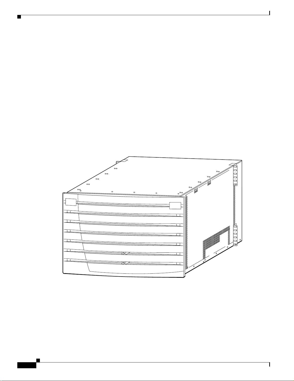
Figure 1-1 is an illustration of a MGX 8230 with its door attached. Note that there are light pipes in the
door that display the status of the processor models (PXM1s).
Figure 1-1 MGX 8230 with Door Attached
Chapter1 Introducing the MGX 8230
1-2
23823
Cisco MGX 8230 Edge Concentrator Installation and Configuration
Release 1.1.31, Part Number 78-11215-03 Rev. B0, May 2001
Page 31

Chapter1 Introducing the MGX 8230
The Applications of the MGX 8230
The MGX 8230 operates in the following applications:
Note Refe r to the Cis co document MGX 8230 Edge Conce ntrator Overview for addi tional information on
the applications of the MGX 8230.
Note See Chap te r 5, “Configuring the MGX 8230 Shelf” for information on configuring MGX8230
applications.
As a feeder
The MGX 8230 concentrates narrow-band and medium-band ATM, Frame Relay, and into a single,
wide-band ATM feeder t run k th at connects t o a B P X 86 0 0- se ri es sw i tch o r a M G X 88 50 sw it ch .
MGX 8230 System Overview
As a Stand-Alone Switch
The MGX 823 0 can be de ployed a s a stan d- a l on e s wi tch, prov iding “cross-conn ec t” connection s
between UNI and NNI ports. Traditionally, this would be used in a concentration-type mode, allowing
stand ar d s -b a sed adap tat i o n and conce n tr ation of m ul ti s e r vi ce tr affic on t o one or more hi gh-spee d ATM
inter fa ces . T hi s en ab le s th e MG X 823 0 to inte rf a ce to a m ul ti v e ndo r ATM netw ork , o r to an y oth er ATM
attached device (such as a Cisco 7200 or GSR router LS1010, MSR 8450, and so on).
The MGX 8230 interfaces to the ATM equipment using a standard ATM UNI or NNI..
Multiprotocol Label Switching (MPLS)
As a component of the BPX 8680-IP universal service node, the MGX 8230 is capable of forwarding
traffic into the BPX M P LS networ k by acting as a m u lt is e rv ic e f ee der
Consolidation of Cisco CPE Traffic
At the edge of the network, the MGX 8230 can interwork with and consolidate a wide variety of CPE
equipment.
Multiservice Stand-alone Concentrator
The MGX 8230 can be depl oyed as a stand-alone conce nt r ato r, in ter fa cin g to a multivend or ATM
(non-BPX) netw ork, as s hown Figure 1-5 . The MGX 82 30 inte rface s to ATM equipment us ing a st andard
ATM UNI or NNI.
Universal Edge Archit ecture
The MGX 8230 supports a wide range of services over narrowband and mid-band user interfaces by
mapping all service t r affi c to and from ATM using sta ndardized i nterworking methods. The MGX 8230
supports up to 64 channelized or non-channelized T1 and E1 interfaces on a single IP + ATM
multis er v ice gateway
Release 1.1.31, Part Number 78-11215-03 Rev. B0, May 2001
Cisco MGX 8230 Edge Concentrator Install ati on and Configuration
1-3
Page 32

MGX 8230 System Over view
The suppo rted i nt er faces fo r use r-tra ffic are:
• Frame Relay UNI o n T3, E3, HSS I , T 1, an d E1 li ne s .
• ATM UNI and FUNI interfaces.
• Optional inverse multiplexing for ATM (IMA).
• Frame Relay to ATM network interworking and service interworking.
• Circuit Emulation services for T1/E1 and T3/E3 lines.
The opti onal Se rvice R esource Module-3 T3 (MGX-S RM-3T3/ C) can su pport up to 64 T 1 inter face s. The
MGX-SRM-3T3/C can also provide 1:N redundancy for the T1 and E1 line cards.
The modul ar, sof t ware- b ased s y stem archi tec tu re en ab le s th e 8230 to su pp or t new f eat ur es through
downloadable software upgrades or new hardware modules.
The MGX 8230 backplane supports individual line rates range from DS0 through OC-3.
Standards-Based Conve r si on to ATM
The MGX 8 230 co nverts all u ser i nf o rma ti on i nto 53 - byte ATM cells by usi ng t he ap pro pr i ate ATM
Adaptat ion La yer ( AAL) for tra nsp ort ov er th e ATM backbone net wo rk. The indi v idua l se rvic e mod ules
segment an d r eassemble (SA R ) cel ls t o eli min ate system b o tt lenecks. The fo llow in g li st s h ows th e
applicab le AA L f or ea ch s erv ice:
Chapter1 Introducing the MGX 8230
• Circuit emulation services uses AAL1.
• Frame Relay-to-ATM network interworking uses AAL5 and Frame Relay Service Specific
Convergence Sub-layer (FR-SSCS).
• Frame Relay-to-ATM service interworking uses both transparent and translation modes to map
Frame Relay to native ATM AAL5.
• Frame Forwar ding uses A AL5.
MGX 8230 Enc l osure and Power
The MGX 8230 ha s a 14 single-height slot (7 double-height) chassis. Th is chassis can be rack mounted
in a 19-inc h rack, or fi tted wi th side panels to be a free-st anding bo x (referr ed to as a “stand-alone” MGX
8230). An optional mounting b r acket kit is also avail able for mounting the MGX 8230 in 23-inch racks.
Note Although the card slots in an MGX 8230 are horizontal, this manual refers to the card slots and
modules a s sin gl e-he ig ht an d do uble -he ight . This i s for co nsi ste nc y: t he P XM1 core card and s ervi ce
module ca rds a re a s u b set of t he M G X 8 25 0 car d s th at are ins tal le d ver tic all y in an MGX 82 50
chassis.
Slot Numbering and Placement
1-4
The MGX 8230 slots are populated with cards and modules according to the following rules
(Figure 1-2):
• The slots are numbered 1 to 7 on the left half of the chassis. The slots on the right side of the chassis
are numbered 8 to 14.
Cisco MGX 8230 Edge Concentrator Installation and Configuration
Release 1.1.31, Part Number 78-11215-03 Rev. B0, May 2001
Page 33

Chapter1 Introducing the MGX 8230
• Each s er vice module slo t can ac cep t one singl e- he ig ht ca rd o r b e converted to accep t two
double-height cards.
• Slots are 1 and 2 are always double-height slots and reserved for the primary and redundant MGX
8230 Processor Switch Modules (PXM1s).
• Slots 7 and 14 are reserved for SRM modules only: no other service modules can be used in these
two slots.
• Eight single-height slots (four double-height slots) are available for service modules.
Figure 1-2 is a conceptual drawing of an MGX 8230 showing the dimensions and the slot numbering.
The slot numbe ring is a s i t app ears f rom t he fro nt of the MGX 8 230; s lot s 8 a nd 9 refe r to b a ck card slo ts
only.
Single Height and Double Height Slots
Single-height slots on the MGX 8230 chassis can be converted into double-height slots.
• When a double-height front card is plugged in, the left slot number is used. The back cards are
numbere d accordin g to th e front card numbe ring sc heme, wi th the e xcept ion of sl ots 8 and 9 as noted
below.
• Since front slots 1 and 2 are always doubl e-height for PXM1 processor mo dules, slots 8 a nd 9 only
refer to t he bac k ca rd sl ot s that cor res pon d to th e t wo lo we r si ngle -he ight slo ts on the left sid e of the
chassis as s e en f rom th e r ea r.
MGX 8230 System Overview
• When co nverting si ng le -h ei gh t s lots in to d ou b le- h eig h t sl ot s t he co nversion m u st start fro m th e
bottom and be con ti guo us. For e xamp le, b efore y ou c an convert slot 4 i nto dou bl e he ig ht, sl ot 3 must
be converted fir st (as shown in Figure 1-3 on page 1-6).
Figure 1-2 MGX 8230 Slot Placement
(12.25 in.,
1 RU
(1.75 in.,
4.5 cm.)
7 RU
31.1 cm.)
7
6
F
A
5
N
4
T
R
3
A
Y
2
1
SRM
SM SM
SM SM
SM SM
SM
PXM 2
PXM 1
Optional AC power tray
17.72 in.
(45 cm.)
SRM
14
13
12
11
10
9
8
23.5 in.,
(59.7 cm.)
38375
Release 1.1.31, Part Number 78-11215-03 Rev. B0, May 2001
Cisco MGX 8230 Edge Concentrator Install ati on and Configuration
1-5
Page 34

MGX 8230 System Over view
Figure 1-3 MGX 8230 Card Cage, Front View
Chapter1 Introducing the MGX 8230
26268
Chapter 3, “Site Preparation” and Chapter 4, “Encl o sure Installation” contain additional information on
installing racks and the MGX 8 230 ch assis.
MGX 82 30 Power Sy stem
The MGX 823 0 p owe r s yst em i s d esi gn ed w it h dis tribu te d p ower ar ch it ect ure centered ar ou n d a
-48 VDC bus on the system backplane. The -48 VDC bus accepts redundant DC power from either a -42
to -56 VDC source via optional DC power entry modules (PEMs) or from a 100 to 120 or a 200 to 240
VAC source via the optional AC Power Supply Tray. The MGX 8230 backplane distributes power via
connectors on the - 4 8 VDC bu s to e a c h hot-pl ug gable p r ocessor or se rv ice mod ule. Each car d
incorpo rates on-boa rd D C -D C co nverter s to convert the -4 8 V DC f r om th e di s tr ibutio n bus vol tag e to
the voltag es r eq u ir ed o n th e card.
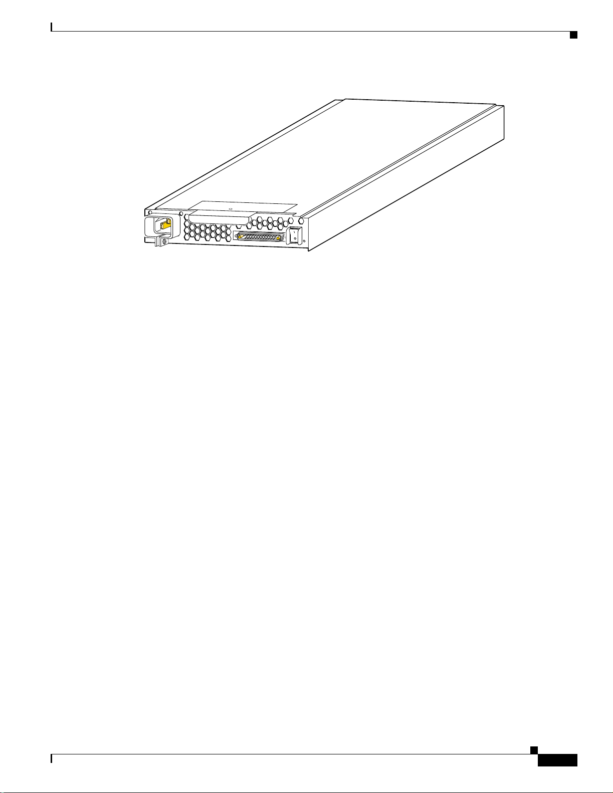
Optional AC Power Supply
For an AC-powered MGX 823 0, an opt i onal AC power suppl y tra y is a tt ach ed to the bo ttom of the MGX
8230 card cage at the f act or y. The AC power sup p ly tray i s o ne ra ck -un it hi g h, an d can h ol d up t o tw o
AC Power Supply modules. Each AC Power Supply module can provide up to 1,200W at -48 VDC an d
has it s own AC power cor d and power s w itch. Figure 1-4 shows the rear view of an optional AC Power
Supply modu le . Th e po we r supp lies c an be con f igure d as 1+1 re dun dant . If no redu ndancy is desired, an
AC tray with one AC power supply and one AC power cord can also be ordered.
1-6
Cisco MGX 8230 Edge Concentrator Installation and Configuration
Release 1.1.31, Part Number 78-11215-03 Rev. B0, May 2001
Page 35
Chapter1 Introducing the MGX 8230
Figure 1-4 AC Po w er Supply Module, Rear View
Each AC Power Supply Modu le inco rpora tes the follow ing feat ures:
• 1 rack unit high
• An output capacity of 1200 Watts at -48 VDC
• O-ring diode
AC
MGX 8230 System Overview
23818
DC
• EMI filtering
• Cooling fan
• Power switch
• DC and AC status LEDs
DC-Powe red MGX 8230
For DC syste ms, a DC Power E ntry modu le (PEM) is requ ired for eac h DC source of ce ntral of fi ce power
-42 to -56 VDC. The MGX 8230 can support two DC power sour ces and has rear panel slots for two DC
PEMS. Figure 1-5 illustrates a DC PEM.
The DC PEM s i nc orp orate the follow ing fe at ur es:
• Hot swappable
• O-ring diode
• EMI filtering
Release 1.1.31, Part Number 78-11215-03 Rev. B0, May 2001
Cisco MGX 8230 Edge Concentrator Install ati on and Configuration
1-7
Page 36

MGX 8230 System Over view
Figure 1-5 MGX 8230 DC Power Entry Module
Cooling System
The MGX 8 230 in co r po r at es a fan tray assem b l y ( with eight f an s) lo cat ed o n th e l ef t side of th e c ar d
cage to pull ambient cooling air into the system through openings between front card faceplates, over
the boards in the card cage, and out through air exhaust openings on the left side of unit. Figure 1-6 is
an illus trati on of the MGX 8230 f an tr ay ass embly . The coo ling sy stem in corpora tes th e follo win g desi gn
features:
48 VDC
30A
Chapter1 Introducing the MGX 8230
17275
TB1
1
2
3
OFF
• -48 VDC fans with rotation sensing
• N+1 fan redundancy
• Hot pluggable (if done quickly) Fan Tra y Assembly
• Noise level < 65 dBA
1-8
Cisco MGX 8230 Edge Concentrator Installation and Configuration
Release 1.1.31, Part Number 78-11215-03 Rev. B0, May 2001
Page 37

Chapter1 Introducing the MGX 8230
Figure 1-6 MGX 8230 Fan Tray Assembly
MGX 8230 System Overview
17274
MGX 8230 Arch i tecture
The MG X 8 23 0 ar ch it ecture is buil t around t he switch in g fabric on the processor sw i tch in g m o du le
(PXM1), t he ba ckpl ane, and the s ervi c e modul es. Figur e 1-7 is a very sim ple bloc k di agra m of t he MGX
8230 archite ctur e.
The main functions of the MGX 8230 backplane are to connect cards together, terminate critical signals
properly, provide -48 VDC power to all cards, and set ID numbers for each slot. In addition, the MGX
8230 backplane interconnects both front cards and back cards together via pass-through connectors. A
software re ad ab le ID o n th e backplan e i s available for sof twar e t o id en tif y th at the chas si s is a n
MGX 8230.
The cell bus controller s (CBCs) are applicatio n -sp ec ific in teg ra ted c ir cu it s ( A SIC s ) an d prov id e t he
interface be tw een the switching fa br ic an d th e s e rv i ce modules.
Release 1.1.31, Part Number 78-11215-03 Rev. B0, May 2001
Cisco MGX 8230 Edge Concentrator Install ati on and Configuration
1-9
Page 38

MGX 8230 System Over view
Figure 1-7 MGX 8230 Archit ecture Simple Block Diagram
Chapter1 Introducing the MGX 8230
Cell Bus
MGX 8230-PXM
front card
OC-3, OC-12,or
T3/E3 daughter card
Shared
memory
switch
Processor
CBC
CBC
PXM-UI
back card
PXM
uplink
back card
Cell buses
to and from
service modules
MGX 8230 midplane
Maintenance and
control ports
LAN ports
T1/E1 clocks
Alarm outputs
OC-3, OC-12,or
T3/E3 feeder link
38377
The MGX 8 230 cell bus (CB) p r ovide s h ig h-s p ee d i nt er fa ce b et w een t he sw it ch fab r ic an d th e s e rv ic e
modules.
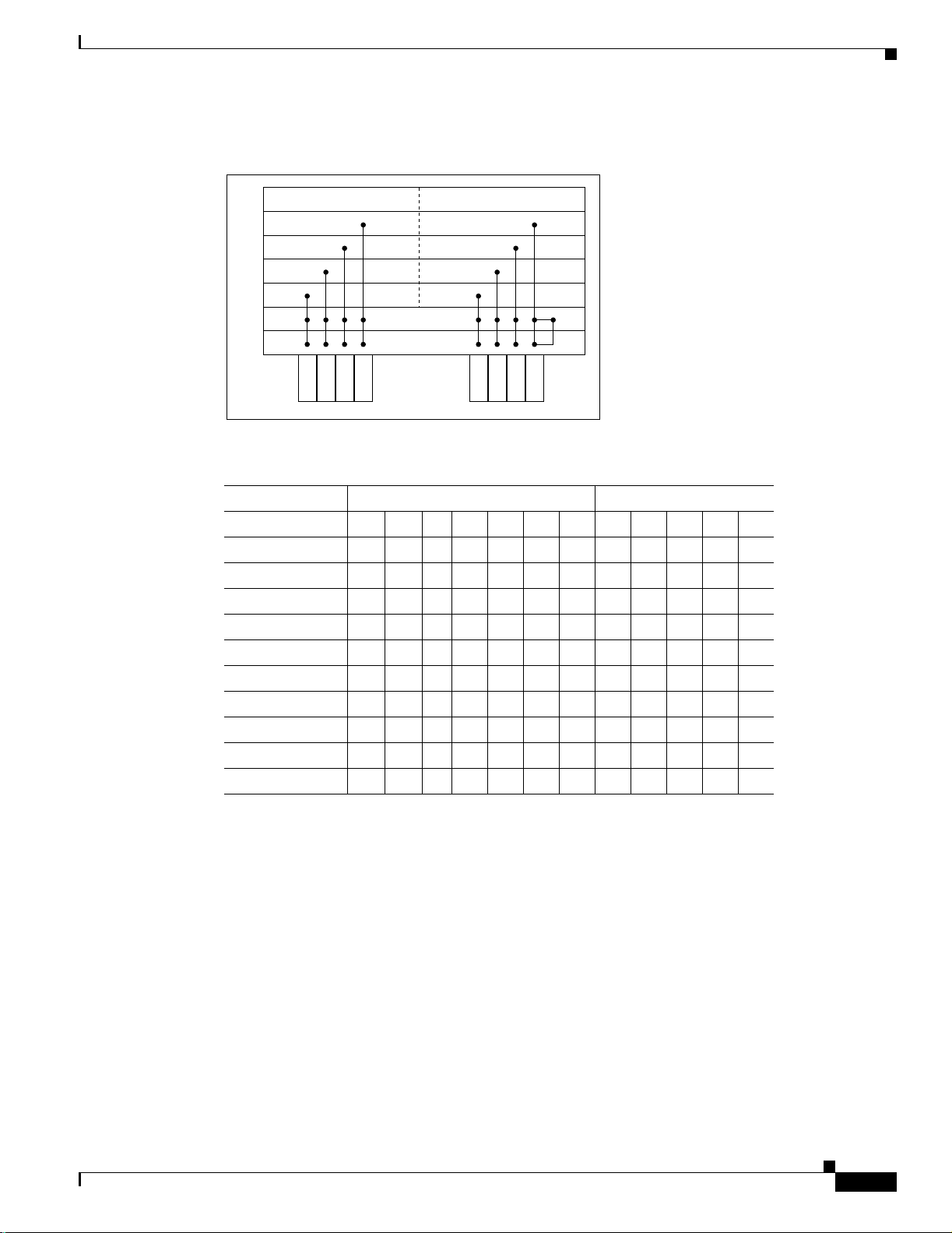
Figure 1-8 shows the overall cell bus distribution of MGX 8230 backplane and Table 1-1 lists the
specific c ell bu s al lo cat io n to each slot wi th re sp ec t to master an d s lave c ell bus po r ts.
Each PXM1 supports eight master cell buses and one slave cell bus connected to the backplane. The
service modules have two slave cell bus ports, one from each PXM1. The master cell bus ports are CB0
to CB7 and the PXM1 slave ports are referred to as 7S and 8S in Table 1-1.
A cell bus compr ises th e g rou p of sig na ls used to transfer da ta be tw ee n th e P X M and a serv ice module.
CB 0, 6, 1, 2, 4, and 3 are dedicated service modules, CB5 supports physical slot 6. CB7 supports
physical s l ot 1 3 as w el l as the alt er n ate P X M 1’s slave port.
There is a connectio n o n c ell bu s 7 to t he alternate P X M 1. A P XM 1 is a bl e t o c ommunicat e w i th th e
other PXM1 using the slave cell bus port on that card. Slots 8 and 9 only refer to back card slots.
1-10
Cisco MGX 8230 Edge Concentrator Installation and Configuration
Release 1.1.31, Part Number 78-11215-03 Rev. B0, May 2001
Page 39
Chapter1 Introducing the MGX 8230
Figure 1-8 Cell Bus Distribution
MGX 8230 System Overview
Left side of chassis Right side of chassis
CB3
14
13
12
11
10
9
8
CB7
38376
7
6
5
4
3
2
1
CB0
CB6
CB1
Table 1-1 Cell Bus Distribution
PXM
PXM
CB5
CB2
CB4
Left Side Chassis Right Side Chassis
Physical Slot #12345671011121314
Slot ID Address 1s 2s 9 A B C D 9 A B C D
CB0_A/B x
CB1_A/B x
CB2_A/B x
CB3_A/B x
CB4_A/B x
CB5_A/B x
CB6_A/B x
CB7_A x x
CB7_B x x
MGX 8230 Manag eme nt
Firmware on each card determines the functions and operations of the module. This firmware can be
upgra ded by dow nloading new firmware with a TF TP applicati on runnin g on a wor kstatio n or a P C.
The current status and configuration parameters of the modules reside in a Management Information
Base (MIB). The MIB is updated by the firmware in the modules whenever changes to the module status
or configuration occur. The MIB can be interrogated using SNMP commands.
The MGX 8230 supports the following user interface applications:
• Cisco WAN Manager (formerly StrataVie w Pl us ): a Graphical User Interf ac e (GUI) application for
connecti on ma nagement. Th is a pp li cat io n en ab le s op erat io n s , ad mi ni s trat io n, an d m ai nt en an ce of
WA N-m ul ti ser vice netwo rks .
• Cisc o View: a G U I application f o r hardware co n figuratio n.
Release 1.1.31, Part Number 78-11215-03 Rev. B0, May 2001
Cisco MGX 8230 Edge Concentrator Install ati on and Configuration
1-11
Page 40

Summary of MGX 8230 Cards and Modules
• Command line in ter fa ce ( CLI): th e CL I i s us e d f or low - level co n tr ol of hardw ar e f un ct io nality and
connecti on co n trol .
The followin g p orts ar e u sed t o c ommunicat e with the MG X 8 2 30:
• The Control port (SLIP protocol only) on the PXM1-UI back card.
• The L AN (E th er ne t) p ort on t he P X M 1-U I ba ck ca rd .
• The in-ban d ATM connect ion (fee der ap plicatio n only) .
All of the s e p o rts su pp o rt access by th e C LI v ia Telnet, TFTP, and SNMP.
Note See the User Interface Access Ports, page 5-2 for additional information on the ports used to manage
and configur e t he M G X 823 0.
Summary of MGX 8230 Cards and Modules
This section contains a summary of the service cards and modules supported by the MGX 8230.
Chapter1 Introducing the MGX 8230
For more d etailed des cr i ptions and ill us t ra ti ons of card s, m o du les and the s er v ice s th ey pr ov id e, please
refe r to Chapter 2, “Module and Service Descriptions”.
Introduction to Core Card Sets and Service Modules
The MGX 823 0 su ppo rts core cards and service modules. The Proces sor Swit chi ng M odule (PX M1) and
optiona l Service R eso ur ce M o du le (SRM) ar e core cards.
In addition, the PXM1 is part of a card set consisti ng o f a fr o nt card, a back ca r d, an d a d au gh te r car d :
• The fr ont card con tai ns th e p r oc es sin g in te lligence.
• The daughter card contains the firmware that distinguishes the interface (OC-3, T3, E3, and so on).
• The bac k c a rd is a s im pl e c ar d th at provides t he el ect ri cal i nt er face f or o n e o r mo r e li n es o f a
particular ty pe.
Service mo du le s ar e no t com bi ne d in this man n er an d ar e n ever pa rt o f a ca rd se t. Instead , servic e
modules provide the in terface for transport te ch no lo g ie s such as Frame Relay an d ATM.
The MGX 8230 enclosure contains up to 8 service modules (I/O cards). The optional Service
Redundancy Modules (SRMs) provide redundancy.
Note Although technically distinct, he terms card and module are often used intercha ngeably in the field.
Processor Switching Module (PXM1)
1-12
• Processor Switching Module (PXM1)
This front card controls the 8230 and supports external interfaces for user-access and trunking or
UNI ports. The back cards consist of a user interface card and a broadband network module.
Cisco MGX 8230 Edge Concentrator Installation and Configuration
Release 1.1.31, Part Number 78-11215-03 Rev. B0, May 2001
Page 41

Chapter1 Introducing the MGX 8230
User Int er f ace Back Ca r ds
• Proces sor Sw i tch M o d ul e U ser In ter fa ce (PX M 1 -U I)
The PXM1 -UI i s th e user inte rf a ce card that has various types of user access used to control and
configure the 8230.
• Processor Switch Module User Interface (PXM-UI-S3)
The PXM- U I-S3 is an op t iona l u ser in terf ace c ard that has various type s of user a ccess u sed to
control an d co nfi gur e t he 82 3 0. Th is car d al so p r ov id es S t ra tu m 3 cl oc ki ng c ap a b ili ty.
OC-3 Uplink Back Cards
• MGX-MMF-4-155/B (multi-mode fiber uplink back card)
The MGX-MMF-4-155/B is a broa dband ne tw ork module for the PXM1 and provides four SONET
OC-3/STM-1 ATM interfaces at 155 Mbps.
• MGX-SMFIR-4-155/B (single-mode fiber interm ediate reach up li nk back card)
The MGX-SMFIR-4-155/B is a broadband network module for the PXM1 and provides a
single -mode, intermediate-reach, f iber optic SONET OC-3 interface that conforms to ANS I T1.105
and GR-2 53 -CO R E s t an da rds . T hi s in t er fac e u ses SC connectors. Redundan t co nfigur ati on s are
supported through SONET automatic protection switching (APS) functionality (APS requires the
“B” model).
• MGX-SMFLR-4-155/B (single-mode fiber long reach uplink back card)
The MGX-SMFLR-4-155/B is a broadband network module for the P X M1 and p r ovides a
single-mode, long-reach, fiber optic SONET OC-3 interface that conforms to ANSI T1.105 and
GR-253-CO R E s t an da rds. Th is i nt erfac e u ses SC connectors, and redund an t co nfigu rati on s are
support ed through S O N ET A u to ma t ic P r o te ction Swit ch ing (APS) fu n ctionalit y ( A PS re quires th e
“B” model).
Summary of MGX 8230 Cards and Modules
OC-12 Uplink Back Cards
• MGX-SMFIR-1-622
The MGX-SMFIR-1-622 is a broadband network module for the PXM1 and provides a SONET
OC-12/STM-4 A TM interface at 622 Mbps. Automatic Protection Switching (APS) requires the “B”
model (SMFIR-1-622/B).
• MGX-SMFLR-1-622
The MGX-SMFLR-1-622 is a broadband network module for the PX M 1 and pr ovides a S O NET
OC-12/STM-4 A TM interface at 622 Mbps. Automatic Protection Switching (APS) requires the “B”
model (SMFLR-1-622/B).
T3/E3 Uplink Back Cards
• MGX-BNC-2T3
The MGX-BNC-2T3 is a broadband network module for the PXM1 and provides two T3 ATM
interface s .
• MGX-BNC-2E3
The MGX-BNC-2E3 is a broadband network module for the PXM1 and provides two E3 ATM
interface s. Two versio ns o f th e BN C - 2E3 c ar d ar e availa bl e. Th e BNC-2E3 A ap pl ies to Austr al ia
only. The BNC-2E3 applies to all other sites that require E3 lines on the PXM1 uplink card.
Release 1.1.31, Part Number 78-11215-03 Rev. B0, May 2001
Cisco MGX 8230 Edge Concentrator Install ati on and Configuration
1-13
Page 42

Summary of MGX 8230 Cards and Modules
Service Resource Modul e ( SRM)
• Service Resource Module (MGX-SRM-3T3/C)
The optional SRM provides three major functions for service modules; bit error rate tester (BERT)
of T1 a nd E1 l in es a nd por ts, loo ps bac k of i ndividual N x 64 c ha nnel s t o ward t he c ust ome r p remis es
equipment (CPE), and 1:N redundancy for the service modules.
Frame Relay Service Modules (FRSM)
• Frame Service Module for eight T1 ports (AX-FRSM-8T1)
The AX-F RSM - 8 T1 prov id es i n ter fa ces f o r up t o eig h t fractional T1 lines, each o f which can
support one 56 kbps or one Nx64 kbps FR-UNI, FR-NNI port, ATM-FUNI, or a Frame forwarding
port. Th e AX-F RSM-8T 1 sup por ts fr act io nal a nd unc hanne l ize d T1 po rt selec tio n on a per - T1 ba sis.
• Frame Service Module for eight E1 ports (AX-FRSM-8E1)
The AX-F RSM - 8 E1 prov id es i n ter fa ces f o r up t o eig h t fractional E1 lines, each o f which can
support one 56 kbps or one Nx64 kbps FR-UNI, FR-NNI, ATM-FUNI, or Frame forwarding port.
The AX-FRSM-8E1 supports fractional and unchannelized E1 port selection on a per-E1 basis.
• Frame Ser vice Mod ule for eig ht channelized T1 ports (AX-FRSM-8T1-C)
The AX-F RSM - 8 T1 -C al low s f ull D S 0 a nd n x D S0 ch an ne lization of th e T1 s. Each inte rface is
configurable as up to 24 ports running at full line rate, at 56 or n x 64 kbps for a maximum of 192
ports per FRSM-8T1-C.
Chapter1 Introducing the MGX 8230
• Frame Ser vice Mod ule for eig ht channelized E1 ports (AX-FRSM-8E1-C)
The AX-F RSM - 8 E1 -C al low s f ull D S 0 a nd n x D S0 ch an ne lization of th e E1 s. Each inte rface is
configurable as up to 31 ports running at full line rate, at 56 or n x 64 kbps for a maximum of 248
ports per FRSM-8E1-C.
• Frame Service Module for T3 and E3 (MGX-FRSM-2E3T3)
The MGX-FRSM-2E3/T3 provides interfaces for two T3 or E3 Frame Relay lines, each of which
can support either two T3 lines (each at 44.736 Mbps) or two E3 lines (each at 34.368Mbps)
FR-UNI, ATM-FUNI, or Frame Forwarding port.
• Frame Ser vice Mod ule for channelized T3 (MGX-FRSM-2CT3)
The MGX -F RSM-2CT3 su p po r ts i nt er fac es f o r two T3 channe lized Frame Relay lines . Eac h
interface supports 56 Kbps, 64 Kbps, Nx56 Kbps, Nx64 Kbps, T1 ports that can be freely distributed
across the tw o T3 lines .
• Frame Service Module for high speed serial (MGX-FRSM-HS1/B)
The FRSM-HS1 /B supports th e 12-in-1 back car d. This back card supports up to fo ur V.35 or X.25
serial int er fac es. This card a lso s u pp o rts th e tw o po r t HS S I b ack cards with S C S I-2 co n ne ctors.
• Frame Ser vice Mod ule for unch ann elized HSSI (MG X-FR SM-H S2/B )
The MGX -F RSM - H S 2/B supports in ter fa ces fo r tw o un ch an n eli zed H SS I l in es. Each interface
supports approximately 51 Mbps; with both lines operating, maximum throughput is 70 Mbps.
ATM UNI Service Modules (AUSM)
• ATM UNI Service Module for T1 (MGX-AUSM/B-8T1)
The MGX-A USM /B -8T1 pro v ides inte rf ace s for up to e ight T 1 lines. You can group N x T1 l ines to
form a sin g le, lo g ical interfac e ( IM A) .
1-14
• ATM UNI Service Module for E1 (MGX-AUSM/B-8E1)
The MGX-A USM /B -8E1 pro v ides inte rf ace s for up to e ight E 1 lines. You can group N x T1 l ines to
form a sin g le, lo g ical interfac e ( IM A) .
Cisco MGX 8230 Edge Concentrator Installation and Configuration
Release 1.1.31, Part Number 78-11215-03 Rev. B0, May 2001
Page 43

Chapter1 Introducing the MGX 8230
Circui t Emulatio n Service Modules ( CESM)
• Circuit Emulation Service Module for T1 (AX-CESM-8T1)
The AX-CESM-8T1 p rovi des in terfaces for u p to eight T1 li ne s , ea ch o f w hi ch is a 1 .5 44 M b ps
structured or unstructured synchronous data stream.
• Circuit Emulation Service Module for E1 (AX-CESM-8E1)
The AX-CESM-8E1 provides interfaces for up to eight E1 lines, each of which is a 2.048-Mbps
structured or unstructured synchronous data stream.
• Circuit Emulation Service Module for T3 and E3 (MGX-CESM-T3/E3)
The MGX-CESM-T3E3 provides direct connectivity to one T3 or E3 line for full-duplex
communic ati ons a t the DS3 ra te o f 44.73 6 MHz or at the E 3 rate of 34.36 8 MHz . Each T3 or E 3 l ine
consists of a pair of 75-ohm BNC coaxial connectors, one for transmit data and one for receive data,
along w ith three LED in dicato rs for li ne statu s .
Voice Service Modules (VISM)
• MGX-VISM-8T1 and MGX-VISM-8E1
These card s su pp o rt ei gh t T1 or E 1p o rts for t ra nsp o rtin g d ig iti zed vo ic e si gn al s ac ros s a pa cke t
network. The VISM provides toll-quality voice, fax and modem transmission and efficient
utiliz atio n o f wi de-a rea b andwi dt h t hrough in dust ry sta ndard imp lem enta ti ons of ec ho cance ll ati on,
voice-compression and silence- suppression techniques.
Summary of MGX 8230 Cards and Modules
Note For configuration information on the Voice Interworking Service Module (VISM), see the
Voice Interworking Service Module Installation and Configuration Guide
Route Pr ocessor Module (RPM)
• Route Processor Module (RPM)
The RPM is a C isco 7200 se ri es r o uter r ed esi gn ed as a double -hei gh t card . Each RPM use s tw o
single -height back cards. The back card types are single-port Fast Ethernet, four-port Ethernet, and
single-port (FDDI).
Note For information on availability and support of the MGX-RPM-128/B and MGX-RPM-PR,
see the Releas e N o tes fo r “Cisco WAN MGX 8850, 8230, and 8250 Software”
Note For configuration information on the Route Processor Module (RPM), see the Cisco Ro ut e
Processor Module Installation and Configuration Guide.
Release 1.1.31, Part Number 78-11215-03 Rev. B0, May 2001
Cisco MGX 8230 Edge Concentrator Install ati on and Configuration
1-15
Page 44

Summary of MGX 8230 Cards and Modules
Redundancy f or Service Modul es
Service modules can have either 1:1 redundancy or 1:N redundancy.
Refer to the Ci scoView user documentatio n f o r in s tructions o n u s in g th e CiscoView appl ication to
configure redundancy.
1:1 Redundancy
For 1:1 redundancy, place the card sets in adjacent slots and connect the appropriate Y -cable to the paired
ports on th e active and stan d by car d s. A p pl ica bl e service mod u les are:
• MGX-FRSM-2CT3
• MGX-FRSM-2T3E3
• MGX-FRSM-HS2
Hot Standby
For hot stan d by, place th e ca r d se ts i n th e s a me she lf an d co nn ec t t he approp riate Y- cable to th e p ai re d
ports on the active and hot stan dby card s. The hot stand by card wil l automa tical ly configur e itself to
match the configuration of the primary card. This process may take up to eight minutes. After the
configurati on tr an s f er pr o cess is complet ed , th e transfer fro m the primar y t o th e h o t sta nd by car d tak es
less that one second regardless of the number of connections. Any subsequent changes to the primary
card are au to matically tr ansferred t o the hot stan dby ca rd c on fig u ra tio n so th e two c a rds maintain t he
same co n figur at io n. Refer to th e “Redundancy for Service Modules” section on page 1-16 for
instructions for setting up a redundant pair.
Applicabl e ser v ic e m o d ul es a re :
Chapter1 Introducing the MGX 8230
1:N Redundancy
• MGX-FRSM-2CT3
• MGX-FRSM-2T3E3
• MGX-FRSM-HS2
To determine the ho t stand by s tatus of the sy ste m, use t he command dsphotstandby.
For 1:N redunda ncy, an MGX Service Resource Module-3T3 (MGX -S RM-3T3/C) c ard set is necessary.
This card set supports 1:N redundancy for the following service modules:
• MGX-AUSM-8T1/B
• MGX-AUSM-8E1/B
• AX-FRSM-8T1
• AX-FRSM-8E1
• AX-CESM-8T1
• AX-CESM-8E1
• MGX-VISM-8T1
• MGX-VISM-8E1
1-16
Cisco MGX 8230 Edge Concentrator Installation and Configuration
Release 1.1.31, Part Number 78-11215-03 Rev. B0, May 2001
Page 45

Chapter1 Introducing the MGX 8230
With 1:N redundancy, a group of service modules has one standby module. Redundancy by way of the
red undancy bus on the MGX- SRM-3T3/C require s the r edundan t card gr oup to h ave one of the foll owing
special back cards for redundancy support:
• R-RJ48-8T1-LM
• R-RJ48-8E1-LM
Summary of MGX 8230 Cards and Modules
Release 1.1.31, Part Number 78-11215-03 Rev. B0, May 2001
Cisco MGX 8230 Edge Concentrator Install ati on and Configuration
1-17
Page 46

Summary of MGX 8230 Cards and Modules
Chapter1 Introducing the MGX 8230
1-18
Cisco MGX 8230 Edge Concentrator Installation and Configuration
Release 1.1.31, Part Number 78-11215-03 Rev. B0, May 2001
Page 47

CHAPTER
2
Module and Service Descriptions
This chapter includes detailed descriptions of the modules, cards and services available with the
MGX 8230:
• Processor Switching Module, page 2-1.
• Service Resource Module, page 2-12.
• ATM UNI Service Module (AUSM), page 2-15.
• Frame Relay Service Modules, page 2-20.
• Circuit Emulation Service Modules, page 2-45.
• Vo ic e S e rv ic e: The VISM , p a g e 2 -55 .
Note Althoug h th e illustrati on s i n this cha pt e r d isp lay the eq u ip men t in a ver tic al po s i tio n , the cards an d
modules a r e rotated 90 degrees (to a horizo ntal position) when installed in t he MGX 8230 bac k card
slots. See the “MGX 8230 Enclosure and Power” section on page 1-4 for more information on slot
assign ments and module installation.
Processor Switchi ng Module
The PXM1 ca rd set co n s ist s of th e PXM 1 fro nt car d , th e PX M1 U ser Interface back ca rd (P XM 1 -U I or
PXM-UI-S3), and various uplink back cards th at can s e rve as either a trun k or a U NI.
For physical details of PXM1 cards, see Appendix A, “Technical Specifications.”
Caution Handle the PXM1 front card very carefully to preserve the alignment of the attached disk drive. Do
not dr o p or bu m p the PX M 1 .
Caution Before usi ng the 82 30, ve rify t hat th e daught er car d on the P XM1 corre sponds t o the uplink c ard typ e.
Serious damage may r es u lt if t he power i s o n a nd t he s e c ar ds ar e m i sm at ch ed .
Note The PXM1 processor module for the MGX 8230 is identical to the PXM1 for the MGX 8250.
Release 1.1.31, Part Number 78-11215-03 Rev. B0, May 2001
Cisco MGX 8230 Edge Concentrator Installation and Configuration
2-1
Page 48

Processor Sw itching Modu le
PXM1 Features
The PXM1 (Figure 2-1) is a combination ATM switching fabric, data processing, and ATM interface
card. Thi s mo du le co m b in es a 1 .2 G b ps s h ared - m emory swit ch in g fab r ic wi th i nt egr ate d tr un k in g at
speeds up to OC-12. The switching fabric provides 1.2 Gbps of non-b locking switching capacity, while
the pr ocessor provides t h e control p lane tha t delivers I P +ATM netwo r ki ng software, diagnos tics, an d
perfo rm anc e mo nito ri ng.
The PXM provides integrated switching, processing, and broadband interfaces to provide the following
high-performance switching and trunking features:
Chapter2 Module and Service Descriptions
• 1.2- Gb ps non- b lock ing swit ch ing
• Integrated T3/E3, OC-3c/STM-1, OC-12c/STM-16
• ATM trunking
• Linea r A ut omatic Pro tec ti on S witching fo r th e SONET i nt er fac es. Note that A P S i s availab l e f or
only t he “B” models of the OC-3 and OC-12 uplink cards.
• Hot card ins ertion/removal
• 1:1 ho t stan dby re du nda ncy
• User-selectable primary and secondary clock sources with graceful switchover
• Internal Stratum-4 or optional Stratum-3, external BITS, or inband clock sources
• Inband management or out-of-band via EIA/TIA-232 or 10BaseT control ports
• Narrowband service modules
• Broadband trunking support
• DSO to OC-12c/STM-4 interfaces supported
PXM1 Illustration and LED Description
PXM1 provides connectors for external audio and visual alarms. The interface can either be always open
or always closed. Major and minor alarms are controlled separately. An alarm cutoff button is accessible
from the front. A history LED is set when the alarm cutoff button is pressed. The history LED can be
cleared by p re s sin g th e h ist o ry cl ea r butt on o n th e f ace pl at e.
The PXM 1 p rov id es th e f o llow in g in d icators:
• System Status Active/Standby/Fail/standby update (green/yellow/red/flashing yellow)
• Critic al ala rm (bl ue)
• Major alarm (red)
• Minor alarm (yel low )
• DC OK A (green = OK, red = not OK)
2-2
• DC OK B (green = OK, red = not OK)
• ACO (green)
• History (g reen )
• Port act ivit y (a ctive a nd c lea r = g re en , r em o t e al ar m = yellow, local alar m = r ed )
• LAN activity ( fl a shing gr een)
Cisco MGX 8230 Edge Concentrator Installation and Configuration
Release 1.1.31, Part Number 78-11215-03 Rev. B0, May 2001
Page 49

Chapter2 Module and Service Descriptions
Figure 2-1 PXM1 Front Card
Processor Switch ing Module
PXM1 User Interface Back Cards
The PXM1 U ser I nt erfa ce ( PX M 1 -UI ) ba ck ca rd p rovi de s p orts for commu n ica ti on an d co n trol . T hi s
card is also used to connect the system to an external clocking source. Install this card in the upper half
of the back of the PXM1. See the “User Interface Acce ss Ports” section on page 5-2 for more informat ion
on the PX M 1 ba ck card p or ts .
There are tw o options for th e PX M 1 U ser I n ter fa ce b ac k car d :
PXM1-UI (standard)
11439
The PXM1-UI back card shown in Figure 2-2 provide s :
• One RJ-45/48 for external T1 or E1 clock input
• One BNC connector for E1 clock input
• One DB-15 female connector for alarm interface
Release 1.1.31, Part Number 78-11215-03 Rev. B0, May 2001
Cisco MGX 8230 Edge Concentrator Install ati on and Configuration
2-3
Page 50

Processor Sw itching Modu le
• Main tenance , Co ntrol an d L A N p or ts.
PXM-UI-S3 (optional)
The PXM- UI- S3 b ack ca rd s h own i n Figure 2-3 provides Stratum 3 clocking:
• One RJ-45/48 connector for external T1 or E1 clock input (CLK1).
• One DB-15 female con nector f or ala rm inte rface (A larm)
• Main tenance , Co ntrol an d L A N p or ts.
Note The LAN2 and CLK2 ports on the PXM-UI-S3 are not supported in this release. All external
connecti on s ar e m ad e with the LA N 1 an d CLK 1 p o rts .
Making Ext erna l Cl ock Connecti ons
If external eq ui p m en t o r a lo cal d ig ital centra l o ffice is to provide sy nc hr o ni zat io n , th e external cloc k
source is connected to t he P X M 1-U I o r PX M - U I-S 3 b ack c ar d.
Chapter2 Module and Service Descriptions
Stratum 4 clocking
Stratum 3 clocking
Note The LAN 2 a nd CLK2 po r ts on the PX M- U I -S 3 a re N OT sup p or te d in this re lease. All external
External cl ocki ng so ur ce s ar e connected t o th e P XM 1 -U I b ack card (Figure 2-2).
• One RJ-45/48 connector for external T1 or E1 clock input.
• One BNC connector for E1 clock input.
External cl ocki ng so ur ce s ar e connected t o th e P XM - U I-S 3 ba ck ca rd ( Figure 2-3).
• For T1 and E1 Stratum 3 external clock input, connect the source to the RJ-45/48 connector labeled
“CLK1.”
connecti on s ar e m ad e with the LA N 1 an d CLK 1 p o rts .
See Chap te r 5, “Configuring the MGX 8230 Shelf” for further information on configuring an external
clocking so ur ce.
2-4
Cisco MGX 8230 Edge Concentrator Installation and Configuration
Release 1.1.31, Part Number 78-11215-03 Rev. B0, May 2001
Page 51

Chapter2 Module and Service Descriptions
PXM1 Back Cards
This se cti o n contain s illustra tio n s o f th e f o llow in g PXM1 c ar ds.
• Figure 2-2: User In te rface Back Ca rd (PX M 1 -U I )
• Figure 2-3: Use r Interf ac e Back Car d (PXM- UI-S3 ): Stra t um 3 Clock ing
• Figure 2-4: OC-12 Long-Reach Back Card (SMFLR-1-622/B)
• Figure 2-5: OC-12 Intermediate-Reach Back Card (SMFIR-1-622/B)
• Figure 2-6: OC-3 Four-Port Back Card (SMF-155/B)
• Figure 2-7: Two-port T3 Back Card (BNC-2T3)
• Figure 2-8: Two-port E3 Back Card (BNC-2E3)
PXM1 User Interface Back Cards
Refe r to PXM1 U ser I nt erfac e B ack Cards, pag e 2 - 3 for descriptions of the features available with the
PXM1 User Interface b ack cards.
Processor Switch ing Module
Figure 2-2 User Interface Back Card (PXM1-UI)
PXM1-UI
T1
C
L
O
C
K
M
P
C
P
L
A
N
T1 clock
Maintenance port
Control port
LAN port
E1 clock source
E1 CLOCK
A
L
A
R
M
Alarm outputs
57659
Release 1.1.31, Part Number 78-11215-03 Rev. B0, May 2001
Cisco MGX 8230 Edge Concentrator Install ati on and Configuration
2-5
Page 52

Processor Sw itching Modu le
Figure 2-3 User Interface Back Card (PXM-UI-S3): Stratum 3 Clocking
C
P
M
P
L
A
N
1
L
A
N
2
PXM
UI-S3
EXT CLK 1
EXT CLK 2
Chapter2 Module and Service Descriptions
Control port
Maintenance port
LAN 1 port
LAN 2 port
(not supported in this release)
External Clock 1
(connection for T1 and E1
external clock sources)
External Clock 2
(not supported in this release)
Alarm Output Connection
Dry contact relay closures are available for forwarding MGX 8230 alarms to an alarm system. Separate
visual and audible alarm outputs are available for major and minor alarm outputs. The MGX 8230 alarm
outputs a r e availa bl e o n a D B - 15 c on ne ct or o n th e P X M - U I-S 3 b ack ca r d faceplate.
A
L
A
R
M
Alarm port
46010
2-6
Cisco MGX 8230 Edge Concentrator Installation and Configuration
Release 1.1.31, Part Number 78-11215-03 Rev. B0, May 2001
Page 53

Chapter2 Module and Service Descriptions
SMFLR-1-622 Back Card
An illustration of the long-reach OC-12 card appears in Figure 2-4. For specifications on this card, refer
to Ap pendix A, “Technical Speci fica tio n s.” Note that Automatic Protection Switching (APS) requires
the “B” model—an SMFLR-1-622/B.
Figure 2-4 OC-12 Long-Reach Back Card (SMFLR-1-622/B)
SMFLR-1-622
ENABLED
Processor Switch ing Module
SIGNAL
RX
TX
12210
Release 1.1.31, Part Number 78-11215-03 Rev. B0, May 2001
Cisco MGX 8230 Edge Concentrator Install ati on and Configuration
2-7
Page 54
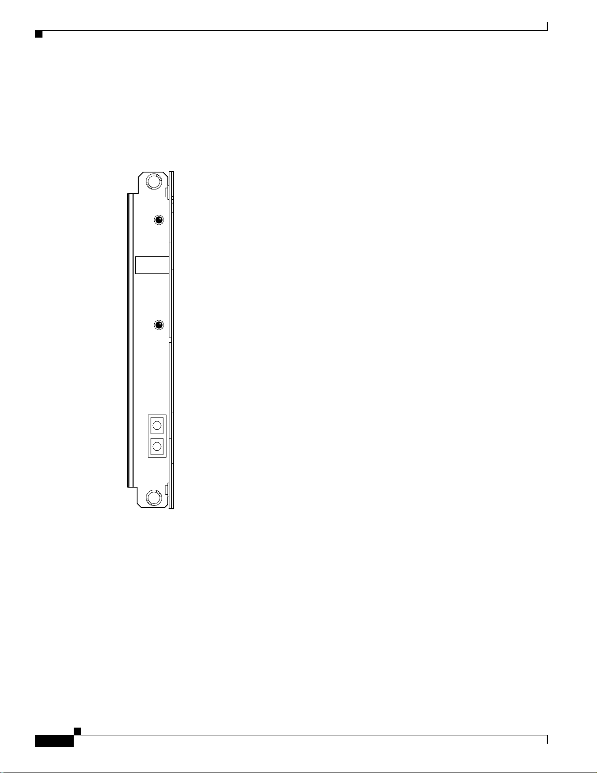
Processor Sw itching Modu le
SMFIR-1-622 Back Card
The intermediate-re ach O C-12 ba ck car d a pp ears in Figure 2-5. For sp e c i fi cation s on this c a r d , refer to
Appendix A, “Technical Spe cifi cat io ns.” Note th at Au to matic Protection Sw itching (A P S ) req ui r es th e
“B” model—an SMFIR-1-622/B.
Figure 2-5 OC-12 Intermediate-Reach Back Card (SMFIR-1-622/B)
SMFLR-1-622
ENABLED
Chapter2 Module and Service Descriptions
SIGNAL
RX
TX
12210
2-8
Cisco MGX 8230 Edge Concentrator Installation and Configuration
Release 1.1.31, Part Number 78-11215-03 Rev. B0, May 2001
Page 55

Chapter2 Module and Service Descriptions
SMF-155 Back Card
The SMF- 155 b ack card provid es a physical s i ngle-mode fibe r op ti c S ON ET OC-3 i nt erfac e t ha t
conform s to A N SI T1 .1 0 5 a nd G R - 253- C O RE s ta nd ar d s. Th is interface uses SC conn ec to r s , an d
redunda nt co n figur at io ns ar e s u p por ted through Y-cables. For sp ec ific at io ns on this card, refer t o
Appendix A, “Technical Spe cifi cat io ns.” Note th at Au to matic Protection Sw itching (A P S ) req ui r es th e
“B” model—an SMF-155/B.
Figure 2-6 OC-3 Four-Port Back Card (SMF-155/B)
SC-4-155
ENABLED
SIGNAL
RX
P
O
R
T
1
TX
SIGNAL
RX
P
O
R
T
2
TX
SIGNAL
RX
P
O
R
T
3
TX
SIGNAL
RX
P
O
R
T
4
TX
Processor Switch ing Module
12206
Release 1.1.31, Part Number 78-11215-03 Rev. B0, May 2001
Cisco MGX 8230 Edge Concentrator Install ati on and Configuration
2-9
Page 56

Processor Sw itching Modu le
BNC-2T3 Back Ca r d
For card sp eci fica tio n s, r ef er t o Appendix A, “Technical S pecific atio ns. ”
Figure 2-7 Two-port T3 Back Card (BNC-2T3)
Chapter2 Module and Service Descriptions
BNC-2T3
SIGNAL
RX
PORT 1
SIGNAL
PORT 2
TX
RX
TX
12209
2-10
Cisco MGX 8230 Edge Concentrator Installation and Configuration
Release 1.1.31, Part Number 78-11215-03 Rev. B0, May 2001
Page 57

Chapter2 Module and Service Descriptions
BNC-2E3 Back Ca r d
Two versions of the BNC-2E3 card are available. The BNC-2E3A applies to Australia only, and the
BNC-2E3 applies to all other sites that require E3 lines on the PXM1 uplink card. An illustration of the
two-port E3 b ack ca rd a pp ea rs in Figure 2-8. For specificati on s on this car d , r ef er t o Appendix A,
“Technical Speci fica ti ons .”
Figure 2-8 Two-port E3 Back Card (BNC-2E3)
BNC-2T3
SIGNAL
RX
Processor Switch ing Module
PORT 1
SIGNAL
PORT 2
TX
RX
TX
12209
Release 1.1.31, Part Number 78-11215-03 Rev. B0, May 2001
Cisco MGX 8230 Edge Concentrator Install ati on and Configuration
2-11
Page 58

Service R esource Module
Service Resource Module
A service resource module (SRM) provides three main functions for the service modules:
• Bit Erro r Rate Testing
• 1:N Service Module Redundancy
• Bulk Distribu tion Mo de
See Figure 2-9 for an illustration of the MGX-SRM-3T3/C front card and the MGX-BNC-3T3-M back
card.
Bit Error Rate Testing
After a service module line or port is put into loopback mode, the SRM can generate a test pattern over
the looped line or port, rea d the received looped data, and report on the error rate. This operation can be
performed on a comple te T1 or E1 li ne, on a fractional T1 or E1 line, on a SD0 bundle (N x DS 0), or on
a single DS0 channel. The SRM can support BERT only one line or channel at a time. BERT is capable
of generating a variety of test patterns, including all ones, all zeros, alternate one zero, double alternate
one zero, 223-1, 220-1, 215-1, 211-1, 29-1, 1 in 8, 1 in 24, DDS1, DDS2, DDS3, DDS4, and DDS5.
Chapter2 Module and Service Descriptions
1:N Service Module Redundancy
Service module redundancy provides 1:N redundancy for multiple groups of service modules (a
group consists of N active and one standby servi ce module). The r ed und an t s e rvice module in a
group mus t be a superset (wit h respect to functionality) of the car ds. Upon the detection of a failure
in any of the service modules, the packets destined for the failed service module are carried over the
CellBus to t he S RM i n it s ch ass i s. Th e S R M r eceives the pac kets an d s witches them to the backup
service m o du le v ia the Cel lB us.
Bulk Distribution Mode
Each of the T3 ports can be used to support up to 28 multiplexed T1 lines, which are distributed to T1
servic e mo d ule ports in th e switch. C al l e d bulk dist ri but ion, this feature is perform e d wh en the SRM is
in “bulk mode.” The purpose of this feature is to allow large numbers of T1 lines to be supported over
T3 line s r ath er t ha n over individ ua l T1 lines.
Any T1 c h annel in a T3 line can b e d is tributed to any e ig h t p o rt s e r v ice modu l e i n any slo t . Each
MGX 8230 shelf can support up to 64 T1 lines.
The SRM-3T3 can also be operated in “nonbulk mode” on a port-by-port basis. For a port configured in
nonbulk mode, bulk distribution is disabled and the SRM provides BERT and 1:N redundancy functions
only.
Linking the MGX-SRM-3T3/C to a destination card causes the switch to take CPE traffic through the
MGX-SR M -3T3 /C r ath er t ha n the T1 car d ’s line module. Linkage is a card-level condition. If you link
just one T1 channel on a service module to the MGX-SRM-3T3/C, the back card on the service module
becomes inopera tiv e, so you mus t link a ll othe r T1 port s on tha t ser vice m odule to the MG X-SRM-3T3/ C
if you wan t t h em t o oper at e.
2-12
Cisco MGX 8230 Edge Concentrator Installation and Configuration
Release 1.1.31, Part Number 78-11215-03 Rev. B0, May 2001
Page 59

Chapter2 Module and Service Descriptions
Module Requirements with B ulk D i stribu tion and Redundancy
The use of bu lk d istr i bution a ffec ts t he r eq ui re men ts for S R M an d ser vi ce m o du le ba ck ca rd s:
• With bulk distribution and 1:N redundancy support by way of the distribution bus, the service
modules do no t us e back cards.
• For just 1: N redundancy by way of t he redundancy bu s , the sup p or t e d servi ce m o dules must have
back cards —including one special redundancy back card. E1 redundancy requires the
AX-R-RJ48-8E or AX-R-SMB-8E1 line module, and T1 redundancy requires the R-RJ48-8T1 line
module.
• For bulk distribution, the T3 lines connect to an external multiplexer. The T1 lines on the other side
of the multiplexer connect to the CPE. The SRM converts the received traffic from its T3 lines to T1
channels an d s en d s th e da ta to lin ked service modules. For instructions on linking T1 channels and
card slots to the MGX-SRM-3T3/C, see Chapter 6, “Card and Service Configuration”
Installation Requirements for the MGX-SRM-3T3/C
The followin g ar e car d -l evel char ac ter istics that ap p ly to a ny SR M installa t io n:
Service Resource Module
• Only MGX-SRM-3T3/C cards can be installed in slots 7 and 14.
• No other service modules can be installed in slots 7 and 14. These slots do not have cell bus
connecti on s. The SRM m od u le s use a local bus to co m mu n ic ate with th e P X M .
• The PXM1 in slot 1 controls the SRM in slot 7. The PXM1 in slot 2 controlsthe SRM in slot 14.
• Either S RM in slot 7 o r 1 4 can b e a ctive ( d ep en ding o n th e active PXM1).
SRM Illustration and LED Indicators
Table 2-1 and Table 2-2 describe the SRM-3T3 LED faceplate indicators.
Table 2-1 LED Indicators for the SRM-3 T3/C
Type of LED Color Meaning
ACTIVE (ACT) LE D Green Indicates card set is in ac tive mo d e.
STANDBY (STBY)
LED
FAIL (FAIL) LED Red Indicates BNM-155 card set has failed or the line
Table 2-2 Line Redundancy LED Indicat ors for the SRM-3T3/C
Yellow Indicates card set is in standby mode.
module is miss i ng.
Type of LED Color Meaning
(1:N RED ) LED Green On indicat es 1 :N red u nd an cy has b een i nvoked.
BERT (BERT) LED Green On indicat es BERT function is ac tive.
Release 1.1.31, Part Number 78-11215-03 Rev. B0, May 2001
Off indicates 1:N redundancy is not active.
Cisco MGX 8230 Edge Concentrator Install ati on and Configuration
2-13
Page 60

Service R esource Module
Chapter2 Module and Service Descriptions
Figure 2-9 MGX-SRM-3T3/C Card Set
BNM 3T3 M
CLEI Code Label
ACT
STBY
FAIL
LIN RED
SRM
3T3
Front card Back card
S6181
2-14
Cisco MGX 8230 Edge Concentrator Installation and Configuration
Release 1.1.31, Part Number 78-11215-03 Rev. B0, May 2001
Page 61

Chapter2 Module and Service Descriptions
ATM UNI Servi ce Module (AUSM)
The main function of the AUSM cards is to provide an A TM UNI/NNI interface at T1 or E1 rates so that
ATM UNI user devices can transmit and receive traffic. This section contains the following information:
• AUSM Fe a tu r e s , page 2-15
• AUSM Front Card Illustration and LED Description, page 2-17
• Back Cards for the AUSM/B, page 2-18
AUSM Features
The MGX- AUSM-8T 1/ B an d M G X -AUSM-8E1/B (AUSM) ar e m ul tip u rpo s e fr on t car d s th at u se an
eight-p ort T1 or E 1 back card to p r ovide n ative ATM UNI in te rfaces.
A single AUSM/B card can provide hot s tandby redu nda ncy for all act ive AUSM/B cards of the same
type (1:N redundancy).
AUSM/B modules are supported by standards-based management tools, including Simple Network
Management Protocol (SNMP), Trivial File Transfer Protocol (TFTP) for configuration and statistics
collection, and a command-line interface. Cisco’s W AN Manager service management tool provides full
graphical user interface support for connection and equipment management.
ATM UNI Service Module (AUSM)
Quality of Service (QoS) Management
Consistent with Cisco’s intellige nt q uality of service (Q o S ) managem e nt f eatures, AUSM/ B cards
support p er - VC qu euin g on i ngr ess a nd mul tipl e class - of-se rv ice queue s on e gre ss . AUSM/B cards fully
support continuous bit rate (CBR) , variable bit rate (VBR), unspecified bit rate (UBR), and available bit
rate (ABR) service classes.
Inverse Multiplexing
AUSM/B cards als o su p po r t ATM Forum -c om pl ian t inverse multi plexing fo r ATM(IMA). T hi s
capability enables multiple T1 or E1 lines to be grouped into a single high-speed ATM port. This n x T1
and n x E1 capability fills the gap between T1/E1 and T3/E3, providing bandwidth up to 12 Mbps
(n x T1) or 16 Mbps (n x E1), wi th ou t requiring a T3 /E 3 c ir c u it.
Inverse Multiplexing for ATM
• ATM Forum 1.0- co m pl iant inverse m u lt ip lexing for ATM (IMA)
• Support for differential delays of up to 200 milliseconds across the constituent T1s (up to 250 ms)
and E1s of an IMA group
• With IMA disabled, each T1 or E1 interface configured as a single port running at full line rate
• With IMA, any group of n x T1s or n x E1s can support an n x T1 or n x E1 port
• With IMA , mul tipl e IMA por ts of any c on f igura t ion supp orted pe r card (a sp ecific T1 or E1 line can
be in only one T1/E1 or IMA port at a time)
• Upon T1/E1 circ ui t fa il ure, an IMA p ort auto mat ica lly a dj usts t o cont i nue op erat io n o ve r rema ini ng
circuits
Release 1.1.31, Part Number 78-11215-03 Rev. B0, May 2001
Cisco MGX 8230 Edge Concentrator Install ati on and Configuration
2-15
Page 62

ATM UNI Service Module (AUSM)
Physical Layer Features
All Cards
• Transmitter is lo op - ti m ed to r eceiver or sy n ch ro n ized to sh elf
• Loop -up , lo op- down pa tte rn gen era tio n an d verific ati on
• Transmission convergence sublayer functions per ITU G.804
• LCV, LES, LSES, CV, ES, SES, SEFS, AISS, UAS performance statistics
• Bit rate erro r te s t ( B ERT) and extended lo op b ack patter n g en er a ti on /verification ( w ith opti on al
SRM)
• 1:N redundancy within a gr oup of n + 1 A USM/ B car ds of s ame typ e on a shelf (wit h opt iona l SRM)
• LOS, OOF, AIS, RAI alarms
T1 Cards
• Eight T1 (1.544 Mbps +/–50 bps) lines per card
• B8ZS or AMI line coding
• ANSI T1.408 extended Super Frame format line framing
Chapter2 Module and Service Descriptions
E1 Cards
• ANSI T1.408 support for detection and display of received T1 ESF loopback codes on extended
Super Frame (ESF) data link
• Cell tran s f er capacity 36 2 3 c ells/sec per T1
• Eight E1 (2.048 Mbps +/–50 bps) lines per card
• HDB3 or AMI line coding
• ITU G.704 16-frame multiframe line framing and clear channel for E1
• BERT and extended loopback pattern generation/verification (with optional SRM)
• Cell transfer capacity 4528 cells/sec per E1 (G.704), 4830 cells/sec per E1 (clear channel)
2-16
Cisco MGX 8230 Edge Concentrator Installation and Configuration
Release 1.1.31, Part Number 78-11215-03 Rev. B0, May 2001
Page 63

Chapter2 Module and Service Descriptions
AUSM Front Card Illustration and LED Description
The AUSM/B front card oversees all major functions of the ATM interface. It contains firmware for both
the T1 and the E1 line interfaces and downloads from the PXM1 the appropriate code when it recognizes
the back card type. An illustration of an eight-port AUSM/B front card appears in Figure 2- 10. For
specifications on this card, refer to Appendix A, “Technical Sp ecifications.”
Figure 2-10 AUSM/B-8T1 or AUSM/B-8E1 Front Card
CLEI Code Label
ATM UNI Service Module (AUSM)
ACT
STBY
FAIL
PORT 1
PORT 2
PORT 3
PORT 4
PORT 5
PORT 6
PORT 7
PORT 8
AUSM
8T1/E1
Front card
S6183
Release 1.1.31, Part Number 78-11215-03 Rev. B0, May 2001
Cisco MGX 8230 Edge Concentrator Install ati on and Configuration
2-17
Page 64

ATM UNI Service Module (AUSM)
Table 2-3 contains a list of eight-port LED indicators:
Table 2-3 Eight-Port AUSM/B LED Indicators
Type of LED Color Description
PORT LED Green Green indic ate s th e po r t is ac tive.
ACTIVE LED Green On indicates the card set is in active mode.
STANDBY LED Yellow Slow blink with Active LED off means the card is in the boot
FAIL LED Red Steady Red with Active and Standby LEDs off indicates either the
Chapter2 Module and Service Descriptions
Red Red in d ica tes a local ala rm on the p ort.
Yellow Yellow indi ca tes a r emote alarm o n th e p o rt .
Off indicat es t he port ha s n ot b een ac tivated ( u pped ).
state.
Fast blink wi th S tandby L ED on means card is r eceiving
firmware.
Fast bl i nk ind ic ate s t he s ervi ce modul e is pas sin g BRAM ch anne l
information to the PXM1.
Steady yellow indic a te s th e car d is in S ta nd by m o de an d the
firmware is execu t in g ADM I N co d e.
card is in the Reset co n di tio n , t he card has fail ed, or the car d se t
is not co m p let e (no line module).
Steady Re d wi th A ct ive LED on indic ates the car d wa s active
prior to failing.
Steady Re d wit h Stan d by LED on indic ates the card was standby
prior to failing.
Back Cards for the AUSM/B
The MGX-AUSM-8T1/B and MGX-AUSM-8E1/B use th e g ener ic e ig ht-po rt T1 or E1 li ne modu le s th at
operate with the eig h t- po r t s er vi ce m od u les (see Figure 2-11 on page 2-19).
• AX-RJ48-T1: provides eight RJ-48 connectors for T1 lines.
• AX-RJ48-E1: provides eight RJ-48 connectors for E1 lines.
• AX-SMB-E1: provides eight pairs of SMB connectors for E1 lines.
1:N Redundancy support for the AUSM requires the special versions of the RJ-45 back cards
(Figure 2-11 on page 2-19). These back cards are:
• AX-R-RJ48-T1
• AX-R-RJ48-E1
• AX-R-SMB-E1
Note Redundanc y su ppo rt differs for the MGX-A USM-8T 1/B a nd MGX-AUSM-8E1/B. For de tail s on the
requirements for redundancy through an MGX-SRM-3T3/C, refer to “Serv ice R es o urce Module,
page 2-12.”
Cisco MGX 8230 Edge Concentrator Installation and Configuration
2-18
Release 1.1.31, Part Number 78-11215-03 Rev. B0, May 2001
Page 65

Chapter2 Module and Service Descriptions
Figure 2-1 1 RJ-48 and SMB Back Car ds for the MGX-AUSM-8T1E1/B
ATM UNI Service Module (AUSM)
RJ48-8E1
1
2
3
4
5
6
7
8
1
2
3
4
5
6
7
8
RX1
TX1
RX2
TX2
RX3
TX3
RX4
TX4
RX5
TX5
RX6
TX6
RX7
RJ48-8T1
R
E
D
U
N
D
A
N
RJ48-8E1
R
E
D
U
N
D
A
N
SMB-8E1
R
E
D
U
N
D
A
N
T1 RJ48
back card
E1RJ48
back card
TX7
RX8
TX8
E1 SMB
back card
C
Y
T1 RJ48
redundant
8-port
back card
C
Y
E1 RJ48
redundant
8-port
back card
C
Y
18739
E1 SMB
redundant
8-port
back card
Release 1.1.31, Part Number 78-11215-03 Rev. B0, May 2001
Cisco MGX 8230 Edge Concentrator Install ati on and Configuration
2-19
Page 66

Frame Relay Service Modules
Frame Relay Ser v ice Modules
The primary function of the Frame Relay Service Modules (FRSM) is to convert between the Frame
Relay formatted data and ATM/AAL5 cell-formatted data. For an individual connection, you can
config ure netw ork inte rworkin g (NIW), serv ice inte rwork ing (SIW), ATM-to-Frame Relay UNI (FUNI) ,
or frame f orwa rd i ng. A n F R S M co nverts th e h ead er f o rm at and tran slat es the addre ss f or:
• Frame Relay port number and DLCI
• ATM-Fram e U N I (FU N I ) po r t nu m be r an d fr am e ad d re ss o r fr am e f o rwar di n g po rt
• ATM vir t ual conn ect io n identifier ( V P I/ V CI )
See Configuring Frame Relay Service, page 6-27 for instructions to configure the FRSMs.
This section contains the following information:
• Feat ur es Common to A l l F R S Ms, pag e 2- 20.
• Redundancy for Frame Service Modules, page 2-22.
• Connection Types on the FRSM, page 2-22.
• Types of Frame Service Modules, page 2-27.
Chapter2 Module and Service Descriptions
–
FRSMs for T1 and E1 Lines, page 2-27.
–
FRSMs for T3 and E3 lines, page 2-32.
–
FRSMs for Serial Connections, page 2-38.
Featur es Co mm on to All FRSMs
This section describes features common to all FRSMs. For features specific to the individual module
types, see Types of Frame Service Modules, page 2-27. For infor mation to c on fig ur e th e F R S M s , see
Configuring Frame Relay Service, page 6-27.
Data-Link Layer features
• Each logical port on an FRSM independently configurable to run Frame Relay UNI, Frame Relay
NNI, ATM FUNI, or frame forwarding.
• 7E flag s used to de lin ea te frames (w ith bit stuffing to p revent f als e f lag s) an d f or i nt er fra m e g ap s .
• One f lag b e t w een fra m es is c on sid er ed val id u pon r ecei p t.
• Supports configuration of one- or two-flag minimum interframe gap for transmission.
• Valid frame sizes from 5 up to 4510 octets.
Frame Rel ay features
2-20
• Each lo gi cal port inde pe nd en tl y co nfigu r ab le as Fr ame Relay U NI o r F r ame Relay NN I .
• Meets ANSI T1.618, using two-octet headers.
• Interpreted CCITT-16 CRC at end of the frame (frame discard if in error).
• Supports ITU-T Q.933 Annex A, ANSI T1.617 Annex D, and LMI local management for
semipermanent virtual circuits (both UNI and NNI portions); enhanced LMI provides
autoconfiguration of traffic management parameters for attached Cisco routers.
Cisco MGX 8230 Edge Concentrator Installation and Configuration
Release 1.1.31, Part Number 78-11215-03 Rev. B0, May 2001
Page 67

Chapter2 Module and Service Descriptions
• Frame Relay- to-ATM netw ork inte rworki ng (FRF.5) and Frame Relay -to-ATM servi ce inte rwor king
(FRF.8), both transparent and translation modes, configured on a per-permanent virtual circuit
(PVC) basis.
• Standards-based CIR policing and DE tagging/discarding.
• End-to-end ForeSight® rate-based flow control option.
• Capability to extend ForeSight closed-loop congestion management between two Cisco networks
across Fr ame Relay-U N I or F r ame Relay-N N I u sin g AN SI T1.618 co nso li da ted l in k -l ay er
management (CLLM) messages.
• Support for high-priority, rt-VBR, nrt-VBR, VBR, and ABR-ForeSight QoS.
• Standard ABR (TM 4.0 compliant).
Note Note: the Foresight option is not available on MGX-FRSM-HS1/B.
ATM FUNI features
• ATM Forum FUNI mode 1A supported.
Frame Relay Service Modules
• Interpreted CCITT-16 CRC at end of the frame (frame discard if in error).
• AAL5 mapping of user payload to ATM.
• Supports 16 VPI values (15 plus the zero VPI); supports virtual path connections (VPCs) for all
nonzero VPI values (up to 15 VPCs).
• Supports 64 VCI value.s
• Supports OAM frame/cell flows.
• Standards-based usage parameter control.
• Support for high-priority, rt-VBR, nrt-VBR, VBR, and ABR-ForeSight QoS.
• Standard ABR (TM 4.0 compliant).
Note Note: the Foresight option is not available on MGX-FRSM-HS1/B.
Frame Forwarding Features
• No assumptions made on the frame header format.
• Interpreted CCITT-16 CRC at end of the frame (with frame dropping on an error).
• If a co n ne cti on i s set up, all fr am es ar e r o ut ed to /f r o m th at connection; othe r wi se t he f ra m e is
discarded.
• No translation/mapping attempted between frame header bits and ATM layer EFCI and DE bits.
• A sing le s et of Fr ame Relay tr affic acc es s p ar ameters (fo r ex amp le , CIR) is co nfigu r ed f or t he
logical port in frame-forwarding mode; all arriving frames are treated as if they arrived without a set
DE bit; if the frame is determined to exceed the committed rate (exceeding CIR), the CLP of all cells
associated with that frame are set to indicate low priority; if the frame exceeds the total rate allowed
for committed and u nco mmitted tr a ffic, the f ra m e i s d is c ar de d.
• Support for high-priority, rt-VBR, nrt-VBR, VBR, and ABR-ForeSight QoS.
Release 1.1.31, Part Number 78-11215-03 Rev. B0, May 2001
Cisco MGX 8230 Edge Concentrator Install ati on and Configuration
2-21
Page 68

Frame Relay Service Modules
• Standard ABR (TM 4.0 compliant).
Note Note: the Foresight option is not available on MGX-FRSM-HS1/B.
Redundan cy for Frame Service Mo dules
FRSMs can have either hot standby, 1:1 redundancy, or 1:N redundancy.
• For 1:1 redu n da ncy, a Y-cable i s n ece s sar y.
• MGX-FRSM-2CT3, MGX-FRSM-2T3E3, and MGX-FRSM-HS2 use 1:1 Y-cable redundancy.
• For 1:N redundancy, an MGX-SRM-3T3/C is required (no Y-cabling).
• Differences may exist in the w ay the MGX-SRM-3T 3/C supports redundancy for a part icular T1 or
E1 con figur ation. Re fe r to the sectio n titled “Service Resource Module” in t hi s ch ap te r an d t h e
Service Resource Module description in Chapter 6, “Card an d S er v ice Configur ation”
Note The MGX-FRSM-HS1/B does not support redundancy.
Chapter2 Module and Service Descriptions
Hot Standby
For hot stan d by, place th e ca r d se ts i n slo ts on the sam e card shelf and c on n ect u sin g an approp ri ate
Y-cable to connect each hot standby pair. To view the hot standby status of the system, use the
dsphotstandby command.
1:1 Redundancy
For 1: 1 redu nda nc y, place the card sets in a dj ace nt s lots an d conn ec t a Y-cable for eac h p air o f a ctive an d
standby ports. On the CLI, configure the card for redundancy by executing the addred command. For
instructions on how to use the CiscoView application to configure redundancy, refer to the CiscoView
user-documentation.
1:N Redundancy
1:N redun da ncy fo r the ei ght -p ort FR SMs req uir es an MGX -SRM- 3T3/ C. W it h 1: N redu ndancy, a gr oup
of service modules includes one standby module. For installation requirements, see “Service R eso ur ce
Module, page 2-12”. For configuration requirements, see the section on the MGX-SRM-3T3/C in
Chapter 6, “Card and Ser vice Confi gurati on”
Connecti on Types on the FRSM
2-22
The following sections describe NIW, SIW , FUNI, and Frame forwarding. Topics include translation and
congestion management.
• Fram e Re lay- to-ATM Service Int erwo rki ng, page 2- 24
• ATM Frame-to-Use r N etw ork I nt er fac e, pa ge 2-26
• Fra me Fo rwar din g, pa ge 2-26
Cisco MGX 8230 Edge Concentrator Installation and Configuration
Release 1.1.31, Part Number 78-11215-03 Rev. B0, May 2001
Page 69

Chapter2 Module and Service Descriptions
Frame Relay-to-ATM Network Interworking
Frame Relay-to-ATM network interworking (NIW) supports a permanent virtual connection (PVC)
between two Frame Relay users over a Cisco network or a multi-vendor network. The traffic crosses the
network as ATM cells. To specify NI W f o r a c on ne ct io n, ad d th e connectio n wi th a channel type of
“network interworking.” For an illustration of a BPX 8620 network with NIW connections, see
Figure 2-12.
Figure 2-12 BPX 8620 Network with NIW Connections
Frame Relay Service Modules
FRAD
(router)
Frame Relay
DS1
FRSM
Congestion Indication for NIW Connections
In addition to frame-to-cell and DLCI to VPI/VCI conversion, the network interworking feature maps
cell loss priority (CLP) and congestion information from Frame Relay to ATM formats. The CLP and
congestion indicators can be modified for individual connections using the cnfchanmap command.
Frame Relay–to–ATM Direction
Each Frame Rela y/ ATM network int erwo rki ng conne cti on ca n be conf i gur ed as on e o f th e foll o wi ng DE
to CLP mapping schemes:
• DE bit in the Fr am e Relay fram e is mapped to th e C L P bit of eve ry ATM cell ge nerated by t he
segmentation process.
MGX 8850
BPX 8620 network
PVCs
MGX 8430
Frame Relay
MGX 8850
Frame Relay
FRSM
DS1
FRSM
FRAD
(router)
DS1
FRAD
(router)
17908
• CLP is always 0.
• CLP is always 1.
ATM–to– Frame Relay Direction
Each Frame Relay/ATM network interworking connection can be configured as one of the following
CLP to D E mappi n g s c hemes:
• If one or more ATM cells be l ongin g t o a fra me h as i ts C LP f ie ld s et, t he DE f ie ld of the Fra me R ela y
frame will be s et .
• No mapping from CLP to DE.
Congestion Indicatio n
Congest ion on the Frame Re lay/ATM network interworking connection is flagged by the EFCI bit. The
setting of this feature is dependent on traffic direction, as described below.
Release 1.1.31, Part Number 78-11215-03 Rev. B0, May 2001
Cisco MGX 8230 Edge Concentrator Install ati on and Configuration
2-23
Page 70

Frame Relay Service Modules
Frame Relay–to–ATM Direction
EFCI is always se t t o 0.
ATM–to–Frame Relay Direction
If the EFC I field in the last ATM cell of a segm e nt ed f ra me r ec eived is s e t, then FEC N o f th e Fr am e
Relay frame will be set.
PVC Status Management
The m a na gement of ATM laye r and FR P V C statu s m a nagement can o perate independently. The P VC
status from the ATM layer is used when determining the status of the FR PVC. However, no direct
actions of mapping LMI A bit to OAM AIS is performed.
Frame Relay-to-ATM Service Interworking
By specifying “service interworking” as the channel type when adding a Frame Relay PVC to an FRSM,
all PVC d ata is subject to se r v ice in terworkin g tr an slation and m a pp ing in bot h the Frame
Relay–to–ATM and ATM–to –Frame Relay directions. Figure 2-13 is an illustration of typical SIW
connecti on s.
Chapter2 Module and Service Descriptions
Figure 2-13 BPX 8600 Seri es Network with SIW Connections
ATM FUNI CPE
ATM UNI CPE
T1 or E1
T1 or E1
FRSM
RPM
MGX 8850
BPX 8620 network
PVCs
BPX 8620
B
X
M
T3, E3, OC3
ATM-UNI CPE
MGX 8850
FRSM
FR UNI
CPE
In Figure 2-13, an MGX 8230 node on the right has three Frame Relay SIW connections te rminating o n
an FRSM. Th r ee f ar-en d ter minations f or t he se connectio ns ap pe ar in o th er p arts of Figure 2-13:
• ATM FUNI (framed UNI) port on an FRSM
• ATM UNI port on an RPM
• ATM UNI port on a BPX 8600 series BXM card
17909
2-24
In addition to frame-to-cell and DLCI-to-VPI/VCI conversion, SIW maps cell loss priority and
conges t io n data betwee n th e Fr a m e Relay a n d ATM formats and is FRF.8-com p li a n t. I t provid es f u ll
support for r outed and br id g ed PD U s, transparen t an d tr an slat io n m o de s, and VP t rans l ati o n.
Cisco MGX 8230 Edge Concentrator Installation and Configuration
Release 1.1.31, Part Number 78-11215-03 Rev. B0, May 2001
Page 71

Chapter2 Module and Service Descriptions
Cell Loss Priority
In addition to frame-to-cell and DLCI-to-VPI/VCI conversion, the SIW feature maps cell loss priority
(CLP) and congestion information from Frame Relay-to-ATM formats and is FRF.8-compliant. It
provide s full support f or r o uted and bridg ed P DUs, transpar en t and tr a n sl a tion modes, and V P
translation. The CL P a n d congest io n param e t ers can be modi fied f or indivi du a l c o n nections w ith the
cnfchanmap command.
Frame Relay–to–ATM Direction
Each Frame Relay– to–ATM service interworking connection can be configured as one of the following
Discard Eligibi lit y (D E) to Ce ll L o s s P r io r ity ( CLP) sch em es:
• DE bit in the Fr am e Relay fram e is mapped to th e C L P bit of eve ry ATM cell ge nerated by t he
segmentat io n pr oc es s o f th e frame.
• CLP is always 0.
• CLP is always 1.
ATM–to–Frame Relay Direction
Each Frame Relay– to–ATM service interworking connection can be configured as one of the following
CLP to D E mappi n g s c hemes:
• If one or more ATM cells belonging to a frame has its CLP set, the DE field of the Frame Relay
frame will be s et .
Frame Relay Service Modules
Congestion Indicatio n
• DE is always 0.
• DE is always 1.
Setting up the cell loss priority option is accompli shed through the MGX 8220 cnfchanmap (configure
channel map) comm an d .
Frame Relay–to–ATM Direction
Each Frame Relay– to–ATM service interworking connection can be configured as one of the following
Forward Explicit Congestion Notification (FECN) to Explicit-Forward Congestion Indicator (EFCI)
schemes:
• FEC N bi t i n th e F r am e Relay fr am e is m ap pe d to the E F CI b it o f ever y ATM cell ge nerated by t he
segmentat io n pr oc es s o f th e frame.
• EFCI is always 0.
• EFCI is always 1.
ATM–to–Frame Relay Direction
Frame Relay– to–ATM service interwor ki ng conne ct io ns use the fo ll owi ng EF C I to F E C N /B E C N
mapping schemes:
• If the EFCI bit in the last A TM cell of a segmented frame received is set to 1, the FECN of the Frame
Relay frame will be set to 1.
• BECN i s alw ays set t o 0.
• Setting up the congestion indication option is accomplished through the cnfchanmap (config ure
channel map) comm an d .
Release 1.1.31, Part Number 78-11215-03 Rev. B0, May 2001
Cisco MGX 8230 Edge Concentrator Install ati on and Configuration
2-25
Page 72

Frame Relay Service Modules
Command and Response Mapping
Command/Response Mapping is provided in both directions.
Frame Relay–to–ATM Direction
The FRSM maps the C/R bit of the received Frame Relay frame to the CPCS-UU least-significant bit of
the AAL5 CPCS PDU.
ATM to Frame Relay Direction
• The leas t -s ig ni fica nt b it of t he CP C S -U U is m a p pe d to th e C/ R b it of the Frame Relay fr ame.
Translation and Transparent Modes
Each service interworking (SIW) connection can exist in either translati on or transp arent mode. In
translation mode, the FRSM translates protocols between the FR NLPID encapsulation (RFC 1490) and
the A TM LCC encapsulation (RFC 1483). In transparent mode, the FRSM does not translate. Translation
mode support includes address resolution by transforming address resolution protocol (ARP, RFC 826)
and inverse A RP ( inARP, RFC 1293 ) betwee n t h e Fr a me Rela y a nd ATM f or mats.
Chapter2 Module and Service Descriptions
Frame Forwarding
The FRSM ca rd c an be co n figured as “Frame For ward in g” on a port-by-port basis.
Frame fo rwar d in g oper at es t h e same as sta nd ar d Fr am e Re lay ex cep t that the F R S M :
• The 2- byte Q .9 2 2 he ad er is no t as su m ed /i nter pr et ed .
• All frames received ar e mapped to a sp eci fic co nn ec ti on if i t ex ist s . Otherwise, t he f ra mes ar e
dropped.
• No DE/CLP or FECN/EFI mapping is performed.
• “Ill egal he ad er co u nt ” and “Invalid DLCI” statistics are not kept.
• “Discarded frame count due to no connection” statis tic is kept .
ATM Frame-to-User Network Interface
All FRSMs support the ATM Frame-based User-to-Network Interface (FUNI). When a frame arrives
from the FUNI interface, the FRSM removes the 2-byte FUNI header and segments the frame into ATM
cells by u s in g AAL5. In the r eve rs e directi o n, t h e F RS M assemb les ATM c ells fro m the net wo r k i nto a
frame by using AAL5, adds a FUNI header to the frame, and sends it to the FUNI port.
Loss Priority Indicatio n
Loss P r io rity In di c ation m ap ping is provide d in bot h direct i on s :
2-26
FUNI-to-ATM Direction
The CLP b it o n th e F UN I h ead er i s ma pp ed to t he CLP bit of ever y ATM cell that is genera ted fo r th e
FUNI frame.
ATM-to-FUNI Direction
CLP bit in the F UNI h e a de r is a lways set t o 0.
Cisco MGX 8230 Edge Concentrator Installation and Configuration
Release 1.1.31, Part Number 78-11215-03 Rev. B0, May 2001
Page 73

Chapter2 Module and Service Descriptions
Congestion Indicatio n
The FR S M maps conges tion in dication in bot h direc ti on s :
Congestion Indication mapping is provided in both directions
FUNI-to-ATM Direction
EFCI is set to 0 for every ATM cell generated by the segmentation process.
ATM-to-FUNI Direction
If the EF CI field in the last ATM cell of a received s egmented fram e is set to 1, the CN b it in the FUN I
header is s et to 1 . T h e tw o r eserve bits ( th e same pos it io ns as C/R and BECN in F ram e Relay hea de r)
are always set to 0.
Types of Fra me S ervi c e Modules
There are th r ee ty pe s o f FRSMs:
• FRSMs for T1 and E1 Lines, page 2-27.
Frame Relay Service Modules
• FRSMs for T3 and E3 lines, page 2-32.
• FRSMs for Serial Connections, page 2-38.
Note For hardware and other specifications on the FRSMs, refer to Appendix A, “Technical
Specificat io n s .” For des criptions of how to configure the card, lines, and ports and add F r ame Relay
connections, refer to Chapter 6, “Card and Service Co nfigu ration”
FRSMs for T1 and E1 Lines
The eight-port FRSMs for T1 or E1 lines support channelized or unchannelized service. These cards
include t h e f ol lowin g :
• AX-FRSM-8T1: supports up to eight fractional T1 line interfaces .
• AX-FRSM-8E1: supports up to eight fractional E1 line interfaces .
• AX-FRSM-8T1-C: supports up to eight channelized T1 lin e in ter fa ces.
• AX-FRSM-8E1-C: supports up to eight channelized E1 lin e in ter fa ces.
FRSM fo r T1 feat ures
The FRSM -8 T1 a nd FR S M -8T1 - C e ach p r ovide eight T1 in te rf ace s f or f u ll- d up lex co m mu n ic ations at
up to 1.544 M bp s .
Each T1 li ne co nsi s ts of an RJ- 48, along wi th t hree LED indi cat or s f o r lin e stat u s . Th e F RSM - 8T 1
supports f ract iona l and un ch anne li zed T1 por t se l ect ion on a p er - T1 ba sis. The FRSM -8T1- C a llo ws f ull
DS0 and n x DS0 channelization of the T1s, for a maximum of 192 ports per FRSM-8T1-C.
Key Features include:
• Eight T1 (1.544 Mbps +/-50 bps or 32 ppm) lines
• B8ZS or AMI line coding
• ANSI T1. 408 exten ded super fram e format li ne fram ing
Release 1.1.31, Part Number 78-11215-03 Rev. B0, May 2001
Cisco MGX 8230 Edge Concentrator Install ati on and Configuration
2-27
Page 74

Frame Relay Service Modules
FRSM fo r E1 feat ures
Chapter2 Module and Service Descriptions
• Each interf ace conf igurable as a single port (FRSM-8T1) or up to 24 ports (FRSM-8T1-C) running
at full line rate, at 56 or n x 64 kbps
• Bit e rro r rate tes ter ( BERT) and exten de d loopback pattern g en er ation/verific ation (wit h optional
SRM)
• 1:N redundancy within a group of n + 1 FRSM cards on a shelf (with optional SRM)
• LOS, OOF, AIS, RAI alarms
• Transmitt er lo o p- t imed to receiver o r syn ch r on iz ed to s h el f
• Supp ort s up t o 100 0 virt ua l conn ect io ns pe r car d
The FRSM -8 E1 a nd FR S M -8E1 - C e ach p r ovide eight E1 in te rf ace s f or f u ll- d up lex co m mu n ic ations at
up to 2.044 Mbps. Each E1 line consists of an RJ-48 and SMB mini-connector, along with three LED
indica to rs for line statu s.
The FRSM-8E1 supports fractional and unchannelized E1 port selection on a per-E1 basis. The
FRSM-8E1-C allows full DS0 and n x DS0 channelization of the E1s, for a maximum of 248 ports per
FRSM-8E1-C.
LED Indicat ors
Key Features include:
• Eight E1 (2.048 Mbps +/-50 bps or 32 ppm) lines
• HDB3 or AMI line coding
• ITU G.704 16-frame multiframe line framing and clear channel E1
• Each interf ace conf igurable as a single port (FRSM-8E1) or up to 31 ports (FRSM-8E1-C) running
at full line rate, at 56 or n x 64 kbps
• BERT and extended loopback pattern generation/verification (with optional SRM)
• 1:N redundancy within a group of n + 1 FRSM cards on a shelf (with optional SRM)
• LOS, OOF, AIS, RAI alarms
• Transmitt er lo o p- t imed to receiver o r syn ch r on iz ed to s h el f
• Supp ort s up t o 100 0 virt ua l conn ect io ns pe r car d
Table 2-4 and Table 2-5 descr ib e the FRS M T1 /E1 LED fa cep l ate indica to rs.
Table 2-4 Card Level LED Indicators for the FR SM T1/ E1
Type of LED Color Meaning
ACT LED Green Active
STBY LED Yellow Standby
FA IL LED R ed Fail
2-28
Cisco MGX 8230 Edge Concentrator Installation and Configuration
Release 1.1.31, Part Number 78-11215-03 Rev. B0, May 2001
Page 75

Chapter2 Module and Service Descriptions
Table 2-5 Line Level LED Indicators for the FRSM T1/E1
Type of LED Color Meaning
Individual P ort LED s Green Active and OK
Card Illustration s
• Figure 2-14 is an illustration of the front card (applies to both the MGX-FRSM-8T1 and
MGX-FRSM-8E1).
• Figure 2-15 is an illustration of the FRSM T1 and E1 back cards.
–
AX-RJ48-8T1 is the T1 back card. An AX-R-RJ48-8T1 is required for redundancy support.
–
AX-RJ48- 8 E1 an d AX- SM B -8 E1 are the E1 ba ck card s for R J4 8 an d SM B connecti o ns. A
special AX-R-SMB-8E1 card is required for redundancy support.
Frame Relay Service Modules
Red Active and Local Alarm
Yellow Active a nd R em o te Alarm
Release 1.1.31, Part Number 78-11215-03 Rev. B0, May 2001
Cisco MGX 8230 Edge Concentrator Install ati on and Configuration
2-29
Page 76

Frame Relay Service Modules
Figure 2-14 MGX-FRSM-8T1
Chapter2 Module and Service Descriptions
ACT
STBY
FAIL
PORT 1
PORT 2
PORT 3
PORT 4
PORT 5
PORT 6
PORT 7
PORT 8
FRSM
8T1
17912
2-30
Cisco MGX 8230 Edge Concentrator Installation and Configuration
Release 1.1.31, Part Number 78-11215-03 Rev. B0, May 2001
Page 77

Chapter2 Module and Service Descriptions
Figure 2-15 RJ-48 and SMB Back Cards for the MGX-FRSM-8T1 /E1
Frame Relay Service Modules
RJ48-8E1
1
2
3
4
5
6
7
8
1
2
3
4
5
6
7
8
RX1
TX1
RX2
TX2
RX3
TX3
RX4
TX4
RX5
TX5
RX6
TX6
RX7
RJ48-8T1
R
E
D
U
N
D
A
N
RJ48-8E1
R
E
D
U
N
D
A
N
SMB-8E1
R
E
D
U
N
D
A
N
T1 RJ48
back card
E1RJ48
back card
TX7
RX8
TX8
E1 SMB
back card
C
Y
T1 RJ48
redundant
8-port
back card
C
Y
E1 RJ48
redundant
8-port
back card
C
Y
18739
E1 SMB
redundant
8-port
back card
Release 1.1.31, Part Number 78-11215-03 Rev. B0, May 2001
Cisco MGX 8230 Edge Concentrator Install ati on and Configuration
2-31
Page 78

Frame Relay Service Modules
FRSMs for T3 and E3 lines
The FRS M s f or T 3 and E3 lin es in clu d e the fol lowing:
• MGX-FRSM-2CT3: provides two channelized T3 interfaces for high-density n x DS0 and DS1
frame servic es. The FR SM-2C T3 supp orts up to 400 0 virtua l conn ections pe r card.
• MGX-FRSM-2T3E3: provides unchannelized Frame Relay servi ce over two T 3 o r E 3 lin es. This
module can als o su pp o rt s ubr ate T 3 or E3 f o r tier ed D S3 o n e ach ph ysi ca l po rt. The FRSM-2 T3 E3
suppor t s up to 20 00 vi rtua l con ne ctio ns pe r car d .
Features
This section describes the features specific to the T3 and E3 interfaces. See Featur es Common to A ll
FRSMs, page 2-20 for a descrip ti on o f fe at ur es th at apply to al l F R S M m o dules.
T3 Interfaces
• Two DSX-3 (44.736 Mbps +/-20 ppm) interfaces with dual female 75-ohm BNC coaxial connectors
per port (sep ar at e R X an d TX )
• B3ZS lin e coding
Chapter2 Module and Service Descriptions
• Pulse shape conforming to ANSI T1.102.1993
• C-bit parity and M13 line framing formats
• Scrambling and subrate (FRSM-2T3E3) support of major DSU vendors
• T3 bit error rate tester (BERT) and extended loopback pattern generation/verification
• 1:1 redunda n cy with Y-cabling f o r T3 FRS M cards of the s ame typ e
• LOS, OOF, AIS, RAI, FEBE alarm detection/generation support
Note Subrate capability is not supported on Kentrox equipment.
E3 Interfaces
• Two G.703 (34.368 Mbps +/-20 ppm) interfaces with dual female 75-ohm BNC coaxial connectors
per port (sep ar at e R X an d TX )
• HDB3 line coding
• Pulse sh ap e co nf o rm in g to I TU G .7 03
• ITU G.751 line framing format
• Scrambling and subrate (FRSM-2T3E3) support of major DSU vendors
• E3 BERT and extended loopback pattern generation/verification
• 1:1 redunda n cy with Y-cabling f o r T3 FRS M cards of the s ame typ e
2-32
• LOS, OOF, AIS, RAI, FEBE alarm detection/generation support
Note Subrate capability is not supported on Kentrox equipment.
Cisco MGX 8230 Edge Concentrator Installation and Configuration
Release 1.1.31, Part Number 78-11215-03 Rev. B0, May 2001
Page 79

Chapter2 Module and Service Descriptions
Card Combinations
The following card combinations are supported:
• MGX-FRSM-2CT3 front card with the BNC-2T3 back card
• MG X- F R S M -2T3E3 f ro nt card with a BNC-2T3 or B N C- 2E3 ba ck c ard
Note A speci al B NC- 2E3A b ack card a ppl ies to Aust ra lia on ly. The BNC-2E3 a pp lies to a ll ot he r s ites th at
requi re E3 li nes.
Illustrations
For Illustrations of the Very High Speed FRSM front and back cards, see the following illustrations:
• For the M G X - FRS M -2 CT3 f r on t car d , se e Figure 2-16 on page 2-34.
• For the MGX- FRSM- 2T3E 3 front card, s ee Figure 2-17 on page 2-35.
• For the MGX-BNC-2T3 back card, see Figure 2-18 on page 2-36.
• For the MGX-BNC-2E3 back card, see Figure 2-19 on page 2-37.
Frame Relay Service Modules
FRSM-2T3E3 L ED In di cators
Table 2-6 and Table 2-7 describ e th e F R SM -2 T3 E3 LE D fac ep la te in dicat or s.
Table 2-6 Card Level LED Indicat ors for the FRSM-2T3E3
Type of LED Color Meaning
ACT LED Green Active
STBY LED Yellow Standby
FA IL LED R ed Fail
Table 2-7 Line Level LED Indicato rs for the FRSM-2T3E3
Type of LED Color Meaning
Individual P ort LED s Green Active and OK
Red Active and Local Alarm
Yellow Active a nd R em o te Alarm
Release 1.1.31, Part Number 78-11215-03 Rev. B0, May 2001
Cisco MGX 8230 Edge Concentrator Install ati on and Configuration
2-33
Page 80

Frame Relay Service Modules
Figure 2-16 MGX-FRSM-2CT3
CLEI Code Label
Chapter2 Module and Service Descriptions
ACT
STBY
FAIL
PORT 1
PORT 2
FRSM
2CT3
Front Card
22169
2-34
Cisco MGX 8230 Edge Concentrator Installation and Configuration
Release 1.1.31, Part Number 78-11215-03 Rev. B0, May 2001
Page 81

Chapter2 Module and Service Descriptions
Figure 2-17 MGX-FRSM-2T3E3
CLEI Code Label
Frame Relay Service Modules
ACT
STBY
FAIL
PORT 1
PORT 2
FRSM
2T3E3
Front Card
22170
Release 1.1.31, Part Number 78-11215-03 Rev. B0, May 2001
Cisco MGX 8230 Edge Concentrator Install ati on and Configuration
2-35
Page 82

Frame Relay Service Modules
Figure 2-18 BNC-2T3
Chapter2 Module and Service Descriptions
BNC-2T3
SIGNAL
RX
PORT 1
TX
SIGNAL
RX
PORT 2
TX
12209
2-36
Cisco MGX 8230 Edge Concentrator Installation and Configuration
Release 1.1.31, Part Number 78-11215-03 Rev. B0, May 2001
Page 83

Chapter2 Module and Service Descriptions
Figure 2-19 BNC-2E3
BNC-2T3
SIGNAL
RX
PORT 1
TX
SIGNAL
RX
Frame Relay Service Modules
PORT 2
TX
12209
Release 1.1.31, Part Number 78-11215-03 Rev. B0, May 2001
Cisco MGX 8230 Edge Concentrator Install ati on and Configuration
2-37
Page 84

Frame Relay Service Modules
FRSMs for Serial Connections
The FRSM s th at su pp o rt ser i al connectio n s in cl ud e th e f o llowin g :
• MGX-FRSM-HS2: provides unchannelized Frame Relay service over two HSSI lines on the
SCSI2-2H SS I b ack card. Each p ort ca n op er at e i n eit he r D TE o r D CE m o de.
• MGX-FRSM-HS1/B: supports four V.35 or four X.21 ports. Each port can operate in DTE or DCE
mode. The mode depends on the type of attached cable. See MGX-FRSM-HS1/B Ca bling, page 2- 39
to dete rm in e t he correct cabling f o r th e intended mode of e ach port.
FRSM-HS1/B X.21 and V.35 Interfaces
Features spe c i fic to th e F R S M -HS 1 /B w i th X .2 1 an d V.35 interface s ar e:
• Four X.21 or four V.35 lines
• DCE /D T E selection on a per-port basis
• As DCE, clock spee ds of 48 Kbps, 56 Kbps, n x 64 Kbps up to 2 Mbps , n x 1.5 Mbps and n x 2 Mbps,
up to 8 Mbps, a re supported
• As DTE, obtains clock from line, up to 8 Mbps
Chapter2 Module and Service Descriptions
• The total maximum throughput of all lines on a card is 16Mbps
• Supports 200 DLCIs per card
• Support for per-VC queueing on ingress with closed-loop traffic management
• Support for two priority levels of egress port queues for data traffic
• Various DCE/DTE loopbacks
FRSM-HS2 HSSI Interfaces
Features spe cific to the FR S M -HS 2 w i th H S SI in ter fa ces are:
• Two HSSI lines
• DCE /D T E selection on a per-port basis
• As DCE, clock speeds of n x 1.5 Mbps and n x 2 Mbps, up to 52 Mbps, are supported
• As DTE, obtains clock from line, up to 52 Mbps
• Supports 2000 DLCIs per card
• Support for per-VC queueing on ingress with closed-loop traffic management
• Support for five classes of service (high-priority, rt-VBR, nrt-VBR, ABR, UBR) for data traffic
• Various DCE/DTE loopbacks
• 1:1 re dun da ncy with Y-cabling for F RSM -H S2 ca rds
Card Combinations
Illustrations
Cisco MGX 8230 Edge Concentrator Installation and Configuration
2-38
• MGX-FRSM-HS2 with a SCSI2-2HSSI back card
• MGX-FRSM-HS1/B with a MGX-12IN1-S4 back card
• For the MGX- FRSM -HS 2 front card , see Figure 2-20 on page 2-41.
Release 1.1.31, Part Number 78-11215-03 Rev. B0, May 2001
Page 85

Chapter2 Module and Service Descriptions
• For the M G X - SCS I2 -2 H SS I b ack ca rd, see Figure 2-22 on page 2-43.
• For the MGX- FRSM -HS 1/B front card, see Figure 2-21 on page 2-42.
• For the multifun ction MGX - 12I N1 - S4 back card, see Figure 2-23 on page 2-44. This ba ck card
supports four V.35 or four X.21 ports.
LED Indicat ors
Table 2-8 and Table 2-9 describe the FRSM T1/E1 LED faceplate indicators for bot h the FRSM-HS1/B
and the FRSM-HS2.
Table 2-8 Card Level LED Indicators for the FRSM-HS1/B and the FRSM-HS2
Type of LED Color Meaning
ACT LED Green Active
STBY LED Yellow Standby
FA IL LED R ed Fail
Table 2-9 Line Level LED Indicato rs for the FRSM-HS1/B and the FRSM-HS2
Frame Relay Service Modules
Type of LED Color Meaning
Individual P ort LED s Green Active and OK
MGX-FRSM-HS1/B Cabling
The cable m odel s co me f ro m t he C isco 1 2 -i n-1 ser ie s o f cab les. (See Table 2-10.) Each cable can h ave
a male or fem ale conne cto r at th e far end . Also, th e available clock sou rc es depe nd on th e mode. In DTE
mode, th e clo ck s o urce is either line or ST (ST is a wir e in the c ab le ). For DCE, the c lo ck source is t he
front card .
See Table 2-11 for the r el at io nsh ip b et w een cabling an d m o de s an d Table 2-12 for part numbers.
Table 2-10 12IN1-S4 Back Card Cable Types
Cable Type X.21 V.35
DCE X.21 DCE V.35 DCE
DTE X.21 DTE V.35 DTE
Table 2-11 Cabling and Clock Sources f or the MGX-FRSM-HS1/B
Red Active and Local Alarm
Yellow Active a nd R em o te Alarm
Mode Type of Cable Clock Source Mode of Far End
DTE D TE line DC E ( mal e o r f ema le connecto r at far
Release 1.1.31, Part Number 78-11215-03 Rev. B0, May 2001
end)
Cisco MGX 8230 Edge Concentrator Install ati on and Configuration
2-39
Page 86

Frame Relay Service Modules
Table 2-11 Cabling and Clock Sources f or the MGX-FRSM-HS1/B
Mode Type of Cable Clock Source Mode of Far End
DCE DCE internal DTE (m al e o r fem al e c on n ect or at far
DTE_ST DTE ST line DCE (male o r fem a le connecto r at f ar
Table 2-12 Cabling Types and Part Numbers X.21 and V.35
Type of Cable Far End Connector Part Number
X.21 DTE male (standard) 72-1440-01
X.21 DCE female (standard) 72-1427-01
V.35 DTE male (standard) 72-1428-01
V.35 DTE female (atypical) 72-1436-01
V.35 DCE female (standard) 72-1429-01
V.35 DCE male (atypical) 72-1437-01
V.35 DTE-DCE 72-1441-01
Straight-through 72-1478-01
Loopback plug 72-1479-01
Chapter2 Module and Service Descriptions
end)
end)
Note The cable ty pe an d pa rt n um be r ar e p ri n ted o n a p la sti c b an d lo cat ed n ear t he s mal ler connect o r.
2-40
Cisco MGX 8230 Edge Concentrator Installation and Configuration
Release 1.1.31, Part Number 78-11215-03 Rev. B0, May 2001
Page 87

Chapter2 Module and Service Descriptions
Figure 2-20 MGX-FRSM-HS2
CLEI Code Label
Frame Relay Service Modules
ACT
STBY
FAIL
PORT 1
PORT 2
FRSM
HS2
Front Card
17948
Release 1.1.31, Part Number 78-11215-03 Rev. B0, May 2001
Cisco MGX 8230 Edge Concentrator Install ati on and Configuration
2-41
Page 88

Frame Relay Service Modules
Figure 2-21 MGX-FRSM-HS1/B Front Card Faceplate
CLEI Code Label
Chapter2 Module and Service Descriptions
ACT
STBY
FAIL
PORT 1
PORT 2
FRSM
HS1/B
Front Card
26695
2-42
Cisco MGX 8230 Edge Concentrator Installation and Configuration
Release 1.1.31, Part Number 78-11215-03 Rev. B0, May 2001
Page 89

Chapter2 Module and Service Descriptions
Figure 2-22 SCSI2-2HSSI
SCSI2-2HSSI-LM
P
O
R
T
1
Frame Relay Service Modules
P
O
R
T
2
17949
Release 1.1.31, Part Number 78-11215-03 Rev. B0, May 2001
Cisco MGX 8230 Edge Concentrator Install ati on and Configuration
2-43
Page 90

Frame Relay Service Modules
Figure 2-23 12IN1 S4 Back Card Faceplate
ENABLED
12-IN-1
4S
P
O
R
T
1
P
O
R
T
2
P
O
R
T
3
Chapter2 Module and Service Descriptions
P
O
R
T
4
26696
2-44
Cisco MGX 8230 Edge Concentrator Installation and Configuration
Release 1.1.31, Part Number 78-11215-03 Rev. B0, May 2001
Page 91

Chapter2 Module and Service Descriptions
Circuit E mula t i on S ervi ce Modules
The main function of the Circuit Emulation Service Module (CESM) is to provide a constant bit rate
(CBR) c ir cu it emulatio n s er v ice by co nverti ng d at a s t r eam s into CBR AA L 1 ce lls for tra ns p o rt across
an ATM ne tw ork . Th e CES M s up p orts the CES- IS s pe cifi cat io ns of t he ATM Forum.
There are two types of CESM modules:
• CES M for T1 and E1 lines, page 2-45.
• CES M for T3 and E3 lines, page 2-50.
CESM fo r T1 and E1 l i nes
The eight-port AX-CESM-8T1 and AX-CESM-8E1 models allow individual physical ports to be
configured for st ru ct ured o r u nst ru ct ured d a t a t ra nsf er. The CESM provid es co nst an t- bi t-r ate ( CB R)
services over an ATM network. It allows circuit-based equipment, such as PBXs, to be interconnected
over an ATM backbone via CBR connections. The eight port CESM cards support both channelized
(n x 64 Kbps) and unchannelized (T1/E1) circuit-based equipment. In ATM Forum terminology, the
terms structured data transfer (SDT) and unstructured data transfer (UDT) are used for channelized and
unchann eli zed c ir cu it em u la ti on , res p ec tively.
Frame Relay Service Modules
In addit ion , f lex ib le clocking m ec ha ni s ms a re p rovid ed t o m eet d iffer en t applicatio n re qu ir em en ts .
Synchronous clocking and asynchronous clocking, using either SRTS or Adaptive clock recovery, are
both supported.
As an enhancement, dynamic bandwidth allocation is supported via on-hook/off-hook detection to
reduce backbone bandwidth consumed when it is not required by the applications. This allows other
traffic streams, such as VBR and ABR traffic, to take advantage of the bandwidth normally reserved for
the circu it tr affic .
CESM T1 and E1 Features
The eight port CESM cards offer the following key features for both T1 and E1 interfaces:
• Standards-based AAL1
• Comp li an t w ith ATM Fo ru m CES---V.2.0
• Cho ice of s truc ture d or un str uctu r ed data tran sfe r per ph ys ica l inter fac e
• Time slots must be contiguous for n x 64-kbps fractional T1/E1 service
• Any n x 64-k b ps c h annel ca n be mapp ed to any virtu a l c ircuit ( VC)
• Choice of partially filled AAL1 cells per VC
• Supports Super Frame (SF) and Extended Superframe (ESF) framing modes
• Supports synchronous clocking for both UDT and SDT
• Supports asynchronous clocking for UDT, with SRTS and adaptive clock recovery methods
• ON/OFF hook detection and idle suppression using channel-associated signaling (CAS)
• Suppor ts ph y s ica l T1/E1 interfaces via b ack cards o r hi gh er sp ee d channeliz ed in terfaces usi n g
TDM infr as tru ctu r e o n b ack plan e ( S R M )
• Traffic is mapp ed b etw een service interface s an d th e ATM backplan e using standa rd s- co m p lia nt
adaptation. Consistent with Cisco's intelligent quality-of-service (QoS) management features,
CESM cards support per-VC express queuing.
Release 1.1.31, Part Number 78-11215-03 Rev. B0, May 2001
Cisco MGX 8230 Edge Concentrator Install ati on and Configuration
2-45
Page 92

Frame Relay Service Modules
• A single T1/E 1 CESM card can provide standby redundancy for all a ctive CES M cards of the sam e
type in t he s h elf ( 1 :N r ed undancy), w ith SRM.
• CESM cards are supported by standards-based management tools, including Simple Network
Management Protocol (SNMP), Trivial File Transfer Protocol (TFTP) for configuration and
statistic s co ll ect io n, an d a command- l in e i nt er fac e. C isco WAN Man ag er al s o prov id es f u ll
graphical user interface (GUI) support for connection and equipment management.
1:N Re du ndancy f or t he CESM T1/E1
Redunda ncy for t he A X -CE SM - 8T 1 an d A X -CESM-8E1 is available thr o ugh th e M G X - SRM - 3 T3 /C .
• 1:N redundancy requires that the group contain one redundancy back card.
• The red u ndan cy bac k car d mus t be the spec ial R -RJ4 5 ver sion (A X- R-R J48 -8 T1-L M or
AX-R-SMB-8E1-LM).
For informat ion on instal latio n requ irem ents, re fer to the Service Resource Module, page 2-12. For
configuration requirements, see the “Service R es o urce Module” section on page 6-49.
For instructions on how to use the CiscoView application to configure redundancy, refer to the
CiscoView user-documentation.
Chapter2 Module and Service Descriptions
Card Combinations
A card set has an AX-CESM-8T1 or AX-CESM-8E1 front card and one of the following back cards:
• AX-RJ48-8T1-LM
• AX-R-RJ48-8T1-LM (for redundancy support)
• AX-RJ48-8E1-LM
• AX-SMB-8E1-LM
• AX-R-SMB-8E1-LM (for redundancy support)
CESM T1/E1 Illustrations
• Figure 2-24 on page 2-48 shows the Front Cards for the Eight-Port CESM (T1 and E1) .
• Figure 2-25 on page 2-49 shows the RJ-48 and SMB Back Cards for the MGX-CESM-8T1E1.
LED Indicators for the Eight-Port CESM
The description of the LEDs on the eight-port CESM correspond to the illustration in Figure 2-24 on
page 2-48.
Table 2-13 LED Indicators for Eight- Port CESM
Type of LED Color Meaning
PORT LEDs Gr een Green in d ica tes th e p o rt is act ive.
ACT LED (Active) Green On indicat es t he ca rd set i s in ac tive mo d e.
Red Red indi cat es a lo cal alarm o n th e po r t. Off in d ica te s
the port has not been activated (upped).
Yellow Yellow ind icates a re m o te alarm on t he port. Off
indicates t he p or t ha s n ot b een activated (upped ).
2-46
Cisco MGX 8230 Edge Concentrator Installation and Configuration
Release 1.1.31, Part Number 78-11215-03 Rev. B0, May 2001
Page 93

Chapter2 Module and Service Descriptions
Table 2-13 LED Indicators for Eight- Port CESM (continue d)
Type of LED Color Meaning
STBY LED (S tan dby) Yellow Slow blink without th e A ctive LED i nd i c a te s th e c a r d
FAIL LED Red Steady Red w ith A ctive a nd St an dby LE D s o ff
Frame Relay Service Modules
is in th e b o ot sta te.
Fast blink w it h the Stan dby LED ind ica tes the car d is
being dow nloa de d.
Fast blink indicates the service module is passing
BRAM ch an nel infor m at io n to the PX M 1
Steady yellow indicates the card is in Standby mode
and the firmw ar e i s exec ut in g ADM I N co d e.
indicates either the card is in the Reset condition, the
card has failed, or the card set is not complete (no line
module).
Steady Red with Active LED on indicates the card was
active prior to f ail ing.
Steady Red with Standby LED on indicates the card
was stand by pr ior to failin g.
Both standby and red LED lit indicates self-test failure.
Release 1.1.31, Part Number 78-11215-03 Rev. B0, May 2001
Cisco MGX 8230 Edge Concentrator Install ati on and Configuration
2-47
Page 94

Frame Relay Service Modules
Figure 2-24 Fr ont Cards for the Eight-P ort CESM
Chapter2 Module and Service Descriptions
• • • • •
ACT
STBY
FAIL
PORT 1
PORT 2
PORT 3
PORT 4
PORT 5
PORT 6
• • • • •
ACT
STBY
FAIL
PORT 1
PORT 2
PORT 3
PORT 4
PORT 5
PORT 6
2-48
PORT 7
PORT 8
CESM
8T1
T1 Front card
PORT 7
PORT 8
CESM
8E1
E1 Front card
17689
Cisco MGX 8230 Edge Concentrator Installation and Configuration
Release 1.1.31, Part Number 78-11215-03 Rev. B0, May 2001
Page 95

Chapter2 Module and Service Descriptions
Figure 2-25 RJ-48 and SMB Back Car ds for the MGX-CESM-8T1E1
Frame Relay Service Modules
RJ48-8E1
1
2
3
4
5
6
7
8
1
2
3
4
5
6
7
8
RX1
TX1
RX2
TX2
RX3
TX3
RX4
TX4
RX5
TX5
RX6
TX6
RX7
RJ48-8T1
R
E
D
U
N
D
A
N
RJ48-8E1
R
E
D
U
N
D
A
N
SMB-8E1
R
E
D
U
N
D
A
N
T1 RJ48
back card
E1RJ48
back card
TX7
RX8
TX8
E1 SMB
back card
C
Y
T1 RJ48
redundant
8-port
back card
C
Y
E1 RJ48
redundant
8-port
back card
C
Y
18739
E1 SMB
redundant
8-port
back card
Release 1.1.31, Part Number 78-11215-03 Rev. B0, May 2001
Cisco MGX 8230 Edge Concentrator Install ati on and Configuration
2-49
Page 96

Frame Relay Service Modules
CESM fo r T3 and E3 l i nes
The MGX-CESM-T3/E3 supports unstructured data transfer over a single T3 or E3 physical port at
speeds of 44.736 Mbps (T3) or 34.368 Mbps (E3). Only synchronous timing is supported.
MGX-CESM-T3/E3 is a two-card set consisting of a front card and either a T3 back card or an E3 back
card. Each back card provides two T3 or E3 ports (each port consisting of two BNC connectors). Only
port one is available on the back card when used with the CESM-T3/E3 front card. 1:1 redundancy is
supported through a Y-cable on the line module back cards.
• Figure 2-26 on page 2-52 is an illustration of the MGX-CESM-T3/E3 front card.
• An illustration of the CESM back card for T3 lines is shown in Figure 2-27 on page 2-53.
• An illustration of the CESM back card for E3 lines is shown in Figure 2-28 on page 2-54.
CESM- T3 /E3 Feat ures
CESM cards support circ uit emulati on services us ing standards-based adaptation layers over ATM. The
CESM-T3E3 uses AAL1 for T3 or E3 unstructured transfer mode operation, per the ATM Forum's
Circuit Emulation Specification, Version 2.0:
• Unstructured Support: supports T3/E3 unstructured data transfer.
Chapter2 Module and Service Descriptions
T3 Interfaces
• Synchronous clocking: synchronous timing mode only supported. Must derive clock from shelf.
• Onboard BERT: BERT support using on board BERT controller. BERT commands executed on
T3/E3 card.
• Maximum number of connections: Maximum number of connections is one. In the unstructured
mode, one logical port is used to represent the T3/E3 line and one connection is added to the port to
emulate the cir cuit .
• Programmable egress buffer size and CDV tolerance settings are supported for flexible support of
jitter an d laten cy requ ireme nt s.
• Bit c ou n t i nt egr ity is m ain tained w h en A A L1 lost-ce ll condit io n is d et ected.
• The CESM card provides ingress/egress data and signaling trunk conditioning per VC as per ATM
Forum CE S V 2. 0.
• T3/E3 CESM cards can be Y-cabled to provide 1:1 hot standby redundancy of the CESM.
• CESM cards are supported by standards-based management tools, including SNMP, TFTP (for
configurati o n/ stat is t ics co llection), a nd a co m mand-line in ter fa ce. Th e C is c o WAN Manager an d
CiscoView tools also provide full graphical user interface management support.
• One DSX-3 (4 4.736 Mbps +/-40 ppm) interfaces with dual female 75 -ohm BNC coaxial connectors
per port (sep ar at e R X an d TX )
• B3ZS lin e coding
2-50
• Pulse shap e confo rming to ANSI T1.102
• T3 bit error rate tester (BERT) and extended loop-up, loop-down pattern generation and verification
• 1:1 redun dancy wit h Y-cabling for T3 CESM car ds of the sam e type
• LOS alarm detection/generation support
• Transmitt er lo o p- t imed to receiver o r syn ch r on iz ed to s h el f
Cisco MGX 8230 Edge Concentrator Installation and Configuration
Release 1.1.31, Part Number 78-11215-03 Rev. B0, May 2001
Page 97

Chapter2 Module and Service Descriptions
E3 Interfaces
• One G.703 (34.368 Mbps +/-20 ppm) interface with dual female 75-ohm BNC coaxial connectors
per port (sep ar at e R X an d TX )
• HDB3 line coding
• Pulse sh ap e co nf o rm in g to I TU G .7 03
• E3 BERT and extended loop-up, loop-down pattern generation and verification
• 1:1 redun dancy wit h Y-cabling for E3 CESM car ds of the sam e type
• LOS alarm detection/generation support
• Transmitt er lo o p- t imed to receiver o r syn ch r on iz ed to s h el f
LED Indicat ors
Table 2-14 LED Indicators for T3/E3 CESM
Type of LED Color Meaning
ACT LED (Act ive) G r een O n i n dicat es t he ca rd set i s in active mode.
STBY LED (S tandby) Yellow
Frame Relay Service Modules
• Slow blink with the Active LED off indica tes the card is
in the bo ot state.
• Fast blink w ith th e S tan d by L ED in d ica tes th e r eceiving
firmware.
• Fast blink indicates the service module is passing BRAM
channel i nf o rm ati on t o th e P X M 1 .
• Steady yellow in dicates the card is in S tandby mode and
the firmware is executing A DM IN co de.
FA IL LED R ed
• Steady red with Active and Standby LEDs off indicates
either th e card is i n th e R es e t co n di ti on , t h e card has
failed, or t he card set is no t co m p let e ( n o lin e m od u le).
• Steady red w it h A ctive L E D o n in dicates the ca rd was
active prior to f ail ing.
• Steady red with Standby LED on indicates the card was
standby pr io r to failin g.
• Both s t an dby and re d LED lit i nd icates se l f-test failu re.
PORT LEDs Green Green indicates the port is active.
Red Red in di cat es a local al arm on the port.
Yellow Yellow indicates a remote alarm on the port.
Release 1.1.31, Part Number 78-11215-03 Rev. B0, May 2001
Cisco MGX 8230 Edge Concentrator Install ati on and Configuration
2-51
Page 98

Frame Relay Service Modules
CESM T3/E3 Illustrations
Chapter2 Module and Service Descriptions
• The MGX-CESM-T3/E3 front card is shown in Figure 2-26 on page 2-52.
• BNC-2T3 Back Card for the CESM-T3/E3 is show n in Figure 2-27 on page 2-53.
• BNC-2E3 Back Card for the CESM-T3/E3 is show n in Figure 2-28 on page 2-54.
Figure 2-26 CESM-T3/E3 Front Card
¥ ¥ ¥ ¥ ¥
ACT
STBY
FAIL
PORT 1
CESM
T3/E3
Front card
Sxxx3
2-52
Cisco MGX 8230 Edge Concentrator Installation and Configuration
Release 1.1.31, Part Number 78-11215-03 Rev. B0, May 2001
Page 99

Chapter2 Module and Service Descriptions
Figure 2-27 BNC-2T3 Back Card for the CESM-T3/E3
BNC-2T3
SIGNAL
RX
PORT 1
TX
SIGNAL
RX
Frame Relay Service Modules
PORT 2
TX
12209
Note Only por t o n e i s availab l e o n th e C ES M T 3/ E3 ba ck card when u s ed w ith th e CESM-T3 /E3 fr on t
card.
Release 1.1.31, Part Number 78-11215-03 Rev. B0, May 2001
Cisco MGX 8230 Edge Concentrator Install ati on and Configuration
2-53
Page 100

Frame Relay Service Modules
Figure 2-28 BNC-2E3 Back Card for the CESM-T3/E3
Chapter2 Module and Service Descriptions
BNC-2T3
SIGNAL
RX
PORT 1
TX
SIGNAL
RX
PORT 2
TX
12209
Note Only por t o n e i s availab l e o n th e C ES M T 3/ E3 ba ck card when u s ed w ith th e CESM-T3 /E3 fr on t
card.
2-54
Cisco MGX 8230 Edge Concentrator Installation and Configuration
Release 1.1.31, Part Number 78-11215-03 Rev. B0, May 2001
 Loading...