

Cisco WIRELESS-G WBP54G, SPA-841 - Sipura VoIP Phone, SPA942 - Cisco - IP Phone, Linksys WBP54G User Manual
Page 1
A Division of Cisco Systems, Inc.
®
Model No.
Bridge for Phone Adapters
Wireless-G
WBP54G (EU/LA)
User Guide
WIRELESS
GHz
802.11g
2,4
Page 2

Wireless-G Bridge for Phone Adapters
Copyright and Trademarks
Specifications are subject to change without notice. Linksys is a registered trademark or trademark of Cisco
Systems, Inc. and/or its affiliates in the U.S. and certain other countries. Copyright © 2006 Cisco Systems, Inc. All
rights reserved. Other brands and product names are trademarks or registered trademarks of their respective
holders.
How to Use This User Guide
This User Guide has been designed to make understanding networking with the Wireless-G Bridge for Phone
Adapters easier than ever. Look for the following items when reading this User Guide:
In addition to these symbols, there are definitions for technical terms that are presented like this:
Also, each figure (diagram, screenshot, or other image) is provided with a figure number and description, like
this:
Figure numbers and descriptions can also be found in the “List of Figures” section in the “Table of Contents”.
This exclamation point means there is a caution or warning and is something
that could damage your property or the Wireless-G Bridge for Phone Adapters.
This checkmark means there is a note of interest and is something you should
pay special attention to while using the Wireless-G Bridge for Phone Adapters.
This question mark provides you with a reminder about something you might
need to do while using the Wireless-G Bridge for Phone Adapters.
word: definition.
Figure 0-1: Sample Figure Description
WBP54G-EU-LA_V2-UG-60202NC JL
Page 3

Wireless-G Bridge for Phone Adapters
Table of Contents
Chapter 1: Introduction 1
Welcome 1
What’s in This User Guide? 2
Chapter 2: Planning Your Wireless Network 3
Network Topology 3
Roaming 3
Network Layout 4
Chapter 3: Getting to Know the Wireless-G Bridge for Phone Adapters 5
Overview 5
The LEDs 5
The Port 5
The Cable 6
Chapter 4: Setting Up and Connecting the Wireless-G Bridge for
Phone Adapters 7
Starting the Setup Wizard 7
Running the Setup Wizard 7
Appendix A: Troubleshooting 17
Common Problems and Solutions 17
Frequently Asked Questions 18
Appendix B: Wireless Security 21
Security Precautions 21
Security Threats Facing Wireless Networks 21
Appendix C: Upgrading Firmware 24
Appendix D: Windows Help 29
Appendix E: Glossary 30
Appendix F: Specifications 35
Appendix G: Warranty Information 37
Appendix H: Regulatory Information 38
Appendix I: Contact Information 50
Page 4

Wireless-G Bridge for Phone Adapters
List of Figures
Figure 3-1: LEDs 5
Figure 3-2: Power Port 5
Figure 3-3: Combination Cable 6
Figure 4-1: Welcome Screen 7
Figure 4-2: License Agreement Screen 7
Figure 4-3: Check for Compatibility Screen 8
Figure 4-4: Disconnect the Power from the Phone Adapter or IP Phone Screen 8
Figure 4-5: Power on the Bridge Screen 9
Figure 4-6: Connecting the Network Cable to a Router Screen 9
Figure 4-7: Wireless-G Bridge Setup Screen 10
Figure 4-8: Choose a Wireless Network Screen 10
Figure 4-9: Security Settings - WPA Screen 11
Figure 4-10: Security Settings - WPA2 Screen 11
Figure 4-11: Security Settings - WEP (64-Bit) Screen 12
Figure 4-12: Security Settings - WEP Keys Screen 12
Figure 4-13: Confirmation Screen 13
Figure 4-14: If the Bridge Does Not Connect... Screen 13
Figure 4-15: Disconnect the Network Cable from the Router Screen 13
Figure 4-16: Disconnect the Power Adapter Screen 14
Figure 4-17: Disconnect the Network Cable from the Phone Adapter Screen 14
Figure 4-18: Connect the Attached Bridge Power Cable to the Phone Adapter Screen 15
Figure 4-19: Wireless is Now Active Screen 15
Figure 4-20: Congratulations Screen 16
Figure C-1: Icons 24
Figure C-2: Security Warning for Windows XP 24
Figure C-3: Upgrade Utility Setup - Welcome 24
Figure C-4: Choose Destination Location 25
Figure C-5: Setup is Complete 25
Figure C-6: Start Upgrade Utility Program 25
Figure C-7: Upgrade Utility - Browse Targets 26
Figure C-8: Browsed Devices on Network Screen - Click Files 26
Figure C-9: Open Firmware File 27
Page 5

Wireless-G Bridge for Phone Adapters
Figure C-10: BIN File Information Screen 27
Figure C-11: Browsed Devices on Network Screen - Select Bridge 27
Figure C-12: Upgrade Successful 28
Page 6

1
Chapter 1: Introduction
Welcome
Wireless-G Bridge for Phone Adapters
Chapter 1: Introduction
Welcome
Thank you for choosing the Wireless-G Bridge for Phone Adapters. With this Bridge, your wireless networking
experience will be faster and easier than ever.
How does the Bridge do this? You can put your Linksys phone adapter or IP phone almost anywhere, without the
cost and hassle of running network cables. The Bridge was specially designed to convert your phone adapter or
IP phone into a wireless device, so it can connect to your home network without an Ethernet cable. This lets you
put your phone where it's most convenient for you, and not be limited to the area around your Internet
connection.
To make installation even more convenient, the Bridge shares electrical power with the phone adapter or IP
phone, so only one power adapter is needed. To get connected, just plug your existing power adapter's power
jack into the Bridge, and connect the power and data cables of the Bridge to the phone adapter or IP phone. The
included Setup Wizard makes it easy to configure the Bridge for your wireless network. To protect your data and
privacy, all wireless transmissions can be encrypted with WEP or industrial-strength, Wi-Fi Protected Access
(WPA/WPA2) security.
But what does all of this mean?
Networks are useful tools for sharing computer resources. You can access one printer from different computers
and access data located on another computer's hard drive. Networks are even used for playing multiplayer video
games. So, networks are not only useful in homes and offices, they can also be fun.
PCs equipped with wireless cards and adapters can communicate without cumbersome cables. By sharing the
same wireless settings, within their transmission radius, they form a wireless network.
The included Setup Wizard walks you through configuring the Bridge for your wireless network, step by step. Use
the instructions in this Guide to help you set up and connect the Bridge as you run the Setup Wizard. These
instructions should be all you need to get the most out of the Wireless-G Bridge for Phone Adapters.
802.11b: an IEEE wireless networking standard
that specifies a maximum data transfer rate of
11Mbps and an operating frequency of 2.4GHz.
adapter: a device that adds network functionality
to your PC.
network: a series of computers or devices
connected for the purpose of data sharing,
storage, and/or transmission between users.
802.11g an IEEE wireless networking standard that
specifies a maximum data transfer rate of 54Mbps
and an operating frequency of 2.4GHz.
Page 7

2
Chapter 1: Introduction
What’s in This User Guide?
Wireless-G Bridge for Phone Adapters
What’s in This User Guide?
This user guide covers the steps for setting up and using the Wireless-G Bridge for Phone Adapters.
• Chapter 1: Introduction
This chapter describes the Bridge’s applications and this User Guide.
• Chapter 2: Planning Your Wireless Network
This chapter discusses a few of the basics about wireless networking.
• Chapter 3: Getting to Know the Wireless-G Bridge for Phone Adapters
This chapter describes the physical features of the Bridge.
• Chapter 4: Setting Up and Connecting the Wireless-G Bridge for Phone Adapters
This chapter shows you how to set up and connect the Bridge.
• Appendix A: Troubleshooting
This appendix describes some problems and solutions, as well as frequently asked questions, regarding
installation and use of the Bridge.
• Appendix B: Wireless Security
This appendix discusses security issues regarding wireless networking and measures you can take to help
protect your wireless network.
• Appendix C: Windows Help
This appendix describes how you can use Windows Help for instructions about networking, such as installing
the TCP/IP protocol.
• Appendix D: Glossary
This appendix gives a brief glossary of terms frequently used in networking.
• Appendix E: Specifications
This appendix provides the Bridge’s technical specifications.
• Appendix F: Warranty Information
This appendix supplies the Bridge’s warranty information.
• Appendix G: Regulatory Information
This appendix supplies the Bridge’s regulatory information.
• Appendix H: Contact Information
This appendix provides contact information for a variety of Linksys resources, including Technical Support.
Page 8

3
Chapter 2: Planning Your Wireless Network
Network Topology
Wireless-G Bridge for Phone Adapters
Chapter 2: Planning Your Wireless Network
Network Topology
A wireless network is a group of computers, each equipped with one wireless adapter. Computers in a wireless
network must be configured to share the same radio channel. Several PCs equipped with wireless cards or
adapters can communicate with one another to form an ad-hoc network.
Linksys wireless adapters also provide users access to a wired network when using an access point or wireless
router. An integrated wireless and wired network is called an infrastructure network. Each wireless PC in an
infrastructure network can talk to any computer in a wired network infrastructure via the access point or wireless
router.
An infrastructure configuration extends the accessibility of a wireless PC to a wired network, and can double the
effective wireless transmission range for two wireless adapter PCs. Since an access point is able to forward data
within a network, the effective transmission range in an infrastructure network can be doubled.
Roaming
Infrastructure mode also supports roaming capabilities for mobile users. Roaming means that you can move your
wireless PC within your network and the access points will pick up the wireless PC's signal, providing that they
both share the same channel and SSID.
Before you consider enabling roaming, choose a feasible radio channel and optimum access point position.
Proper access point positioning combined with a clear radio signal will greatly enhance performance.
infrastructure: a wireless network that is
bridged to a wired network via an access point.
ad-hoc: a group of wireless devices
communicating directly with each other (peerto-peer) without the use of an access point.
roaming: the ability to take a wireless device
from one access point's range to another without
losing the connection.
ssid: your wireless network's name.
topology: the physical layout of a network.
access point: a device that allows wireless-
equipped computers and other devices to
communicate with a wired network. Also used to
expand the range of a wireless network
Page 9

4
Chapter 2: Planning Your Wireless Network
Network Layout
Wireless-G Bridge for Phone Adapters
Network Layout
Products using the 802.11g and 802.11b standards can communicate with each other.
Access points and wireless routers are compatible with 802.11b and 802.11g adapters, such as the notebook
adapters for your laptop computers, PCI adapters for your desktop PCs, and USB adapters for when you want to
enjoy USB connectivity. Wireless products will also communicate with a wireless print server.
Now with the Wireless-G Bridge for Phone Adapters, you can add wireless connectivity to your LInksys phone
adapter or IP phone (compatible model numbers: PAP2, SPA1001, SPA2000, SPA2002, SPA3000, SPA2100,
SPA841, SPA842, SPA941, SPA942, and SPA9000).
When you wish to connect your wired network with your wireless network, network ports on access points and
wireless routers can be connected to any of Linksys's switches or routers.
With these, and many other, Linksys products, your networking options are limitless. Go to the Linksys website at
www.linksys.com/international for more information about wireless products.
router: a networking device that connects multiple
networks together
switch: a data switch that connects computing devices
to host computers, allowing a large number of devices
to share a limited number of ports
Page 10
5
Chapter 3: Getting to Know the Wireless-G Bridge for Phone Adapters
Overview
Wireless-G Bridge for Phone Adapters
Chapter 3: Getting to Know the Wireless-G Bridge for Phone
Adapters
Overview
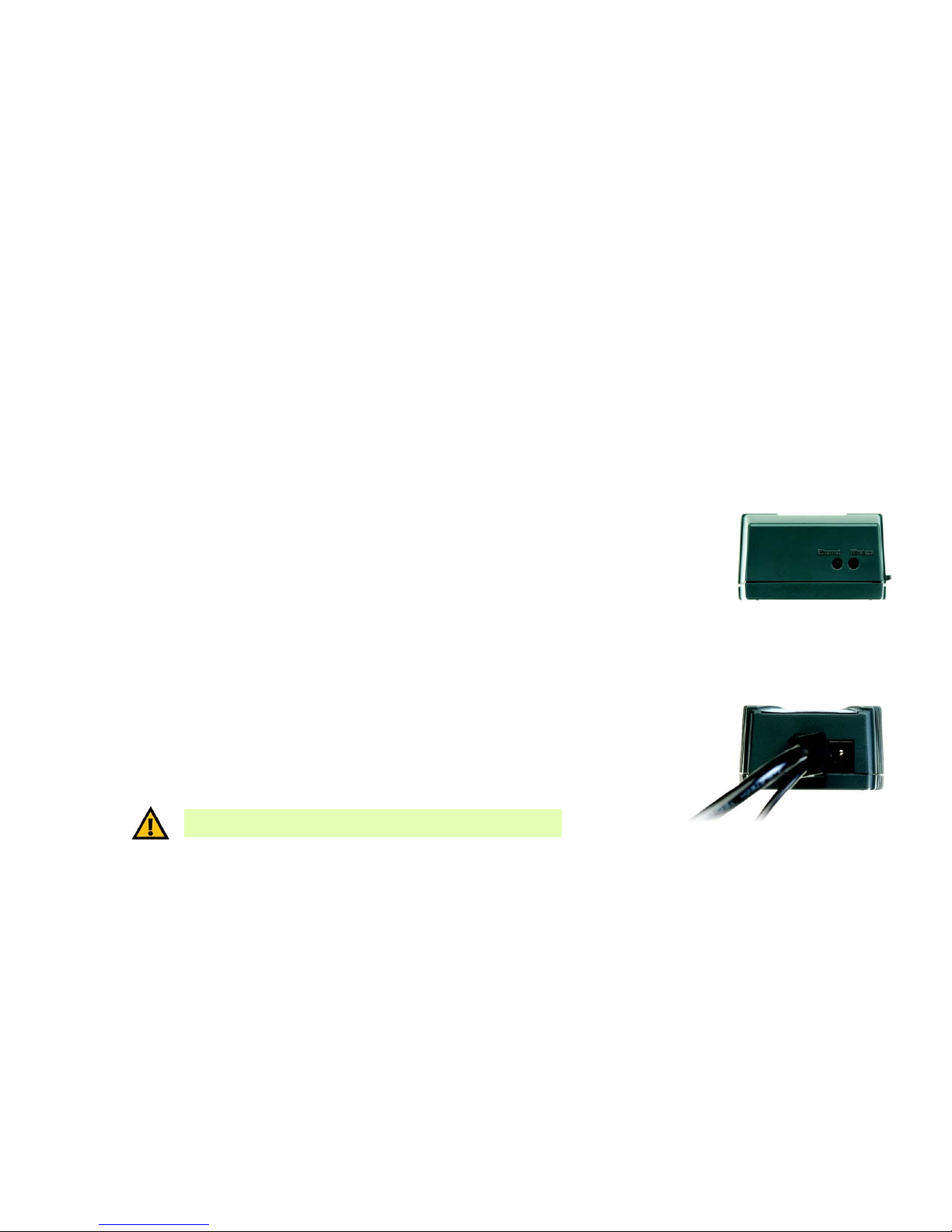
The Bridge has two LEDs, a Power port, and a permanently attached cable.
The LEDs
The Bridge has two LEDs to indicate network activity. (Not all versions of the Bridge have LEDS; however, all
Bridges work the same, with or without LEDs.)
Ethernet Green. The Ethernet LED lights up when the Bridge has an active connection to the wired network.
It flashes when the Bridge is experiencing wired network activity. The LED is not lit when the Bridge
has no active connection to the wired network.
Wireless Green. The Wireless LED lights up when the Bridge is connected to the wireless network. It flashes
when the Bridge is experiencing wireless network activity. The LED is not lit the Bridge is not
connected via wireless.
When the Bridge’s firmware is being upgraded, the Ethernet and Wireless LEDs alternate flashing.
The Port
The Bridge does not include its own power adapter; instead, it uses the power adapter of the Linksys phone
adapter or IP phone.
Power The Power port only supports a 5 V, 2 A, DC power adapter, which was included with your Linksys
phone adapter or IP phone. Do NOT connect any other type of power adapter to the Bridge.
Figure 3-1: LEDs
IMPORTANT: Using the wrong power adapter may cause malfunction or damage
your equipment.
Figure 3-2: Power Port
Page 11

6
Chapter 3: Getting to Know the Wireless-G Bridge for Phone Adapters
The Cable
Wireless-G Bridge for Phone Adapters
The Cable
The Bridge has a combination Ethernet network and power cable.
Network For setup, you will use the Ethernet network cable to connect the Bridge to your network router or
PC running the Setup Wizard. After setup, you will use this cable to connect the Bridge to the Linksys
phone adapter or IP phone.
Powe r After the Bridge has been configured, you will connect this cable to the Power port of the Linksys
phone adapter or IP phone. One power adapter will power the Bridge, as well as the phone adapter
or IP phone.
Figure 3-3: Combination Cable
Page 12
7
Chapter 4: Setting Up and Connecting the Wireless-G Bridge for Phone Adapters
Starting the Setup Wizard
Wireless-G Bridge for Phone Adapters
Chapter 4: Setting Up and Connecting the Wireless-G
Bridge for Phone Adapters
To configure the Bridge, run the Setup Wizard on the CD enclosed with the Bridge. This chapter and the Setup
Wizard will guide you through the installation procedure.
Starting the Setup Wizard
To begin the setup process, insert the Setup Wizard CD-ROM into your CD-ROM drive. The Setup Wizard should
run automatically, and the Welcome screen should appear. If it does not, click the Start button and choose Run.
In the field that appears, enter D:\setup.exe (if “D” is the letter of your CD-ROM drive).
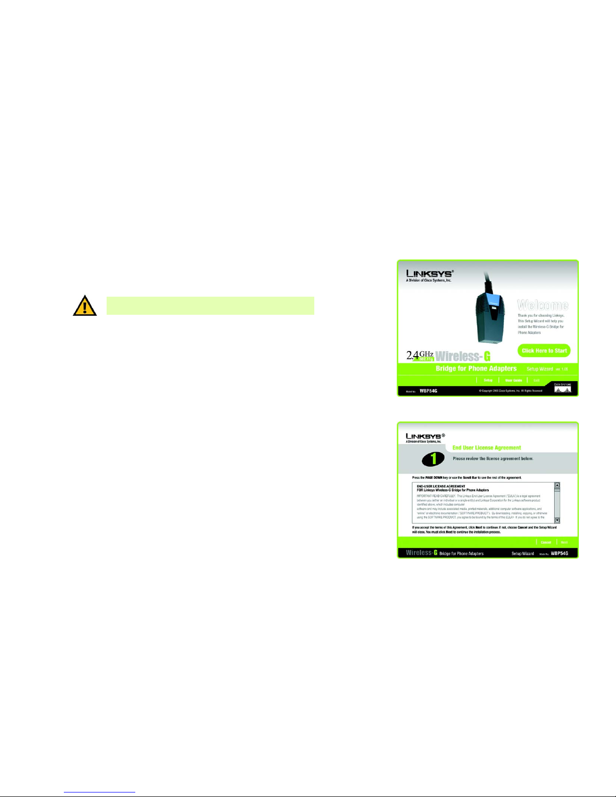
On the Welcome screen, you have the following choices:
Click Here to Start or Setup - Click the Click Here to Start or Setup button to begin the software installation
process.
User Guide - Click the User Guide button to open this User Guide.
Exit - Click Exit to exit the Setup Wizard.
Running the Setup Wizard
1. To install the Bridge, click the Click Here to Start button on the Welcome screen.
2. After reading the License Agreement, click Next if you agree and want to continue the installation, or click
Cancel to end the installation.
Figure 4-1: Welcome Screen
Figure 4-2: License Agreement Screen
IMPORTANT: Do not connect the Bridge until you are instructed to do
so or the setup will not work.
Page 13
8
Chapter 4: Setting Up and Connecting the Wireless-G Bridge for Phone Adapters
Running the Setup Wizard
Wireless-G Bridge for Phone Adapters
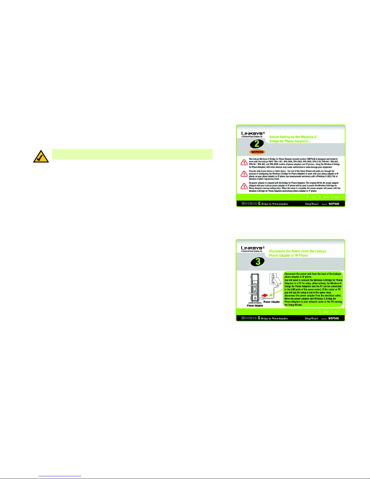
3. This screen will inform you about which Linksys phone adapters and IP phones work with the Bridge. Make
sure your phone adapter or IP phone is listed on-screen. Click Next to proceed with the installation process,
or click Back to return to the previous screen. To exit the Setup Wizard, click Exit.
4. You will use the PC running this Setup Wizard to set up the Bridge. Disconnect the power jack from the back
of the Linksys phone adapter or IP phone. (You will use this power adapter to power the Bridge.) If your
network router or this PC is in a different room, disconnect the power adapter from the electrical outlet. Move
the power adapter and Bridge to the room where your router or PC is located.
Click Next to proceed, or click Back to return to the previous screen.
Figure 4-3: Check for Compatibility Screen
Figure 4-4: Disconnect the Power from the Phone
Adapter or IP Phone Screen
NOTE: The power adapter for your Linksys phone adapter or IP phone will be used to
power the Bridge.
Page 14
9
Chapter 4: Setting Up and Connecting the Wireless-G Bridge for Phone Adapters
Running the Setup Wizard
Wireless-G Bridge for Phone Adapters
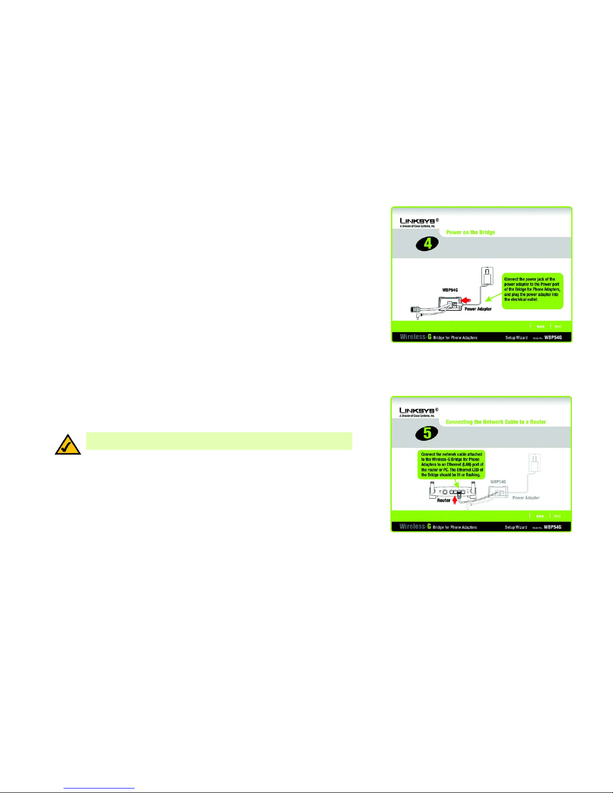
5. Connect the power jack to the Power port of the Bridge. Then plug the power adapter into an electrical outlet.
Click Next to proceed with the installation process, or click Back to return to the previous screen.
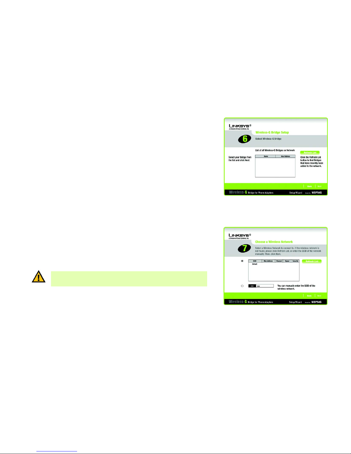
6. You will use the combination Ethernet network and power cable attached to the Bridge. Connect the Ethernet
network cable of the Bridge to an Ethernet network (LAN) port of the router or PC. (Do not use the power cable
now; you will use it later.)
Make sure the Bridge’s Ethernet LED is solidly lit or flashing.
Click Next to proceed, or click Back to return to the previous screen.
Figure 4-6: Connecting the Network Cable to a
Router Screen
Figure 4-5: Power on the Bridge Screen
NOTE: If you connect the Bridge to a router, make sure the Bridge and PC running the
Setup Wizard are connected to the Ethernet network (LAN) ports of the same router.
Page 15
10
Chapter 4: Setting Up and Connecting the Wireless-G Bridge for Phone Adapters
Running the Setup Wizard
Wireless-G Bridge for Phone Adapters
7. A list of all Bridges for Phone Adapters that can be detected by the Setup Wizard will be displayed. Select the
Bridge you are installing and click Next. If the Bridge you want is not displayed, click the Refresh List button
to search again.
8. This screen will display a list of wireless networks that can be detected and their status information: SSID
(network name), MAC Address, Channel, Signal (strength), and Security (method). Select the wireless network
you want.
If the network you want is not displayed, click the Refresh List button to search again.
To manually enter the SSID of the network you want, click the SSID radio button and complete the SSID field.
Click Next to proceed, or click Back to return to the previous screen.
Figure 4-7: Wireless-G Bridge Setup Screen
Figure 4-8: Choose a Wireless Network Screen
IMPORTANT: Some wireless access points or routers do not broadcast their status
information. If you do not see the network you want, click the SSID radio button and
manually enter its SSID.
Page 16

11
Chapter 4: Setting Up and Connecting the Wireless-G Bridge for Phone Adapters
Running the Setup Wizard
Wireless-G Bridge for Phone Adapters
9. Configure the wireless security settings. Select the method your network is using, WPA, WPA2, WEP (128-Bit),
or WEP (64-Bit). Then proceed to the appropriate instructions. If you are not using wireless security, select
Disabled, and proceed to step 10.
WPA
WPA automatically uses TKIP with dynamic encryption keys. Enter a passphrase on this screen.
Encryption - TKIP is automatically selected as the encryption method.
Passphrase - Enter a Passphrase, also called a pre-shared key, of 8-63 characters in the Passphrase field.
The longer and more complex your Passphrase is, the more secure your network will be.
Click Next to proceed, or click Back to return to the previous screen.
WPA2
WPA2 automatically uses AES with dynamic encryption keys (AES is a stronger encryption method than TKIP).
Enter a passphrase on this screen.
Encryption - AES is automatically selected as the encryption method.
Passphrase - Enter a Passphrase, also called a pre-shared key, of 8-63 characters in the Passphrase field.
The longer and more complex your Passphrase is, the more secure your network will be.
Click Next to proceed, or click Back to return to the previous screen.
Figure 4-9: Security Settings - WPA Screen
Figure 4-10: Security Settings - WPA2 Screen
wep (wired equivalent privacy): a method of encrypting network
data transmitted on a wireless network.
encryption: encoding data transmitted in a network.
wpa (wi-fi protected access): a wireless security protocol
using TKIP (Temporal Key Integrity Protocol) encryption.
wpa2 (wi-fi protected access 2): a wireless security protocol
using AES (Advanced Encryption Standard) encryption.
Page 17

12
Chapter 4: Setting Up and Connecting the Wireless-G Bridge for Phone Adapters
Running the Setup Wizard
Wireless-G Bridge for Phone Adapters
WEP (128-Bit) or WEP (64-Bit)
Enter a passphrase in the Passphrase field and click Next. If you want to manually enter a WEP key, leave the
Passphrase field blank and click Next.
Passphrase - Enter a passphrase in the Passphrase field, so a WEP key is automatically generated. The
passphrase is case-sensitive and should not be longer than 16 alphanumeric characters. It must match the
passphrase of your other wireless network devices and is compatible with Linksys wireless products only. (If
you have any non-Linksys wireless products, enter the WEP key manually on those products.)
A new screen will appear. If you entered a Passphrase, the WEP key(s) will be displayed. If you did not enter a
Passphrase, enter the WEP key(s) on this screen. Then select the key you will use from the Key Index drop-
down menu.
Key 1-4 - One to four fields will be displayed, depending on the level of encryption you have selected. The
WEP key you enter must match the WEP key of your wireless network. For 64-bit WEP encryption, enter
exactly 10 hexadecimal characters. For 128-bit WEP encryption, enter exactly 26 hexadecimal characters.
Valid hexadecimal characters are “0” to “9” and “A” to “F”.
Key Index - The default transmit key number is 1. If your network’s access point or wireless router uses
transmit key number 2, 3, or 4, select the appropriate number from the Key Index drop-down menu.
Click Next to proceed, or click Back to return to the previous screen.
Figure 4-12: Security Settings - WEP Keys Screen
Figure 4-11: Security Settings - WEP (64-Bit) Screen
Page 18

13
Chapter 4: Setting Up and Connecting the Wireless-G Bridge for Phone Adapters
Running the Setup Wizard
Wireless-G Bridge for Phone Adapters
10. The new settings will be displayed. Review them before you proceed. Click Next to save your new settings, or
click Back to return to the previous screen.
11. The Bridge will attempt to connect to the wireless network using the new settings.
Make sure the Bridge’s Wireless LED is solidly lit or flashing. This indicates that the Bridge has connected to
the wireless network. If the attempt succeeds, proceed to step 12.
If the attempt fails, you have two options offered by a pop-up screen. Click the Yes button to save the new
settings and proceed, or click the No button to return to the Choose a Wireless Network screen and
reconfigure the settings.
12. Disconnect the Ethernet network cable of the Bridge from the router or PC.
Click Next to proceed, or click Back to return to the previous screen.
Figure 4-13: Confirmation Screen
Figure 4-15: Disconnect the Network Cable from the
Router Screen
Figure 4-14: If the Bridge Does Not Connect... Screen
Page 19

14
Chapter 4: Setting Up and Connecting the Wireless-G Bridge for Phone Adapters
Running the Setup Wizard
Wireless-G Bridge for Phone Adapters
13. If the phone adapter or IP phone is in a different room, disconnect the power adapter from the electrical
outlet. Move the power adapter and Bridge to the location of the phone adapter or IP phone.
Click Next to proceed, or click Back to return to the previous screen.
14. Disconnect the Ethernet network cable from the phone adapter or IP phone.
You will use the combination Ethernet network and power cable attached to the Bridge. Connect the Ethernet
network cable of the Bridge to the phone adapter or IP phone.
Click Next to proceed, or click Back to return to the previous screen.
Figure 4-16: Disconnect the Power Adapter Screen
Figure 4-17: Disconnect the Network Cable from the
Phone Adapter Screen
Page 20

15
Chapter 4: Setting Up and Connecting the Wireless-G Bridge for Phone Adapters
Running the Setup Wizard
Wireless-G Bridge for Phone Adapters
15. Connect the power cable of the Bridge to the Power port of the phone adapter or IP phone. Then connect the
power adapter to an electrical outlet.
Make sure the Bridge’s Ethernet and Wireless LEDs are solidly lit or flashing.
Click Next to proceed, or click Back to return to the previous screen.
16. Make sure your cable connections match the cable connections shown on-screen.
Click Next to proceed, or click Back to return to the previous screen.
Figure 4-18: Connect the Attached Bridge Power Cable
to the Phone Adapter Screen
Figure 4-19: Wireless is Now Active Screen
Page 21

16
Chapter 4: Setting Up and Connecting the Wireless-G Bridge for Phone Adapters
Running the Setup Wizard
Wireless-G Bridge for Phone Adapters
17. The Congratulations screen will appear. Click Exit to exit the Setup Wizard, or click Online Registration to
register the Bridge at www.linksys.com/registration.
Congratulations! Setup is complete.
Figure 4-20: Congratulations Screen
Page 22

17
Appendix A: Troubleshooting
Common Problems and Solutions
Wireless-G Bridge for Phone Adapters
Appendix A: Troubleshooting
This appendix consists of two parts: “Common Problems and Solutions” and “Frequently Asked Questions.” This
appendix provides solutions to problems that may occur during the installation and operation of the Wireless-G
Bridge for Phone Adapters. Read the description below to solve your problems. If you can't find an answer here,
check the Linksys website at www.linksys.com/international.
Common Problems and Solutions
1. The Setup Wizard cannot detect the Wireless-G Bridge for Phone Adapters.
The Bridge cannot be configured over the wireless network. Confirm that the Bridge is properly connected to
your network router or PC running the Setup Wizard. Make sure the Ethernet network cable is securely
connected and the Ethernet LED should be solidly lit or flashing.
2. The speed of the wireless connection is very slow.
If there is significant traffic (“noise”) in your wireless environment, then the speed will drop. Make sure you
have a clear line of sight between your wireless devices. Also, some electrical and electronic devices
generate interference. You can often locate these by checking wireless data transmission speeds by powering
on and off a different device, one at a time.
3. The Linksys phone adapter or IP phone connected to the Bridge does not have a valid IP address.
This problem does not involve the Bridge (the Bridge only provides a connection between the wireless
network and the phone adapter or IP phone). Make sure the phone adapter or IP phone has been configured
properly, so that it is assigned a valid IP address. (The Bridge does not have its own IP address.)
4. The Setup Wizard reported that the Bridge has successfully connected to the wireless network;
however, the wireless connection does not seem to be working.
There may be an error with the Bridge’s security settings. Make sure you have written down the correct
settings for your wireless network. Then run the Setup Wizard for the Bridge. Check the following:
• If your wireless network has its security enabled, make sure the WEP key and other settings you entered
during the Bridge’s Setup Wizard are correct.
• If your wireless network has its security disabled, make sure no WEP key or other security setting was
entered during the Bridge’s Setup Wizard.
Page 23

18
Appendix A: Troubleshooting
Frequently Asked Questions
Wireless-G Bridge for Phone Adapters
Frequently Asked Questions
Which Linksys products will the Bridge work with?
The Bridge will work with these Linksys phone adapters and IP phones, listed by model number: PAP2, SPA1001,
SPA2000, SPA2002, SPA3000, SPA2100, SPA841, SPA842, SPA941, SPA942, and SPA9000. Do not use the Bridge
with any other products; otherwise, this may cause malfunction or even damage your equipment.
The Bridge does not include a power adapter. How do I supply power to it?
The Bridge uses the power adapter for your Linksys phone adapter or IP phone. A combination power and
Ethernet network cable is attached to the Bridge. You will use the power adapter and this cable to power the
Bridge and your Linksys phone adapter or IP phone. Refer to “Chapter 4: Setting Up and Configuring the
Wireless-G Bridge for Phone Adapters” for instructions.
What is the IEEE 802.11b standard?
It is one of the IEEE standards for wireless networks. The 802.11b standard allows wireless networking hardware
from different manufacturers to communicate, provided that the hardware complies with the 802.11b standard.
The 802.11b standard states a maximum data transfer rate of 11Mbps and an operating frequency of 2.4GHz.
What is the IEEE 802.11g standard?
It is one of the IEEE standards for wireless networks. The 802.11g standard allows wireless networking hardware
from different manufacturers to communicate, provided that the hardware complies with the 802.11g standard.
The 802.11g standard states a maximum data transfer rate of 54Mbps and an operating frequency of 2.4GHz.
What IEEE 802.11b features are supported?
The product supports the following IEEE 802.11b functions:
• CSMA/CA plus Acknowledge protocol
• Multi-Channel Roaming
• Automatic Rate Selection
• RTS/CTS feature
• Fragmentation
• Power Management
Page 24

19
Appendix A: Troubleshooting
Frequently Asked Questions
Wireless-G Bridge for Phone Adapters
What IEEE 802.11g features are supported?
The product supports the following IEEE 802.11g functions:
• CSMA/CA plus Acknowledge protocol
• OFDM protocol
• Multi-Channel Roaming
• Automatic Rate Selection
• RTS/CTS feature
• Fragmentation
• Power Management
What is infrastructure mode?
When a wireless network is set to infrastructure mode, the wireless network is configured to communicate with a
wired network through a wireless access point.
What is roaming?
Roaming is the ability of a portable computer to communicate continuously while the user is moving freely
throughout an area greater than that covered by a single access point. Before using the roaming function, the
workstation must make sure that it is the same channel number with the access point of dedicated coverage
area.
To achieve true seamless connectivity, the wireless LAN must incorporate a number of different functions. Each
node and access point, for example, must always acknowledge receipt of each message. Each node must
maintain contact with the wireless network even when not actually transmitting data. Achieving these functions
simultaneously requires a dynamic RF networking technology that links access points and nodes. In such a
system, the user’s end node undertakes a search for the best possible access to the system. First, it evaluates
such factors as signal strength and quality, as well as the message load currently being carried by each access
point and the distance of each access point to the wired backbone. Based on that information, the node next
selects the right access point and registers its address. Communications between end node and host computer
can then be transmitted up and down the backbone.
As the user moves on, the end node’s RF transmitter regularly checks the system to determine whether it is in
touch with the original access point or whether it should seek a new one. When a node no longer receives
acknowledgment from its original access point, it undertakes a new search. Upon finding a new access point, it
then re-registers, and the communication process continues.
What is the ISM band?
The FCC and their counterparts outside of the U.S. have set aside bandwidth for unlicensed use in the ISM
(Industrial, Scientific and Medical) band. Spectrum in the vicinity of 2.4 GHz, in particular, is being made available
Page 25

20
Appendix A: Troubleshooting
Frequently Asked Questions
Wireless-G Bridge for Phone Adapters
worldwide. This presents a truly revolutionary opportunity to place convenient high-speed wireless capabilities in
the hands of users around the globe.
What is Spread Spectrum?
Spread Spectrum technology is a wideband radio frequency technique developed by the military for use in
reliable, secure, mission-critical communications systems. It is designed to trade off bandwidth efficiency for
reliability, integrity, and security. In other words, more bandwidth is consumed than in the case of narrowband
transmission, but the trade-off produces a signal that is, in effect, louder and thus easier to detect, provided that
the receiver knows the parameters of the spread-spectrum signal being broadcast. If a receiver is not tuned to
the right frequency, a spread-spectrum signal looks like background noise. There are two main alternatives,
Direct Sequence Spread Spectrum (DSSS) and Frequency Hopping Spread Spectrum (FHSS).
What is DSSS? What is FHSS? And what are their differences?
Frequency-Hopping Spread-Spectrum (FHSS) uses a narrowband carrier that changes frequency in a pattern that
is known to both transmitter and receiver. Properly synchronized, the net effect is to maintain a single logical
channel. To an unintended receiver, FHSS appears to be short-duration impulse noise. Direct-Sequence SpreadSpectrum (DSSS) generates a redundant bit pattern for each bit to be transmitted. This bit pattern is called a chip
(or chipping code). The longer the chip, the greater the probability that the original data can be recovered. Even if
one or more bits in the chip are damaged during transmission, statistical techniques embedded in the radio can
recover the original data without the need for retransmission. To an unintended receiver, DSSS appears as low
power wideband noise and is rejected (ignored) by most narrowband receivers.
Would the information be intercepted while transmitting on air?
The Bridge features two-fold protection in security. On the hardware side, as with Direct Sequence Spread
Spectrum technology, it has the inherent security feature of scrambling. On the software side, the Bridge offers a
variety of security methods, including WEP and WPA, to enhance security and access control. For more
information, refer to “Appendix B: Wireless Security.”
What is WEP?
WEP is Wired Equivalent Privacy, a data privacy mechanism based on a shared key algorithm, as described in the
IEEE 802.11 standard. For more information, refer to “Appendix B: Wireless Security.”
What is WPA?
WPA is Wi-Fi Protected Access, a wireless security protocol that can be used in conjunction with a RADIUS
(Remote Authentication Dial-In User Service) server. For more information, refer to “Appendix B: Wireless
Security.”
Page 26

21
Appendix B: Wireless Security
Security Precautions
Wireless-G Bridge for Phone Adapters
Appendix B: Wireless Security
Linksys wants to make wireless networking as safe and easy for you as possible. The current generation of
Linksys products provide several network security features, but they require specific action on your part for
implementation. So, keep the following in mind whenever you are setting up or using your wireless network.
Security Precautions
The following is a complete list of security precautions to take (at least steps 1 through 5 should be followed):
1. Change the default SSID.
2. Disable SSID Broadcast.
3. Change the default password for the Administrator account.
4. Enable MAC Address Filtering.
5. Change the SSID periodically.
6. Use the highest encryption algorithm possible. Use WPA if it is available. Please note that this may reduce
your network performance.
7. Change the encryption keys periodically.
Security Threats Facing Wireless Networks
Wireless networks are easy to find. Hackers know that in order to join a wireless network, wireless networking
products first listen for “beacon messages”. These messages can be easily decrypted and contain much of the
network’s information, such as the network’s SSID (Service Set Identifier). Here are the steps you can take:
Change the administrator’s password regularly. With every wireless networking device you use, keep in mind
that network settings (SSID, WEP keys, etc.) are stored in its firmware. Your network administrator is the only
person who can change network settings. If a hacker gets a hold of the administrator’s password, he, too, can
change those settings. So, make it harder for a hacker to get that information. Change the administrator’s
password regularly.
NOTE: Some of these security features are
available only through the network router or
access point. Refer to the router or access
point’s documentation for more information.
Page 27

22
Appendix B: Wireless Security
Security Threats Facing Wireless Networks
Wireless-G Bridge for Phone Adapters
SSID. There are several things to keep in mind about the SSID:
1. Disable Broadcast
2. Make it unique
3. Change it often
Most wireless networking devices will give you the option of broadcasting the SSID. While this option may be
more convenient, it allows anyone to log into your wireless network. This includes hackers. So, don’t broadcast
the SSID.
Wireless networking products come with a default SSID set by the factory. (The Linksys default SSID is “linksys”.)
Hackers know these defaults and can check these against your network. Change your SSID to something unique
and not something related to your company or the networking products you use.
Change your SSID regularly so that any hackers who have gained access to your wireless network will have to
start from the beginning in trying to break in.
MAC Addresses. Enable MAC Address filtering. MAC Address filtering will allow you to provide access to only
those wireless nodes with certain MAC Addresses. This makes it harder for a hacker to access your network with
a random MAC Address.
WEP Encryption. Wired Equivalent Privacy (WEP) is often looked upon as a cure-all for wireless security
concerns. This is overstating WEP’s ability. Again, this can only provide enough security to make a hacker’s job
more difficult.
There are several ways that WEP can be maximized:
1. Use the highest level of encryption possible
2. Use “Shared Key” authentication
3. Change your WEP key regularly
WPA. Wi-Fi Protected Access (WPA) is the newest and best available standard in Wi-Fi security. Two modes are
available: WPA and WPA2. For encryption, WPA automatically uses Temporal Key Integrity Protocol (TKIP), which
incorporates Message Integrity Code (MIC) to provide protection against hackers. WPA2-Personal only uses
Advanced Encryption Standard (AES) encryption, which is stronger than TKIP and utilizes a symmetric 128-bit
block data encryption.
WPA. Enter a password in the Passphrase field of 8-63 characters.
IMPORTANT: Always remember that each
device in your wireless network MUST use
the same encryption method and encryption
key or your wireless network will not function
properly.
Page 28

23
Appendix B: Wireless Security
Security Threats Facing Wireless Networks
Wireless-G Bridge for Phone Adapters
WPA2. Enter a password in the Passphrase field of 8-63 characters.
Implementing encryption may have a negative impact on your network’s performance, but if you are transmitting
sensitive data over your network, encryption should be used.
These security recommendations should help keep your mind at ease while you are enjoying the most flexible
and convenient technology Linksys has to offer.
Page 29

24
Appendix C: Upgrading Firmware
Wireless-G Bridge for Phone Adapters
Appendix C: Upgrading Firmware
To upgrade the Bridge’s firmware, follow these instructions:
1. On a computer running Windows 2000 or XP, download the upgrade application (WBP54G Upgrade
Application.zip) and the latest firmware from Linksys's website at www.linksys.com/international.
2. Extract the files on your computer’s desktop. The unzipped firmware file is a .bin file, and the program to
install the upgrade application is an .exe file named Upgrade 210. Their icons will appear on your desktop.
3. Double-click the Upgrade 210 icon to install the Upgrade Utility on your computer.
If your computer is running Windows XP, you may see a security warning screen. Click the Run button to
proceed.
4. The Welcome screen will appear. Click the Next button.
Figure C-1:
Icons
Figure C-2: Security Warning for
Windows XP
Figure C-3: Upgrade Utility Setup -
Welcome
Page 30

25
Appendix C: Upgrading Firmware
Wireless-G Broadband Router
5. On the Choose Destination Location screen, click the Next button.
6. When the utility has been installed, a pop-up screen will appear. Click the OK button.
7. A new window will appear on your desktop. You will use it later in step 9.
Disconnect the Bridge’s combination Ethernet network and power cable from the phone adapter or IP phone.
If your PC is in a different room, disconnect the power adapter from the electrical outlet. Move the power
adapter and Bridge to the location of your PC.
8. Connect the Ethernet network cable of the Bridge to an Ethernet network (LAN) port of the PC.
If necessary, plug the power adapter into an electrical outlet.
9. In the new window on your desktop, double-click Upgrade Utility.
Figure C-4: Choose Destination
Location
Figure C-5: Setup
is Complete
Figure C-6: Start Upgrade Utility Program
Page 31

26
Appendix C: Upgrading Firmware
Wireless-G Broadband Router
10. The Upgrade Utility screen will appear. Click Browse, and then click Browse Targets.
11. The Browsed Devices on Network screen will appear. Click the Files button.
Figure C-8: Browsed Devices on
Network Screen - Click Files
Figure C-7: Upgrade Utility - Browse Targets
Page 32

27
Appendix C: Upgrading Firmware
Wireless-G Bridge for Phone Adapters
12. Select the extracted firmware file, and then click the Open button.
13. The BIN File Information screen will appear. Click the OK button.
14. On the Browsed Devices on Network screen, select the Bridge from the Devices List, and click the Upgrade
button.
Figure C-10: BIN File Information
Screen
Figure C-11: Browsed Devices on
Network Screen - Select Bridge
Figure C-9: Open Firmware File
Page 33

28
Appendix C: Upgrading Firmware
Wireless-G Bridge for Phone Adapters
15. The Upgrade Utility will upgrade the Bridge’s firmware. A pop-up screen will appear when the upgrade is
complete. Click the OK button.
16. Disconnect the Ethernet network cable from the PC.
If the phone adapter or IP phone is in a different room, disconnect the power adapter from the electrical
outlet. Move the power adapter and Bridge to the location of the phone adapter or IP phone.
17. Connect the Ethernet network cable of the Bridge to the phone adapter or IP phone.
18. Connect the power cable of the Bridge to the Power port of the phone adapter or IP phone.
If necessary, plug the power adapter into an electrical outlet.
Figure C-12: Upgrade
Successful
IMPORTANT: Do not disconnect the power adapter from the Bridge while the firmware is
being upgraded. Otherwise, damage may occur to the Bridge.
Page 34

29
Appendix D: Windows Help
Wireless-G Bridge for Phone Adapters
Appendix D: Windows Help
Almost all wireless products require Microsoft Windows. Windows is the most used operating system in the world
and comes with many features that help make networking easier. These features can be accessed through
Windows Help and are described in this appendix.
TCP/IP
Before a computer can communicate with an access point or wireless router, TCP/IP must be enabled. TCP/IP is a
set of instructions, or protocol, all PCs follow to communicate over a network. This is true for wireless networks
as well. Your PCs will not be able to utilize wireless networking without having TCP/IP enabled. Windows Help
provides complete instructions on enabling TCP/IP.
Shared Resources
If you wish to share printers, folder, or files over your network, Windows Help provides complete instructions on
utilizing shared resources.
Network Neighborhood/My Network Places
Other PCs on your network will appear under Network Neighborhood or My Network Places (depending upon the
version of Windows you're running). Windows Help provides complete instructions on adding PCs to your
network.
Page 35

30
Appendix E: Glossary
Wireless-G Bridge for Phone Adapters
Appendix E: Glossary
This glossary contains some basic networking terms you may come across when using this product. For more
advanced terms, see the complete Linksys glossary at http://www.linksys.com/glossary.
Access Point - A device that allows wireless-equipped computers and other devices to communicate with a
wired network. Also used to expand the range of a wireless network.
Ad-hoc - A group of wireless devices communicating directly with each other (peer-to-peer) without the use of
an access point.
AES (Advanced Encryption Standard) - A security method that uses symmetric 128-bit block data encryption.
Bandwidth - The transmission capacity of a given device or network.
Bit - A binary digit.
Boot - To start a device and cause it to start executing instructions.
Broadband - An always-on, fast Internet connection.
Browser - An application program that provides a way to look at and interact with all the information on the
World Wide Web.
Byte - A unit of data that is usually eight bits long
Cable Modem - A device that connects a computer to the cable television network, which in turn connects to the
Internet.
Daisy Chain - A method used to connect devices in a series, one after the other.
DDNS (Dynamic Domain Name System) - Allows the hosting of a website, FTP server, or e-mail server with a
fixed domain name (e.g., www.xyz.com) and a dynamic IP address.
Default Gateway - A device that forwards Internet traffic from your local area network.
DHCP (Dynamic Host Configuration Protocol) - A networking protocol that allows administrators to assign
temporary IP addresses to network computers by “leasing” an IP address to a user for a limited amount of time,
instead of assigning permanent IP addresses.
Page 36

31
Appendix E: Glossary
Wireless-G Bridge for Phone Adapters
DMZ (Demilitarized Zone) - Removes the Router's firewall protection from one PC, allowing it to be “seen” from
the Internet.
DNS (Domain Name Server) - The IP address of your ISP's server, which translates the names of websites into IP
addresses.
Domain - A specific name for a network of computers.
Download - To receive a file transmitted over a network.
DSL (Digital Subscriber Line) - An always-on broadband connection over traditional phone lines.
Dynamic IP Address - A temporary IP address assigned by a DHCP server.
EAP (Extensible Authentication Protocol) - A general authentication protocol used to control network access.
Many specific authentication methods work within this framework.
Encryption - Encoding data transmitted in a network.
Ethernet - IEEE standard network protocol that specifies how data is placed on and retrieved from a common
transmission medium.
Firewall - A set of related programs located at a network gateway server that protects the resources of a
network from users from other networks.
Firmware - The programming code that runs a networking device.
FTP (File Transfer Protocol) - A protocol used to transfer files over a TCP/IP network.
Full Duplex - The ability of a networking device to receive and transmit data simultaneously.
Gateway - A device that interconnects networks with different, incompatible communications protocols.
Half Duplex - Data transmission that can occur in two directions over a single line, but only one direction at a
time.
HTTP (HyperText Transport Protocol) - The communications protocol used to connect to servers on the World
Wide Web.
Infrastructure - A wireless network that is bridged to a wired network via an access point.
IP (Internet Protocol) - A protocol used to send data over a network.
Page 37

32
Appendix E: Glossary
Wireless-G Bridge for Phone Adapters
IP Address - The address used to identify a computer or device on a network.
IPCONFIG - A Windows 2000 and XP utility that displays the IP address for a particular networking device.
IPSec (Internet Protocol Security) - A VPN protocol used to implement secure exchange of packets at the IP layer.
ISP (Internet Service Provider) - A company that provides access to the Internet.
LAN - The computers and networking products that make up your local network.
MAC (Media Access Control) Address - The unique address that a manufacturer assigns to each networking
device.
Mbps (MegaBits Per Second) - One million bits per second; a unit of measurement for data transmission.
NAT (Network Address Translation) - NAT technology translates IP addresses of a local area network to a different
IP address for the Internet.
Network - A series of computers or devices connected for the purpose of data sharing, storage, and/or
transmission between users.
Packet - A unit of data sent over a network.
Passphrase - Used much like a password, a passphrase simplifies the WEP encryption process by automatically
generating the WEP encryption keys for Linksys products.
Ping (Packet INternet Groper) - An Internet utility used to determine whether a particular IP address is online.
POP3 (Post Office Protocol 3) - A standard mail server commonly used on the Internet.
Port - The connection point on a computer or networking device used for plugging in cables or adapters.
Power over Ethernet (PoE) - A technology enabling an Ethernet network cable to deliver both data and power.
PPPoE (Point to Point Protocol over E
thernet) - A type of broadband connection that provides authentication
(username and password) in addition to data transport.
PPTP (Point-to-Point Tunneling Protocol) - A VPN protocol that allows the Point to Point Protocol (PPP) to be
tunneled through an IP network. This protocol is also used as a type of broadband connection in Europe.
RADIUS (Remote Authentication Dial-In User Service) - A protocol that uses an authentication server to control
network access.
Page 38

33
Appendix E: Glossary
Wireless-G Bridge for Phone Adapters
RJ-45 (Registered Jack-45) - An Ethernet connector that holds up to eight wires.
Roaming - The ability to take a wireless device from one access point's range to another without losing the
connection.
Router - A networking device that connects multiple networks together.
Server - Any computer whose function in a network is to provide user access to files, printing, communications,
and other services.
SMTP (Simple Mail Transfer Protocol) - The standard e-mail protocol on the Internet.
SNMP (Simple Network Management Protocol) - A widely used network monitoring and control protocol.
SPI (Stateful Packet Inspection) Firewall - A technology that inspects incoming packets of information before
allowing them to enter the network.
SSID (Service Set IDentifier) - Your wireless network's name.
Static IP Address - A fixed address assigned to a computer or device that is connected to a network.
Static Routing - Forwarding data in a network via a fixed path.
Subnet Mask - An address code that determines the size of the network.
Switch - 1. A data switch that connects computing devices to host computers, allowing a large number of
devices to share a limited number of ports. 2. A device for making, breaking, or changing the connections in an
electrical circuit.
TCP (Transmission Control Protocol) - A network protocol for transmitting data that requires acknowledgement
from the recipient of data sent.
TCP/IP (Transmission Control Protocol/Internet Protocol) - A set of instructions PCs use to communicate over a
network.
Tel ne t - A user command and TCP/IP protocol used for accessing remote PCs.
TFTP (Trivial File Transfer Protocol) - A version of the TCP/IP FTP protocol that has no directory or password
capability.
Throughput - The amount of data moved successfully from one node to another in a given time period.
Page 39

34
Appendix E: Glossary
Wireless-G Bridge for Phone Adapters
TKIP (Temporal Key Integrity Protocol) - a wireless encryption protocol that provides dynamic encryption keys for
each packet transmitted.
Topology - The physical layout of a network.
TX Rate - Transmission Rate.
Upgrade - To replace existing software or firmware with a newer version.
Upload - To transmit a file over a network.
URL (Uniform Resource Locator) - The address of a file located on the Internet.
VPN (Virtual Private Network) - A security measure to protect data as it leaves one network and goes to another
over the Internet.
WAN (Wide Area Network)- The Internet.
WEP (Wired Equivalent Privacy) - A method of encrypting network data transmitted on a wireless network for
greater security.
WLAN (Wireless Local Area Network) - A group of computers and associated devices that communicate with
each other wirelessly.
WPA (Wi-Fi Protected Access) - A wireless security protocol using TKIP (Temporal Key Integrity Protocol)
encryption, which can be used in conjunction with a RADIUS server.
Page 40

35
Appendix F: Specifications
Wireless-G Bridge for Phone Adapters
Appendix F: Specifications
Model WBP54G
Standards IEEE 802.3, IEEE 802.3u, IEEE 802.11b, IEEE 802.11g
Port One 5V/2A DC power input port
LEDs Ethernet and Wireless
Cabling Type One combo-power/Ethernet cable (with built-in
connectors) attached to the device
# of Antennas One internal Helix antenna
Connector Type One female barrel jack (power input), one male barrel
jack (power output), one RJ-45 Ethernet connector
RF Pwr (EIRP) in dBm 13 ±1,5dBm (802.11g) / 17 ±1,5dBm (802.11b)
Antenna Gain in dBi 1 dBi
Security Features WPA2, WPA, WEP
WEP Key Bits 64, 128
Dimensions 51 mm x 92 mm x 29 mm
(2,01" x 3,62" x 1,14")
Unit Weight 0,072 kg (2,54 oz.)
Power External, 5V DC, 2,0A (Not included, use the power
adapter shipped with Linksys phone adapter or IP
phone products)
Page 41

36
Appendix F: Specifications
Wireless-G Bridge for Phone Adapters
Certifications FCC, CE, cUL, IC-03, Wi-Fi, WPA, WPA2
Operating Temp. 0° C to 40° C (32° F to 104° F)
Storage Temp. -20° C to 70° C (-4° F to 158° F)
Operating Humidity 10% to 85% Non-Condensing
Storage Humidity 5% to 90% Non-Condensing
Page 42

37
Appendix G: Warranty Information
Wireless-G Bridge for Phone Adapters
Appendix G: Warranty Information
Linksys warrants to You that, for a period of three years (the “Warranty Period”), your Linksys Product will be substantially
free of defects in materials and workmanship under normal use. Your exclusive remedy and Linksys' entire liability under
this warranty will be for Linksys at its option to repair or replace the Product or refund Your purchase price less any rebates.
This limited warranty extends only to the original purchaser.
If the Product proves defective during the Warranty Period call Linksys Technical Support in order to obtain a Return
Authorization Number, if applicable. BE SURE TO HAVE YOUR PROOF OF PURCHASE ON HAND WHEN CALLING. If You are
requested to return the Product, mark the Return Authorization Number clearly on the outside of the package and include a
copy of your original proof of purchase. RETURN REQUESTS CANNOT BE PROCESSED WITHOUT PROOF OF PURCHASE. You
are responsible for shipping defective Products to Linksys. Linksys pays for UPS Ground shipping from Linksys back to You
only. Customers located outside of the United States of America and Canada are responsible for all shipping and handling
charges.
ALL IMPLIED WARRANTIES AND CONDITIONS OF MERCHANTABILITY OR FITNESS FOR A PARTICULAR PURPOSE ARE LIMITED
TO THE DURATION OF THE WARRANTY PERIOD. ALL OTHER EXPRESS OR IMPLIED CONDITIONS, REPRESENTATIONS AND
WARRANTIES, INCLUDING ANY IMPLIED WARRANTY OF NON-INFRINGEMENT, ARE DISCLAIMED. Some jurisdictions do not
allow limitations on how long an implied warranty lasts, so the above limitation may not apply to You. This warranty gives
You specific legal rights, and You may also have other rights which vary by jurisdiction.
This warranty does not apply if the Product (a) has been altered, except by Linksys, (b) has not been installed, operated,
repaired, or maintained in accordance with instructions supplied by Linksys, or (c) has been subjected to abnormal physical
or electrical stress, misuse, negligence, or accident. In addition, due to the continual development of new techniques for
intruding upon and attacking networks, Linksys does not warrant that the Product will be free of vulnerability to intrusion or
attack.
TO THE EXTENT NOT PROHIBITED BY LAW, IN NO EVENT WILL LINKSYS BE LIABLE FOR ANY LOST DATA, REVENUE OR PROFIT,
OR FOR SPECIAL, INDIRECT, CONSEQUENTIAL, INCIDENTAL OR PUNITIVE DAMAGES, REGARDLESS OF THE THEORY OF
LIABILITY (INCLUDING NEGLIGENCE), ARISING OUT OF OR RELATED TO THE USE OF OR INABILITY TO USE THE PRODUCT
(INCLUDING ANY SOFTWARE), EVEN IF LINKSYS HAS BEEN ADVISED OF THE POSSIBILITY OF SUCH DAMAGES. IN NO EVENT
WILL LINKSYS’ LIABILITY EXCEED THE AMOUNT PAID BY YOU FOR THE PRODUCT. The foregoing limitations will apply even if
any warranty or remedy provided under this Agreement fails of its essential purpose. Some jurisdictions do not allow the
exclusion or limitation of incidental or consequential damages, so the above limitation or exclusion may not apply to You.
This Warranty is valid and may be processed only in the country of purchase.
Please direct all inquiries to: Linksys, P.O. Box 18558, Irvine, CA 92623 USA.
Page 43

38
Appendix H: Regulatory Information
Wireless-G Bridge for Phone Adapters
Appendix H: Regulatory Information
Federal Communication Commission Interference Statement
This equipment has been tested and found to comply with the limits for a Class B digital device, pursuant to
Part 15 of the FCC Rules. These limits are designed to provide reasonable protection against harmful interference in a
residential installation. This equipment generates, uses and can radiate radio frequency energy and, if not installed and
used in accordance with the instructions, may cause harmful interference to radio communications. However, there is no
guarantee that interference will not occur in a particular installation. If this equipment does cause harmful interference to
radio or television reception, which can be determined by turning the equipment off and on, the user is encouraged to try
to correct the interference by one of the following measures:
• Reorient or relocate the receiving antenna.
• Increase the separation between the equipment and receiver.
• Connect the equipment into an outlet on a circuit different from that to which the receiver is connected.
• Consult the dealer or an experienced radio/TV technician for help.
This device complies with Part 15 of the FCC Rules. Operation is subject to the following two conditions: (1) This device
may not cause harmful interference, and (2) this device must accept any interference received, including interference that
may cause undesired operation.
FCC Caution: Any changes or modifications not expressly approved by the party responsible for compliance could void the
user's authority to operate this equipment.
IMPORTANT NOTE: FCC Radiation Exposure Statement
This equipment complies with FCC radiation exposure limits set forth for an uncontrolled environment. This equipment
should be installed and operated with minimum distance 20cm between the radiator & your body. To maintain compliance
with FCC RF exposure compliance requirements, please avoid direct contact to the transmitting antenna during
transmitting.
This transmitter must not be co-located or operating in conjunction with any other antenna or transmitter.
We declare that the product is limited in CH1~CH11 by specified firmware controlled in the USA.
Page 44

39
Appendix H: Regulatory Information
Wireless-G Bridge for Phone Adapters
Safety Notices
Caution: To reduce the risk of fire, use only No.26 AWG or larger telecommunication line cord.
Do not use this product near water, for example, in a wet basement or near a swimming pool.
Avoid using this product during an electrical storm. There may be a remote risk of electric shock from lightning.
Industry Canada
The use of this device in a system operating either partially or completely outdoors may require the user to obtain a license
for the system according to the Canadian regulations.
This device complies with Industry Canada ICES-003 and RSS210 rules.
IC Statement
Operation is subject to the following two conditions:
1. This device may not cause interference and
2. This device must accept any interference, including interference that may cause undesired operation of the device.
Industrie Canada
L'utilisation de ce périphérique dans un système utilisé partiellement ou totalement en extérieur peut conduire l'utilisateur
à l'obtention d'une licence pour ce système conformément aux règles en vigueur au Canada.
Cet appareil est conforme aux normes NMB-003 et RSS210 d'Industrie Canada.
Déclaration d'Industrie Canada
Le fonctionnement est soumis aux conditions suivantes :
1. Ce périphérique ne doit pas causer d'interférences;
2. Ce périphérique doit accepter toutes les interférences reçues, y compris celles qui risquent d'entraîner un
fonctionnement indésirable.
Page 45

40
Appendix H: Regulatory Information
Wireless-G Bridge for Phone Adapters
Compliance Information for 2.4-GHz Wireless Products
Relevant to the EU and Other Countries Following the EU
Directive 1999/5/EC (R&TTE Directive)
Declaration of Conformity with Regard to the EU Directive
1999/5/EC (R&TTE Directive)
Page 46

41
Appendix H: Regulatory Information
Wireless-G Bridge for Phone Adapters
The following standards were applied during the assessment of the product against the requirements of the Directive
1999/5/EC:
• Radio: EN 300 328
• EMC: EN 301 489-1, EN 301 489-17
• Safety: EN 60950 and either EN 50385 or EN 50371
CE Marking
For the Linksys Wireless-B and Wireless-G products, the following CE mark, notified body number (where applicable), and
class 2 identifier are added to the equipment.
Check the CE label on the product to find out which notified body was involved during the assessment.
National Restrictions
This product may be used in all EU countries (and other countries following the EU directive 1999/5/EC) without any
limitation except for the countries mentioned below:
Ce produit peut être utilisé dans tous les pays de l’UE (et dans tous les pays ayant transposés la directive 1999/5/CE) sans
aucune limitation, excepté pour les pays mentionnés ci-dessous:
Questo prodotto è utilizzabile in tutte i paesi EU (ed in tutti gli altri paesi che seguono le direttive EU 1999/5/EC) senza
nessuna limitazione, eccetto per i paesii menzionati di seguito:
Das Produkt kann in allen EU Staaten ohne Einschränkungen eingesetzt werden (sowie in anderen Staaten die der EU
Direktive 1999/5/CE folgen) mit Außnahme der folgenden aufgeführten Staaten:
NOTE: For all products, the Declaration of Conformity is available through one or more of these options:
• A pdf file is included on the product's CD.
• A print copy is included with the product.
• A pdf file is available on the product's webpage. Visit www.linksys.com/international and select your country or
region. Then select your product.
If you need any other technical documentation, see the “Technical Documents on www.linksys.com/international”
section, as shown later in this appendix.
or or
Page 47

42
Appendix H: Regulatory Information
Wireless-G Bridge for Phone Adapters
Belgium
The Belgian Institute for Postal Services and Telecommunications (BIPT) must be notified of any outdoor wireless link
having a range exceeding 300 meters. Please check http://www.bipt.be for more details.
Draadloze verbindingen voor buitengebruik en met een reikwijdte van meer dan 300 meter dienen aangemeld te worden
bij het Belgisch Instituut voor postdiensten en telecommunicatie (BIPT). Zie http://www.bipt.be voor meer gegevens.
Les liaisons sans fil pour une utilisation en extérieur d’une distance supérieure à 300 mètres doivent être notifiées à
l’Institut Belge des services Postaux et des Télécommunications (IBPT). Visitez http://www.ibpt.be pour de plus
amples détails.
France
In case the product is used outdoors, the output power is restricted in some parts of the band. See Table 1 or check
http://www.arcep.fr/ for more details.
Dans la cas d’une utilisation en extérieur, la puissance de sortie est limitée pour certaines parties de la bande. Reportezvous à la table 1 ou visitez http://www.arcep.fr/ pour de plus amples détails.
Italy
This product meets the National Radio Interface and the requirements specified in the National Frequency Allocation Table
for Italy. Unless operating within the boundaries of the owner’s property, the use of this 2.4 GHz Wireless LAN product
requires a ‘general authorization’. Please check with http://www.comunicazioni.it/it/ for more details.
Questo prodotto è conforme alla specifiche di Interfaccia Radio Nazionali e rispetta il Piano Nazionale di ripartizione delle
frequenze in Italia. Se non viene installato all’interno del proprio fondo, l’utilizzo di prodotti Wireless LAN a 2.4 GHz richiede
una “Autorizzazione Generale”. Consultare http://www.comunicazioni.it/it/ per maggiori dettagli.
Table 1: Applicable Power Levels in France
Location Frequency Range (MHz) Power (EIRP)
Indoor (No restrictions) 2400-2483.5 100 mW (20 dBm)
Outdoor 2400-2454
2454-2483.5
100 mW (20 dBm)
10 mW (10 dBm)
Page 48

43
Appendix H: Regulatory Information
Wireless-G Bridge for Phone Adapters
Product Usage Restrictions
This product is designed for indoor usage only. Outdoor usage is not recommended.
This product is designed for use with the standard, integral or dedicated (external) antenna(s) that is/are shipped together
with the equipment. However, some applications may require the antenna(s), if removable, to be separated from the
product and installed remotely from the device by using extension cables. For these applications, Linksys offers an R-SMA
extension cable (AC9SMA) and an R-TNC extension cable (AC9TNC). Both of these cables are 9 meters long and have a
cable loss (attenuation) of 5 dB. To compensate for the attenuation, Linksys also offers higher gain antennas, the HGA7S
(with R-SMA connector) and HGA7T (with R-TNC connector). These antennas have a gain of 7 dBi and may only be used
with either the R-SMA or R-TNC extension cable.
Combinations of extension cables and antennas resulting in a radiated power level exceeding 100 mW EIRP are illegal.
Power Output of Your Device
To comply with your country’s regulations, you may have to change the power output of your wireless device. Proceed to
the appropriate section for your device.
Wireless Adapters
Wireless adapters have the power output set to 100% by default. Maximum power output on each adapter does not exceed
20 dBm (100 mW); it is generally 18 dBm (64 mW) or below. If you need to alter your wireless adapter’s power output,
follow the appropriate instructions for your computer’s Windows operating system:
Windows XP
3. Double-click the Wireless icon in your desktop’s system tray.
4. Open the Wireless Network Connection window.
5. Click the Properties button.
6. Select the General tab, and click the Configure button.
7. In the Properties window, click the Advanced tab.
8. Select Power Output.
9. From the pull-down menu on the right, select the wireless adapter’s power output percentage.
NOTE: The power output setting may not be available on all wireless products. For more information, refer to
the documentation on your product’s CD or http://www.linksys.com/international.
Page 49

44
Appendix H: Regulatory Information
Wireless-G Bridge for Phone Adapters
Windows 2000
1. Open the Control Panel.
2. Double-click Network and Dial-Up Connections.
3. Select your current wireless connection, and select Properties.
4. From the Properties screen, click the Configure button.
5. Click the Advanced tab, and select Power Output.
6. From the pull-down menu on the right, select the wireless adapter’s power setting.
If your computer is running Windows Millennium or 98, then refer to Windows Help for instructions on how to access the
advanced settings of a network adapter.
Wireless Access Points, Routers, or Other Wireless Products
If you have a wireless access point, router or other wireless product, use its Web-based Utility to configure its power
output setting (refer to the product’s documentation for more information).
Technical Documents on www.linksys.com/international
Follow these steps to access technical documents:
1. Enter http://www.linksys.com/international in your web browser.
2. Select the country or region in which you live.
3. Click the Products tab.
4. Select the appropriate product category.
5. Select the product sub-category, if necessary.
6. Select the product.
7. Select the type of documentation you want from the More Information section. The document will open in PDF format if
you have Adobe Acrobat installed on your computer.
NOTE: If you have questions regarding the compliance of these products or you cannot find the information
you need, please contact your local sales office or visit http://www.linksys.com/international for more details.
Page 50

45
Appendix H: Regulatory Information
Wireless-G Bridge for Phone Adapters
User Information for Consumer Products Covered by EU Directive 2002/96/EC on Waste Electric and Electronic
Equipment (WEEE)
This document contains important information for users with regards to the proper disposal and recycling of Linksys
products. Consumers are required to comply with this notice for all electronic products bearing the following symbol:
Page 51

46
Appendix H: Regulatory Information
Wireless-G Bridge for Phone Adapters
Page 52

47
Appendix H: Regulatory Information
Wireless-G Bridge for Phone Adapters
Page 53

48
Appendix H: Regulatory Information
Wireless-G Bridge for Phone Adapters
Page 54

49
Appendix H: Regulatory Information
Wireless-G Bridge for Phone Adapters
For more information, visit www.linksys.com/international.
Page 55

50
Appendix I: Contact Information
Wireless-G Bridge for Phone Adapters
Appendix I: Contact Information
Need to contact Linksys?
Visit us online for information on the latest products and updates to your existing products at:
http://www.linksys.com/international
If you experience problems with any Linksys product, you can e-mail us at:
In Europe E-mail Address
Austria support.at@linksys.com
Belgium support.be@linksys.com
Denmark support.dk@linksys.com
France support.fr@linksys.com
Germany support.de@linksys.com
Italy support.it@linksys.com
Netherlands support.nl@linksys.com
Norway support.no@linksys.com
Portugal support.pt@linksys.com
Spain support.es@linksys.com
Sweden support.se@linksys.com
Switzerland support.ch@linksys.com
United Kingdom & Ireland support.uk@linksys.com
Outside of Europe E-mail Address
Asia Pacific asiasupport@linksys.com (English only)
Latin America support.portuguese@linksys.com or support.spanish@linksys.com
Middle East & Africa support.mea@linksys.com (English only)
U.S. and Canada support@linksys.com
 Loading...