

Page 1
¸
SFE1000P 8-port 10/100 Ethernet Switch with
PoE Reference Guide
March 2008
SFE1000P 8-port 10/100 Ethernet Switch with PoE
Reference Guide
SFE1000P 8-PORT 10/100 ETHERNET SWITCH WITH POE REFERENCE GUIDE
Page 2

© Copyright 2008, Cisco Systems, Inc.
Specifications are subject to change without notice.
Linksys, the Cisco Systems logo, the Linksys Logo, and the Linksys One logo are registered trademarks of Cisco
Systems, Inc. All other trademarks mentioned in this document are the property of their respective owners.
Document Revision History
Revision Date Description
1.0 March 2008 Initial release
Page 3

Contents
SFE1000P Gigabit Ethernet Switch Reference Guide
Chapter 1: Preface . . . . . . . . . . . . . . . . . . . . 1
Audience 1
Purpose 1
Organization 1
Chapter 2: Getting Started . . . . . . . . . . . . . . . . . 3
Starting the Application 3
Understanding the Interface 4
Device Representation 6
Using the Linksys Management Buttons 6
Using Screen and Table Options 7
Adding Device Information 7
Modifying Device Information 7
Deleting Device Information 7
Resetting the Device 8
Logging Off The Device 8
Chapter 3: Managing Device Information . . . . . . . . . . . 9
Understanding the Device Zoom View 9
Defining General System Information 10
Resetting the Device 11
Chapter 4: Managing Power-over-Ethernet Devices . . . . . . . . 12
PoE Settings 13
Edit PoE 14
Chapter 5: Configuring Device Security . . . . . . . . . . . . 16
Passwords Management 16
Add Local User 17
Modifying the Local User Settings 17
Defining Authentication 18
Defining Authentication Profiles 18
Add Authentication Profile 19
Modify the Authentication Profile 20
Mapping Authentication Profiles 21
Defining TACACS+ 22
Add TACACS+ Server 24
Modifying TACACS+ Settings 25
Defining RADIUS 26
Add RADIUS Server 27
Modifying RADIUS Server Settings 29
Defining Access Method 30
Defining Access Profiles 30
Add Access Profile Page 31
Defining Profile Rules 33
1
Page 4

Contents
SFE1000P Gigabit Ethernet Switch Reference Guide
Add Profile Rule 35
Modifying Profile Rules 36
Defining Traffic Control 38
Defining Storm Control 38
Modifying Storm Control 39
Defining Port Security 40
Modifying Port Security 42
Defining 802.1x 44
Defining 802.1X Properties 44
Defining Port Authentication 46
Modifying 8021X Security 48
Defining Multiple Hosts 50
Modifying Multiple Host Settings 51
Defining Authenticated Host 52
Defining Access Control 53
Defining MAC Based ACL 53
Adding an ACL 55
Adding Rule to MAC Based ACL 56
Defining IP Based ACL 58
Add IP Based ACL 61
Adding an IP Based Rule 63
Defining ACL Binding 65
Modifying ACL Binding 66
Defining DoS Prevention 67
Global Settings 67
Defining Martian Addresses 68
Add Martian Address Page 69
Chapter 6: Configuring Device Interfaces . . . . . . . . . . . . 70
Defining Port Settings 70
Modifying Port Settings 72
Defining LAG Management 75
Modifying LAG Membership 77
Defining LAG Settings 78
LAG Configuration Settings 79
Configuring LACP 81
Modify LACP Parameter Settings 82
Chapter 7: Configuring VLANs . . . . . . . . . . . . . . . 83
Defining VLAN Properties 84
Add VLAN 85
Modifying VLANs 85
Defining VLAN Membership 86
Modifying VLAN Membership 87
Defining Interface Settings 88
Modifying VLAN Interface Settings 89
2
Page 5

Contents
SFE1000P Gigabit Ethernet Switch Reference Guide
Configuring GVRP Settings 90
Modifying GVRP Settings 91
Defining VLAN Protocol Group 92
Add Protocol Group 93
Modifying Protocol Groups 93
Defining VLAN Protocol Port 94
Add Protocol Port to VLAN 94
Chapter 8: Configuring IP Information . . . . . . . . . . . . 96
Domain Name System 96
Defining DNS Server 96
Add DNS Server 98
Mapping DNS Hosts 98
Add DNS Host 99
Configuring Layer 2 IP Addresses 100
Defining IP Interfaces 100
Enabling ARP 101
Add ARP 102
Modifying ARP Settings 103
Chapter 9: Defining Address Tables . . . . . . . . . . . . 104
Defining Static Addresses 104
Add Static MAC Address 105
Defining Dynamic Addresses 106
Chapter 10: Configuring Multicast Forwarding . . . . . . . . 108
IGMP Snooping 108
Modifying IGMP Snooping 109
Defining Multicast Bridging Groups 110
Add Multicast Group 111
Modifying a Multicast Group 112
Defining Multicast Forwarding 113
Modifying Multicast Forwarding 114
Chapter 11: Configuring Spanning Tree . . . . . . . . . . . 115
Defining STP Properties 116
Global Settings 116
Defining Interface Settings 118
Modifying Interface Settings 120
Defining Rapid Spanning Tree 122
Modifying RTSP 124
Defining Multiple Spanning Tree 126
Defining MSTP Properties 126
Mapping MSTP Instances to VLAN 127
Defining MSTP Instance Settings 128
Defining MSTP Interface Settings 129
3
Page 6

Contents
SFE1000P Gigabit Ethernet Switch Reference Guide
Interface Table 131
Chapter 12: Configuring SNMP . . . . . . . . . . . . . . 134
Configuring SNMP Security 135
Defining the SNMP Engine ID 135
Defining SNMP Views 136
Add SNMP View 137
Defining SNMP Users 138
Add SNMP Group Membership 139
Modifying SNMP Users 140
Define SNMP Groups 141
Adding SNMP Group Profiles 142
Modifying SNMP Group Profile Settings 143
Defining SNMP Communities 144
Adding SNMP Communities 145
Modifying SNMP Community Settings 146
Defining Trap Management 147
Defining Trap Settings 147
Configuring Station Management 148
Adding a SNMP Notification Recipient 150
Modifying SNMP Notifications Settings 152
Defining SNMP Filter Settings 154
Add SNMP Notification Filter 155
Chapter 13: Configuring Quality of Service . . . . . . . . . . 156
Defining General Settings 157
Defining CoS 157
Modifying Interface Priorities 158
Defining Queue 159
Mapping CoS to Queue 160
Mapping DSCP to Queue 161
Configuring Bandwidth 162
Modifying Bandwidth Settings 163
Defining Advanced Mode 164
Configuring DSCP Mapping 165
Defining Class Mapping 166
Adding QoS Class Maps 167
Defining Aggregate Policer 168
Adding QoS Aggregate Policer 169
Modifying QoS Aggregate Policer 170
Configuring Policy Table 171
Adding QoS Policy Profile 171
Modifying the QoS Policy Profile 173
Defining Policy Binding 174
Adding QoS Policy Binding 175
Modifying QoS Policy Binding Settings 175
4
Page 7

Contents
SFE1000P Gigabit Ethernet Switch Reference Guide
Defining QoS Basic Mode 176
Rewritting DSCP Values 177
Chapter 14: Managing System Files . . . . . . . . . . . . 178
File Management Overview 178
File Management 179
Firmware Upgrade 179
Save Configuration 180
Copy Files 181
Active Image 182
Chapter 15: Managing System Logs . . . . . . . . . . . . 183
Enabling System Logs 183
Viewing the Device Memory Logs 185
Clearing Message Logs 185
Viewing the Flash Logs 186
Clearing Message Logs 186
Viewing Remote Logs 187
Adding a System Log Server 188
Modify Syslog Server Settings 190
Chapter 16: Configuring System Time . . . . . . . . . . . . 192
Defining System Time 192
Defining SNTP Settings 195
Add SNTP Server 196
Defining SNTP Authentication 197
Add SNTP Authentication 198
Chapter 17: Viewing Statistics . . . . . . . . . . . . . . 199
Viewing Ethernet Statistics 199
Defining Ethernet Interface 199
Resetting Interface Statistics Counters 200
Viewing Etherlike Statistics 201
Resetting Etherlike Statistics Counters 202
Viewing GVRP Statistics 203
Resetting GVRP Statistics Counters 204
Viewing EAP Statistics 205
Managing RMON Statistics 207
Viewing RMON Statistics 207
Resetting RMON Statistics Counters 208
Configuring RMON History 209
Defining RMON History Control 209
Add RMON History 210
Modify History Control Settings 211
Viewing the RMON History Table 212
Configuring RMON Events 214
5
Page 8

Contents
SFE1000P Gigabit Ethernet Switch Reference Guide
Defining RMON Events Control 214
Add RMON Events 215
Modify Event Control Settings 216
Viewing the RMON Events Logs 217
Defining RMON Alarms 218
Add RMON Alarm 220
Modify RMON Alarm Settings 222
Chapter 18: Managing Device Diagnostics . . . . . . . . . . 224
Viewing Integrated Cable Tests 224
Performing Optical Tests 225
Configuring Port Mirroring 226
Adding Port Mirroring Session 227
Modifying Port Mirroring 227
Defining CPU Utilization 228
6
Page 9

Chapter
SFE1000P 8-port 10/100 Ethernet Switch with PoE Reference Guide
Preface
Audience
This publication is designed for people who have some experience installing networking equipment
such as routers, hubs, servers, and switches. We assume the person installing and troubleshooting
the SFE1000P is familiar with electronic circuitry and wiring practices and has experience as an
electronic or electromechanical technician.
Purpose
This guide documents the features of the Linksys Business Series SFE1000P Gigabit Ethernet Switch
(SFE1000P). It describes the selections available on the administration screens of the SFE1000P, and
provides configuration information.
Organization
1
This guide is organized into the following chapters:
• Chapter 2, "Getting Started,"is an introduction to the user interface.
• Chapter 3, "Managing Device Information,"defines both basic and advanced system
information.
• Chapter 4, "Managing Power-over-Ethernet Devices,"describes configuring PoE settings.
• Chapter 5, "Configuring Device Security,"describes password management, defining
authentication, access method, traffic control, 802.1x protocols, access control, and Denial
of service prevention.
• Chapter 6, "Configuring Device Interfaces,"describes defining port settings, LAG
management, LAG settings, and configuring LACP.
• Chapter 7, "Configuring VLANs," defines VLAN properties, VLAN memberships, interface
settings, and GVRP settings.
• Chapter 8, "Configuring IP Information," provides information for defining device IP
addresses.
• Chapter 9, "Defining Address Tables," contains information for defining both static and
dynamic Forwarding Database entries.
• Chapter 10, "Configuring Multicast Forwarding," contains information on configuring
IGMP snooping, defining multicast bridging groups, and multicast forwarding.
• Chapter 11, "Configuring Spanning Tree," contains information on configuring Spanning
Tree Protocol with classic STP, Rapid STP, and Multiple STP.
• Chapter 12, "Configuring SNMP," describes SNMP security and define trap management.
Chapter 1: Preface
Audience
1
Page 10

Chapter
SFE1000P 8-port 10/100 Ethernet Switch with PoE Reference Guide
• Chapter 13, "Configuring Quality of Service," shows how to define Quality of Service
general settings, advanced mode settings, and basic mode settings. It also describes
configuring policy tables.
• Chapter 14, "Managing System Files," describes working with file management, logs, and
diagnostics.
• Chapter 15, "Managing System Logs," shows how to enable system logs, view device
memory logs, flash logs, and remote logs.
• Chapter 16, "Configuring System Time," provides information for configuring the system
time, and includes defining system time, SNTP settings, and SNTP authentication.
• Chapter 17, "Viewing Statistics," describes viewing and managing device statistics for
RMON, interfaces, GVRP, EAP, and Etherlike statistics.
• Chapter 18, "Managing Device Diagnostics," contains information for configuring port
mirroring, running cable tests, and viewing device operational information.
1
Chapter 1: Preface
Organization
2
Page 11

Chapter
SFE1000P Gigabit Ethernet Switch Reference Guide
Getting Started
This section provides an introduction to the user interface, and includes the following topics:
• Starting the Application
• Understanding the Interface
• Using the Linksys Management Buttons
• Using Screen and Table Options
• Resetting the Device
• Logging Off The Device
Starting the Application
This section contains information for starting the Linksys User Interface.
2
NOTE: By default, the IP address of the device is assigned
dynamically. The IP address can be changed
Enter Network Password Page
Enter a user name and password. The default user name is "admin"
with a default password, and can be configured without entering a password. Passwords are both
case sensitive and alpha-numeric.
Chapter 2: Getting Started
Starting the Application
. The device is not configured
3
Page 12
SFE1000P Gigabit Ethernet Switch Reference Guide
NOTE: If you have logged in automatically via the Service
Router user interface, the Tree and Device views appear
and allow you to navigate through the various areas of
the web interface. However, the following page will
appear within the frame provided by the Service Router
user interface.
Embedded Web System Home Page
Chapter
2
Understanding the Interface
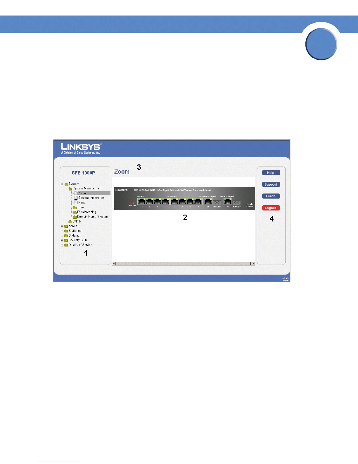
The following table lists the interface components with their corresponding numbers:
Interface Components
Component Description
1
Tree View The Tree View provides easy navigation through the configurable
2 Device View The device view provides information about device ports, current
Chapter 2: Getting Started
Understanding the Interface
device features.The main branches expand to provide the subfeatures.
configuration and status, table information, and feature
components.The device view also displays other device information
and dialog boxes for configuring parameters.
4
Page 13
Chapter
SFE1000P Gigabit Ethernet Switch Reference Guide
Component Description
3 Table Area The Table area enables navigating through the different device
features. Click the tabs to view all the components under a specific
feature.
4 EWS Information The EWS information tabs provide access to the online help, contains
information about the EWS.
Linksys User Interface Components
2
This section provides the following additional information:
•
Device Representation — Provides an explanation of the Linksys user interface buttons, including both
management buttons and task icons.
•
Using the Linksys Management Buttons — Provides instructions for adding, modifying, and deleting
device parameters.
Chapter 2: Getting Started
Understanding the Interface
5
Page 14
Chapter
SFE1000P Gigabit Ethernet Switch Reference Guide
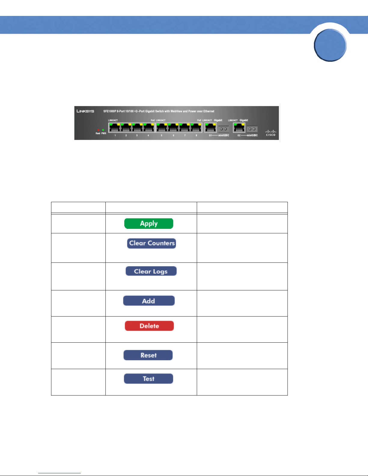
Device Representation
The Linksys home page displays a graphical representation of the device:
Device Representation
The Linksys home page contains a graphical SFE1000 and SFE1000P front panel illustration.
Using the Linksys Management Buttons
Device Management buttons and icons provide an easy method of configuring device information,
and include the following:
Device Management Buttons
Button Name Button Description
2
Apply Applies changes to the device.
Clear Counters Clears statistic counters
Clear Logs Clears log files
Add Opens an Add page
Delete Removes entries from tables
Reset Resets the settlings of a selected
port to the default settings
Test Performs cable tests immediately.
Chapter 2: Getting Started
Using the Linksys Management Buttons
6
Page 15

Chapter
SFE1000P Gigabit Ethernet Switch Reference Guide
Using Screen and Table Options
Linksys contains screens and tables for configuring devices. This section contains the following
topics:
•Adding Device Information
• Modifying Device Information
• Deleting Device Information
Adding Device Information
User defined information can be added to specific EWS pages, by opening a new Add page.
Add SNTP Server
2
Modifying Device Information
User defined information can be modified on specific EWS pages, by opening the appropriate Edit
page.
Edit Interface Priority
Deleting Device Information
User defined information can be deleted on specific EWS pages, by opening the appropriate EWS
page, selecting a table row, checking the remove checkbox, and then clicking the Delete button.
Chapter 2: Getting Started
Using Screen and Table Options
7
Page 16
Chapter
SFE1000P Gigabit Ethernet Switch Reference Guide
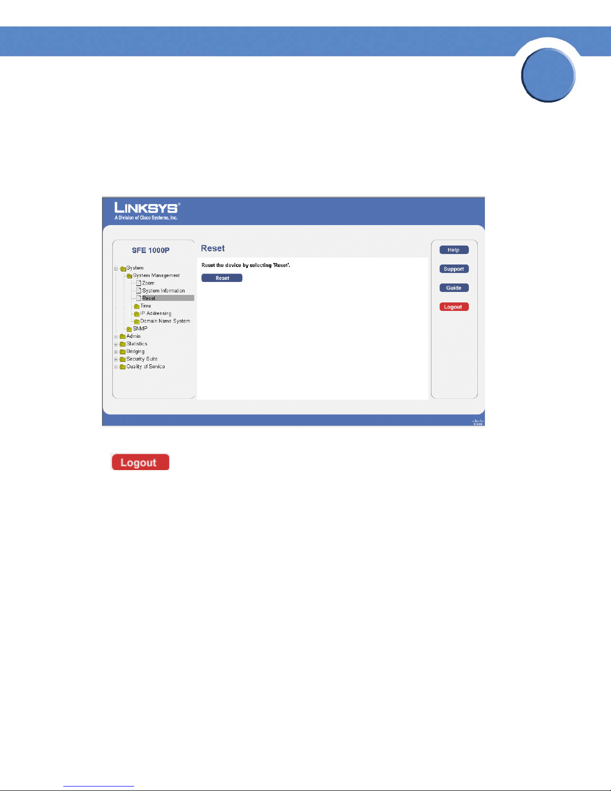
Resetting the Device
The Reset page enables the device to be reset from a remote location. Save all changes to the
Running Configuration file before resetting the device. This prevents the current device configuration
from being lost. To reset the device:
Reset Page
2
Logging Off The Device
Click . The system logs off. The Embedded Web System Home Page closes.
Chapter 2: Getting Started
Resetting the Device
8
Page 17
Chapter
SFE1000P Gigabit Ethernet Switch Reference Guide
Managing Device Information
This section provides information for defining both basic and advanced system information. This
section contains the following topics:
• Understanding the Device Zoom View
• Defining General System Information
• Resetting the Device
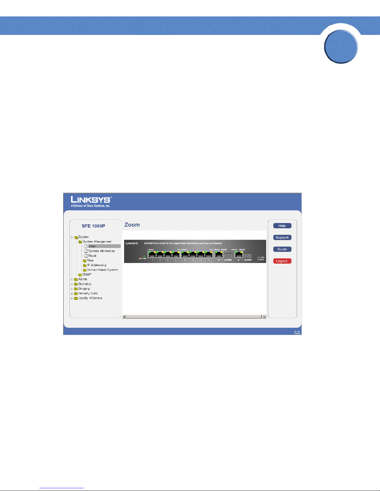
Understanding the Device Zoom View
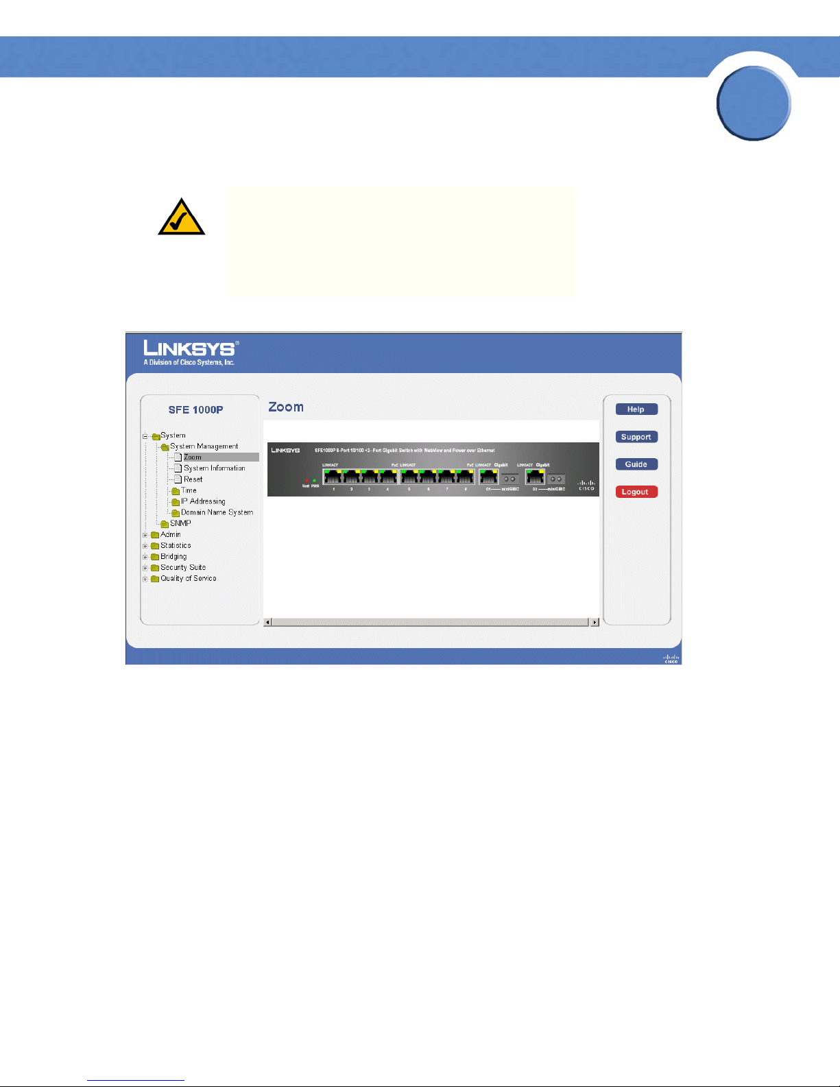
The Zoom Page is the main window used for viewing the device.
Zoom Page
3
The Zoom Page contains the following port indicators:
• Green — Indicates the port is currently operating.
Chapter 3: Managing Device Information
Understanding the Device Zoom View
9
Page 18
Chapter
SFE1000P Gigabit Ethernet Switch Reference Guide
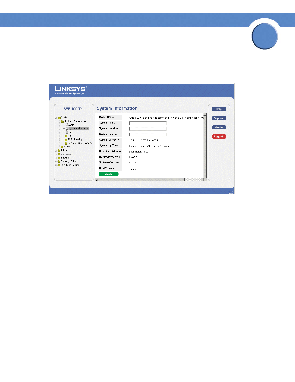
Defining General System Information
The System Information Page contains parameters for configuring general device information.
System Information Page
3
The System Information Page contains the following fields:
• Model Name — Displays the model name of the system.
• System Name — Displays the user configured name of the system.
• System Location — Defines the location where the system is currently running. The field
range is up-to 0-160 Characters.
• System Contact — Defines the name of the contact person.The field range is up to 0-160
Characters.
• System Object ID— Displays the vendor’s authoritative identification of the network
management subsystem contained in the entity.
• System Up Time — Displays the amount of time that has elapsed since the last device reset.
The system time is displayed in the following format: Days, Hours, Minutes and Seconds. For
example: 41 days, 2 hours, 22 minutes and 15 seconds.
• Base MAC Address — Displays the device MAC address.
• Hardware Version — Displays the hardware version number.
• Software Version — Displays the software version number.
• Boot Version — Indicates the system boot version currently running on the device.
Chapter 3: Managing Device Information
Defining General System Information
10
Page 19
Chapter
SFE1000P Gigabit Ethernet Switch Reference Guide
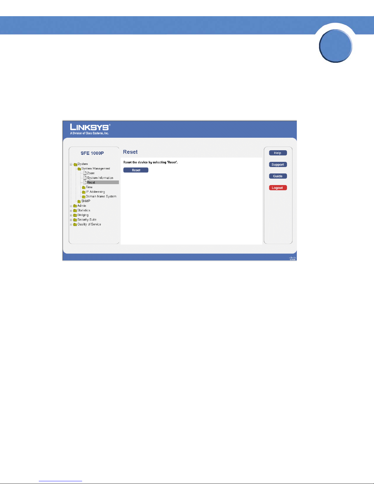
Resetting the Device
The Reset page enables the device to be reset from a remote location. Save all changes to the
Startup Configuration file before resetting the device. This prevents the current device configuration
from being lost.
Reset Page
3
Chapter 3: Managing Device Information
Resetting the Device
11
Page 20
Chapter
SFE1000P Gigabit Ethernet Switch Reference Guide
Managing Power-over-Ethernet Devices
Power-over-Ethernet (PoE) provides power to devices over existing LAN cabling, without updating or
modifying the network infrastructure. Power-over-Ethernet removes the necessity of placing network
devices next to power sources.
Power-over-Ethernet can be used in the following applications:
•IP Phones
• Wireless Access Points
•IP Gateways
•PDAs
• Audio and video remote monitoring
Powered Devices are devices which receive power from the device power supplies, for example IP
phones. Powered Devices are connected to the device via Ethernet ports. Guard Band protects the
device from exceeding the maximum power level. For example, if 400W is maximum power level,
and the Guard Band is 20W, if the total system power consumption exceeds 380W no additional
PoE components can be added. The accumulated PoE components power consumption is rounded
down for display purposes, therefore remove value after decimal point.
4
NOTE: Due to hardware limitations, the power
measurement accuracy is 4%.
Chapter 4: Managing Power-over-Ethernet Devices
12
Page 21

Chapter
SFE1000P Gigabit Ethernet Switch Reference Guide
PoE Settings
The PoE Settings Page contains system PoE information for enabling PoE on the device, monitoring
the current power usage, and enabling PoE traps.
PoE Settings Page
4
The PoE Settings Page displays the currently configured PoE ports and contains the following
information:
• Port — Displays the selected port’s number.
• Admin Status — Indicates whether PoE is enabled or disabled on the port. The possible
values are:
– Enable — Enables PoE on the port. This is the default setting.
– Disable — Disables PoE on the port.
• Priority — Indicates the PoE ports’ priority. The possible values are Critical, High and Low.
The default is Low.
• Power Allocation (watts) — Indicates the power allocated to the port. The range is 3 - 15.4
watts.
• Power Consumption (milliwatts) — Indicates the amount of power assigned to the powered
device connected to the selected interface. Devices are classified by the powered device,
and the classification information used. The field values are represented in Watts. The
possible field values are:
– 0.44 – 12.95 — Indicates that the port is assigned a power consumption level of .44 to
12.95 watts.
Chapter 4: Managing Power-over-Ethernet Devices
PoE Settings
13
Page 22

SFE1000P Gigabit Ethernet Switch Reference Guide
– 0.44 – 3.8 — Indicates that the port is assigned a power consumption level of .44 to 3.8
watts.
– 3.84 – 6.49 — Indicates that the port is assigned a power consumption level of 3.84 to
6.49 watts.
– 6.49 – 12.95 — Indicates that the port is assigned a power consumption level of 6.49 to
12.95 watts.
Edit PoE
Use the Edit PoE page to change settings for your devices.
Edit PoE
Chapter
4
The Edit PoE contains the following fields:
• Port — Indicates the specific interface for which PoE parameters are defined, and assigned
to the powered interface connected to the selected port.
• Enable PoE — Enables or disables PoE on the port. The possible values are:
– Enable — Enables PoE on the port. This is the default setting.
– Disable — Disables PoE on the port.
• Power Priority Level — Determines the port priority if the power supply is low. The port
power priority is used if the power supply is low. The field default is low. For example, if the
power supply is running at 99% usage, and port 1 is prioritized as high, but port 3 is
prioritized as low, port 1 is prioritized to receive power, and port 3 may be denied power.
The possible field values are:
– Low — Defines the PoE priority level as low. This is the default level.
Chapter 4: Managing Power-over-Ethernet Devices
PoE Settings
14
Page 23

Chapter
SFE1000P Gigabit Ethernet Switch Reference Guide
– High — Defines the PoE priority level as high.
– Critical — Defines the PoE priority level as Critical. This is the highest PoE priority level.
• Power Consumption — Indicates the amount of power assigned to the powered device
connected to the selected interface. Devices are classified by the powered device, and the
classification information used. The field values are represented in Watts. The possible field
values are:
– 0.44 – 12.95 — Indicates that the port is assigned a power consumption level of 0.44 to
12.95 Watts.
– 0.44 – 3.8 — Indicates that the port is assigned a power consumption level of 0.44 to
3.8 Watts.
– 3.84 – 6.49 — Indicates that the port is assigned a power consumption level of 3.84 to
6.49 Watts.
– 6.49 – 12.95 — Indicates that the port is assigned a power consumption level of 6.49 to
12.95 Watts.
4
• Overload Counter — Indicates the total power overload occurrences.
• Short Counter — Indicates the total power shortage occurrences.
• Denied Counter — Indicates times the powered device was denied power.
• Absent Counter — Indicates the times the power supply was stopped to the powered device
because the powered device was no longer detected.
• Invalid Signature Counter — Indicate the times an invalid signature was received.
Signatures are the means by which the powered device identifies itself to the PSE. Signature
are generated during powered device detection, classification, or maintenance.
• Power Allocation — Indicates the power allocated to the port. The range is 3 - 15.4 watts.
Chapter 4: Managing Power-over-Ethernet Devices
PoE Settings
15
Page 24
SFE1000P Gigabit Ethernet Switch Reference Guide
Configuring Device Security
The Security Suite contains the following sections:
• Passwords Management
• Defining Authentication
• Defining Access Method
• Defining Traffic Control
• Defining 802.1x
• Defining Access Control
• Defining DoS Prevention
Passwords Management
Chapter
5
This section contains information for defining passwords. Passwords are used to authenticate users
accessing the device.
NOTE: By default, a single user name is defined,
"admin", with no password. An additional user name/
password is configured for use in the system.
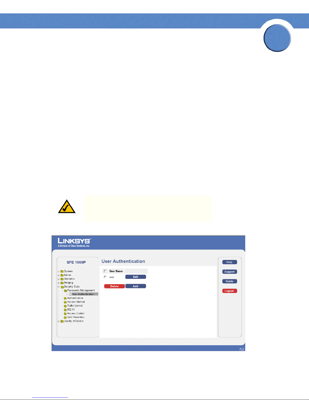
User Authentication Page
The User Authentication Page contains the following fields:
Chapter 5: Configuring Device Security
Passwords Management
16
Page 25
SFE1000P Gigabit Ethernet Switch Reference Guide
• User Name — Displays the user name.
• Edit — Click to modify the user name and/or password.
• Add — Click to add a new user.
• Delete — To delete a user name, select the user name and click the Delete button.
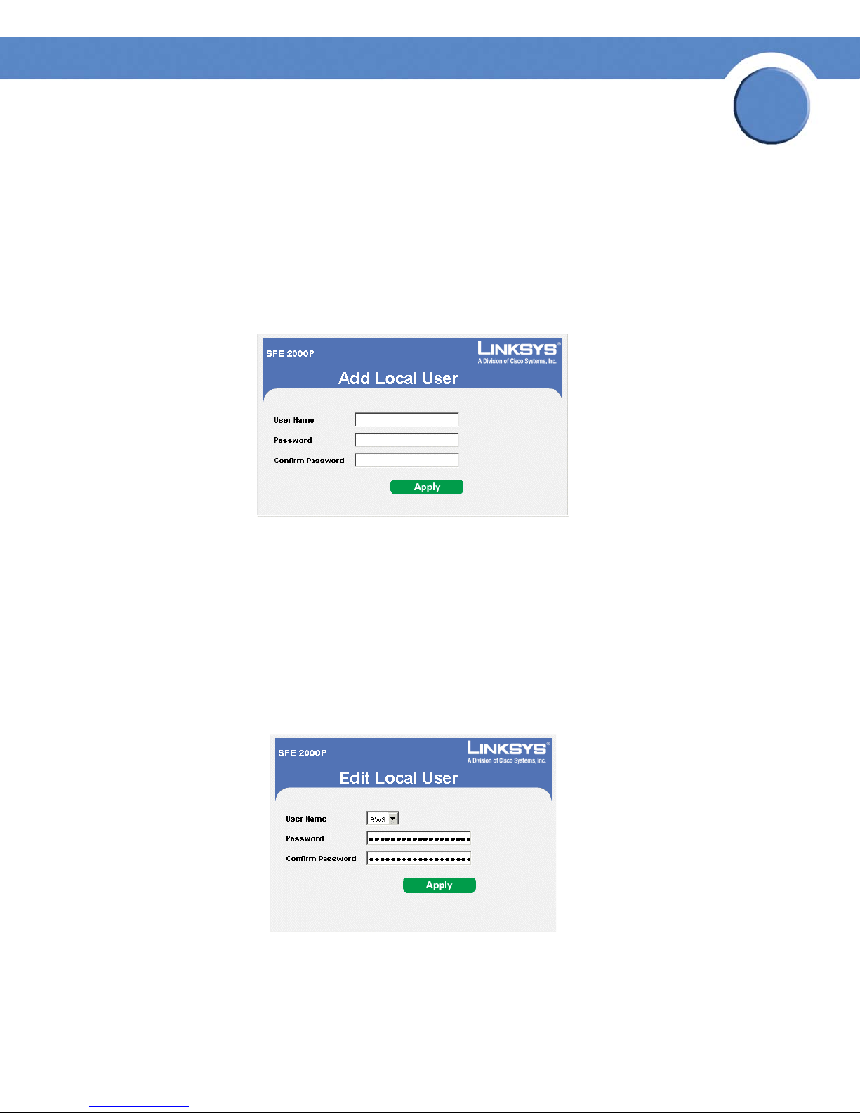
Add Local User
Add Local User Page
Chapter
5
The Add Local User Page contains the following fields:
• User Name — Displays the user name.
• Password — Specifies the new password. The is not displayed. As it entered an "*"
corresponding to each character is displayed in the field. (Range: 1-159 characters)
• Confirm Password — Confirms the new password. The password entered into this field must
be exactly the same as the password entered in the Password field.
Modifying the Local User Settings
Edit Local User Page
The Edit Local User Page contains the following fields:
• User Name — Displays the user name.
Chapter 5: Configuring Device Security
Passwords Management
17
Page 26
Chapter
SFE1000P Gigabit Ethernet Switch Reference Guide
• Password — Specifies the new password. The password is not displayed. As it entered an
"*" corresponding to each character is displayed in the field. (Range: 1-159 characters)
• Confirm Password — Confirms the new password. The password entered into this field must
be exactly the same as the password entered in the Password field.
Defining Authentication
The Authentication section contains the following pages:
• Defining Authentication Profiles
• Mapping Authentication Profiles
• Defining TACACS+
• Defining RADIUS
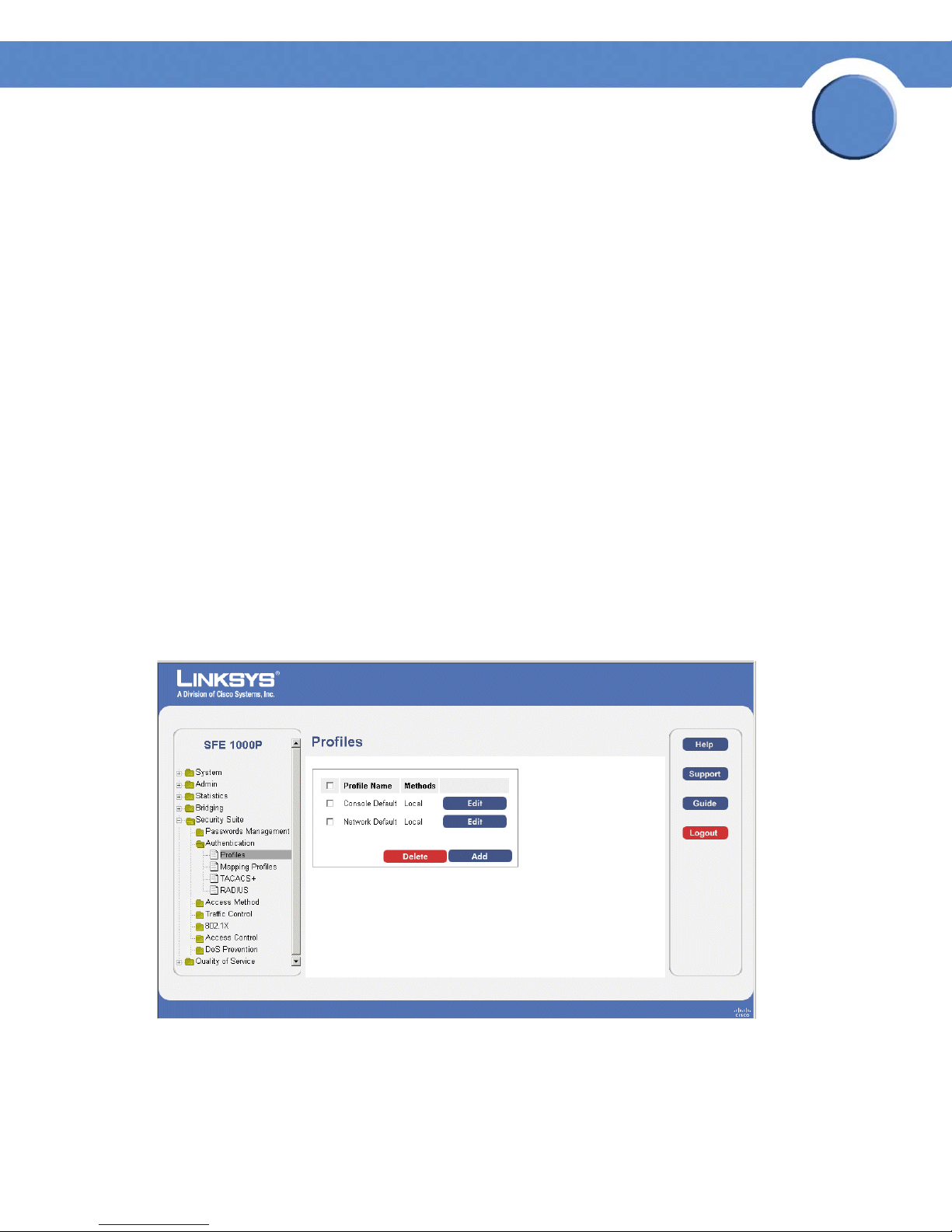
Defining Authentication Profiles
5
Authentication profiles allow network administrators to assign authentication methods for user
authentication. User authentication can be performed locally or on an external server. User
authentication occurs in the order the methods are selected. If the first authentication method is not
available, the next selected method is used. For example, if the selected authentication methods are
RADIUS and Local, and the RADIUS server is not available, then the user is authenticated locally.
Profiles Page
The Profiles Page contains the following fields:
• Profile Name — Displays the Profile name defined for the Login Table.
Chapter 5: Configuring Device Security
Defining Authentication
18
Page 27
Chapter
SFE1000P Gigabit Ethernet Switch Reference Guide
• Methods — Specifies the authentication method used for port authentication. The possible
field values are:
– Local — Authenticates the user at the device level. The device checks the user name and
password for authentication.
– RADIUS — Authenticates the user at the RADIUS server.
– TACACS+ — Authenticates the user at the TACACS+ server.
– None — Indicates that no authentication method is used to authenticate the port.
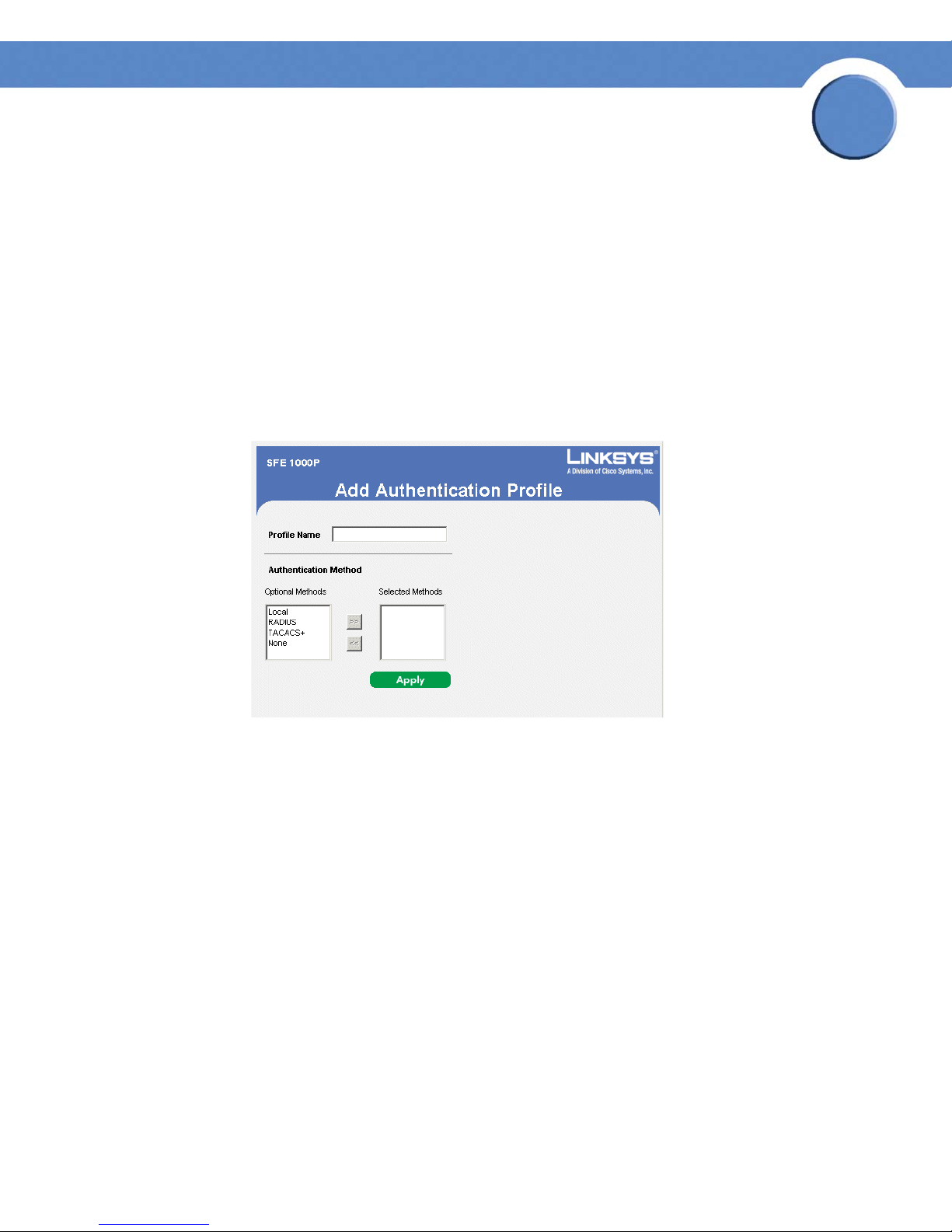
Add Authentication Profile
Add Authentication Profile Page
5
The Add Authentication Profile Page contains the following fields:
• Profile Name — Displays the Authentication profile name.
• Authentication Method — Defines the user authentication methods. The order of the
authentication methods indicates the order in which authentication is attempted. For
example, if the authentication method order is RADIUS, Local, the system first attempts to
authenticate the user on a RADIUS server. If there is no available RADIUS server, then
authentication is attempted on the local data base. Note that if the RADIUS server is
available, but authentication fails, then the user is denied access. The possible field values
are:
– Local — Authenticates the user at the device level. The device checks the user name and
password for authentication.
– RADIUS — Authenticates the user at the RADIUS server.
– TACACS+ — Authenticates the user at the TACACS+ server.
– None — Indicates that no authentication method is used to authenticate the port.
Chapter 5: Configuring Device Security
Defining Authentication
19
Page 28
SFE1000P Gigabit Ethernet Switch Reference Guide
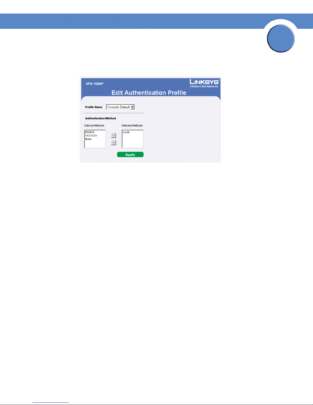
Modify the Authentication Profile
Edit Authentication Profile Page
The Edit Authentication Profile Page contains the following fields:
Chapter
5
• Profile Name — Displays the Authentication profile name.
• Authentication Methods — Defines the user authentication methods. The possible field
values are:
– Local — Authenticates the user at the device level. The device checks the user name and
password for authentication.
– RADIUS — Authenticates the user at the RADIUS server.
– TACACS+ — Authenticates the user at the TACACS+ server.
– None — No user authentication is attempted.
Chapter 5: Configuring Device Security
Defining Authentication
20
Page 29
Chapter
SFE1000P Gigabit Ethernet Switch Reference Guide
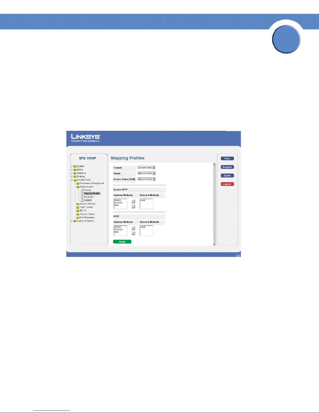
Mapping Authentication Profiles
After authentication profiles are defined, they can be applied to management access methods. For
example, console users can be authenticated by one authentication profile, while Telnet users are
authenticated by another authentication profile.
Authentication methods are selected using arrows. The order in which the methods are selected is
the order by which the authentication methods are used.
The Mapping Profiles Page contains parameters for mapping authentication methods.
Mapping Profiles Page
5
The Mapping Profiles Page contains the following fields:
• Console — Indicates that Authentication profiles are used to authenticate console users.
• Tel ne t — Indicates that Authentication profiles are used to authenticate Telnet users.
• Secure Telnet (SSH) — Indicates that Authentication profiles are used to authenticate Secure
Shell (SSH) users. SSH provides clients secure and encrypted remote connections to a
device.
• Secure HTTP — Configures the device Secure HTTP settings.
– Optional Methods — Lists available authentication methods.
– Local — Authenticates the user at the device level. The device checks the user name and
password for authentication.
– RADIUS — Remote Authorization Dial-In User Service (RADIUS) servers provide
additional security for networks.
Chapter 5: Configuring Device Security
Defining Authentication
21
Page 30

Chapter
SFE1000P Gigabit Ethernet Switch Reference Guide
– TACACS+ — Terminal Access Controller Access Control System (TACACS+) provides
centralized security user access validation.
– None — Indicates that no authentication method is used to authenticate the port.
• Selected Methods — Selects authentication methods from the methods offered in the
Optional methods area.
• HTTP — Configures the device HTTP settings.
• Optional Methods — Lists available authentication methods.
– Local — Authenticates the user at the device level. The device checks the user name and
password for authentication.
– RADIUS — Remote Authorization Dial-In User Service (RADIUS) servers provide
additional security for networks.
– TACACS+ — Terminal Access Controller Access Control System (TACACS+) provides
centralized security user access validation.
5
– None — Indicates that no authentication method is used to authenticate the port.
• Selected Methods — Selects authentication methods from the methods offered in the
Optional methods area.
Defining TACACS+
The devices provide Terminal Access Controller Access Control System (TACACS+) client support.
TACACS+ provides centralized security for validation of users accessing the device. TACACS+
provides a centralized user management system, while still retaining consistency with RADIUS and
other authentication processes. TACACS+ provides the following services:
• Authentication — Provides authentication during login and via user names and userdefined passwords.
• Authorization — Performed at login. Once the authentication session is completed, an
authorization session starts using the authenticated user name. The TACACS server checks
the user privileges.
The TACACS+ protocol ensures network integrity through encrypted protocol exchanges between
the device and TACACS+ server.
The TACACS+ default parameters are user-assigned defaults. The default settings are applied to
newly defined TACACS+ servers. If default values are not defined, the system defaults are applied to
the new TACACS+ new servers. The TACACS+ Page contains fields for assigning the Default
Parameters for the TACACS+ servers.
Chapter 5: Configuring Device Security
Defining TACACS+
22
Page 31
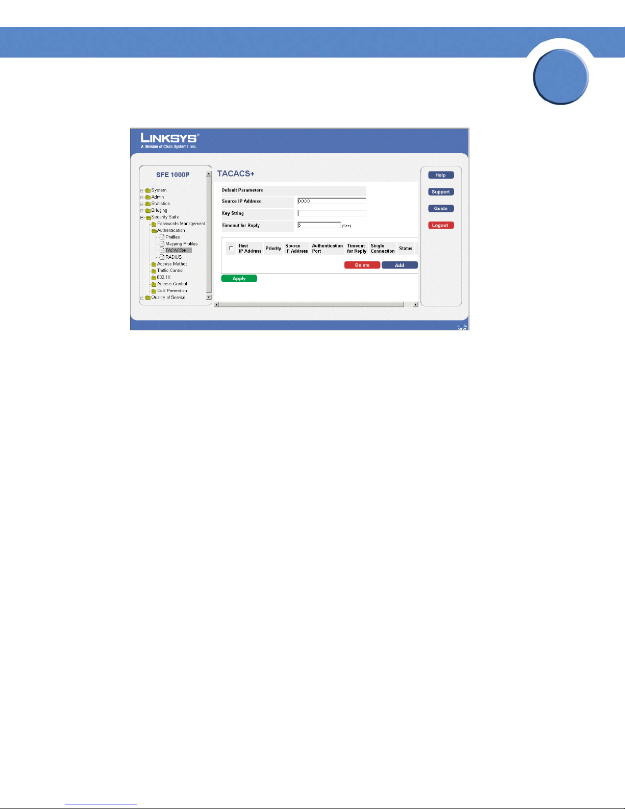
TACACS+ Page
The TACACS+ Page contains the following fields:
Chapter
SFE1000P Gigabit Ethernet Switch Reference Guide
5
• Source IP Address — Displays the device source IP address used for the TACACS+ session
between the device and the TACACS+ server.
• Key String — Defines the authentication and encryption key for TACACS+ server. The key
must match the encryption key used on the TACACS+ server.
• Timeout for Reply — Displays the amount of time that passes before the connection between
the device and the TACACS+ server times out. The field range is 1-30 seconds.
The following parameters are configured for each TACACS+ server:
• Host IP Address — Displays the TACACS+ Server IP address.
• Priority — Displays the order in which the TACACS+ servers are used. The default is 0.
• Source IP Address — Displays the device source IP address used for the TACACS+ session
between the device and the TACACS+ server.
• Authentication Port — Displays the port number through which the TACACS+ session
occurs. The default is port 49.
• Timeout for Reply — Displays the amount of time in seconds that passes before the
connection between the device and the TACACS+ times out. The field range is 1-1000
seconds.
• Single Connection — Maintains a single open connection between the device and the
TACACS+ server when selected.
• Status — Displays the connection status between the device and the TACACS+ server. The
possible field values are:
Chapter 5: Configuring Device Security
Defining TACACS+
23
Page 32

– Connected — There is currently a connection between the device and the TACACS+
server.
– Not Connected — There is not currently a connection between the device and the
TACACS+ ser ver.
Add TACACS+ Server
SFE1000P Gigabit Ethernet Switch Reference Guide
Add TACACS+ Server Page
Chapter
5
The Add TACACS+ Server Page contains the following fields:
• Host IP Address — Displays the TACACS+ Server IP address.
• Priority — Displays the order in which the TACACS+ servers are used. The default is 0.
• Source IP Address — Defines the device source IP address used for the TACACS+ session
between the device and the TACACS+ server.
• Key String — Defines the authentication and encryption key for TACACS+ server. The key
must match the encryption key used on the TACACS+ server.
• Authentication Port — Displays the port number through which the TACACS+ session
occurs. The default is port 49.
• Timeout for Reply — Defines the amount of time that passes before the connection between
the device and the TACACS+ server times out. The field range is 1-30 seconds.
• Single Connection — Maintains a single open connection between the device and the
TACACS+ server when selected.
• Use Default — Uses the default value for the parameter.
Chapter 5: Configuring Device Security
Defining TACACS+
24
Page 33

Modifying TACACS+ Settings
SFE1000P Gigabit Ethernet Switch Reference Guide
TACACS+ Page
Chapter
5
The TACACS+ Page contains the following fields:
• Host IP Address — Displays the TACACS+ Server IP address.
• Priority — Displays the order in which the TACACS+ servers are used. The default is 0.
• Source IP Address — Defines the device source IP address used for the TACACS+ session
between the device and the TACACS+ server.
• Key String — Defines the authentication and encryption key for TACACS+ server. The key
must match the encryption key used on the TACACS+ server.
• Authentication Port — Displays the port number through which the TACACS+ session
occurs. The default is port 49.
• Timeout for Reply — Defines the amount of time that passes before the connection between
the device and the TACACS+ server times out. The field range is 1-30 seconds.
• Status — Displays the connection status between the device and the TACACS+ server. The
possible field values are:
– Connected — There is currently a connection between the device and the TACACS+
server.
– Not Connected — There is not currently a connection between the device and the
TACACS+ ser ver.
• Single Connection — Maintains a single open connection between the device and the
TACACS+ server when selected.
• Use Default — Uses the default value for the parameter.
Chapter 5: Configuring Device Security
Defining TACACS+
25
Page 34

Chapter
SFE1000P Gigabit Ethernet Switch Reference Guide
Defining RADIUS
Remote Authorization Dial-In User Service (RADIUS) servers provide additional security for
networks. RADIUS servers provide a centralized authentication method for web access. The default
parameters are user-defined, and are applied to newly defined RADIUS servers. If new default
parameters are not defined, the system default values are applied to newly defined RADIUS servers.
RADIUS Page
5
The RADIUS Page contains the following fields:
• Default Retries — Provides the default retries.
• Default Timeout for Reply — Provides the device default Timeout for Reply.
• Default Dead Time — Provides the device default Dead Time.
• Default Key String — Provides the device default Default Key String.
• Source IP Address — Provides the device default Timeout for Reply.
The following parameters are configured for each RADIUS server:
• IP Address — The Authentication Server IP addresses.
• Priority — The server priority. The possible values are 0-65535, where 1 is the highest
value. The RADIUS Server priority is used to configure the server query order.
• Authentication Port — Identifies the authentication port. The authentication port is used to
verify the RADIUS server authentication. The authenticated port default is 1812.
Chapter 5: Configuring Device Security
Defining RADIUS
26
Page 35

Chapter
SFE1000P Gigabit Ethernet Switch Reference Guide
• Number of Retries — Defines the number of transmitted requests sent to RADIUS server
before a failure occurs. The possible field values are 1 - 10. Three is the default value.
• Timeout for Reply — Defines the amount of the time in seconds the device waits for an
answer from the RADIUS server before retrying the query, or switching to the next server.
The possible field values are 1 - 30. Three is the default value.
• Dead Time — Defines the amount of time (minutes) that a RADIUS server is bypassed for
service requests. The range is 0-2000. The Dead Time default is 0 minutes.
• Key String — Defines the default key string used for authenticating and encrypting all
RADIUS communications between the device and the RADIUS server. This key must match
the RADIUS encryption.
• Source IP Address — Defines the source IP address that is used for communication with
RADIUS servers.
• Usage Type — Specifies the RADIUS server authentication type. The default value is Login.
The possible field values are:
5
– Login — Indicates that the RADIUS server is used for authenticating user name and
passwords.
– 802.1X — Indicates that the RADIUS server is used for 802.1X authentication.
– All — Indicates that the RADIUS server is used for authenticating user name and
passwords, and 802.1X port authentication.
Add RADIUS Server
Add Radius Server Page
The Add Radius Server Page contains the following fields:
• Host IP Address — Displays the RADIUS Server IP address.
Chapter 5: Configuring Device Security
Defining RADIUS
27
Page 36

Chapter
SFE1000P Gigabit Ethernet Switch Reference Guide
• Priority — The server priority. The possible values are 0-65535, where 1 is the highest
value. The RADIUS Server priority is used to configure the server query order.
• Authentication Port — Identifies the authentication port. The authentication port is used to
verify the RADIUS server authentication. The authenticated port default is 1812.
• Number of Retries — Defines the number of transmitted requests sent to RADIUS server
before a failure occurs. The possible field values are 1 - 10. Three is the default value.
• Timeout for Reply — Defines the amount of the time in seconds the device waits for an
answer from the RADIUS server before retrying the query, or switching to the next server.
The possible field values are 1 - 30. Three is the default value.
• Dead Time — Defines the amount of time (minutes) that a RADIUS server is bypassed for
service requests. The range is 0-2000. The Dead Time default is 0 minutes.
• Key String — Defines the default key string used for authenticating and encrypting all
RADIUS communications between the device and the RADIUS server. This key must match
the RADIUS encryption.
5
• Source IP Address — Defines the source IP address that is used for communication with
RADIUS servers.
• Usage Type — Specifies the RADIUS server authentication type. The default value is Login.
The possible field values are:
– Login — Indicates that the RADIUS server is used for authenticating user name and
passwords.
– 802.1X — Indicates that the RADIUS server is used for 802.1X authentication.
– All — Indicates that the RADIUS server is used for authenticating user name and
passwords, and 802.1X port authentication.
• Use Default — Uses the default value for the parameter.
Chapter 5: Configuring Device Security
Defining RADIUS
28
Page 37

Modifying RADIUS Server Settings
Edit RADIUS Settings Page
Chapter
SFE1000P Gigabit Ethernet Switch Reference Guide
5
The Edit RADIUS Settings Page contains the following fields:
• IP Address — Displays the RADIUS Server IP address.
• Priority — The server priority. The possible values are 0-65535, where 1 is the highest
value. The RADIUS Server priority is used to configure the server query order.
• Authentication Port — Identifies the authentication port. The authentication port is used to
verify the RADIUS server authentication. The authenticated port default is 1812.
• Number of Retries — Defines the number of transmitted requests sent to RADIUS server
before a failure occurs. The possible field values are 1 - 10. Three is the default value.
• Timeout for Reply — Defines the amount of the time in seconds the device waits for an
answer from the RADIUS server before retrying the query, or switching to the next server.
The possible field values are 1 - 30. Three is the default value.
• Dead Time — Defines the amount of time (minutes) that a RADIUS server is bypassed for
service requests. The range is 0-2000. The Dead Time default is 0 minutes.
• Key String — Defines the default key string used for authenticating and encrypting all
RADIUS communications between the device and the RADIUS server. This key must match
the RADIUS encryption.
• Source IP Address — Defines the source IP address that is used for communication with
RADIUS servers.
• Usage Type — Specifies the RADIUS server authentication type. The default value is Login.
The possible field values are:
Chapter 5: Configuring Device Security
Defining RADIUS
29
Page 38

SFE1000P Gigabit Ethernet Switch Reference Guide
– Login — Indicates that the RADIUS server is used for authenticating user name and
passwords.
– 802.1X — Indicates that the RADIUS server is used for 802.1X authentication.
– All — Indicates that the RADIUS server is used for authenticating user name and
passwords, and 802.1X port authentication.
• Use Default — Uses the default value for the parameter.
Defining Access Method
The access method section contains the following pages:
• Defining Access Profiles
• Defining Profile Rules
Defining Access Profiles
Chapter
5
Access profiles are profiles and rules for accessing the device. Access to management functions can
be limited to user groups. User groups are defined for interfaces according to IP addresses or IP
subnets. Access profiles contain management methods for accessing and managing the device. The
device management methods include:
•All
•Telnet
• Secure Telnet (SSH)
• HTTP
• Secure HTTP (HTTPS)
•SNMP
Management access to different management methods may differ between user groups. For
example, User Group 1 can access the switch module only via an HTTPS session, while User Group
2 can access the switch module via both HTTPS and Telnet sessions. The Access Profile Page contains
the currently configured access profiles and their activity status. Assigning an access profile to an
interface denies access via other interfaces. If an access profile is assigned to any interface, the
device can be accessed by all interfaces.
Chapter 5: Configuring Device Security
Defining Access Method
30
Page 39
SFE1000P Gigabit Ethernet Switch Reference Guide
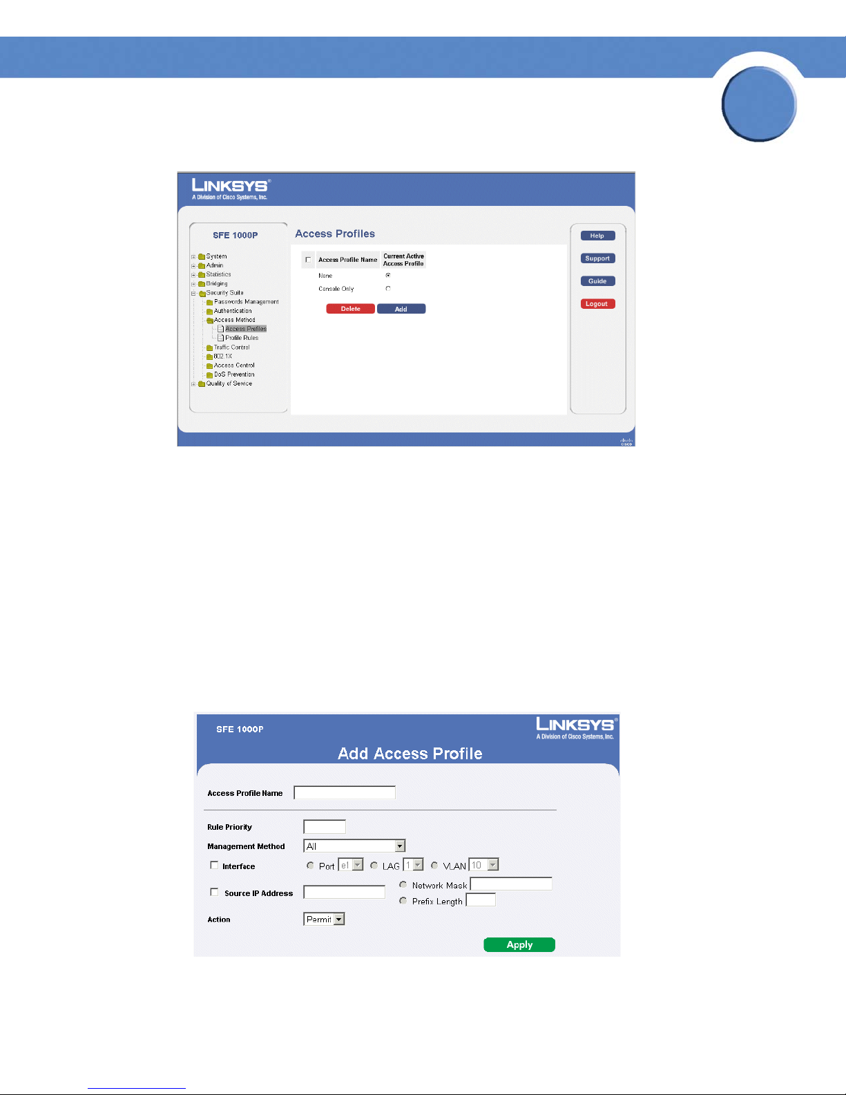
Access Profiles Page
Chapter
5
The Access Profiles Page contains the following fields:
• Access Profile Name — Defines the access profile name. The access profile name can
contain up to 32 characters.
• Current Active Access Profile — Defines the access profile currently active.
• Delete — Deletes the selected access profile. The possible field values are:
– Checked — Deletes the selected access profile.
– Unchecked — Maintains the access profiles.
Add Access Profile Page
Add Access Profile Page
The Add Access Profile Page contains the following fields:
Chapter 5: Configuring Device Security
Defining Access Method
31
Page 40

Chapter
SFE1000P Gigabit Ethernet Switch Reference Guide
• Access Profile Name — Defines the access profile name. The access profile name can
contain up to 32 characters.
• Rule Priority — Defines the rule priority. When the packet is matched to a rule, user groups
are either granted permission or denied device management access. The rule number is
essential to matching packets to rules, as packets are matched on a first-fit basis. The rule
priorities are assigned in the Profile Rules Page.
• Management Method — Defines the management method for which the rule is defined.
Users with this access profile can access the device using the management method selected.
The possible field values are:
– All — Assigns all management methods to the rule.
– Tel net — Assigns Telnet access to the rule. If selected, users accessing the device using
Telnet meeting access profile criteria are permitted or denied access to the device.
– Secure Telnet (SSH) — Assigns SSH access to the rule. If selected, users accessing the
device using Telnet meeting access profile criteria are permitted or denied access to the
device.
5
– HTTP — Assigns HTTP access to the rule. If selected, users accessing the device using
HTTP meeting access profile criteria are permitted or denied access to the device.
– Secure HTTP (HTTPS) — Assigns HTTPS access to the rule. If selected, users accessing the
device using HTTPS meeting access profile criteria are permitted or denied access to the
device.
– SNMP — Assigns SNMP access to the rule. If selected, users accessing the device using
SNMP meeting access profile criteria are permitted or denied access to the device.
• Interface — Defines the interface on which the access profile is defined. The possible field
values are:
– Port — Specifies the port on which the access profile is defined.
– LAG — Specifies the LAG on which the access profile is defined.
– VLAN — Specifies the VLAN on which the access profile is defined.
• Source IP Address — Defines the interface source IP address to which the access profile
applies. The Source IP Address field is valid for a subnetwork.
– Network Mask — Determines what subnet the source IP Address belongs to in the
network.
– Prefix Length — Defines the number of bits that comprise the source IP address prefix, or
the network mask of the source IP address.
• Action — Defines the action attached to the rule. The possible field values are:
– Permit — Permits access to the device.
Chapter 5: Configuring Device Security
Defining Access Method
32
Page 41

Chapter
SFE1000P Gigabit Ethernet Switch Reference Guide
– Deny — Denies access to the device. This is the default.
Defining Profile Rules
Access profiles can contain up to 128 rules that determine which users can manage the switch
module, and by which methods. Users can also be blocked from accessing the device. Rules are
composed of filters including:
• Rule Priority
•Interface
• Management Method
• IP Address
•Prefix Length
• Forwarding Action
5
Profile Rules Page
The Profile Rules Page contains the following fields:
• Access Profile Name — Displays the access profile to which the rule is attached.
• Priority — Defines the rule priority. When the packet is matched to a rule, user groups are
either granted permission or denied device management access. The rule number is
essential to matching packets to rules, as packets are matched on a first-fit basis.
• Interface — Indicates the interface type to which the rule applies. The possible field values
are:
– Port — Attaches the rule to the selected port.
– LAG — Attaches the rule to the selected LAG.
Chapter 5: Configuring Device Security
Defining Access Method
33
Page 42

Chapter
SFE1000P Gigabit Ethernet Switch Reference Guide
– VLAN — Attaches the rule to the selected VLAN.
• Management Method — Defines the management method for which the rule is defined.
Users with this access profile can access the device using the management method selected.
The possible field values are:
– All — Assigns all management methods to the rule.
– Tel net — Assigns Telnet access to the rule. If selected, users accessing the device using
Telnet meeting access profile criteria are permitted or denied access to the device.
– SNMP — Assigns SNMP access to the rule. If selected, users accessing the device using
SNMP meeting access profile criteria are permitted or denied access to the device.
– HTTP — Assigns HTTP access to the rule. If selected, users accessing the device using
HTTP meeting access profile criteria are permitted or denied access to the device.
– Secure HTTP (HTTPS) — Assigns HTTPS access to the rule. If selected, users accessing the
device using HTTPS meeting access profile criteria are permitted or denied access to the
device.
5
– Secure Telnet (SSH) — Assigns SSH access to the rule. If selected, users accessing the
device using Telnet meeting access profile criteria are permitted or denied access to the
device.
• Source IP Address — Defines the interface source IP address to which the rule applies.
• Prefix Length — Defines the number of bits that comprise the source IP address prefix, or the
network mask of the source IP address.
• Action — Defines the action attached to the rule. The possible field values are:
– Permit — Permits access to the device.
– Deny — Denies access to the device. This is the default.
Chapter 5: Configuring Device Security
Defining Access Method
34
Page 43
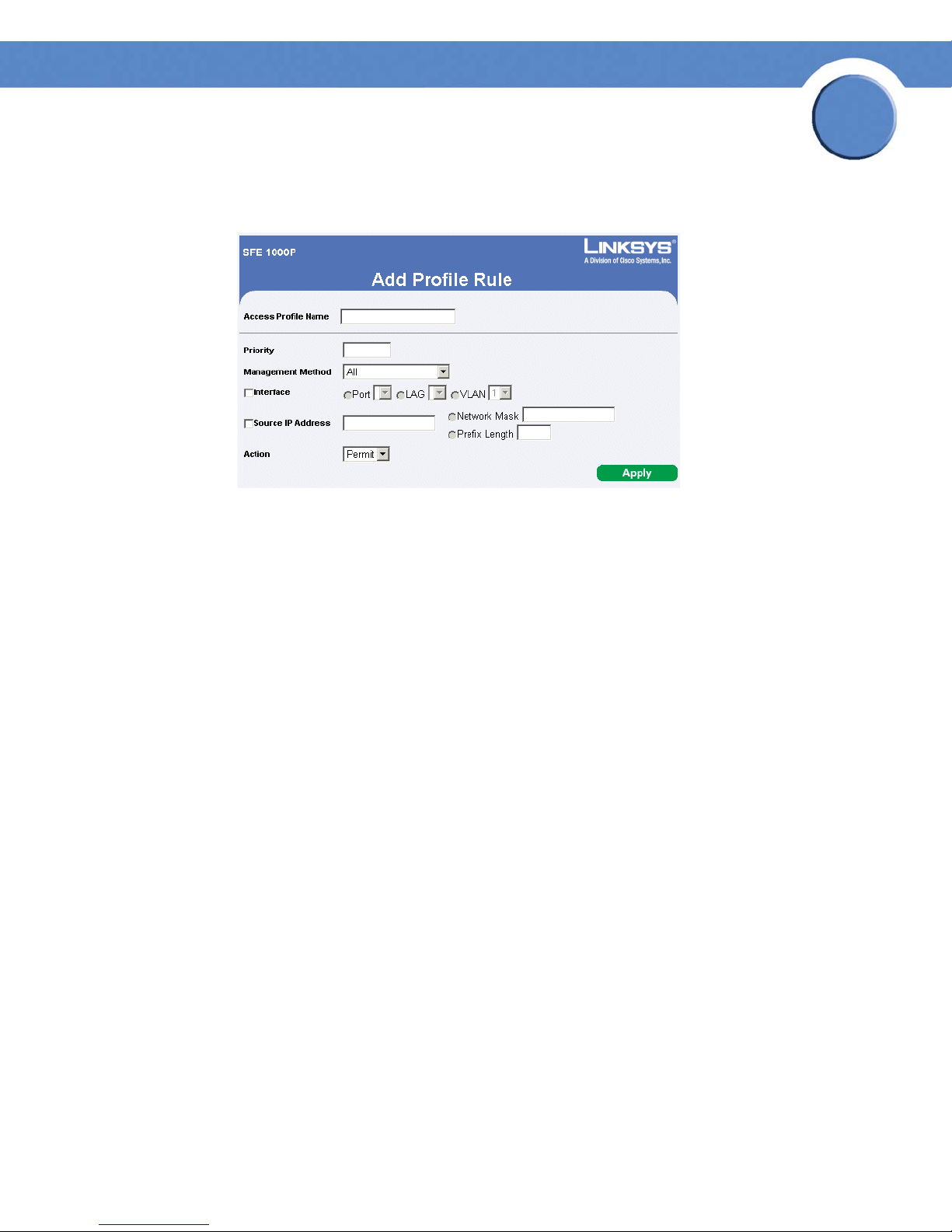
Add Profile Rule
Add Profile Rule Page
The Add Profile Rule Page contains the following fields:
Chapter
SFE1000P Gigabit Ethernet Switch Reference Guide
5
• Access Profile Name — Defines the access profile name. The access profile name can
contain up to 32 characters.
• Priority — Defines the rule priority. When the packet is matched to a rule, user groups are
either granted permission or denied device management access. The rule number is
essential to matching packets to rules, as packets are matched on a first-fit basis. The rule
priorities are assigned in the Profile Rules Page.
• Management Method — Defines the management method for which the rule is defined.
Users with this access profile can access the device using the management method selected.
The possible field values are:
– All — Assigns all management methods to the rule.
– Tel net — Assigns Telnet access to the rule. If selected, users accessing the device using
Telnet meeting access profile criteria are permitted or denied access to the device.
– SNMP — Assigns SNMP access to the rule. If selected, users accessing the device using
SNMP meeting access profile criteria are permitted or denied access to the device.
– HTTP — Assigns HTTP access to the rule. If selected, users accessing the device using
HTTP meeting access profile criteria are permitted or denied access to the device.
– Secure HTTP (SSL) — Assigns HTTPS access to the rule. If selected, users accessing the
device using HTTPS meeting access profile criteria are permitted or denied access to the
device.
– Secure Telnet (SSH) — Assigns SSH access to the rule. If selected, users accessing the
device using Telnet meeting access profile criteria are permitted or denied access to the
device.
Chapter 5: Configuring Device Security
Defining Access Method
35
Page 44

Chapter
SFE1000P Gigabit Ethernet Switch Reference Guide
• Interface — Defines the interface on which the access profile is defined. The possible field
values are:
– Port — Specifies the port on which the access profile is defined.
– LAG — Specifies the LAG on which the access profile is defined.
– VLAN — Specifies the VLAN on which the access profile is defined.
• Source IP Address — Defines the interface source IP address to which the access profile
applies. The Source IP Address field is valid for a subnetwork.
– Network Mask — Determines what subnet the source IP Address belongs to in the
network.
– Prefix Length — Defines the number of bits that comprise the source IP address prefix, or
the network mask of the source IP address.
• Action — Defines the action attached to the rule. The possible field values are:
5
– Permit — Permits access to the device.
– Deny — Denies access to the device. This is the default.
Modifying Profile Rules
Edit Profile Rule Page
The Edit Profile Rule Page contains the following fields:
• Access Profile Name — Defines the access profile name. The access profile name can
contain up to 32 characters.
• Priority — Defines the rule priority. When the packet is matched to a rule, user groups are
either granted permission or denied device management access. The rule number is
essential to matching packets to rules, as packets are matched on a first-fit basis. The rule
priorities are assigned in the Profile Rules Page.
Chapter 5: Configuring Device Security
Defining Access Method
36
Page 45

Chapter
SFE1000P Gigabit Ethernet Switch Reference Guide
• Management Method — Defines the management method for which the rule is defined.
Users with this access profile can access the device using the management method selected.
The possible field values are:
– All — Assigns all management methods to the rule.
– Tel net — Assigns Telnet access to the rule. If selected, users accessing the device using
Telnet meeting access profile criteria are permitted or denied access to the device.
– SNMP — Assigns SNMP access to the rule. If selected, users accessing the device using
SNMP meeting access profile criteria are permitted or denied access to the device.
– HTTP — Assigns HTTP access to the rule. If selected, users accessing the device using
HTTP meeting access profile criteria are permitted or denied access to the device.
– Secure HTTP (SSL) — Assigns HTTPS access to the rule. If selected, users accessing the
device using HTTPS meeting access profile criteria are permitted or denied access to the
device.
– Secure Telnet (SSH) — Assigns SSH access to the rule. If selected, users accessing the
device using Telnet meeting access profile criteria are permitted or denied access to the
device.
5
• Interface — Defines the interface on which the access profile is defined. The possible field
values are:
– Port — Specifies the port on which the access profile is defined.
– LAG — Specifies the LAG on which the access profile is defined.
– VLAN — Specifies the VLAN on which the access profile is defined.
• Source IP Address — Defines the interface source IP address to which the access profile
applies. The Source IP Address field is valid for a subnetwork.
– Network Mask — Determines what subnet the source IP Address belongs to in the
network.
– Prefix Length — Defines the number of bits that comprise the source IP address prefix, or
the network mask of the source IP address.
• Action — Defines the action attached to the rule. The possible field values are:
– Permit — Permits access to the device.
– Deny — Denies access to the device. This is the default.
Chapter 5: Configuring Device Security
Defining Access Method
37
Page 46
Chapter
SFE1000P Gigabit Ethernet Switch Reference Guide
Defining Traffic Control
The Traffic Control section contains the following pages:
• Defining Storm Control
• Defining Port Security
Defining Storm Control
Storm Control enables limiting the amount of Multicast and Broadcast frames accepted and
forwarded by the device. When Layer 2 frames are forwarded, Broadcast and Multicast frames are
flooded to all ports on the relevant VLAN. This occupies bandwidth, and loads all nodes connected
on all ports.
A Broadcast Storm is a result of an excessive amount of broadcast messages simultaneously
transmitted across a network by a single port. Forwarded message responses are heaped onto the
network, straining network resources or causing the network to time out.
5
Storm Control is enabled per all ports by defining the packet type and the rate the packets are
transmitted. The system measures the incoming Broadcast and Multicast frame rates separately on
each port and discards the frames when the rate exceeds a user-defined rate.
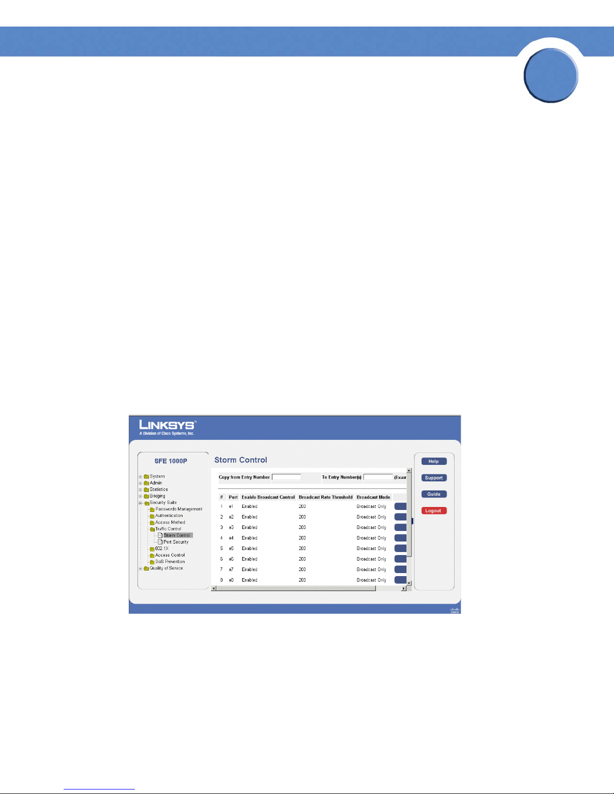
The Storm Control Page provides fields for configuring Broadcast Storm Control.
Storm Control Page
The Storm Control Page contains the following fields:
• Copy From Entry Number — Indicates the row number from which storm control
parameters are copied.
• To En tr y N um ber( s) — Indicates the row number to which storm control parameters are
copied.
Chapter 5: Configuring Device Security
Defining Traffic Control
38
Page 47
Chapter
SFE1000P Gigabit Ethernet Switch Reference Guide
• Port — Indicates the port from which storm control is enabled.
• Enable Broadcast Control — Indicates if Broadcast packet types are forwarded on the
specific interface. The possible field values are:
– Enable — Enables Broadcast packet types to be forwarded.
– Disable — Disables Broadcast packet types to be forwarded.
• Broadcast Rate Threshold — The maximum rate (kilobits per second) at which unknown
packets are forwarded.
– For FE ports, the rate is 70 - 100,000 Kbps.
– For GE ports, the rate is 35,000 - 100,000 Kbps.
• Broadcast Mode — Specifies the Broadcast mode currently enabled on the device. The
possible field values are:
– Multicast & Broadcast — Counts Broadcast and Multicast traffic together.
5
– Broadcast Only — Counts only Broadcast traffic.
Modifying Storm Control
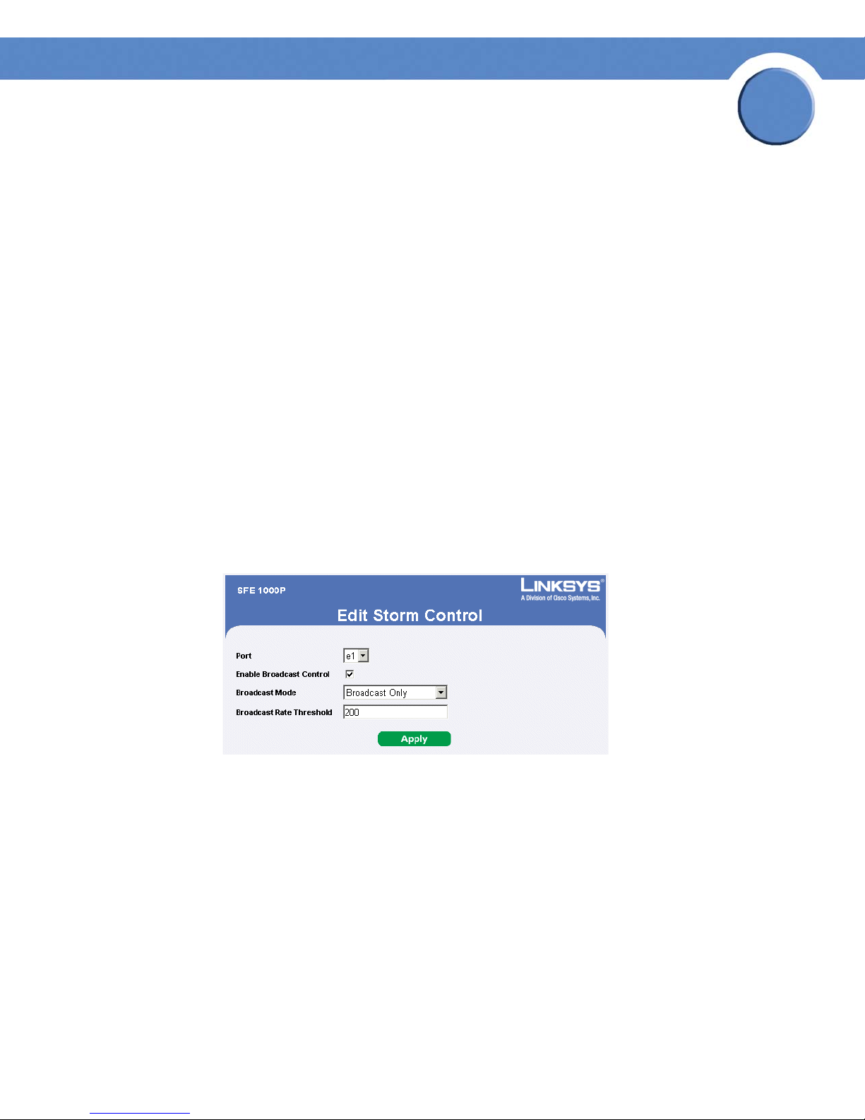
Edit Storm Control Page
The Edit Storm Control Page contains the following fields:
• Port — Indicates the port from which storm control is enabled.
• Enable Broadcast Control — Indicates if Broadcast packet types are forwarded on the
specific interface. The possible field values are:
– Checked — Enables Broadcast packet types to be forwarded.
– Unchecked — Disables Broadcast packet types to be forwarded.
• Broadcast Mode — Specifies the Broadcast mode currently enabled on the device. The
possible field values are:
– Multicast & Broadcast — Counts Broadcast and Multicast traffic together.
Chapter 5: Configuring Device Security
Defining Traffic Control
39
Page 48
Chapter
SFE1000P Gigabit Ethernet Switch Reference Guide
– Broadcast Only — Counts only Broadcast traffic.
• Broadcast Rate Threshold — The maximum rate (packets per second) at which unknown
packets are forwarded.
– For FE ports, the rate is 70 - 100,000 Kbps.
– For GE ports, the rate is 35,000 - 100,000 Kbps.
Defining Port Security
Network security can be increased by limiting access on a specific port only to users with specific
MAC addresses. The MAC addresses can be dynamically learned or statically configured. Locked
port security monitors both received and learned packets that are received on specific ports. Access
to the locked port is limited to users with specific MAC addresses. These addresses are either
manually defined on the port, or learned on that port up to the point when it is locked. When a
packet is received on a locked port, and the packet source MAC address is not tied to that port
(either it was learned on a different port, or it is unknown to the system), the protection mechanism is
invoked, and can provide various options. Unauthorized packets arriving at a locked port are
either:
5
•Forwarded
• Discarded with no trap
• Discarded with a trap
• Cause the port to be shut down.
Locked port security also enables storing a list of MAC addresses in the configuration file. The MAC
address list can be restored after the device has been reset. Disabled ports are activated from the
Port Management page.
NOTE: To configure port lock, 802.1x multiple host mode
must be enabled.
Chapter 5: Configuring Device Security
Defining Traffic Control
40
Page 49
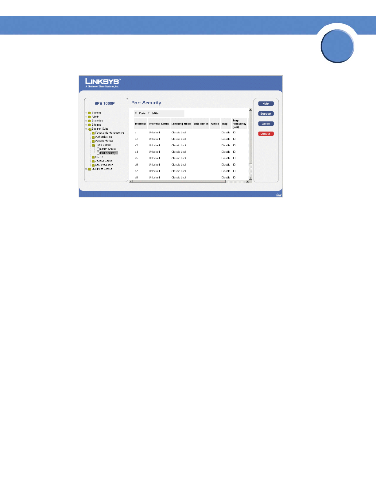
Port Security Page
The Port Security Page contains the following fields:
Chapter
SFE1000P Gigabit Ethernet Switch Reference Guide
5
• Ports — Indicates the port number on which port security is configured.
• LAGs — Indicates the LAG number on which port security is configured.
• Interface — Displays the port or LAG name.
• Interface Status — Indicates the port security status. The possible field values are:
– Unlocked — Indicates the port is currently unlocked. This is the default value.
– Locked — Indicates the port is currently locked.
• Learning Mode — Defines the locked port type. The Learning Mode field is enabled only if
Locked is selected in the Interface Status field.The possible field values are:
– Classic Lock — Locks the port using the classic lock mechanism. The port is immediately
locked, regardless of the number of addresses that have already been learned.
– Limited Dynamic Lock — Locks the port by deleting the current dynamic MAC addresses
associated with the port. The port learns up to the maximum addresses allowed on the
port. Both relearning and aging MAC addresses are enabled.
In order to change the Learning Mode, the Lock Interface must be set to Unlocked. Once the
mode is changed, the Lock Interface can be reinstated.
• Max Entries — Specifies the number of MAC addresses that can be learned on the port. The
Max Entries field is enabled only if Locked is selected in the Interface Status field. In
addition, the Limited Dynamic Lock mode is selected. The possible range is 1-128. The
default is 1.
• Action — Indicates the action to be applied to packets arriving on a locked port. The
possible field values are:
Chapter 5: Configuring Device Security
Defining Traffic Control
41
Page 50

Chapter
SFE1000P Gigabit Ethernet Switch Reference Guide
– Discard — Discards packets from any unlearned source. This is the default value.
– Forward — Forwards packets from an unknown source without learning the MAC
address.
– Shutdown — Discards packets from any unlearned source and shuts down the port. The
port remains shut down until reactivated, or until the device is reset.
• Trap — Enables traps when a packet is received on a locked port. The possible field values
are:
– Enable — Enables traps.
– Disable — Disables traps.
• Trap Frequency (Sec) — The amount of time (in seconds) between traps. The default value is
10 seconds.
Modifying Port Security
5
Edit Port Security Page
The Edit Port Security Page contains the following fields:
• Interface — Displays the port or LAG name.
• Lock Interface — Indicates the port security status. The possible field values are:
– Unchecked — Indicates the port is currently unlocked. This is the default value.
– Checked — Indicates the port is currently locked.
• Learning Mode — Defines the locked port type. The Learning Mode field is enabled only if
Locked is selected in the Interface Status field.The possible field values are:
– Classic Lock — Locks the port using the classic lock mechanism. The port is immediately
locked, regardless of the number of addresses that have already been learned.
Chapter 5: Configuring Device Security
Defining Traffic Control
42
Page 51

Chapter
SFE1000P Gigabit Ethernet Switch Reference Guide
– Limited Dynamic Lock — Locks the port by deleting the current dynamic MAC addresses
associated with the port. The port learns up to the maximum addresses allowed on the
port. Both relearning and aging MAC addresses are enabled.
In order to change the Learning Mode, the Lock Interface must be set to Unlocked. Once the
mode is changed, the Lock Interface can be reinstated.
• Max Entries — Specifies the number of MAC addresses that can be learned on the port. The
Max Entries field is enabled only if Locked is selected in the Interface Status field. In
addition, the Limited Dynamic Lock mode is selected. The possible range is 1-128. The
default is 1.
• Action on Violation — Indicates the action to be applied to packets arriving on a locked
port. The possible field values are:
– Discard — Discards packets from any unlearned source. This is the default value.
– Forward — Forwards packets from an unknown source without learning the MAC
address.
5
– Shutdown — Discards packets from any unlearned source and shuts down the port. The
port remains shut down until reactivated, or until the device is reset.
• Enable Trap — Enables traps when a packet is received on a locked port. The possible field
values are:
– Checked — Enables traps.
– Unchecked — Disables traps.
• Trap Frequency — The amount of time (in seconds) between traps. The default value is 10
seconds.
Chapter 5: Configuring Device Security
Defining Traffic Control
43
Page 52

Chapter
SFE1000P Gigabit Ethernet Switch Reference Guide
Defining 802.1x
Port based authentication enables authenticating system users on a per-port basis via a external
server. Only authenticated and approved system users can transmit and receive data. Ports are
authenticated via the RADIUS server using the Extensible Authentication Protocol (EAP). Port
Authentication includes:
• Authenticators — Specifies the port, which is authenticated before permitting system access.
• Supplicants — Specifies host connected to the authenticated port requesting to access the
system services.
• Authentication Server — Specifies the external server, for example, the RADIUS server that
performs the authentication on behalf of the authenticator, and indicates whether the
supplicant is authorized to access system services.
Port based authentication creates two access states:
• Controlled Access — Permits communication between the supplicant and the system, if the
supplicant is authorized.
5
• Uncontrolled Access — Permits uncontrolled communication regardless of the port state.
The 802.1x page configures port to use Extensible Authentication Protocol (EAP).
The 802.1x section contains the following pages:
• Defining 802.1X Properties
• Defining Port Authentication
• Defining Multiple Hosts
• Defining Authenticated Host
Defining 802.1X Properties
Port based authentication enables authenticating system users on a per-port basis via a external
server. Only authenticated and approved system users can transmit and receive data. Ports are
authenticated via the RADIUS server using the Extensible Authentication Protocol (EAP). Port
Authentication includes:
• Authenticators — Specifies the port, which is authenticated before permitting system access.
• Supplicants — Specifies host connected to the authenticated port requesting to access the
system services.
• Authentication Server — Specifies the external server, for example, the RADIUS server that
performs the authentication on behalf of the authenticator, and indicates whether the
supplicant is authorized to access system services.
Port based authentication creates two access states:
Chapter 5: Configuring Device Security
Defining 802.1x
44
Page 53

Chapter
SFE1000P Gigabit Ethernet Switch Reference Guide
• Controlled Access — Permits communication between the supplicant and the system, if the
supplicant is authorized.
• Uncontrolled Access — Permits uncontrolled communication regardless of the port state.
The 802.1x page configures port to use Extensible Authentication Protocol (EAP).
802.1X Properties Page
5
The 802.1X Properties Page contains the following fields:
• Port Based Authentication State — Enables Port-based Authentication ion the device. The
possible field values are:
– Enable — Enables port-based authentication on the device.
– Disable — Disables port-based authentication on the device.
• Authentication Method — Defines the user authentication methods. The possible field values
are:
– RADIUS, None — Port authentication is performed first via the RADIUS server. If no
response is received from RADIUS (for example, if the server is down), then the None
option is used, and the session is permitted
– RADIUS — Authenticates the user at the RADIUS server.
– None — No authentication method is used to authenticate the port.
.
Chapter 5: Configuring Device Security
Defining 802.1x
45
Page 54

Chapter
SFE1000P Gigabit Ethernet Switch Reference Guide
• Guest VLAN — Specifies whether the Guest VLAN is enabled on the device. The possible
field values are:
– Checked — Enables using a Guest VLAN for unauthorized ports. If a Guest VLAN is
enabled, the unauthorized port automatically joins the VLAN selected in the VLAN List
field.
– Unchecked — Disables use of a Guest VLAN for unauthorized ports. This is the default.
• Guest VLAN ID — Contains a list of VLANs. The Guest VLAN is selected from the VLAN list.
Defining Port Authentication
802.1X Port Authentication Page
5
The 802.1X Port Authentication Page contains the following fields:
• Copy From Entry Number — Indicates the row number from which port authentication
parameters are copied.
• To En tr y N um ber( s) — Indicates the row number to which port authentication parameters
are copied.
• Port — Displays a list of interfaces on which port-based authentication is enabled.
• User Name — Displays the user name.
• Current Port Control — Displays the current port authorization state.
• Guest VLAN — Displays the Guest VLAN.
• Periodic Reauthentication — Permits immediate port reauthentication.
• Reauthentication Period — Specifies the number of seconds in which the selected port is
reauthenticated (Range: 300-4294967295). The field default is 3600 seconds.
Chapter 5: Configuring Device Security
Defining 802.1x
46
Page 55

Chapter
SFE1000P Gigabit Ethernet Switch Reference Guide
• Authenticator State — Specifies the port authorization state. The possible field values are as
follows:
– Force-Authorized — The controlled port state is set to Force-Authorized (forward
traffic).
– Force-Unauthorized — The controlled port state is set to Force-Unauthorized (discard
traffic).
– Initialize — Enables port-based authentication on the device. The interface moves
between an authorized or unauthorized state based on the authentication exchange
between the device and the client.
• Quiet Period — Specifies the number of seconds that the switch remains in the quiet state
following a failed authentication exchange (Range: 0-65535).
• Resending EAP — Specifies the number of seconds that the switch waits for a response to an
EAP - request/identity frame, from the supplicant (client), before resending the request.
• Max EAP Requests — The total amount of EAP requests sent. If a response is not received
after the defined period, the authentication process is restarted. The field default is 2 retries.
5
• Supplicant Timeout — Displays the number of seconds that lapses before EAP requests are
resent to the supplicant (Range: 1-65535). The field default is 30 seconds.
• Server Timeout — Specifies the number of seconds that lapses before the switch resends a
request to the authentication server (Range: 1-65535). The field default is 30 seconds.
• Termination Cause — Indicates the reason for which the port authentication was terminated.
Chapter 5: Configuring Device Security
Defining 802.1x
47
Page 56

Modifying 8021X Security
Port Authentication Settings Page
Chapter
SFE1000P Gigabit Ethernet Switch Reference Guide
5
The Port Authentication Settings Page contains the following fields:
• Port — Indicates the port on which port-based authentication is enabled.
• User Name — Displays the user name.
• Current Port Control — Displays the current port authorization state.
• Admin Port Control — Displays the admin port authorization state. The possible field values
are:
– Auto — Enables port-based authentication on the device. The interface moves between
an authorized or unauthorized state based on the authentication exchange between the
device and the client.
– ForceAuthorized — Indicates the interface is in an authorized state without being
authenticated. The interface re-sends and receives normal traffic without client portbased authentication.
– ForceUnauthorized — Denies the selected interface system access by moving the
interface into unauthorized state. The device cannot provide authentication services to
the client through the interface.
• Enable Guest VLAN — Specifies whether the Guest VLAN is enabled on the device. The
possible field values are:
Chapter 5: Configuring Device Security
Defining 802.1x
48
Page 57

Chapter
SFE1000P Gigabit Ethernet Switch Reference Guide
– Checked — Enables using a Guest VLAN for unauthorized ports. If a Guest VLAN is
enabled, the unauthorized port automatically joins the VLAN selected in the VLAN List
field.
– Unchecked — Disables port-based authentication on the device. This is the default.
• Enable Periodic Reauthentication — Permits port reauthentication during the specified
Reauthentication Period (see below). The possible field values are:
– Checked — Enables immediate port reauthentication. This is the default value.
– Unchecked — Disables port reauthentication.
• Reauthentication Period — Specifies the number of seconds in which the selected port is
reauthenticated (Range: 300-4294967295). The field default is 3600 seconds.
• Reauthenticate Now — Specifies that authentication is applied on the device when the
Apply button is pressed.
– Checked — Enables immediate port reauthentication.
5
– Unchecked — Port authentication according to the Reauthentication settings above.
• Authenticator State — Specifies the port authorization state. The possible field values are as
follows:
– Force-Authorized — The controlled port state is set to Force-Authorized (forward
traffic).
– Force-Unauthorized — The controlled port state is set to Force-Unauthorized (discard
traffic).
• Quiet Period — Specifies the number of seconds that the switch remains in the quiet state
following a failed authentication exchange (Range: 0-65535).
• Resending EAP — Specifies the number of seconds that the switch waits for a response to an
EAP - request/identity frame, from the supplicant (client), before resending the request.
• Max EAP Requests — The total amount of EAP requests sent. If a response is not received
after the defined period, the authentication process is restarted. The field default is 2 retries.
• Supplicant Timeout — Displays the number of seconds that lapses before EAP requests are
resent to the supplicant (Range: 1-65535). The field default is 30 seconds.
• Server Timeout — Specifies the number of seconds that lapses before the switch resends a
request to the authentication server (Range: 1-65535). The field default is 30 seconds.
• Termination Cause — Indicates the reason for which the port authentication was terminated,
if applicable.
Chapter 5: Configuring Device Security
Defining 802.1x
49
Page 58
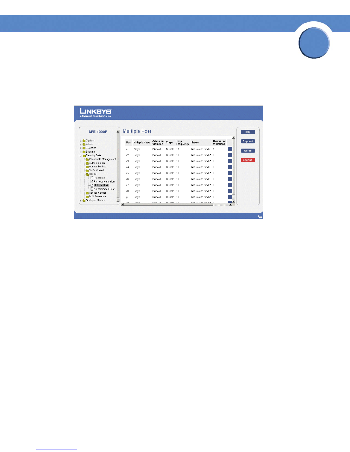
Chapter
SFE1000P Gigabit Ethernet Switch Reference Guide
Defining Multiple Hosts
The 802.1X Multiple Host Page allows network managers to configure advanced port-based
authentication settings for specific ports and VLANs.
802.1X Multiple Host Page
5
The 802.1X Multiple Host Page contains the following fields:
• Port — Displays the port number for which the Multiple Hosts configuration is displayed.
• Multiple Hosts — Indicates whether multiple hosts are enabled. Multiple hosts must be
enabled in order to either disable the ingress-filter, or to use port-lock security on the
selected port. The possible field values are:
– Single — Only the authorized host can access the port.
– Multiple — Multiple hosts can be attached to a single 802.1x-enabled port. Only one
host must be authorized for all hosts to access the network. If the host authentication
fails, or an EAPOL-logoff message is received, all attached clients are denied access to
the network.
• Action on Violation — Defines the action to be applied to packets arriving in single-host
mode, from a host whose MAC address is not the supplicant MAC address. The possible
field values are:
– Forward — Forwards the packet.
– Discard — Discards the packets. This is the default value.
– Shutdown — Discards the packets and shuts down the port. The ports remains shut
down until reactivated, or until the device is reset.
• Traps — Indicates if traps are enabled for Multiple Hosts. The possible field values are:
– Enable — Indicates that traps are enabled for Multiple hosts.
Chapter 5: Configuring Device Security
Defining 802.1x
50
Page 59
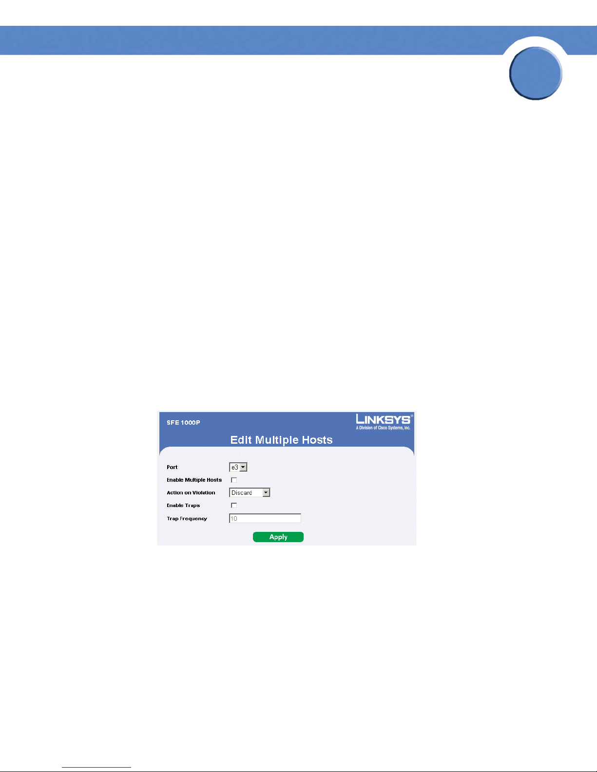
Chapter
SFE1000P Gigabit Ethernet Switch Reference Guide
– Disable — Indicates that traps are disabled for Multiple hosts.
• Trap Frequency — Defines the time period by which traps are sent to the host. The Trap
Frequency (1-1000000) field can be defined only if multiple hosts are disabled. The default
is 10 seconds.
• Status — Indicates the host status. If there is an asterisk (*), the port is either not linked or is
down. The possible field values are:
– Unauthorized — Indicates that either the port control is Force Unauthorized and the port
link is down, or the port control is Auto but a client has not been authenticated via the
port.
– Not in Auto Mode — Indicates that the port control is Forced Authorized, and clients
have full port access.
– Single-host Lock — Indicates that the port control is Auto and a single client has been
authenticated via the port.
– No Single Host — Indicates that Multiple Host is enabled.
5
• Number of Violations — Indicates the number of packets that arrived on the interface in
single-host mode, from a host whose MAC address is not the supplicant MAC address.
Modifying Multiple Host Settings
Edit Multiple Host Page
The Edit Multiple Host Page contains the following fields:
• Port — Displays the port number for which advanced port-based authentication is enabled.
• Enable Multiple Hosts — Indicates whether multiple hosts are enabled. Multiple hosts must
be enabled in order to either disable the ingress-filter, or to use port-lock security on the
selected port. The possible field values are:
– Checked — Multiple host mode is enabled.
– Unchecked — Single host mode is enabled. This is the default value.
Chapter 5: Configuring Device Security
Defining 802.1x
51
Page 60
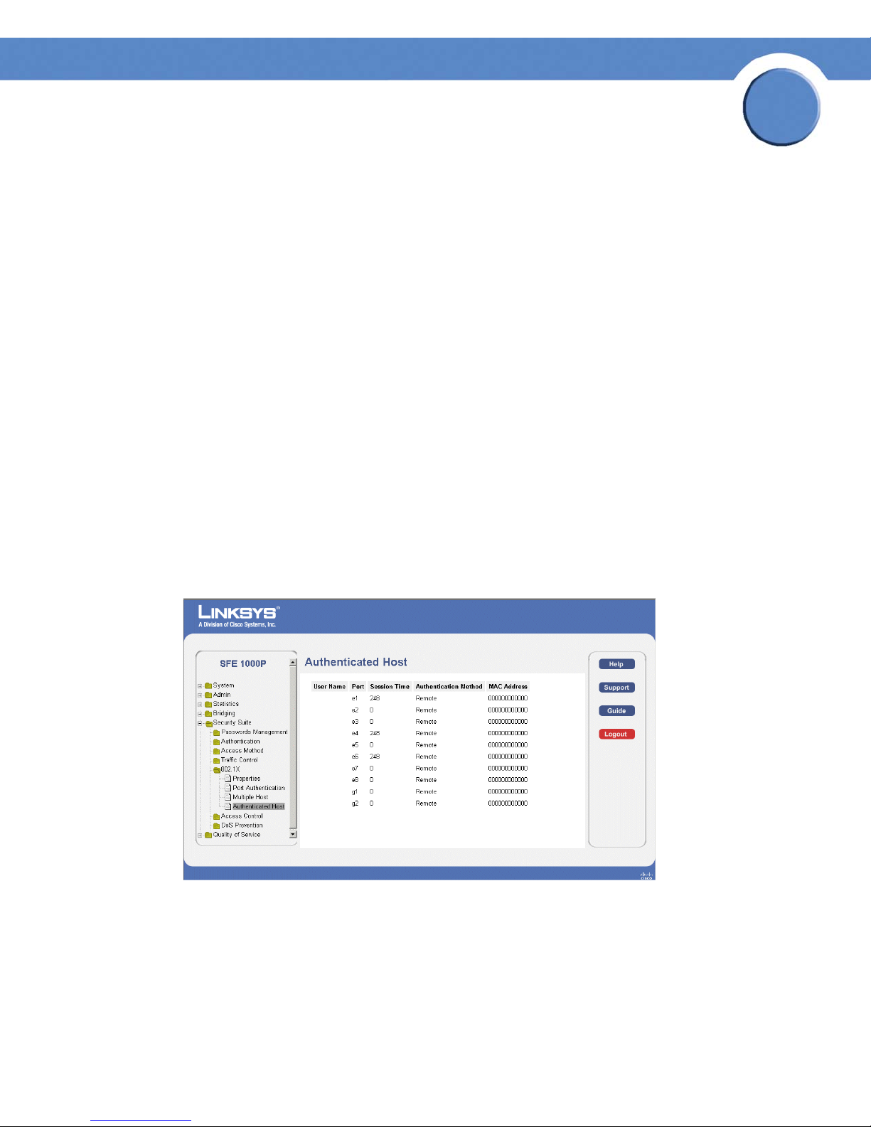
Chapter
SFE1000P Gigabit Ethernet Switch Reference Guide
• Action on Violation — Defines the action to be applied to packets arriving in single-host
mode, from a host whose MAC address is not the supplicant MAC address. The possible
field values are:
– Forward — Forwards the packet.
– Discard — Discards the packets. This is the default value.
– DiscardDisable — Discards the packets and shuts down the port. The ports remains shut
down until reactivated, or until the device is reset.
• Enable Traps — Indicates if traps are enabled for Multiple Hosts. The possible field values
are:
– Checked — Indicates that traps are enabled for Multiple hosts.
– Unchecked — Indicates that traps are disabled for Multiple hosts.
• Trap Frequency — Defines the time period by which traps are sent to the host. The Trap
Frequency (1-1000000) field can be defined only if multiple hosts are disabled. The default
is 10 seconds.
5
Defining Authenticated Host
The Authenticated Host Page contains a list of authenticated users.
Authenticated Host Page
The Authenticated Host Page contains the following fields:
• User Name — Lists the supplicants that were authenticated, and are permitted on each port.
• Port — Displays the port number.
• Session time — Displays the amount of time (in seconds) the supplicant was logged on the
port.
Chapter 5: Configuring Device Security
Defining 802.1x
52
Page 61

Chapter
SFE1000P Gigabit Ethernet Switch Reference Guide
• Authentication Method — Displays the method by which the last session was authenticated.
The possible field values are:
– Remote — 802.1x authentication is not used on this port (port is forced-authorized).
– None — The supplicant was not authenticated.
– RADIUS — The supplicant was authenticated by a RADIUS server.
• MAC Address — Displays the supplicant MAC address.
Defining Access Control
Access Control Lists (ACL) allow network managers to define classification actions and rules for
specific ingress ports. Your switch supports up to 256 ACLs. Packets entering an ingress port, with
an active ACL, are either admitted or denied entry. If they are denied entry, the user can disable the
port. ACLs are composed of access control entries (ACEs) that are made of the filters that determine
traffic classifications. The total number of ACEs that can be defined in all ACLs together is 256.
The Access Control section contains the following pages:
5
• Defining MAC Based ACL
• Defining IP Based ACL
• Defining ACL Binding
Defining MAC Based ACL
The MAC Based ACL Page page allows a MAC-based Access Control List (ACL) to be defined. The
table lists Access Control Elements (ACE) rules, which can be added only if the ACL is not bound to
an interface.
Chapter 5: Configuring Device Security
Defining Access Control
53
Page 62
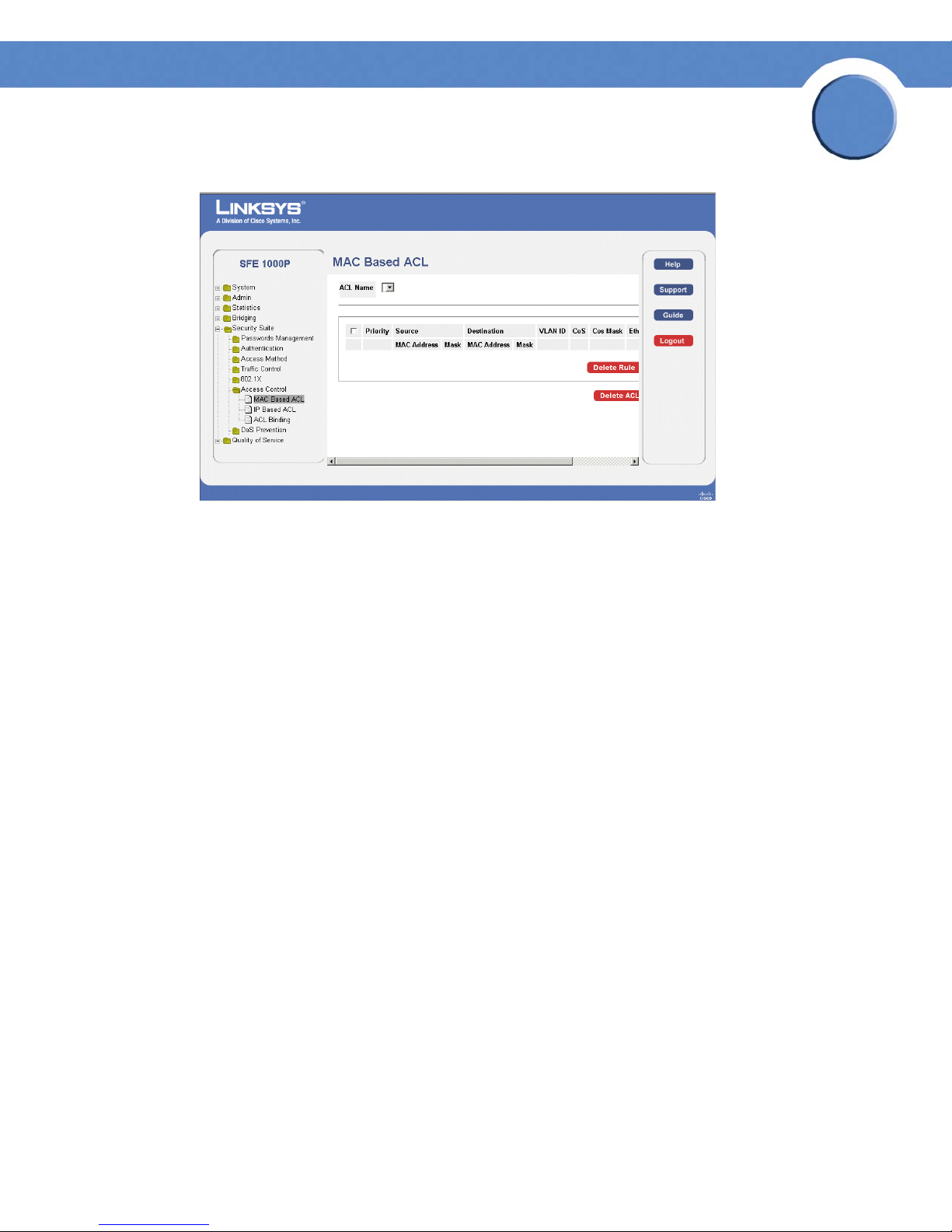
SFE1000P Gigabit Ethernet Switch Reference Guide
MAC Based ACL Page
Chapter
5
The MAC Based ACL Page contains the following fields:
• ACL Name — Displays the user-defined MAC based ACLs.
• Priority — Indicates the ACE priority, which determines which ACE is matched to a packet
on a first-match basis. The possible field values are 1-2147483647.
• Source MAC Address — Defines the source MAC address to match the ACE.
• Source MAC Mask — Defines the source MAC mask to match the ACE.
• Destination MAC Address — Defines the destination MAC address to match the ACE.
• Destination MAC Mask — Defines the destination MAC mask to the which packets are
matched.
• VLAN ID — Matches the packet’s VLAN ID to the ACE. The possible field values are 1 to
4093.
• CoS — Class of Service of the packet.
• CoS Mask — Wildcard bits to be applied to the CoS.
• Ether Type — The Ethernet type of the packet.
• Action — Indicates the ACL forwarding action. For example, the port can be shut down, a
trap can be sent to the network administrator, or packet is assigned rate limiting restrictions
for forwarding. Possible field values are:
– Permit — Forwards packets which meet the ACL criteria.
– Deny — Drops packets which meet the ACL criteria.
Chapter 5: Configuring Device Security
Defining Access Control
54
Page 63
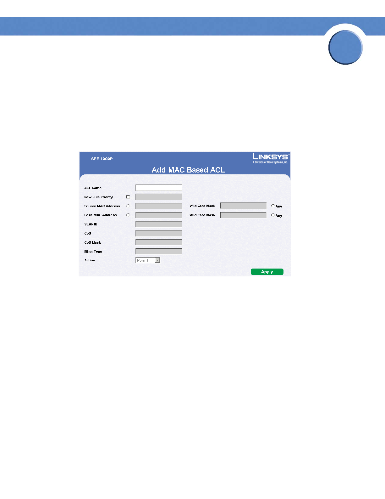
SFE1000P Gigabit Ethernet Switch Reference Guide
– Shutdown — Drops packet that meet the ACL criteria, and disables the port to which the
packet was addressed. Ports are reactivated from the Interface Configuration Page.
• Delete ACL — To remove an ACL, click the Delete ACL button.
• Delete Rule — To remove an ACE rule, click the rule’s checkbox and click the Delete Rule
button.
Adding an ACL
Add MAC Based ACL Page
Chapter
5
The Add MAC Based ACL Page contains the following fields:
• ACL Name — Displays the user-defined MAC based ACLs.
• New Rule Priority — Indicates the ACE priority, which determines which ACE is matched to
a packet on a first-match basis. The possible field values are 1-2147483647.
• Source Address
– MAC Address — Matches the source MAC address from which packets are addressed
to the ACE.
– Wild Card Mask — Indicates the source MAC Address wild card mask. Wildcards are
used to mask all or part of a source MAC Address. Wild card masks specify which
octets are used and which octets are ignored. A wild card mask of ff: ff:ff:ff:ff:ff
indicates that no octet is important. A wildcard of 00:00:00:00:00:00 indicates that all
the octets are important. For example, if the source MAC address 09:00:07:A9:B2:EB
and the wildcard mask is 00:ff:00:ff:00:ff, the 1st, 3rd, and 5th octets of the MAC
address are checked, while the 2nd, 4th, and 6th octets are ignored.
– Destination Address
Chapter 5: Configuring Device Security
Defining Access Control
55
Page 64

Chapter
SFE1000P Gigabit Ethernet Switch Reference Guide
– MAC Address — Matches the destination MAC address to which packets are addressed
to the ACE.
– Wild Card Mask — Indicates the destination MAC Address wild card mask. Wildcards
are used to mask all or part of a destination MAC Address. Wild card masks specify
which octets are used and which octets are ignored. A wild card mask of ff: ff:ff:ff:ff:ff
indicates that no octet is important. A wildcard of 00:00:00:00:00:00 indicates that all
the octets are important. For example, if the destination IP address 09:00:07:A9:B2:EB
and the wildcard mask is 00:ff:00:ff:00:ff, the 1st, 3rd, and 5th octets of the MAC
address are checked, while the 2nd, 4th, and 6th octets are ignored.
5
• VLAN ID —
• CoS — Class of Service of the packet.
• CoS Mask — Wildcard bits to be applied to the CoS.
• Ether Type — The Ethernet type of the packet.
• Action — Indicates the ACL forwarding action. For example, the port can be shut down, a
trap can be sent to the network administrator, or packet is assigned rate limiting restrictions
for forwarding. Possible field values are:
– Permit — Forwards packets which meet the ACL criteria.
– Deny — Drops packets which meet the ACL criteria.
– Shutdown — Drops packet that meet the ACL criteria, and disables the port to which the
packet was
Matches the packet’s VLAN ID to the ACE. The possible field values are 1 to 4093.
addressed. Ports are reactivated from the Interface Configuration Page.
Adding Rule to MAC Based ACL
Add MAC Based Rule Page
The Add MAC Based Rule Page contains the following fields:
Chapter 5: Configuring Device Security
Defining Access Control
56
Page 65

SFE1000P Gigabit Ethernet Switch Reference Guide
• ACL Name — Displays the user-defined MAC based ACLs.
Chapter
5
• New Rule Priority —
packet on a first-match basis. The possible field values are 1-2147483647.
• Source Address
– MAC Address — Matches the source MAC address from which packets are addressed
to the ACE.
– Wild Card Mask — Indicates the source MAC Address wild card mask. Wildcards are
used to mask all or part of a source MAC Address. Wild card masks specify which
octets are used and which octets are ignored. A wild card mask of ff: ff:ff:ff:ff:ff
indicates that no octet is important. A wildcard of 00:00:00:00:00:00 indicates that all
the octets are important. For example, if the source MAC address 09:00:07:A9:B2:EB
and the wildcard mask is 00:ff:00:ff:00:ff, the 1st, 3rd, and 5th octets of the MAC
address are checked, while the 2nd, 4th, and 6th octets are ignored.
• Destination Address
– MAC Address — Matches the destination MAC address to which packets are addressed
to the ACE.
– Wild Card Mask — Indicates the destination MAC Address wild card mask. Wildcards
are used to mask all or part of a destination MAC Address. Wild card masks specify
which octets are used and which octets are ignored. A wild card mask of ff: ff:ff:ff:ff:ff
indicates that no octet is important. A wildcard of 00:00:00:00:00:00 indicates that all
the octets are important. For example, if the destination IP address 09:00:07:A9:B2:EB
and the wildcard mask is 00:ff:00:ff:00:ff, the 1st, 3rd, and 5th octets of the MAC
address are checked, while the 2nd, 4th, and 6th octets are ignored.
Indicates the ACE priority, which determines which ACE is matched to a
• VLAN ID —
• CoS — Class of Service of the packet.
• CoS Mask — Wildcard bits to be applied to the CoS.
• Ether Type —
• Action — Indicates the ACL forwarding action. The possible field values are:
– Permit — Forwards packets which meet the ACL criteria.
– Deny — Drops packets which meet the ACL criteria.
– Shutdown — Drops packet that meet the ACL criteria, and disables the port to which the
packet was
Chapter 5: Configuring Device Security
Defining Access Control
Matches the packet’s VLAN ID to the ACE. The possible field values are 1 to 4093.
The Ethernet type of the packet.
addressed.
57
Page 66
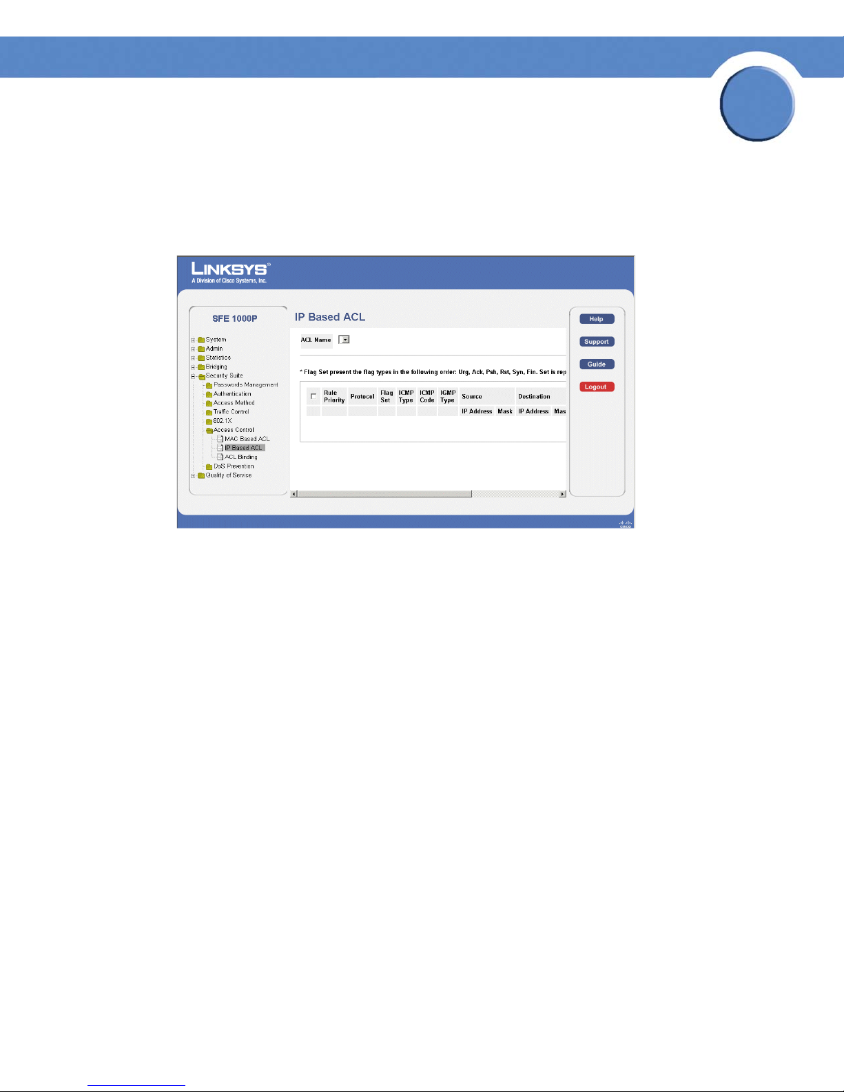
Chapter
SFE1000P Gigabit Ethernet Switch Reference Guide
Defining IP Based ACL
The IP Based ACL Page contains information for defining IP Based ACLs, including defining the
ACEs defined for IP Based ACLs.
IP Based ACL Page
5
The IP Based ACL Page contains the following fields:
• ACL Name — Displays the user-defined IP based ACLs.
• Rule Priority — Indicates the rule priority, which determines which rule is matched to a
packet on a first-match basis.
• Protocol — Creates an ACE based on a specific protocol. The available protocols are:
– ICMP — Internet Control Message Protocol (ICMP). The ICMP allows the gateway or
destination host to communicate with the source host. For example, to report a
processing error.
– IGMP — Internet Group Management Protocol (IGMP). Allows hosts to notify their local
switch or router that they want to receive transmissions assigned to a specific multicast
group.
– IP — Internet Protocol (IP). Specifies the format of packets and their addressing method.
IP addresses packets and forwards the packets to the correct port.
– TCP — Transmission Control Protocol (TCP). Enables two hosts to communicate and
exchange data streams. TCP guarantees packet delivery, and guarantees packets are
transmitted and received in the order the are sent.
– EGP — Exterior Gateway Protocol (EGP). Permits exchanging routing information
between two neighboring gateway hosts in an autonomous systems network.
Chapter 5: Configuring Device Security
Defining Access Control
58
Page 67

Chapter
SFE1000P Gigabit Ethernet Switch Reference Guide
– IGP — Interior Gateway Protocol (IGP). Allows for routing information exchange
between gateways in an autonomous network.
– UDP — User Datagram Protocol (UDP). Communication protocol that transmits packets
but does not guarantee their delivery.
– HMP — Host Mapping Protocol (HMP). Collects network information from various
networks hosts. HMP monitors hosts spread over the internet as well as hosts in a single
network.
– RDP — Remote Desktop Protocol (RDP). Allows a clients to communicate with the
Terminal Server over the network.
– IDPR — Matches the packet to the Inter-Domain Policy Routing (IDPR) protocol.
– IPV6 — Internet Routing Protocol version 6 (IPv6). Provides a newer version of the
Internet Protocol, and follows IP version 4 (IPv4). IPv6 increases the IP address size from
32 bits to 128 bits. In addition, IPv6 support more levels of addressing hierarchy, more
addressable nodes, and supports simpler auto-configuration of addresses.
5
– IPV6:ROUTE — Matches packets to the IPv6 Route through a Gateway (IPV6:ROUTE).
–IPV6:FRAG — Matches packets to the IPv6 Fragment Header (IPV6:FRAG).
– IDRP— Matches the packet to the Inter-Domain Routing Protocol (IDRP).
– RSVP — Matches the packet to the ReSerVation Protocol (RSVP).
– AH — Authentication Header (AH). Provides source host authentication and data
integrity.
– IPV6:ICMP — Matches packets to the Matches packets to the IPv6 and Internet Control
Message Protocol.
– EIGRP — Enhanced Interior Gateway Routing Protocol (EIGRP). Provides fast
convergence, support for variable-length subnet mask, and supports multiple network
layer protocols.
– OSPF — The Open Shortest Path First (OSPF) protocol is a link-state, hierarchical
interior gateway protocol (IGP) for network routing Layer Two (2) Tunneling Protocol, an
extension to the PPP protocol that enables ISPs to operate Virtual Private Networks
(VPNs).
– IPIP — IP over IP (IPIP). Encapsulates IP packets to create tunnels between two routers.
This ensure that IPIP tunnel appears as a single interface, rather than several separate
interfaces. IPIP enables tunnel intranets over the internet, and provides an alternative to
source routing.
– PIM — Matches the packet to Protocol Independent Multicast (PIM).
– L2TP
Chapter 5: Configuring Device Security
Defining Access Control
— Matches the packet to Layer 2 Internet Protocol (L2IP).
59
Page 68

Chapter
SFE1000P Gigabit Ethernet Switch Reference Guide
– ISIS — Intermediate System - Intermediate System (ISIS). Distributes IP routing
information throughout a single Autonomous System in IP networks.
– ANY — Matches the protocol to any protocol.
• Flag Set — Sets the indicated TCP flag that can be triggered.
• ICMP Type — Filters packets by ICMP message type. The field values are 0-255.
• ICMP Code — Indicates and ICMP message code for filtering ICMP packets. ICMP packets
that are filtered by ICMP message type can also be filtered by the ICMP message code.
• IGMP Type — Filters packets by IGMP message or message types.
• Source Address
– IP Address — Matches the source port IP address from which packets are addressed to
the ACE.
– Mask — Defines the source IP address wildcard mask. Wildcard masks specify which
bits are used and which bits are ignored. A wild card mask of 255.255.255.255
indicates that no bit is important. A wildcard of 0.0.0.0 indicates that all the bits are
important. For example, if the source IP address 149.36.184.198 and the wildcard
mask is 255.36.184.00, the first eight bits of the IP address are ignored, while the last
eight bits are used.
5
• Destination Address
– IP Address — Matches the destination port IP address to which packets are addressed to
the ACE.
– Mask — Defines the destination IP address wildcard mask.
• DSCP — Matches the packets DSCP value.
• IP Perch. — Matches the packet IP Precedence value to the ACE. Either the DSCP value or
the IP Precedence value is used to match packets to ACLs. The possible field range is 0-7.
• Action — Indicates the action assigned to the packet matching the ACL. Packets are
forwarded or dropped. In addition, the port can be shut down, a trap can be sent to the
network administrator, or packet is assigned rate limiting restrictions for forwarding. The
options are as follows:
– Permit — Forwards packets which meet the ACL criteria.
– Deny — Drops packets which meet the ACL criteria.
– Shutdown — Drops packet that meets the ACL criteria, and disables the port to which
the packet was addressed. Ports are reactivated from the Port Management page.
• Delete ACL — To remove an ACL, click the Delete ACL button.
Chapter 5: Configuring Device Security
Defining Access Control
60
Page 69

SFE1000P Gigabit Ethernet Switch Reference Guide
• Delete Rule — To remove an ACE rule, click the rule’s checkbox and click the Delete Rule
button.
Add IP Based ACL
Add IP Based ACL Page
Chapter
5
The Add IP Based ACL Page contains the following fields:
• ACL Name — Displays the user-defined IP based ACLs.
• New Rule Priority — Indicates the rule priority, which determines which rule is matched to a
packet on a first-match basis.
• Protocol — Creates an ACE based on a specific protocol. For a list of available protocols,
see the Protocol field description in the IP Based ACL Page above.
• Source Port — Defines the TCP/UDP source port to which the ACE is matched. This field is
active only if 800/6-TCP or 800/17-UDP are selected in the Select from List drop-down
menu. The possible field range is 0 - 65535.
• Destination Port — Defines the TCP/UDP destination port. This field is active only if 800/6-
TCP or 800/17-UDP are selected in the Select from List drop-down menu. The possible field
range is 0 - 65535.
• TCP Flags — Filters packets by TCP flag. Filtered packets are either forwarded or dropped.
Filtering packets by TCP flags increases packet control, which increases network security.
• ICMP — Indicates if ICMP packets are permitted on the network.
Chapter 5: Configuring Device Security
Defining Access Control
61
Page 70

Chapter
SFE1000P Gigabit Ethernet Switch Reference Guide
• ICMP Code — Indicates and ICMP message code for filtering ICMP packets. ICMP packets
that are filtered by ICMP message type can also be filtered by the ICMP message code.
• IGMP — Filters packets by IGMP message or message types.
• Source Address
– IP Address — Matches the source port IP address from which packets are addressed to
the ACE.
– Mask — Defines the source IP address wildcard mask. Wildcard masks specify which
bits are used and which bits are ignored. A wild card mask of 255.255.255.255
indicates that no bit is important. A wildcard of 0.0.0.0 indicates that all the bits are
important. For example, if the source IP address 149.36.184.198 and the wildcard
mask is 255.36.184.00, the first eight bits of the IP address are ignored, while the last
eight bits are used.
• Best. Address
– IP Address — Matches the destination port IP address to which packets are addressed to
the ACE.
5
– Mask — Defines the destination IP address wildcard mask.
Select either Match DSCP or Match IP.
• Match DSCP — Matches the packet to the DSCP tag value.
• Match IP Precedence — Matches the packet IP Precedence value to the ACE. Either the
DSCP value or the IP Precedence value is used to match packets to ACLs. The possible field
range is 0-7.
• Action — Indicates the action assigned to the packet matching the ACL. Packets are
forwarded or dropped. In addition, the port can be shut down, a trap can be sent to the
network administrator, or packet is assigned rate limiting restrictions for forwarding. The
options are as follows:
– Permit — Forwards packets which meet the ACL criteria.
– Deny — Drops packets which meet the ACL criteria.
– Shutdown — Drops packet that meets the ACL criteria, and disables the port to which
the packet was addressed. Ports are reactivated from the Port Management page.
Chapter 5: Configuring Device Security
Defining Access Control
62
Page 71

Adding an IP Based Rule
SFE1000P Gigabit Ethernet Switch Reference Guide
Add IP Based Rule Page
Chapter
5
The Add IP Based Rule Page contains the following fields:
• ACL Name — Displays the user-defined IP based ACLs.
• New Rule Priority — Indicates the rule priority, which determines which rule is matched to a
packet on a first-match basis.
• Protocol — Creates an ACE based on a specific protocol. For a list of available protocols,
see the Protocol field description in the IP Based ACL Page above.
• Source Port — Defines the TCP/UDP source port to which the ACE is matched. This field is
active only if 800/6-TCP or 800/17-UDP are selected in the Select from List drop-down
menu. The possible field range is 0 - 65535.
• Destination Port — Defines the TCP/UDP destination port. This field is active only if 800/6-
TCP or 800/17-UDP are selected in the Select from List drop-down menu. The possible field
range is 0 - 65535.
• TCP Flags — Filters packets by TCP flag. Filtered packets are either forwarded or dropped.
Filtering packets by TCP flags increases packet control, which increases network security.
The possible field values are:
• ICMP — Indicates if ICMP packets are permitted on the network.
Chapter 5: Configuring Device Security
Defining Access Control
63
Page 72

Chapter
SFE1000P Gigabit Ethernet Switch Reference Guide
• ICMP Code — Indicates and ICMP message code for filtering ICMP packets. ICMP packets
that are filtered by ICMP message type can also be filtered by the ICMP message code.
• IGMP — Filters packets by IGMP message or message types.
• Source IP Address — Matches the source port IP address to which packets are addressed to
the ACE.
• Best. IP Address — Matches the destination port IP address to which packets are addressed
to the ACE.
Match DSCP or Match IP.
• Match DSCP — Matches the packet to the DSCP tag value.
• Match IP Precedence — Matches the packet IP Precedence value to the ACE. Either the
DSCP value or the IP Precedence value is used to match packets to ACLs. The possible field
range is 0-7.
• Action — Indicates the action assigned to the packet matching the ACL. Packets are
forwarded or dropped. In addition, the port can be shut down, a trap can be sent to the
network administrator, or packet is assigned rate limiting restrictions for forwarding. The
options are as follows:
5
– Permit — Forwards packets which meet the ACL criteria.
– Deny — Drops packets which meet the ACL criteria.
– Shutdown — Drops packet that meets the ACL criteria, and disables the port to which
the packet was addressed. Ports are reactivated from the Port Management page.
Chapter 5: Configuring Device Security
Defining Access Control
64
Page 73

Chapter
SFE1000P Gigabit Ethernet Switch Reference Guide
Defining ACL Binding
When an ACL is bound to an interface, all the ACE rules that have been defined are applied to the
selected interface.
that do not match the ACL are matched to the default rule, which is Drop unmatched packets.
Whenever an ACL is assigned on a port or a LAG flows from that ingress interface
ACL Binding Page
5
The ACL Binding Page contains the following fields:
• Copy From Entry Number — Copies the ACL information from the defined interface.
• To Entry Number(s) — Assigns the copied ACL information to the defined interface.
• Ports/LAGs — Indicates the interface to which the ACL is bound.
For each entry, an interface has a bound ACL.
• Interface — Indicates the interface to which the associated ACL is bound.
• ACL Name — Indicates the ACL which is bound to the associated interface.
Chapter 5: Configuring Device Security
Defining Access Control
65
Page 74
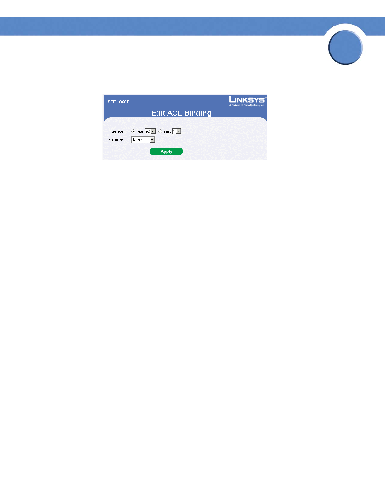
SFE1000P Gigabit Ethernet Switch Reference Guide
Modifying ACL Binding
Edit ACL Binding Page
The Edit ACL Binding Page contains the following fields:
• Interface — Indicates the interface to which the ACL is bound.
• Select ACL — Indicates the ACL which is bound to the interface.
Chapter
5
Chapter 5: Configuring Device Security
Defining Access Control
66
Page 75
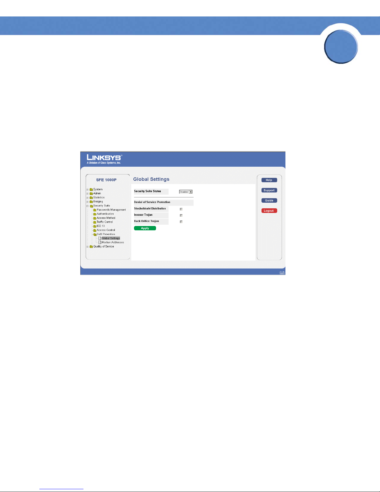
SFE1000P Gigabit Ethernet Switch Reference Guide
Defining DoS Prevention
The DoS Prevention section contains the following pages:
• Global Settings
• Defining Martian Addresses
Global Settings
Global Settings Page
Chapter
5
The Global Settings Page contains the following fields:
• Security Suite Status — Indicates if DOS security is enabled on the device. The possible field
values are:
– Enable — Enables DOS security.
– Disable — Disables DOS security on the device. This is the default value.
• Denial of Service Protection — Indicates if any of the services listed below are enabled. If
the service protection is disabled, the Stacheldraht Distribution, Invasor Trojan, and Back
Office Trojan fields are disabled.
– Stacheldraht Distribution — Discards TCP packets with source TCP port equal to 16660.
– Invasor Trojan — Discards TCP packets with destination TCP port equal to 2140 and
source TCP port equal to 1024.
– Back Orifice Trojan — Discards UDP packets with destination UDP port equal to 31337
and source UDP port equal to 1024.
Chapter 5: Configuring Device Security
Defining DoS Prevention
67
Page 76

Defining Martian Addresses
SFE1000P Gigabit Ethernet Switch Reference Guide
Martian Addresses Page
Chapter
5
The Martian Addresses Page contains the following fields:
• IP Address — Displays the IP addresses for which DoS attack is enabled.
• Mask — Displays the Mask for which DoS attack is enabled.
• Delete — To remove a Martian address, click the entry’s checkbox and click the Delete
button.
Chapter 5: Configuring Device Security
Defining DoS Prevention
68
Page 77
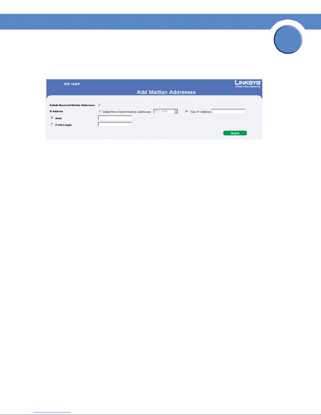
SFE1000P Gigabit Ethernet Switch Reference Guide
Add Martian Address Page
Add Martian Addresses Page
The Add Martian Addresses Page contains the following fields:
• Include Reserved Martian Addresses — Indicates that packets arriving from Martian
addresses are dropped.
Chapter
5
The possible values are:
– Checked — Includes specially reserved IP addresses in the Martian Address list. When
enabled, the following IP addresses are included:
0.0.0.0/8 (except 0.0.0.0/32), 127.0.0.0/8
192.0.2.0/24, 224.0.0.0/4
240.0.0.0/4 (except 255.255.255.255/32)
– Unchecked — Does not include specially reserved IP addresses in the Martian Address
list.
• IP Address — Enter the Martian IP addresses for which DoS attack is enabled. The possible
values are:
– One of the addresses in the known Martian IP address list. If the Include Reserved
Martian Addresses option is checked, this list includes reserved Martian Addresses.
– New IP Address — Enter an IP Address that is not on the list.
• Mask — Enter the Mask for which DoS attack is enabled.
• Prefix Length — Defines the IP route prefix for the destination IP.
Chapter 5: Configuring Device Security
Defining DoS Prevention
69
Page 78
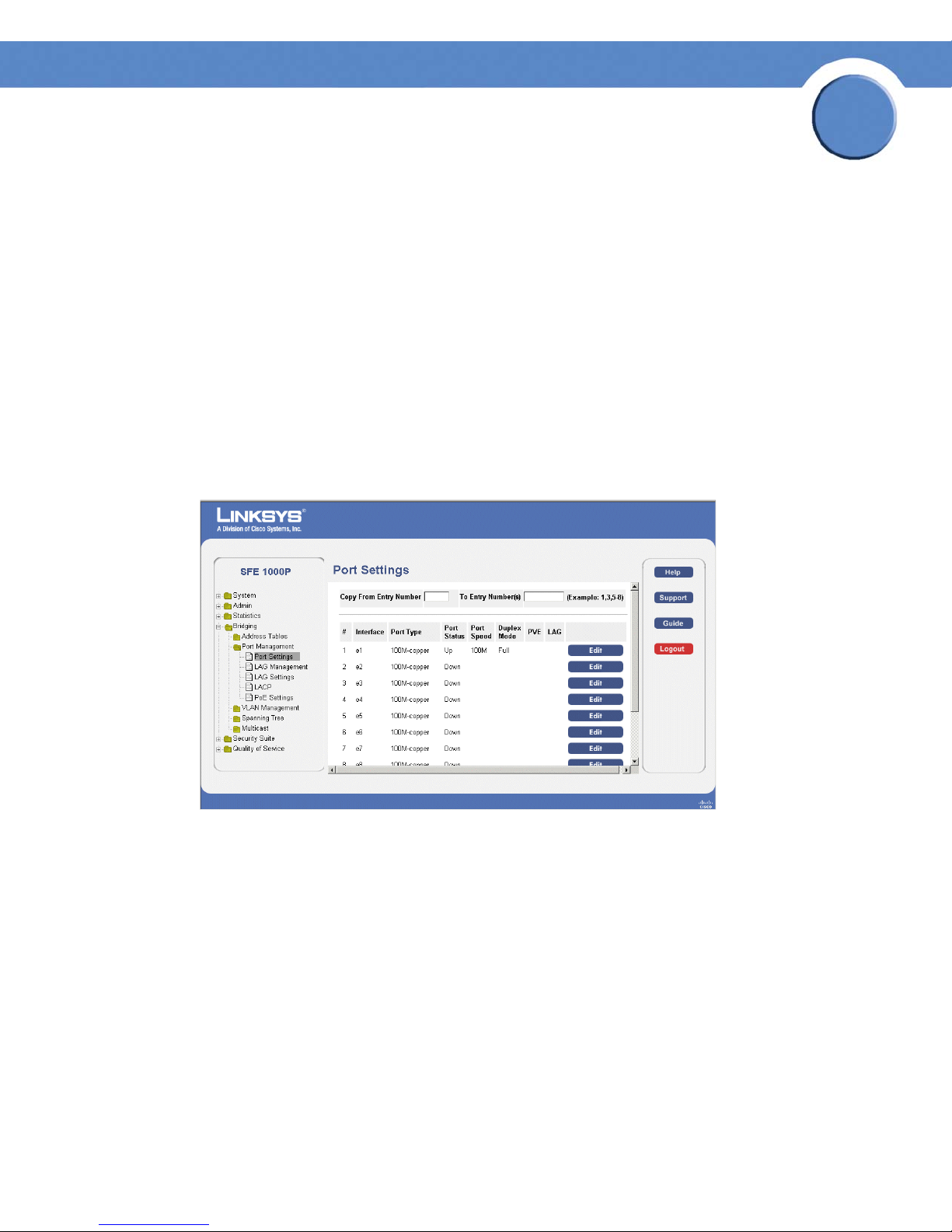
SFE1000P Gigabit Ethernet Switch Administration Guide
Configuring Device Interfaces
This section contains information for configuring ports and contains the following topic:
• Defining Port Settings
• Defining LAG Management
• Defining LAG Settings
•Configuring LACP
Defining Port Settings
The Port Settings Page contains fields for defining port parameters.
Port Settings Page
Chapter
6
The Port Settings Page contains the following fields:
• Copy from Entry Number — Copies the port settings from the specified port.
• to Entry Number(s) — Assigns the copied port information to a specified port.
• Interface — Displays the port number.
• Port Type — Displays the port type. The possible field values are:
– 100M-Copper/1000M-Copper/ComboF/ComboC
port connection.
– Fiber — Indicates the port has a fiber optic port connection.
• Port Status — Displays the port connection status. The possible field values are:
Chapter 6: Configuring Device Interfaces
Defining Port Settings
— Indicates the port has a copper
70
Page 79

Chapter
SFE1000P Gigabit Ethernet Switch Administration Guide
– Up — Port is connected.
– Down — Port is disconnected.
• Port Speed — Displays the current port speed.
• Duplex Mode — Displays the port duplex mode. This field is configurable only when auto
negotiation is disabled, and the port speed is set to 10M or 100M. This field cannot be
configured on LAGs. The possible field values are:
– Full — Indicates that the interface supports transmission between the device and the
client in both directions simultaneously.
– Half — Indicates that the interface supports transmission between the device and the
client in only one direction at a time.
• PVE — Indicates that this port is protected by an uplink, so that the forwarding decisions are
overwritten by those of the port that protects it.
• LAG — Defines if the port is part of a Link Aggregation (LAG).
6
Chapter 6: Configuring Device Interfaces
Defining Port Settings
71
Page 80

Modifying Port Settings
SFE1000P Gigabit Ethernet Switch Administration Guide
Edit Port Settings Page
Chapter
6
The Edit Port Settings Page contains the following fields:
• Port — Displays the port number.
• Description — The port’s user-defined name.
• Port Type — Displays the port type. The possible field values are:
– 100M-Copper/1000M-Copper/ComboF/ComboC — Indicates the port has a copper
port connection.
– Fiber — Indicates the port has a fiber optic port connection.
• Admin Status — Enables or disables traffic forwarding through the port.
• Current Port Status — Displays the port connection status.
• Reactivate Suspended Port — Reactivates a port if the port has been disabled through the
locked port security option.
• Operational Status — Indicates whether the port is currently active or inactive.
Chapter 6: Configuring Device Interfaces
Defining Port Settings
72
Page 81

Chapter
SFE1000P Gigabit Ethernet Switch Administration Guide
• Admin Speed — The configured rate for the port. The port type determines what speed
setting options are available. You can designate admin speed only when the port autonegotiation
• Current Port Speed — Displays the current port speed.
• Admin Duplex — Defines the port duplex mode. This field is configurable only when auto
negotiation is disabled, and the port speed is set to 10M or 100M. This field cannot be
configured on LAGs. The possible field values are:
– Full — Indicates that the interface supports transmission between the device and the
client in both directions simultaneously.
– Half — Indicates that the interface supports transmission between the device and the
client in only one direction at a time.
• Current Duplex Mode — Displays the port current duplex mode.
• Auto Negotiation — Enables Auto Negotiation on the port. Auto Negotiation is a protocol
between two link partners that enables a port to advertise its transmission rate, duplex mode
and flow control abilities to its partner.
is disabled.
6
• Current Auto Negotiation — Displays the Auto Negotiation status on the port.
• Admin Advertisement — Specifies the capabilities to be advertised by the Port. The possible
field values are:
– Max Capability — Indicates that all port speeds and Duplex mode settings can be
accepted.
– 10 Half — Indicates that the port is advertising a 10 mbps speed and half Duplex mode
setting.
– 10 Full — Indicates that the port is advertising a 10 mbps speed and full Duplex mode
setting.
– 100 Half — Indicates that the port is advertising a 100 mbps speed and half Duplex
mode setting.
– 100 Full — Indicates that the port is advertising a 100 mbps speed and full Duplex
mode setting.
• 1000 Full — Indicates that the port is advertising a 1000 mbps speed and full Duplex mode
setting.
• Current Advertisement — The port advertises its capabilities to its neighbor port to start the
negotiation process. The possible field values are those specified in the Admin
Advertisement field.
• Neighbor Advertisement — The neighbor port (the port to which the selected interface is
connected) advertises its capabilities to the port to start the negotiation process. The possible
values are those specified in the Admin Advertisement field.
Chapter 6: Configuring Device Interfaces
Defining Port Settings
73
Page 82

Chapter
SFE1000P Gigabit Ethernet Switch Administration Guide
• Back Pressure — Enables Back Pressure mode on the port. Back Pressure mode is used with
Half Duplex mode to disable ports from receiving messages. The Back Pressure mode is
configured for ports currently in the Half Duplex mode.
• Current Back Pressure — Displays the Back Pressure mode on the port.
• Flow Control — Enables or disables flow control or enables the auto negotiation of flow
control on the port.
• Current Flow Control — Displays the current Flow Control setting.
• MDI/MDIX — Displays the Media Dependent Interface (MDI)/Media Dependent Interface
with Crossover (MDIX) status on the port. Hubs and switches are deliberately wired opposite
the way end stations are wired, so that when a hub or switch is connected to an end station,
a straight through Ethernet cable can be used, and the pairs are matched up properly.
When two hubs or switches are connected to each other, or two end stations are connected
to each other, a crossover cable is used to ensure that the correct pairs are connected. The
possible field values are:
– MDIX — Use for hubs and switches.
6
– Auto — Use to automatically detect the cable type.
– MDI — Use for end stations.
• Current MDI/MDIX — Displays the current MDI/MDIX setting.
• LAG — Defines if the port is part of a Link Aggregation (LAG).
• PVE — Indicates that this port is protected by an uplink, so that the forwarding decisions are
overwritten by those of the port that protects it.
Chapter 6: Configuring Device Interfaces
Defining Port Settings
74
Page 83

Chapter
SFE1000P Gigabit Ethernet Switch Administration Guide
Defining LAG Management
Link Aggregation optimizes port usage by linking a group of ports together to form a single LAG.
Aggregating ports multiplies the bandwidth between the devices, increases port flexibility, and
provides link redundancy.
The device supports both static LAGs and Link Aggregation Control Protocol (LACP) LAGs. LACP
LAGs negotiate aggregating port links with other LACP ports located on a different device. If the
other device ports are also LACP ports, the devices establish a LAG between them. Ensure the
following:
• All ports within a LAG must be the same media type.
• A VLAN is not configured on the port.
• The port is not assigned to a different LAG.
• Auto-negotiation mode is not configured on the port.
• The port is in full-duplex mode.
6
• All ports in the LAG have the same ingress filtering and tagged modes.
• All ports in the LAG have the same back pressure and flow control modes.
• All ports in the LAG have the same priority.
• All ports in the LAG have the same transceiver type.
• The device supports up to 8 LAGs, and eight ports in each LAG.
• Ports can be configured as LACP ports only if the ports are not part of a previously
configured LAG.
Ports added to a LAG lose their individual port configuration. When ports are removed from the
LAG, the original port configuration is applied to the ports.
Chapter 6: Configuring Device Interfaces
Defining LAG Management
75
Page 84

SFE1000P Gigabit Ethernet Switch Administration Guide
LAG Management Page
The LAG Management Page contains the following fields.
Chapter
6
• LAG — Displays the LAG number.
• Name — Displays the LAG name.
• Link State — Displays the link operational status.
• Member — Displays the ports configured to the LAG.
Chapter 6: Configuring Device Interfaces
Defining LAG Management
76
Page 85

Modifying LAG Membership
SFE1000P Gigabit Ethernet Switch Administration Guide
Edit LAG Membership Page
Chapter
6
The Edit LAG Membership Page contains the following fields.
• LAG — Displays the LAG number.
• LAG Name — Displays the LAG name.
• LACP — Indicates that LACP is enable on the LAG.
Chapter 6: Configuring Device Interfaces
Defining LAG Management
77
Page 86

Chapter
SFE1000P Gigabit Ethernet Switch Administration Guide
Defining LAG Settings
Link Aggregated Groups optimize port usage by linking a group of ports together to form a single
aggregated group. Link aggregated groups multiply the bandwidth between the devices, increase
port flexibility, and provide link redundancy.
The LAG Settings Page contains fields for configuring parameters for configured LAGs. The device
supports up to eight ports per LAG, and eight LAGs per system.
LAG Settings Page
6
The LAG Settings Page contains the following fields:
• Copy from Entry Number — Copies the LAG settings from the specified port.
• To Entry Number(s) — Assigns the copied LAG settings to the specified ports.
• LAG — Displays the LAG ID number.
• Description — Displays the user-defined port name.
• Type — The port types that comprise the LAG.
• Status — Indicates if the LAG is currently operating.
• Speed — The configured speed at which the LAG is operating.
• Auto Negotiation — The current Auto Negotiation setting. Auto Negotiation is a protocol
between two link partners that enables a port to advertise its transmission rate, duplex mode
and flow control abilities to its partner.
Chapter 6: Configuring Device Interfaces
Defining LAG Settings
78
Page 87

Chapter
SFE1000P Gigabit Ethernet Switch Administration Guide
• Flow Control — The current Flow Control setting. Flow control may be enabled, disabled, or
be in auto negotiation mode. Flow control operates when the ports are in full duplex mode.
• PVE — Indicates that this LAG’s ports are protected by an uplink, so that the forwarding
decisions are overwritten by those of the ports that protect them.
LAG Configuration Settings
LAG Configuration Settings
6
The LAG Configuration Settings contains the following fields:
• LAG — Displays the LAG ID number.
• Description — Displays the user-defined port name.
• LAG Type — The port types that comprise the LAG.
• Admin Status — Enables or disables traffic forwarding through the selected LAG.
• Current LAG Status — Indicates if the LAG is currently operating.
• Reactivate Suspended LAG — Reactivates a port if the LAG has been disabled through the
locked port security option.
• Operational Status — Defines whether the LAG is currently operational or non-operational.
• Admin Auto Negotiation — Enables or disables Auto Negotiation on the LAG. Autonegotiation is a protocol between two link partners that enables a LAG to advertise its
Chapter 6: Configuring Device Interfaces
Defining LAG Settings
79
Page 88

Chapter
SFE1000P Gigabit Ethernet Switch Administration Guide
transmission rate, duplex mode and flow control (the flow control default is disabled)
abilities to its partner.
• Current Auto Negotiation — The current Auto Negotiation setting.
• Admin Advertisement — Specifies the capabilities to be advertised by the LAG. The
possible field values are:
– Max Capability — Indicates that all LAG speeds and Duplex mode settings can be
accepted.
– 10 Half — Indicates that the LAG is advertising a 10 Mbps speed and half Duplex mode
setting.
– 10 Full — Indicates that the LAG is advertising a 10 Mbps speed and full Duplex mode
setting.
– 100 Half — Indicates that the LAG is advertising a 100 Mbps speed and half Duplex
mode setting.
6
– 100 Full — Indicates that the LAG is advertising a 100 Mbps speed and full Duplex
mode setting.
– 1000 Full — Indicates that the LAG is advertising a 1000 Mbps speed and full Duplex
mode setting.
• Current Advertisement — The LAG advertises its capabilities to its neighbor LAG to start the
negotiation process. The possible field values are those specified in the Admin
Advertisement field.
• Neighbor Advertisement — The neighbor LAG (the LAG to which the selected interface is
connected) advertises its capabilities to the LAG to start the negotiation process. The possible
values are those specified in the Admin Advertisement field.
• Admin Speed — The configured speed at which the LAG is operating.
• Current LAG Speed — The current speed at which the LAG is operating.
• Admin Flow Control — Enables or disables flow control or enables the auto negotiation of
flow control on the LAG.
• Current Flow Control — The user-designated Flow Control setting.
• PVE — Indicates if this LAG’s ports are protected by an uplink, so that the forwarding
decisions are overwritten by those of the ports that protect them.
Chapter 6: Configuring Device Interfaces
Defining LAG Settings
80
Page 89

Chapter
SFE1000P Gigabit Ethernet Switch Administration Guide
Configuring LACP
Aggregate ports can be linked into link-aggregation port-groups. Each group is comprised of ports
with the same speed, set to full-duplex operations.
Aggregated Links can be manually setup or automatically established by enabling Link Aggregation
Control Protocol (LACP) on the relevant links. Aggregate ports can be linked into link-aggregation
port-groups. Each group is comprised of ports with the same speed.
LACP Page
6
The LACP Page contains fields for configuring LACP LAGs.
• LACP System Priority — Indicates the global LACP priority value. The possible range is 1-
65535. The default value is 1.
• Port — Defines the port number to which timeout and priority values are assigned.
• Port Priority — Defines the LACP priority value for the port. The field range is 1-65535.
• LACP Timeout — Administrative LACP timeout. The possible field values are:
– Short — Defines a short timeout value.
– Long — Defines a long timeout value. This is the default value.
Chapter 6: Configuring Device Interfaces
Configuring LACP
81
Page 90
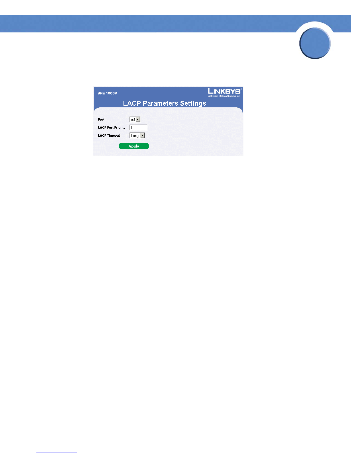
SFE1000P Gigabit Ethernet Switch Administration Guide
Modify LACP Parameter Settings
Edit LACP Page
The Edit LACP Page contains the following fields:
• Port — Defines the port number to which timeout and priority values are assigned.
• LACP Port Priority — Defines the LACP priority value for the port. The field range is 1-
65535.
Chapter
6
• LACP Timeout — Administrative LACP timeout. The possible field values are:
– Short — Defines a short timeout value.
– Long — Defines a long timeout value. This is the default value.
Chapter 6: Configuring Device Interfaces
Configuring LACP
82
Page 91

Chapter
SFE1000P Gigabit Ethernet Switch Administration Guide
Configuring VLANs
VLANs are logical subgroups with a Local Area Network (LAN) which combine user stations and
network devices into a single unit, regardless of the physical LAN segment to which they are
attached. VLANs allow network traffic to flow more efficiently within subgroups. VLANs use
software to reduce the amount of time it takes for network changes, additions, and moves to be
implemented.
VLANs have no minimum number of ports, and can be created per unit, per device, or through any
other logical connection combination, since they are software-based and not defined by physical
attributes.
VLANs function at Layer 2. Since VLANs isolate traffic within the VLAN, a Layer 3 router working at
a protocol level is required to allow traffic flow between VLANs. Layer 3 routers identify segments
and coordinate with VLANs. VLANs are Broadcast and Multicast domains. Broadcast and Multicast
traffic is transmitted only in the VLAN in which the traffic is generated.
VLAN tagging provides a method of transferring VLAN information between VLAN groups. VLAN
tagging attaches a 4-byte tag to packet headers. The VLAN tag indicates to which VLAN the packets
belong. VLAN tags are attached to the VLAN by either the end station or the network device. VLAN
tags also contain VLAN network priority information.
7
Combining VLANs and GARP (Generic Attribute Registration Protocol) allows network managers to
define network nodes into Broadcast domains. The VLAN Management section contains the
following pages:
• Defining VLAN Properties
• Defining VLAN Membership
• Defining Interface Settings
• Configuring GVRP Settings
Chapter 7: Configuring VLANs
83
Page 92

Chapter
SFE1000P Gigabit Ethernet Switch Administration Guide
Defining VLAN Properties
The VLAN Properties Page provides information and global parameters for configuring and working
with VLANs.
Properties Page
7
The Properties Page contains the following fields:
• VLAN ID — Displays the VLAN ID.
• VLAN Name — Displays the user-defined VLAN name.
• Type — Displays the VLAN type. The possible field values are:
– Dynamic — Indicates the VLAN was dynamically created through GARP.
– Static — Indicates the VLAN is user-defined.
– Default — Indicates the VLAN is the default VLAN.
• Authentication — Indicates whether unauthorized users can access a Guest VLAN. The
possible field values are:
– Enable — Enables unauthorized users to use the Guest VLAN.
– Disable — Disables unauthorized users from using the Guest VLAN.
Chapter 7: Configuring VLANs
Defining VLAN Properties
84
Page 93
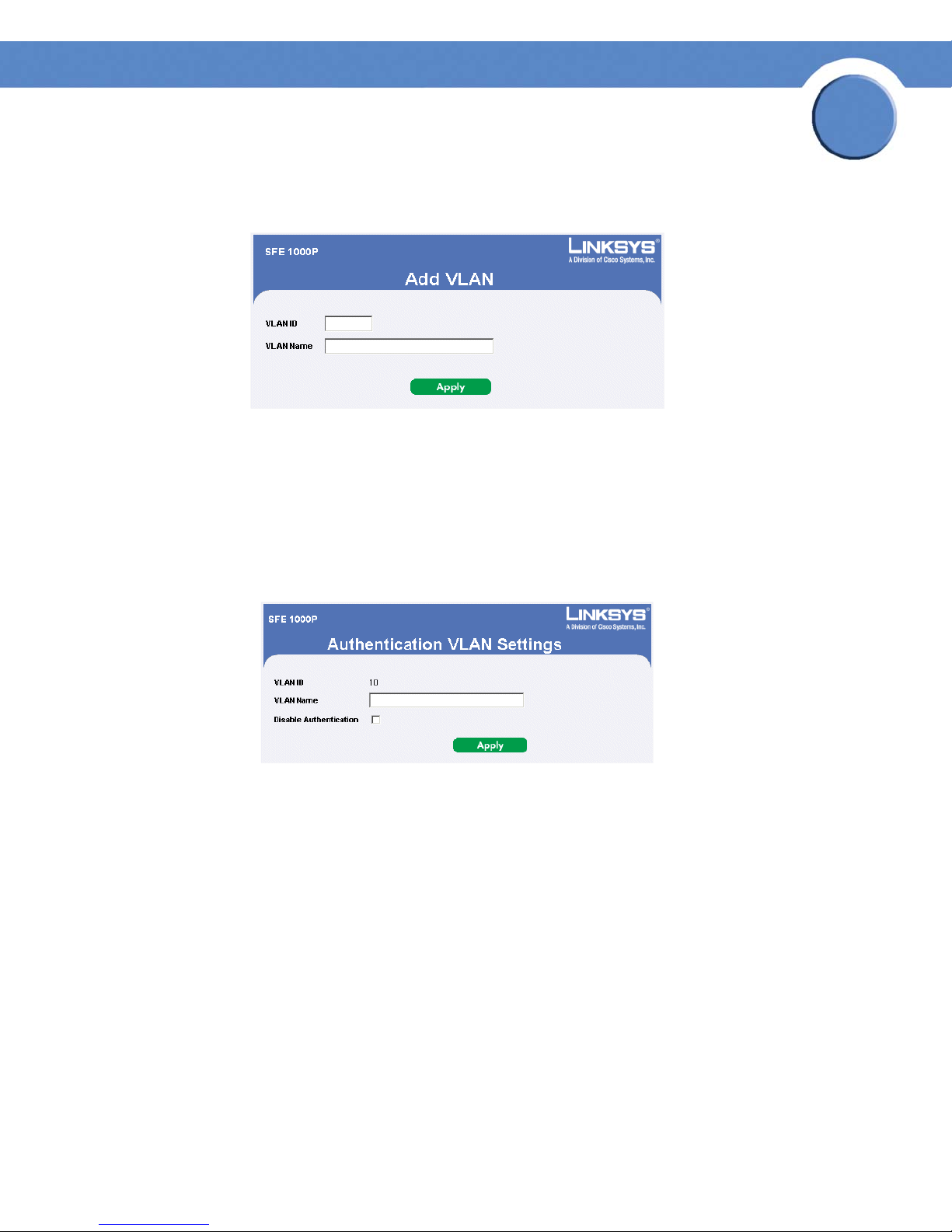
Chapter
SFE1000P Gigabit Ethernet Switch Administration Guide
Add VLAN
Add VLAN Page
The Add VLAN Page allows network administrators to define and configure new VLANs, contains
the following fields:
• VLAN ID — Indicates the VLAN ID.
• VLAN Name — Indicates the user-defined VLAN name.
7
Modifying VLANs
Edit VLAN Page
The Edit VLAN Page contains information for enabling VLAN guest authentication, and includes the
following fields:
• VLAN ID — Displays the VLAN ID.
• VLAN Name — Displays the VLAN name.
• Disable Authentication — Indicates whether unauthorized users can access a Guest VLAN.
The possible field values are:
– Enable — Enables unauthorized users to use the Guest VLAN.
– Disable — Disables unauthorized users from using the Guest VLAN.
Chapter 7: Configuring VLANs
Defining VLAN Properties
85
Page 94
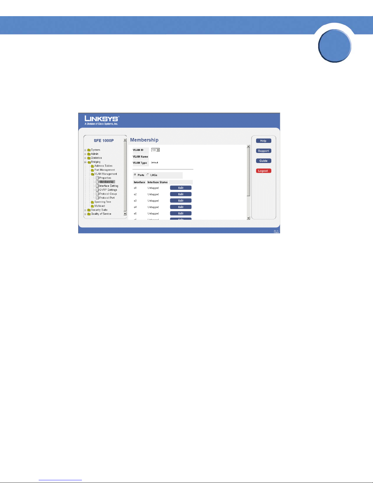
Chapter
SFE1000P Gigabit Ethernet Switch Administration Guide
Defining VLAN Membership
The VLAN Membership Page contains a table that maps VLAN parameters to ports. Ports are
assigned VLAN membership by toggling through the Port Control settings.
Membership Page
7
The Membership Page contains the following fields:
• VLAN ID — Displays the VLAN ID.
• VLAN Name — Displays the VLAN name.
• VLAN Type — Indicates the VLAN type. The possible field values are:
– Dynamic — Indicates the VLAN was dynamically created through GARP.
– Static — Indicates the VLAN is user-defined.
– Default — Indicates the VLAN is the default VLAN.
• Port — Indicates that ports are described in the page.
• LAG — Indicates that LAGs are described in the page.
• Interface — Displays the interface configuration being displayed.
• Interface Status — Indicates the interface’s membership status in the VLAN. The possible
field values are:
– Untagged — Indicates the interface is an untagged VLAN member. Packets forwarded
by the interface are untagged.
– Tagged — Indicates the interface is a tagged member of a VLAN. All packets forwarded
by the interface are tagged. The packets contain VLAN information.
Chapter 7: Configuring VLANs
Defining VLAN Membership
86
Page 95
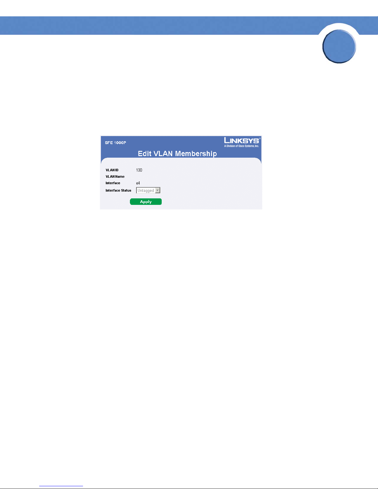
– Exclude — Excludes the interface from the VLAN. However, the interface can be added
to the VLAN through GARP.
– Forbidden — Denies the interface VLAN membership, even if GARP indicates the port is
to be added.
Modifying VLAN Membership
Edit VLAN Membership Page
Chapter
SFE1000P Gigabit Ethernet Switch Administration Guide
7
The Edit VLAN Membership Page contains the following fields:
• VLAN ID — Displays the VLAN ID.
• VLAN Name — Displays the VLAN name.
• Interface — Displays the port or LAG attached to the VLAN.
• Interface Status — Displays the current interface’s membership status in the VLAN. The
possible field values are:
– Untagged — Indicates the interface is an untagged VLAN member. Packets forwarded
by the interface are untagged.
– Tagged — Indicates the interface is a tagged member of a VLAN. All packets forwarded
by the interface are tagged. The packets contain VLAN information.
– Exclude — Excludes the interface from the VLAN. However, the interface can be added
to the VLAN through GARP.
– Forbidden — Denies the interface VLAN membership, even if GARP indicates the port is
to be added.
Chapter 7: Configuring VLANs
Defining VLAN Membership
87
Page 96

Chapter
SFE1000P Gigabit Ethernet Switch Administration Guide
Defining Interface Settings
The VLAN Interface Setting Page provides parameters for managing ports that are part of a VLAN.
The port default VLAN ID (PVID) is configured on the VLAN Port Settings page. All untagged packets
arriving to the device are tagged by the ports PVID.
Interface Setting Page
7
The VLAN Interface Setting Page contains the following fields:
• Port — Indicates that ports are described in the page.
• LAG — Indicates that LAGs are described in the page.
• Interface — The port or LAG number included in the VLAN.
• Interface VLAN Mode — Indicates the interface membership status in the VLAN. The
possible values are:
– General — The port belongs to VLANs, and each VLAN is user-defined as tagged or
untagged (full 802.1Q mode).
– Access — The port belongs to a single untagged VLAN. When a port is in Access mode,
the packet types which are accepted on the port (packet type) cannot be designated. It is
also not possible to enable/disable ingress filtering on an access port.
– Trunk — The port belongs to VLANs in which all ports are tagged (except for an
optional single native VLAN).
• PVID — Assigns a VLAN ID to untagged packets. The possible values are 2 to 4092, and
4095. Packets classified to the Discard VLAN are dropped.
• Frame Type — Packet type accepted on the port. Possible values are:
– Admit Tag Only — Indicates that only tagged packets are accepted on the port.
Chapter 7: Configuring VLANs
Defining Interface Settings
88
Page 97

Chapter
SFE1000P Gigabit Ethernet Switch Administration Guide
– Admit All — Indicates that both tagged and untagged packets are accepted on the port.
• Ingress Filtering — Ingress filtering discards packets which do not include an ingress port.
The possible values are:
– Enable — Ingress filtering is activated on the port.
– Disable — Ingress filtering is not activated on the port.
Modifying VLAN Interface Settings
Edit Ports Page
7
The Edit Ports Page contains the following fields:
• Interface — The port or LAG associated with this interface configuration.
• VLAN Mode — Indicates the port mode. Possible values are:
– General — The port belongs to VLANs, and each VLAN is user-defined as tagged or
untagged (full 802.1Q mode).
– Access — The port belongs to a single untagged VLAN. When a port is in Access mode,
the packet types which are accepted on the port (packet type) cannot be designated. It is
also not possible to enable/disable ingress filtering on an access port.
– Trunk — The port belongs to VLANs in which all ports are tagged (except for an
optional single native VLAN).
• PVID — Assigns a VLAN ID to untagged packets. The possible values are 2 to 4092, and
4095. Packets classified to the Discard VLAN are dropped.
• Frame Type — Packet type accepted on the port. Possible values are:
– Admit Tag Only — Indicates that only tagged packets are accepted on the port.
– Admit All — Indicates that both tagged and untagged packets are accepted on the port.
• Ingress Filtering — Ingress filtering discards packets which do not include an ingress port.
The possible values are:
Chapter 7: Configuring VLANs
Defining Interface Settings
89
Page 98

Chapter
SFE1000P Gigabit Ethernet Switch Administration Guide
– Enable — Ingress filtering is activated on the port.
– Disable — Ingress filtering is not activated on the port.
Configuring GVRP Settings
GARP VLAN Registration Protocol (GVRP) is specifically provided for automatic distribution of VLAN
membership information among VLAN-aware bridges. GVRP allows VLAN-aware bridges to
automatically learn VLANs to bridge ports mapping, without having to individually configure each
bridge and register VLAN membership.
To d ef ine GV RP:
NOTE: The Global System LAG information displays the same field information as the ports, but
represent the LAG GVRP information.
GVRP Settings Page
7
The GVRP Settings Page contains the following fields:
• GVRP Global Status — Indicates if GVRP is enabled on the device. The possible field values
are:
– Enable — Enables GVRP on the device.
– Disable — Disables GVRP on the device.
• Copy from Entry Number — Specifies the row number from which GVRP parameters are
copied.
• To Entry Number — Specifies the row to which the copied GVRP parameters are assigned.
• Port — Displays the GVRP configurations for specified port number.
• LAGs — Displays the GVRP configurations for LAGs.
Chapter 7: Configuring VLANs
Configuring GVRP Settings
90
Page 99

Chapter
SFE1000P Gigabit Ethernet Switch Administration Guide
• Interface — Indicates the interface for which the GVRP configuration is displayed.
• GVRP State — Indicates if GVRP is enabled on the interface. The possible field values are:
– Enabled — Enables GVRP on the selected interface.
– Disabled — Disables GVRP on the selected interface.
• Dynamic VLAN Creation — Indicates if Dynamic VLAN creation is enabled on the interface.
The possible field values are:
– Enabled — Enables Dynamic VLAN creation on the interface.
– Disabled — Disables Dynamic VLAN creation on the interface.
• GVRP Registration — Indicates if VLAN registration through GVRP is enabled on the device.
The possible field values are:
– Enabled — Enables GVRP registration on the device.
7
– Disabled — Disables GVRP registration on the device.
Modifying GVRP Settings
Edit GVRP Page
The Edit GVRP Page contains the following fields:
• Interface — Displays the interface on which GVRP is enabled. The possible field values are:
– Port — Indicates the port number on which GVRP is enabled.
– LAG — Indicates the LAG number on which GVRP is enabled.
• GVRP State — Indicates if GVRP is enabled on the interface. The possible field values are:
– Enable — Enables GVRP on the selected interface.
– Disable — Disables GVRP on the selected interface.
• Dynamic VLAN Creation — Indicates if Dynamic VLAN creation is enabled on the interface.
The possible field values are:
Chapter 7: Configuring VLANs
Configuring GVRP Settings
91
Page 100

Chapter
SFE1000P Gigabit Ethernet Switch Administration Guide
– Enable — Enables Dynamic VLAN creation on the interface.
– Disable — Disables Dynamic VLAN creation on the interface.
• GVRP Registration — Indicates if VLAN registration through GVRP is enabled on the device.
The possible field values are:
– Enable — Enables GVRP registration on the device.
– Disable — Disables GVRP registration on the device.
Defining VLAN Protocol Group
The Protocol Group Page contains information defining protocol names and the VLAN Ethernet type.
Interfaces can be classified as a specific protocol based interface.
Protocol Group Page
7
The Protocol Group Page contains the following fields:
• Protocol Value — Displays the User-defined protocol name.
• Group ID (Hex) — Defines the Protocol group ID to which the interface is added. Range is 1-
2147483647.
Chapter 7: Configuring VLANs
Defining VLAN Protocol Group
92
 Loading...