

Page 1
LINKSYS ONE COMMUNICATIONS SOLUTION
Customer Premises Equipment
Administration Guide
Release 2.1
Page 2

© 2007 Cisco Systems, Inc. All rights reserved. Cisco, the Cisco logo, Cisco Systems, Linksys, and Linksys One are trademarks or registered trademarks of Cisco Systems, Inc.
and/or its affiliates in the United States and certain other countries. All other trademarks mentioned in this document or Website are the property of their respective owners.
The use of the word partner does not imply a partnership relationship between Cisco or Linksys and any other company. (0704R)
Page 3

Linksys One Communications Solution
Contents
Chapter 1: Welcome to Linksys One - - - - - - - - - - - - - - - - - - -1
Welcome VARs! 1
About this Guide 1
Chapter 2: Using the Linksys One Portal - - - - - - - - - - - - - - - - -3
Understanding the Linksys One Portal 3
Where are Passwords Set? 4
Accessing the Linksys One Portal 4
Getting Online Help 5
Chapter 3: Configuring Your System - - - - - - - - - - - - - - - - - - -6
Chapter 4: Viewing System Information - - - - - - - - - - - - - - - - -8
Viewing Brand Information 8
Viewing Account Information 8
Viewing Services Router Information 8
Chapter 5: Managing Accounts - - - - - - - - - - - - - - - - - - - - -9
Resetting User Passwords 9
Managing Admin Accounts 10
Managing System Passwords 11
Chapter 6: Using the Phone Application - - - - - - - - - - - - - - - - 12
How do I change a setting? 12
When do my changes take effect? 13
Online Help 13
Finding Your Way Home 13
Navigating with the Tab Index 13
Understanding Visual Cues on the Phone Application Screens 14
Setting Install Time Configuration 15
Viewing and Configuring Trunks 15
Configuring FXO Devices 17
i
Page 4

Configuring FXS Devices 19
Viewing Phone Devices 20
Viewing Application Device Status 21
Defining Groups 23
Defining Roles 26
Defining Dialing Patterns 29
Configuring Site Settings 32
Setting Site Options 33
Defining Auto Attendant Hours 36
Defining Auto Attendant Days 38
Configuring Email 40
Managing Users 43
Assigning Names to Users 43
Assigning Users to Groups 45
Assigning Users to Roles 46
Assigning Permissions to Users 49
Assigning SNR to Users 51
Assigning Assistants to Users 55
Forwarding Calls 57
Assigning Trunks to Users 60
Assigning Devices 64
Changing Individual User Settings and Templates 65
Changing User Settings 66
Changing User Templates 73
Configuring and Viewing Call Target Information 77
Viewing Group Information 78
Viewing Role Information 79
Defining System Voicemail Boxes 80
Assigning Inbound Trunks to Call Targets 82
Configuring Call Forward Options 84
Viewing System Information 87
Linksys One Communications Solution
Chapter 7: Viewing the Surveillance Application - - - - - - - - - - - - 89
Adding a Camera to the Administration Interface 90
Removing a Camera from the Administration Interface 91
To Access the Camera Software 92
ii
Page 5

Linksys One Communications Solution
Chapter 8: Managing Data Devices - - - - - - - - - - - - - - - - - - 94
Viewing the Status of Data Devices 94
Pinging a Data Device 95
Adding DNS Names for Static IP Devices 95
Allowing Access to Network Services 96
Exposing a Network Device as a DMZ Host 98
Using the Services Router Advanced Interface 98
Chapter 9: Using the VAR View Screens - - - - - - - - - - - - - - - 100
Changing the Services Router Connectivity Settings 100
Viewing the Maintenance Status 101
Backing up and Restoring your Services Router 103
Changing a Service Node Account 103
Viewing Device Snapshots 104
Configuring Wireless 105
Chapter 10: Using the Support View Screens - - - - - - - - - - - - - 106
Changing a Service Node Account 107
Backing Up and Restoring Your CPE Configuration 108
Viewing Provisioning Settings 109
Viewing Device Snapshots 110
Changing the Services Router Connectivity Settings 112
Viewing VPN Status 114
Displaying Services Router Information 115
Viewing the IP Address and MAC Address 116
Cleaning User Information from the Services Router 116
Cleaning the Customer and Account Information from the Services Router 117
Restarting the Services Router 117
Viewing the Maintenance Status 118
Re-imaging the CPE 119
Restarting All Phones 119
Viewing Phone Device Data 120
Chapter 11: Viewing Linksys One-Ready Devices - - - - - - - - - - - 121
Displaying Devices 121
Device Info Screen 123
iii
Page 6

Device Commands 124
Showing Details 125
Showing Syslogs 126
Chapter 12: Viewing Site Status - - - - - - - - - - - - - - - - - - -128
WAN Status 128
Device Status 129
VPN Status 131
SVR Download Status 131
Appendix A: Where Can I Find More Information? - - - - - - - - - - -132
Linksys One Documents 132
Linksys One Ready Documents 136
Linksys Partner Connection Portal 137
How to Become a Linksys Connected Partner 137
How to Access the Linksys Partner Connection Portal 137
Appendix B: Linksys One Contact Information - - - - - - - - - - - - -138
Appendix C: Troubleshooting - - - - - - - - - - - - - - - - - - - - -139
Troubleshooting Installation 139
Troubleshooting the Services Router 140
Troubleshooting the Voice Gateway 143
Troubleshooting Connected Devices 145
Linksys One Communications Solution
iv
Page 7

Linksys One Communications Solution
Automatic Configuration
Linksys One uses a network discovery process
with automated configuration which means that
new networks—as well as moves, adds, and
changes—are fast and easy. As soon as they are
plugged in, Linksys One devices automatically
determine the optimal configuration and are
ready to go.
1
Chapter
Welcome to Linksys One
Thank you for choosing Linksys One, a complete, affordable, easy-to-install communications
solution for small businesses. Linksys One delivers telephones, data networking,
applications, and the Internet through one high-speed connection from a Hosted Service
Provider (HSP). The system provides IP-based voice and data services with built-in security,
reliability and premium call quality. With Linksys One, the network instantly detects new
Linksys One devices and automatically configures them for optimal performance and simple
management. Phones install in minutes, not the hours or days it takes with other solutions.
Welcome VARs!
Linksys One delivers the communications solutions your customers want at the price they
need. As your customers’ businesses grow, you can help them easily connect new users, and
sell additional technologies, such as network attached storage, while enabling the customer
to protect their original investment. For example, Linksys One carriers will offer future high-
value Internet-based application services that provide smarter ways to transact business.
Linksys One resellers can leverage this momentum and create a foundation to sell additional
services. For resellers, this is a great opportunity to grow your revenue and profit potential.
You can capitalize on the growing demand for IP-based services with a more affordable,
simpler and complete small business communications solution.
About this Guide
The Linksys One Customer Premises Equipment Administration Guide is intended for
qualified Value Added Resellers (VARs) who are installing, administering, and managing the
Linksys One customer premises equipment (CPE). The guide assumes you have completed
the Linksys One training and are familiar with all system software configuration and
hardware installation procedures. The following topics are included:
• Chapter 1 "Welcome to Linksys One" provides an overview of this guide.
• Chapter 2 "Using the Linksys One Portal" describes how to use the Linksys One
Portal to customize site-wide, voice, and data settings.
• Chapter 3 "Configuring Your System" describes how to configure your Linksys One
system if you are using it for the first time.
Chapter 1: Welcome to Linksys One
Welcome VARs!
1
Page 8

• Chapter 4 "Viewing System Information" describes the contents of the Info screen on
the Linksys One Portal. The Info screen shows the Brand, Account, and SVR
information.
• Chapter 5 "Managing Accounts" describes the contents of the Accounts screen on
the Linksys One Portal which includes information on managing Administrator
accounts.
• Chapter 6 "Using the Phone Application" describes the contents of the Phone
Application screen on the Linksys One Portal.
• Chapter 7 "Viewing the Surveillance Application"describes the Surveillance
Application.
• Chapter 8 "Managing Data Devices" describes the contents of the Data Devices
screen on the Linksys One Portal.
• Chapter 9 "Using the VAR View Screens" describes the contents of the VAR View
screen on the Linksys One Portal.
• Chapter 10 "Using the Support View Screens" describes the contents of the Support
View screen on the Linksys One Portal.
Linksys One Communications Solution
1
Chapter
• Chapter 11 "Viewing Linksys One-Ready Devices" describes the contents of the L1
Devices screen on the Linksys One Portal.
• Chapter 12 "Viewing Site Status" describes the contents of the Site Status screen on
the Linksys One Portal.
2
Chapter 1: Welcome to Linksys One
About this Guide
Page 9

Linksys One Communications Solution
System Requirements
To use the Linksys One Portal, you’ll need to
install the following programs on your
computer:
• Macromedia Flash 8.0 or greater
• Microsoft Internet Explorer, version
5.5 or 6
• Mozilla FireFox 1.5 or greater
2
Chapter
Using the Linksys One Portal
Administering the Linksys One communications solution is easy! Although most system
settings are already set for you, you can use the web-based Linksys One Portal to customize
settings for your customer’s site, users, and network. The Linksys One Portal can be accessed
locally or remotely to customize all CPE voice features and a subset of CPE data features.
The Linksys One Portal also includes a web-page that end-users can access to change their
passwords, set personal call forwarding options, configure their auto dials, plus more.
Understanding the Linksys One Portal
The Linksys One Portal shows different functions, shown in tabs, that are displayed
depending on the login level. For example, when logged in as a User, only the Accounts and
Phone Application function tabs are shown. When logged in as Support, all function tabs
are shown.
A complete listing of available functions in relation to the login level is shown in the table
below.
Info Accounts Phone
Application
User **
Data Devices VAR Vi ew Support View L1 Devices Site Status
Administrator X X * * X
Install XXXXX*XX
Support X X X X X X X X
* An abbreviated version of the application appears.
Chapter 2: Using the Linksys One Portal
Understanding the Linksys One Portal
3
Page 10
Linksys One Communications Solution
Where are Passwords Set?
Passwords for the different login levels are set as follows:
• User—User passwords are set by the user. The default user password is “3” (steering
digit) plus “extension number.” For example, if the extension is 700, then the default
password is 3700. Once users log into the to the Portal, they are prompted to
change their password; it is recommended that users change their default password
for security reasons. User passwords can be reset to their default value in the
Accounts > Reset User Password screen.
• Administrator—Administrator passwords are configured in the Accounts > Manage
Admin Accounts screen.
• Install—The support password is set on the Service Node.
• Support—The support password is set on the Service Node.
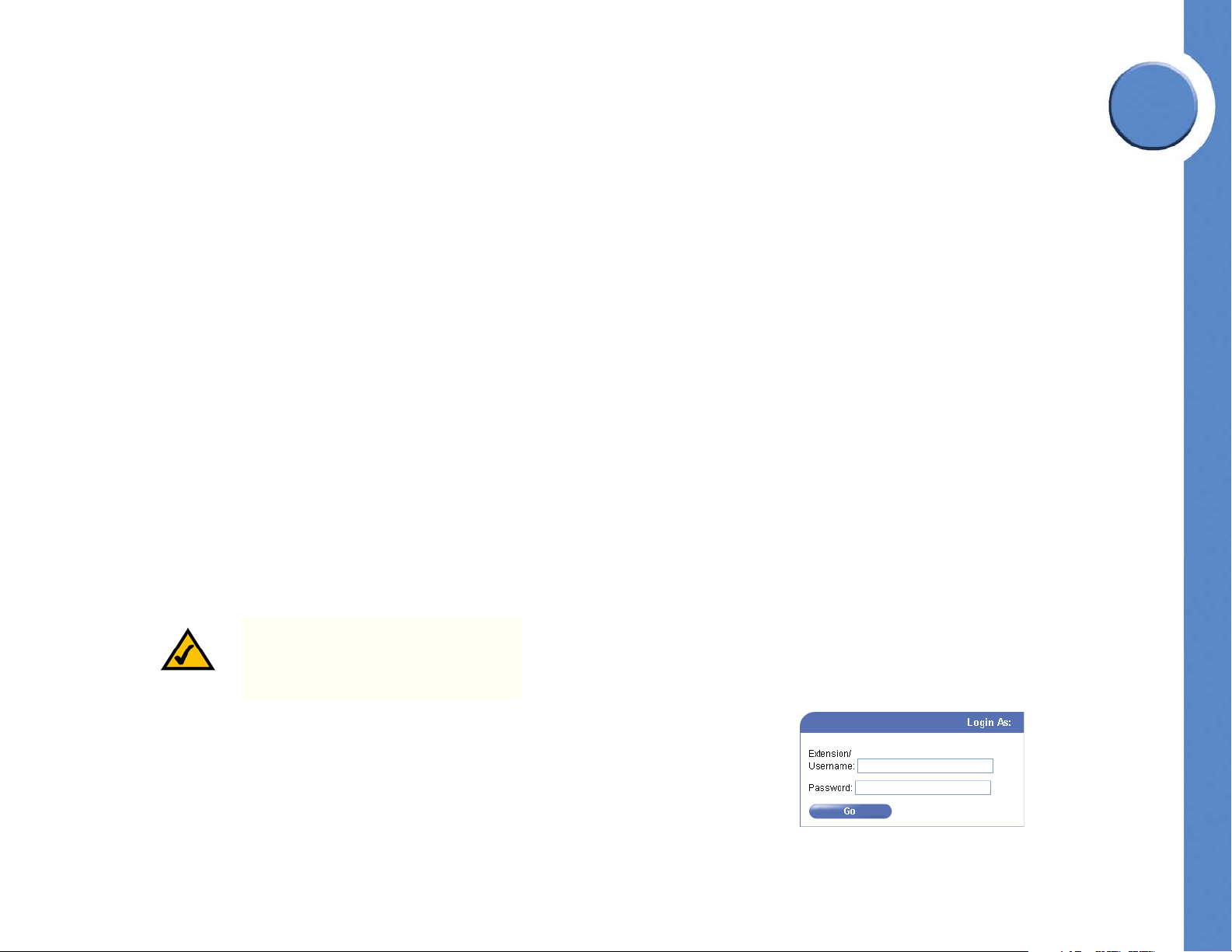
Accessing the Linksys One Portal
Here’s how to access and use the Linksys One Portal to customize your phone system.
1. Open a browser and type the IP address for the Services Router as follows:
• If you are accessing the Linksys One Portal on a computer that is connected to a LAN
port on the Services Router, type:
2
Chapter
https://L1admin
NOTE: Depending on the security
settings of some networks, you may
need to type https://L1admin.home
• If you are accessing the Linksys One Portal on a computer that is remote from the
Services Router, type the IP address of the Services Router in the format:
https://proxy.<customer number>.<brand domain>:51
2. In the Linksys One Portal login window, type a username and password and click Go.
4
Chapter 2: Using the Linksys One Portal
Where are Passwords Set?
Page 11
2
Chapter
Linksys One Communications Solution
After successful login, the main screen appears.
Getting Online Help
For the Phone application, each page in the Linksys One Portal includes a Help button that
provides quick answers to questions you may have about entering information on the
associated page. Simply click the Help button to display help for that page.
Chapter 2: Using the Linksys One Portal
Accessing the Linksys One Portal
5
Page 12

Linksys One Communications Solution
Configuring Your System
If you are configuring your Linksys One system for the first time, you can use the following
steps to ensure optimal operation. Here you will configure users, define hours of operation,
set up voicemail, configure devices, and assign passwords.
To Configure Linksys One
1. Configure steering digits and the site caller ID using the Install > Dialing screen. Refer to
”Defining Dialing Patterns” section on page 29.
2. Add users in the Users > User Directory screen. Refer to ”Assigning Names to Users”
section on page 43.
3. Configure Users
a. Set up user permissions in the Users > Permissions screen. Refer to ”Assigning
Permissions to Users” section on page 49.
b. Assign numbers to users’ phones in the Users > Inbound Trunks screen. Refer to
”Assigning Trunks to Users” section on page 60.
c. (Optional) Define Groups and Roles in the Install > Define Groups and Install >
Define Roles screens. Refer to ”Defining Groups” section on page 23 and ”Defining
Roles” section on page 26.
3
Chapter
d. (Optional) Assign users to groups and roles in the Users > Group Assignments and
Users > Role Assignments screens. Refer to ”Assigning Users to Groups” section on
page 45 and ”Assigning Users to Roles” section on page 46.
e. (Optional) Assign Assistants to Users in the Users > Assistants screen. Refer to
”Assigning Assistants to Users” section on page 55.
f. (Optional) Assign phone numbers to groups and roles in the Call Targets > Inbound
Trunks screen. Refer to ”Assigning Inbound Trunks to Call Targets” section on
page 82.
g. (Optional) Set up call forwarding and voicemail options for groups and roles in the
Call Targets > Call Forwards and Call Targets > Voicemail screens. Refer to
6
Chapter 3: Configuring Your System
Page 13

3
Chapter
Linksys One Communications Solution
”Configuring Call Forward Options” section on page 84 and ”Defining System
Voicemail Boxes” section on page 80.
4. (Optional) Change the time for the nightly maintenance window in the Site > Settings
screen. Refer to ”Configuring Site Settings” section on page 32.
5. Set AutoAttendant Days and Hours in the Site > AA Days and Site > AA Hours screens.
Refer to ”Defining Auto Attendant Days” section on page 38 and ”Defining Auto
Attendant Hours” section on page 36.
6. Record AutoAttendant greetings (dial the AA Admin number, which, by default is 4x98,
where 4 is a steering digit and x is a number of zeroes (0s), depending on the site
mask). The AA Admin default password is the same as the AA Admin number.
7. Associate physical phones to users in the Users > Device Assignments screen (phones
are identified by MAC address). If users were pre-configured for this installation, this
step may not be required. Refer to ”Assigning Devices” section on page 64.
8. Continue with site-specific custom configuration. For example:
a. Configure FXO devices in the Install > FXO Devices screen. Refer to ”Configuring
FXO Devices” section on page 17.
b. Configure FXS devices (can be fax, phone or paging) in the Install > FXS Devices
screen. Refer to ”Configuring FXS Devices” section on page 19.
9. Create Admin accounts, as needed in the Accounts > Manage Admin Accounts screen.
Refer to ”Managing Admin Accounts” section on page 10.
10. Change system passwords, as needed in the Accounts > Manage System Passwords
screen. Refer to ”Managing System Passwords” section on page 11.
Chapter 3: Configuring Your System
7
Page 14
Linksys One Communications Solution
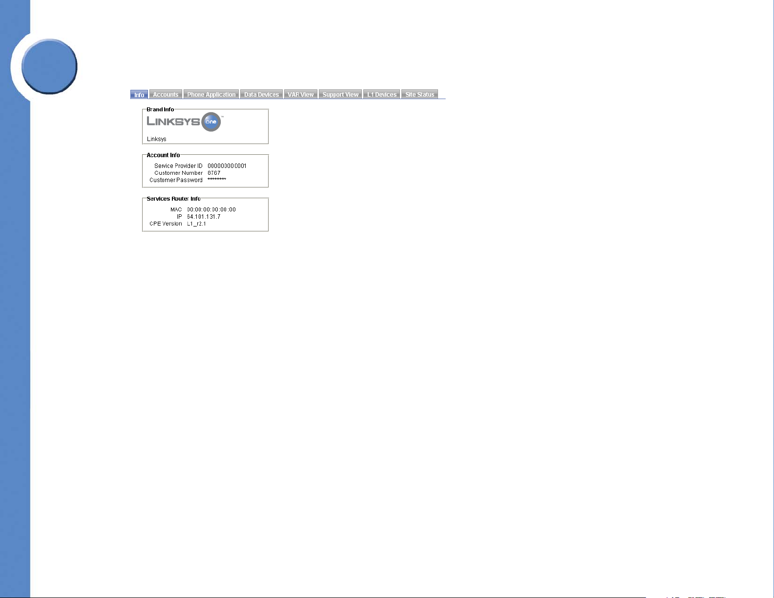
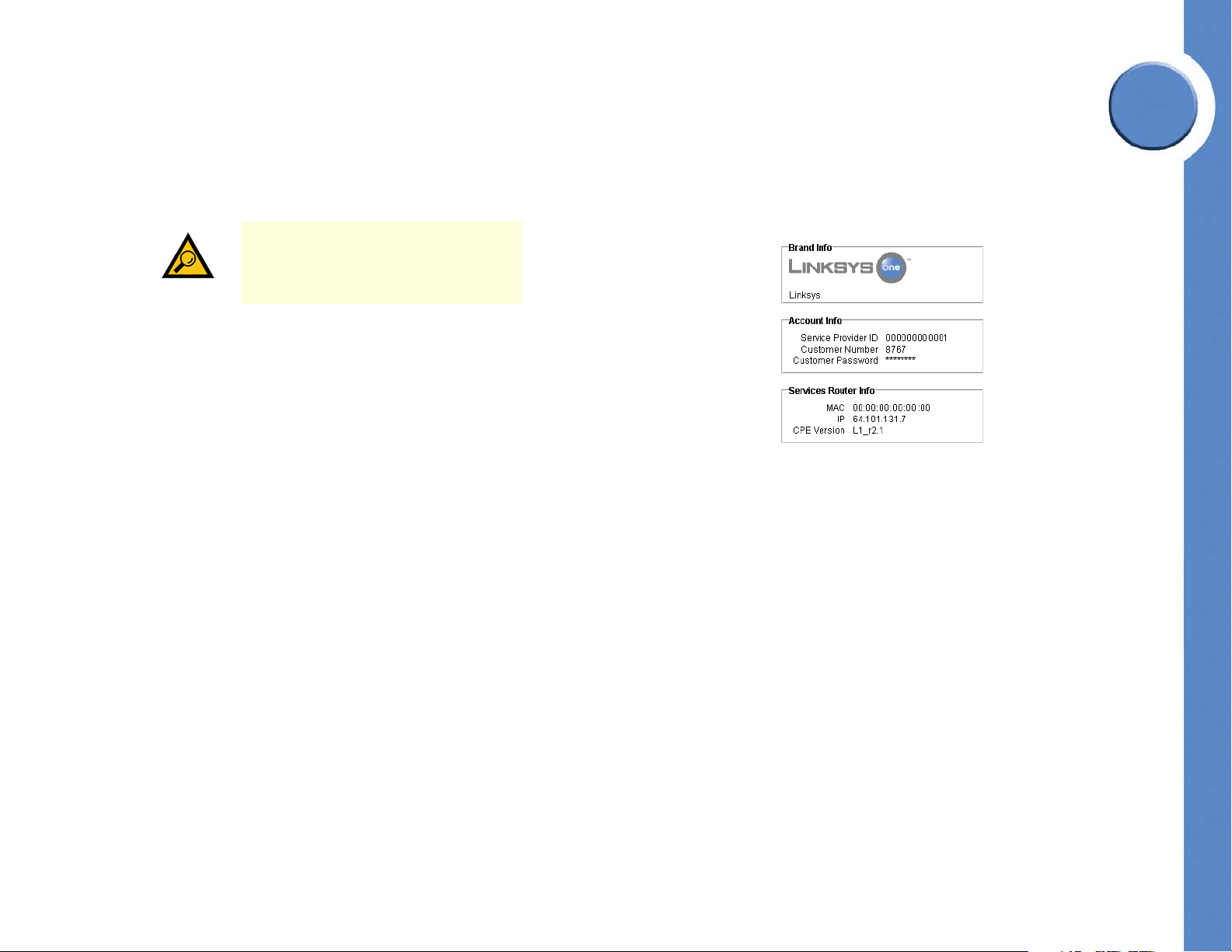
Viewing System Information
The Info screen shows the Brand, Account, and Services Router information. This information
is display-only; no changes can be made here.
TIP: Before logging in, the Info screen is
also available from the Admin, Install,
or Support roles.
Viewing Brand Information
The Brand Information area shows the name of the brand and the logo that displays on the
phones at the customer’s site. This information is configured on the Service Node. For more
information regarding brands and brand logos, refer to the Service Node System
Administration Guide, available on the Linksys Partners Connection (LPC) portal. Refer to
”Linksys Partner Connection Portal” section on page 137 for more information about the
LPC.
Viewing Account Information
The Account Information area shows the Service Provider ID, Customer Number, and
Customer Password. For security purposes, the customer password is not shown in this
screen.
4
Chapter
Viewing Services Router Information
The Services Router Information area shows the MAC address, IP address, and the CPE
software version currently running on the Services Router.
8
Chapter 4: Viewing System Information
Viewing Brand Information
Page 15
Linksys One Communications Solution
5
Chapter
Managing Accounts
The Accounts screens allows you to reset a user or system password and manage
administration accounts. This tab contains three functions: Reset User Password, Manage
Admin Accounts, and Manage System Passwords.
These sections help you use the Accounts features:
• ”Resetting User Passwords” section on page 9
• ”Managing Admin Accounts” section on page 10
• ”Managing System Passwords” section on page 11
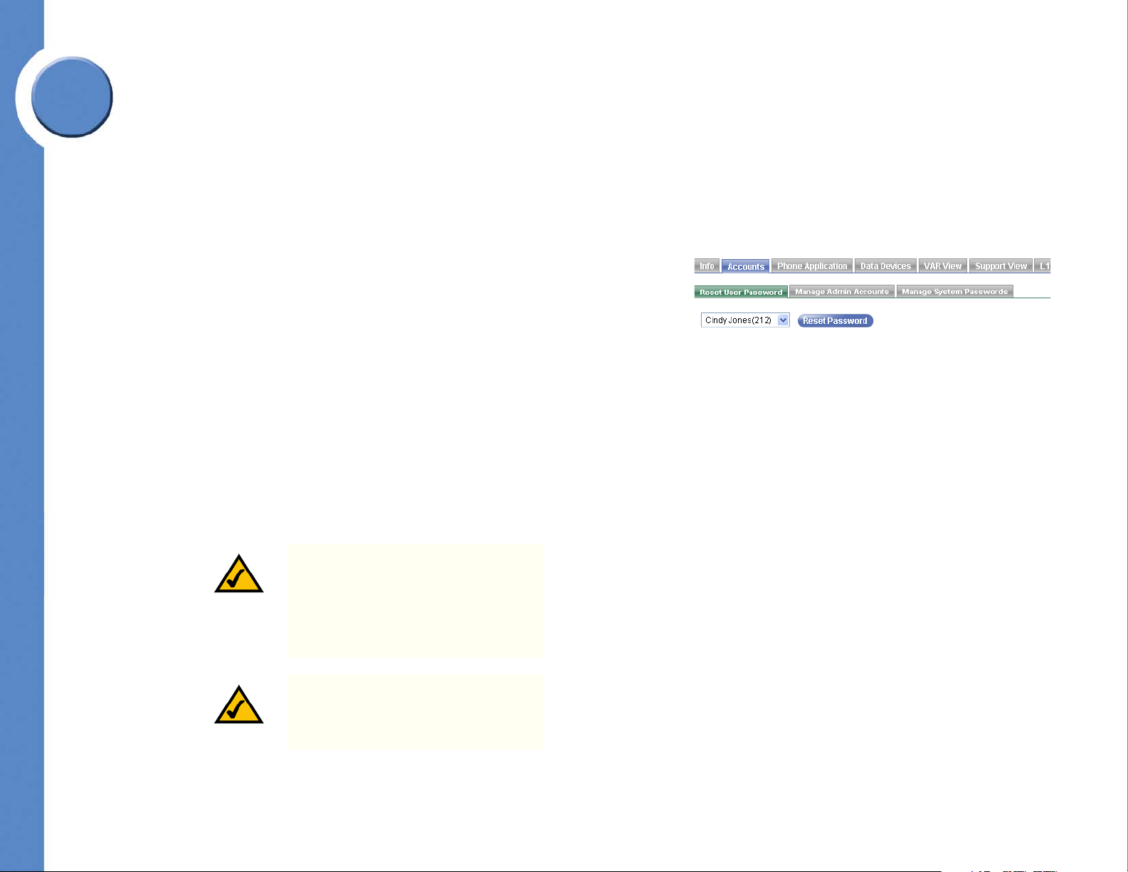
Resetting User Passwords
The Reset User Password screen allows you to reset a password for a selected user. If you are
logged in as a user, you can change the password only for that user. If you are logged in as
Admin or above, you can reset any user passwords.
To reset a user password:
1. Click Accounts > Reset User Password.
2. Select a user for which you want to change the password.
NOTE: The default password for the
Auto Attendant is 498 (for a 4XX
steering digit pattern). Add “0” after the
“4” for longer patterns. For example,
for a pattern of 4XXX, the password is
4098.
NOTE: The default password for the
operator voicemail box is 3450.
Chapter 5: Managing Accounts
Resetting User Passwords
9
Page 16
3. Click Reset Password. The password for the user changes to its default setting.
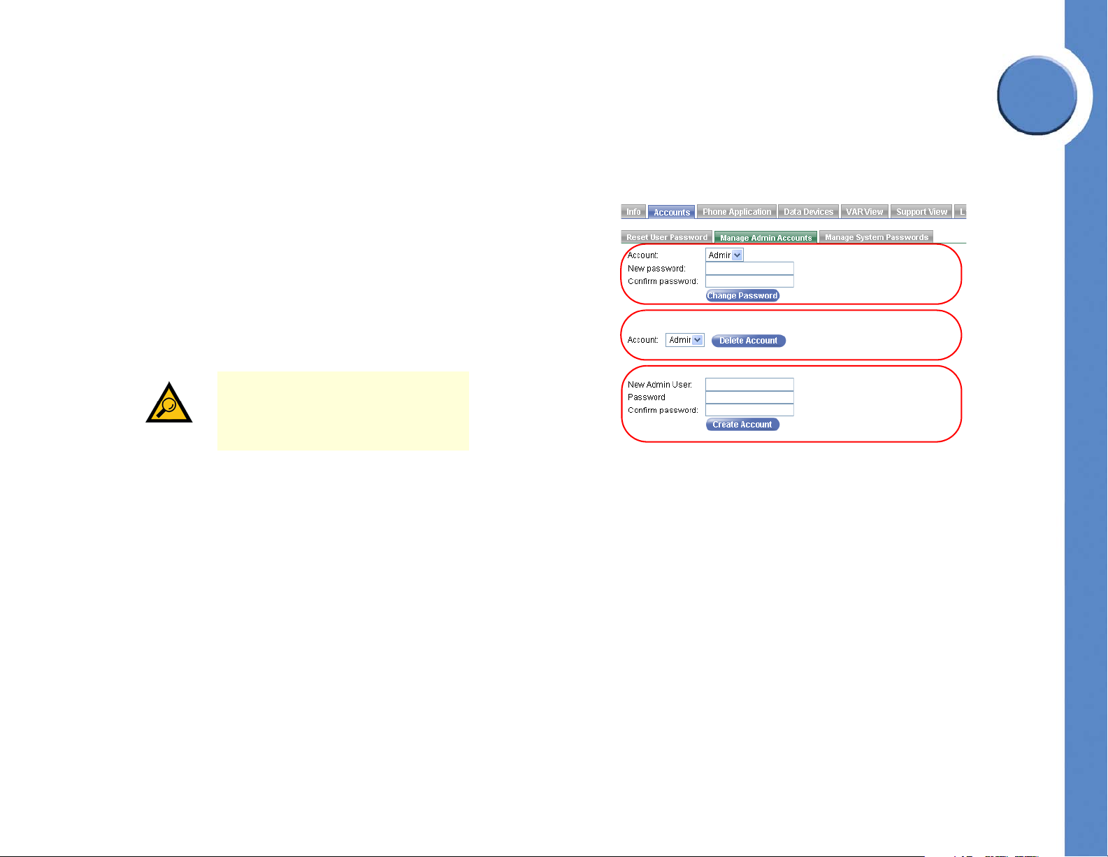
Existing Account Area
Delete Account Area
New Account Area
Managing Admin Accounts
The Manage Admin Accounts screen allows you to change a password for an existing
Admin account, create a new Admin account, or delete an Admin account. This screen is
available only when logged in as Install or Support.
To change an Admin password:
1. Click Accounts > Manage Admin Accounts.
2. In the Existing Account area, select an Admin account for password change.
3. Type a new password in the New Password area.
4. Retype the password in the Confirm Password area.
TIP: The password is case-sensitive and
can be any combination of letters and
numbers. Special characters such as “!”
and “&” cannot be used.
Linksys One Communications Solution
5
Chapter
5. Click Change Password.
To delete an Admin account:
1. Click Accounts > Manage Admin Accounts.
2. In the Delete Account area, select an Admin account to delete.
3. Click Delete Account.
To create a new Admin account:
1. Click Accounts > Manage Admin Accounts.
2. In the New Account area, type a new Admin name.
3. Type a password in the Password area.
10
Chapter 5: Managing Accounts
Managing Admin Accounts
Page 17
5
Linksys One Communications Solution
4. Retype the password in the Confirm Password area.
TIP: The password is case-sensitive and
can be any combination of letters and
numbers. Special characters such as “!”
and “&” cannot be used.
Chapter
5. Click Create Account.
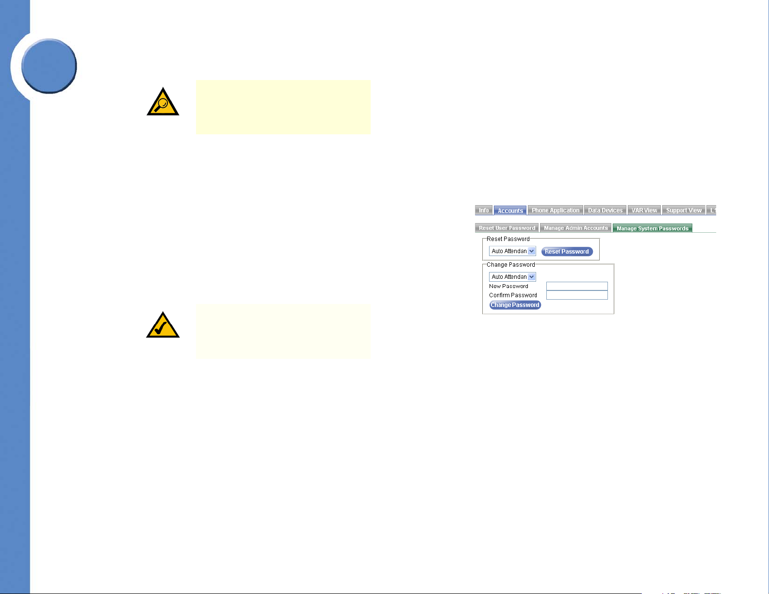
Managing System Passwords
The Manage System Passwords screen allows you to reset or change a password for the
Auto Attendant or system voicemail boxes. This screen is only available when logged in as
Admin level and above.
To reset a system or voicemail box password:
1. Click Accounts > Manage System Passwords.
2. In the Reset Password area, select the Auto Attendant or a voicemail box.
NOTE: The default password for the
Auto Attendant is 4x99. The default
password for system voicemail is 4x98.
Where “x” is a padding zero.
3. Click Reset Password. The password for the Auto Attendant or voicemail box changes to
its default setting.
To change a system or voicemail box password:
1. Click Accounts > Manage System Passwords.
2. In the Change Password area, select the Auto Attendant or a voicemail box.
3. Type a new password in the New Password area.
4. Retype the password in the Confirm Password area.
5. Click Reset Password.
Chapter 5: Managing Accounts
Managing System Passwords
11
Page 18
Linksys One Communications Solution
Using the Phone Application
The Phone Application allows you to manage the Linksys One phones, devices, and user
settings.
These sections help you use the Phone application:
• ”Finding Your Way Home” section on page 13
• ”Setting Install Time Configuration” section on page 15
• ”Configuring Site Settings” section on page 32
• ”Managing Users” section on page 43
• ”Changing Individual User Settings and Templates” section on page 65
• ”Configuring and Viewing Call Target Information” section on page 77
• ”Viewing System Information” section on page 87
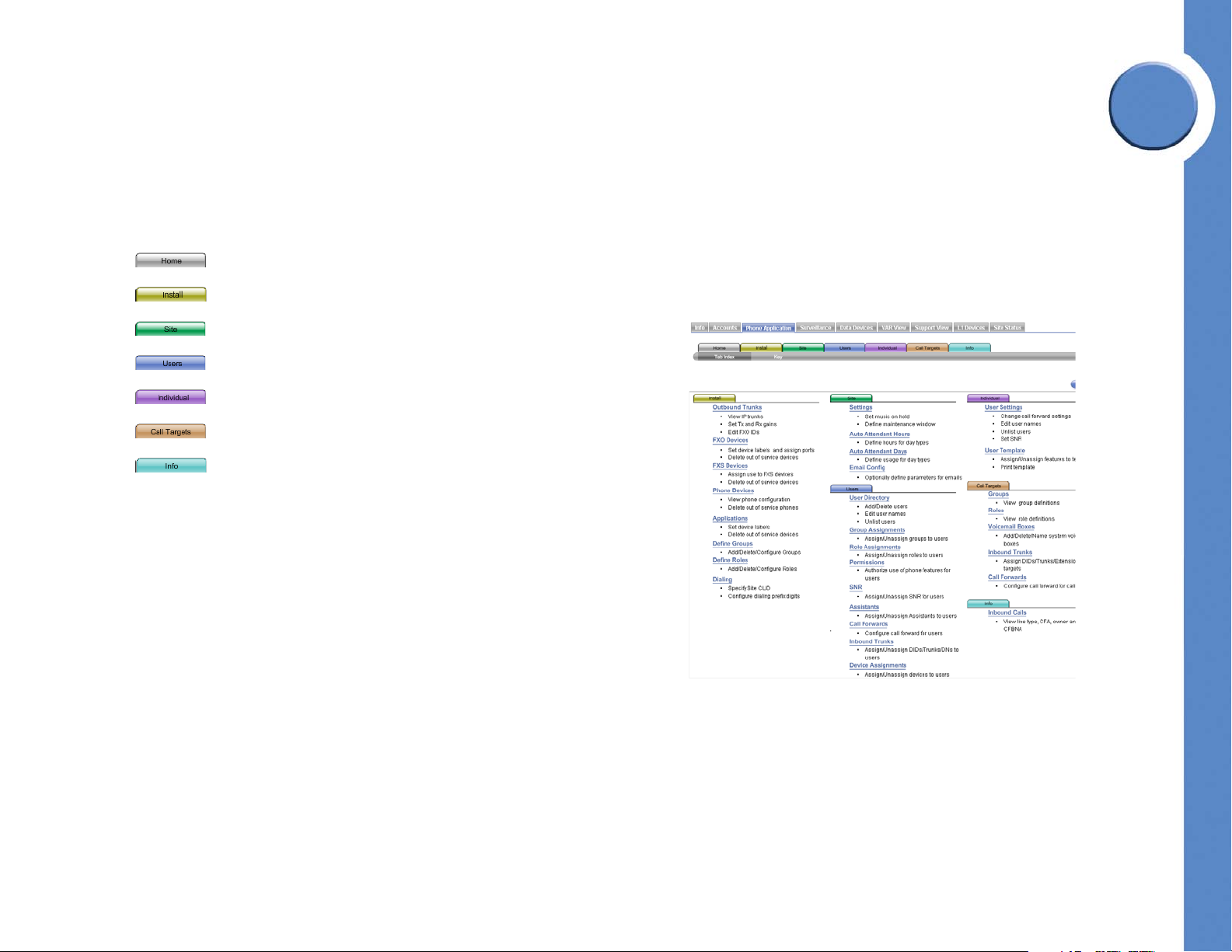
Once you login to the Phone Application, you’ll see the Tab In de x window that shows you all
the available features for the Phone Application. Simply click any hyperlinked item in the list
to go directly to the window where you can configure that setting.
6
Chapter
How do I change a setting?
1. Click an action you want to perform. Alternatively, you can click a Phone Application
tab to see a menu bar for that topic. For example, click the Users tab to view the menu
bar with options for configuring your users.
2. Make your changes.
3. Click Commit to submit your changes or click Cancel to discard all changes for this
window.
4. To change settings on a different window, click one of the Phone Application tabs, or
click the Home tab to return to the Tab Index window.
12
Chapter 6: Using the Phone Application
How do I change a setting?
Page 19

Linksys One Communications Solution
6
Chapter
When do my changes take effect?
Depending on the type of change, some changes take effect immediately when you click
Commit while others require the phone or system to restart before they take effect. After you
commit a change, click Changes Pending or System Changes Pending to see which
changes are not yet active and the time they will take effect. If you want the changes to take
effect immediately, click Restart Phone (for changes pending) or Restart System (for system
changes pending). Otherwise, the changes will not go into effect until the next system
maintenance window.
IMPORTANT: Restarting the system will
cause a brief loss of phone and data
services.
Online Help
Each page in the Phone Application includes a Help button that provides quick answers to
questions you may have about entering information on the associated page. Simply click the
Help button to display help for that page.
Finding Your Way Home
By default, the Phone Application opens to the Home screen. From this screen you can see
the Tab Index and go to the Key screen which explains graphical elements and visual cues
used throughout the Phone Application. To go back to the Home page from any other
location, click the Home tab.
Navigating with the Tab Index
The Tab Index is the first screen that opens when you start the Phone Application. It contains
an index of the Phone Application features. An expanded view of the tabs is located below
the row of tabs. To navigate to a different screen, click on its hyperlinked title or click on one
of the tabs on top of the Tab Index screen.
Chapter 6: Using the Phone Application
Finding Your Way Home
13
Page 20

Linksys One Communications Solution
Understanding Visual Cues on the Phone Application Screens
Graphical elements are used in the windows to indicate various items in the application.
Click Key on the Home tab to display a description how items, colors, and visual cues are
used.
6
Chapter
14
Chapter 6: Using the Phone Application
Finding Your Way Home
Page 21
Linksys One Communications Solution
6
Chapter
Setting Install Time Configuration
The Install tab in the Phone Application lets you configure trunks, devices, applications,
groups, and roles for your customer’s site. You can also configure dialing settings for the
user’s phones.
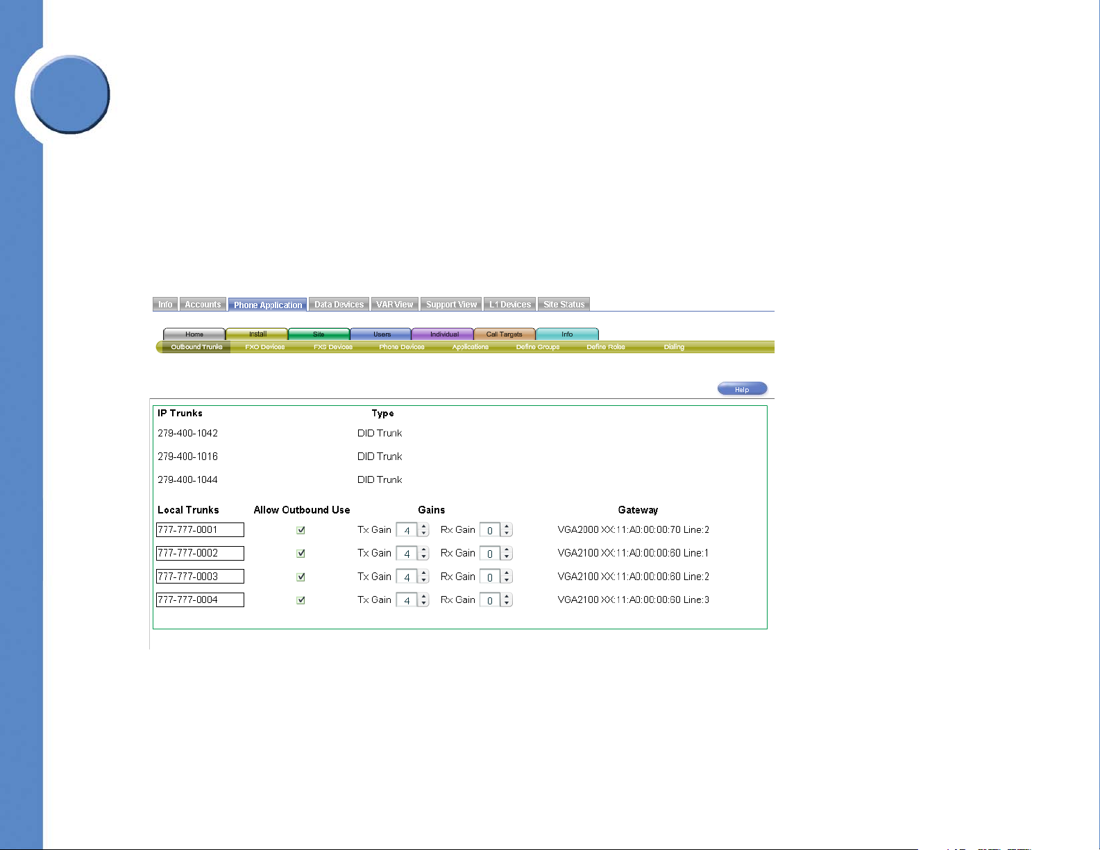
Viewing and Configuring Trunks
The Outbound Trunks screen allows you to view the IP trunks assigned to this site, specify
labels to identify local trunks, allow local trunk usage for outbound calls, and set the gain of
the local trunks.
Chapter 6: Using the Phone Application
Setting Install Time Configuration
15
Page 22
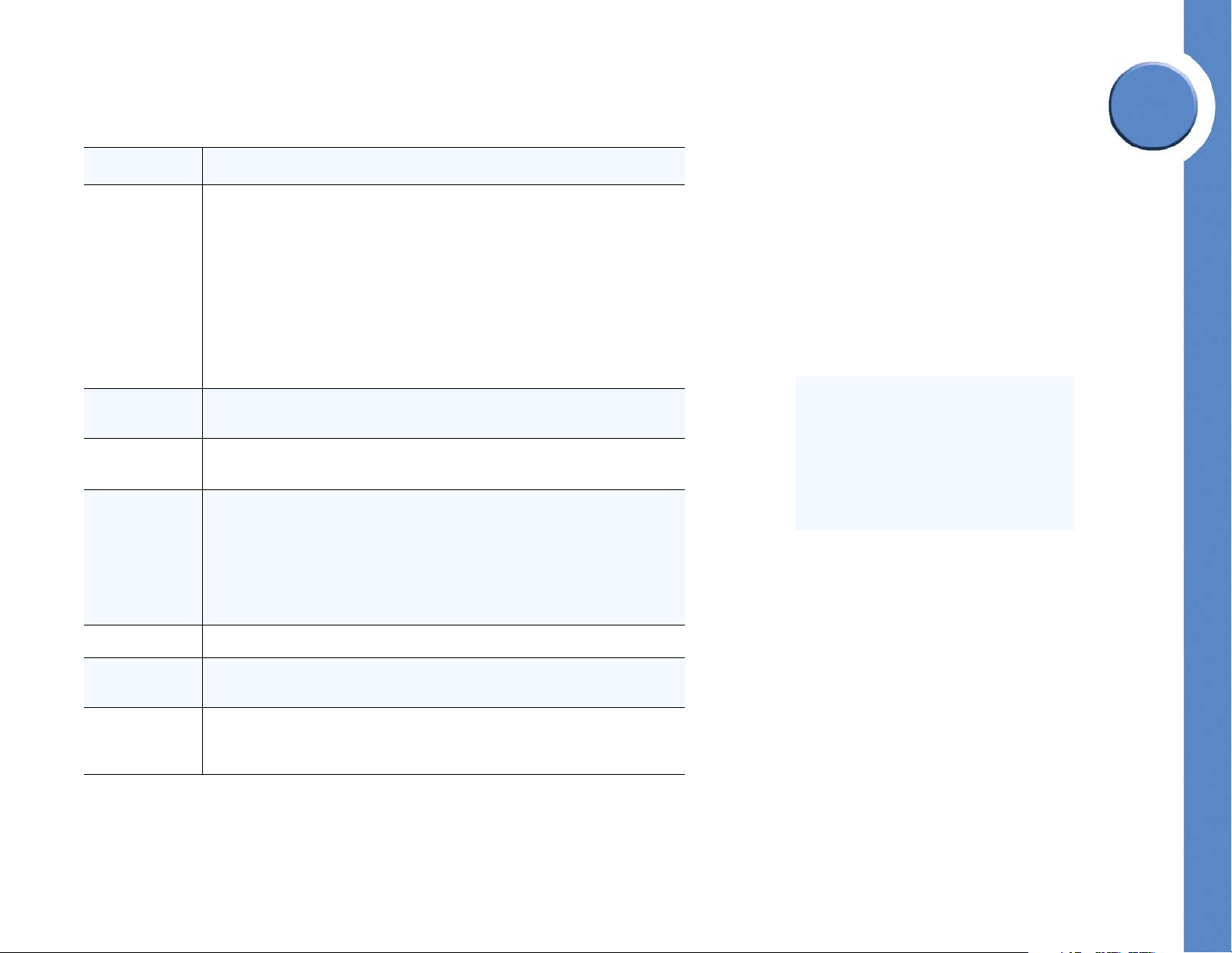
Refer to the following table for a description of the information displayed in the Outbound
screen.
Linksys One Communications Solution
6
Field Description
IP Trunks The IP trunks assigned to this site by the Service Node. These are automatically
downloaded to the site and updated during the maintenance window.
Type The type of IP trunk. There are two types of IP trunks: DID and non-DID. A Direct
Inward Dial (DID) number is an externally reachable number that can be
assigned as a primary extension. A non-DID trunk cannot be assigned as a
primary extension.
Local Trunks The list of discovered PSTN connected local FXO trunks on this site that are
connected either to a VGA2000 or VGA2100 gateway. This area also allows
you to set transmit and receive gain of the trunks.
Allow Outbound
Use
Gains The transmit (Tx Gain) and receive (Rx Gain) gain settings of the local trunk.
Gateway The model number, Media Access Control (MAC) address, and line number of
To assign a label to a local trunk:
Allows this local trunk to be placed in the outbound trunks pool and used with
the Local Trunk steering digit. Note: FXO trunks will not be discovered or listed
unless they are plugged into an operational PSTN port.
the voice gateway device. If a trunk is not assigned to an FXO device, a Delete
button appears which allows you to delete the row.
Chapter
1. Type a label for the local trunk in the Local Trunks field.
NOTE: This field is only a label; the
number you enter is not validated as a
local trunk number.
2. Click Commit.
16
Chapter 6: Using the Phone Application
Setting Install Time Configuration
Page 23
6
An FXO device (Foreign
Exchange Office) device
connects to the lines of a
central office.
Linksys One Communications Solution
To change Tx and Rx Gain settings:
1. In the Tx or Rx Gain setting area, click the Up or Down button ( ) to change the
transmit or receive gain value.
2. Click Commit.
Chapter
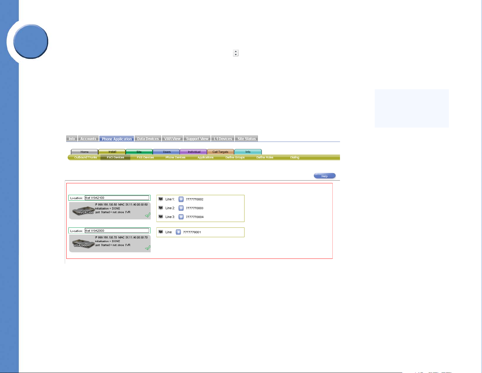
Configuring FXO Devices
The FXO Devices screen allows you to see the status of the FXO devices, such as voice
gateways, that are connected to your Services Router. This screen also allows you to specify
a label for each FXO device and assign trunks to ports.
Chapter 6: Using the Phone Application
Setting Install Time Configuration
17
Page 24
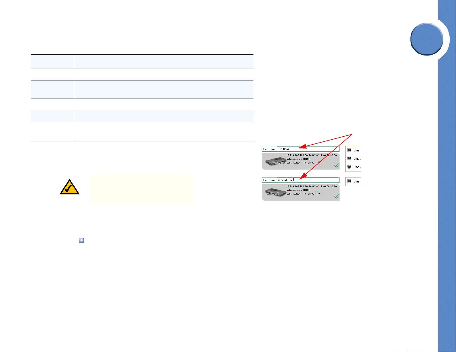
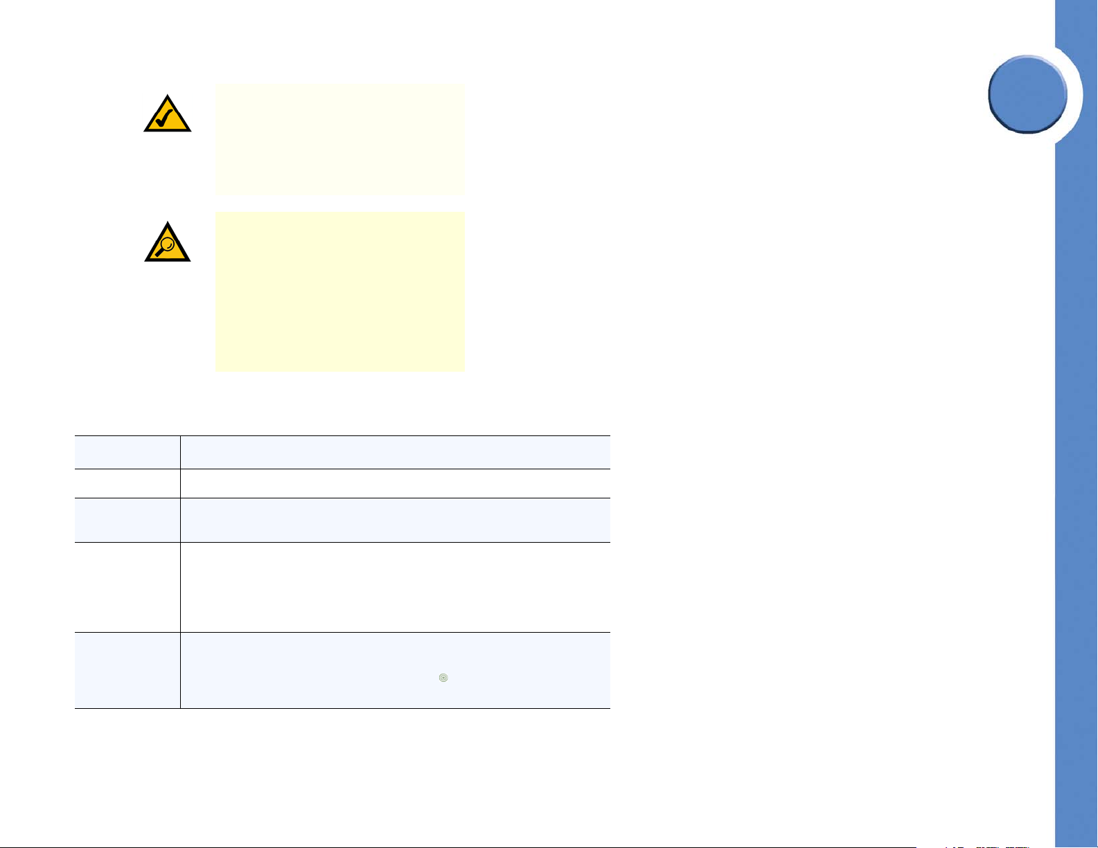
Refer to the following table for a description of the information displayed in the FXO Devices
FXO Device Location Fields
screen.
Linksys One Communications Solution
6
Field Description
IP The Internet Protocol (IP) address of the device.
MAC The Media Access Control (MAC) address is the unique identifier for the device.
This number is also printed on the device.
Initialization The status of the initialization process.
Last Started The time since the system was last started.
Line The port label as indicated on the physical port of the device. For each
available port, a label is displayed next to the RJ-11 icon.
To add a Location to an FXO Device:
1. Type location text in the Location field.
NOTE: The Location field is a descriptive
label only and is not used any where
else in the Linksys One system.
2. Click Commit.
Chapter
To assign a trunk to the port of a Device:
1. Click the more ( ) and choose a trunk.
2. If necessary, repeat step 1 for all other ports.
3. Click Commit.
18
Chapter 6: Using the Phone Application
Setting Install Time Configuration
Page 25
Linksys One Communications Solution
An FXS device (Foreign
Exchange Station) or port on
an FXS device, allows an
analog telephony device,
such as a phone handset or
fax machine to be connected.
The FXS device provides dial
tone and ring voltage to the
analog telephony device.
6
Chapter
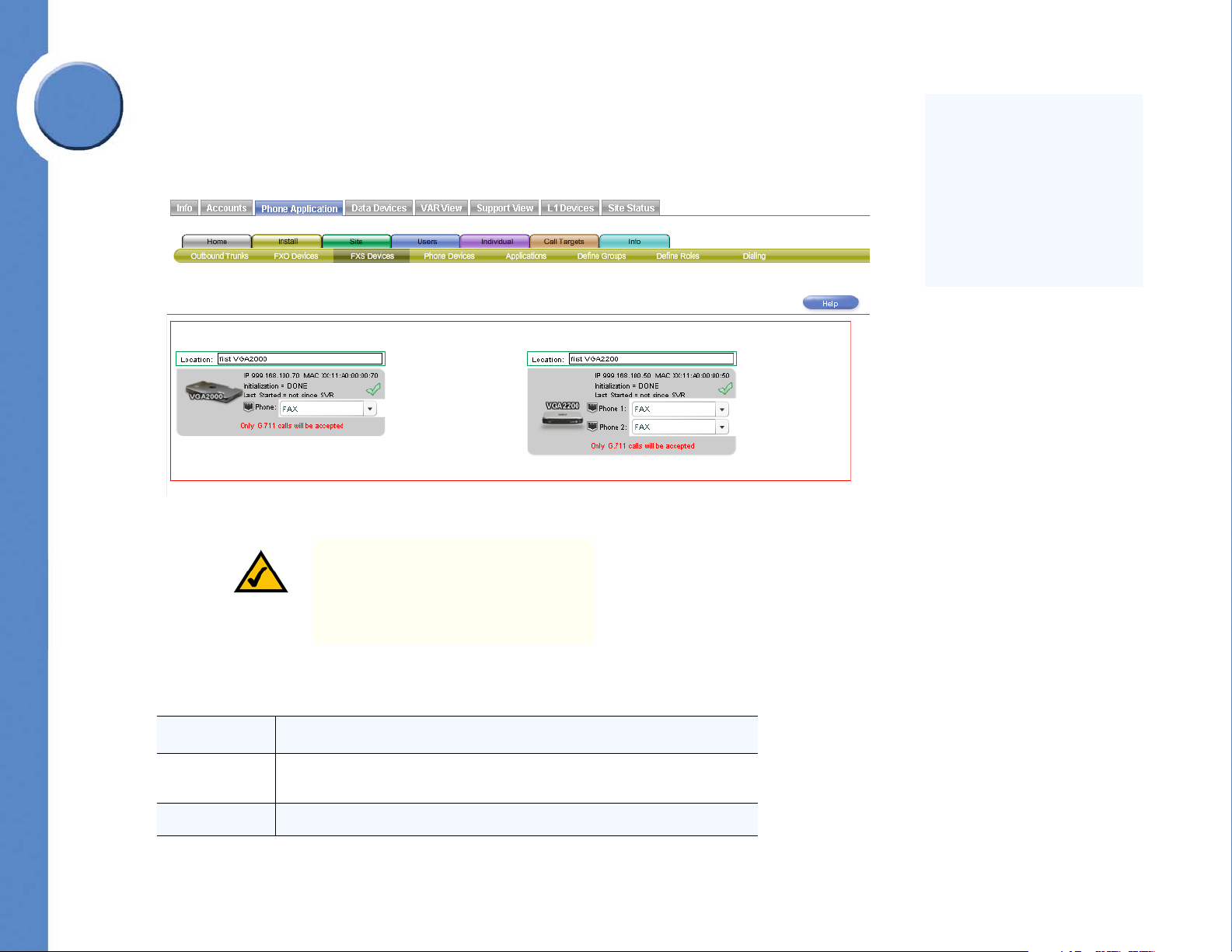
Configuring FXS Devices
The FXS Devices screen allows you to see the status of the FXS devices connected to your
Services Router. You can also assign the port usage of each port on the FXS device.
NOTE: When a port is set to FAX, the
VGA will only accept G.711 calls; even
if only one port is set to FAX. G.711 is
the international standard for encoding
audio on a 64 kbps channel.
Refer to the following table for a description of the information displayed in the FXS Devices
screen.
Field Description
Location The physical location of the FXS device. This is only a text label used to specify
IP The Internet Protocol (IP) address of the device.
Chapter 6: Using the Phone Application
Setting Install Time Configuration
its location.
19
Page 26
Linksys One Communications Solution
Field Description
MAC The Media Access Control (MAC) address is the unique identifier for the device.
This number is also printed on the device.
Initialization The status of the initialization process.
Last Started The time since the FXS device was last started.
To assign the port usage of an FXS port:
1. Click the FXS device port drop down button ( ) on the port that you want to change.
2. Select a port usage of the port.
3. Click Commit.
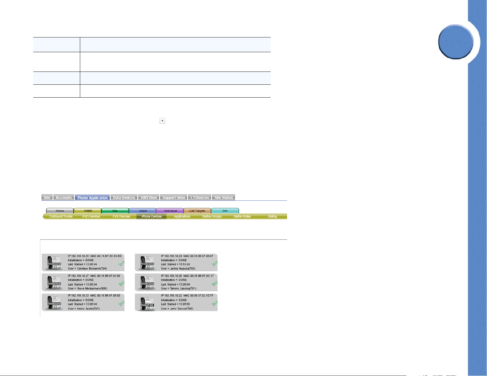
Viewing Phone Devices
The Phone Devices screen allows you to see the status of the user’s phones.
6
Chapter
20
Chapter 6: Using the Phone Application
Setting Install Time Configuration
Page 27
6
Linksys One Communications Solution
Phones that are not registered with the Services Router appear with red text in the IP/MAC
line. You can delete a removed, or defective, phone from this screen by clicking the options
( ) button and selecting Delete.
Refer to the following table for a description of the information displayed in the Phone
Devices screen.
Chapter
Field Description
IP The Internet Protocol (IP) address of the device.
MAC The Media Access Control (MAC) address is the unique identifier for the device.
This number is also printed on the device.
Initialization The status of the initialization process.
Last Started The time since the system was last started.
User The name and extension of the user assigned to the phone.
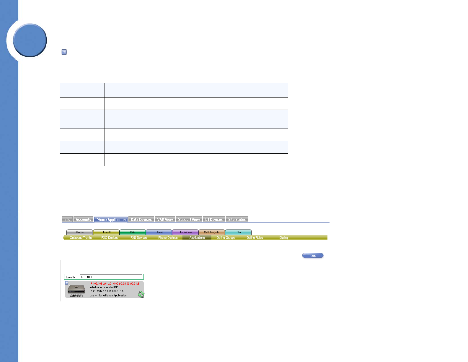
Viewing Application Device Status
The Applications screen allows you to see the status of your application device and the
application that is currently loaded.
Chapter 6: Using the Phone Application
Setting Install Time Configuration
21
Page 28

Refer to the following table for a description of the information displayed in the Applications
Devices screen.
Linksys One Communications Solution
6
Field Description
Location The physical location of the application device. This is only a text label used to
specify its location.
IP The Internet Protocol (IP) address of the device.
MAC The Media Access Control (MAC) address is the unique identifier for the device.
This number is also printed on the device.
Initialization The status of the initialization process.
Last Started The time since the system was last started.
Use The name of the application loaded on the application device.
To assign a location label to an Application Device:
1. Type label text in the location field.
2. Click Commit.
Chapter
22
Chapter 6: Using the Phone Application
Setting Install Time Configuration
Page 29
Linksys One Communications Solution
A Group is an extension that
is created for the purpose of
sharing calls among devices.
An incoming call rings
simultaneously on all devices
in the group. All devices show
the call state.
6
Chapter
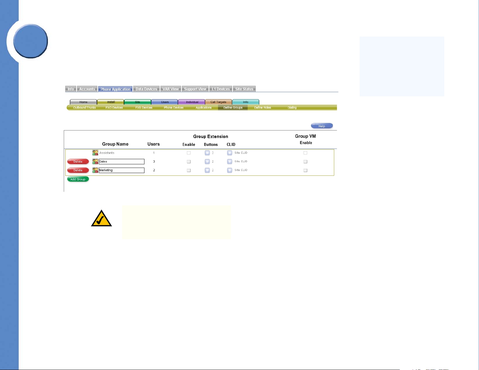
Defining Groups
The Define Groups screen allows you to create or modify groups into which you can place
users. For example, you may categorize your users into groups such as “Sales” or
“Support.” Changes to this screen require a system restart before they take effect.
NOTE: The Assistants group is included
by default and cannot be deleted.
Assistants are assigned to users in the
Users > Assistants screen.
Users are assigned to groups in the Users > Group Assignments screen.
Chapter 6: Using the Phone Application
Setting Install Time Configuration
23
Page 30
Refer to the following table for a description of the information displayed in the Define
CLID is a telephony service that
transmits the caller’s telephone number
and in some places the caller's name to
the called party’s telephone equipment
during the ringing signal or when the
call is being set up but before the call is
answered.
Groups screen.
Linksys One Communications Solution
6
Field Description
Group Name Name assigned to the group. The group name assigned here also appears on
the following screens:
• Users > Group Assignments
• Call Targets > Groups
• Call Targets > Voicemail Boxes (if “Group VM Enable” is checked)
• Call Targets > Inbound Trunks (if “Group Extension Enable” is
checked)
• Call Targets > Call Forwards (if “Group Extension Enable” is checked)
• Individual > User Template (if “Group Extension Enable” is checked
and the user is assigned in the Users > Group Assignments screen)
• Info (if a trunk is assigned to the group)
Users Number of users assigned to this group as specified in the Users > Group
Assignments screen.
Group Extension Allows you to enable group extensions, assign number of buttons, and choose
a Calling Line Identification (CLID) for the group.
Enable Enables or disables this group extension. When enabled, the group name also
appears on the Individual > User Template screen for a user assigned to the
group. Note: Even if a group extension is not enabled on this screen, the group
will still appear on the Users > Group Assignments screen; however, the group
extension must be enabled to assign the group button on the user’s phone. Even
though a group may be disabled, it still can be used as a filter for displaying
users with the Filter Users pulldown.
Chapter
Buttons The number of buttons allocated to each user’s phone for this group.
CLID The CLID displayed on calls from this group. Note: For customers using local
trunks only, this field is not available.
Group VM
Enable
Enables or disables a voicemail box for this group. Note: For external
voicemail, a trunk must be assigned to the group in the Call Targets > Inbound
Trunks screen.
24
Chapter 6: Using the Phone Application
Setting Install Time Configuration
Page 31

6
Linksys One Communications Solution
To create a new group:
1. Click Add Group.
2. Type a name for the group in the Group Name area.
3. Click Commit.
Chapter
To delete a group:
1. Click the Delete button next to the group you want to delete.
2. Click Commit.
To enable and configure a Group Extension:
1. In the Group Extension area, click the Enable checkbox ( ).
2. Click the more button ( ) and select the number of buttons to allocate to each user's
phone for this group.
3. Click the more button ( ) and choose a CLID for this group.
4. Click Commit.
To enable a voicemail box for a group:
1. In the Group VM area, click a checkbox for the appropriate group.
2. Click Commit.
Chapter 6: Using the Phone Application
Setting Install Time Configuration
25
Page 32

Linksys One Communications Solution
A role is an extension that is
created for the purpose of
rolling an unanswered call to
other devices in a predetermined order.
Defining Roles
The Define Roles screen allows you to create or modify roles into which you can place users.
For example, you may categorize your users into a role such as “Operators.” Changes to
this screen require a system restart before they take effect.
NOTE: The Operator role is included by
default and cannot be deleted.
6
Chapter
Users are assigned to roles in the Users > Role Assignments screen.
26
Chapter 6: Using the Phone Application
Setting Install Time Configuration
Page 33

6
Chapter
Linksys One Communications Solution
Refer to the following table for a description of the information displayed in the Define Roles
screen.
Field Description
Role Name Name assigned to the role. The role name assigned here also appears on the
following screens:
• Users > Role Assignments
• Call Targets > Roles
• Call Targets > Voicemail Boxes (if “Role VM Enable” is checked)
• Call Targets > Inbound Trunks (if “Role Extension Enable” is checked)
• Call Targets > Call Forwards (if “Role Extension Enable” is checked)
• Individual > User Template (if “Role Extension Enable” is checked and
the user is assigned in the Users > Role Assignments screen)
• Info (if a trunk is assigned to the role)
Users Number of users assigned to this role as specified in the Users > Role
Assignments screen.
Role Extension Allows you to enable role extensions, assign number of buttons, and choose a
Calling Line Identification (CLID) for the role.
Enable Enables or disables the role’s extension. When enabled, the role name also
appears on the Individual > User Template screen for a user assigned to the
role. Note: Even if a role extension is not enabled on this screen, the role will
still appear on the Users > Role Assignments screen; however, the role
extension must be enabled to assign the role button to the user’s phone. Even
though a role may be disabled, it still can be used as a filter for displaying
users with the Filter Users pulldown.
Buttons The number of buttons allocated to each user's phone for this role.
CLID The CLID displayed on calls from this role. Note: For customers using local
trunks, this field is not available.
Role VM Enable Enables or disables a voicemail box for this role. Note: For external voicemail,
a trunk must be assigned to the role in the Call Targets > Inbound Trunks
screen.
Chapter 6: Using the Phone Application
Setting Install Time Configuration
27
Page 34

To crea te a n ew ro le :
1. Click Add Role.
2. Type a name for the group in the Role Name area.
3. Click Commit.
To delete a role:
1. Click the Delete button next to the role you want to delete.
2. Click Commit.
To enable and configure a role:
1. In the Role Extension area, click the Enable checkbox ( ).
2. Click the more button ( ) and select the number of buttons to allocate to each user's
phone for this role.
3. Click the more button ( ) and choose a CLID for this role.
4. Click Commit.
Linksys One Communications Solution
6
Chapter
To enable a voicemail box for a role:
1. In the Role VM area, click a checkbox for the appropriate role.
2. Click Commit.
28
Chapter 6: Using the Phone Application
Setting Install Time Configuration
Page 35

Linksys One Communications Solution
6
Chapter
Defining Dialing Patterns
The Dialing screen allows you to specify a default Calling Line Identification (CLID) for the
site, enable Auto Attendant after hours forwarding, and assign steering digits.
Chapter 6: Using the Phone Application
Setting Install Time Configuration
29
Page 36
Linksys One Communications Solution
NOTE: The site CLID is over-ridden if a
different CLID is assigned to a role in the
Install > Define Roles screen, if a group
in the Install > Define Groups screen, or
if Private CLID is enabled for the user in
the Users > Permissions screen.
TIP: Normally, Site CLID cannot be
assigned to a user’s extension. However,
you can assign a CLID to a user if you
unassign the extension from the user in
the Users > Inbound Trunks screen,
assign the extension as Site CLID in the
Install > Dialing screen, then reassign
that extension back to the user in the
Users > Inbound Trunks screen.
Refer to the following table for a description of the information displayed in the Dialing
screen.
Field Description
Site CLID Label CLID label for the site.
6
Chapter
Site CLID CLID assigned to this site. Note: For customers using local trunks, this field is not
available.
Auto Attendant
After Hours
Forwarding
Steering Digit Prefix digits for accessing functions. For example, if the function “IP Trunk” is
30
Enables calls to AA to be concurrently directed to another number; both the AA
and additional number phone ring at the same time. This feature is useful if you
want an after-hours service to answer calls that have been directed to the afterhours Auto Attendant. The number is assigned in Site > Settings (Auto
Attendant After Hours Forwarding Transfer Number field).
assigned to steering digit 9, then the user must press 9 to access an IP trunk. A
steering digit with a circular target drop target ( ) means that a function has
not been assigned to that steering digit.
Chapter 6: Using the Phone Application
Setting Install Time Configuration
Page 37
Linksys One Communications Solution
6
Chapter
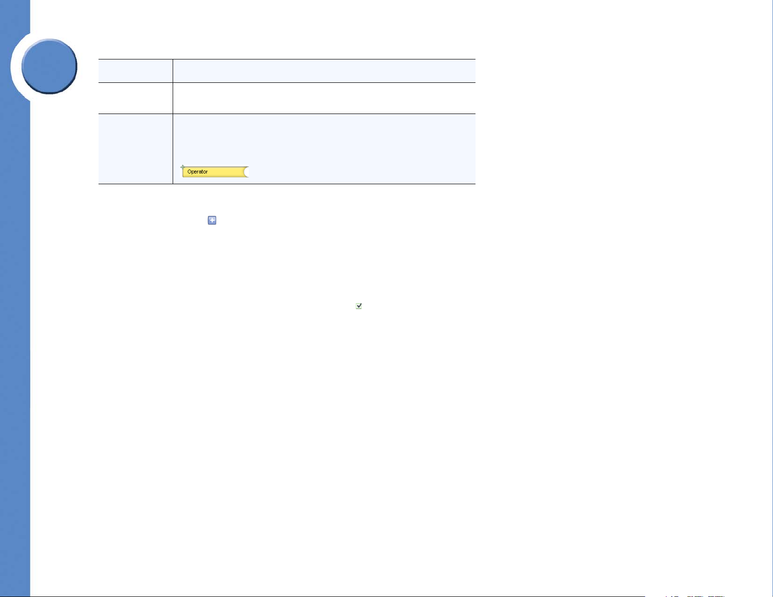
Field Description
Pattern Dialing pattern for each Steering digit. Each “X” in this column can be any
valid digit.
Function Name of the action, or function, that is assigned to a steering digit. Note: The
function objects are shown in two different sizes: short and long. The long
objects cannot be assigned to digit 0, but the short objects can be assigned to
any digits including 0. Here is an example of the (short) Operator function:
.
To change the site CLID:
1. Click the more button ( ) to see a list of available numbers.
2. Select one of the available numbers to be used for calling line identification.
3. Click Commit.
To enable the Auto Attendant External Night Service:
1. Click the Auto Attendant External Night Service checkbox ( ).
2. Click Commit.
Chapter 6: Using the Phone Application
Setting Install Time Configuration
31
Page 38

To change the assignment of a function to a different steering digit:
1. Locate a function that you want to assign to another steering digit.
2. For each function that you want to assign, drag its move icon ( ) to the circular target
( ) for the new steering digit.
NOTE: If a steering digit already
contains a function, drag its move icon
( ) anywhere on the target area and the
new function replaces the existing
function. The existing function is moved
to the location of the new function (they
are swapped).
3. Click Commit.
Configuring Site Settings
Site settings affect the overall customer’s site. They include things like defining a system
maintenance window and selecting the music to play to callers on hold. Here you can also
document comments about the site. Site settings are configurable from the Site tab in the
Phone Application.
Linksys One Communications Solution
6
Chapter
32
Chapter 6: Using the Phone Application
Configuring Site Settings
Page 39

Linksys One Communications Solution
6
Chapter
Setting Site Options
The Settings screen allows you to change the Music on Hold, change the time that the
Maintenance window occurs, assign an after-hours Auto Attendant (AA) forwarding
number, and enter comments about the site.
Chapter 6: Using the Phone Application
Configuring Site Settings
33
Page 40

Refer to the following table for a description of the information displayed in the Site screen.
Linksys One Communications Solution
6
Field Description
Select music on
hold for external
lines
Maintenance
Window
Select the music that outside callers hear when they are placed on hold. The
change will affect any subsequent calls placed on hold.
Once a day, the Services Router checks for changes that are waiting to be
made to the phone system. This includes changes committed through the Phone
Application as well as any service or software changes from the Service Node.
You can define a two-hour window for the maintenance to occur, but by default,
the two-hour maintenance window occurs randomly between 12 AM and 5
AM. Maintenance can take approximately 30 minutes and can cause the
system to become unavailable to users; choose a time when the system is not
normally in use. Changes in this screen are applied immediately without
restarting any hardware when you click Commit.
During system maintenance, the Services Router:
• Writes the current database to the USB key (SVR3000 only).
• Attempts (once) to back up the current database to the Service Node.
• Reboots if there are pending changes made by the Linksys One Portal
that need to be distributed to system.
• Attempts (once) to read provisioning data from the Service Node. If
the attempt is successful and if there are changes in either the target
software version or in the provisioning data itself, then the Services
Router reboots and causes the changes to take effect.
Chapter
Phone Desktop If a phone desktop is not assigned on the Service Node, then this option allows
you to choose a different desktop for the phones in the system.
34
Chapter 6: Using the Phone Application
Configuring Site Settings
Page 41

Linksys One Communications Solution
6
Chapter
Field Description
Auto Attendant
After Hours
Forwarding
Transfer Number
Site Comments You can enter text in the Site Comments area that pertain to this site. For
To select music for external lines on hold:
1. Click the drop down button ( ) in the Select music on hold for external lines area.
2. Select one of the available music titles.
3. Click Commit.
To change the maintenance window:
The Auto Attendant After Hours Forwarding Transfer Number area allows you
to assign an after-hours AA forwarding number. An after hours call is
forwarded to both this number and to the operator. If no number is entered in
this field, the call is forwarded to the operator.
Note: the Auto Attendant After Hours Forwarding option in the Install >
Dialing screen must be checked for this option to be available.
Note: A steering digit must precede the AA Forwarding number. For example,
if the AA Forwarding number is 214-555-1212 and the steering digit for an IP
Trunk is 9, then the number to enter would be 9-214-555-1212.
example, you could put site contact information in this area.
1. Click the down arrow ( ) in the Maintenance Window area.
2. Select one of the available maintenance windows.
3. Click Commit.
To change the phone desktop:
1. Click the down arrow ( ) in the Phone Desktop area.
2. Select one of the available desktop choices.
3. Click Commit.
Chapter 6: Using the Phone Application
Configuring Site Settings
35
Page 42

To assign an after-hours AA forwarding number:
1. Ensure that the Auto Attendant After Hours Forwarding option is checked ( ) in the
Install > Dialing screen.
2. Enter a valid phone number in the Auto Attendant After Hours Forwarding Transfer
Number area.
NOTE: A steering digit must precede the
AA Forwarding number. For example, if
the AA Forwarding number is 214555-1212 and the steering digit for an
IP Trunk is 9, then the number to enter
would be 9-214-555-1212.
3. Click Commit.
To enter site comments:
1. Put the cursor in the Site Comments text box.
2. Enter any comments that you want about this site.
Linksys One Communications Solution
6
Chapter
3. Click Commit.
Defining Auto Attendant Hours
The Auto Attendant Hours screen allows you to define the times that the Auto Attendant
answers calls and plays the main greeting. You can specify up to five different day types. For
example, for the day type “Regular” you can customize the Auto Attendant to play the main
greeting from 8:00 AM to 6:00 PM.
36
Chapter 6: Using the Phone Application
Configuring Site Settings
Page 43

6
Chapter
Linksys One Communications Solution
Check the boxes for the times that you want the Auto Attendant to answer calls with the main
greeting. If you leave a box unchecked, the Auto Attendant plays the closed greeting for that
time interval.
In this screen, you can also customize labels for the type of days. The labels you enter here
appear in the Site > Auto Attendant Days screen.
Chapter 6: Using the Phone Application
Configuring Site Settings
37
Page 44

To customize type of days labels:
1. Type a new label in the label area.
2. Click Commit.
After configuring hours for each type of day, configure the days to use them on the Auto
Attendant Days screen.
To set Auto Attendant hours:
1. Check the boxes for the times that you want the Auto Attendant to answer calls with the
main greeting. If you leave a box unchecked, the Auto Attendant plays the closed
greeting for that time interval.
2. (Optional) Change the labels for the type of days by clicking in the label box and typing
a new label. For example, you can change the day type labeled “Short“ to “Mornings.”
3. Click Commit.
Defining Auto Attendant Days
The Auto Attendant Days screen allows you to define how the Auto Attendant answers calls
on each day of the week. For example, you can define Monday as a “regular” day and
Saturday as a “closed” day. Here you can also add custom dates and associate a specific
day type. For example, you could create January 1, 2008 as a “closed” day.
Linksys One Communications Solution
6
Chapter
38
Chapter 6: Using the Phone Application
Configuring Site Settings
Page 45

6
Chapter
Linksys One Communications Solution
You configure the specific hours for “regular” and “closed” and other day types on the Site >
Auto Attendant Hours screen.
Refer to the following table for a description of the information displayed in the Auto
Attendant Days screen.
Field Description
Days of the
Week and Day
Type
Chapter 6: Using the Phone Application
Configuring Site Settings
This vertical column lists the days of the week (Monday through Sunday) and
the custom days. You can add more custom dates to this column.
The column headings are defined on the Site > Auto Attendant Hours screen.
39
Page 46

Linksys One Communications Solution
Field Description
Add Day This button allows you to add a custom day (a holiday for example) to the
schedule.
Delete This button enables you to delete a custom date that you have added. If you
have not added any custom dates, this button is not visible.
To add a day:
1. Click Add Day. A new day appears in the list.
2. Click the Calendar button ( ) and select a date.
3. For each date you add, select the day type (for example, Closed, Regular, Short, Long or
Other).
4. Click Commit.
To set Auto Attendant days:
1. For each day of the week, select the type of day. Each day can be assigned to only one
day type.
2. Click Commit.
6
Chapter
Configuring Email
The Linksys One solution uses email for voicemail delivery and CPE alerts. However, some
outgoing Simple Mail Transfer Protocol (SMTP) email servers require that mail clients login to
a server before they will accept outgoing email. Some servers block port 25 for email
sending, some use domain name resolution (MX record) to validate originator’s IP address,
or other servers may require a secure TLS/SSL connection. It is for these reasons that the
40
Chapter 6: Using the Phone Application
Configuring Site Settings
Page 47

6
Chapter
Linksys One Communications Solution
Email Config screen allows you to specify email options which enable the delivery of email
through servers that might otherwise block email service from your Linksys One system.
Chapter 6: Using the Phone Application
Configuring Site Settings
41
Page 48

After you have configured an email account, you can send a test message to ensure that the
email settings are correct.
Linksys One Communications Solution
6
Field Description
Use Email
Account On
Host Name Name of the email server.
SMTP Port
Number
Require SSL To
Connect
Use Account
Login
Account
Username
Account
Password
Email 'From'
Address
Type of email account to use. Note: The options below this field vary depending
on the type of account chosen; possible options are described below.
SMTP server port number. The default port value is 25.
Checkbox to specify if the email server requires the Secure Socket Layer (SSL)
protocol.
Checkbox to specify if an account username and login is required.
Username of the email account. This field can be edited if the “Use Account
Login” checkbox is selected.
Password of the email account. This field can be edited if the “Use Account
Login” checkbox is selected.
Email address shown in the "from" field of the received email.
To select an email account:
Chapter
1. Click the down arrow ( ) in the “Use Email Account On” area.
2. Select an email account to use.
3. Fill out the fields that apply to the type of email account chosen.
4. Click Commit.
42
Chapter 6: Using the Phone Application
Configuring Site Settings
Page 49
6
With the Filter Users feature
you can view users by name,
extension type, device type,
group, or role. Click the filter
button ( ) to select a filter.
Linksys One Communications Solution
To send a test email:
1. Enter a valid email in the box next to the Send Test Email To button.
2. Click S end Tes t Em ail To.
Managing Users
Chapter
The screens in the Users tab allow you configure numerous settings for the users of your
system. You can add, delete, and change names; configure user’s roles and groups;
authorize phone usage features (permissions), assign assistants, DIDs, trunks, extensions,
and devices. You can also configure SNR (Single Number Reach) settings.
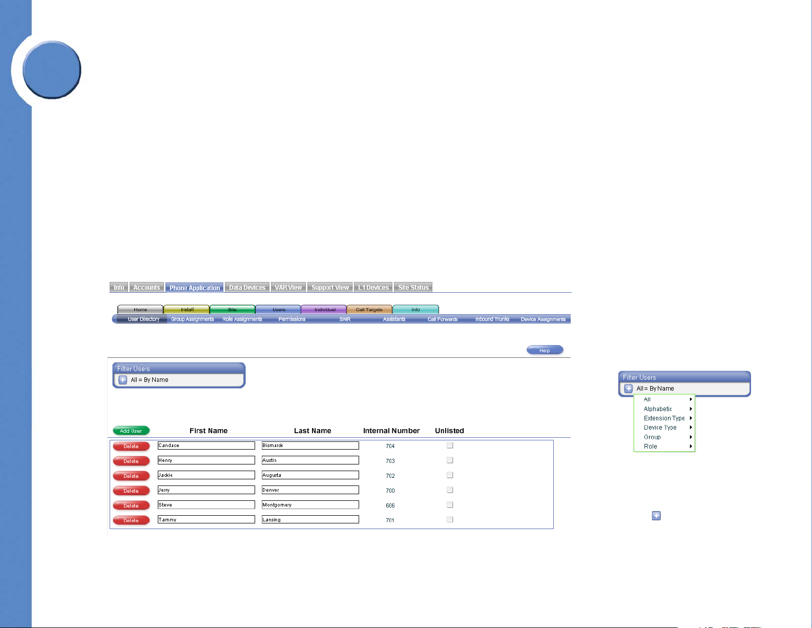
Assigning Names to Users
The User Directory screen allows you to assign a name with an extension. Changes on this
screen may require a restart of the affected phones.
Chapter 6: Using the Phone Application
Managing Users
43
Page 50

Refer to the following table for a description of the information displayed in the User
Directory screen.
Linksys One Communications Solution
6
Field Description
First Name and
Last Name
Internal Number The inbound trunk number assigned to the user. Inbound trunk numbers cannot
Unlisted Prevents a user's first and last name from appearing in the Auto Attendant
To add a user:
1. Click Add User.
2. Add a first and last name for the user.
3. Click Commit.
To delete a user:
The name of the user that is associated with an extension and used in the Auto
Attendant’s directory (for a user to be in the Auto Attendant directory, they
should have their name recorded in the voice recording), Local Directory on the
users’s phone screen, and that appears as the caller ID for internal calls. Both
name fields cannot be left blank, a name must be entered in at least the First
Name or Last Name field.
be changed on this screen, refer to the Users > Inbound Trunks screen for
inbound trunk definition.
directory and the Local Directory on the phone.
Chapter
1. Click Delete in the row of the user to delete.
2. Click Commit.
To change a user’s name:
1. Add or change the first and last name of the user.
2. Click Commit.
44
Chapter 6: Using the Phone Application
Managing Users
Page 51
6
With the Filter Users feature
you can view users by name,
extension type, device type,
group, or role. Click the filter
button ( ) to select a filter.
Linksys One Communications Solution
To unlist a number from the AA and phone directories:
1. Click the Unlisted checkbox. A check ( ) appears in the checkbox.
2. Click Commit.
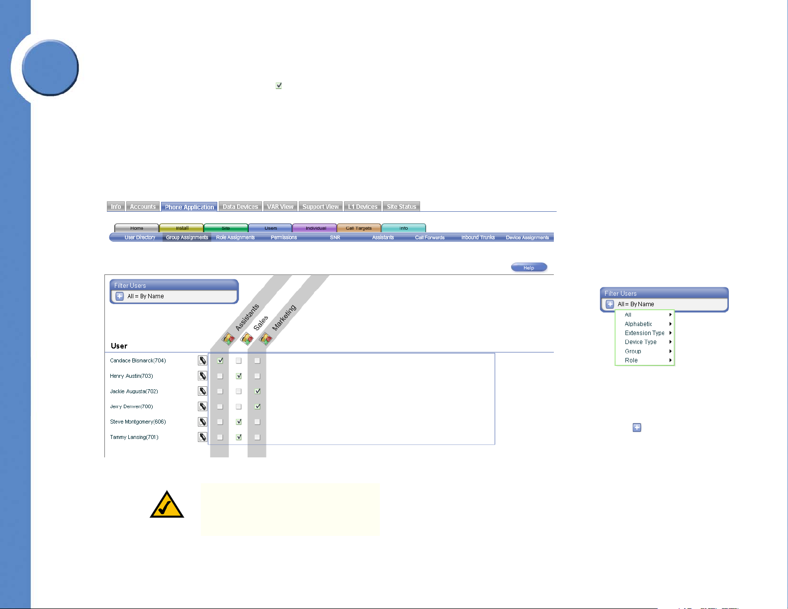
Assigning Users to Groups
Chapter
The Group Assignments screen allows you to assign a user to a group; a user can be
assigned to multiple groups. Groups are defined and enabled in the Install > Define Groups
screen.
Chapter 6: Using the Phone Application
Managing Users
NOTE: FXS devices cannot be assigned
to a group; this is indicated by a “Not
Allowed” banner.
45
Page 52

To assign a user to a group:
1. Click a checkbox ( ) in each group that you want the user to belong.
2. Click Commit.
NOTE: Group buttons are automatically
assigned to available consecutive
buttons on the user’s phone. If button
space is not available on the user's
phone, the user template must be
adjusted using the Individual > User
Temp la te s screen.
NOTE: Buttons are only assigned if
enabled for the group in the Install >
Define Groups screen.
Assigning Users to Roles
Linksys One Communications Solution
6
Chapter
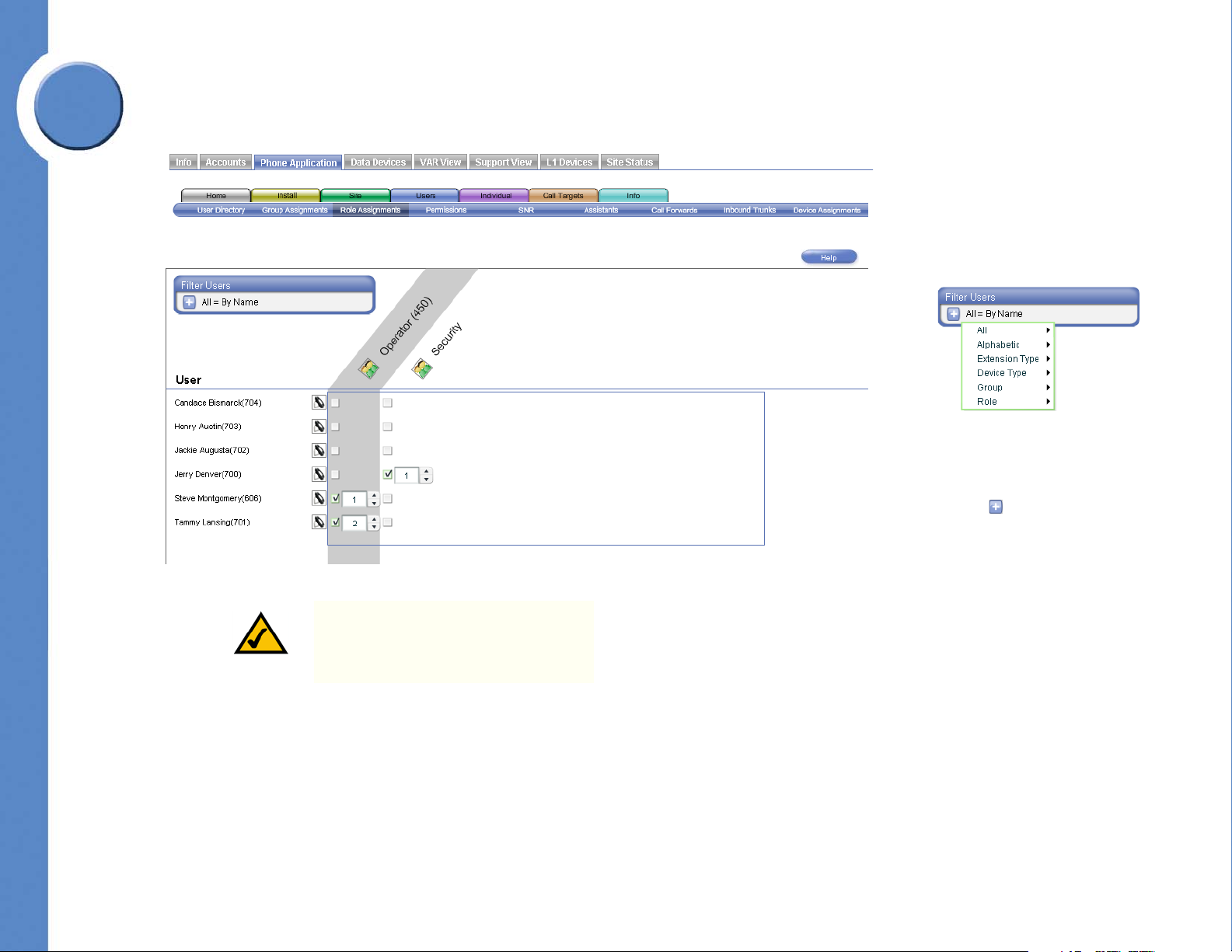
The Role Assignments screen allows you to assign a role to a user and assign the priority in
which the user's phones will ring in the role. For example, if Sam, Joe, and Terry are
assigned as operators, with the priority of 1, 2, and 3 respectively, and someone calls an
46
Chapter 6: Using the Phone Application
Managing Users
Page 53
6
With the Filter Users feature
you can view users by name,
extension type, device type,
group, or role. Click the filter
button ( ) to select a filter.
Chapter
Linksys One Communications Solution
operator, then Sam's phone will ring first. If Sam does not answer the call, then Joe's phone
will ring; if Joe does not answer the call, then Terry's phone will ring.
Roles are defined in the Install > Define Roles screen.
Chapter 6: Using the Phone Application
Managing Users
NOTE: FXS devices cannot be assigned
to a role; this is indicated by a “Not
Allowed” banner.
47
Page 54
To assign a role and priority level to a user:
1. Click a checkbox ( ) corresponding to the user in a role. A priority box opens for the
user and a priority value is automatically assigned to the user.
2. If necessary, assign a priority to the user by clicking on the up-down button ( ), or by
entering a numeric value in the priority box. As priority values are changed for one user,
the priority values of other users in the role automatically change.
3. Click Commit.
NOTE: Role buttons are automatically
assigned to available consecutive
buttons on the user’s phone. If button
space is not available on the user's
phone, the user template must be
adjusted using the Individual > User
Temp la te s screen.
NOTE: Buttons are only assigned if
enabled for the group in the Install >
Define Roles screen.
Linksys One Communications Solution
6
Chapter
48
Chapter 6: Using the Phone Application
Managing Users
Page 55

Linksys One Communications Solution
With the Filter Users feature
you can view users by name,
extension type, device type,
group, or role. Click the filter
button ( ) to select a filter.
6
Chapter
Assigning Permissions to Users
The Permissions screen allows you to enable or disable features and to specify feature access
and classes of service for a user. Classes of service allow, or restrict, access to specific
network services such as long distance, premium content, and international numbers.
These are some examples of services that might be part of a dial plan:
• Long Distance—enables or disables long distance calling for this user.
• International—enables or disables international calling for this user.
• Premium Srvc—enables or disables premium services for this user.
• Directory Srvc—enables or disables directory services for this user.
Optional services vary, depending on how the site accounts are set up on the Service Node.
Chapter 6: Using the Phone Application
Managing Users
49
Page 56

Refer to the following table for a description of the information displayed in the Permissions
screen.
Linksys One Communications Solution
6
Field Description
User Name of the user as defined in the User Directory.
Has DID Indicates whether or not this user's phone number is a DID number (Y for yes,
and N for no).
Rules for Permissions
The following rules apply to the permissions specified in this screen.
Personal Voicemail (applies to DID and non-DID numbers)
• If using external voicemail, the Personal voicemail permission checkbox is disabled
and cleared for a user with an internal only extension.
SNR
There is a limit of 25 users who can be concurrently assigned the SNR feature.
If the user is assigned an FXS phone:
• The “Private CLID” box is cleared and disabled for non-DID users.
• The Personal VM and Mobility Feature privilege checkboxes are hidden and
replaced with an “N.”
Chapter
• All dial plan specific features, such as long distance, are always allowed; specified
by an “Allowed” banner.
Private CLID
If user does NOT have DID assigned:
• The Private CLID permission checkbox is disabled and cleared.
• For all other users, the Private CLID can be enabled or disabled by selecting or
unselecting the Private CLID checkbox.
50
Chapter 6: Using the Phone Application
Managing Users
Page 57

6
Chapter
Linksys One Communications Solution
Auto-Answer Pages
One-to-one paging can be enabled or disabled by selecting or unselecting the Auto-Answer
Pages checkbox.
Allow Offsite Calls
Allows offsite calling when “Allow Offsite Calls” checkbox is selected.
NOTE: Users who are assigned an FXS
phone are not allowed to forward calls
offsite.
If user does NOT have “Allow Offsite Calls” permission (checkbox disabled):
• The SNR permission checkbox is disabled and cleared.
• The “Private CLID” box is hidden and not replaced with anything.
• The “Forward Offsite” permission checkbox is disabled and cleared.
• Dial Plan flags are hidden and services are disabled for the user.
To specify a feature or class of service for a user:
1. For each user, click a checkbox ( ) corresponding to the service you want the user to
access.
2. Click Commit.
3. The system will prompt you to restart the phone for which the service was enabled. Click
Changes Pending and then Restart Phone.
Assigning SNR to Users
The SNR (Single Number Reach) screen allows you to specify a number that rings
concurrently with the user’s number. For example, if SNR is directed to a user’s cell phone,
Chapter 6: Using the Phone Application
Managing Users
51
Page 58

then his or her cell phone will ring at the same time that someone calls the user's number.
With the Filter Users feature
you can view users by name,
extension type, device type,
group, or role. Click the filter
button ( ) to select a filter.
The incoming call is routed to the phone that answers first.
Linksys One Communications Solution
6
Chapter
52
NOTE: FXS devices cannot be
authorized for SNR; this is indicated by
a “Not Allowed” banner.
Chapter 6: Using the Phone Application
Managing Users
Page 59

6
Chapter
Linksys One Communications Solution
Refer to the following table for a description of the information displayed in the SNR screen.
Field Description
User Name and extension of the user as defined in the User Directory.
Authorize Allows this user to access the SNR feature. If this option is unchecked, then the
Enable and Target fields are disabled, and any existing number is cleared. If
the Authorize option is disabled, the user will not see the SNR feature in the
Individual > User Settings screen. When the Authorized option is enabled, the
Enable checkbox becomes selectable and a Target destination can be entered.
The Authorize checkbox is mirrored in the Users > Permissions screen (SNR
column).
Enable Enables SNR for this user. This checkbox is mirrored on the Individual > User
Setting screen for this user and the Tasks > Call Forwarding / SNR setting on
the phone. A target for the call must be specified as defined below.
Tar ge t A multisite or external phone number for the SNR destination. This SNR number
is mirrored on the Individual > User Setting screen for this user. Note: Enter a
number just as you would dial it from your phone. For example, if the SNR
phone number is 214-555-1212 and you normally dial 9 to access an IP Trunk,
then the number to enter into the Target field would be
9-214-555-1212.
To authorize SNR for a user:
1. For each user, click the Authorize checkbox ( ). The Enable checkbox becomes
accessible and this user will see the SNR feature in their Individual > User Settings
screen.
2. Click Commit.
Chapter 6: Using the Phone Application
Managing Users
53
Page 60

To enable SNR for a user:
1. For each user, click an Enable checkbox ( ).
2. Enter an appropriate steering digit and SNR number.
3. Click Commit.
NOTE: SNR and Mobility buttons are
automatically assigned to vacant
buttons on the user's phone. If the
buttons are not available on the user's
phone, the user template must be
adjusted using the Individual > User
Temp la te s screen.
NOTE: The SNR button lights green on
the user’s phone if it has been allocated
in the user’s template.
Linksys One Communications Solution
6
Chapter
54
Chapter 6: Using the Phone Application
Managing Users
Page 61

Linksys One Communications Solution
With the Filter Users feature
you can view users by name,
extension type, device type,
group, or role. Click the filter
button ( ) to select a filter.
6
Chapter
Assigning Assistants to Users
The Assistants screen allows you to assign an assistant to a user. When assistants are
assigned to users, three personal extension buttons and the mailbox button for each
associated user become available on the assistant’s phone (if buttons are available).
Before assistants can be assigned to users, they must first be defined as assistants in the
Users > Group Assignments screen. While the Linksys One Portal does not limit the number
of users each assistant can support, there is a practical limit due to the number of buttons on
the assistant’s phone.
Chapter 6: Using the Phone Application
Managing Users
55
Page 62
Refer to the following table for a description of the information displayed in the Assistants
screen.
Linksys One Communications Solution
6
Field Description
User Name and extension of the user as defined in the User Directory.
Assistant Name of the assistant assigned to the user.
To assign an assistant to a user:
1. For each user, click the more button ( ). A list of available assistants appear.
2. Select an available assistant.
3. Click Commit.
Chapter
56
Chapter 6: Using the Phone Application
Managing Users
Page 63

Linksys One Communications Solution
With the Filter Users feature
you can view users by name,
extension type, device type,
group, or role. Click the filter
button ( ) to select a filter.
6
Chapter
Forwarding Calls
The Call Forwards screen allows you to specify call forward options for users. You can also
change the number of rings that occur before the call is forwarded. For “Call Forward Busy
or No Answer” calls, you can specify the number of rings before forwarding the call.
Chapter 6: Using the Phone Application
Managing Users
NOTE: For SNR enabled users, 4 rings
will be added to the number of rings set
in this screen. This is to allow extra time
for the SNR target to answer the call
before the call is forwarded.
57
Page 64

Refer to the following table for a description of the information displayed in the Call
Forwards screen.
Linksys One Communications Solution
6
Field Description
Call Forward
Always
You can use the Call Forward Always setting to forward all calls to one of the
following destinations:
• Auto Attendant. All incoming calls are forwarded to the Auto
Attendant.
• Personal Voicemail. All incoming calls are forwarded to personal
voicemail.
• Group. All incoming calls are forwarded to group extensions. There
can be multiple groups.
• Role. All incoming calls are forwarded to role extensions. There can
be multiple roles.
• Operators. All incoming calls are forwarded to the Operators.
• VM: Group. All incoming calls are forwarded to group voicemail.
There can be multiple groups.
• VM: Role. All incoming calls are forwarded to role voicemail. There
can be multiple roles.
• VM: Operators. All incoming calls are forwarded to the Operator's
voicemail.
• Extension of. All incoming calls are forwarded the specified extension.
• External. All incoming calls are forwarded to an external destination
(assuming forward offsite permission at the Users > Permissions
screen).
Chapter
58
Chapter 6: Using the Phone Application
Managing Users
Page 65

Linksys One Communications Solution
6
Chapter
Field Description
Call Forward
Busy or No
Answer
This option determines whether calls routed to a user are forwarded elsewhere
if the extension is busy or if there is no answer. You can use the Call Forward
Busy or No Answer setting to forward busy or unanswered calls to one of the
following destinations:
• Never. Busy or unanswered calls are not forwarded. All phones with
this setting will continue to ring until they are answered.
• Auto Attendant. Busy or unanswered calls are forwarded to the Auto
Attendant.
• Personal Voicemail. Busy or unanswered calls are forwarded to
personal voicemail.
• Group. Busy or unanswered calls are forwarded to group extensions.
There can be multiple groups.
• Role. Busy or unanswered calls are forwarded to role extensions.
There can be multiple roles.
• Operators. Busy or unanswered calls are forwarded to the Operators.
• VM: Group. Busy or unanswered calls are forwarded to group
voicemail. There can be multiple groups.
• VM: Role. Busy or unanswered calls are forwarded to role voicemail.
There can be multiple roles.
• VM: Operators. Busy or unanswered calls are forwarded to the
Operator's voicemail.
• Extension of. Busy or unanswered calls are forwarded the specified
extension.
• External. Busy or unanswered calls are forwarded to an external
destination (assuming forward offsite permission at the Users >
Permissions screen).
To change the Call Forward Always settings:
1. Click a checkbox ( ) in the Enable column of a user. All calls will be forwarded to the
target destination.
2. If necessary, click the options button ( ) to specify a different target destination for the
forwarded call. If you select the “Extension of” or “External” option, a text box appears
in which you can enter a number. If the number is external, you must add a steering
digit.
3. Click Commit.
Chapter 6: Using the Phone Application
Managing Users
59
Page 66

To change the Call Forward Busy or No Answer settings:
1. Under the # Rings column, click the options button ( ) for a user and select the number
of rings. This specifies how many rings occur before the call is forwarded.
2. Under the Target column, click the options button ( ) and select a call forward
destination. If you select the “Extension of” or “External” option, a text box appears in
which you can enter a number. If the number is external, you must add a steering digit.
3. Click Commit.
Assigning Trunks to Users
The Inbound Trunks screen allows you to assign inbound trunks to users. Each user can be
assigned up to three trunks; however, only a DID trunk can be assigned in the Assigned
Trunk/Extension column. An Assigned extension can be configured as an extension number
only; in this case, the user would only be reachable internally via the Auto Attendant
(assuming the the auto attendant is reachable externally) or via an additional forwarded
trunk.
Linksys One Communications Solution
6
Chapter
60
Chapter 6: Using the Phone Application
Managing Users
Page 67

6
With the Filter Users feature
you can view users by name,
extension type, device type,
group, or role. Click the filter
button ( ) to select a filter.
Chapter
Linksys One Communications Solution
Notice that a DID trunk object is notched edge on its right side, and a non-DID trunk object
is square on its edge. Also notice that there are two types of slots into which the DID and
non-DID trunk objects are placed: those with a notched edge and those with a square edge.
DID trunk objects can be placed into either type of slot, but non-DID trunk objects can only
Chapter 6: Using the Phone Application
Managing Users
61
Page 68

be inserted into the square-edged slots. This mechanism ensures that only DID trunks are
DID Trunk
Object
non-DID Trunk
Object
DID Trunk Slot
non-DID Trunk
Slot
assigned as “Assigned Trunk/Extension” numbers.
Linksys One Communications Solution
6
NOTE: This screen is related to the Call
Targets > Inbound Trunks screen; any
extensions in the Auto Attendant column
will also be in the Auto Attendant
column in the Call Targets > Inbound
Trunks screen. Also, any extensions
assigned on either screen are removed
from the Auto Attendant extensions.
Refer to the following table for a description of the information displayed in the Inbound
Trunks screen.
Field Description
User Name and extension of the user as defined in the User Directory.
Assigned Trunk/
Extension
Additional
Forwarded
Trunks
Auto Attendant Inbound trunks assigned to the Auto Attendant.
The trunk or extension assigned to the user. Note: Only a DID trunk can be
assigned as an Assigned Trunk/Extension. For customers using only local
trunks, this field only contains a text box to enter a valid extension number.
Trunks that forward inbound calls to the extension in the “Assigned Trunk/
Extension” column.
Chapter
62
Chapter 6: Using the Phone Application
Managing Users
Page 69

6
Chapter
Linksys One Communications Solution
To assign a DID trunk to an Assigned Trunk/Extension:
1. Drag the move icon ( ) of a DID trunk object anywhere inside a Assigned Trunk/
Extension slot.
NOTE: When dragging objects to a slot,
ensure that the top of the mouse pointer
(finger tip) is inside the destination slot.
2. Click Commit.
To assign an Extension number to an Assigned Trunk/Extension (internally reachable
number only):
1. Enter a valid extension number in extension area of an Assigned Trunk/Extension.
2. Click Commit.
To assign a non-DID trunk to a user:
1. Drag the move icon ( ) of a non-DID trunk object anywhere inside a non-DID slot.
NOTE: When dragging objects to a slot,
ensure that the top of the mouse pointer
(finger tip) is inside the destination slot.
2. Click Commit.
To assign a trunk to an Auto Attendant:
1. Drag the move icon ( ) of a trunk object into the Auto Attendant column.
2. Click Commit.
Chapter 6: Using the Phone Application
Managing Users
63
Page 70

Linksys One Communications Solution
With the Filter Users feature
you can view users by name,
extension type, device type,
group, or role. Click the filter
button ( ) to select a filter.
Assigning Devices
The Device Assignments screen allows you to assign a device to a user. Devices are
identified by their MAC address, a unique number that is assigned to the device by the
manufacturer. The MAC address is written on the device, usually on the bottom.
6
Chapter
Refer to the following table for a description of the information displayed in the Device
Assignments screen.
Field Description
User Name and extension of the user as defined in the User Directory.
Device Devices in the system that are assigned to a user.
Available Devices that are unassigned.
64
Chapter 6: Using the Phone Application
Managing Users
Page 71

6
Linksys One Communications Solution
There are two ways that you can change device assignments: with the move icon ( ), or with
the right or left direction icons ( or ). You can also use a combination of both methods
when moving devices.
To change device assignments using the move icon:
1. Locate a device that you want to change.
Chapter
2. Drag the move icon ( ) of a device on either the Available column or the Device column.
If a device is not assigned to a user, a drop target ( ) appears in the Device column. You
can drop the move icon ( ) on this target to move a device to this location.
NOTE: To ensure that you move the
device to its correct location, drag the
move icon to the center of the drop
target ( ) so that the icon fills the target.
You can also use the move icon ( ) to
drag a device from a user to the
Available column.
3. If necessary, move other devices as described above.
4. Click Commit.
To change device assignments using the Direction icons:
1. Click on the right or left direction icons ( or ) to move a device assignment.
2. Click Commit.
NOTE: When moving a device from the
Available column, the device is moved
to the next available user starting from
the top.
Changing Individual User Settings and Templates
The screens in the Individual tab allows you to change settings and templates for users, edit
user names, and enable SNR.
Chapter 6: Using the Phone Application
Changing Individual User Settings and Templates
65
Page 72

Linksys One Communications Solution
Changing User Settings
The User Settings page allows you to change the first and last name assigned to a user’s
phone or voice gateway, view and change a user’s phone settings including Call Forward
Always, and Call Forward Busy or No Answer. You can also enable voicemail box messages
to be sent to an e-mail address and configure Single Number Reach (SNR).
6
Chapter
66
Chapter 6: Using the Phone Application
Changing Individual User Settings and Templates
Page 73
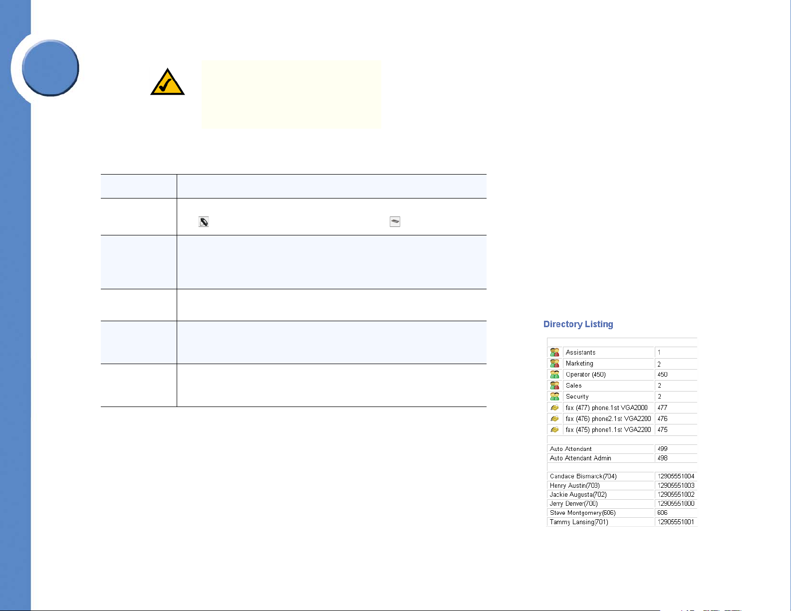
Linksys One Communications Solution
6
Chapter
NOTE: For SNR enabled users, 4 rings
will be added to the number of rings set
in this screen. This is to allow extra time
for the SNR target to answer the call
before the call is forwarded.
Refer to the following table for a description of the information displayed in the User Settings
screen.
Field or Button Description
User
First and Last
Name
Unlisted
Print User
Directory
The User area allows you to select a user to edit. Note: Phones are indicated by
the icon and voice gateways are indicated by the icon.
The First and Last Name fields display the name that you selected in the
dropdown list box described above. This name was originally entered in the
User Directory, however, you can change it here and it will be updated in the
User Directory. This name is also the one that appears on the Caller ID.
The Unlisted checkbox allows you to specify whether or not this name appears
in any directory listings.
The Print User Directory button allows you to generate a directory of users. The
user directory opens in a browser window; you can print the directory from
your browser. Unlisted users do not appear in the directory listing.
Print Quick
Reference
Chapter 6: Using the Phone Application
Changing Individual User Settings and Templates
The Print Quick Reference button allows you to generate a custom quick
reference guide of your phone. The quick reference guide opens in a browser
window; you can print the guide from your browser.
67
Page 74

Linksys One Communications Solution
Field or Button Description
You can use the Call Forward Always setting to forward all calls to one of the
following destinations:
• Auto Attendant. All incoming calls are forwarded to the Auto
Attendant.
• Personal Voicemail. All incoming calls are forwarded to personal
voicemail.
• Group. All incoming calls are forwarded to group extensions. There
can be multiple groups.
• Role. All incoming calls are forwarded to role extensions. There can
be multiple roles.
• Operators. All incoming calls are forwarded to the Operators.
• VM: Group. All incoming calls are forwarded to group voicemail.
There can be multiple groups.
Call Forward
Always Setting
• VM: Role. All incoming calls are forwarded to role voicemail. There
can be multiple roles.
• VM: Operators. All incoming calls are forwarded to the Operator's
voicemail.
• Extension of. All incoming calls are forwarded the specified extension.
• External. All incoming calls are forwarded to an external destination
(assuming forward offsite permission at the Users > Permissions
screen).
Note: The External destination is available only if the user has been given
permission in the Users > Permissions screen. The External target number must
include a steering digit (only IP Trunk, Local Trunk, or Inter-Site steering digits
are allowed). If a user does not have a DID extension, then only a Local Trunk
will be available for external call forwarding.
6
Chapter
68
You can specify how many times the phone rings before it is forwarded.
Chapter 6: Using the Phone Application
Changing Individual User Settings and Templates
Page 75

Linksys One Communications Solution
6
Chapter
Field or Button Description
You can use the Call Forward Busy or No Answer setting to forward busy or
unanswered calls to one of the following destinations:
• Never. Busy or unanswered calls are not forwarded. All phones with
this setting will continue to ring until they are answered.
• Auto Attendant. Busy or unanswered calls are forwarded to the Auto
Attendant.
• Personal Voicemail. Busy or unanswered calls are forwarded to
personal voicemail.
• Group. Busy or unanswered calls are forwarded to group extensions.
There can be multiple groups.
• Role. Busy or unanswered calls are forwarded to role extensions.
There can be multiple roles.
• Operators. Busy or unanswered calls are forwarded to the Operators.
• VM: Group. Busy or unanswered calls are forwarded to group
Call Forward
Busy or No
Answer Setting
Note: The External destination is only available if the user has been given
permission in the Users > Permissions screen. The External target number must
include a steering digit (only IP Trunk, Local Trunk, or Inter-Site steering digits
are allowed). If a user does not have a DID extension, then only a Local Trunk
will be available for external call forwarding.
voicemail. There can be multiple groups.
• VM: Role. Busy or unanswered calls are forwarded to role voicemail.
There can be multiple roles.
• VM: Operators. Busy or unanswered calls are forwarded to the
Operator's voicemail.
• Extension of. Busy or unanswered calls are forwarded the specified
extension.
• External. Busy or unanswered calls are forwarded to an external
destination (assuming forward offsite permission at the Users >
Permissions screen).
You can specify how many times the phone rings before it is forwarded.
To sele ct a u se r:
1. Click the dropdown list button ( ).
2. Select a name from the list.
Chapter 6: Using the Phone Application
Changing Individual User Settings and Templates
69
Page 76

To unlist a user from directory listings:
• Click the Unlisted checkbox so a check appears ( ).
To change Call Forward Always settings:
1. Click the Enable checkbox ( ).
2. Click the target button ( ) and choose a Call Forward Always target. If necessary, enter
additional extension or external number information.
3. Click Commit.
To Forward Busy or No Answer calls:
1. Click the “# Rings” button ( ) and specify the number of rings that occur before
forwarding the call.
2. Click the target button ( ) and choose a Call Forward Busy or No Answer setting.
3. Click Commit.
Forwarding Voicemail to E-mail
Linksys One Communications Solution
6
Chapter
Voicemail messages can be forwarded via e-mail. Voicemail box messages are sent as WAV
files. Various e-mail options can be assigned to each voicemail box as described below.
Voicemail Box Option Action
When a voicemail message arrives, a
Notification only
Voicemail attached
Voicemail attached and move VM message to
‘Saved’
70
notification e-mail is sent to the specified e-mail
addresses.
When a voicemail message arrives, a
notification e-mail with attached voicemail is
sent to the specified e-mail addresses.
When a voicemail message arrives, a
notification e-mail with attached voicemail is
sent to the specified e-mail addresses, plus the
voicemail message is moved from New
Messages to Saved Messages.
Chapter 6: Using the Phone Application
Changing Individual User Settings and Templates
Page 77

Linksys One Communications Solution
6
Chapter
NOTE: The Voicemail to email
forwarding options area is not
available if the system uses external
voicemail or if the user does not have a
personal voicemail box (as with a user
who is assigned to an FXS device).
To forward voicemail box messages to e-mail:
1. Click the Email Enable checkbox ( ).
2. Enter an e-mail address in the Email Address area.
NOTE: Multiple e-mail addresses can be
entered in the Email Address area. Use
a comma (,) between e-mail addresses.
3. Select a voicemail box option in the Mode area.
4. Click Commit to save your changes.
NOTE: This feature may take up to 3 to
5 minutes before forwarding voicemail
box messages to e-mail.
Configuring SNR
The SNR (Single Number Reach) section allows you to specify a number that rings
concurrently with the user’s number. For example, if SNR is directed to a user’s cell phone,
then his or her cell phone will ring at the same time that someone calls the user’s DID
number. The incoming call is routed to the phone that answers first. This section is not
Chapter 6: Using the Phone Application
Changing Individual User Settings and Templates
71
Page 78

available if SNR is not authorized for this user on the Users > SNR or Users > Permissions
screen.
Linksys One Communications Solution
6
NOTE: The SNR feature is not available
for FXS devices.
Enable
Enables SNR for this user. This checkbox is mirrored on the Users > SNR screen and on the
Call Forwarding / SNR task for this user’s phone. A target for the call must be specified as
defined below.
Tar ge t
Steering digit and phone number of the SNR destination. This SNR number is mirrored on
the Users > SNR screen for this user.
NOTE: A steering digit must precede the
SNR phone number. For example, if the
SNR phone number is 214-555-1212
and the steering digit for an IP Trunk is
9, then the number to enter into the
Target field would be 9-214-555-1212.
To enable SNR for a user:
Chapter
1. For each user, click an Enable checkbox ( ).
2. Enter an appropriate steering digit and SNR number.
3. Click Commit.
72
Chapter 6: Using the Phone Application
Changing Individual User Settings and Templates
Page 79

Linksys One Communications Solution
6
Chapter
Changing User Templates
The User Template screen allows you to customize the phone and AutoDial features that are
available on the user’s phone.
Chapter 6: Using the Phone Application
Changing Individual User Settings and Templates
73
Page 80
This screen is divided into two areas: the Template area and the Available area. The
Template area (located on the left side) shows the current phone and AutoDial feature button
assignments.
NOTE: The alternating colors in the
template indicate left and right side
buttons. The Available area (located on
the right side) shows the phone and
AutoDial features that are available but
not currently in use.
Possible features in the user template are defined as shown below. For more information
about these feature, refer to the Linksys One IP Phone User Guide.
Feature Function
1-to-1 Paging Enables 1-to-1 paging call.
After Hours Enables the user to switch to the after hours message.
Enables telephone numbers to be assigned to a button for quick
Autodial
Call Fwd Toggle
dialing or call transfer. When that button is pushed, it automatically
dials that number.
Enables all calls to be forwarded to the specified destination before
ringing.
Linksys One Communications Solution
6
Chapter
Conference Enables conference calling capability.
Do Not Disturb
Headset
Mobility
Park Enables a call to be put on hold (parked).
Redial Enables redial of the last number called.
Role Opt Out Enables the user to skip calls directed to their role.
SNR Enables the Single Number Reach function.
74
Enables the user to disable the phone ringer and call waiting features.
Calls get forwarded on no answer to their related destination.
Switches transmit and receive audio from the handset (or speaker) to
the headset.
Enables a call to be pushed to the specified number or enables an
active call to be pulled back to the user’s phone.
Chapter 6: Using the Phone Application
Changing Individual User Settings and Templates
Page 81

Linksys One Communications Solution
6
Chapter
Feature Function
Surveillance Enables the surveillance application (optional).
Transfer Enables the user to transfer a call to another destination.
Voicemail Enables the user to access voicemail.
Using Move Icons
You can move and reorder the phone and AutoDial features on your button template as
described below.
To move an available phone or AutoDial feature to your button template:
1. Locate a phone or AutoDial feature in the Available area.
2. Drag the AutoDial or phone feature, using its move icon ( ), so that the top of the mouse
pointer (finger tip) falls anywhere on the desired unused template button location
.
NOTE: Some objects may be mapped to
multiple buttons. If an object cannot be
moved, remove the buttons above and
below the intended location.
3. Click Commit.
To move a phone or AutoDial feature from your button template:
1. Locate a phone or AutoDial feature in your button template.
2. Drag the AutoDial feature, using its move icon ( ), to the Available area.
NOTE: No more than 12 single button
features can be moved to the Available
area.
3. Click Commit.
Chapter 6: Using the Phone Application
Changing Individual User Settings and Templates
75
Page 82

To reorder the button assignments in your button template:
1. Locate a phone or AutoDial feature in your button template.
2. Drag the AutoDial or phone feature, using its move icon ( ), so that the top of the mouse
pointer (finger tip) falls anywhere on the desired unused template button location
.
3. Click Commit.
Using Direction Icons
You can also move a phone or AutoDial features by clicking the right or left direction icons (
or ).
To move a phone or AutoDial feature using the Direction icons:
1. Click on the right or left direction icons ( or ) to move the feature to the other side.
2. Click Commit.
NOTE: When moving a feature from the
Available area to the Template area, the
feature is moved to the next available
unused slot starting from the top.
Linksys One Communications Solution
6
Chapter
NOTE: No more than 12 features can
be moved to the Available area.
Editing AutoDial Features
You can edit the AutoDial features to contain names and numbers that are assigned to your
button template. Note: The numbers entered in the Number field of an AutoDial must include
all digits as if they were dialed from your phone. For example, if your normal calling
sequence is 9 to reach an outside extension, then 972-555-1212, enter 9-972-555-1212
into the AutoDial Number field.
76
Chapter 6: Using the Phone Application
Changing Individual User Settings and Templates
Page 83

6
Linksys One Communications Solution
To edit AutoDial features:
1. Click the Name side of the AutoDial feature and enter a name.
2. Click the Number side of the AutoDial feature and enter a phone number.
3. Click Commit.
Chapter
Printing the Template
You can print the template from your browser window using Adobe® Reader® software.
Download Adobe Reader from http://www.adobe.com/products/acrobat/readstep2.html.
To print your button template:
1. Click the Print Template button. The application will create a PDF version of your
template.
2. Print the template and cut to the correct size.
3. Install the new template on your phone.
Configuring and Viewing Call Target Information
The Call Targets tab allows you to view group and role definitions, configure voicemail
boxes, assign trunks, and configure call forwarding.
Chapter 6: Using the Phone Application
Configuring and Viewing Call Target Information
77
Page 84
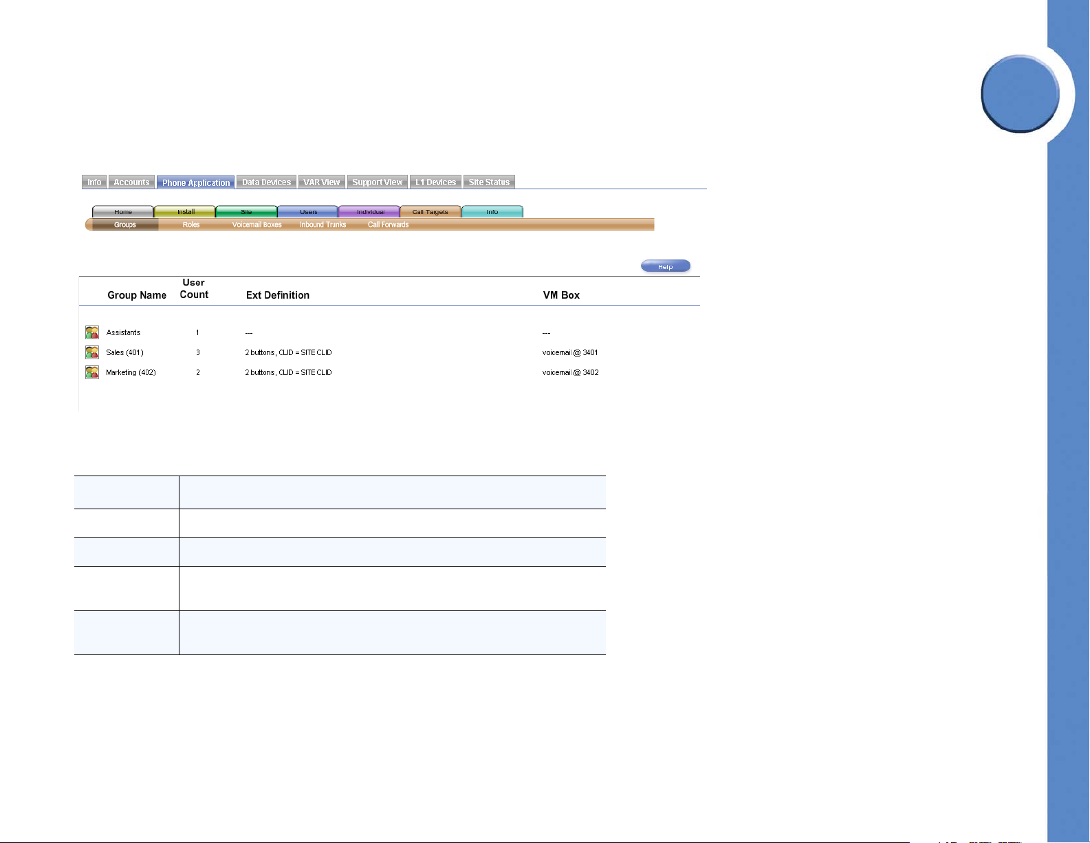
Linksys One Communications Solution
Viewing Group Information
The Groups screen allows you to quickly see relevant information on each group in the
system. This screen is informational only; nothing can be changed on this screen.
Refer to the following table for a description of the information displayed in the Groups
screen.
6
Chapter
Field Description
Group Name Name and extension of the group as defined in Install > Define Groups.
User Count Number of users in each group.
Ext Definition
VM Box
78
Definition of the extension showing number of buttons and the CLID. These
settings are defined in the Install > Define Groups screen.
Destination of a voicemail call. These settings are defined in the Install > Define
Groups screen.
Chapter 6: Using the Phone Application
Configuring and Viewing Call Target Information
Page 85

Linksys One Communications Solution
6
Chapter
Viewing Role Information
The Roles screen allows you to quickly see relevant information for each role in the system.
This screen is informational only; nothing can be changed on this screen.
Refer to the following table for a description of the information displayed in the Roles screen.
Field Description
Role Name Name and extension of the group as defined in Install > Define Roles.
User Count Number of users in each role.
Ext Definition
VM Box
Chapter 6: Using the Phone Application
Configuring and Viewing Call Target Information
Definition of the extension showing number of buttons and the CLID. These
settings are defined in the Install > Define Roles screen.
Destination of a voicemail call. These settings are defined in the Install > Define
Roles screen.
79
Page 86

Linksys One Communications Solution
Defining System Voicemail Boxes
For groups and roles, the Voicemail Boxes screen allows you to enable the voicemail to email forwarding feature.
NOTE: The Voicemail Boxes tab is not
shown for systems that have external
voicemail.
6
Chapter
Voicemail box e-mail messages are sent as WAV files. Various e-mail options can be
assigned to each voicemail box as described in the table below.
Voicemail Box Option Action
Notification only
80
When a voicemail message arrives, a notification e-mail is
sent to the specified e-mail addresses.
Chapter 6: Using the Phone Application
Configuring and Viewing Call Target Information
Page 87
Linksys One Communications Solution
6
Chapter
Voicemail Box Option Action
When a voicemail message arrives, a notification e-mail
Voicemail attached
Voicemail attached and move VM
message to “Saved”
To forward call target voicemail box messages to e-mail:
1. Click the Email Enable checkbox ( ).
2. Enter an e-mail address in the Email Address area.
NOTE: Multiple e-mail addresses can be
entered in the Email Address area. Use
a comma (,) between e-mail addresses.
3. Click the target button ( ) and select a voicemail box option in the Mode area.
4. Click Commit.
with the attached voicemail is sent to the specified e-mail
addresses.
When a voicemail message arrives, a notification e-mail
with attached voicemail is sent to the specified e-mail
addresses, plus the voicemail message is moved from New
Messages to Saved Messages.
NOTE: This feature may take up to 3 to
5 minutes before forwarding voicemail
box messages to e-mail.
Chapter 6: Using the Phone Application
Configuring and Viewing Call Target Information
81
Page 88
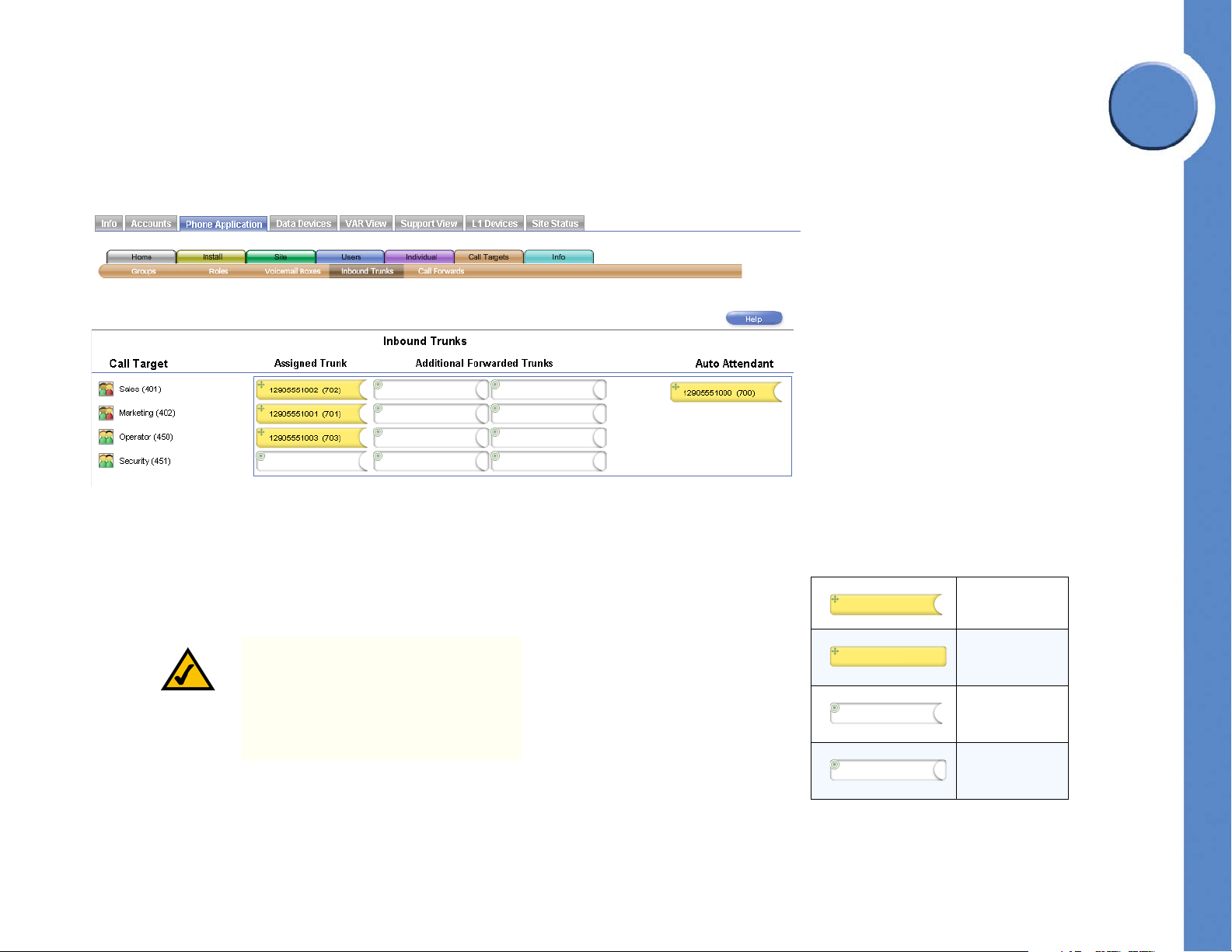
Linksys One Communications Solution
DID Trunk
Object
non-DID Trunk
Object
DID Trunk Slot
non-DID Trunk
Slot
Assigning Inbound Trunks to Call Targets
The Inbound Trunks screen allows you to assign inbound trunks to call targets. Each call
target can be assigned up to three trunks; however, only a DID trunk can be assigned in the
Assigned Trunk column.
Notice that DID trunk objects have rounded edges on their right side, and non-DID trunk
objects have square edges on theirs. Also notice that there are two types of slots into which
the DID and non-DID trunk objects are placed: those with rounded edges and those with
square edges. DID trunk objects can be placed into either type of slot, but non-DID trunk
objects can only be inserted into the square-edged slots. This mechanism ensures that only
DID trunks are assigned as “Assigned Trunk.”
6
Chapter
82
NOTE: This screen is related to the Users
> Inbound Trunks screen; any
extensions assigned to the Auto
Attendant in this screen will also be
assigned to the Auto Attendant in the
Users > Inbound Trunks screen.
Chapter 6: Using the Phone Application
Configuring and Viewing Call Target Information
Page 89

6
Linksys One Communications Solution
Refer to the following table for a description of the information displayed in the Inbound
Trunks screen.
Field Description
Call Target Name of the call target.
Chapter
Default extension for the group. Note: Only a DID trunk can be assigned as an
Assigned Trunk
Additional
Forwarded
Trunks
Auto Attendant Inbound trunks assigned to the Auto Attendant.
To assign a DID trunk to an Assigned Trunk:
1. Drag the move icon ( ) of a DID trunk object anywhere inside an Assigned Trunk slot.
2. Click Commit.
To assign a non-DID trunk to Call Target:
1. Drag the move icon ( ) of a non-DID trunk object anywhere inside a non-DID slot.
Assigned Trunk. For customers using only local trunks, this column is not
available.
Trunks that are forwarded to the extension in the “Assigned Trunk” column.
NOTE: When dragging objects to a slot,
ensure that the top of the mouse pointer
(finger tip) is inside the destination slot.
NOTE: When dragging objects to a slot,
ensure that the top of the mouse pointer
(finger tip) is inside the destination slot.
2. Click Commit.
Chapter 6: Using the Phone Application
Configuring and Viewing Call Target Information
83
Page 90

To assign a trunk to an Auto Attendant:
1. Drag the move icon ( ) of a trunk object into the Auto Attendant column.
2. Click Commit.
Configuring Call Forward Options
The Call Forwards screen allows you to specify call forward options for specific call targets.
For “Call Forward Busy or No Answer” calls, you can specify the number of rings before
forwarding and the call.
Linksys One Communications Solution
6
Chapter
84
Chapter 6: Using the Phone Application
Configuring and Viewing Call Target Information
Page 91

6
Linksys One Communications Solution
Refer to the following table for a description of the information displayed in the Call
Forwards screen.
Field Description
Chapter
Call Forward
Always
You can use the Call Forward Always setting to forward all calls to one of the
following destinations:
• Auto Attendant. All incoming calls are forwarded to the Auto
Attendant.
• VM: Group/Role. All incoming calls are forwarded to the Group or
Role voicemail.
• Group. All incoming calls are forwarded to group extensions. There
can be multiple groups.
• Role. All incoming calls are forwarded to role extensions. There can
be multiple roles.
• Operators. All incoming calls are forwarded to the Operators.
• VM: Group. All incoming calls are forwarded to group voicemail.
There can be multiple groups.
• VM: Role. All incoming calls are forwarded to role voicemail. There
can be multiple roles.
• VM: Operators. All incoming calls are forwarded to the Operator's
voicemail.
• Extension of. All incoming calls are forwarded the specified extension.
• External. All incoming calls are forwarded to an external destination.
Chapter 6: Using the Phone Application
Configuring and Viewing Call Target Information
85
Page 92

Linksys One Communications Solution
Field Description
Call Forward
Busy or No
Answer
This option determines whether calls routed to a user are forwarded elsewhere
if the extension is busy or if there is no answer. You can use the Call Forward
Busy or No Answer setting to forward busy or unanswered calls to one of the
following destinations:
• Never. Busy or unanswered calls are not forwarded. All phones with
this setting will continue to ring until they are answered.
• Auto Attendant. Busy or unanswered calls are forwarded to the Auto
Attendant.
• VM: Group/Role. Busy or unanswered calls are forwarded to the
Group or Role voicemail.
• Group. Busy or unanswered calls are forwarded to group extensions.
There can be multiple groups.
• Role. Busy or unanswered calls are forwarded to role extensions.
There can be multiple roles.
• Operators. Busy or unanswered calls are forwarded to the Operators.
• VM: Group. Busy or unanswered calls are forwarded to group
voicemail. There can be multiple groups.
• VM: Role. Busy or unanswered calls are forwarded to role voicemail.
There can be multiple roles.
• VM: Operators. Busy or unanswered calls are forwarded to the
Operator's voicemail.
• Extension of. Busy or unanswered calls are forwarded the specified
extension.
• External. Busy or unanswered calls are forwarded to an external
destination.
6
Chapter
To change the Call Forward Always settings:
1. Click a checkbox ( ) in the Enable column of a call target. All calls will be forwarded to
the target destination.
2. If necessary, click the options button ( ) to specify a different target destination for the
forwarded call. If you select the “Extension of” or “External” option, a text box appears
in which you can enter a number. If the number is external, you must add a steering
digit.
3. Click Commit.
86
Chapter 6: Using the Phone Application
Configuring and Viewing Call Target Information
Page 93

6
Chapter
Linksys One Communications Solution
To change the Call Forward Busy or No Answer settings:
1. Under the # Rings column, click the options button ( ) for a user and select the number
of rings. This specifies how many rings occur before the call is forwarded.
2. Under the Target column, click the options button ( ) and select a call forward
destination. If you select the “Extension of” or “External” option, a text box appears in
which you can enter a number. If the number is external, you must add a steering digit.
3. Click Commit.
Viewing System Information
The Inbound Calls screen allows you to quickly see the trunk path for each trunk in the
system. This screen is informational only; nothing can be changed on this screen.
Chapter 6: Using the Phone Application
Viewing System Information
87
Page 94

Refer to the following table for a description of the information displayed in the Inbound
“Will Ring” Icons
Auto Attendant
User
Role
Group
Fax
Paging system
Trunks screen.
Linksys One Communications Solution
6
Field Description
Call on Trunk Number assigned to the trunk.
Trunk Type Type of trunk. Choices are IP DID or local trunk.
Call forward Always settings as defined in the following screens:
Are Currently
Forwarded To
Will Ring
If Busy or Not
Answered, Will
Ring
• Users > Call Forwards
• Individual > User Settings
• Call Targets > Call Forwards
Destination of an incoming call on the trunk. The type of destination is shown
graphically.
Call Forward Busy or No Answer settings as defined in the following screens:
•Users > Call Forward
• Individual > User Settings
• Call Targets > Call Forwards
Chapter
88
Chapter 6: Using the Phone Application
Viewing System Information
Page 95

Linksys One Communications Solution
7
Chapter
Viewing the Surveillance Application
The Linksys One system provides video surveillance capabilities when equipped with an
APP1000 Application Server Appliance and a Linksys Business Series PVC2300 camera. A
new tab, Surveillance, automatically appears on the Linksys One Administration interface
when the surveillance application is installed.
The Surveillance application on the Administration Interface is like the operation of the
Surveillance Application on the phones, refer to the Video Surveillance Application User
Guide for more details on its operation.
Chapter 7: Viewing the Surveillance Application
89
Page 96

To view the Surveillance application from the Administration interface, the web browser
client must be connected to the same subnet (LAN) as the Services Router and the user must
be logged in as described in the ”Accessing the Linksys One Portal” section on page 4.
NOTE: The Surveillance tab will not
appear if the application is not running
or if you are not logged in as described
above.
Adding a Camera to the Administration Interface
Here’s how to access the Video Surveillance Application from the Administration Interface.
1. Click the Surveillance tab. The Surveillance Application shows the cameras that are
available.
2. Click a camera that you want to monitor.
Linksys One Communications Solution
7
Chapter
90
Chapter 7: Viewing the Surveillance Application
Adding a Camera to the Administration Interface
Page 97
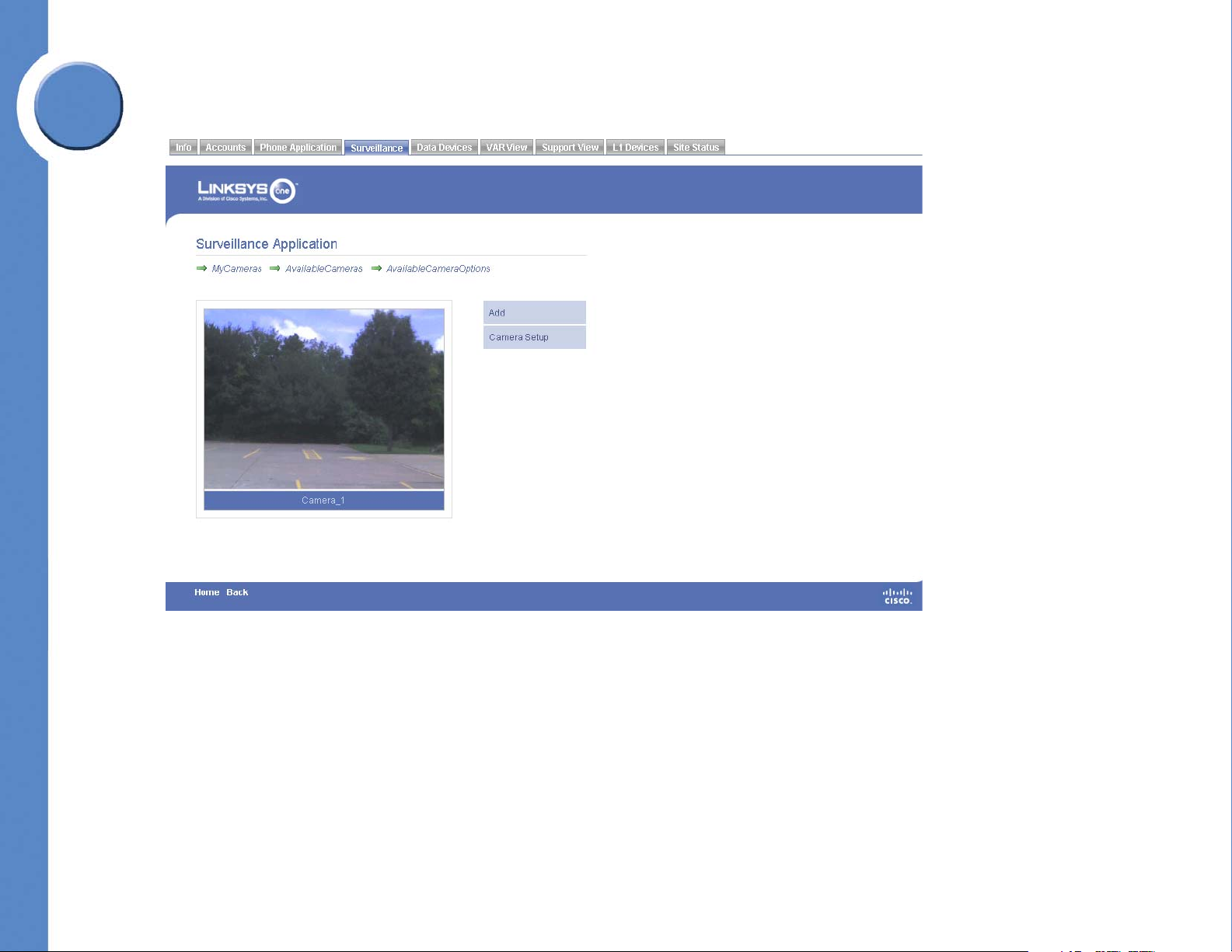
7
Chapter
Linksys One Communications Solution
3. Click Add. The camera is added to My Cameras.
Removing a Camera from the Administration Interface
You can remove the camera from the Administration Interface as follows.
1. Click the Surveillance tab.
2. Click MyCameras.
3. Click a camera to remove.
Chapter 7: Viewing the Surveillance Application
Removing a Camera from the Administration Interface
91
Page 98

4. Click Remove. The camera is removed from MyCameras and is listed under
AvailableCameras.
Linksys One Communications Solution
7
Chapter
To Access the Camera Software
You can access additional camera functionality through the software that came with the
camera.
1. Click the Surveillance tab.
2. Click MyCamera.
92
Chapter 7: Viewing the Surveillance Application
To Access the Camera Software
Page 99
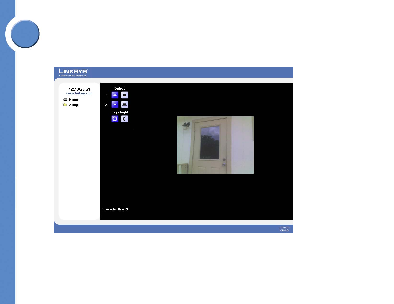
7
Chapter
Linksys One Communications Solution
3. Click a camera.
4. Click Camera Setup. A window opens showing the camera software. Refer to the
documentation that came with the camera for more details regarding the camera
software.
Chapter 7: Viewing the Surveillance Application
To Access the Camera Software
93
Page 100

Linksys One Communications Solution
Managing Data Devices
Data settings prevent unauthorized users from gaining access to your Linksys One network
through another network. Data settings are configurable from the Data Devices tab in the
Linksys One Portal.
These sections help you manage the data devices on your network:
• ”Viewing the Status of Data Devices” section on page 94
• ”Adding DNS Names for Static IP Devices” section on page 95
• ”Allowing Access to Network Services” section on page 96
• ”Using the Services Router Advanced Interface” section on page 98
Viewing the Status of Data Devices
The Status screen lists all data devices that have been assigned an IP address by the Services
Router. The Status window is a good way to verify that the Services Router can “see” other
devices on the system. If a device is not listed here, it is not communicating with the Services
Router. Note that only Dynamic Host Configuration Protocol (DHCP) devices display in this
window. If a device does not appear, it may be because it is assigned a static IP address.
8
Chapter
To access the Status window:
•Click the Data Status > Status tab.
You’ll see the following status about data devices on your network:
Item Description
Hostname
IP
94
A unique name for the device. Any device connected to the system must
have a host name.
The Internet Protocol (IP) address of the device. The IP address is either
assigned dynamically using DHCP or you can assign a static IP address on
the Static IPs page. Devices assigned a static IP address do not display in
this window.
Chapter 8: Managing Data Devices
Viewing the Status of Data Devices
 Loading...