

Page 1
Getting Started and Product Document of
Compliance for the Cisco IR1101 Industrial
Integrated Services Router
IMPORTANT! READ ALL THE SAFETY INFORMATION
B
EFORE INSTALLING THE HARDWARE
Cisco Part Number 78-101332-01A0
Introduction, page 1
Items Shipped with your Router, page 1
Equipment that you supply, page 2
Related Documentation, page 2
Installation Warning and Caution Statements for Hazardous Locations Environments, page 2
Grounding the Router, page 4
Connecting DC Power, page 5
Connecting to the Router Gateway Ports, page 7
Connecting to the USB Port, page 7
Installing a Pluggable Module, page 8
EMC Information, page 12
Declaration of Conformity with regard to the R&TTE Directive 2014/53/EU & Medical Directive 93/42/EEC, page 16
Introduction
The purpose of this document is to provide the installer the necessary information for installing the Cisco IR1101
Industrial Integrated Services Router. The documentation is on-line, and subject to change. Make sure that you are
downloading or viewing on-line the latest version before beginning an installation.
This document also contains Product Compliance and Safety information as well as Declaration of Conformity.
Items Shipped with your Router
Unpack the box and verify that all items listed on the invoice were shipped with the Cisco IR1101.
Cisco Systems, Inc. www.cisco.com
1
Page 2

Getting Started and Product Document of Compliance for the Cisco IR1101 Industrial Integrated Services Router
The following items are shipped with your router:
This document
Power Connector
Grounding Lug Kit
Equipment that you supply
ESD-preventive cord and wrist strap.
Wire-stripping tools for stripping 14- and 18-gauge wires
Crimping tool
Ratcheting torque screwdriver that exerts up to 15 in-lb (1.69 N-m) of pressure.
Related Documentation
To access resources or to display the latest Cisco 1101 Series Router documentation on-line, go to this URL:
https://www.cisco.com/c/en/us/support/routers/1101-industrial-integrated-services-router/model.html
This portal has all of the information you need to get to know your router, install and configure it, as well as access
software. You will see the following categories as well as other important information:
All support information for Cisco IR1101 Series Industrial Integrated Services Routers: Provides the most
requested resources and a list of all of the models in the series.
Release and General Information: Links to the Software Download site, Compatibility Information, Licensing
Information, and Product Release notes.
Install and Upgrade: This is your starting point for Installing the Router. look under The Install and Upgrade Guide
section for this model,
Configure: These links provide configuration information. Look first under the Configuration Guide section for this
model.
Other important and helpful links to Cisco information are here:
Cisco.com: www.cisco.com
Warranty and EULA Information: https://www.cisco.com/c/en/us/products/warranty-listing.html
Cisco Marketplace: www.cisco.com/pcgi-bin/marketplace/welcome.pl
Cisco Product Documentation: www.cisco.com/go/techdocs
Cisco Support: www.cisco.com/cisco/web/support/index.html
Installation Warning and Caution Statements for Hazardous Locations Environments
Warning: IMPORTANT SAFETY INSTRUCTIONS
This warning symbol means danger. You are in a situation that could cause bodily injury. Before you work on any
equipment, be aware of the hazards involved with electrical circuitry and be familiar with standard practices for
preventing accidents. Use the statement number provided at the end of each warning to locate its translation in the
translated safety warnings that accompanied this device. Statement 1071
2
Page 3

Getting Started and Product Document of Compliance for the Cisco IR1101 Industrial Integrated Services Router
Warning: Explosion Hazard - The area must be known to be nonhazardous before installing, servicing, or replacing
the unit. Statement 1082
Warning: In order to comply with FCC radio frequency (RF) exposure limits, antennas for this product should be
located a minimum of 11.8 in. (30 cm) or more from the body of all persons. Statement 332
Warning: Read the installation instructions before connecting the system to the power source. Statement 1004
Warning: This product relies on the building’s installation for short-circuit (overcurrent) protection. Ensure that the
protective device is rated not greater than: 60Vdc minimum, 5A maximum. Statement 1005
Warning: This unit is intended for installation in restricted access areas. A restricted access area can be accessed
only through the use of a special tool, lock and key, or other means of security. Statement 1017
Warning: This equipment must be grounded. Never defeat the ground conductor or operate the equipment in the
absence of a suitably installed ground conductor. Contact the appropriate electrical inspection authority or an
electrician if you are uncertain that suitable grounding is available. Statement 1024
Warning: Only trained and qualified personnel should be allowed to install, replace, or service this equipment.
Statement 1030
Warning: Ultimate disposal of this product should be handled according to all national laws and regulations.
Statement 1040
Warning: To prevent the system from overheating, do not operate it in an area that exceeds the maximum
recommended ambient temperature of 140°F (60°C) Statement 1047
Warning: Use twisted-pair supply wires suitable for 86°F (30°C) above surrounding ambient temperature outside
the enclosure. Statement 1067
Warning: Installation of the equipment must comply with local and national electric codes. Statement 1074
Warning: Avoid using or servicing any equipment that has outdoor connections during an electrical storm. There
may be a risk of electric shock from lightning. Statement 1088
Warning: The product is to be connected to a IEC 60950 compliant limited power source (LPS). Statement 170
Caution: The equipment shall only be used in an area of not more than pollution degree 2, as defined in IEC 60664-1.
The equipment shall be installed in a certified enclosure that provides a degree of protection not less than IP 54 in
accordance with IEC 60079-15.
Caution: When installed in a minimum IP54 certified enclosure, the product must be made accessible by tool only.
Caution: Airflow around the Router must be unrestricted. The dimensions (height x width x depth) are 13.3(h) x 12.5(d)
x 5.8(w) cm (5.22" x 4.92" x 2.27). To prevent the Router from overheating, there must be a minimum of 1.0 in. (25.4
mm) around all surfaces of the Router.
Contact your Cisco Technical Assistance Centre (TAC) if tighter spacings are required.
Caution: This equipment is suitable for use in Class I, Division 2, Groups A, B, C, D, or only nonhazardous locations.
NOTE: Marked DC Input ratings: 12-48Vdc, 2.8A.
NOTE: This product is suitable for use in environmental air space in accordance with section 300.22.C of the National
Electrical Code and sections 2-128, 12-010(3), and 12-100 of the Canadian Electrical Code, Part 1, C22.1. You should
not install the power supply or power injector in air handling spaces.
NOTE: The maximum ambient operating temperature range is –40 to 140°F (–40 to 60°C).
3
Page 4
Getting Started and Product Document of Compliance for the Cisco IR1101 Industrial Integrated Services Router
Grounding the Router
Make sure to follow any grounding requirements at your site. The ground lug is supplied with the device.
Warning: This equipment must be grounded. Never defeat the ground conductor or operate the equipment in the
absence of a suitably installed ground conductor. Contact the appropriate electrical inspection authority or an
electrician if you are uncertain that suitable grounding is available. Statement 1024
Warning: This equipment is intended to be grounded to comply with emission and immunity requirements. Ensure
that the switch functional ground lug is connected to earth ground during normal use. Statement 1064
For NEC-compliant grounding, use size 16 AWG (1.5 mm2) or larger copper wire and a ring terminal with an inner
diameter of 1/4 in. (6 to 7 mm).
For EN/IEC 60950-compliant grounding, use size 18 AWG (1 mm2) or larger copper wire.
Caution: Use at least a 2.3mm conductor to connect to the external grounding screw.
To ground the router to earth ground by using the ground screw, follow these steps:
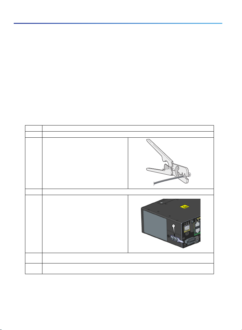
1. Locate the ground lug in the packaging kit. Store the ground screw for later use.
2. Use a wire stripping tool to strip the 14-18 AWG (2.08-1.31mm²) grounding wire to 0.22 in. (5.56 mm).
3. Insert the ground wire into the ring terminal lug,
and using a crimping tool, crimp the terminal to the
wire.
4. Slide the ground screws through the ground lug.
5. Insert the ground screws into the two screw
positions (1) shown in the graphic.
332163
6. Use a ratcheting torque screwdriver to tighten the ground screw and ring terminal to the router side
panel to a torque of 8 to 10 inch-pound (0.9 to 1.1 newton meter).
7. Attach the other end of the ground wire to a grounded bare metal surface, such as a ground bus, a
grounded DIN rail, or a grounded bare rack.
4
Page 5

Getting Started and Product Document of Compliance for the Cisco IR1101 Industrial Integrated Services Router
Connecting DC Power
Warning: When you connect or disconnect the power and/or alarm connector with power applied, an electrical arc
can occur. This could cause an explosion in hazardous area installations. Be sure that all power is removed from the
switch and any other circuits. Be sure that power cannot be accidentally turned on or verify that the area is
nonhazardous before proceeding. Statement 1058
Warning: Explosion Hazard—Substitution of components may impair suitability for Class I, Division 2/Zone 2.
Statement 1083
Warning: Connect the unit only to DC power source that complies with the safety extra-low voltage (SELV)
requirements in IEC 60950 based safety standards. Statement 1033
Plugs and Pin-Outs
The following is a brief overview of connecting to DC power. Details can be found in the Cisco IR1101 Industrial
Integrated Services Router Hardware Installation Guide and should be understood before beginning. See Related
Documentation, page 2.
The IR1101 ships with a DC power accessory kit.
The power entry receptacle is on the IR1101. The pin-outs are shown in Figure 1. Descriptions are shown in Tab le 1.
5
Page 6
Getting Started and Product Document of Compliance for the Cisco IR1101 Industrial Integrated Services Router
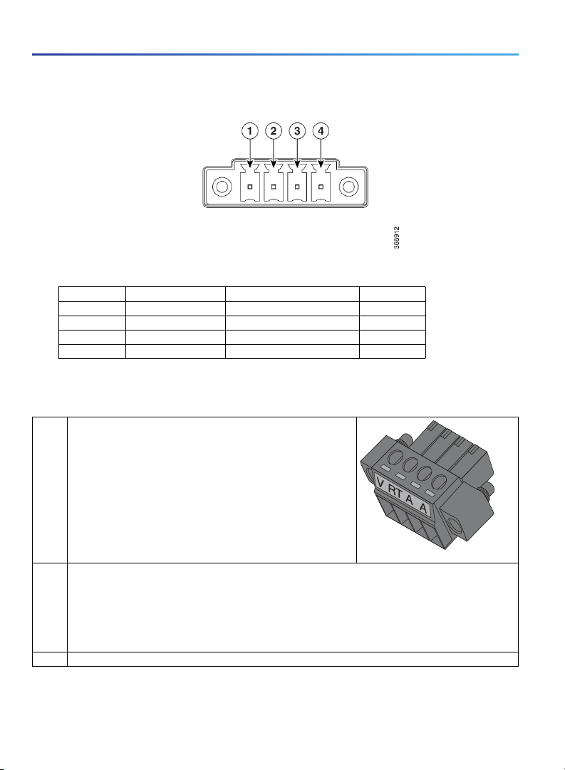
Figure 1 Power Connector Pin-outs
Table 1 Power connector Descriptions
Pin Number Name Description Color
1 DC In + DC Power Positive Input Red
2 DC In - DC Power Return (GND-) Black
3AC Alarm Common N/A
4AI Alarm Input N/A
Wiring the DC Power
To connect the DC power on your Cisco IR1101, follow these steps:
1. Locate the power and alarm connector on the router front panel.
NOTE: Your connector may not have the labels V RT A A.
In the labeled connector, the pins are:
V—Positive DC power connection
RT— Return DC power connection
A— Alarm Common
A— Alarm Input
2. Identify the connector positive and return DC power connections. The connections left to right are:
1—Positive DC power connection
2—Return DC power connection
3—Alarm Common
4—Alarm Input
3. Measure two strands of twisted-pair copper wire (18-to-20 AWG) long enough to connect to the DC power source.
391920
6
Page 7

Getting Started and Product Document of Compliance for the Cisco IR1101 Industrial Integrated Services Router
4. Using an 18-gauge wire-stripping tool, strip each of the two twisted pair
wires coming from each DC-input power source to 0.25 inch (6.3 mm)
± 0.02 inch (0.5 mm). Do not strip more than 0.27 inch (6.8 mm) of
insulation from the wire. Stripping more than the recommended amount of
wire can leave exposed wire from the power connector after installation.
5. Remove the two captive screws that attach the power and alarm connector to the router, and remove the connector.
6. On the power and alarm connector, insert the exposed part of the positive
wire into the connection labeled "V" and the exposed part of the return
wire into the connection labeled "RT". Make sure that you cannot see any
wire lead. Only wire with insulation should extend from the connector.
NOTE: Use the same method for wiring the alarm connections.
1
333084
1—Power connector captive screws
7. Use a ratcheting torque flathead screwdriver to torque the power connector captive screws (above the installed wire
leads) to 2 in-lb (0.23 N-m).
8. Connect the other end of the positive wire to the positive terminal on the DC power source, and connect the other
end of the return wire to the return terminal on the DC power source.
Connect the other end of the Alarm wires to your alarm source.
Connecting to the Router Gateway Ports
For hazardous location environments, follow these warnings when connecting to the destination ports (antenna, serial,
Ethernet, and console ports).
Warning: If you connect or disconnect the console cable with power applied to the switch or any device on the
network, an electrical arc can occur. This could cause an explosion in hazardous location installations. Be sure that
power is removed or the area is nonhazardous before proceeding. Statement 1080
Warning: Do not connect or disconnect cables to the ports while power is applied to the switch or any device on
the network because an electrical arc can occur. This could cause an explosion in hazardous location installations.
Be sure that power is removed from the switch and cannot be accidentally be turned on, or verify that the area is
nonhazardous before proceeding. Statement 1070
Connecting to the USB Port
NOTE: If you are connecting to the USB port:
- a connection (to the USB port) can only be made in a non-hazardous environment
- the USB port cover must be reinstalled before the router can be deployed in a hazardous environment
7
391942
Page 8

Getting Started and Product Document of Compliance for the Cisco IR1101 Industrial Integrated Services Router
Installing a Pluggable Module
For hazardous location environments, follow these warnings when installing a pluggable module.
Warning: Explosion Hazard - The area must be known to be nonhazardous before installing, servicing, or replacing
the unit. Statement 1082
1. Remove the blank plate by unscrewing the latch lock screw(1) that holds the plate secure. See Figure 2.
Figure 2 Latch Lock Screw
2. Slide the blank plate out of the device.
3. Prepare the cellular modem module by inserting the micro SIMs applicable for your modems into the device. Remove
the screw (1) holding the access plate in place that covers the SIM slots. It is located on the side of the module, as
shown in Figure 3
Figure 3 Sim Access Plate
4. Install your SIMs as shown in Figure 4. Make note of the proper slot number and SIM orientation.
8
Page 9

Getting Started and Product Document of Compliance for the Cisco IR1101 Industrial Integrated Services Router
Figure 4 Sim Installation
Item Description
1Micro SIMs
2SIM 0 (towards the device)
3 SIM 1 (away from the device)
5. Push in each SIM unt il it clicks into place. When the SIMs are installed, re-attach the access plate previously removed
with a screwdriver. Torque to 2.8 to 3.8 inch-lbs (0.9-1.1 newton meter).
6. If your Pluggable Module is the type that has a USB port, make sure that the USB cover is properly installed. Place
the USB cover (1) with the plug indentation against the USB port (2). The half circle of the USB cover fits behind the
latch lock screw. See Figure 5 for details.
9
Page 10

Getting Started and Product Document of Compliance for the Cisco IR1101 Industrial Integrated Services Router
Figure 5 USB Port Cover Installation
7. Tighten the latch lock screw to a torque of 2.8 to 3.8 inch-lbs (0.3 to 0.4 newton meter). Refer to Figure 6 for a
finished USB cover installation.
Figure 6 U SB Cover Finished Installation
8. Slide the Pluggable Module into the device as shown in Figure 7. The latch lock screw (1) aligns with the screw hole
(2) on the front of the device. Push the Pluggable Module all the way into the device until you feel it seat, and then
torque the latch lock screw 8-10 inch-lbs. (0.9-1.1 newton meter).
10
Page 11

Getting Started and Product Document of Compliance for the Cisco IR1101 Industrial Integrated Services Router
Figure 7 Pluggable Module Insert
9. Attach your antennas to the ports on the pluggable module. There are different instructions for each antenna type,
be sure to consult the antenna documentation for proper orientation and torque to install them.
10. If no antennas are being installed on a port, make sure the caps are installed on the connector.
11
Page 12

Getting Started and Product Document of Compliance for the Cisco IR1101 Industrial Integrated Services Router
Hazardous Locations Standards and Marking Strings
The following standards were used for the
hazardous locations approvals and certifications:
UL 121201, Ed. 9
CAN/CSA C22.2 No. 60079-0-11 Ed. 2
CAN/CSA C22.2 No. 60079-15-12 Ed. 1
CSA C22.2 No. 213 Ed. 3
EN 60079-0:2012
EN 60079-15:2010
IEC 60079-0 6th Edition
IEC 60079-15 4th Edition
UL 60079-0, 5th Ed, 2009-10-21
UL 60079-15, 3rd Ed, 2009-7-17
The following hazardous locations strings are
provided on the router:
Class 1, Div 2, Groups A B C D
Class I, Zone 2, AEx nA IIC T4 Gc
II 3G, Ex nA IIC T4 Gc
DEMKO 18 ATEX 2089X
Class 1, Zone 2, AEx nA IIC T4 Gc
EMC Information
For EMC and safety information, see the Regulatory Compliance and Safety Information.
Class A Notice for FCC
Modifying the equipment without Cisco’s authorization may result in the equipment no longer complying with FCC
requirements for Class A digital devices. In that event, your right to use the equipment may be limited by FCC regulations,
and you may be required to correct any interference to radio or television communications at your own expense.
This equipment has been tested and found to comply with the limits for a Class A digital device, pursuant to Part 15 of
the FCC Rules. Operation is subject to the following two conditions:
1. This device may not cause harmful interference, and
2. This device must accept any interference received, including interference that may cause undesired operation.
This equipment has been tested and found to comply with the limits of a Class A digital device, pursuant to Part 15 of
the FCC Rules. These limits are designed to provide reasonable protection against harmful interference when the
equipment is operated in a residential environment. This equipment generates, uses, and radiates radio frequency
energy, and if not installed and used in accordance with the instructions, may cause harmful interference. However, there
is no guarantee that interference will not occur. If this equipment does cause interference to radio or television reception,
which can be determined by turning the equipment off and on, the user is encouraged to correct the interference by one
of the following measures:
12
Page 13

Getting Started and Product Document of Compliance for the Cisco IR1101 Industrial Integrated Services Router
Reorient or relocate the receiving antenna.
Increase separation between the equipment and receiver.
Connect the equipment to an outlet on a circuit different from which the receiver is connected.
Consult the dealer or an experienced radio/TV technician.
Caution: The Part 15 radio device operates on a non-interference basis with other devices operating at this frequency
when using the integrated antennas. Any changes or modification to the product not expressly approved by Cisco could
void the user's authority to operate this device.
Industry Canada
Canadian Compliance Statement
Cisco® IR1101 Industrial Integrated Services Router Model
IR1101
Cisco® IR1101 Industrial Integrated Services Router PIDS
IR1101-K9
This Class A Digital apparatus meets all the requirements of the Canadian Interference-Causing Equipment Regulations.
This device complies with Class A Limits of Industry Canada. Operation is subject to the following two conditions:
1. This device may not cause harmful interference, and
2. This device must accept any interference received, including interference that may cause undesired operation.
Cisco® IR1101 Industrial Integrated Services Routers are certified to the requirement s of RSS-210. The use of this device
in a system operating either partially or completely outdoors may require the user to obtain a license for the system
according to the Canadian regulations. For further information, contact your local Industry Canada office.
This device has been designed to operate w ith antennas having a maximum gain of 6 dBi. Antennas having a gain greater
than 6 dBi are strictly prohibited for use with this device. The required antenna impedance is 50 ohms.
To reduce potential radio interference to other users, the antenna type and its gain should be so chosen that the
equivalent isotropically radiated power (EIRP) is not more than that permitted for successful communication.
European Community, Switzerland, Norway, Iceland, and Liechtenstein
Cisco® IR1101 Industrial Integrated Services Router Model
IR1101
Cisco® IR1101 Industrial Integrated Services Router PIDS
IR1101-K9
Declaration of Conformity with regard to the R&TTE Directive 1999/5/EC & Medical Directive 93/42/EEC
The following standards were applied:
EMC-EN 301.489-1 v1.9.2; EN 301.489-17 v2.2.1
13
Page 14

Getting Started and Product Document of Compliance for the Cisco IR1101 Industrial Integrated Services Router
Health & Safety-EN60950-1: 2005; EN 50385: 2002
Radio-EN 300 328 v 1.9.1; EN 301.893 v 1.7.1, EN62311
The conformity assessment procedure referred to in Article 10.4 and Annex III of Directive 1999/5/EC has been followed.
This device also conforms to the EMC requirements of the Medical Devices Directive 93/42/EEC.
NOTE: This equipment is intended to be used in all EU and EFTA countries. Outdoor use may be restricted to certain
frequencies and/or may require a license for operation. For more details, contact Cisco Corporate Compliance.
The product carries the CE Mark:
Declaration of Conformity for RF Exposure
This section contains information on compliance with guidelines related to RF exposure.
Generic Discussion on RF Exposure
The Cisco products are designed to comply with the following national and international standards on Human Exposure
to Radio Frequencies:
US 47 Code of Federal Regulations Part 2 Subpart J
American National Standards Institute (ANSI) / Institute of Electrical and Electronic Engineers / IEEE C 95.1 (99)
International Commission on Non Ionizing Radiation Protection (ICNIRP) 98
Ministry of Health (Canada) Safety Code 6. Limits on Human Exposure to Radio Frequency Fields in the range from
3kHz to 300 GHz
Australia Radiation Protection Standard
To ensure compliance with various national and international Electromagnetic Field (EMF) standards, the system should
only be operated with Cisco approved antennas and accessories.
This Device Meets International Guidelines for Exposure to Radio Waves
The IR1101 series device includes a radio transmitter and receiver. It is designed not to exceed the limits for exposure
to radio waves (radio frequency electromagnetic fields) recommended by international guidelines. The guidelines were
developed by an independent scientific organization (ICNIRP) and include a substantial safety margin designed to ensure
the safety of all persons, regardless of age and health.
As such the systems are designed to be operated as to avoid contact with the antennas by the end user. It is
recommended to set the system in a location where the antennas can remain at least a minimum distance as specified
from the user in accordance to the regulatory guidelines which are designed to reduce the overall exposure of the user
or operator.
Separation Distance
MPE Distance Limit
0.63 mW/cm
2
20 cm (7.87 inches) 1.00 mW/cm
2
14
Page 15

Getting Started and Product Document of Compliance for the Cisco IR1101 Industrial Integrated Services Router
The World Health Organization has stated that present scientific information does not indicate the need for any special
precautions for the use of wireless devices. They recommend that if you are interested in further reducing your exposure
then you can easily do so by reorienting antennas away from the user or placing he antennas at a greater separation
distance then recommended.
This Device Meets FCC Guidelines for Exposure to Radio Waves
The IR1101 series device includes a radio transmitter and receiver. It is designed not to exceed the limits for exposure
to radio waves (radio frequency electromagnetic fields) as referenced in FCC Part 1.1310. The guidelines are based on
IEEE ANSI C 95.1 (92) and include a substantial safety margin designed to ensure the safety of all persons, regardless
of age and health.
As such the systems are designed to be operated as to avoid contact with the antennas by the end user. It is
recommended to set the system in a location where the antennas can remain at least a minimum distance as specified
from the user in accordance to the regulatory guidelines which are designed to reduce the overall exposure of the user
or operator.
The device has been tested and found compliant with the applicable regulations as part of the radio certification process.
Separation Distance
MPE Distance Limit
0.63 mW/cm
The US Food and Drug Administration has stated that present scientific information does not indicate the need for any
special precautions for the use of wireless devices. The FCC recommends that if you are interested in further reducing
your exposure then you can easily do so by reorienting antennas away from the user or placing the antennas at a greater
separation distance then recommended or lowering the transmitter power output.
2
20 cm (7.87 inches) 1.00 mW/cm
2
This Device Meets the Industry Canada Guidelines for Exposure to Radio Waves
The IR1101 series device includes a radio transmitter and receiver. It is designed not to exceed the limits for exposure
to radio waves (radio frequency electromagnetic fields) as referenced in Health Canada Safety Code 6. The guidelines
include a substantial safety margin designed into the limit to ensure the safety of all persons, regardless of age and
health.
As such the systems are designed to be operated as to avoid contact with the antennas by the end user. It is
recommended to set the system in a location where the antennas can remain at least a minimum distance as specified
from the user in accordance to the regulatory guidelines which are designed to reduce the overall exposure of the user
or operator.
Separation Distance
MPE Distance Limit
0.63 mW/cm
Health Canada states that present scientific information does not indicate the need for any special precautions for the
use of wireless devices. They recommend that if you are interested in further reducing your exposure you can easily do
so by reorienting antennas away from the user, placing the antennas at a greater separation distance than recommended,
or lowering the transmitter power output.
2
20 cm (7.87 inches) 1.00 mW/cm
2
15
Page 16

Getting Started and Product Document of Compliance for the Cisco IR1101 Industrial Integrated Services Router
Additional Information on RF Exposure
You can find additional information on the subject at the following links:
FCC Bulletin 56: Questions and Answers about Biological Effects and Potential Hazards of Radio Frequency
Electromagnetic Fields
FCC Bulletin 65: Evaluating Compliance with the FCC guidelines for Human Exposure to Radio Frequency
Electromagnetic Fields
FCC Bulletin 65C (01-01): Evaluating Compliance with the FCC guidelines for Human Exposure to Radio Frequency
Electromagnetic Fields: Additional Information for Evaluating Compliance for Mobile and Portable Devices with FCC
limits for Human Exposure to Radio Frequency Emission
You can obtain additional information from the following organizations:
World Health Organization Internal Commission on Non-Ionizing Radiation Protection at this URL: www.who.int/emf
United Kingdom, National Radiological Protection Board at this URL: www.nrpb.org.uk
Cellular Telecommunications Association at this URL: www.wow-com.com
The Mobile Manufacturers Forum at this URL: www.mmfai.org
EMC Class A Notices and Warnings
Statement 340—Class A Warning for CISPR22
Warning: Dies ist ein Produkt der Klasse A. Bei der Verwendung dieses Produkts im Haus- oder Wohnungsbereich
kann es zu Funkstörungen kommen. In diesem Fall muss der Benutzer u. U. angemessene Maßnahmen ergreifen.
Declaration of Conformity with regard to the R&TTE Directive 2014/53/EU & Medical Directive 93/42/EEC
The information in this document is applicable to the Cisco IR1101 series wireless LAN product that currently includes
the IR1101-K9.
The equipment operates in the 2400 -MHz to 2483.5 -MHz frequency range.
National regulations may require that operations be limited to portions of the frequency ranges identified above and/or
at reduced power levels. See the "National Restrictions" section for complete details
This declaration is only valid for configurations (combinations of software, firmware and hardware) provided and/or
supported by Cisco Systems for use within the EU or countries that have implemented the EU Directives. The use of
software or firmware not supported/provided by Cisco Systems may result that the equipment is no longer compliant
with the regulatory requirements.
Table 2 Country Statements
Country Statement
Български [Bulgarian] Това оборудване отговаря на съществените изисквания и приложими
Česky [Czech]:
Dansk [Danish]:
клаузи на Директива 1999/5/ЕС.
Toto zařízení je v souladu se základními požadavky a ostatními odpovídajícími
ustanoveními Směrnice 1999/5/EC.
Dette udstyr er i overensstemmelse med de væsentlige krav og andre
relevante bestemmelser i Direktiv 1999/5/EF.
16
Page 17

Getting Started and Product Document of Compliance for the Cisco IR1101 Industrial Integrated Services Router
Table 2 Country Statements
Deutsch [German]: Dieses Gerät entspricht den grundlegenden Anforderungen und den
Eesti [Estonian]:
English: This equipment is in compliance with the essential requirements and other
Español [Spanish]:
Ελληνική [Greek]:
Français [French]:
Hrvatski:[Croatian]
Íslenska [Icelandic]:
Italiano [Italian]:
Latviski [Latvian]:
Lietuvių [Lithuanian]:
Nederlands [Dutch]: Dit apparaat voldoet aan de essentiele eisen en andere van toepassing zijnde
Malti [Maltese]:
Magyar [Hungarian]:
Norsk [Norwegian]: Dette utstyret er i samsvar med de grunnleggende krav og andre relevante
Polski [Polish]:
Português [Portuguese]: Este equipamento está em conformidade com os requisitos essenciais e
Română [Romanian]
Slovensko [Slovenian]:
Slovensky [Slovak]:
Suomi [Finnish]:
Svenska [Swedish]:
Türk [Turkish]
weiteren entsprechenden Vorgaben der Richtlinie 1999/5/EU.
See seade vastab direktiivi 1999/5/EÜ olulistele nõuetele ja teistele
asjakohastele sätetele.
relevant provisions of Directive 1999/5/EC.
Este equipo cumple con los requisitos esenciales asi como con otras
disposiciones de la Directiva 1999/5/CE.
Αυτός ο εξοπλισμός είναι σε συμμόρφωση με τις ουσιώδεις απαιτήσεις και
άλλες σχετικές διατάξεις της Οδηγίας 1999/5/EC.
Cet appareil est conforme aux exigences essentielles et aux autres
dispositions pertinentes de la Directive 1999/5/EC.
Ova oprema je u sukladnosti s bitnim zahtjevima i drugim relevantnim
odredbama Direktive 1999/5/EC
Þetta tæki er samkvæmt grunnkröfum og öðrum viðeigandi ákvæðum
Tilskipunar 1999/5/EC.
Questo apparato é conforme ai requisiti essenziali ed agli altri principi sanciti
dalla Direttiva 1999/5/CE.
Šī iekārta atbilst Direktīvas 1999/5/EK būtiskajām prasībām un citiem ar to
saistītajiem noteikumiem.
Šis įrenginys tenkina 1999/5/EB Direktyvos esminius reikalavimus ir kitas šios
direktyvos nuostatas.
bepalingen van de Richtlijn 1999/5/EC.
Dan l-apparat huwa konformi mal-ħtiġiet essenzjali u l-provedimenti l-oħra
rilevanti tad-Direttiva 1999/5/EC.
Ez a készülék teljesíti az alapvető követelményeket és más 1999/5/EK
irányelvben meghatározott vonatkozó rendelkezéseket.
bestemmelser i EU-direktiv 1999/5/EF.
Urządzenie jest zgodne z ogólnymi wymaganiami oraz szczególnymi
warunkami określonymi Dyrektywą UE: 1999/5/EC.
outras provisões relevantes da Directiva 1999/5/EC.
Acest echipament este in conformitate cu cerintele esentiale si cu alte
prevederi relevante ale Directivei 1999/5/EC.
Ta naprava je skladna z bistvenimi zahtevami in ostalimi relevantnimi pogoji
Direktive 1999/5/EC.
Toto zariadenie je v zhode so základnými požiadavkami a inými príslušnými
nariadeniami direktív: 1999/5/EC.
Tämä laite täyttää direktiivin 1999/5/EY olennaiset vaatimukset ja on siinä
asetettujen muiden laitetta koskevien määräysten mukainen.
Denna utrustning är i överensstämmelse med de väsentliga kraven och
andra relevanta bestämmelser i Direktiv 1999/5/EC.
Bu cihaz 1999/5/EC Direktifi'nin temel gereklerine ve ilgili diğer hükümlerine
uygundur.
17
Page 18

Getting Started and Product Document of Compliance for the Cisco IR1101 Industrial Integrated Services Router
Note: The full declaration of conformity for this product can be found at
http://www.cisco.com/c/en/us/support/routers/IR1101-industrial-router/model.html.
See the Obtaining Documents from Cisco.com, page 20 section for instructions for downloading these documents.
The following standards were applied during the assessment of the product against the requirements of the Directive
2014/5/EC:
Radio: EN 301 893, EN 300 328
EMC: EN 301 489-1, EN 301 489-17
Safety: EN 60950-1
CE Mark
For the Cisco IR1101-K9, the following CE mark is affixed to the equipment and its packaging:
National Restrictions
In the EU and other European Countries, the 2.4GHz and 5GHz bands have been made available for the use of wireless
LANs.
This product is intended for indoor and outdoor usage. Note: Products that can operate in the 5150 -MHz to 5350 MHz
frequency band are restricted to indoor use only!
The following sections identify countries having additional requirements or restrictions.
Denmark
In Denmark, the band 5150 - 5350 MHz is also allowed for outdoor usage.
I Danmark må frekvensbåndet 5150 - 5350 også anvendes udendørs.
Italy
This product meets the National Radio Interface and the requirements specified in the National Frequency Allocation
Table for Italy. Unless this wireless LAN product is operating within the boundaries of the owner's property, its use
requires a "general authorization". Please check
http://www.comunicazioni.it/it/ for more details.
Questo prodotto è conforme alla specifiche di Interfaccia Radio Nazionali e rispetta il Piano Nazionale di ripartizione delle
frequenze in Italia. Se non viene installato all’interno del proprio fondo, l’utilizzo di prodotti Wireless LAN richiede una
“Autorizzazione Generale”. Consultare
http://www.mise.gov.it/index.php/it/comunicazioni
Latvia
The outdoor usage of the 2.4 GHz band requires an authorization from the Electronic Communications Office. Please
check http://www.esd.lv for more details.
2,4 GHz frekvenču joslas izmantošanai ārpus telpām nepieciešama atļauja no Elektronisko sakaru direkcijas. Vairāk
informācijas: http://www.esd.lv.
NOTE: Although Norway, Switzerland, Liechtenstein and Turkey are not EU member states, the EU Directive 1999/5/EC
has also been implemented in those countries.
18
Page 19

Getting Started and Product Document of Compliance for the Cisco IR1101 Industrial Integrated Services Router
Antennas
The Cisco IR1101 Industrial Integrated Services Router (Industrial ISR) is a next generation modular industrial router
which has a base module with additional pluggable modules that can be added. The plug-in module is referred to as the
Advanced Interface Module (AIM), or the pluggable. The pluggable provides the flexibility of adding different interfaces
to the IR1101 platform, for example, a cellular module. These modules are equipped with antenna connectors to allow
the use of dedicated (external) antennas available from Cisco.
The following link to the data sheet lists the antennas that can be used by IR1101. All antennas where assessed together
with the equipment against the requirements of the R&TTE directive.
https://www.cisco.com/c/en/us/support/routers/1100-series-industrial-integrated-services-routers/tsd-products-su
pport-series-home.html
Depending on the country a different regulatory limit might be applicable. It is therefore the responsibility of the end user
to select a power level that, together with the antenna, res ults in an eirp (radiated power) level that is below the applicable
limit.
Note: The antenna gain mentioned does not include the cable loss. For all combinations, the total of power level, antenna
gain and cable loss is equal to or below 43.5 dBm (eirp).
19
Page 20

Getting Started and Product Document of Compliance for the Cisco IR1101 Industrial Integrated Services Router
Obtaining Documents from Cisco.com
Follow these steps to obtain any of the online documents mentioned in this document.
1. Browse to this URL on Cisco.com:
http://www.cisco.com/cisco/web/psa/default.html?mode=prod&level0=278875243
2. For Cisco IR1101 Series products, click
http://www.cisco.com/c/en/us/support/routers/IR1101-industrial-router/model.html
NOTE: If you still have questions regarding the compliance of these products or you can not find the information you are
looking for, please send an email request to Cisco at complianceinfo@cisco.com.
Cisco and the Cisco logo are trademarks or registered trademarks of Cisco and/or its affiliates in the U.S. and other
countries. To view a list of Cisco trademarks, go to this URL: www.cisco.com/go/trademarks. Third-party trademarks
mentioned are the property of their respective owners. The use of the word partner does not imply a partnership
relationship between Cisco and any other company. (1721R)
© 2018 Cisco Systems, Inc. All rights reserved.
20
 Loading...