

Page 1

Cisco IP Phone 6800 Series Multiplatform Phones Administration Guide
First Published: 2017-11-22
Last Modified: 2017-12-20
Americas Headquarters
Cisco Systems, Inc.
170 West Tasman Drive
San Jose, CA 95134-1706
USA
http://www.cisco.com
Tel: 408 526-4000
800 553-NETS (6387)
Fax: 408 527-0883
Page 2

THE SPECIFICATIONS AND INFORMATION REGARDING THE PRODUCTS IN THIS MANUAL ARE SUBJECT TO CHANGE WITHOUT NOTICE. ALL STATEMENTS,
INFORMATION, AND RECOMMENDATIONS IN THIS MANUAL ARE BELIEVED TO BE ACCURATE BUT ARE PRESENTED WITHOUT WARRANTY OF ANY KIND,
EXPRESS OR IMPLIED. USERS MUST TAKE FULL RESPONSIBILITY FOR THEIR APPLICATION OF ANY PRODUCTS.
THE SOFTWARE LICENSE AND LIMITED WARRANTY FOR THE ACCOMPANYING PRODUCT ARE SET FORTH IN THE INFORMATION PACKET THAT SHIPPED WITH
THE PRODUCT AND ARE INCORPORATED HEREIN BY THIS REFERENCE. IF YOU ARE UNABLE TO LOCATE THE SOFTWARE LICENSE OR LIMITED WARRANTY,
CONTACT YOUR CISCO REPRESENTATIVE FOR A COPY.
The following information is for FCC compliance of Class A devices: This equipment has been tested and found to comply with the limits for a Class A digital device, pursuant to part 15
of the FCC rules. These limits are designed to provide reasonable protection against harmful interference when the equipment is operated in a commercial environment. This equipment
generates, uses, and can radiate radio-frequency energy and, if not installed and used in accordance with the instruction manual, may cause harmful interference to radio communications.
Operation of this equipment in a residential area is likely to cause harmful interference, in which case users will be required to correct the interference at their own expense.
The following information is for FCC compliance of Class B devices: This equipment has been tested and found to comply with the limits for a Class B digital device, pursuant to part 15
of the FCC rules. These limits are designed to provide reasonable protection against harmful interference in a residential installation. This equipment generates, uses and can radiate radio
frequency energy and, if not installed and used in accordance with the instructions, may cause harmful interference to radio communications. However, there is no guarantee that interference
will not occur in a particular installation. If the equipment causes interference to radio or television reception, which can be determined by turning the equipment off and on, users are
encouraged to try to correct the interference by using one or more of the following measures:
Reorient or relocate the receiving antenna.
•
Increase the separation between the equipment and receiver.
•
Connect the equipment into an outlet on a circuit different from that to which the receiver is connected.
•
Consult the dealer or an experienced radio/TV technician for help.
•
Modifications to this product not authorized by Cisco could void the FCC approval and negate your authority to operate the product
The Cisco implementation of TCP header compression is an adaptation of a program developed by the University of California, Berkeley (UCB) as part of UCB’s public domain version
of the UNIX operating system. All rights reserved. Copyright©1981, Regents of the University of California.
NOTWITHSTANDING ANY OTHER WARRANTY HEREIN, ALL DOCUMENT FILES AND SOFTWARE OF THESE SUPPLIERS ARE PROVIDED "AS IS" WITH ALL FAULTS.
CISCO AND THE ABOVE-NAMED SUPPLIERS DISCLAIM ALL WARRANTIES, EXPRESSED OR IMPLIED, INCLUDING, WITHOUT LIMITATION, THOSE OF
MERCHANTABILITY, FITNESS FOR A PARTICULAR PURPOSE AND NONINFRINGEMENT OR ARISING FROM A COURSE OF DEALING, USAGE, OR TRADE PRACTICE.
IN NO EVENT SHALL CISCO OR ITS SUPPLIERS BE LIABLE FOR ANY INDIRECT, SPECIAL, CONSEQUENTIAL, OR INCIDENTAL DAMAGES, INCLUDING, WITHOUT
LIMITATION, LOST PROFITS OR LOSS OR DAMAGE TO DATA ARISING OUT OF THE USE OR INABILITY TO USE THIS MANUAL, EVEN IF CISCO OR ITS SUPPLIERS
HAVE BEEN ADVISED OF THE POSSIBILITY OF SUCH DAMAGES.
Any Internet Protocol (IP) addresses and phone numbers used in this document are not intended to be actual addresses and phone numbers. Any examples, command display output, network
topology diagrams, and other figures included in the document are shown for illustrative purposes only. Any use of actual IP addresses or phone numbers in illustrative content is unintentional
and coincidental.
Cisco and the Cisco logo are trademarks or registered trademarks of Cisco and/or its affiliates in the U.S. and other countries. To view a list of Cisco trademarks, go to this URL: http://
www.cisco.com/go/trademarks. Third-party trademarks mentioned are the property of their respective owners. The use of the word partner does not imply a partnership
relationship between Cisco and any other company. (1110R)
©
2017 Cisco Systems, Inc. All rights reserved.
Page 3

CONTENTS
PART I
CHAPTER 1
CHAPTER 2
About the Cisco IP Phone 1
Cisco IP Phone Hardware 3
Overview of the Cisco IP Phone 6800 Series Multiplatform Phones 3
New and Changed Features 4
New and Changed for Firmware Release 11.1(1) 4
Cisco IP Phone 6841 Multiplatform Phones Connections 5
Cisco IP Phone 6851 Multiplatform Phones Connections 6
Buttons and Hardware 8
Softkey, Line, and Feature Buttons 9
Terminology Differences 10
Technical Details 11
Physical and Operating Environment Specifications 11
Cable Specifications 12
Network and Computer Port Pinouts 12
PART II
CHAPTER 3
Network Port Connector 12
Computer Port Connector 13
Phone Power Requirements 14
Network Protocols 15
VLAN Interaction 18
External Devices 19
Phone Installation 21
Cisco IP Phone Installation 23
Verify the Network Setup 23
Install the Cisco IP Phone 24
Cisco IP Phone 6800 Series Multiplatform Phones Administration Guide
iii
Page 4

Contents
Configure the Network from the Phone 25
Network Configuration Fields 27
Text and Menu Entry From the Phone 30
Verify Phone Startup 31
Configure the Voice Codecs 31
Set the Optional Network Servers 32
VLAN Settings 32
Cisco Discovery Protocol 32
LLDP-MED 33
Chassis ID TLV 34
Port ID TLV 34
Time to Live TLV 34
End of LLDPDU TLV 35
Port Description TLV 35
System Name TLV 35
System Capabilities TLV 35
Management Address TLV 35
System Description TLV 35
IEEE 802.3 MAC/PHY Configuration/Status TLV 36
LLDP-MED Capabilities TLV 36
Network Policy TLV 37
LLDP-MED Extended Power-Via-MDI TLV 37
LLDP-MED Inventory Management TLV 37
Final Network Policy Resolution and QoS 38
Special VLANs 38
Default QoS for SIP Mode 38
QoS Resolution for CDP 38
QoS Resolution for LLDP-MED 38
Coexistence with CDP 38
LLDP-MED and Multiple Network Devices 39
Configure VLAN Settings 39
SIP and NAT Configuration 39
SIP and the Cisco IP Phone 39
SIP Over TCP 40
SIP Proxy Redundancy 40
Cisco IP Phone 6800 Series Multiplatform Phones Administration Guide
iv
Page 5

Contents
Dual Registration 40
Dual Registration and DNS SRV Limitations 40
Dual Registration and Alternate Proxy 41
Failover and Recovery Registration 41
Fallback Behavior 41
RFC3311 41
SIP NOTIFY XML-Service 41
SIP Configuration 42
Configure the Basic SIP Parameters 42
Configure the SIP Timer Values 42
Configure the Response Status Code Handling 42
Configure the RTP Parameters 43
Configure the SDP Payload Types 43
Configure the SIP Settings for Extensions 44
Configure the SIP Proxy Server 44
Configure the Subscriber Information Parameters 44
Managing NAT Transversal with Phones 44
Enable NAT Mapping 45
NAT Mapping with Session Border Controller 45
NAT Mapping with SIP-ALG Router 45
NAT Mapping with the Static IP Address 45
Configure NAT mapping with STUN 46
Determining Symmetric or Asymmetric NAT 47
Dial Plan 48
Dial Plan Overview 48
Digit Sequences 48
Digit Sequence Examples 49
Acceptance and Transmission of the Dialed Digits 51
Dial Plan Timer (Off-Hook Timer) 52
Syntax for the Dial Plan Timer 52
Examples for the Dial Plan Timer 52
Interdigit Long Timer (Incomplete Entry Timer) 52
Syntax for the Interdigit Long Timer 52
Example for the Interdigit Long Timer 53
Interdigit Short Timer (Complete Entry Timer) 53
Cisco IP Phone 6800 Series Multiplatform Phones Administration Guide
v
Page 6

Contents
Syntax for the Interdigit Short Timer 53
Examples for the Interdigit Short Timer 53
Edit the Dial Plan on the IP Phone 54
Reset the Control Timers 54
Regional Parameters and Supplementary Services 54
Regional Parameters 54
Set the Control Timer Values 55
Localize Your Cisco IP Phone 55
Time and Date Settings 55
Configure Daylight Saving Time 56
Daylight Saving Time Examples 56
Select a Display Language on the Phone 57
Dictionary Server Script 58
CHAPTER 4
Localization Configuration Example 59
Cisco IP Phone 6800 Series Documentation 59
Third Party Call Control Setup 61
Determine the Phone MAC Address 61
Network Configuration 61
Provisioning 62
Web-Based Configuration Utility 62
Access the Web-Based Configuration Utility 62
Determine the IP Address of the Phone 62
Allow Web Access to the Cisco IP Phone 63
Web Administration Tabs 63
Administrator and User Accounts 63
Enable User Access to the Phone Interface Menus 64
Access Administrative Options by Login 64
Access Administrative Options by IP Address 64
PART III
CHAPTER 5
vi
Phone Accessories 65
Cisco IP Phone Accessories 67
Supported Accessories 67
Connect the Footstand 68
Cisco IP Phone 6800 Series Multiplatform Phones Administration Guide
Page 7

Contents
Headsets 68
Audio Quality 68
Analog Headsets 69
CHAPTER 6
PART IV
CHAPTER 7
Wall Mount Kit 71
Wall Mount Kit Components 71
Install a Phone with the Wall Mount Kit 72
Adjust the Handset Rest 75
Phone Administration 77
Cisco IP Phone Security 79
Security Features 79
Domain and Internet Setting 79
Configure Restricted Access Domains 79
Configure the Internet Connection Type 79
DHCP Option Support 80
Configure the Challenge for the SIP INVITE Messages 81
Transport Layer Security 82
Configure SIP Over TLS Signaling Encryption 82
CHAPTER 8
Documentation, Support, and Security Guidelines 82
Cisco Product Security Overview 82
Cisco IP Phone Customization 85
Phone Information and Display Settings 85
Configure the Phone Name 85
Change Wallpaper from the Phone Page 86
Add Logo as Boot Display 86
Adjust Backlight Timer from Configuration Utility 86
Configure the Number of Call Appearances Per Line 87
Call Features Configuration 87
Enable Call Transfer 87
Call Forward 88
Enable Call Forwarding on Voice Tab 88
Enable Call Forwarding on User Tab 88
Cisco IP Phone 6800 Series Multiplatform Phones Administration Guide
vii
Page 8

Contents
Enable Conferencing 88
Configure Missed Call Indication with the Configuration Utility 89
Enable Do Not Disturb 89
Configure Synchronization of DND and Call Forward 89
Configure Star Codes for DND 90
Shared Lines 90
Configure a Shared Line 91
Configure Voice Mail 91
Configure Voice Mail for each Extension 92
Configure the Message Waiting Indicator 92
Assign a Ring Tone to an Extension 93
Configure the Audio Settings 93
User Access Control 93
CHAPTER 9
Phone Web Server 94
Configure the Web Server from the Phone Screen Interface 94
Direct Action URL 94
Enable Access to Phone Web Interface 96
XML Services 96
XML Directory Service 97
XML Applications 97
Macro Variables 97
Configure a Phone to Connect to an XML Application 100
Configure a Phone to Connect to an XML Directory Service 100
Phone Features and Setup 101
Phone Features and Setup Overview 102
Cisco IP Phone User Support 102
Telephony Features for Cisco IP Phone 102
Feature Buttons and Softkeys 107
viii
Configure a Speed Dial on a Line Key 108
Configure a Speed Dial with the Configuration Utility Page 109
Enable Conference Button with a Star Code 110
Set up Extra Line Keys 110
Busy Lamp Field Configuration on a Monitoring Phone 110
Configure the Busy Lamp Field for Multiple Users with the Configuration Utility 111
Cisco IP Phone 6800 Series Multiplatform Phones Administration Guide
Page 9

Contents
Configure the Busy Lamp Field in the Phone Configuration File 111
Configure the Busy Lamp Field for a Single Phone with the Configuration Utility 112
Configure Busy Lamp Field with Other Features 112
Configure Alphanumeric Dialing 114
Configure a Paging Group (Multicast Paging) 114
Call Park 115
Configure Call Park with Star Codes 116
Add Call Park to a Programmable Line Key 116
Configuring Programmable Softkeys 117
Customize a Programmable Softkey 117
Configure Speed Dial on a Programmable Softkey 117
Programmable Softkeys 118
Configure Provisioning Authority 119
Configure Provisioning Authority in the Phone Configuration File 119
Enable Hoteling on a Phone 120
Set the User Password 120
Download Problem Reporting Tool Logs 121
Configure PRT Upload 121
Configure a Phone to Accept Pages Automatically 123
Server-Configured Paging 123
Manage Phones with TR-069 123
View TR-069 Status 123
Enable Electronic Hookswitch 124
Enable Remote Call Recording with SIP REC 124
Enable Remote Call Recording with SIP INFO 126
Set Up a Phone for Presence 127
Set Up a Call Center Agent Phone 127
CHAPTER 10
Corporate and Personal Directory Setup 129
Personal Directory Setup 129
LDAP Configuration 129
Prepare the LDAP Corporate Directory Search 130
Configure BroadSoft Settings 130
Configure the XML Directory Service 131
Cisco IP Phone 6800 Series Multiplatform Phones Administration Guide
ix
Page 10

Contents
PART V
CHAPTER 11
Phone Troubleshooting 133
Monitoring Phone Systems 135
Monitoring Phone Systems Overview 135
Cisco IP Phone Status 135
Display the Phone Information Window 136
View the Phone Status 136
View the Status Messages on the Phone 136
View the Network Status 137
Display Call Statistics Window 137
Call Statistics Fields 138
View the Customization State in the Configuration Utility 139
Cisco IP Phone Web Page 140
Info 140
Status 140
System Information 140
IPv4 Information 140
IPv6 Information 141
Reboot History 141
Product Information 142
Downloaded Locale Package 142
Phone Status 142
Dot1x Authentication 143
Ext Status 143
Line Call Status 144
Paging Status 145
TR-069 Status 146
Debug Info 146
Console Logs 146
Problem Reports 146
Factory Reset 147
Download Status 147
Firmware Upgrade Status 147
Provisioning Status 147
Cisco IP Phone 6800 Series Multiplatform Phones Administration Guide
x
Page 11

Contents
Custom CA Status 148
Network Statistics 148
Ethernet Information 148
Network Port Information 149
Access Port Information 150
Voice 152
System 152
System Configuration 152
Network Settings 153
IPv4 Settings 154
IPv6 Settings 154
802.1X Authentication 155
Optional Network Configuration 155
VLAN Settings 156
Inventory Settings 157
SIP 157
SIP Parameters 157
SIP Timer Values (sec) 160
Response Status Code Handling 163
RTP Parameters 163
SDP Payload Types 164
NAT Support Parameters 165
Provisioning 167
Configuration Profile 167
Firmware Upgrade 169
CA Settings 170
HTTP Settings 171
Problem Report Tool 171
General Purpose Parameters 172
Regional 172
Call Progress Tones 172
Distinctive Ring Patterns 173
Control Timer Values (sec) 174
Vertical Service Activation Codes 174
Vertical Service Announcement Codes 178
Cisco IP Phone 6800 Series Multiplatform Phones Administration Guide
xi
Page 12

Contents
Outbound Call Codec Selection Codes 179
Time 180
Language 182
Phone 182
General 182
Line Key 182
Miscellaneous Line Key Settings 183
Supplementary Services 183
Ringtone 185
Extension Mobility 185
XSI Service 185
Broadsoft XMPP 187
XML Service 187
LDAP 188
Programmable Softkeys 190
User 191
Hold Reminder 191
Call Forward 191
Speed Dial 192
Supplementary Services 192
Audio Volume 193
LCD 194
Extension 194
Extension 194
General 194
Share Line Appearance 194
NAT Settings 195
Network Settings 195
SIP Settings 195
Call Feature Settings 197
xii
ACD Settings 199
Proxy and Registration 199
Subscriber Information 202
Audio Configuration 202
Dial Plan 204
Cisco IP Phone 6800 Series Multiplatform Phones Administration Guide
Page 13

Contents
TR-069 205
TR-069 205
Call History 207
Personal Directory 207
CHAPTER 12
Troubleshooting 209
General Troubleshooting Information 209
Startup Problems 211
Cisco IP Phone Does Not Go Through the Normal Startup Process 211
Phone Displays Error Messages 212
Phone Cannot Connect Using DNS 212
Configuration File Corruption 212
Cisco IP Phone Cannot Obtain IP Address 212
Phone Reset Problems 213
Phone Resets Due to Intermittent Network Outages 213
Phone Resets Due to DHCP Setting Errors 213
Phone Resets Due to Incorrect Static IP Address 213
Phone Resets During Heavy Network Usage 214
Phone Does Not Power Up 214
Phone Cannot Connect to LAN 214
Audio Problems 214
No Speech Path 214
Choppy Speech 215
General Telephone Call Problems 215
Phone Call Cannot Be Established 215
Phone Does Not Recognize DTMF Digits or Digits Are Delayed 215
Feature Troubleshooting 216
ACD Call Information Missing 216
Phone Doesn't Show ACD Softkeys 216
Call Doesn't Record 216
Presence Status Doesn't Work 217
Phone Presence Message: Disconnected from Server 217
Phone Display Problems 217
The Font is Too Small or Has Unusual Characters 218
Phone Screen Displays Boxes Instead of Asian Characters 218
Cisco IP Phone 6800 Series Multiplatform Phones Administration Guide
xiii
Page 14

Contents
Softkey Labels are Truncated 218
Phone Locale is Not Displayed 219
Report All Phone Issues from the Phone Web Page 219
Troubleshooting Procedures 219
Check DHCP Settings 220
Verify DNS Settings 220
Additional Troubleshooting Information 220
CHAPTER 13
Maintenance 221
Basic Reset 221
Factory Reset the Phone with the Web UI Button 222
Voice Quality Monitoring 222
Voice Quality Troubleshooting Tips 222
Voice Quality Reporting 223
Supported Scenarios for Voice Quality Reporting 223
Mean Opinion Scores and Codecs 224
Configure Voice Quality Reporting 224
Cisco IP Phone Cleaning 225
View Phone Information 225
Reboot Reasons 225
Reboot History on the Phone Web User Interface 226
Reboot History on the Cisco IP Phone Screen 226
Reboot History in the Status Dump File 226
Phone Behavior During Times of Network Congestion 226
xiv
Cisco IP Phone 6800 Series Multiplatform Phones Administration Guide
Page 15

PART I
About the Cisco IP Phone
Cisco IP Phone Hardware, page 3
•
Technical Details, page 11
•
Page 16

Page 17

CHAPTER 1
Cisco IP Phone Hardware
Overview of the Cisco IP Phone 6800 Series Multiplatform Phones, page 3
•
New and Changed Features, page 4
•
Cisco IP Phone 6841 Multiplatform Phones Connections, page 5
•
Cisco IP Phone 6851 Multiplatform Phones Connections, page 6
•
Buttons and Hardware, page 8
•
Terminology Differences, page 10
•
Overview of the Cisco IP Phone 6800 Series Multiplatform Phones
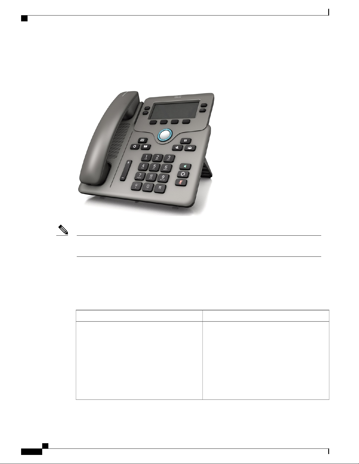
The Cisco IP Phone 6800 Series Multiplatform Phones comprises a set of full-featured VoIP
(Voice-over-Internet Protocol) phones that provide voice communication over an IP network. The phones
provide all the features of traditional business phones, such as call forwarding, redialing, speed dialing,
Cisco IP Phone 6800 Series Multiplatform Phones Administration Guide
3
Page 18
New and Changed Features
transferring calls, and conference calling. The Cisco IP Phone 6800 Series Multiplatform Phones is targeted
for solutions that are centered on Third-Party SIP-based IP PBX.
Figure 1: Cisco IP Phone 6800 Series Multiplatform Phone
Note
In this document, the terms Cisco IP Phone, phone, or device mean Cisco IP Phone 6800 Series
Multiplatform Phones.
New and Changed Features
New and Changed for Firmware Release 11.1(1)
Asian Language Support
New or Changed SectionsFeature
Dictionary Server Script, on page 58
Phone Display Problems, on page 217
The Font is Too Small or Has Unusual Characters,
on page 218
Phone Screen Displays Boxes Instead of Asian
Characters, on page 218
Phone Locale is Not Displayed, on page 219
Softkey Labels are Truncated, on page 218
Cisco IP Phone 6800 Series Multiplatform Phones Administration Guide
4
Page 19

Cisco IP Phone 6841 Multiplatform Phones Connections
New or Changed SectionsFeature
Call Center Support
Call Recording
Factory Reset Button in the Phone Web Page
IPv6 Support
Set Up a Call Center Agent Phone , on page 127
ACD Call Information Missing, on page 216
ACD Settings, on page 199
Phone Doesn't Show ACD Softkeys, on page 216
Enable Remote Call Recording with SIP REC, on
page 124
Enable Remote Call Recording with SIP INFO, on
page 126
Call Doesn't Record, on page 216
Factory Reset the Phone with the Web UI Button,
on page 222
Factory Reset, on page 147
Network Configuration Fields, on page 27Gigabit Support
Network Configuration Fields, on page 27
IPv6 Information, on page 141
Network Settings, on page 153
IPv6 Settings, on page 154
Presence
Set Up a Phone for Presence, on page 127
Presence Status Doesn't Work, on page 217
Phone Presence Message: Disconnected from Server,
on page 217
Broadsoft XMPP, on page 187
General, on page 182Wideband Handset Support
Cisco IP Phone 6841 Multiplatform Phones Connections
Connect your phone to your LAN with an Ethernet cable to enable full functionality of your phone. You need
to use a power adapter to power the phone. Do not extend the LAN Ethernet cable outside the building. For
your phone to work, it must be connected to the IP telephony network.
Cisco IP Phone 6800 Series Multiplatform Phones Administration Guide
5
Page 20

Cisco IP Phone 6851 Multiplatform Phones Connections
4DC adaptor port1
3
connection
Access port (10/100/1000 PC)
connection (optional)
Handset connection5Power adapter2
Analog headset connection (optional)6Network port (10/100/1000 SW)
Cisco IP Phone 6851 Multiplatform Phones Connections
Connect your phone to your LAN with an Ethernet cable to enable full functionality of your phone. If your
Ethernet port is equipped with Power over Ethernet (PoE), you can power the phone through the LAN port.
If you don't have PoE available, then you need to use a power adapter to power the phone. Do not extend the
LAN Ethernet cable outside the building. For your phone to work, it must be connected to the IP telephony
network.
Cisco IP Phone 6800 Series Multiplatform Phones Administration Guide
6
Page 21
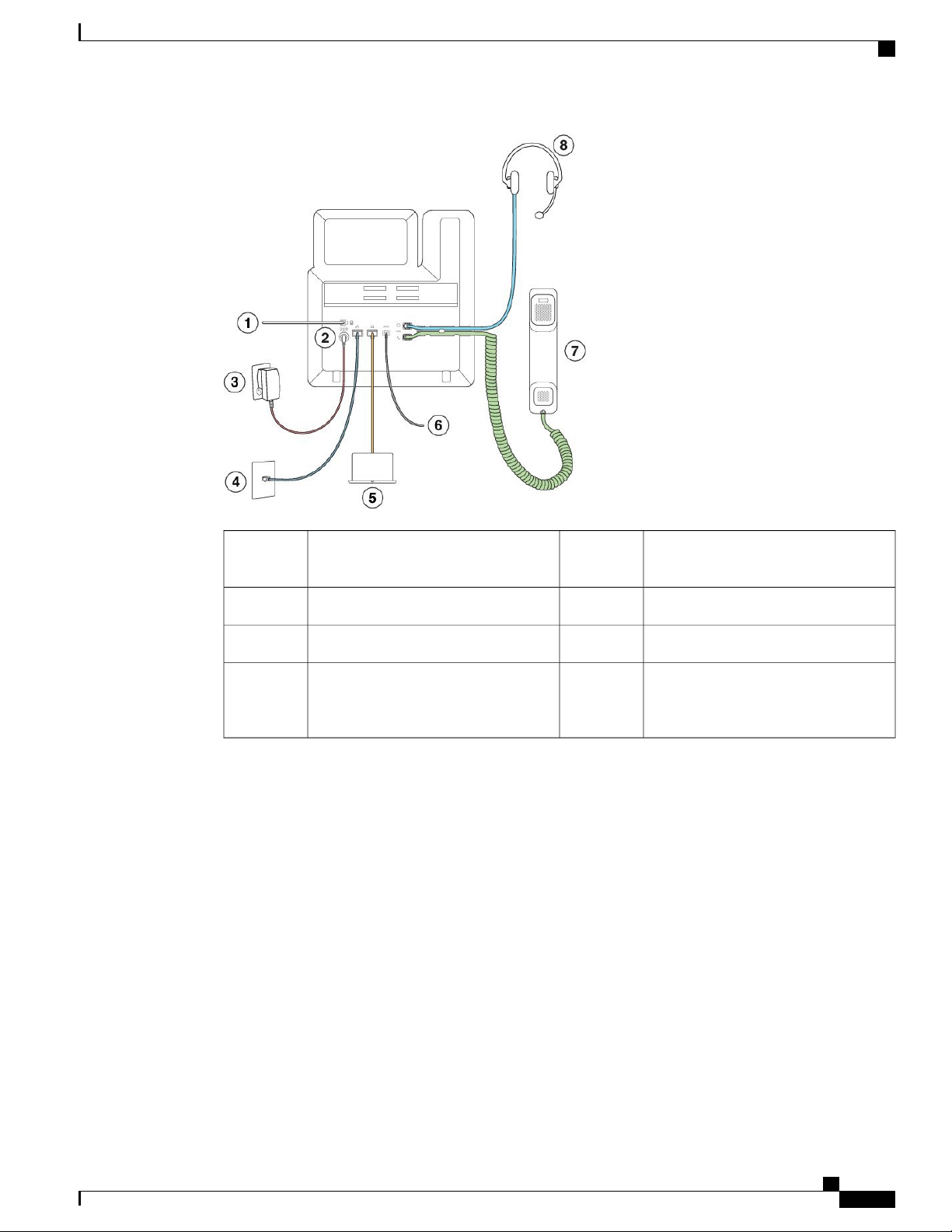
Cisco IP Phone 6851 Multiplatform Phones Connections
5For future use1
Access port (10/100/1000 PC)
connection (optional)
Auxiliary port (optional)6DC adaptor port (optional)2
Handset connection7Power adapter (optional)3
4
Analog headset connection (optional)8Network port (10/100/1000 SW)
connection; IEEE 802.3af power
enabled
Cisco IP Phone 6800 Series Multiplatform Phones Administration Guide
7
Page 22
Buttons and Hardware
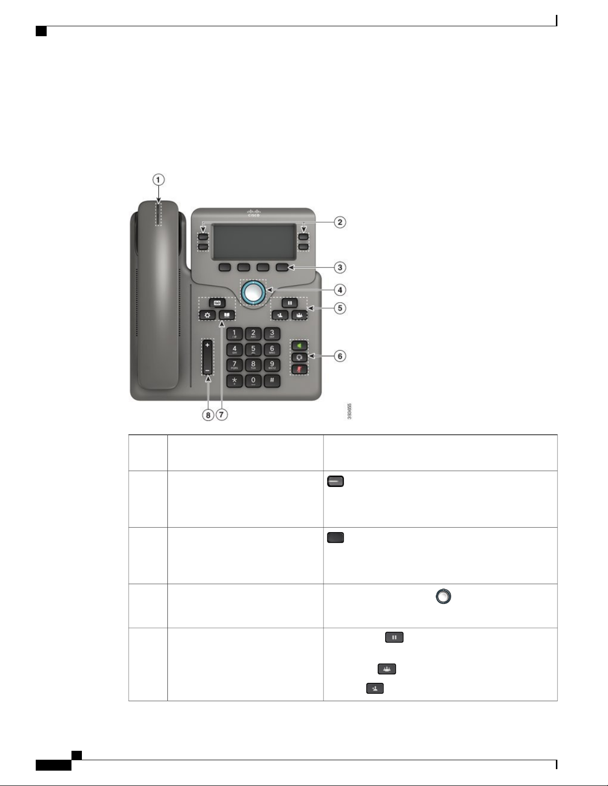
Buttons and Hardware
The following figure shows the Cisco IP Phone 6841.
Figure 2: Cisco IP Phone 6800 Series Buttons and Features
Handset and Handset light strip1
2
5
Programmable feature buttons and line
buttons
Softkey buttons3
Navigation cluster4
Hold/Resume, Conference, and
Transfer
Indicates whether you have an incoming call (flashing red)
or a new voice message (steady red).
Access your phone lines, features, and call sessions.
For more information, see Softkey, Line, and Feature
Buttons, on page 9.
Access functions and services.
For more information, see Softkey, Line, and Feature
Buttons, on page 9.
Navigation ring and Select button. Scroll through
menus, highlight items, and select the highlighted item.
Hold/Resume Place an active call on hold and resume
the held call.
Conference Create a conference call.
Transfer Transfer a call.
Cisco IP Phone 6800 Series Multiplatform Phones Administration Guide
8
Page 23

Buttons and Hardware
Speakerphone, Mute, and Headset6
Speakerphone Toggle the speakerphone on or off.
When the speakerphone is on, the button is lit.
Mute Toggle the microphone on or off. When the
microphone is muted, the button is lit.
Headset Toggle the headset on or off. When the
headset is on, the button is lit.
7
Contacts, Applications, and
Contacts Access personal and corporate directories.
Messages
Applications Access call history, user preferences,
phone settings, and phone model information.
Messages Autodial your voice messaging system.
Volume button8
Adjust the handset, headset, and speakerphone volume
(off hook) and the ringer volume (on hook).
Softkey, Line, and Feature Buttons
You can interact with the features on your phone in several ways:
Softkeys, located below the screen, give you access to the function displayed on the screen above the
•
softkey. The softkeys change depending on what you are doing at the time. The More ... softkey shows
you that more functions are available.
Feature and line buttons, located on either side of the screen, give you access to phone features and
•
phone lines.
◦ Feature buttons—Used for features such as Speed dial or Call pickup, and to view your status on
another line.
◦ Line buttons—Used to initiate or answer a call or resume a held call. You can also use a line key
to open and close the call session window, and to navigate through the call session window. Open
the call session window to see the calls on the line.
Feature and line buttons illuminate to indicate status:
•
Green—Line is idle.
•
Red, steady—Line is active or in use.
•
Red, flashing—Line is on hold or there is an inbound call.
•
Amber, steady—Line is unregistered (cannot be used).
Cisco IP Phone 6800 Series Multiplatform Phones Administration Guide
9
Page 24

Terminology Differences
Your administrator can set up some functions as softkeys or as feature buttons. You can also access some
functions with softkeys or the associated hard button.
Terminology Differences
The following table highlights some of the terminology differences in the Cisco IP Phone 6800 Series
Multiplatform Phones User Guide and the Cisco IP Phone 6800 Series Multiplatform Phones Administration
Guide
Table 1: Terminology Differences
Administration GuideUser Guide
Message Indicators
Message Waiting Indicator (MWI) or Message
Waiting Lamp
Voice Messaging SystemVoicemail System
Configuration UtilityPhone Web Page
Cisco IP Phone 6800 Series Multiplatform Phones Administration Guide
10
Page 25

CHAPTER 2
Technical Details
Physical and Operating Environment Specifications, page 11
•
Cable Specifications, page 12
•
Network and Computer Port Pinouts, page 12
•
Phone Power Requirements, page 14
•
Network Protocols, page 15
•
VLAN Interaction, page 18
•
External Devices, page 19
•
Physical and Operating Environment Specifications
The following table shows the physical and operating environment specifications for the Cisco IP Phone 6800
Series Multiplatform Phones.
Table 2: Physical and Operating Specifications
Value or RangeSpecification
32° to 104°F (0° to 40°C)Operating temperature
10% to 90% (noncondensing)Operating relative
humidity
Storage temperature
14° to 140°F (–10° to 60°C)
10% to 95% (noncondensing)Storage relative hunidity
8.14 in. (207 mm), excluding the footstandHeight
8.11 in. (206 mm)Width
1.1 in. (28 mm) , excluding the footstandDepth
Cisco IP Phone 6800 Series Multiplatform Phones Administration Guide
11
Page 26

Cable Specifications
Value or RangeSpecification
1.356 lb. (615 g), excluding footstand and handsetWeight
Power
Cables
Distance Requirements
For detailed technical information about the phone, see the datasheet at:
https://www.cisco.com/c/en/us/products/collaboration-endpoints/ip-phone-6800-series-multiplatform-firmware/
datasheet-listing.html
Cable Specifications
• 100-240 VAC, 50-60 Hz, 0.5 A—When using the AC adapter
• 48 VDC, 0.2 A—When using the in-line power over the network cable
Category 3/5/5e/6 for 10-Mbps cables with 4 pairs
•
Category 5/5e/6 for 100-Mbps cables with 4 pairs
•
Category 5/5e/6 for 1000-Mbps cables with 4 pairs
•
As supported by the Ethernet Specification, it is assumed that the maximum
cable length between each Cisco IP Phone and the switch is 100 meters (330
feet).
RJ-9 jack (4-conductor) for handset and headset connection.
•
RJ-45 jack for the LAN 10/100/1000BaseT connection.
•
RJ-45 jack for a second 10/100/1000BaseT connection.
•
5-volt power connector.
•
Network and Computer Port Pinouts
Although both the network and computer (access) ports are used for network connectivity, they serve different
purposes and have different port pinouts:
The network port is the 10/100/1000 SW port.
•
The computer (access) port is the 10/100/1000 PC port.
•
Network Port Connector
The following table describes the network port connector pinouts.
Cisco IP Phone 6800 Series Multiplatform Phones Administration Guide
12
Page 27

Table 3: Network Port Connector Pinouts
FunctionPin Number
BI_DA+1
BI_DA-2
BI_DB+3
BI_DC+4
BI_DC-5
BI_DB-6
BI_DD+7
BI_DD-8
Network and Computer Port Pinouts
Note
BI stands for bidirectional, while DA, DB, DC, and DD stand for Data A, Data B, Data C, and Data
D respectively.
Computer Port Connector
The following table describes the computer port connector pinouts.
Table 4: Computer (Access) Port Connector Pinouts
FunctionPin Number
BI_DB+1
BI_DB-2
BI_DA+3
BI_DD+4
BI_DD-5
BI_DA-6
Note
BI_DC+7
BI_DC-8
BI stands for bidirectional, while DA, DB, DC, and DD stand for Data A, Data B, Data C, and Data
D respectively.
Cisco IP Phone 6800 Series Multiplatform Phones Administration Guide
13
Page 28

Phone Power Requirements
Phone Power Requirements
The Cisco IP Phone 6841 is powered by external power. The Cisco IP Phone 6851 can be powered with
external power or with Power over Ethernet (PoE). A separate power supply provides external power. The
switch can provide PoE through the phone Ethernet cable.
Note
When you install a phone that is powered with external power, connect the power supply to the phone
and to a power outlet before you connect the Ethernet cable to the phone. When you remove a phone that
is powered with external power, disconnect the Ethernet cable from the phone before you disconnect the
power supply.
Table 5: Guidelines for Cisco IP Phone Power
GuidelinesPower Type
The Cisco IP Phone 6841 and 6851 use a custom power supply.External power: Provided
through the external power
supply
External power—Provided
through the Cisco IP Phone
Power Injector
The Cisco IP Phone Power Injector may be used with the Cisco IP Phone 6851.
Functioning as a midspan device, the injector delivers inline power to the
attached phone. The Cisco IP Phone Power Injector connects between a switch
port and the IP Phone, and supports a maximum cable length of 100m between
the unpowered switch and the IP phone.
PoE power—Provided by a
switch through the Ethernet
cable attached to the Cisco
IP Phone 6851.
To ensure uninterruptible operation of the phone, make sure that the switch
has a backup power supply.
Make sure that the CatOS or IOS version that runs on your switch supports
your intended phone deployment. See the documentation for your switch for
operating system version information.
The documents in the following table provide more information on the following topics:
Cisco switches that work with Cisco IP Phones
•
Cisco IOS releases that support bidirectional power negotiation
•
Other requirements and restrictions about power
•
URLDocument topics
PoE Solutions
http://www.cisco.com/c/en/us/solutions/enterprise-networks/
power-over-ethernet-solutions/index.html
Cisco Catalyst Switches
Cisco IP Phone 6800 Series Multiplatform Phones Administration Guide
14
http://www.cisco.com/c/en/us/products/switches/index.html
Page 29

Network Protocols
URLDocument topics
Integrated Service Routers
Cisco IOS Software
Network Protocols
Cisco IP Phones support several industry-standard and Cisco network protocols that are required for voice
communication. The following table provides an overview of the network protocols that the phones support.
Table 6: Supported Network Protocols on the Cisco IP Phone
Bootstrap Protocol (BootP)
Cisco Discovery Protocol
(CDP)
http://www.cisco.com/c/en/us/products/routers/index.html
http://www.cisco.com/c/en/us/products/ios-nx-os-software/
index.html
BootP enables a network device, such as
the Cisco IP Phone, to discover certain
startup information, such as its IP address.
CDP is a device-discovery protocol that
runs on all Cisco-manufactured
equipment.
A device can use CDP to advertise its
existence to other devices and receive
information about other devices in the
network.
Usage NotesPurposeNetwork Protocol
—
The Cisco IP Phone uses CDP to
communicate information such as
auxiliary VLAN ID, per port power
management details, and Quality of
Service (QoS) configuration
information with the Cisco Catalyst
switch.
Domain Name Server
(DNS)
Dynamic Host
Configuration Protocol
(DHCP)
Hypertext Transfer
Protocol (HTTP)
DNS translates domain names to IP
addresses.
DHCP dynamically allocates and assigns
an IP address to network devices.
DHCP enables you to connect an IP
phone into the network and have the
phone become operational without the
need to manually assign an IP address or
to configure additional network
parameters.
HTTP is the standard protocol for transfer
of information and movement of
documents across the Internet and the
web.
Cisco IP Phones have a DNS client
to translate domain names into IP
addresses.
DHCP is enabled by default. If
disabled, you must manually
configure the IP address, subnet
mask, and gateway on each phone
locally.
We recommend that you use the
DHCP custom option 160, 159.
Cisco IP Phones use HTTP for XML
services, provisioning, upgrade and
for troubleshooting purposes.
Cisco IP Phone 6800 Series Multiplatform Phones Administration Guide
15
Page 30

Network Protocols
Usage NotesPurposeNetwork Protocol
Hypertext Transfer
Protocol Secure (HTTPS)
Internet Protocol (IP)
Link Layer Discovery
Protocol (LLDP)
Hypertext Transfer Protocol Secure
(HTTPS) is a combination of the
Hypertext Transfer Protocol with the
SSL/TLS protocol to provide encryption
and secure identification of servers.
IP is a messaging protocol that addresses
and sends packets across the network.
LLDP is a standardized network
discovery protocol (similar to CDP) that
is supported on some Cisco and
third-party devices.
Web applications with both HTTP
and HTTPS support have two URLs
configured. Cisco IP Phones that
support HTTPS choose the HTTPS
URL.
A lock icon is displayed to the user
if the connection to the service is via
HTTPS.
To communicate with IP, network
devices must have an assigned IP
address, subnet, and gateway.
IP addresses, subnets, and gateways
identifications are automatically
assigned if you are using the Cisco
IP Phone with Dynamic Host
Configuration Protocol (DHCP). If
you are not using DHCP, you must
manually assign these properties to
each phone locally.
The Cisco IP Phone supports LLDP
on the PC port.
Link Layer Discovery
Protocol-Media Endpoint
Devices (LLDP-MED)
Network Transport
Protocol (NTP)
LLDP-MED is an extension of the LLDP
standard developed for voice products.
NTP is a networking protocol for clock
synchronization between computer
systems over packet-switched,
variable-latency data networks.
The Cisco IP Phone supports
LLDP-MED on the SW port to
communicate information such as:
Voice VLAN configuration
•
Device discovery
•
Power management
•
Inventory management
•
For more information about
LLDP-MED support, see the
LLDP-MED and Cisco Discovery
Protocol white paper at this URL:
http://www.cisco.com/en/US/tech/
tk652/tk701/technologies_white_
paper0900aecd804cd46d.shtml
Cisco IP Phones have an NTP client
integrated into the software.
Cisco IP Phone 6800 Series Multiplatform Phones Administration Guide
16
Page 31

Network Protocols
Usage NotesPurposeNetwork Protocol
Real-Time Transport
Protocol (RTP)
Real-Time Control
Protocol (RTCP)
Session Description
Protocol (SDP)
Session Initiation Protocol
(SIP)
RTP is a standard protocol for
transporting real-time data, such as
interactive voice and video, over data
networks.
provide QoS data (such as jitter, latency,
and round trip delay) on RTP streams.
SDP is the portion of the SIP protocol
that determines which parameters are
available during a connection between
two endpoints. Conferences are
established by using only the SDP
capabilities that all endpoints in the
conference support.
SIP is the Internet Engineering Task
Force (IETF) standard for multimedia
conferencing over IP. SIP is an
ASCII-based application-layer control
protocol (defined in RFC 3261) that can
be used to establish, maintain, and
terminate calls between two or more
endpoints.
Cisco IP Phones use the RTP
protocol to send and receive real-time
voice traffic from other phones and
gateways.
RTCP is disabled by default.RTCP works in conjunction with RTP to
SDP capabilities, such as codec
types, DTMF detection, and comfort
noise, are normally configured on a
global basis by a Third-Party Call
Control System or a Media Gateway
in operation. Some SIP endpoints
may allow configuration of these
parameters on the endpoint itself.
Like other VoIP protocols, SIP is
designed to address the functions of
signaling and session management
within a packet telephony network.
Signaling allows call information to
be carried across network boundaries.
Session management provides the
ability to control the attributes of an
end-to-end call.
Secure Real-Time Transfer
protocol (SRTP)
Transmission Control
Protocol (TCP)
Transport Layer Security
(TLS)
SRTP is an extension of the Real-Time
Protocol (RTP) Audio/Video Profile and
ensures the integrity of RTP and
Real-Time Control Protocol (RTCP)
packets providing authentication,
integrity, and encryption of media packets
between two endpoints.
TCP is a connection-oriented transport
protocol.
TLS is a standard protocol for securing
and authenticating communications.
Cisco IP Phones use SRTP for media
encryption.
—
When security is implemented, Cisco
IP Phones use the TLS protocol when
securely registering with the
third-party call control system.
Cisco IP Phone 6800 Series Multiplatform Phones Administration Guide
17
Page 32

VLAN Interaction
Usage NotesPurposeNetwork Protocol
Trivial File Transfer
Protocol (TFTP)
User Datagram Protocol
(UDP)
Related Topics
Verify the Network Setup, on page 23
Verify Phone Startup, on page 31
VLAN Interaction
The Cisco IP Phone contains an internal Ethernet switch, enabling forwarding of packets to the phone, and
to the computer (access) port and the network port on the back of the phone.
If a computer is connected to the computer (access) port, the computer and the phone share the same physical
link to the switch and share the same port on the switch. This shared physical link has the following implications
for the VLAN configuration on the network:
TFTP allows you to transfer files over the
network.
On the Cisco IP Phone, TFTP enables
you to obtain a configuration file specific
to the phone type.
UDP is a connectionless messaging
protocol for delivery of data packets.
TFTP requires a TFTP server in your
network, which can be automatically
identified from the DHCP server.
UDP is used only for RTP streams.
SIP uses UDP, TCP, and TLS.
The current VLANs might be configured on an IP subnet basis. However, additional IP addresses might
•
not be available to assign the phone to the same subnet as other devices that connect to the same port.
Data traffic present on the VLAN supporting phones might reduce the quality of VoIP traffic.
•
Network security may indicate a need to isolate the VLAN voice traffic from the VLAN data traffic.
•
You can resolve these issues by isolating the voice traffic onto a separate VLAN. The switch port to which
the phone connects would be configured for separate VLANs for carrying:
Voice traffic to and from the IP phone (auxiliary VLAN on the Cisco Catalyst 6000 series, for example)
•
Data traffic to and from the PC that connects to the switch through the computer (access) port of the IP
•
phone (native VLAN)
Isolating the phones on a separate, auxiliary VLAN increases the quality of the voice traffic and allows a large
number of phones to be added to an existing network that does not have enough IP addresses for each phone.
For more information, see the documentation that is included with a Cisco switch. You can also access switch
information at this URL:
http://cisco.com/en/US/products/hw/switches/index.html
Cisco IP Phone 6800 Series Multiplatform Phones Administration Guide
18
Page 33

External Devices
We recommend that you use good-quality external devices that are shielded against unwanted radio frequency
(RF) and audio frequency (AF) signals. External devices include headsets, cables, and connectors.
Depending on the quality of these devices and their proximity to other devices, such as mobile phones or
two-way radios, some audio noise may still occur. In these cases, we recommend that you take one or more
of these actions:
Cisco cannot guarantee the performance of external devices, cables, and connectors.
External Devices
Move the external device away from the source of the RF or AF signals.
•
Route the external device cables away from the source of the RF or AF signals.
•
Use shielded cables for the external device, or use cables with a better shield and connector.
•
Shorten the length of the external device cable.
•
Apply ferrites or other such devices on the cables for the external device.
•
Caution
In European Union countries, use only external speakers, microphones, and headsets that are fully compliant
with the EMC Directive [89/336/EC].
Cisco IP Phone 6800 Series Multiplatform Phones Administration Guide
19
Page 34

External Devices
Cisco IP Phone 6800 Series Multiplatform Phones Administration Guide
20
Page 35

PART II
Phone Installation
Cisco IP Phone Installation, page 23
•
Third Party Call Control Setup, page 61
•
Page 36

Page 37

CHAPTER 3
Cisco IP Phone Installation
Verify the Network Setup, page 23
•
Install the Cisco IP Phone, page 24
•
Configure the Network from the Phone, page 25
•
Verify Phone Startup, page 31
•
Configure the Voice Codecs, page 31
•
Set the Optional Network Servers, page 32
•
VLAN Settings, page 32
•
SIP and NAT Configuration, page 39
•
Dial Plan, page 48
•
Regional Parameters and Supplementary Services, page 54
•
Cisco IP Phone 6800 Series Documentation, page 59
•
Verify the Network Setup
Upon deployment of a new IP telephony system, system administrators and network administrators must
complete several initial configuration tasks to prepare the network for IP telephony service.
For the phone to operate successfully as an endpoint in your network, your network must meet specific
requirements.
Note
Step 1
The phone displays the date and time from Third-Party Call Control. The time displayed on the phone
can differ from the Third-Party Call Control time by up to 10 seconds.
Procedure
Configure a VoIP Network to meet the following requirements:
Cisco IP Phone 6800 Series Multiplatform Phones Administration Guide
23
Page 38

Install the Cisco IP Phone
VoIP is configured on your Cisco routers and gateways.
•
Third-Party Call Control is installed in your network and is configured to handle call processing.
•
Step 2
Set up the network to support one of the following:
DHCP support
•
Manual assignment of IP address, gateway, and subnet mask
•
Install the Cisco IP Phone
After the phone connects to the network, the phone startup process begins, and the phone registers with the
Third-Party Call Control System. To finish phone installation, you need to configure the network settings on
the phone either manually or with DHCP.
Before using external devices, read External Devices, on page 19.Note
If you only have one LAN cable at your desk, you can plug your phone into the LAN with the SW port and
then connect your computer into the PC port.
You can also daisy chain two phones together. Connect the PC port of the first phone to the SW port of the
second phone.
Step 1
Step 2
Step 3
Step 4
Do not connect the SW and PC ports into the LAN.Caution
Procedure
Choose the power source for the phone:
• Power over Ethernet (PoE)—Cisco IP Phone 6851 Multiplatform Phones only
External power supply
•
For more information, see Phone Power Requirements, on page 14.
Connect the handset to the handset port.
The phone ships with a narrowband handset. You can buy a wideband-capable handset that is designed
especially for use with the phone.
The handset includes a light strip that indicates incoming calls and waiting voice messages.
Connect a headset to the headset port. You can add a headset later if you do not connect one now.
Connect a straight-through Ethernet cable from the switch to the network port labeled 10/100/1000 SW on
the phone. Each phone ships with one Ethernet cable in the box.
Cisco IP Phone 6800 Series Multiplatform Phones Administration Guide
24
Page 39

Configure the Network from the Phone
Use Category 3, 5, 5e, or 6 cabling for 10 Mbps connections; Category 5, 5e, or 6 for 100 Mbps connections;
and Category 5e or 6 for 1000 Mbps connections. For more information, see Network and Computer Port
Pinouts, on page 12.
Step 5
Step 6
Step 7
Step 8
Step 9
Step 10
Step 11
Connect a straight-through Ethernet cable from another network device, such as a desktop computer, to the
computer port on the phone. You can connect another network device later if you do not connect one now.
Use Category 3, 5, 5e, or 6 cabling for 10 Mbps connections; Category 5, 5e, or 6 for 100 Mbps connections;
and Category 5e or 6 for 1000 Mbps connections. For more information, see Network and Computer Port
Pinouts, on page 12 for guidelines.
If the phone is wall-mounted, you might need to adjust the handset rest to ensure that the receiver cannot slip
out of the cradle. For more information, see Adjust the Handset Rest, on page 75.
Monitor the phone startup process. This step verifies that the phone is configured properly.
Use DHCP or manually enter an IP address for the phone.
See Configure the Network from the Phone, on page 25.
Upgrade the phone to the current firmware image.
Firmware upgrades over the WLAN interface may take longer than upgrading over the wired interface,
depending on the quality and bandwidth of the wireless connection. Some upgrades may take more than one
hour.
Make calls with the phone to verify that the phone and features work correctly.
See the Cisco IP Phone 6800 Series Multiplatform Phones User Guide.
Provide information to end users about how to use their phones and how to configure their phone options.
This step ensures that users have adequate information to successfully use their phones.
Configure the Network from the Phone
The phone includes many configurable network settings that you may need to modify before it is functional
for your users. You can access these setting through the phone menus.
The Network configuration menu provides you with options to view and configure a variety of network
settings.
Cisco IP Phone 6800 Series Multiplatform Phones Administration Guide
25
Page 40

Configure the Network from the Phone
Note
Step 1
Step 2
Step 3
Step 4
Step 5
You can control whether a phone has access to the Settings menu or to options on this menu by modifying
the value in the Phone-UI-User-Mode field in the Voice > System > System Configuration section of
the Phone Configuration Utility page. Also, you must modify the attribute of ua in the Resync file of the
phone to control the access. For example, when Phone-UI_User_mode is set to Yes and in the resync file
the attribute for Speed_Dial_2 are:
Speed_Dial_2 ua="rw", you can read and write on web of user model and lcd.
•
Speed_Dial_2 ua="na", you can only read on web of user model and lcd.
•
The Phone-UI-User-Mode field accepts these values:
Yes: Allows access to the Settings menu. It also allows access to the Phone Configuration Utility
•
page for user-mode.
No: Prevents access to the Settings menu. It also restricts access to the Phone Configuration Utility
•
page for user-mode.
If you cannot access an option on the Admin Settings menu, check the Phone-UI-User-Mode field.
You can configure settings that are display-only on the phone in your Third-Party Call Control system.
Procedure
Press Applications .
Select Network configuration.
Use the navigation arrows to select the desired menu and edit.
To display a submenu, repeat step 3.
To exit a menu, press .
Cisco IP Phone 6800 Series Multiplatform Phones Administration Guide
26
Page 41

Network Configuration Fields
Table 7: Ethernet Configuration Submenu
Configure the Network from the Phone
Field
802.1x
authentication
Switch port config
or Choices
authentication
10MB half
10MB full
100 MB half
100MB full
100 half
1000 full
DescriptionDefaultField Type
OffDevice
Enables you to turn 802.1x authentication on or turn it off. Valid
options are:
On
•
Off
•
DisabledTransaction status
• Transaction status—Indicates different authentication status
when you turn on 802.1x in the Device authentication field.
◦ Disabled—This is default status.
◦ Connecting—Indicates 802.1x authentication is
initiated in the device.
◦ Authenticated—Indicates 802.1x authentication is
established in the device.
• Protocol—Specifies the protocol of the server.
AutoAuto
Allows you to select speed and duplex of the network port.
If the phone is connected to a switch, configure the port on the
switch to the same speed/duplex as the phone, or configure both
to autonegotiate.
If you change the setting of this option, you must change the PC
Port config option to the same setting.
PC port config
10MB half
10MB full
100 MB half
100MB full
100 half
1000 full
AutoAuto
Allows you to select Speed and duplex of the Computer (access)
port.
If the phone is connected to a switch, configure the port on the
switch to the same speed/duplex as the phone, or configure both
to autonegotiate.
If you change the setting of this option, you must change the
Switch Port config option to the same setting.
Cisco IP Phone 6800 Series Multiplatform Phones Administration Guide
27
Page 42

Configure the Network from the Phone
Field
CDP
LLDP-MED
VLAN
or Choices
Off
Off
Off
DescriptionDefaultField Type
OnOn
Allows you to enable or disable Cisco Discovery Protocol (CDP).
CDP is a device-discovery protocol that runs on all Cisco
manufactured equipment.
Using CDP, a device can advertise its existence to other devices
and receive information about other devices in the network.
OnOn
Allows you to enable or disable LLDP-MED.
LLDAP-MED enables the phone to advertise itself to devices
that use the discovery protocol.
3 secondsStartup delay
Allows you to set a value that causes a delay for the switch to get
to the forwarding state before the phone will send out the first
LLDP-MED packet. The default delay is 3 seconds. For
configuration of some switches, you might need to increase this
value to a higher value for LLDP-MED to work. Configuring a
delay can be important for networks that use the Spanning Tree
Protocol.
OffOn
Allows you to enable or disable VLAN.
Allows you to enter a VLAN ID when you use VLAN without
CDP or LLDP. When you use a VLAN with CDP or LLDP, that
associated VLAN takes precedent over the manual entered VLAN
ID.
VLAN ID
PC port VLAN ID
PC port mirror
you need to enter
values
you need to enter
values
Off
1Text fields in which
Allows you to enter a VLAN ID for the IP phone when you use
a VLAN without CDP (VLAN enabled and CDP disabled). Note
that only voice packets are tagged with the VLAN ID. Do not
use 1 for the VLAN ID. If VLAN ID is 1, you cannot tag voice
packets with the VLAN ID.
1Text fields in which
Value of the VLAN ID that is used to tag communications from
the PC port on the phone.
The phone tags all the untagged frames coming from the PC (it
will not tag frames with an existing tag).
Valid values are: 0-4095. Default: 0.
OnOn
Adds the ability to port mirror on the PC port. When enabled,
you can see the packets on the phone. Select On to enable PC
port mirroring and select No to disable it.
Cisco IP Phone 6800 Series Multiplatform Phones Administration Guide
28
Page 43

Table 8: IPv4 Address Settings Submenu
Configure the Network from the Phone
Field
or Choices
DHCPConnection type
Static IP
DescriptionDefaultField Type
Indicates whether the phone has DHCP enabled.
• DNS1—Identifies the primary Domain Name System (DNS)
server that the phone uses.
• DNS2—Identifies the secondary Domain Name System
(DNS) server that the phone uses.
• DHCP address released—Releases the IP address that DHCP
assigned. This field is editable if DHCP is enabled. If you
wish to remove the phone from the VLAN and release the
IP address for reassignment, set this field to Yes and press
Set.
When DHCP is disabled, you must set the Internet Protocol (IP)
address of the phone.
• Static IP address—Identifies the IP that you assign to the
phone. The phone uses this IP address instead of acquiring
an IP from the DHCP server on the network.
• Subnet Mask—Identifies the subnet mask used by the phone.
When DHCP is disabled, you must set the subnet mask.
• Gateway address—Identifies the default router used by the
phone.
• DNS1—Identifies the primary Domain Name System (DNS)
server that the phone uses. When DHCP is disabled, you
must set this field manually.
• DNS2—Identifies the primary Domain Name System (DNS)
server that the phone uses. When DHCP is disabled, you
must set this field manually.
If you assign an IP address with this field, you must also assign
a subnet mask and a gateway address. See the Subnet Mask and
Default Router fields in this table.
Cisco IP Phone 6800 Series Multiplatform Phones Administration Guide
29
Page 44

Configure the Network from the Phone
Table 9: IPv6 Address Settings Submenu
Field
or Choices
DHCPConnection type
Static IP
DescriptionDefaultField Type
Indicates whether the phone has Dynamic Host Configuration
Protocol (DHCP) enabled.
• DNS1—Identifies the primary DNS server that the phone
uses.
• DNS2—Identifies the secondary DNS server that the phone
uses.
• Broadcast Echo—Identifies if the phone responses to
multicast ICMPv6 message with destination address of
ff02::1.
• Auto config— Identifies if the phone uses automatic
configuration for the address.
When DHCP is disabled, you must set the Internet Protocol (IP)
address of the phone and must set the values of the fields:
• Static IP—Identifies the IP that you assign to the phone.
The phone uses this IP address instead of acquiring an IP
from the DHCP server on the network.
• Prefix length—Identifies how many bits of a Global Unicast
IPv6 Address are there in network part.
Text and Menu Entry From the Phone
When you edit the value of an option setting, follow these guidelines:
Use the arrows on the navigation pad to highlight the field that you wish to edit. Press Select in the
•
navigation pad to activate the field. After the field is activated, you can enter values.
Use the keys on the keypad to enter numbers and letters.
•
• Gateway—Identifies the default router used by the phone.
• Primary DNS—Identifies the primary DNS server that the
phone uses. When DHCP is disabled, you must set this field
manually.
• Secondary DNS—Identifies the primary DNS server that
the phone uses. When DHCP is disabled, you must set this
field manually.
• Broadcast Echo—Identifies if the phone responses to
multicast ICMPv6 message with destination address of
ff02::1.
Cisco IP Phone 6800 Series Multiplatform Phones Administration Guide
30
Page 45

To enter letters by using the keypad, use a corresponding number key. Press the key one or more times
•
to display a particular letter. For example, press the 2 key once for “a,” twice quickly for “b,” and three
times quickly for “c.” After you pause, the cursor automatically advances to allow you to enter the next
letter.
Press the softkey if you make a mistake. This softkey deletes the character to the left of the cursor.
•
Press Back before pressing Set to discard any changes that you made.
•
To enter a period (for example, in an IP address), press * on the keypad.
•
The Cisco IP Phone provides several methods to reset or restore option settings, if necessary.Note
Verify Phone Startup
After the Cisco IP Phone has power connected to it, the phone automatically cycles through a startup diagnostic
process.
Verify Phone Startup
Procedure
Step 1
Step 2
If you are using Power over Ethernet, plug the LAN cable into the Network port.
If you are using the power cube, connect the cube to the phone and plug the cube into an electrical outlet.
The buttons flash amber and then green in sequence during the various stages of bootup as the phone checks
the hardware.
If the phone completes these stages successfully, it has started up properly.
Configure the Voice Codecs
A codec resource is considered allocated if it has been included in the SDP codec list of an active call, even
though it eventually might not be chosen for the connection. Negotiation of the optimal voice codec sometimes
depends on the ability of the Cisco IP Phone to match a codec name with the far-end device or gateway codec
name. The phone allows the network administrator to individually name the various codecs that are supported
such that the correct codec successfully negotiates with the far-end equipment.
The Cisco IP Phone supports voice codec priority. You can select up to three preferred codecs. The administrator
can select the low-bit-rate codec that is used for each line. G.711a and G.711u are always enabled.
Cisco IP Phone 6800 Series Multiplatform Phones Administration Guide
31
Page 46

Set the Optional Network Servers
Procedure
Step 1
Step 2
Step 3
To configure the voice codecs on each extension, in the phone web user interface, navigate to Admin Login
> advanced > Voice > Ext(n), where n is an extension number.
In the Audio Configuration section, configure the parameters.
Click Submit All Changes.
Set the Optional Network Servers
Optional network servers provide resources such as DNS lookup, network time, logging, and device discovery.
It also enables you to add PC port mirroring on the user phone. Your user can also enable or disable this
service from the phone.
Procedure
Step 1
Step 2
Step 3
In the phone web page, navigate to Admin Login > advanced > Voice > System.
In the Optional Network Configuration section, set up the fields as described in Optional Network
Configuration, on page 155.
Click Submit All Changes.
VLAN Settings
If you use a virtual LAN (VLAN), your phone voice packets are tagged with the VLAN ID.
In the VLAN Settings section of the Voice > System window, you can configure these settings:
Cisco Discovery Protocol
Cisco Discovery Protocol (CDP) is negotiation-based and determines which virtual LAN (VLAN) the Cisco
IP Phone resides in. If you are using a Cisco switch, Cisco Discovery Protocol (CDP) is available and is
enabled by default. CDP has these attributes:
Cisco Discovery Protocol (CDP)
•
LLDP-MED
•
Network Startup Delay
•
VLAN ID
•
Obtains the protocol addresses of neighboring devices and discovers the platform of those devices.
•
Shows information about the interfaces your router uses.
•
Cisco IP Phone 6800 Series Multiplatform Phones Administration Guide
32
Page 47

LLDP-MED
VLAN Settings
Is media and protocol-independent.
•
If you are using a VLAN without CDP, you must enter a VLAN ID for the Cisco IP Phone.
The Cisco IP Phone supports Link Layer Discovery Protocol for Media Endpoint Devices (LLDP-MED) for
deployment with Cisco or other Third-Party network connectivity devices that use a Layer 2 auto discovery
mechanism. Implementation of LLDP-MED is done in accordance with IEEE 802.1AB (LLDP) Specification
of May 2005, and ANSI TIA-1057 of April 2006.
The Cisco IP Phone operates as a LLDP-MED Media End Point Class III device with direct LLDP-MED
links to Network Connectivity Devices, according to the Media Endpoint Discovery Reference Model and
Definition (ANSI TIA-1057 Section 6).
The Cisco IP Phone supports only the following limited set of Type-Length-Values (TLV) as an LLDP-MED
Media Endpoint device class III:
Chassis ID TLV
•
Port ID TLV
•
Time to live TLV
•
Port Description TLV
•
System Name TLV
•
System Capabilities TLV
•
IEEE 802.3 MAC/PHY Configuration/Status TLV (for wired network only)
•
LLDP-MED Capabilities TLV
•
LLDP-MED Network Policy TLV (for application type=Voice only)
•
LLDP-MED Extended Power-Via-MDI TLV (for wired network only)
•
LLDP-MED Firmware Revision TLV
•
End of LLDPDU TLV
•
The outgoing LLDPDU contains all the preceding TLVs if applicable. For the incoming LLDPDU, the
LLDPDU is discarded if any of the following TLVs are missing. All other TLVs are not validated and ignored.
Chassis ID TLV
•
Port ID TLV
•
Time to live TLV
•
LLDP-MED Capabilities TLV
•
LLDP-MED Network Policy TLV (for application type=Voice only)
•
End of LLDPDU TLV
•
The Cisco IP Phone sends out the shutdown LLDPDU if applicable. The LLDPDU frame contains the following
TLVs:
Cisco IP Phone 6800 Series Multiplatform Phones Administration Guide
33
Page 48

VLAN Settings
Chassis ID TLV
Chassis ID TLV
•
Port ID TLV
•
Time to live TLV
•
End of LLDPDU TLV
•
There are some restrictions in the implementation of LLDP-MED on the Cisco IP Phones:
Storage and retrieval of neighbor information are not supported.
•
SNMP and corresponding MIBs are not supported.
•
Recording and retrieval of statistical counters are not supported.
•
Full validation of all TLVs does not take place; TLVs that do not apply to the phones are ignored.
•
Protocol state machines as stated in the standards are used only for reference.
•
For the outgoing LLDPDU, the TLV supports subtype=5 (Network Address). When the IP address is known,
the value of the Chassis ID is an octet of the INAN address family number followed by the octet string for
the IPv4 address used for voice communication. If the IP address is unknown, the value for the Chassis ID is
0.0.0.0. The only INAN address family supported is IPv4. Currently, the IPv6 address for the Chassis ID is
not supported.
For the incoming LLDPDU, the Chassis ID is treated as an opaque value to form the MSAP identifier. The
value is not validated against its subtype.
The Chassis ID TLV is mandatory as the first TLV. Only one Chassis ID TLV is allowed for the outgoing
and incoming LLDPDUs.
Port ID TLV
Time to Live TLV
For the outgoing LLDPDU, the TLV supports subtype=3 (MAC address). The 6 octet MAC address for the
Ethernet port is used for the value of Port ID.
For the incoming LLDPDU, the Port ID TLV is treated as an opaque value to form the MSAP identifier. The
value is not validated against its subtype.
The Port ID TLV is mandatory as the second TLV. Only one Port ID TLV is allowed for the outgoing and
incoming LLDPDUs.
For the outgoing LLDPDU, the Time to Live TTL value is 180 seconds. This differs from the 120-second
value that the standard recommends. For the shutdown LLDPDU, the TTL value is always 0.
The Time to Live TLV is mandatory as the third TLV. Only one Time to Live TLV is allowed for the outgoing
and incoming LLDPDUs.
Cisco IP Phone 6800 Series Multiplatform Phones Administration Guide
34
Page 49

End of LLDPDU TLV
The value is 2-octet, all zero. This TLV is mandatory and only one is allowed for the outgoing and incoming
LLDPDUs.
Port Description TLV
For the outgoing LLDPDU, in the Port Description TLV, the value for the port description is the same as
“Port ID TLV” for CDP. The incoming LLDPDU, the Port Description TLV, is ignored and not validated.
Only one Port Description TLV is allowed for outgoing and incoming LLDPDUs.
System Name TLV
For the Cisco IP Phone, the value is SEP+MAC address.
Example: SEPAC44F211B1D0
The incoming LLDPDU, the System Name TLV, is ignored and not validated. Only one System Name TLV
is allowed for the outgoing and incoming LLDPDUs.
VLAN Settings
System Capabilities TLV
For the outgoing LLDPDU, in the System Capabilities TLV, the bit values for the 2 octet system capabilities
fields should be set for Bit 2 (Bridge) and Bit 5 (Phone) for a phone with a PC port. If the phone does not
have a PC port, only Bit 5 should be set. The same system capability value should be set for the enabled
capability field.
For the incoming LLDPDU, the System Capabilities TLV is ignored. The TLV is not validated semantically
against the MED device type.
The System Capabilities TLV is mandatory for outgoing LLDPDUs. Only one System Capabilities TLV is
allowed.
Management Address TLV
The TLV identifies an address associated with the local LLDP agent (that may be used to reach higher layer
entities) to assist discovery by network management. The TLV allows the inclusion of both the system interface
number and an object identifier (OID) that are associated with this management address, if either or both are
known.
• TLV information string length—This field contains the length (in octets) of all the fields in the TLV
information string.
• Management address string length—This field contains the length (in octets) of the management address
subtype + management address fields.
System Description TLV
The TLV allows the network management to advertise the system description.
• TLV information string length—This field indicates the exact length (in octets) of the system description.
Cisco IP Phone 6800 Series Multiplatform Phones Administration Guide
35
Page 50

VLAN Settings
• System description—This field contains an alphanumeric string that is the textual description of the
network entity. The system description includes the full name and version identification of the system
hardware type, software operating system, and networking software. If implementations support IETF
RFC 3418, the sysDescr object should be used for this field.
IEEE 802.3 MAC/PHY Configuration/Status TLV
The TLV is not for autonegotiation, but for troubleshooting purposes. For the incoming LLDPDU, the TLV
is ignored and not validated. For the outgoing LLDPDU, for the TLV, the octet value autonegotiation
support/status should be:
• Bit 0—Set to 1 to indicate that the autonegotiation support feature is supported.
• Bit 1—Set to 1 to indicate that autonegotiation status is enabled.
• Bit 2-7—Set to 0.
The bit values for the 2 octets PMD autonegotiation advertised capability field should be set to:
• Bit 13—10BASE-T half duplex mode
• Bit 14—10BASE-T full duplex mode
• Bit 11—100BASE-TX half duplex mode
• Bit 10—100BASE-TX full duplex mode
• Bit 15—Unknown
Bit 10, 11, 13 and 14 should be set.
The value for 2 octets operational MAU type should be set to reflect the real operational MAU type:
• 16—100BASE-TX full duplex
• 15—100BASE-TX half duplex
• 11—10BASE-T full duplex
• 10—10BASE-T half duplex
For example, usually, the phone is set to 100BASE-TX full duplex. The value 16 should then be set. The TLV
is optional for a wired network and not applicable for a wireless network. The phone sends out this TLV only
when in wired mode. When the phone is not set for autonegotiation but specific speed/duplexity, for the
outgoing LLDPDU TLV, bit 1 for the octet value autonegotiation support/status should be clear (0) to indicate
that autonegotiation is disabled. The 2 octets PMD autonegotiation advertised capability field should be set
to 0x8000 to indicate unknown.
LLDP-MED Capabilities TLV
For the outgoing LLDPDU, the TLV should have the device type 3 (End Point Class III) with the following
bits set for 2-octet Capability field:
Cisco IP Phone 6800 Series Multiplatform Phones Administration Guide
36
CapabilityBit Position
LLDP-MED Capabilities0
Page 51

For the incoming TLV, if the LLDP-MED TLV is not present, the LLDPDU is discarded. The LLDP-MED
Capabilities TLV is mandatory and only one is allowed for the outgoing and incoming LLDPDUs. Any other
LLDP-MED TLVs will be ignored if they present before the LLDP-MED Capabilities TLV.
Network Policy TLV
In the TLV for the outgoing LLDPDU, before the VLAN or DSCP is determined, the Unknown Policy Flag
(U) is set to 1. If the VLAN setting or DSCP is known, the value is set to 0. When the policy is unknown, all
other values are set to 0. Before the VLAN is determined or used, the Tagged Flag (T) is set to 0. If the tagged
VLAN (VLAN ID > 1) is used for the phone, the Tagged Flag (T) is set to 1. Reserved (X) is always set to
0. If the VLAN is used, the corresponding VLAN ID and L2 Priority will be set accordingly. VLAN ID valid
value is range from 1-4094. However, VLAN ID=1 will never be used (limitation). If DSCP is used, the value
range from 0-63 is set accordingly.
In the TLV for the incoming LLDPDU, Multiple Network Policy TLVs for different application types are
allowed.
VLAN Settings
CapabilityBit Position
Network Policy1
Extended Power via MDI-PD4
Inventory5
LLDP-MED Extended Power-Via-MDI TLV
In the TLV for the outgoing LLDPDU, the binary value for Power Type is set to “0 1” to indicate the power
type for phone is PD Device. The Power source for the phone is set to “PSE and local” with binary value “1
1”. The Power Priority is set to binary “0 0 0 0” to indicate unknown priority while the Power Value is set to
maximum power value. The Power Value for the Cisco IP Phone is 12900mW.
For the incoming LLDPDU, the TLV is ignored and not validated. Only one TLV is allowed in the outgoing
and incoming LLDPDUs. The phone will send out the TLV for the wired network only.
The LLDP-MED standard was originally drafted in the context of Ethernet. Discussion is ongoing for
LLDP-MED for Wireless Networks. Refer to ANSI-TIA 1057, Annex C, C.3 Applicable TLV for VoWLAN,
table 24. It is recommended that the TLV is not applicable in the context of the wireless network. This TLV
is targeted for use in the context of PoE and Ethernet. The TLV, if added, will not provide any value for
network management or power policy adjustment at the switch.
LLDP-MED Inventory Management TLV
This TLV is optional for Device Class III. For the outgoing LLDPDU, we support only Firmware Revision
TLV. The value for the Firmware Revision is the version of firmware on the phone. For the incoming LLDPDU,
the TLVs are ignored and not validated. Only one Firmware Revision TLV is allowed for the outgoing and
incoming LLDPDUs.
Cisco IP Phone 6800 Series Multiplatform Phones Administration Guide
37
Page 52

VLAN Settings
Final Network Policy Resolution and QoS
Special VLANs
VLAN=0, VLAN=1, and VLAN=4095 are treated the same way as an untagged VLAN. Because the VLAN
is untagged, Class of Service (CoS) is not applicable.
Default QoS for SIP Mode
If there is no network policy from CDP or LLDP-MED, the default network policy is used. CoS is based on
configuration for the specific extension. It is applicable only if the manual VLAN is enabled and manual
VLAN ID is not equal to 0, 1, or 4095. Type of Service (ToS) is based on configuration for the specific
extension.
QoS Resolution for CDP
If there is a valid network policy from CDP:
If the VLAN=0, 1, or 4095, the VLAN will not be set, or the VLAN is untagged. CoS is not applicable,
•
but DSCP is applicable. ToS is based on the default as previously described.
If the VLAN > 1 and VLAN < 4095, the VLAN is set accordingly. CoS and ToS are based on the default
•
as previously described. DSCP is applicable.
The phone reboots and restarts the fast start sequence.
•
QoS Resolution for LLDP-MED
If CoS is applicable and if CoS = 0, the default is used for the specific extension as previously described. But
the value shown on L2 Priority for TLV for outgoing LLDPDU is based on the value used for extension 1. If
CoS is applicable and if CoS != 0, CoS is used for all extensions.
If DSCP (mapped to ToS) is applicable and if DSCP = 0, the default is used for the specific extension as
previously described. But the value show on DSCP for TLV for outgoing LLDPDU is based on value used
for the extension 1. If DSCP is applicable and if DSCP != 0, DSCP is used for all extensions.
If the VLAN > 1 and VLAN < 4095, the VLAN is set accordingly. CoS and ToS are based on the default as
previously described. DSCP is applicable.
If there is a valid network policy for the voice application from LLDP-MED PDU and if the tagged flag is
set, the VLAN, L2 Priority (CoS), and DSCP (mapped to ToS) are all applicable.
If there is a valid network policy for the voice application from LLDP-MED PDU and if the tagged flag is
not set, only the DSCP (mapped to ToS) is applicable.
The Cisco IP Phone reboots and restarts the fast start sequence.
Coexistence with CDP
Cisco IP Phone 6800 Series Multiplatform Phones Administration Guide
38
If both CDP and LLDP-MED are enabled, the network policy for the VLAN determines the last policy set or
changed with either one of the discovery modes. If both LLDP-MED and CDP are enabled, during startup
the phone sends CDP and LLDP-MED PDUs.
Page 53

Inconsistent configuration and behavior for network connectivity devices for CDP and LLDP-MED modes
could result in an oscillating rebooting behavior for the phone due to switching to different VLANs.
If the VLAN is not set by CDP and LLDP-MED, the VLAN ID that is configured manually is used. If the
VLAN ID is not configured manually, no VLAN is supported. DSCP is used and the network policy determines
LLDP-MED if applicable.
LLDP-MED and Multiple Network Devices
You can use the same application type for network policy. However, phones receive different Layer 2 or Layer
3 QoS Network policies from multiple network connectivity devices. In such a case, the last valid network
policy is accepted.
Configure VLAN Settings
Procedure
SIP and NAT Configuration
Step 1
Step 2
Step 3
In the phone web user interface, navigate to Admin Login > advanced > Voice > System.
In the VLAN Settings section, configure the fields.
Click Submit All Changes.
SIP and NAT Configuration
SIP and the Cisco IP Phone
The Cisco IP Phone uses Session Initiation Protocol (SIP), which allows interoperation with all IT service
providers that support SIP. SIP is an IETF-defined signaling protocol that controls voice communication
sessions in an IP network.
SIP handles signaling and session management within a packet telephony network. Signaling allows call
information to be carried across network boundaries. Session management controls the attributes of an
end-to-end call.
In typical commercial IP telephony deployments, all calls go through a SIP Proxy Server. The receiving phone
is called the SIP user agent server (UAS), while the requesting phone is called the user agent client (UAC).
SIP message routing is dynamic. If a SIP proxy receives a request from a UAS for a connection but cannot
locate the UAC, the proxy forwards the message to another SIP proxy in the network. When the UAC is
located, the response routes back to the UAS, and the two UAs connect using a direct peer-to-peer session.
Voice traffic transmits between UAs over dynamically assigned ports using Real-time Protocol (RTP).
RTP transmits real-time data such as audio and video; RTP does not guarantee real-time delivery of data. RTP
provides mechanisms for the sending and receiving applications to support streaming data. Typically, RTP
runs on top of UDP.
Cisco IP Phone 6800 Series Multiplatform Phones Administration Guide
39
Page 54

SIP and NAT Configuration
SIP Over TCP
To guarantee state-oriented communications, the Cisco IP Phone can use TCP as the transport protocol for
SIP. This protocol provides guaranteed delivery that assures that lost packets are retransmitted. TCP also
guarantees that the SIP packages are received in the same order that they were sent.
TCP overcomes the problem of UDP port-blocking by corporate firewalls. With TCP, new ports do not need
to be open or packets dropped, because TCP is already in use for basic activities, such as internet browsing
or e-commerce.
SIP Proxy Redundancy
An average SIP Proxy Server can handle tens of thousands of subscribers. A backup server allows an active
server to be temporarily switched out for maintenance. Cisco phones support the use of backup SIP Proxy
Servers to minimize or eliminate service disruption.
A static list of proxy servers is not always adequate. If your user agent serves different domains, for example,
you do not want to configure a static list of proxy servers for each domain into every Cisco IP Phone.
A simple way to support proxy redundancy is to configure a SIP Proxy Server in the Cisco IP Phone
configuration profile. The DNS SRV records instruct the phones to contact a SIP Proxy Server in a domain
named in SIP messages. The phone consults the DNS server. If configured, the DNS server returns an SRV
record that contains a list of SIP Proxy Servers for the domain, with their hostnames, priority, listening ports,
and so forth. The Cisco IP Phone tries to contact the hosts in the order of their priority.
If the Cisco IP Phone currently uses a lower-priority proxy server, the phone periodically probes the
higher-priority proxy and switches to the higher-priority proxy when available.
Dual Registration
The phone always registers to both primary (or primary outbound) and alternate (or alternate outbound)
proxies. After registration, the phone sends out Invite and Non-Invite SIP messages through primary proxy
first. If there is no response for the new INVITE from the primary proxy, after timeout, the phone attempts
to connect with the alternate proxy. If the phone fails to register to the primary proxy, it sends an INVITE to
the alternate proxy without trying the primary proxy.
Dual registration is supported on a per-line basis. Three added parameters can be configured through web
user interface and remote provisioning:
• Alternate Proxy—Default is empty.
• Alternate Outbound Proxy—Default is empty.
• Dual Registration—Default is NO (turned off).
After you configure the parameters, reboot the phone for the feature to take effect.
Note
Specify a value for primary proxy (or primary outbound proxy) and alternate proxy (or alternate outbound
proxy) for the feature to function properly.
Dual Registration and DNS SRV Limitations
When Dual Registration is enabled, DNS SRV Proxy Fallback or Recovery must be disabled.
•
Cisco IP Phone 6800 Series Multiplatform Phones Administration Guide
40
Page 55

Do not use Dual Registration along with other Fallback or Recovery mechanisms. For example: Broadsoft
•
mechanism.
There is no recovery mechanism for feature request. However, the administrator can adjust the
•
reregistration time for a prompt update of the registration state for primary and alternate proxy.
Dual Registration and Alternate Proxy
When the Dual Register parameter is set to No, Alternate Proxy is ignored.
Failover and Recovery Registration
• Failover—The phone performs a failover when transport timeout/failure or TCP connection failures; if
Try Backup RSC and Retry Reg RSC values are datafilled.
• Recovery—The phone attempts to reregister with the primary proxy while registered or actively connected
to the secondary proxy.
Auto register when failover parameter controls the failover behavior when there is an error. When this
parameter is set to yes, the phone re-registers upon failover or recovery.
SIP and NAT Configuration
Fallback Behavior
The fallback occurs when the current registration expires or Proxy Fallback Intvl fires.
If the Proxy Fallback Intvl is exceeded, all the new SIP messages go to primary proxy.
For example, when the value for Register Expires is 3600 seconds and Proxy Fallback Intvl is 600 seconds,
the fallback triggers 600 seconds later.
When the value for Register Expires is 800 seconds and Proxy Fallback Intvl is 1000 seconds, the fallback
triggers at 800 seconds.
After successful registration back to the primary server, all SIP messages go to the primary server.
RFC3311
The Cisco IP Phone supports RFC-3311, the SIP UPDATE Method.
SIP NOTIFY XML-Service
The Cisco IP Phone supports the SIP NOTIFY XML-Service event. On receipt of a SIP NOTIFY message
with an XML-Service event, the phone challenges the NOTIFY with a 401 response if the message does not
contain correct credentials. The client must furnish the correct credentials using MD5 digest with the SIP
account password for the corresponding line of the IP phone.
The body of the message can contain the XML event Message. For example:
<CiscoIPPhoneExecute>
<ExecuteItem Priority="0" URL="http://xmlserver.com/event.xml"/>
</CiscoIPPhoneExecute>
Authentication:
challenge = MD5( MD5(A1) ":" nonce ":" nc-value ":" cnonce ":" qop-value
":" MD5(A2) )
where A1 = username ":" realm ":" passwd
and A2 = Method ":" digest-uri
Cisco IP Phone 6800 Series Multiplatform Phones Administration Guide
41
Page 56

SIP and NAT Configuration
SIP Configuration
SIP settings for the Cisco IP Phone are configured for the phone in general and for the extensions.
Configure the Basic SIP Parameters
Procedure
Step 1
Step 2
Step 3
In the phone web user interface, navigate to Admin Login > advanced > Voice > SIP.
In the SIP Parameters section, set the SIP parameters as described in SIP Parameters, on page 157.
Click Submit All Changes.
Configure the SIP Timer Values
Procedure
Step 1
Step 2
Step 3
In the phone web user interface, navigate to Admin Login > advanced > Voice > SIP.
In the SIP Timer Values section, set the SIP timer values in seconds as described in SIP Timer Values (sec),
on page 160.
Click Submit All Changes.
Configure the Response Status Code Handling
Procedure
Step 1
Step 2
Cisco IP Phone 6800 Series Multiplatform Phones Administration Guide
42
In the phone web user interface, navigate to Admin Login > advanced > Voice > SIP.
In the Response Status Code Handling section, set the values as specified:
• Try Backup RSC—SIP response code that retries a backup server for the current request. Defaults to
blank. For example, you can enter numeric values 500 or a combination of numeric values plus wild
cards if multiple values are possible. For the later, you can use 5?? to represent all SIP Response messages
within the 500 range. If you want to use multiple ranges, you can add a comma "," to delimit values of
5?? and 6??.
• Retry Reg RSC—SIP response code that the phone retries registration after failing during the last
registration. Defaults to blank. For example, you can enter numeric values 500 or a combination of
numeric values plus wild cards if multiple values are possible. For the later, you can use 5?? to represent
all SIP Response messages within the 500 range. If you want to use multiple ranges, you can add a
comma "," to delimit values of 5?? and 6??.
Page 57

SIP and NAT Configuration
Step 3
Click Submit All Changes.
Configure the RTP Parameters
Procedure
Step 1
Step 2
In the phone web user interface, navigate to Admin Login > advanced > Voice > SIP.
In the RTP Parameters section, set the Real-Time Transport Protocol (RTP) parameter values as described
in RTP Parameters, on page 163.
Step 3
Click Submit All Changes.
Configure the SDP Payload Types
Configured dynamic payloads are used for outbound calls only when the Cisco IP Phone presents a Session
Description Protocol (SDP) offer. For inbound calls with an SDP offer, the phone follows the caller’s assigned
dynamic payload type.
The Cisco IP Phone uses the configured codec names in outbound SDP. For incoming SDP with standard
payload types of 0-95, the phone ignores the codec names. For dynamic payload types, the phone identifies
the codec by the configured codec names (comparison is case-sensitive).
Step 1
Step 2
Step 3
Procedure
In the phone web user interface, navigate to Admin Login > advanced > Voice > SIP.
In the SDP Payload Types section, set the value as specified inSDP Payload Types, on page 164.
• AVT Dynamic Payload—Any nonstandard data. Both sender and receiver must agree on a number.
Ranges from 96 to 127. Default: 101.
Click Submit All Changes.
Cisco IP Phone 6800 Series Multiplatform Phones Administration Guide
43
Page 58

SIP and NAT Configuration
Configure the SIP Settings for Extensions
Procedure
Step 1
Step 2
Step 3
In the phone web user interface, navigate to Admin Login > advanced > Voice > Ext(n), where n is an
extension number.
In the SIP Settings section, set the parameter values as described in SIP Settings, on page 195.
Click Submit All Changes.
Configure the SIP Proxy Server
Procedure
Step 1
Step 2
Step 3
In the phone web user interface, navigate to Admin Login > advanced > Voice > Ext(n), where n is an
extension number.
In the Proxy and Registration section, set the parameter values as described in Proxy and Registration, on
page 199.
Click Submit All Changes.
Configure the Subscriber Information Parameters
Procedure
Step 1
Step 2
Step 3
In the phone web user interface, navigate to Admin Login > advanced > Voice > Ext(n), where n is an
extension number.
In the Subscriber Information section, set the parameter values as described in Subscriber Information, on
page 202.
Click Submit All Changes.
Managing NAT Transversal with Phones
Network Address Translation (NAT) allows multiple devices to share a single, public, routable, IP address
to establish connections over the Internet. NAT is present in many broadband access devices to translate public
and private IP addresses. For VoIP to coexist with NAT, NAT traversal is required.
Not all service providers provide NAT traversal. If your service provider does not provide NAT traversal,
you have several options:
Cisco IP Phone 6800 Series Multiplatform Phones Administration Guide
44
Page 59

Enable NAT Mapping
You must enable NAT mapping to set NAT parameters.
Procedure
NAT Mapping with Session Border Controller
•
NAT Mapping with SIP-ALG Router
•
NAT Mapping with a Static IP Address
•
NAT Mapping with STUN
•
SIP and NAT Configuration
Step 1
Step 2
Step 3
On the Configuration Utility page, select Admin Login > advanced > Voice > Ext(n).
Set up the fields as described in NAT Settings, on page 195.
Click Submit All Changes.
NAT Mapping with Session Border Controller
We recommend that you choose an service provider that supports NAT mapping through a Session Border
Controller. With NAT mapping provided by the service provider, you have more choices in selecting a router.
NAT Mapping with SIP-ALG Router
NAT mapping can be achieved by using a router that has a SIP Application Layer Gateway (ALG). By using
a SIP-ALG router, you have more choices in selecting an service provider.
NAT Mapping with the Static IP Address
You can configure NAT mapping on the phone to ensure interoperability with the service provider.
You must have an external (public) IP address that is static .
•
The NAT mechanism used in the router must be symmetric. for more information, see Determining
•
Symmetric or Asymmetric NAT, on page 47 .
Use NAT mapping only if the service provider network does not provide a Session Border Controller
functionality.
Cisco IP Phone 6800 Series Multiplatform Phones Administration Guide
45
Page 60

SIP and NAT Configuration
Procedure
Step 1
Step 2
In the phone web user interface, navigate to Admin Login > advanced > Voice > SIP.
In the NAT Support Parameters section, set Handle VIA received, Insert VIA received, Substitute VIA
Addr, Handle VIA rport, Insert VIA rport, and Send Resp To Src Port fields to Yes.
Step 3
Step 4
Step 5
Step 6
Step 7
In the NAT Support Parameters section, set a value for the NAT Keep Alive Intvl field.
Enter the public IP address for your router in the EXT IP field.
Click the Ext(n) tab.
In the NAT Settings section, set NAT Mapping Enable to Yes.
(Optional) Set NAT Keep Alive Enable to Yes.
The service provider might require the phone to send NAT keep alive messages to keep the NAT ports open.
Check with your service provider to determine the requirements.
Step 8
Click Submit All Changes.
What to Do Next
Configure the firewall settings on your router to allow SIP traffic.
Configure NAT mapping with STUN
If the service provider network does not provide a Session Border Controller functionality and if the other
requirements are met, it is possible to use Session Traversal Utilities for NAT (STUN) to discover the NAT
mapping. The STUN protocol allows applications operating behind a network address translator (NAT) to
discover the presence of the network address translator and to obtain the mapped (public) IP address (NAT
addresses) and the port number that the NAT has allocated for the User Datagram Protocol (UDP) connections
to remote hosts. The protocol requires assistance from a third-party network server (STUN server) located on
the opposing (public) side of the NAT, usually the public Internet. This option is considered a last resort and
should be used only if the other methods are not available. To use STUN:
The router must use asymmetric NAT . See Determining Symmetric or Asymmetric NAT, on page 47
•
A computer running STUN server software is available on the network. You can also use a public STUN
•
server or set up your own STUN server.
Procedure
Step 1
Step 2
In the phone web user interface, navigate to Admin Login > advanced > Voice > SIP.
In the NAT Support Parameters section, set Handle VIA received, Insert VIA received, Substitute VIA
Addr, Handle VIA rport, Insert VIA rport, and Send Resp To Src Port fields to Yes.
Step 3
Step 4
Step 5
Step 6
Step 7
Cisco IP Phone 6800 Series Multiplatform Phones Administration Guide
46
In the NAT Support Parameters section, set STUN Enable field to Yes.
Enter the IP address for your STUN server in the STUN Server field.
Click the Ext(n) tab.
In the NAT Settings section, set NAT Mapping Enable to Yes.
(Optional) Set NAT Keep Alive Enable to Yes.
Page 61

SIP and NAT Configuration
The service provider might require the phone to send NAT keep alive messages to keep the NAT ports open.
Check with your service provider to determine the requirements.
Step 8
Click Submit All Changes.
What to Do Next
Configure the firewall settings on your router to allow SIP traffic.
Determining Symmetric or Asymmetric NAT
STUN does not work on routers with symmetric NAT. With symmetric NAT, IP addresses are mapped from
one internal IP address and port to one external, routable destination IP address and port. If another packet is
sent from the same source IP address and port to a different destination, a different IP address and port number
combination is used. This method is restrictive because an external host can send a packet to a particular port
on the internal host only if the internal host first sent a packet from that port to the external host.
This procedure assumes that a syslog server is configured and is ready to receive syslog messages.
To Determine Whether the Router Uses Symmetric or Asymmetric NAT:
Procedure
Step 1
Verify that the firewall is not running on your PC. (It can block the syslog port.) By default, the syslog port
is 514.
Step 2
Step 3
Click Voice > System and navigate to Optional Network Configuration.
Enter the IP address for the Syslog Server, if the port number is anything other than the default, 514. It is not
necessary to include the port number if it is the default.
The address and port number must be reachable from the Cisco IP phone. The port number appears on the
output log file name. The default output file is syslog.514.log (if port number was not specified).
Step 4
Step 5
Step 6
Step 7
Step 8
Step 9
Step 10
Set the Debug Level to Error, Notice, or Debug.
To capture SIP signaling messages, click the Ext tab and navigate to SIP Settings. Set the SIP Debug Option
to Full.
To collect information about what type of NAT your router uses click the SIP tab and navigate to NAT
Support Parameters.
Click Voice > SIP and navigate to NAT Support Parameters.
Set STUN Test Enable to Yes.
Determine the type of NAT by viewing the debug messages in the log file. If the messages indicate that the
device is using symmetric NAT, you cannot use STUN.
Click Submit All Changes.
Cisco IP Phone 6800 Series Multiplatform Phones Administration Guide
47
Page 62

Dial Plan
Dial Plan
Dial Plan Overview
Dial plans determine how digits are interpreted and transmitted. They also determine whether the dialed
number is accepted or rejected. You can use a dial plan to facilitate dialing or to block certain types of calls
such as long distance or international.
Use the phone web user interface to configure dial plans on the IP phone.
This section includes information that you must understand about dial plans, and procedures to configure your
own dial plans.
The Cisco IP Phone has various levels of dial plans and processes the digits sequence.
When a user presses the speaker button on the phone, the following sequence of events begins:
1
The phone begins to collect the dialed digits. The interdigit timer starts to track the time that elapses
between digits.
Digit Sequences
2
If the interdigit timer value is reached, or if another terminating event occurs, the phone compares the
dialed digits with the IP phone dial plan. This dial plan is configured in the phone web user interface in
Voice > Ext(n) under the Dial Plan section.
A dial plan contains a series of digit sequences, separated by the | character. The entire collection of sequences
is enclosed within parentheses. Each digit sequence within the dial plan consists of a series of elements that
are individually matched to the keys that the user presses.
White space is ignored, but can be used for readability.
FunctionDigit Sequence
0 1 2 3 4 5 6 7 8 9 0 * #
[sequence]
Characters that represent a key that the user must press on the phone
keypad.
Any character on the phone keypad.x
Characters within square brackets create a list of accepted key presses.
The user can press any one of the keys in the list.
A numeric range, for example, [2-9] allows a user to press any one
digit from 2 through 9.
A numeric range can include other characters. For example, [35-8*]
allows a user to press 3, 5, 6, 7, 8, or *.
. (period)
Cisco IP Phone 6800 Series Multiplatform Phones Administration Guide
48
A period indicates element repetition. The dial plan accepts 0 or more
entries of the digit. For example, 01. allows users to enter 0, 01, 011,
0111, and so forth.
Page 63

Dial Plan
FunctionDigit Sequence
<dialed:substituted>
, (comma)
! (exclamation point)
This format indicates that certain dialed digits are replaced by the
substituted characters when the sequence is transmitted. The dialed
digits can be zero to 9. For example:
<8:1650>xxxxxxx
When the user presses 8 followed by a seven-digit number, the system
automatically replaces the dialed 8 with the sequence 1650. If the user
dials 85550112, the system transmits 16505550112.
If the dialed parameter is empty and there is a value in the substituted
field, no digits are replaced and the substituted value is always
prepended to the transmitted string. For example:
<:1>xxxxxxxxxx
When the user dials 9725550112, the number 1 is added at the
beginning of the sequence; the system transmits 19725550112.
An intersequence tone played (and placed) between digits plays an
outside line dial tone. For example:
9, 1xxxxxxxxxx
An outside line dial tone plays after the user presses 9. The tone
continues until the user presses 1.
Prohibits a dial sequence pattern. For example:
S0 or L0
P
Digit Sequence Examples
The following examples show digit sequences that you can enter in a dial plan.
1900xxxxxxx!
Rejects any 11-digit sequence that begins with 1900.
Allows a user to enter a 2-digit star code.*xx
For Interdigit Timer Master Override, enter S0 to reduce the short
interdigit timer to 0 seconds, or enter L0 to reduce the long interdigit
timer to 0 seconds.
To pause, enter P, the number of seconds to pause, and a space. This
feature is typically used for implementation of a hotline and warm
line, with a 0 delay for the hot line, and a nonzero delay for a warm
line. For example:
P5
A pause of 5 seconds is introduced.
Cisco IP Phone 6800 Series Multiplatform Phones Administration Guide
49
Page 64

Dial Plan
In a complete dial plan entry, sequences are separated by a pipe character (|), and the entire set of sequences
is enclosed within parentheses:
( [1-8]xx | 9, xxxxxxx | 9, <:1>[2-9]xxxxxxxxx | 8, <:1212>xxxxxxx | 9, 1 [2-9] xxxxxxxxx
| 9, 1 900 xxxxxxx ! | 9, 011xxxxxx. | 0 | [49]11 )
Extensions on your system:
•
( [1-8]xx | 9, xxxxxxx | 9, <:1>[2-9]xxxxxxxxx | 8, <:1212>xxxxxxx | 9, 1 [2-9] xxxxxxxxx
| 9, 1 900 xxxxxxx ! | 9, 011xxxxxx. | 0 | [49]11 )
[1-8]xx Allows a user to dial any three-digit number that starts with the digits 1 to 8. If your system
uses four-digit extensions, enter the following string: [1-8]xxx
Local dialing with seven-digit number:
•
( [1-8]xx | 9, xxxxxxx | 9, <:1>[2-9]xxxxxxxxx | 8, <:1212>xxxxxxx | 9, 1 [2-9] xxxxxxxxx
| 9, 1 900 xxxxxxx ! | 9, 011xxxxxx. | 0 | [49]111)
9, xxxxxxx After a user presses 9, an external dial tone sounds. The user can enter any seven-digit
number, as in a local call.
Local dialing with 3-digit area code and a 7-digit local number:
•
( [1-8]xx | 9, xxxxxxx | 9, <:1>[2-9]xxxxxxxxx | 8, <:1212>xxxxxxx | 9, 1 [2-9] xxxxxxxxx
| 9, 1 900 xxxxxxx ! | 9, 011xxxxxx. | 0 | [49]11 )
9, <:1>[2-9]xxxxxxxxx This example is useful where a local area code is required. After a user presses
9, an external dial tone sounds. The user must enter a 10-digit number that begins with a digit 2 through
9. The system automatically inserts the 1 prefix before it transmits the number to the carrier.
Local dialing with an automatically inserted 3-digit area code:
•
( [1-8]xx | 9, xxxxxxx | 9, <:1>[2-9]xxxxxxxxx | 8, <:1212>xxxxxxx | 9, 1 [2-9]
xxxxxxxxx | 9, 1 900 xxxxxxx ! | 9, 011xxxxxx. | 0 | [49]11 )
8, <:1212>xxxxxxx This example is useful where a local area code is required by the carrier but most
calls go to one area code. After the user presses 8, an external dial tone sounds. The user can enter any
seven-digit number. The system automatically inserts the 1 prefix and the 212 area code before it transmits
the number to the carrier.
U.S. long-distance dialing:
•
( [1-8]xx | 9, xxxxxxx | 9, <:1>[2-9]xxxxxxxxx | 8, <:1212>xxxxxxx | 9, 1 [2-9]
xxxxxxxxx | 9, 1 900 xxxxxxx ! | 9, 011xxxxxx. | 0 | [49]11 )
9, 1 [2-9] xxxxxxxxx After the user presses 9, an external dial tone sounds. The user can enter any
11-digit number that starts with 1 and is followed by a digit 2 through 9.
Blocked number:
•
( [1-8]xx | 9, xxxxxxx | 9, <:1>[2-9]xxxxxxxxx | 8, <:1212>xxxxxxx | 9, 1 [2-9]
xxxxxxxxx | 9, 1 900 xxxxxxx ! | 9, 011xxxxxx. | 0 | [49]11 )
9, 1 900 xxxxxxx ! This digit sequence is useful if you want to prevent users from dialing numbers
that are associated with high tolls or inappropriate content, such as 1-900 numbers in the U.S. After the
user presses 9, an external dial tone sounds. If the user enters an 11-digit number that starts with the
digits 1900, the call is rejected.
U.S. international dialing:
•
( [1-8]xx | 9, xxxxxxx | 9, <:1>[2-9]xxxxxxxxx | 8, <:1212>xxxxxxx | 9, 1 [2-9]
xxxxxxxxx | 9, 1 900 xxxxxxx ! | 9, 011xxxxxx. | 0 | [49]11 )
Cisco IP Phone 6800 Series Multiplatform Phones Administration Guide
50
Page 65

9, 011xxxxxx After the user presses 9, an external dial tone sounds. The user can enter any number
that starts with 011, as in an international call from the U.S.
Informational numbers:
•
( [1-8]xx | 9, xxxxxxx | 9, <:1>[2-9]xxxxxxxxx | 8, <:1212>xxxxxxx | 9, 1 [2-9]
xxxxxxxxx | 9, 1 900 xxxxxxx ! | 9, 011xxxxxx. | 0 | [49]11 )
0 | [49]11 This example includes two-digit sequences, separated by the pipe character. The first
sequence allows a user to dial 0 for an operator. The second sequence allows the user to enter 411 for
local information or 911 for emergency services.
Acceptance and Transmission of the Dialed Digits
When a user dials a series of digits, each sequence in the dial plan is tested as a possible match. The matching
sequences form a set of candidate digit sequences. As the user enters more digits, the set of candidates
diminishes until only one or none is valid. When a terminating event occurs, the IP PBX either accepts the
user-dialed sequence and initiates a call, or else rejects the sequence as invalid. The user hears the reorder
(fast busy) tone if the dialed sequence is invalid.
The following table explains how terminating events are processed.
Dial Plan
dial plan.
Dialed digits exactly match one sequence in the dial
plan.
A timeout occurs.
A user presses the # key or the dial softkey on the IP
phone screen.
ProcessingTerminating Event
The number is rejected.Dialed digits have not matched any sequence in the
If the dial plan allows the sequence, the number is
accepted and is transmitted according to the dial plan.
If the dial plan blocks the sequence, the number is
rejected.
The number is rejected if the dialed digits are not
matched to a digit sequence in the dial plan within
the time that the applicable interdigit timer specifies.
The Interdigit Long Timer applies when the dialed
digits do not match any digit sequence in the dial plan.
Default: 10 seconds.
The Interdigit Short Timer applies when the dialed
digits match one or more candidate sequences in the
dial plan. Default: 3 seconds.
If the sequence is complete and is allowed by the dial
plan, the number is accepted and is transmitted
according to the dial plan.
If the sequence is incomplete or is blocked by the dial
plan, the number is rejected.
Cisco IP Phone 6800 Series Multiplatform Phones Administration Guide
51
Page 66

Dial Plan
Dial Plan Timer (Off-Hook Timer)
You can think of the Dial Plan Timer as the off-hook timer. This timer starts when the phone goes off hook.
If no digits are dialed within the specified number of seconds, the timer expires and the null entry is evaluated.
Unless you have a special dial plan string to allow a null entry, the call is rejected. The default length of the
Dial Plan Timer is 5 seconds.
Syntax for the Dial Plan Timer
SYNTAX: (Ps<:n> | dial plan)
s: The number of seconds; if no number is entered after P, the default timer of 5 seconds applies. With
•
the timer set to 0 seconds, the call transmits automatically to the specified extension when the phone
goes off hook.
n: (optional): The number to transmit automatically when the timer expires; you can enter an extension
•
number or a DID number. No wildcard characters are allowed because the number is transmitted as
shown. If you omit the number substitution, <:n>, the user hears a reorder (fast busy) tone after the
specified number of seconds.
Examples for the Dial Plan Timer
Allow more time for users to start dialing after taking a phone off hook:
(P9 | (9,8<:1408>[2-9]xxxxxx | 9,8,1[2-9]xxxxxxxxx | 9,8,011xx. | 9,8,xx.|[1-8]xx)
P9 means that after taking a phone off hook, a user has 9 seconds to begin dialing. If no digits are pressed
within 9 seconds, the user hears a reorder (fast busy) tone. By setting a longer timer, you allow more time for
users to enter digits.
To create a hotline for all sequences on the System Dial Plan:
(P9<:23> | (9,8<:1408>[2-9]xxxxxx | 9,8,1[2-9]xxxxxxxxx | 9,8,011xx. | 9,8,xx.|[1-8]xx)
P9<:23> means that after taking the phone off hook, a user has 9 seconds to begin dialing. If no digits are
pressed within 9 seconds, the call is transmitted automatically to extension 23.
To create a hotline on a line button for an extension:
(P0 <:1000>)
With the timer set to 0 seconds, the call is transmitted automatically to the specified extension when the phone
goes off hook. Enter this sequence in the Phone Dial Plan for Ext 2 or higher on a client phone.
Interdigit Long Timer (Incomplete Entry Timer)
You can think of this timer as the incomplete entry timer. This timer measures the interval between dialed
digits. It applies as long as the dialed digits do not match any digit sequences in the dial plan. Unless the user
enters another digit within the specified number of seconds, the entry is evaluated as incomplete, and the call
is rejected. The default value is 10 seconds.
This section explains how to edit a timer as part of a dial plan. Alternatively, you can modify the Control
Timer that controls the default interdigit timers for all calls.
Syntax for the Interdigit Long Timer
SYNTAX: L:s, (dial plan)
Cisco IP Phone 6800 Series Multiplatform Phones Administration Guide
52
Page 67

s: The number of seconds; if no number is entered after L:, the default timer is 5 seconds. With the timer
•
set to 0 seconds, the call is transmitted automatically to the specified extension when the phone goes off
hook.
Note that the timer sequence appears to the left of the initial parenthesis for the dial plan.
•
Example for the Interdigit Long Timer
L:15, (9,8<:1408>[2-9]xxxxxx | 9,8,1[2-9]xxxxxxxxx | 9,8,011xx. | 9,8,xx.|[1-8]xx)
L:15 means that this dial plan allows the user to pause for up to 15 seconds between digits before the Interdigit
Long Timer expires. This setting is especially helpful to users such as sales people, who are reading the
numbers from business cards and other printed materials while dialing.
Interdigit Short Timer (Complete Entry Timer)
You can think of this timer as the complete entry timer. This timer measures the interval between dialed digits.
The timer applies when the dialed digits match at least one digit sequence in the dial plan. Unless the user
enters another digit within the specified number of seconds, the entry is evaluated. If the entry is valid, the
call proceeds. If the entry is invalid, the call is rejected.
Default: 3 seconds.
Dial Plan
Syntax for the Interdigit Short Timer
SYNTAX 1: S:s, (dial plan)
Use this syntax to apply the new setting to the entire dial plan within the parentheses.
SYNTAX 2: sequence Ss
Use this syntax to apply the new setting to a particular dialing sequence.
s: The number of seconds; if no number is entered after S, the default timer of 5 seconds applies.
Examples for the Interdigit Short Timer
To set the timer for the entire dial plan:
S:6, (9,8<:1408>[2-9]xxxxxx | 9,8,1[2-9]xxxxxxxxx | 9,8,011xx. | 9,8,xx.|[1-8]xx)
S:6 means that while the user enters a number with the phone off hook, the user can pause for up to 15 seconds
between digits before the Interdigit Short Timer expires. This setting is especially helpful to users such as
sales people, who are reading the numbers from business cards and other printed materials while dialing.
Set an instant timer for a particular sequence within the dial plan:
(9,8<:1408>[2-9]xxxxxx | 9,8,1[2-9]xxxxxxxxxS0 | 9,8,011xx. | 9,8,xx.|[1-8]xx)
9,8,1[2-9]xxxxxxxxxS0 means that with the timer set to 0, the call is transmitted automatically when the user
dials the final digit in the sequence.
Cisco IP Phone 6800 Series Multiplatform Phones Administration Guide
53
Page 68

Regional Parameters and Supplementary Services
Edit the Dial Plan on the IP Phone
Procedure
Step 1
Step 2
Step 3
Step 4
Step 5
Step 6
In the phone web user interface, navigate to Admin Login > advanced > Voice > Ext(n), where n is an
extension number.
Scroll to the Dial Plan section.
Enter the digit sequences in the Dial Plan field.
The default (US-based) systemwide dial plan appears automatically in the field.
You can delete digit sequences, add digit sequences, or replace the entire dial plan with a new dial plan.
Separate each digit sequence with a pipe character, and enclose the entire set of digit sequences within
parentheses. Example:
(9,8<:1408>[2-9]xxxxxx | 9,8,1[2-9]xxxxxxxxx | 9,8,011xx. | 9,8,xx.|[1-8]xx)
Click Submit All Changes.
The phone reboots.
Verify that you can successfully complete a call with each digit sequence that you entered in the dial plan.
If you hear a reorder (fast busy) tone, review your entries and modify the dial plan appropriately.Note
Reset the Control Timers
If you need to edit a timer setting only for a particular digit sequence or type of call, you can edit the dial plan.
Procedure
Step 1
Step 2
Step 3
Step 4
Step 5
Log in to the phone web user interface.
Click Admin Login > advanced > Voice > Regional.
Scroll to the Control Timer Values (sec) section.
Enter the desired values in the Interdigit Long Timer field and the Interdigit Short Timer field.
Click Submit All Changes.
Regional Parameters and Supplementary Services
Regional Parameters
In the phone web user interface, use the Regional tab to configure regional and local settings, such as control
timer values, dictionary server script, language selection, and locale to change localization. The Regional tab
includes these sections:
Cisco IP Phone 6800 Series Multiplatform Phones Administration Guide
54
Page 69

• Call Progress Tones—Displays values of all ringtones.
• Distinctive Ring Patterns—Ring cadence defines the ringing pattern that announces a telephone call.
• Control Timer Values—Displays all values in seconds.
• Vertical Service Activation Codes—Includes Call Back Act Code and Call Back Deact Code.
• Outbound Call Codec Selection Codes—Defines the voice quality.
• Time—Includes local date, local time, time zone, and Daylight Saving Time.
• Language—Includes Dictionary Server Script, Language Selection, and Locale.
Set the Control Timer Values
Procedure
Regional Parameters and Supplementary Services
Step 1
Step 2
Step 3
In the phone web user interface, navigate to Admin Login > advanced > Voice > Regional.
Configure the values in the fields in the Control Timer Values (sec) section.
Click Submit All Changes.
Localize Your Cisco IP Phone
Procedure
Step 1
Step 2
Step 3
Time and Date Settings
In the phone web user interface, navigate to Admin Login > advanced > Voice > Regional.
Configure the values in the fields in the Time and Language sections.
Click Submit All Changes.
The Cisco IP Phone obtains the time settings in one of three ways:
• NTP Server—When the phone boots up, it tries to contact the first Network Time Protocol (NTP) server
to get the time. The phone periodically synchronizes its time with the NTP server. The synchronization
period is fixed at 1 hour. Between updates, the phone tracks time with its internal clock.
Cisco IP Phone 6800 Series Multiplatform Phones Administration Guide
55
Page 70

Regional Parameters and Supplementary Services
Note
Note
NTP time takes priority over the time you set using the menu options on the phone
screen. When you manually enter a time, this setting takes effect. On the next NTP
synchronization, the time id is corrected so that the NTP time is displayed.
When you manually enter the phone time, a pop-up is available that alerts you of this
behavior.
• Manual Setup—You can use the phone web user interface to enter the time and date manually. However,
the NTP time or SIP Message Date overwrites this value when either is available to the phone. Manual
setup requires that you enter the time in 24-hour format only.
The time that the NTP Server and the SIP Date Header serve is expressed in GMT time. The local time is
obtained by offsetting the GMT according to the time zone of the region.
You can configure the Time Zone parameter with the phone web user interface or through provisioning. This
time can be further offset by the Time Offset (HH/mm) parameter. This parameter must be entered in 24-hour
format and can also be configured from the IP phone screen.
The Time Zone and Time Offset (HH/mm) offset values are not applied to manual time and date setup
The time of the log messages and status messages are in UTC time and are not affected by the time zone
setting.
Configure Daylight Saving Time
The phone supports automatic adjustment for daylight saving time.
Note
The time of the log messages and status messages are in UTC time. The time zone setting does not affect
them.
Procedure
Step 1
Step 2
Step 3
Step 4
In the phone web user interface, navigate to Admin Login > advanced > Voice > Regional.
Set the Daylight Saving Time Enable drop-down list box to Yes.
In the Daylight Saving Time Rule field, enter the DST rule. This value affects the time stamp on the CallerID.
Click Submit All Changes.
Daylight Saving Time Examples
The following example configures daylight saving time for the U.S, adding one hour starting at midnight on
the first Sunday in April and ending at midnight on the last Sunday of October; add 1 hour (USA, North
America):
start=4/1/7/0:0:0;end=10/31/7/0:0:0;save=1
Cisco IP Phone 6800 Series Multiplatform Phones Administration Guide
56
Page 71

Regional Parameters and Supplementary Services
start=4/1/7;end=10/-1/7;save=1
start=4/1/7/0;end=10/-1/7/0;save=1
The following example configures daylight saving time for Egypt, starting at midnight on the last Sunday in
April and ending at midnight on the last Sunday of September:
start=4/-1/7;end=9/-1/7;save=1 (Egypt)
The following example configures daylight saving time for New Zealand (in version 7.5.1 and higher), starting
at midnight on the first Sunday of October and ending at midnight on the third Sunday of March.
start=10/1/7;end=3/22/7;save=1 (New Zealand)
The following example reflects the new change starting in March. DST starts on the second Sunday in March
and ends on the first Sunday in November:
start=3/8/7/02:0:0;end=11/1/7/02:0:0;save=1
The following example configures the daylight saving time starting on the last Monday (before April 8) and
ending on the first Wednesday (after May 8.)
start=4/-8/1;end=5/8/3;save=1
Select a Display Language on the Phone
Use the Language Selection parameter to select the phone default display language. The value must match
one of the languages that the dictionary server supports. The script (dx value) is as follows:
• <Language_Selection ua =“na”>
</Language_Selection>
•
The Language Selection parameter defaults to blank; the maximum number of characters is 512. For example:
<Language_Selection ua=”na”> Spanish
</Language_Selection>
During startup, the phone checks the selected language and downloads the dictionary from the TFTP/ HTTP
provisioning server that the phone configuration indicates. The dictionaries are available at the support website.
Procedure
Step 1
Step 2
Step 3
Step 4
Press Applications .
Select Device administration.
Scroll to Language.
Select the desired language , then press Set.
Cisco IP Phone 6800 Series Multiplatform Phones Administration Guide
57
Page 72

Regional Parameters and Supplementary Services
Dictionary Server Script
The Dictionary Server Script defines the location of the dictionary server, the available languages, and the
associated dictionary. The script recognizes up to 19 language entries. The syntax is:
Dictionary_Server_Script
serv=tftp://192.168.1.119/
;d0=English;x0=enS_v101.xml;d1=Spanish;x1=esS_v101.xml
TFTP, HTTP, and HTTPS support exists for the dictionary download.Note
Default to blank; the maximum number of characters is 512. The detailed format is as follows:
serv={server ip port and root path};
d0=language0;x0=dictionary0 filename;
d1=language1;x1=dictionary1 filename;
d2=language2;x2=dictionary2 filename;
d3=language3;x3=dictionary3 filename;
d4=language4;x4=dictionary4 filename;
d5=language5;x5=dictionary5 filename;
d6=language6;x6=dictionary6 filename;
d7=language7;;x7=dictionary7 filename;
d8=language8;x8=dictionary8 filename;
d9=language9;x9=dictionary9 filename;
The following languages locales are supported on the Cisco IP Phone:
None: English-US
•
bg-BG: Bulgarian
•
zh-HK: Chinese Hong Kong
•
zh-CN: Chinese Simplified
•
cs-CZ: Czech
•
da-DK: Danish
•
fi-FI: Finnish
•
fr-FR: French
•
de-DE: German
•
ja-JP: Japanese
•
ko-KR: Korean
•
es-ES: Spanish-ES
•
hr-HR: Croatian
•
hu-HU: Hungarian
•
it-IT: Italian
•
nl-NL: Dutch
•
no-NO: Norwegian
•
pl-PL: Polish
•
pt-PT: Portuguese
•
Cisco IP Phone 6800 Series Multiplatform Phones Administration Guide
58
Page 73

sk-SK: Slovak
•
sv-SE: Swedish
•
tr-TR: Turkish
•
Localization Configuration Example
Language Selection: French
(Entry dx must match one of the languages that the dictionary server supports.)
Locale: fr-FR
(Entry lx must be within the Locale option list.)
Cisco IP Phone 6800 Series Documentation
Refer to publications that are specific to your language, phone model, and multiplatform firmware release.
Navigate from this documentation URL:
https://www.cisco.com/c/en/us/products/collaboration-endpoints/ip-phone-6800-series-multiplatform-firmware/
index.html
Cisco IP Phone 6800 Series Documentation
Cisco IP Phone 6800 Series Multiplatform Phones Administration Guide
59
Page 74

Cisco IP Phone 6800 Series Documentation
Cisco IP Phone 6800 Series Multiplatform Phones Administration Guide
60
Page 75

Third Party Call Control Setup
Determine the Phone MAC Address, page 61
•
Network Configuration, page 61
•
Provisioning, page 62
•
Web-Based Configuration Utility, page 62
•
Administrator and User Accounts, page 63
•
Determine the Phone MAC Address
To add phones to the Third-Party Call Control system, determine the MAC address of a Cisco IP Phone.
Procedure
CHAPTER 4
Perform one of the following actions:
On the phone, press Applications > Status > Product Information, and look at the MAC address field.
•
Look at the MAC label on the back of the phone.
•
Display the web page for the phone and select Info > Status > Product Information.
•
Network Configuration
The Cisco IP Phone is used as a part of a SIP network, because the phone supports Session Initiation Protocol
(SIP). The Cisco IP Phone is compatible with other SIP IP PBX call control systems, such as BroadSoft,
MetaSwitch, and Asterisk.
Configuration of these systems is not described in this document. For more information, see the documentation
for the SIP PBX system to which you are connecting the Cisco IP Phone.
This document describes some common network configurations; however, your configuration can vary,
depending on the type of equipment that your service provider uses.
Cisco IP Phone 6800 Series Multiplatform Phones Administration Guide
61
Page 76

Provisioning
Provisioning
Phones can be provisioned to download configuration profiles or updated firmware from a remote server when
they are connected to a network, when they are powered up, and at set intervals. Provisioning is typically part
of high-volume, Voice-over-IP (VoIP) deployments and is limited to service providers. Configuration profiles
or updated firmware are transferred to the device through use of TFTP, HTTP, or HTTPS.
The Cisco IP Phone 6800 Series Multiplatform Phone Provisioning Guide describes provisioning in detail.
Web-Based Configuration Utility
Your phone system administrator can allow you to view the phone statistics and modify some or all the
parameters. This section describes the features of the Cisco IP Phone that you can modify with the phone web
user interface.
Access the Web-Based Configuration Utility
Access the Cisco IP Phone configuration utility from a web browser on a computer that can reach the phone
on the subnetwork.
Procedure
Step 1
Step 2
Step 3
If the computer is connected to a VPN, exit the VPN.
Launch a web browser.
Enter the IP address of the phone in your web browser address bar.
For example, http://10.64.84.147
Note
If your service provider disables access to the configuration utility, contact the service provider to
proceed.
Determine the IP Address of the Phone
A DHCP server assigns the IP address, so the phone must be booted up and connected to the subnetwork.
Procedure
Step 1
Step 2
Step 3
Click Admin Login > advanced > Info > Status.
Scroll to IPv4 Information. Current IP displays the IP address.
Scroll to IPv6 Information. Current IP displays the IP address.
Cisco IP Phone 6800 Series Multiplatform Phones Administration Guide
62
Page 77

Allow Web Access to the Cisco IP Phone
To view the phone parameters, enable the configuration profile. To make changes to any of the parameters,
you must be able to change the configuration profile. Your system administrator might have disabled the
phone option to make the phone web user interface viewable or writable.
For more information, see the Cisco IP Phone 6800 Series Multiplatform Phones Provisioning Guide.
Procedure
Administrator and User Accounts
Step 1
Step 2
Step 3
Step 4
Click Admin Login > Voice > System.
In the System Configuration section, set Enable Web Server to Yes.
To update the configuration profile, click Submit All Changes after you modify the fields in the phone web
user interface.
The phone reboots and the changes are applied.
To clear all changes that you made during the current session (or after you last clicked Submit All Changes),
click Undo All Changes. Values return to their previous settings.
Web Administration Tabs
Each tab contains parameters that are related to a particular feature. Some tasks require that you set multiple
parameters in different tabs.
Info, on page 140 briefly describes each parameter that is available on the phone web user interface.
Administrator and User Accounts
The Cisco IP Phone firmware provides specific administrator and user accounts. These accounts provide
specific login privileges. The administrator account name is admin; the user account name is user. These
account names cannot be changed.
The admin account gives the service provider or Value-added Reseller (VAR) configuration access to the
Cisco IP phone. The user account gives limited and configurable control to the device end user.
The user and admin accounts can be password protected independently. If the service provider sets an
administrator account password, you are prompted for it when you click Admin Login. If the password does
not yet exist, the screen refreshes and displays the administration parameters. No default passwords are assigned
to either the administrator or the user account. Only the administrator account can assign or change passwords.
The administrator account can view and modify all web profile parameters, including web parameters, that
are available to the user login. The Cisco IP Phone system administrator can further restrict the parameters
that a user account can view and modify through use of a provisioning profile.
Configuration parameters that are available to the user account are configurable on the Cisco IP Phone. User
access to the phone web user interface can be disabled.
Cisco IP Phone 6800 Series Multiplatform Phones Administration Guide
63
Page 78

Administrator and User Accounts
Enable User Access to the Phone Interface Menus
Use the admin account to enable or disable access to the phone web user interface by the user account. If the
user account has access, users can set parameters, such as speed-dial numbers and caller ID blocking, through
the phone web user interface.
Use phone profile provisioning to restrict the ability to configure individual parameters. For more information
on provisioning, see the Cisco IP Phone 6800 Series Multiplatform Phones Provisioning Guide.
Procedure
Step 1
Step 2
Step 3
Click Admin Login > advanced > Voice > System.
Under System Configuration in the Phone-UI-User-Mode field, choose Yes.
Click Submit All Changes.
Access Administrative Options by Login
Procedure
Step 1
Step 2
Step 3
Log in to the configuration utility.
Click Admin Login.
If prompted, enter the Admin Password.
Access Administrative Options by IP Address
Procedure
Enter the IP address of the Cisco IP Phone in a web browser and include the admin/ extension.
For example: http://10.64.84.147/admin/
Cisco IP Phone 6800 Series Multiplatform Phones Administration Guide
64
Page 79

PART III
Phone Accessories
Cisco IP Phone Accessories, page 67
•
Wall Mount Kit, page 71
•
Page 80

Page 81

Cisco IP Phone Accessories
Supported Accessories, page 67
•
Connect the Footstand, page 68
•
Headsets, page 68
•
Supported Accessories
The Cisco IP Phone 6800 Series Multiplatform Phones supports both Cisco and third-party accessories.
In the following table, an X indicates support for an accessory by a particular phone model and a dash (-)
indicates no support.
Table 10: Accessory Support for the Cisco IP Phone 6800 Series Multiplatform Phones
CHAPTER 5
Third-Party Accessories
TypeAccessory
Cisco IP
Phone 6841
Multiplatform
Phones
Cisco IP
Phone 6851
Multiplatform
Phones
XXAnalogHeadsets
XXAnalog Wideband
--ExternalMicrophone
--ExternalSpeakers
XXExternalWall Mount
Cisco IP Phone 6800 Series Multiplatform Phones Administration Guide
67
Page 82

Connect the Footstand
Connect the Footstand
If your phone is placed on a table or desk, connect the footstand to the back of the phone. The footstand sets
the phone at fixed angle and you cannot change the angle.
Procedure
Align the connectors with the slots and press firmly until the connectors snap into the slots.
Headsets
Cisco Systems performs internal testing of third-party headsets for use with Cisco IP Phones. But Cisco does
not certify or support products from headset or handset vendors.
Headsets connect to your phone using the headset port or the auxiliary (AUX) port. The Cisco IP Phone 6841
does not have an AUX port. Depending upon your headset model, you have to adjust your phone's audio
settings for the best audio experience, including the headset sidetone setting.
After you apply a new sidetone setting, wait one minute and then reboot the phone for the setting to be stored
in flash.
The phone reduces some background noise that a headset microphone detects. You can use a noise canceling
headset to further reduce the background noise and improve the overall audio quality.
We recommend the use of good quality external devices; for example, headsets that are screened against
unwanted radio frequency (RF) and audio frequency (AF) signals. Depending on the quality of headsets and
their proximity to other devices, such as mobile (cell) phones and two-way radios, some audio noise or echo
may still occur. Either the remote party or both the remote party and the Cisco IP Phone user may hear an
audible hum or buzz. A range of outside sources can cause humming or buzzing sounds; for example, electric
lights, electric motors, or large PC monitors.
Audio Quality
Cisco IP Phone 6800 Series Multiplatform Phones Administration Guide
68
Sometimes, use of a local power cube or power injector may reduce or eliminate hum.Note
Environmental and hardware inconsistencies in the locations where Cisco IP Phones are deployed mean that
no single headset solution is optimal for all environments.
We recommend that customers test headsets in the intended environment to determine performance before
making a purchasing decision to deploy on a large scale.
You can use only one headset at a time. The most-recently connected headset is the active headset.
Beyond physical, mechanical, and technical performance, the audio portion of a headset must sound good to
the user and to the party on the far end. Sound quality is subjective, and we cannot guarantee the performance
of any headsets. However, various headsets from leading headset manufacturers are reported to perform well
with Cisco IP Phones.
For additional information, see https://www.cisco.com/c/en/us/products/unified-communications/uc_endpoints_
accessories.html
Page 83

Analog Headsets
The phones support analog headsets that you plug into the headset port of the phone. The phone automatically
detects the headset.
Headsets
Cisco IP Phone 6800 Series Multiplatform Phones Administration Guide
69
Page 84

Headsets
Cisco IP Phone 6800 Series Multiplatform Phones Administration Guide
70
Page 85

Wall Mount Kit
Wall Mount Kit Components, page 71
•
Install a Phone with the Wall Mount Kit, page 72
•
Adjust the Handset Rest, page 75
•
Wall Mount Kit Components
You can mount the phone to a wall with a wall mount kit. Both Cisco IP Phone 6800 Series Multiplatform
Phones use the same wall mount kit.
Figure 3: Cisco IP Phone 6800 Seriew Multiplatform Phones Wall Mount Kit
CHAPTER 6
The kit is made up of these components:
Wall bracket
•
Two M3-7L screws
•
Four M4-25L screws
•
Four drywall anchors
•
Cisco IP Phone 6800 Series Multiplatform Phones Administration Guide
71
Page 86

Install a Phone with the Wall Mount Kit
Install a Phone with the Wall Mount Kit
The wall mount kit can be mounted on most surfaces, including concrete, brick, and similar hard surfaces.
To mount the kit on concrete, brick, or similar hard surfaces, you must provide the appropriate screws and
anchors for your wall surface.
Before You Begin
You need these tools:
#2 Phillips-head screwdriver
•
Level
•
Pencil
•
You must also install an Ethernet jack for the phone in the desired location if an Ethernet jack does not currently
exist. This jack must be wired appropriately for an Ethernet connection. You cannot use a regular phone jack.
If the phone is a Cisco IP Phone 6841, you need a power outlet close to the phone. If the phone is a Cisco IP
Phone 6851, you require either a power outlet close to the phone or you need the LAN to provide Power over
Ethernet (PoE).
Step 1
Step 2
Step 3
Step 4
Step 5
Procedure
Hold the bracket against the wall, with the notches at the bottom.
Use the level to ensure that the bracket is level.
Use a pencil to mark the screw holes.
Center the anchor over the pencil mark and use a #2 Phillips-head screwdriver to press the anchor into the
wall. Screw the anchor clockwise into the wall until it is seated flush.
Use the M4-25L screws provided and the #2 Phillips-head screwdriver to attach the bracket to the wall through
the anchors.
You should tighten the screws so that the bracket is held to the wall, but can be slipped off.
The following graphic shows steps 1 to 5.
Cisco IP Phone 6800 Series Multiplatform Phones Administration Guide
72
Page 87

Install a Phone with the Wall Mount Kit
Step 6
Step 7
If the phone is in use, unplug the LAN and power cables from the phone.
The handset cable needs to be connected to the phone and seated in the cable channel.
Remove the wall bracket from the wall and place it on the back of the phone so that the bracket fits in the
indentations in the back of the phone.
Make sure that the handset cable is between the phone and the bracket, as shown below.
Cisco IP Phone 6800 Series Multiplatform Phones Administration Guide
73
Page 88

Install a Phone with the Wall Mount Kit
Step 8
Step 9
Step 10
Attach the bracket to the phone with the M3-7L screws provided.
If you use the power adapter, plug the adapter into the phone and thread the cable through the closest notch
in the bottom of the bracket.
Plug the LAN cable into the phone and thread the cable through a notch in the bottom of the bracket.
Step 11
Place the bracket over the wall screws and pull the phone down until it is seated securely. You may need to
remove the phone and loosen or tighten the wall screws to make the phone and bracket stable.
Cisco IP Phone 6800 Series Multiplatform Phones Administration Guide
74
Page 89

Adjust the Handset Rest
Step 12
Step 13
Plug the LAN cable into the LAN jack.
If you use external power, plug the power adapter into the electrical outlet.
What to Do Next
You can adjust the phone so that the handset doesn't fall out of the handset rest. See Adjust the Handset Rest,
on page 75.
Adjust the Handset Rest
If your phone is wall-mounted or if the handset slips out of the cradle too easily, you may need to adjust the
handset rest to ensure that the receiver does not slip out of the cradle.
Cisco IP Phone 6800 Series Multiplatform Phones Administration Guide
75
Page 90

Adjust the Handset Rest
Step 1
Step 2
Step 3
Step 4
Step 5
Procedure
Remove the handset from the cradle and pull the plastic tab from the handset rest.
Rotate the tab 180 degrees.
Hold the tab between two fingers, with the corner notches facing you.
Line up the tab with the slot in the cradle and press the tab evenly into the slot. An extension protrudes from
the top of the rotated tab.
Return the handset to the handset rest.
Cisco IP Phone 6800 Series Multiplatform Phones Administration Guide
76
Page 91

PART IV
Phone Administration
Cisco IP Phone Security, page 79
•
Cisco IP Phone Customization, page 85
•
Phone Features and Setup, page 101
•
Corporate and Personal Directory Setup, page 129
•
Page 92

Page 93

Cisco IP Phone Security
Security Features, page 79
•
Documentation, Support, and Security Guidelines, page 82
•
Security Features
Security features ensure that calls are secure and authenticated.
Domain and Internet Setting
Configure Restricted Access Domains
If you enter domains, the Cisco IP Phone responds only to SIP messages only from the identified servers.
CHAPTER 7
Procedure
Step 1
Step 2
Step 3
Configure the Internet Connection Type
In the phone web user interface, navigate to Admin Login > advanced > Voice > System.
In the System Configuration section, in the Restricted Access Domains field, enter fully qualified domain
names (FQDNs) for each SIP server that you want the phone to respond to. Separate FQDNs with commas.
Example:
voiceip.com, voiceip1.com
Click Submit All Changes.
You can set the connection type to one of the following:
• Dynamic Host Configuration Protocol (DHCP)—Enables the phone to receive an IP address from the
network DHCP server. The Cisco IP phone typically operates in a network where a DHCP server assigns
Cisco IP Phone 6800 Series Multiplatform Phones Administration Guide
79
Page 94

Security Features
IP addresses to devices. Because IP addresses are a limited resource, the DHCP server periodically
renews the device lease on the IP address. If a phone loses the IP address for any reason, or if some other
device on the network is assigned the same IP address, the communication between the SIP proxy and
the phone is either severed or degraded. Whenever an expected SIP response is not received within a
programmable amount of time after the corresponding SIP command is sent, the DHCP Timeout on
Renewal parameter causes the device to request a renewal of its IP address. If the DHCP server returns
the IP address that it originally assigned to the phone, the DHCP assignment is presumed to be operating
correctly. Otherwise, the phone resets to try to fix the issue.
• Static IP—A static IP address for the phone.
Procedure
Step 1
Step 2
Step 3
Step 4
Step 5
In the phone web page, select Admin Login > advanced > Voice > System.
In the IPv4 Settings section, use the Connection Type drop-down list box to choose the connection type:
In the IPv6 Settings section, use the Connection Type drop-down list box to choose the connection type:
If you choose Static IP, configure these settings in the Static IP Settings section:
Click Submit All Changes.
DHCP Option Support
Dynamic Host Configuration Protocol (DHCP)
•
Static IP
•
Dynamic Host Configuration Protocol (DHCP)
•
Static IP
•
• Static IP—Static IP address of the phone
• NetMask—Netmask of the phone
• Gateway—Gateway IP address
The following table lists the DHCP options that are supported on the Cisco IP Phone.
DescriptionNetwork Standard
Subnet maskDHCP option 1
Time offsetDHCP option 2
RouterDHCP option 3
Domain name serverDHCP option 6
Cisco IP Phone 6800 Series Multiplatform Phones Administration Guide
80
Page 95

Security Features
DescriptionNetwork Standard
Domain nameDHCP option 15
IP address lease timeDHCP option 41
NTP serverDHCP option 42
DHCP option 43
Vendor-specific information
Can be used for TR.69 Auto Configurations Server (ACS) discovery.
DHCP option 56
NTP server
NTP server configuration with IPv6
Vendor class identifierDHCP option 60
TFTP server nameDHCP option 66
DHCP option 125
Vendor-identifying vendor-specific information
Can be used for TR.69 Auto Configurations Server (ACS) discovery.
TFTP serverDHCP option 150
Provisioning server IPDHCP option 159
Provisioning URLDHCP option 160
Configure the Challenge for the SIP INVITE Messages
Step 1
Step 2
Step 3
The phone can challenge the SIP INVITE (initial) message in a session. The challenge restricts the SIP servers
that are permitted to interact with the devices on a service provider network. This practice significantly
increases the security of the VoIP network through prevention of malicious attacks against the device.
Procedure
In the phone web user interface, navigate to Admin Login > advanced > Voice > Ext(n), where n is an
extension number.
In the SIP Settings section, choose Yes from the Auth INVITE drop-down list box.
Click Submit All Changes.
Cisco IP Phone 6800 Series Multiplatform Phones Administration Guide
81
Page 96

Documentation, Support, and Security Guidelines
Transport Layer Security
Transport Layer Security (TLS) is a standard protocol for securing and authenticating communications over
the Internet. SIP over TLS encrypts the SIP messages between the service provider SIP proxy and the end
user. SIP over TLS encrypts only the signaling messages, not the media.
TLS has two layers:
• TLS Record Protocol—Layered on a reliable transport protocol, such as SIP or TCH, this layer ensures
that the connection is private through use of symmetric data encryption and it ensures that the connection
is reliable.
• TLS Handshake Protocol—Authenticates the server and client, and negotiates the encryption algorithm
and cryptographic keys before the application protocol transmits or receives data.
The Cisco IP Phone uses UDP as the standard for SIP transport, but the phone also supports SIP over TLS
for added security.
Configure SIP Over TLS Signaling Encryption
Procedure
Step 1
Step 2
Step 3
To enable TLS for the phone, in the phone web user interface, navigate to Admin Login > advanced > Voice
> Ext(n), where n is an extension number.
In the SIP Settings section, select TLS from the SIP Transport drop-down list box.
Click Submit All Changes.
Documentation, Support, and Security Guidelines
For information on obtaining documentation, obtaining support, providing documentation feedback, reviewing
security guidelines, and also recommended aliases and general Cisco documents, see the monthly What’s New
in Cisco Product Documentation, which also lists all new and revised Cisco technical documentation, at:
http://www.cisco.com/c/en/us/td/docs/general/whatsnew/whatsnew.html
Subscribe to the What’s New in Cisco Product Documentation as a Really Simple Syndication (RSS) feed
and set content to be delivered directly to your desktop using a reader application. The RSS feeds are a free
service and Cisco currently supports RSS Version 2.0.
Cisco Product Security Overview
This product contains cryptographic features and is subject to U.S. and local country laws that govern import,
export, transfer, and use. Delivery of Cisco cryptographic products does not imply third-party authority to
import, export, distribute, or use encryption. Importers, exporters, distributors, and users are responsible for
compliance with U.S. and local country laws. By using this product, you agree to comply with applicable
laws and regulations. If you are unable to comply with U.S. and local laws, return this product immediately.
Cisco IP Phone 6800 Series Multiplatform Phones Administration Guide
82
Page 97

Documentation, Support, and Security Guidelines
Further information regarding U.S. export regulations can be found at https://www.bis.doc.gov/
policiesandregulations/ear/index.htm.
Cisco IP Phone 6800 Series Multiplatform Phones Administration Guide
83
Page 98

Documentation, Support, and Security Guidelines
Cisco IP Phone 6800 Series Multiplatform Phones Administration Guide
84
Page 99

Cisco IP Phone Customization
Phone Information and Display Settings, page 85
•
Call Features Configuration, page 87
•
Shared Lines, page 90
•
Configure Voice Mail, page 91
•
Assign a Ring Tone to an Extension, page 93
•
Configure the Audio Settings, page 93
•
Phone Web Server, page 94
•
XML Services, page 96
•
Phone Information and Display Settings
CHAPTER 8
The phone web user interface allows you to customize settings such as the phone name, background picture,
logo, and screen saver.
Configure the Phone Name
Procedure
Step 1
Step 2
Step 3
In the phone web user interface, navigate to Admin Login > advanced > Voice > Phone.
Under General, enter the phone name in the Station Display Name field.
This name displays on the phone LCD in the top left corner.
Click Submit All Changes.
Cisco IP Phone 6800 Series Multiplatform Phones Administration Guide
85
Page 100

Phone Information and Display Settings
Change Wallpaper from the Phone Page
Your administrator may allow you to change the default wallpaper on your phone to one of the wallpapers
available.
Procedure
Step 1
Step 2
Step 3
On the phone web page, select User Login > Voice > User.
In the Phone Background field of the Screen section, select any of the options as phone wallpaper.
Default: Phone does not have any wallpaper. If no wallpaper is added to the phone screen the phone
•
screen displays monochrome wallpaper.
Logo: In the phone web page if you select Logo as your phone background option, the logo that you
•
add in the Logo URL is used as the wallpaper.
The logo display area is mid-center of the phone screen. The logo display area size of the phone is
128x128. If original logo size does not fit display area, scale to fit.
Click Submit All Changes.
Add Logo as Boot Display
If you want your user to see a logo icon when the phone restarts, enable this feature from the phone web page.
Procedure
Step 1
Step 2
On the phone web page, select Admin Login > Advanced > Voice > User.
In the Screen section, select Logo from the Boot Display field. In the Logo URL field, enter a URL or path
for the location where the logo image is saved.
You can also download a picture and add it as a boot display: select Download Picture from the Boot Display
field. In the Picture Download URL field, enter a URL or path for the location where the picture is saved.
The logo must be a .jpg or a .png file. The phone has a fixed display area. So, if the original logo size doesn't
fit into the display area, you need to scale it to fit the screen. For the phone, the logo display area is at the
mid-center of the phone screen. The display area size of the Cisco IP Phone 6841 and 6851 is 64x64.
Step 3
Click Submit All Changes.
Adjust Backlight Timer from Configuration Utility
You can save energy by disabling the backlight on each phone at a preset time. The phone's desktop remains
visible, even with the backlight off.
User can select User Login > Advanced > Voice > User and can adujst the backlight timer.
Cisco IP Phone 6800 Series Multiplatform Phones Administration Guide
86
 Loading...