

Page 1

CHAPTER
Product Overview
This chapter contains the following information about the Cisco IP 7960G/7940G phone:
• New Information in This Release, page 1-1
• Cisco IP 7960G/7940G Phone Overview, page 1-2
• Media Gateway Control Protocol Overview, page 1-6
• BTXML Support, page 1-7
• Cisco CallManager XML Support, page 1-7
• Supported Network Features, page 1-7
• Supported Codecs and Dual Tone Multifrequency, page 1-8
• Dialing and Messaging Features, page 1-8
• Supported MGCP Commands, page 1-8
• Supported Languages and Character Set, page 1-9
• Supported Protocols, page 1-10
1
• Where to Go Next, page 1-11
New Information in This Release
The following is new with this release of the Cisco MGCP IP 7960G/7940G phone:
Release 6.0
• New digital-signal-processor (DSP) firmware.
• DSP alarm-status and error-message-reporting capa bilities us ing the debug dsp and show dsp
commands. You can log your session, by means of console or Telnet, and save the log to a file.
• DHCP option 60 has been added so that the phone can identify itself with vendor-specific
information.
• Personal directory functionality for storing up to 32 unique numbers. The Add softkey allows you
to enter a name and number.
• A new clear message-waiting indicator (MWI) command for use with a console and Telnet.
Release 6.1
• DHCP option 61 has been added so that the phone can identify itself with vendor-specific
information.
Cisco MGCP IP Phone Administrator Guide, Release 6.x and 7.x
1-1
Page 2

Cisco IP 7960G/7940G Phone Overview
• New configurable parameters have been added. See Appendix B, “Configurable Parameters for the
MGCP IP Phone.”
Release 7.0 and 7.1
• Universal application loader functionality has been added.
• Microphone sensitivity has been increased.
• UDP Fragmentation has been increased to 2434 bytes.
• New upgrade procedures are provided for Version 7.0 and 7.1. See the “Upgrading to Versions 7.0
and Later Releases” section on page 4-5 of Chapter 4, “Managing Cisco MGCP IP Phones.”
Release 7.3 and 7.4
MGCP NAT support has been added. See the MGCP NAT Support section of Chapter 4, “Managing
Cisco MGCP IP Phones.”
Caveats for all releases can be found on the product release notes page at the following URL:
http://www.cisco.com/univercd/cc/td/doc/product/voice/c_ipphon/english/ipp7960/addprot/mgcp/relno
tes/
Chapter 1 Product Overview
Cisco IP 7960G/7940G Phone Overview
Cisco IP 7960G/7940G phones are full-featured telephones that can be plugged directly into an MGCP
network and can be used very much like a standard PBX telephone. The Cisco IP 7960G/7940G phone
terminals can attach to the existing data network infrastructure, using 10BASE-T and 100BASE-T
interfaces on an Ethernet switch.
When used with a voice-capable Ethernet switch, one that understands type of service (ToS) bits and can
prioritize VoIP traffic, the phones eliminate the need for a trad it ion al pr opr ieta r y te le ph one se t an d key
system or PBX.
The phone works with a third-party call agent (CA) that u ses Media Gateway Control Protocol (MGCP)
for call control and Basic Telephony eXtensible Markup Language (BTXML) for control of the phone
displays and feature keys. Refer to your CA documentation for descriptions of all other phone features,
displays, and applications that are not described in this guide.
The Cisco IP 7960G/7940G phone also supports an adjustable ring tone, a hearing-aid compatible
handset, and a headset.
See Figure 1-1 and Figure 1-2 to identify the buttons and hardware on your Cisco IP phone.
Cisco MGCP IP Phone Administrator Guide, Release 6.x and 7.x
1-2
Page 3

Chapter 1 Product Overview
Figure 1-1 Cisco IP Phone 7960
Cisco IP 7960G/7940G Phone Overview
2
1
1617
15
Figure 1-2 Cisco IP Phone 7940
2
1
3
4
5
6
7
8
9
121314
3
1011
68561
4
5
6
7
8
9
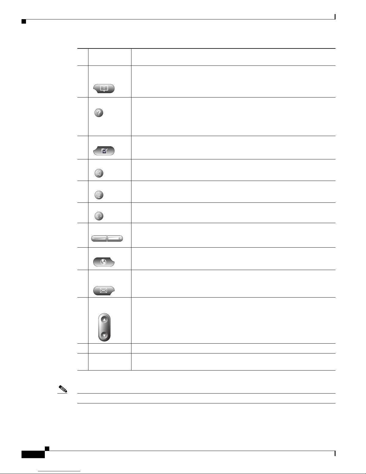
1 Handset with
indicator light
10111617 12131415
The light strip at the top of the handset blinks when the phone rings and can be
set to remain lit when there is a voice message.
8562
2 LCD screen Displays information about the Cisco IP phone, such as the time, date, phone
number, caller ID, line and call status, and the soft key tabs. The screen is
4.25 x 3 inches (10.79 x 7.62 cm) and has an adjustable contrast.
3 Cisco IP Phone
Indicates the Cisco IP phone model.
model type
4 Line or
speed-dial
button
Opens a new line or speed-dials the number on the LCD screen. Phones in the
Cisco IP Phone 7960 series have six line or speed-dial but tons, and phones in the
7940 series have two.
Cisco MGCP IP Phone Administrator Guide, Release 6.x and 7.x
1-3
Page 4
Cisco IP 7960G/7940G Phone Overview
Chapter 1 Product Overview
5 Footstand
Allows adjustment of the angle of the phone base.
adjustment
6 Directories
Provides access to call histories and directories.
button
7 i or ? button Provides online help for selected keys or features and network statistics about the
active call. Pressing the button and then the up or down scroll key displays a
descriptor of the key. For example, pressing the i or ? button, and then the up or
down scroll key displays a screen that instructs you how to scroll up and down
on the LCD.
8 Settings button Provides access to phone settings such as contrast and ring sound, network
configuration, and status information.
9 Speaker button Toggles the speaker on or off.
10 Mute button Toggles the mute on or off.
11 Headset button Toggles the headset on or off.
12 Volume button Increases or decreases the volume for the handset, headset, or speakerphone
(depending upon which is currently active). Also controls the ringer volume (if
the handset is in its cradle) and the LCD screen contrast.
13 Services button Provides access to any available phone services.
14 Messages
Provides access to a message system, if available.
button
15 Navigation
button
Allows scrolling through text and selection of features displayed on the LCD
screen.
16 Dial pad Works exactly like the dial pad on a traditional telephone.
17 Soft keys Activates any functions displayed on the corresponding LCD screen tabs. Soft
keys point to feature options displayed along the bottom of the LCD screen.
Note Refer to your call-agent (CA) or service-provider documentation for additional functionality.
Cisco MGCP IP Phone Administrator Guide, Release 6.x and 7.x
1-4
Page 5

Chapter 1 Product Overview
Figure 1-3 shows the connections on the back of the Cisco IP phone. Cisco IP 7960G/7940G phones have
the same hardware configuration.
Figure 1-3 Cisco IP Phone Cable Connection
Cisco IP 7960G/7940G Phone Overview
AUX
1 AC/DC adapter port (DC48V) for power connector. For redundancy, you can use the AC adapter
even if you are using inline power from Cisco Catalyst switches. The Cisco IP 7960G/7940G
phone can share the power being used from the inline power and external power source. If either
the inline power or the e xternal po wer goes do wn, the phone can switch entirely to the other po wer
source.
2 Power supply with AC plug.
3 Power cable with wall socket plug for connecting to power.
4 Network port (10 and 100 SW) RJ-45 to connect the phone to the network supporting 10- or
100-Mbps half- or full-duplex Ethernet connections to external devises. You can use either
Category 3 or Category 5 cabling for 10-Mpbs connections, but use Category 5 for 100-Mbps
connections. To avoid collisions, use full-duplex mode. You must use a straight-through cable on
this port. The phone can also obtain inline power from the Cisco Catalyst switch over this
connection.
Cisco MGCP IP Phone Administrator Guide, Release 6.x and 7.x
1-5
Page 6

Media Gateway Control Protocol Overview
5 Access port (10 and 100 PC) RJ-45 to connect a network device, such as a computer, to the phone
supporting from 10- to 100-Mbps half- or full-duplex Ethernet connections to external devices.
You can use either Category 3 or Category 5 cabling for 10-Mpbs connections, but use Category 5
for 100-Mbps connections. To avoid collisions, use full-duplex mode. You must use a
straight-through cable on this port.
6 Handset port for connecting a handset.
7 Headset port for connecting a headset. Enables the headset. The phone supports a f our- or si x-wire
headset jack. The volume and mute controls also adju st volume to the earpiece and mute the speech
path of the headset. The headset activ ation key is located on the fro nt of the Cisco IP 7960G/7940G
phone.
The phone supports the following Plantro nics four- or six-wire headsets: T ristar Mon aural, Encore
Monaural H91, and Encore Binaural H101.
When a headset is used, an amplifier is not required. However, a coil cord is required to connect
the headset to the headset port on the back of your Cisco IP 7960G/7940G phone. For informatio n
on ordering compatible headsets and coil cords for the Cisco IP 7960G/7940G phone, go to
http://cisco.getheadsets.com or http://vxicorp.com/cisco.
Chapter 1 Product Overview
Media Gateway Control Protocol Overview
Media Gateway Control Protocol (MGCP) is the Internet Engineering Task Force (IETF) standard for
multimedia conferencing ov er IP. MGCP is an ASCII-based, application-layer co ntrol pro tocol (def in ed
in RFC 2705) that can be used to establish, maintain, and terminate calls between two or more endpoints.
Like other VoIP protocols, MGCP is designed to address the functions of signaling and session
management within a packet telephony network. Signaling allows call information to be carried across
network boundaries. Session management provides the ability to control the attributes of an end-to-end
call.
One aspect of MGCP that differs from other VoIP protocols is that MGCP relies on a control server, or
call agent (CA), to control call progression, tones to apply, and call characteristics. MGCP endpoints
carry out instructions from the CA, which controls how calls proceed.
MGCP allows a control server to do the following:
• Determine the location of the target endpoint.
• Determine the media capabilities of the target endpoint. Usi ng Session Description Protocol (SDP) ,
MGCP determines the lowest level of common service between the endpoints. Conferences are
established using only the media capabilities that can be supported by all endpoints.
• Determine the availability of the target endpoint.
• Establish a session between the originating and tar get endpoint. If t he call can be completed, MGCP
establishes a session between the endpoints. MGCP also supports midcall changes, such as the
addition of another endpoint to the conference or the changing of a media characteristic or codec.
Note Conferences consist of two or more users and can be established by means of multicast or multiple
unicast sessions. A conference is an established session (or call) between two or more endpoints. In this
document, the terms conference and call are used interchangeably.
Cisco MGCP IP Phone Administrator Guide, Release 6.x and 7.x
1-6
Page 7

Chapter 1 Product Overview
MGCP is a client/server protocol. The CA handles all aspects of setting up calls to and from endpoints.
CAs or control servers provide the feature capabilities that a particular endpoint can use. Endpoints
connected to different CAs likely have a different set of features that they can use. Because all
call-control features are in the control server, each control server vendor decides which features are most
important, and therefore different control server vendors differ in essential features.
BTXML Support
The Cisco MGCP IP phone supports Basic Telephony eXtensible Markup Language. BTXML defines
XML elements for controlling the user interface of an IP telephone. It describes what information is
displayed on the screen and how to provide input using soft keys and hard keys.
For information about creating and using BTXML scripts on the phone, refer to the Cisco IP Phone
MGCP BTXML Version 2.0 Application Development Guide.
Cisco CallManager XML Support
BTXML Support
The Cisco MGCP IP phone supports Cisco CallManager XML cards that you configure to provide data
such as stock quotes, calendars, and directory lookups. Phone users access this information using phone
buttons such as the Services or Directories buttons or soft keys. See Chapter 4, “Managing Cisco MGCP
IP Phones,” for information about configuring these cards.
The phone supports Cisco CallManager XML up through version 3.0. It does not support the following
XML objects in version 3.1 and later: CiscoIPPhoneIconMenu, CiscoIPPhoneExecute,
CiscoIPPhoneError, and CiscoIPPhoneResponse.
For more information about using XML on your Cisco MGCP IP phone, refer to the following:
• IP Telephony
http://www.hotdispatch.com/cisco-ip-telephony
• Cisco Call Manager Services Developer Kit
http://www.cisco.com/pcgi-bin/dev_support/access_level/product_support
• Developing Cisco IP Phone Services by Darrick Deel, Mark Nelson, and Anne Smith,
ISBN 1-58705-060-9
Supported Network Features
The Cisco MGCP IP phone supports the following netw ork features. Depending on the features that y our
CA supports, some of these features may not be available on your phone.
• Interoperability with third-party CAs.
• Up to six MGCP connections and call appearances.
• Network startup using DHCP and TFTP.
• T elnet support—You can configure the phone to use Telnet to connect directly to the phone to debug
and troubleshoot. See Chapter 4, “Managing Cisco MGCP IP Phones,” for more information on
configuration parameters.
• Ping support—You can ping a specific Cisco IP phone to see if it is operational and how long the
response time is from the phone.
Cisco MGCP IP Phone Administrator Guide, Release 6.x and 7.x
1-7
Page 8

Supported Codecs and Dual Tone Multifrequency
• Traceroute support—You can use “traceroute” to see the path that a phone traverses in the route to
its desired destination.
• Remote reset support—You can configure a phone to enable a service provider to reset a phone from
a remote site. This feature provides a key tool for restarting the phone registration process with the
service provider call agent or proxy and for receiving a new or updated configuration or firmware
load from a designated TFTP server.
Supported Codecs and Dual Tone Multifrequency
The Cisco MGCP IP phone supports the following codecs:
• G.711 mu-law codec
• G.711 a-law codec
• G.729a codec
The phone also supports dual tone multifrequency (DTMF) out-of-band signaling for G.729a codecs
compliant to RFC 2833.
Chapter 1 Product Overview
Dialing and Messaging Features
The Cisco MGCP IP phone supports the following dialing and messaging features:
• Message-waiting indication—Lights to indicate that a ne w voice message is in a subscri ber mailbox.
If the user listens to the message but does not sa ve or delete it, the light remains on. If a user listens
to the message and saves or deletes it, the light goes off. The message-waiting indicator (MWI) is
controlled by the voice-mail server. The indication is saved over a phone upgrade or reboot.
• Notified entity—A CA can direct an endpoint to send notify messages to an alternate destination.
• Call waiting, call transfer, call forward (unconditional, busy, no answer), announcement, music on
hold, and volume control. These features must be supported by the CA.
• Three-way calling using an external mu ltipoint control u nit (MCU). This feature must be supported
by the C A .
Supported MGCP Commands
The Cisco MGCP IP phone supports the MGCP commands shown in Table 1-1.
Table 1-1 MGCP Commands
Command Description Direction
Notification Request Specifies events that generate notifications to the CA. CA to phone
Create Connection Creates an RTP connection. CA to phone
Modify Connection Modifies an existing RTP connection. CA to phone
Delete Connection Deletes an endpoint RTP connection. CA to phone
Audit Endpoint Queries endpoint status. CA to phone
Audit Connection Queries connection status. CA to phone
Cisco MGCP IP Phone Administrator Guide, Release 6.x and 7.x
1-8
Page 9

Chapter 1 Product Overview
Table 1-1 MGCP Commands (continued)
Command Description Direction
Restart in Progress Notifies the CA of the endpoint’s service state change. Phone to CA
Endpoint Configuration Specifies encoding for audio signals. CA to phone
Notification Indicates event occurrences. Phone to CA
Supported Languages and Character Set
The Cisco MGCP IP phone supports the ISO 8859-1 Latin1 characters and the following languages:
French (fr), Spanish (es), Catalan (ca), Basque (eu), Portuguese (pt), Italian (it), Albanian (sq),
Rhaeto-Romanic (rm), Dutch (nl), German (de), Danish (da), Swedish (sv), Norwegian (no), Finnish ( fi),
Faroese (fo), Icelandic (is), Irish (ga), Scottish (gd), English (en), Afrikaans (af), and Swahili (sw).
It does not support the following languages: Zulu (zu) and other Bantu languages using Latin
Extended-B letters; Arabic in North Africa; and Guarani (gn), which is missing the letters G, E, I, U, and
Y with tildes (~).
Supported Languages and Character Set
You can use ISO 8859-1 Latin1 characters in the following areas:
• Caller ID information—When an MGCP message is recei ved with ISO 8859-1 Latin1 characters in
the caller ID strings, those caller ID strings are displayed on the phone LCD with the correct
ISO 8859-1 Latin1 characters.
• Cisco CallManager XML—Services menu applications are written in Cisco CallManager XML
(CMXML). You can write language-specific applications for a particular region. For example, you
can write an application that displays the current weather in Sweden using Swedish language
characters. If you write the same application for a Spanish town, the characters you select could
translate the application into Spanish.
• Call-control displays (external MGCP XML card deck)—The XML deck used for MGCP call
control is downloaded to the phone, and those XML cards can be translated into the local language.
• Line-key labels—Line-key labels are set using an MGCP message that sets the label to the string
provided. Strings that contain ISO 8859-1 Latin1 characters are displayed properly.
• Soft-key labels—Soft-ke y l abels are set usi ng XML cards. XML cards, including call-control cards
and services applications, can provide soft keys with ISO 8859-1 Latin1 characters.
Note The i button text and the Settings menu are in English. These items are built into the phone image and
cannot be changed.
Cisco MGCP IP Phone Administrator Guide, Release 6.x and 7.x
1-9
Page 10

Supported Protocols
Supported Protocols
The Cisco MGCP IP phone supports the following protocols.
Table 1-2 Supported Protocols
Protocol Description
DHCP Dynamic Host Configuration Protocol. Client or manually configured using
DNS Domain Name System. Used in the Internet for translating names of network
Dynamic DNS and
TFTP
HTTP Hypertext Transfer Protocol. The phone contains limited support for
ICMP Internet Control Message Protocol. A network-layer Internet protocol that
IP Internet Protocol. A network layer protocol that sends datagram packets
RTP Real-Time Transport Protocol. Supports transport of real-time data (such as
SDP Session Description Protocol. An ASCII-based protocol that describes
SNTP Simple Network Time Protocol. Synchronizes computer clocks on an IP
Chapter 1 Product Overview
a local setup menu. DHCP is used to allocate and assign IP addresses. DHCP
allows you to move network devices from one subnet to another without
administrative attention. It allows connection of Cisco MGCP IP phones to
the network so that they become operational without having to manually
assign an IP address and additional network parameters.
The Cisco MGCP IP phone supports DHCP as defined in RFC 2131. By
default, the phone is DHCP-enabled.
nodes into addresses. MGCP uses DNS to resolve the host names of
endpoints into IP addresses.
You can configure additional DNS and TFTP servers. Upon bootup, the
phone first goes to the default TFTP server to download the configuration
files. If a new dynamic TFTP server is specified in the files, the phone
requests a new set of files from the specified server. If new DNS addresses
are specified in the files, the phone uses those addresses for lookups.
HTTP 1.1. The phone uses HTTP to retrieve Cisco CallManager XML files.
enables hosts to send error or control messages to other hosts. ICMP also
provides other information relevant to IP packet processing. The Cisco
MGCP IP phone supports ICMP as defined in RFC 792.
between nodes on the Internet. IP also provides features for ad dressing,
type-of-service (ToS) specification, fragmentation and reassembly, and
security. The Cisco MGCP IP phone supports IP as defined in RFC 791.
voice data) over data networks. RTP also has the ability to obtain
quality-of-service (QoS) information. The phone supports RTP as a media
channel.
multimedia sessions and their related scheduling information. Third-party
call control is supported using delayed media negoti ation, which is SDP data
that is not completely advertised in the initial call setup. SDP also supports
endpoints specified as fully qualified domain names (FQDNs). The Cisco
MGCP IP phone uses SDP for session description.
network. Current date and time are supported using SNTP including time
zone and daylight saving time. The Cisco MGCP IP phone uses SNTP for
date and time support.
Cisco MGCP IP Phone Administrator Guide, Release 6.x and 7.x
1-10
Page 11

Chapter 1 Product Overview
Table 1-2 Supported Protocols (continued)
Protocol Description
TCP Transmission Control Protocol. Provides a reliable byte-stream transfer
TFTP Trivial File Transfer Protocol. Allows files to be transferred from one
ToS Type of service. An indication of how an upper-layer protocol requires a
UDP User Datagram Protocol. Exchanges data packets without ackno wledgment s
VAD Voice activity detection. When enabled on a voice port or a dial peer, silence
Where to Go Next
service between endpoints on the Internet. The Cisco MGCP IP phone uses
TCP for Telnet and HTTP sessions.
computer to another over a network. The Cisco MGCP IP phone uses TFTP
to download configuration files and software updates.
lower-layer protocol to treat its messages. In SNA subarea routing, ToS
definitions are used by subarea nodes to determine the optimal route to
establish a given session. A ToS def inition comprises a virtual route number
and a transmission priority field. Also called class of service (CoS).
or guaranteed delivery. An MGCP network can use UDP as the underlying
transport protocol. If UDP is used, retransmissions are used to ensure
reliability.
is not transmitted over the network, only audible speech. Sound quality is
slightly degraded, but the connection monopolizes much less bandwidth.
Where to Go Next
• See Chapter 2, “Installing Cisco IP 7960G/7940G Phone Hardware on the Desktop or Wall,” for
placement of the phone on the desktop or wall and for cabling information.
• See Chapter 3, “Initializing Cisco MGCP IP Phones,” for installation of the firmware and
connecting the phone to power sources and the network.
• See Chapter 4, “Managing Cisco MGCP IP Phones,” for upgrading firmware and performing other
management tasks.
• See Chapter 5, “Monitoring Cisco MGCP IP Phones,” for information on debugging and on viewing
network statistics.
Cisco MGCP IP Phone Administrator Guide, Release 6.x and 7.x
1-11
Page 12

Where to Go Next
Chapter 1 Product Overview
Cisco MGCP IP Phone Administrator Guide, Release 6.x and 7.x
1-12
 Loading...