

Page 1

Cisco Interactive Experience Client 4600 Series
User Guide
Release 2.3.1
April 3, 2015
Americas Headquarters
Cisco Systems, Inc.
170 West Tasman Drive
San Jose, CA 95134-1706
USA
http://www.cisco.com
Tel: 408 526-4000
800 553-NETS (6387)
Fax: 408 527-0883
Text Part Number: OL-26457-08
Page 2

THE SPECIFICATIONS AND INFORMATION REGA RDING THE P RODUCTS IN TH IS MA NUAL ARE SUBJECT TO CHAN GE W ITHOUT NOT ICE. ALL
STATEMENTS, INFORMATION, AND RECOMMENDATIONS IN THIS MANUAL ARE BELIEVED TO BE ACCURATE BUT ARE PRESENTED WITHOUT
WARRANTY OF ANY KIND, EXPRESS OR IMPLIED. USERS MUST TAKE FULL RESPONSIBILIT Y FOR THEIR APPLICATION OF ANY PRODUCTS.
THE SOFTWARE LICENSE AND LIMITED WARRA NTY FO R THE A CCOMPA NYING PRODUCT A RE SET FORTH IN T HE INFORM ATION P ACKET THAT
SHIPPED WITH THE PRODUCT AND ARE INCORPORATED HEREIN BY THIS REFERENCE. IF YOU ARE UNABLE TO LOCATE THE SOFTWARE LICENSE
OR LIMITED WARRANTY, CONTACT YOUR CISCO REPRESENTATIVE FOR A COPY.
The following information is for FCC compliance of Class A devices: This equipment has been tested and found to comply with the limits for a Class A digital device, pursuant
to part 15 of the FCC rules. These limits are designed to provide reasonable protection against harmful interference when the equipment is operated in a commercial
environment. This equipment generates, uses, and can radiate radio-frequency energy and, if not installed and used in accordance with the instruction manual, may cause
harmful interference to radio communications. Operation of this equipment in a residential area is likely to cause harmful interference, in which case users will be required
to correct the interference at their own expense.
Modifications to this product not authorized by Cisco could void the FCC approval and negate your authority to operate the product.
The Cisco implementation of TCP header compression is an adaptation of a program developed by the University of California, Berkeley (UCB) as part of UCB’s public
domain version of the UNIX operating system. All rights reserved. Copyright © 1981, Regents of the University of California.
NOTWITHSTANDING ANY OTHER WARRANTY HEREIN, ALL DO CUMENT FILES AND SOFTWARE OF THESE SUPPL IERS ARE PROVI DED “AS IS” WITH
ALL FAULTS. CISCO AND THE ABOVE-NAMED SUPPLIERS DISCLAI M ALL WARRANTIE S, EXPRESSED OR
LIMITATION, THOSE OF MERCHANTABILITY, FITNESS FOR A PARTICUL AR PURPOSE AN D NONINFRINGE MENT OR ARISING FROM A COURSE OF
DEALING, USAGE, OR TRADE PRACTICE.
IN NO EVENT SHALL CISCO OR ITS SUPPLIERS BE LIABLE FOR ANY INDIRECT, SPECIAL, CONSEQUENTIAL, OR INCIDENTAL DAMAGES, INCLUDING,
WITHOUT LIMITATION, LOS T PROFITS OR LOSS OR DAMAGE TO DATA ARISIN G OUT OF THE USE OR INABILI TY TO USE THIS MA NUAL, EVEN I F CISCO
OR ITS SUPPLIERS HAVE BEEN ADVISED OF THE POSSIBILITY OF SU CH DAMA GES.
CCDE, CCENT, CCSI, Cisco Eos, Cisco HealthPresence, Cisco IronPort, the Cisco logo, Cisco Nurse Connect, Cisco Pulse, Cisco SensorBase, Cisco StackPower,
Cisco
StadiumVision, Cisco TelePresence, Cisco Unified Computing System, Cisco WebEx, DCE, Flip Channels, Flip for Goo d, Flip Mino, Flipshare (Design), Flip Ultra,
Flip Video, Flip Video (Design), Ins tant Broadban d, and Welcome to the Human Network are trademarks; Changing the Way We Work, Live, Play, and Learn, Cisco
Cisco
Capital (Design), Cisco:Financed (Stylized), Cisco Store, Flip Gift Card, and One Million Acts of Green are service marks; and Access Registrar, Aironet, AllTouch,
AsyncOS, Bringing the Meeting To You, Catalyst, CCDA, CCDP, CCIE, CCIP, CCNA, CCNP, CCSP, CCVP, Cisco, the Cisco
Cisco
IOS, Cisco Lumin, Cisco Nexus, Cisco Press, Cisco Systems, Cisco Systems Capital, the Cisco Systems logo, Cisco Unity, Collaboration Without Limitation,
Continuum, EtherFast, EtherSwitch, Event Center, Explorer, Follow Me Browsing, GainMaker, iLYNX, IOS, iPhone, IronPort, the IronPort logo, Laser Link, LightStream,
Linksys, MeetingPlace, MeetingPlace Chime Sound, MGX, Networkers, Networking Academy, PCNow, PIX, PowerKEY, PowerPanels, PowerTV, PowerTV (Design ),
PowerVu, Prisma, ProConnect, ROSA, SenderBase, SMARTnet , Spectrum Ex pert, StackWise , WebEx, and the WebEx logo are regi stered t rademarks of Cisco Systems, Inc.
and/or its affiliates in the United States and certain other countries.
All other trademarks mentioned in this document or website are the property of their respective owners. The use of th e word partn er does not imply a partn ershi p relations hip
between Cisco and any other company. (0910R)
Any Internet Protocol (IP) addresses and phone numbers us ed in this document are not intended to be actual addresses and phone numbers. Any examples, command disp lay
output, network topology diagrams, and other figures included in the document are shown for illustrative purposes only. Any use of actual IP addresses or phone numbers in
illustrative content is unintentional and coincidental.
Cisco Interactive Experience Client 4600 Series User Guide
© 2015 Cisco Systems, Inc. All rights reserved.
IMPLIED, INCLUDING, WITHOUT
Capital,
Certified Internetwork Expert logo,
Page 3

CONTENTS
CHAPTER
CHAPTER
CHAPTER
CHAPTER
CHAPTER
CHAPTER
CHAPTER
APPENDIX
APPENDIX
1 Introduction
2 Setting Up the IEC
3 Configuring Settings
4 Off-Line Caching
5 Upgrading the IEC
6 Debugging Console
7 Locally Configuring the IEC
A Compatible Peripherals
B Printers
APPENDIX
APPENDIX
APPENDIX
APPENDIX
APPENDIX
APPENDIX
APPENDIX
C Optical Scanners
D Magnetic Card Readers and Barcode Scanners
E Infrared Remote Controls
F Video Conferencing Using the Session Initiation Protocol Client
G Stream Live Video
H Content Guidelines
I HD Video Conferencing Between Two IECs Using the Video Encoder Card
Cisco Interactive Experience Client 4600 Series User Guide
iii
Page 4

Contents
iv
Cisco Interactive Experience Client 4600 Series User Guide
Page 5

Introduction
Revised: April 3, 2015
Chapter Overview
The Cisco Interactive Experience Client 4600 Series are state-less computer devices designed to power
various-purpose kiosks, Internet terminals, and specialized workstations. The Cisco Interactive
Experience Client 4600 Series can be managed remotely with the Cisco Interactive Experience Manager
console.
This user guide assumes that the Cisco Interactive Experience Manager has already been installed and
configured. If not, refer to the Cisco Interactive Experience Manager Installation Guide and the Cisco
Interactive Experience Manager Administrator Guide for instructions on how to install and configure
the software.
This chapter explains the audience and scope of this user guide and provides an overview of the Cisco
Interactive Experience Client 4600 Series.
The topics in this chapter are the following:
CHA P T E R
1
• What’s New in This Release, page 1-2
• About This User Guide, page 1-2
–
Terminology, page 1-2
–
Audience, page 1-3
–
Scope, page 1-3
• Cisco Interactive Services Solution, page 1-3
–
Cisco Interactive Experience Manager, page 1-4
–
Cisco Interactive Experience Client 4600 Series, page 1-5
–
Principles of Operation, page 1-5
• Kiosk Navigation, page 1-6
• Package Contents, page 1-7
• What You Will Need, page 1-7
Cisco Interactive Experience Client 4600 Series User Guide
1-1
Page 6

What’s New in This Release
What’s New in This Release
This release includes the following enhancements for the Cisco Interactive Experience Client (IEC) 4600
Series software:
• IEC SW has been upgraded to Ubuntu 14.04 and Qt 5.4. The existing Ubuntu distro is no longer
supported.
• Devices with long serial number are now supported in the IEM. The length of serial number accepted
is between 11 to 32 digits.
• IEM shows event logs in both Local and Device Time in the Events table.
• IEM now displays the number of registered and the number of online devices in each account.
• IEM now displays the number of items in Accounts, Users, Policies, Notifications, and Schedules.
• Added Severity and Facility columns in the Events table of the IEM.
• Custom font support for the IEC via @font-face.
• Websocket support for the IEC.
• Display wake up feature added so a user can set a device’s profile to make the connected display
turn on by any input from either a keyboard or mouse.
• Snapshot feature added to the SIP widget. The size of the snapshot taken is limited to 640x480
• The network utility ping has been added to the IEC's terminal shell commands to test the reachability
of a host from the IEC.
Chapter 1 Introduction
• Support for universal remote controllers. By uploading a LIRC config file for the remote to the new
IR Configuration property in the IEM, a user can use that remote instead of the default Cisco remote.
• Virtual keyboard support for the IEC's System Settings.
About This User Guide
This section describes what is included in this guide and explains who should use it.
Terminology
The following terms are used in this user guide.
• Accounts - Allow multiple organizations to configure and manage devices and policies in a single
Cisco Interactive Experience Manager instance. Use accounts to segregate users, devices, and
policies. Each organization will have at least one account.
• Administrators - People who have access to all accounts on the system. The Cisco Interactive
Experience Manager Installation Guide provides administrators with all the information necessary
to install and administer the Cisco Interactive Experience Manager.
• Device - The client at the kiosk such as the Cisco Interactive Experience Client 4600 Series or
Panasonic Connected Solutions Agent.
• Policies- An easy and flexible way of applying settings to multiple devices or users.
• Users - People who are associated with specific accounts on Cisco Interactive Experience Manager.
They cannot access any other account except for the ones that they are assigned to.
1-2
Cisco Interactive Experience Client 4600 Series User Guide
Page 7

Chapter 1 Introduction
Audience
Scope
Cisco Interactive Services Solution
The intended audience for this guide are administrators who will install, configure, troubleshoot, and maintain
the Cisco Interactive Experience Client 4600 Series hardware and software.
This user guide explains how to use the Cisco Interactive Experience Client 4600 Series.
This user guide provides instructions so that an administrator or user can:
• Connect the equipment
• Configure the system
• Configure the network
• Connect to the Cisco Interactive Experience Manager
• Register an account
• Configure local settings for demos
Cisco Interactive Services Solution
Cisco Interactive Services Solutions leverages the network as the platform to transform customer
experience with interactive digital media. Leveraging Cisco’s video, collaboration, and cloud
architectures, the solution allows large and small enterprises and public agencies to seamlessly provide
the most updated product or service information including educational content in real-time, improving
customer experience and increasing customer retention. With built-in remote management capabilities,
the solution enables organizations to get feedback instantaneously from end users to measure marketing
effectiveness and impact as well as dynamically provision and disperse relevant content. Effective reuse
of web content and applications along with remote delivery of content and advertisements helps increase
advertising revenues, improve business and customer processes, through effective management of digital
displays and open online spaces.
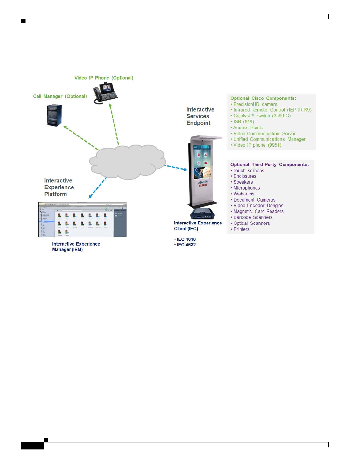
The Cisco Interactive Services Solution is the collective name for a product family that consists of
hardware and software including the Cisco Interactive Experience Manager software and the Cisco
Interactive Experience Client 4600 Series hardware and software.
Cisco Interactive Experience Client 4600 Series User Guide
1-3
Page 8
Cisco Interactive Services Solution
Figure 1-1 Cisco Interactive Services Solution Deployment Diagram
Chapter 1 Introduction
Cisco Interactive Experience Manager
The Cisco Interactive Experience Manager (IEM) is the management console that allows the
administrator to configure, control, and monitor Cisco Interactive Experience Client 4600 Series devices
as well as other devices such as the Panasonic Connected Solutions Agent. The devices are configured
remotely through a combination of device, user, profile, and policy settings from the Cisco IEM,
Configuration settings are distributed between user and device settings. Policies represent dynamic and
transportable setup rules.
With Cisco IEM, an administrator can perform the following functions:
• Configuration: A user can configure all device settings remotely including the startup URL, VPN,
display behavior, peripheral support.
• Policy Management: Policies provide an easy and flexible way for a user to apply settings to a group
of users or devices.
• Kiosk Control: A user can monitor and control the behavior of a kiosk remotely in real-time
including muting a station, locking out the user, sending messages to the user, etc.
• Session Management: A user can manage users’ sessions on the kiosks by setting time limits,
forcing the user to log out, etc.
Cisco Interactive Experience Client 4600 Series User Guide
1-4
Page 9

Chapter 1 Introduction
• Monitoring: Data is sent from the devices to the Cisco IEM at regular intervals. A user can analyze
the event logs and performance data to troubleshoot issues.
Cisco Interactive Experience Client 4600 Series
The Cisco Interactive Experience Client (IEC) 4600 Series is a robust, configurable, and manageable
web device designed for public venues and web-centric delivery. It is an integrated thin client device
with a complete operating system on board. The user interface is designed for ease-of-use and simplicity.
The interface also allows a large degree of customization based on the usage requirements.
The Cisco IEC 4600 Series can operate in either Stand-alone or Management mode. When operating in
Management mode, they adhere to the configuration profile set up by the administrator. This allows the
administrator to control and monitor the devices as needed. It is highly recommended that all the Cisco
IEC 4600 Series devices are managed and monitored using the Cisco Interactive Experience Manager as
it ensures consistent remote management with the option to configure the devices locally.
Additionally, the Cisco IEC 4600 Series can be configured to operate in either Desktop or Kiosk mode
to serve as web productivity workstations or public access terminals. Kiosk mode opens up a full-screen
web resource and restricts the user from opening multiple windows whereas Desktop mode allows
multiple windows to be opened with access to various web resources.
The Cisco IEC 4600 Series is powered by the COBRA browser operating system. This innovative
operating system is built to provide a “desktop-in-a-browser” environment, giving the users a familiar
feel of the desktop when interacting with Internet resources and applications. The COBRA browser is
compatible with all major Internet sites and gives the user a very intuitive and simple way of interacting
with web-based content and applications. Each Internet resource runs in its own window and is
represented by an automatically updating thumbnail ribbon on the bottom of the screen. In addition to
web browsing, the software supports Internet telephony client, Java, and PDF viewer.
The operating system of the Cisco IEC 4600 Series has the following capabilities:
Cisco Interactive Services Solution
• Full HTML browser
• Flexible windowing environment
• Single-window kiosk environment
• Dual screen support
• Touch screen support
• Display rotation
• Rich media playback support
• Remote management, control, and upgrade mechanism
Cisco IEC 4600 Series do not store user data locally. Rather, files created from an Internet resource are
typically stored at the Internet resource itself. It also allows for a USB media storage device or a camera
with a USB interface to be connected for file download and upload.
Principles of Operation
The following are principles of operation for this solution:
1. Devices need to exist on the IEM in order to be managed by it. Devices can either be provisioned
ahead of time or from the device interactively. If registered from the device interactively, the
installer has to use their account info to authorize the registration.
Cisco Interactive Experience Client 4600 Series User Guide
1-5
Page 10

Kiosk Navigation
Chapter 1 Introduction
2. Policy applied to the device overrides devices’ own configuration. Properties are additive,
therefore if policy doesn’t override a property, the property will stay unchanged.
3. Multiple policies can be attached to the same device (group). If policies contain conflicting
settings, the policy that is higher in the stack order takes precedence. Device policies take
precedence over group policies.
4. IEC and IEM software versions are best-effort compatible. A device that has a version that is not
actively supported by the IEM will still be supported although some things may not have full
functionality. A device version which is out of sync is indicated by the red FW flag. Communication
between client and the IEM is defined by the communication protocol and specification that defines
capabilities of each FW build: older communication protocols are supported in the newer IEM
builds, but older specifications that reflect properties of the firmware are often not fully compatible
with the later versions.
5. Policies can be persistent or transient (applied for short periods of time). Persistent policies are
long-term or permanent. Persistent policies are applied when the device is booted or rebooted.
Persistent policies are permanent until they are unapplied.
Transient, runtime, or IsAction policies are created by checking the IsAction checkbox when
creating the policy or in the General tab of the policy. Transient policies are marked by a blue circle
with a white arrow and are made available in form of a button under “Custom Actions”. These
policies change the settings on the devices temporarily and will be reset by changing the settings
within the policy, by applying another IsAction policy with settings that will reverse the original
settings, or on the next reboot. IsAction policies can only work for runtime properties, which are
marked by an orange arrow in the policy or profile.
6. Notifications and alerts work on a subscription basis. Once notification/alert has been created, it
has to be assigned to a user. Notification/alert can submit to a third party application collecting the
data – the URL has to be provisioned through User profile.
7. In order to optimize screen behavior, the application has to implement native components.
Native components are available in form of a Browser API (refer to the documentation) and
essentially move resource-intensive or asynchronously used components outside of the browser
process-space.
Kiosk Navigation
If the navigation panel is enabled, customers will interact with the buttons on the navigational panel. If
the display is a touch screen, customers can touch the buttons and virtual keyboard with their fingers.
Otherwise, the customers can use a mouse to choose the buttons and a keyboard to enter keystrokes. The
following buttons are visible to the customer on the navigational panel:
• Question/Help button – Customer uses this button to access a help page.
• Go back one page button – Customer uses this arrow to go to a previous page.
• Stop loading this page button – Customer uses this button to stop the current page from loading.
• Go to startup URL button – Customer uses this button to go to the startup URL
• Reload current page button – Customer uses this button to reload the current page.
• Go forward one page button – Customer uses this arrow to go to the next page.
• Print currently loaded page button – Customer uses this button to print the current page if the kiosk
is hooked up to a printer.
1-6
Cisco Interactive Experience Client 4600 Series User Guide
Page 11

Chapter 1 Introduction
Figure 1-2 Navigational Panel on Kiosk
Package Contents
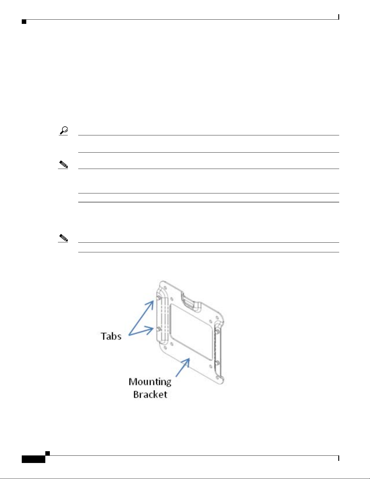
The package should contain the following components:
• Cisco IEC 4600 Series
• Power adapter
• Mounting plate
• Four mounting screws
Figure 1-3 Cisco IEC 4600 Series and Mounting Bracket
Package Contents
If any of the contents are missing, contact http://cisco.com/en/US/support.
What You Will Need
Note To optimize the video quality, the IEC 4600 Series should be connected to a 1080p LED or LCD video
display using either HDMI (preferred) or VGA.
To install and configure the Cisco IEC 4600 Series, you will need the following:
• Video monitor (non-touch screen or touch screen)
• HDMI or VGA cable
• USB cable if using a touch screen
• USB keyboard (wired or wireless)
Cisco Interactive Experience Client 4600 Series User Guide
1-7
Page 12

What You Will Need
Chapter 1 Introduction
• USB mouse (wired or wireless)
• Webcam (optional)
• Ethernet cable
• Wireless network credentials (optional)
• IEM installed and configured
After you have assembled all the equipment, proceed to Chapter 2.
1-8
Cisco Interactive Experience Client 4600 Series User Guide
Page 13

Setting Up the IEC
Revised: April 3, 2015
Chapter Overview
This chapter explains how to do set up the equipment and configure the Cisco IEC 4600 Series so that it
displays the startup URL.
Topics in this chapter include:
• Connecting the Hardware, page 2-2
–
IEC Dimensions, page 2-2
–
IEC Specifications, page 2-2
–
Environmental Tolerance Ranges, page 2-4
–
Warnings, page 2-5
CHA P T E R
2
–
Product Disposal, page 2-10
–
RF Exposure, page 2-12
–
Choosing a Location, page 2-14
–
Mounting the Hardware, page 2-14
–
Connecting and Powering Up, page 2-15
• Registering the IEC, page 2-16
• Configuring the System, page 2-17
• Connecting to the Network, page 2-21
–
Configuring an Ethernet (Wired) Connection, page 2-21
–
Configuring a Wireless Connection, page 2-25
• Connecting to the Cisco IEM, page 2-33
–
Applying a Policy, page 2-33
• Calibrating the Touchscreen, page 2-38
• Using Emergency Configuration Mode, page 2-39
• Using a VNC Viewer, page 2-42
Cisco Interactive Experience Client 4600 Series User Guide
2-1
Page 14

Connecting the Hardware
Connecting the Hardware
The Cisco IEC 4600 Series is easy to setup. This section describes how to choose a location for the
device, mount it, and connect it to a video display, keyboard, mouse, and electrical outlet.
IEC Dimensions
The table below contains the dimensions of the IEC 4600 Series.
Ta b l e 2-1 Cisco IEC 4600 Series Dimensions
US Customary Unit Modern Metric Unit
Width Depth Height Width Depth Height
7.3 inches 7.4 inches 1.9 inches 18.5 cm 18.8 cm 4.8 cm
IEC Specifications
Chapter 2 Setting Up the IEC
The table below contains the IEC specifications for models IEC 4610 and IEC 4632.
Ta b l e 2-2 Cisco IEC 4600 Series Specifications
Features IEC 4610 IEC 4632
PCBA Form Factor
Board size 6.0 in. x 6.0 in. (150 mm x 150 mm)
Processor
CPU Intel Celeron M Processor
Memory
Type DDR3-800/1066 memory
DIMM Slot)
(SO-
System memory size 2 GB
Storage
Type SATA socket Disk on Module (DOM) SATA socket Disk on Module (DOM)
Storage Memory Size 8 GB
BIOS Flash Memory
Memory Size 32 Mbit
Ethernet
Count 1 1
Speeds 10/100/1000 Mbps 10/100/1000 Mbps
Connectors 1 Port RJ45 with transformer 1 Port RJ45 with transformer
6.0 in. x 6.0 in. (150 mm x 150 mm)
Intel Core 2 Duo Processor
DDR3-800/1066 memory
(SO-DIMM Slot)
4 GB
32 GB
32 Mbit
2-2
Cisco Interactive Experience Client 4600 Series User Guide
Page 15

Chapter 2 Setting Up the IEC
Features IEC 4610 IEC 4632
Video
Onboard GS45 HDMI GS45 HDMI
Connectors 1 HDMI port
USB
Type USB 2.0 controller USB 2.0 controller
Connectors 2 Right USB A type
1 VGA port
2 Back USB A type
Connecting the Hardware
1 HDMI port
1 VGA port
2 Right USB A type
2 Back USB A type
1 Front USB A type
1 Front USB A type
WiFi+Bluetooth
Count 1 1
Speed 802.11 b/g, Bluetooth V2.1+EDR 802.11 b/g, Bluetooth V2.1+EDR
Front I/O
LED 1 Green LED
1 Red LED
1 Green LED
1 Red LED
IR receiver 1 Built-in IR receiver 1 Built-in IR receiver
USB 1 USB connector (for preinstall
USB connector (for preinstall device)
device)
Back I/O
DC jack 1 12V DC in connector 1 12V DC in connector
Video 1 VGA port
1 HDMI port
1 VGA port
1 HDMI port
Ethernet 1 RJ45 connector with dual LEDs 1 RJ45 connector with dual LEDs
USB 1 USB two-stack connector 1 USB two-stack connector
Left I/O
COM 1 x 3.5 mm phone jack type 1 x 3.5 mm phone jack type
IR extension 1 1-IR extension cable 1 1-IR extension cable
Audio 1 Audio port (MIC-in)
1 Audio port (line-out)
1 Audio port (MIC-in)
1 Audio port (line-out)
USB 1 USB two-stack connector 1 USB two-stack connector
Right I/O
Buttons 1 Power On/Off button (with
soft/hard power option)
1 Reset button
1 Power On/Off button (with
soft/hard power option)
1 Reset button
Cisco Interactive Experience Client 4600 Series User Guide
2-3
Page 16

Connecting the Hardware
Features IEC 4610 IEC 4632
Power
Adapter 12V@4A (48W)
Input 100V - 240V ~1A 50-60HZ
Output 12V ~4A
12V@4A (48W)
Input 100V - 240V ~1A 50-60HZ
Output 12V ~4A
Power consumption 12V@48W maximum 12V@48W maximum
CPU VR Intel Mobile Voltage Positioning
(Intel MVP6)
Structure
Intel Mobile Voltage Positioning
(Intel MVP6) Structure
Environmental Tolerance Ranges
Refer to the table below for the environmental tolerance ranges.
Ta b l e 2-3, Part 1 Cisco IEC 4600 Series Environmental Tolerance Ranges: Temperature
Temperature
Operating
ng-term or
lo
short-term
Non-operating or
stora
ge
1. Ambient.
1
US Customary Unit Modern Metric Unit
Minimum Maximum Minimum Maximum
32°F 104°F 0°C 40°C
-4°F 158°F -20°C 70°C
Chapter 2 Setting Up the IEC
Ta b l e 2-3, Part 2 Cisco IEC 4600 Series Environmental Tolerance Ranges: Humidity
Relative Humidity
1
Minimum Maximum
Operating 10 percent (Indoor) 85 percent (Indoor)
Non-operating or storage 0 percent (Indoor and Outdoor) 95 percent (Indoor and Outdoor)
1. Noncondensing; ambient.
Ta b l e 2-3, Part 3 Cisco IEC 4600 Series Environmental Tolerance Ranges: Altitude
Altitude
1
US Customary Unit Modern Metric Unit
Minimum Maximum Minimum Maximum
Operating and
n-operating
no
1. Above sea level.
0 feet 6,561 feet 0 meters 2,000 meters
2-4
Cisco Interactive Experience Client 4600 Series User Guide
Page 17

Chapter 2 Setting Up the IEC
Warnings
Installation Instructions
Connecting the Hardware
Warning
Waarschuwing
Varoitus
Attention
Warnung
Avvertenza
Advarsel
Aviso
¡Advertencia!
Read the installation instructions before connecting the system to the power source.
Raadpleeg de installatie-instructies voordat u het systeem op de voedingsbron aansluit.
Lue asennusohjeet ennen järjestelmän yhdistämistä virtalähteeseen.
Avant de brancher le système sur la source d'alimentation, consulter les directives d'installation.
Vor dem Anschließen des Systems an die Stromquelle die Installationsanweisungen lesen.
Consultare le istruzioni di installazione prima di collegare il sistema all'alimentatore.
Les installasjonsinstruksjonene før systemet kobles til strømkilden.
Leia as instruções de instalação antes de ligar o sistema à fonte de energia.
Lea las instrucciones de instalación antes de conectar el sistema a la red de alimentación.
Cisco Interactive Experience Client 4600 Series User Guide
2-5
Page 18

Connecting the Hardware
Chapter 2 Setting Up the IEC
Varning!
Figyelem
Läs installationsanvisningarna innan du kopplar systemet till strömförsörjningsenheten.
Mielott áramforráshoz csatlakoztatná a rendszert, olvassa el az üzembe helyezési útmutatót!
2-6
Cisco Interactive Experience Client 4600 Series User Guide
Page 19

Chapter 2 Setting Up the IEC
Battery Handling
Connecting the Hardware
Warning
Waarschuwing
Varoitus
Attention
Warnung
Avvertenza
Advarsel
There is the danger of explosion if the battery is replaced incorrectly. Replace the battery only with
the same or equivalent type recommended by the manufacturer. Dispose of used batteries according
to the manufacturer’s instructions.
Er is ontploffingsgevaar als de batterij verkeerd vervangen wordt. Vervang de batterij slechts met
hetzelfde of een equivalent type dat door de fabrikant aanbevolen is. Gebruikte batterijen dienen
overeenkomstig fabrieksvoorschriften weggeworpen te worden.
Räjähdyksen vaara, jos akku on vaihdettu väärään akkuun. Käytä vaihtamiseen ainoastaan samantai vastaavantyyppistä akkua, joka on valmistajan suosittelema. Hävitä käytetyt akut valmistajan
ohjeiden mukaan.
Danger d'explosion si la pile n'est pas remplacée correctement. Ne la remplacer que par une pile
de type semblable ou équivalent, recommandée par le fabricant. Jeter les piles usagées
conformément aux instructions du fabricant.
Bei Einsetzen einer falschen Batterie besteht Explosionsgefahr. Ersetzen Sie die Batterie nur durch
den gleichen oder vom Hersteller empfohlenen Batterietyp. Entsorgen Sie die benutzten Batterien
nach den Anweisungen des Herstellers.
Pericolo di esplosione se la batteria non è installata correttamente. Sostituire solo con una di tipo
uguale o equivalente, consigliata dal produttore. Eliminare le batterie usate secondo le istruzioni
del produttore.
Det kan være fare for eksplosjon hvis batteriet skiftes på feil måte. Skift kun med samme eller
tilsvarende type som er anbefalt av produsenten. Kasser brukte batterier i henhold til produsentens
instruksjoner.
Aviso
Existe perigo de explosão se a bateria for substituída incorrectamente. Substitua a bateria por uma
bateria igual ou de um tipo equivalente recomendado pelo fabricante. Destrua as baterias usadas
conforme as instruções do fabricante.
¡Advertencia!
Existe peligro de explosión si la batería se reemplaza de manera incorrecta. Reemplazar la batería
exclusivamente con el mismo tipo o el equivalente recomendado por el fabricante. Desechar las
baterías gastadas según las instrucciones del fabricante.
Cisco Interactive Experience Client 4600 Series User Guide
2-7
Page 20

Connecting the Hardware
Chapter 2 Setting Up the IEC
Varning!
Figyelem
Explosionsfara vid felaktigt batteribyte. Ersätt endast batteriet med samma batterityp som
rekommenderas av tillverkaren eller motsvarande. Följ tillverkarens anvisningar vid kassering av
använda batterier.
Existe risco de explosão se a bateria for substituída incorretamente. Substitua a bateria somente
com o mesmo tipo ou um tipo equivalente recomendado pelo fabricante. Descarte as baterias usadas
de acordo com as instruções do fabricante.
2-8
Cisco Interactive Experience Client 4600 Series User Guide
Page 21

Chapter 2 Setting Up the IEC
Connecting the Hardware
Advarsel
Der er risiko for eksplosion, hvis batteriet ikke udskiftes korrekt. Batteriet må kun udskiftes med
samme eller med en tilsvarende type, som anbefales af producenten. Bortskaf brugte batterier i
overensstemmelse med producentens instruktioner.
Cisco Interactive Experience Client 4600 Series User Guide
2-9
Page 22

Connecting the Hardware
Product Disposal
Chapter 2 Setting Up the IEC
Warning
Waarschuwing
Varoitus
Attention
Warnung
Avvertenza
Advarsel
Aviso
¡Advertencia!
Varning!
Ultimate disposal of this product should be handled according to all national laws and regulations.
Het uiteindelijke wegruimen van dit product dient te geschieden in overeenstemming met alle
nationale wetten en reglementen.
Tämä tuote on hävitettävä kansallisten lakien ja määräysten mukaisesti.
La mise au rebut ou le recyclage de ce produit sont généralement soumis à des lois et/ou directives
de respect de l'environnement. Renseignez-vous auprès de l'organisme compétent.
Die Entsorgung dieses Produkts sollte gemäß allen Bestimmungen und Gesetzen des Landes
erfolgen.
Lo smaltimento di questo prodotto deve essere eseguito secondo le leggi e regolazioni locali.
Endelig kassering av dette produktet skal være i henhold til alle relevante nasjonale lover og
bestemmelser.
Deitar fora este produto em conformidade com todas as leis e regulamentos nacionais.
Al deshacerse por completo de este producto debe seguir todas las leyes y reglamentos nacionales.
Vid deponering hanteras produkten enligt gällande lagar och bestämmelser.
2-10
Aviso
O descarte definitivo deste produto deve estar de acordo com todas as leis e regulamentações
nacionais.
Advarsel
Cisco Interactive Experience Client 4600 Series User Guide
Endelig bortskaffelse af dette produkt skal ske i henhold til gældende love og regler.
Page 23

Chapter 2 Setting Up the IEC
Connecting the Hardware
Varning!
Figyelem
Opemena
Vid deponering hanteras produkten enligt gällande lagar och bestämmelser.
FCC Compliance Information Statement (for USA only)
Product IEP-46XX-HW-K9
This equipment has been tested and found to comply with the limits for a Class B digital device, pursuant
o Part 15 of the FCC Rules. These limits are designed to provide reasonable protection against harmful
t
interference in a residential installation. This equipment generates, uses and can radiate radio frequency
energy and, if not installed and used in accordance with the instructions, may cause harmful interference
to radio communications. However, there is no guarantee that interference will not occur in a particular
installation. If this equipment does cause harmful interference to radio or television reception, which can
be determined by turning the equipment off and on, the user is encouraged to try to correct the
interference by one or more of the following measures:
• Reorient or relocate the receiving antenna.
• Increase the separation between the equipment and receiver.
• Connect the equipment into an outlet on a circuit different from that to which the receiver is
connected.
Consult the dealer or an experience
d radio/TV technician for help.
Cisco Interactive Experience Client 4600 Series User Guide
2-11
Page 24

Connecting the Hardware
Note Equipment must be installed and operated using the relevant manuals and only installed with the correct
cables and connectors. Cisco Systems Inc. is not responsible for any radio or television interference
caused by unauthorized changes or modifications to this equipment. Unauthorized changes or
modifications could void the user’s authority to operate the equipment.
This device complies with Part15 of the FCC rules. Operation is subject to the following two conditions:
(1) this device may not cause harmful interference, and (2) this device must accept any interference
received, including interference that may cause undesired operation.
Responsible party:
Cisco Systems Inc.
170 West Tasman Drive
San Jose, CA 95134
USA
+408 526-7208
Chapter 2 Setting Up the IEC
RF Exposure
Caution To ensure compliance with various national and international Electromagnetic Field (EMF) standards,
The Cisco products are designed to comply with the following national and international standards on
Human Exposure to Radio Frequencies.
• US 47 Code of Federal Regulations Part 2 Subpart J
• American National Standards Institute (ANSI) / Institute of Electrical and Electronic Engineers /
IEEE C 95.1 (99)
• International Commission on Non Ionizing Radiation Protection (ICNIRP) 98
• Ministry of Health (Canada) Safety Code 6. Limits on Human Exposure to Radio Frequency Fields
in the range from 3kHz to 300 GHz
• Australia Radiation Protection Standard
the system should only be operated with Cisco approved antennas and accessories.
THIS DEVICE MEETS THE FCC GUIDELINES FOR EXPOSURE TO RADIO WAVES
Your device includes a radio transmitter and receiver. It is designed not to exceed the limits for exposure
to radio waves (radio frequency electromagnetic fields) as referenced in FCC Part 1.1310. The guidelines
are based on IEEE ANSI C 95.1 (92) and include a substantial safety margin designed to assure the safety
of all persons, regardless of age and health.
As such the systems are designed to be operated as to avoid contact with the antennas by the end user.
It is recommended to set the system in a location where the antennas can remain at least a minimum
distance as specified from the user in accordance to the regulatory guidelines which are designed to
reduce the overall exposure of the user or operator.
The device has been tested and found compliant with the applicable regulations as part of the radio
certification process.
2-12
Cisco Interactive Experience Client 4600 Series User Guide
Page 25

Chapter 2 Setting Up the IEC
Connecting the Hardware
Ta b l e 2-4
Separation Distance
MPE Distance Limit
x.xxx
mW^cm 2
x cm / x inches x.xx
mW/cm^2
The US Food and Drug Administration has stated that present scientific information does not indicate
the need for any special precautions for the use of wireless devices. The FCC recommends that if you
are interested in further reducing your exposure then you can easily do so by reorienting antennas away
from the user or placing the antennas at a greater separation distance then recommended or lowering the
transmitter power output.
THIS DEVICE MEETS THE HEALTH CODE 6 GUIDELINES FOR EXPOSURE TO RADIO WAVES
The device has been evaluated and found compliant with the requirements set forth in Industry Canada
RSS-10
2, Evaluation Procedure for Mobile and Portable Radio Transmitters with respect to health
Canada Safety Code 6 for Exposure of Humans to Radio Frequency Fields.
Health Canada states that present scientific informat
ion does not indicate the need for any special
precautions for the use of wireless devices.
THIS DEVICE MEETS INTERNATIONALGUIDELINES FOR EXPOSURE TO RADIO WAVES
Your device includes a radio transmitter and receiver. It is designed not to exceed the limits for exposure
o radio waves (radio frequency electromagnetic fields) recommended by international guidelines. The
t
guidelines were developed by an independent scientific organization (ICNIRP) and include a substantial
safety margin designed to assure the safety of all persons, regardless of age and health.
As such the systems are designed to be operated as to a
void contact with the antennas by the end user.
It is recommended to set the system in a location where the antennas can remain at least a minimum
distance as specified from the user in accordance to the regulatory guidelines which are designed to
reduce the overall exposure of the user or operator.
Ta b l e 2-5
Separation Distance
MPE Distance Limit
x.xxx
mW^cm 2
x cm / x inches x.xx
mW/cm^2
The World Health Organization has stated that present scientific information does not indicate the need
for any special precautions for the use of wireless devices.
However if you are interested in further reducing your exposure then you can easily do so by reorienting
nnas away from the user or placing the antennas at a greater separation distance then recommended.
ante
Additional information on the subject can be found at the following links
• FCC Web site: http://www.fcc.gov/encyclopedia/radio-frequency-safety
• FDA Website http://www.fda.gov
• Health Canada: http://hc-sc.gc.ca/ewh-semt/radiation/index-eng.php
• World Health Organization Internal Commission on Non-Ionizing Radiation Protection at
www.who.int/emf
• Mobile Manufacturers Forum at www.mmfai.org
Cisco Interactive Experience Client 4600 Series User Guide
2-13
Page 26
Connecting the Hardware
Choosing a Location
The Cisco IEC 4600 Series is intended for indoor use only. The Cisco IEC 4600 Series must be located
within eight feet of an electrical outlet for the power adapter to reach the outlet.
Mounting the Hardware
The Cisco IEC 4600 Series comes with an optional mounting bracket, which makes mounting the unit
to a monitor with a VESA mount or various other surfaces (walls, desks, etc.) easy.
Tip Since Cisco IEC 4600 Series is designed for convectional cooling, vertical mounting is highly
recommended.
Note If you want to use a remote control and you will not use an IR extender as is recommended, the infrared
(IR) must be in sight of the user. Hence you will need to determine an alternative mounting to that which
is recommended here.
Chapter 2 Setting Up the IEC
Step 1 Locate a vertical surface near the video display where you want the IEC 4600 Series to be mounted.
Step 2 Attach the mounting place to the video display, wall, or kiosk. Mount so that the up arrow points upwards
and is visible.
Note If mounting to sheet rock or other porous surface, use appropriate mounting hardware (not supplied).
Figure 2-1 Ports on the Cisco IEC 4600 Series
2-14
Cisco Interactive Experience Client 4600 Series User Guide
Page 27

Chapter 2 Setting Up the IEC
Step 3 Carefully slide the IEC 4600 Series onto the tabs on the mounting hardware. The display and network
connections will be facing to the floor.
Connecting and Powering Up
The back of the Cisco IEC 4600 Series contains multiple ports that will be used to connect to the video
display, keyboard, mouse, network, and electrical outlet. Follow the steps below to connect the
equipment and power on the device.
Step 1 Connect an USB keyboard to one of the USB ports on the Cisco IEC 4600 Series.
Tip It is recommended that you use a wired keyboard as opposed to a wireless keyboard. With some wireless
keyboards, the IEC detects it as a second touchscreen instead of a keyboard.
Figure 2-2 Ports on the Cisco IEC 4600 Series
Connecting the Hardware
Step 2 Connect an USB cable or wireless USB adapter for a mouse to an USB port on the Cisco IEC 4600
Series.
Step 3 (Optional) Connect an USB cable for a webcam to an USB port on the Cisco IEC 4600 Series.
Step 4 (Optional) Connect other peripherals such as speakers, microphone, magnetic card reader, barcode
scanner, printer, etc.
Note If using the RS232 port for a RCA, TRS, or TRRS connector, the tip of the connector
corresponds to pin 2 and the ring of the connector corresponds to pin 3 on a DB-9 connector.
Step 5 Connect the video display cable to either the VGA or the HDMI port on the Cisco IEC 4600 Series. Then
connect the other end of the cable to the video display.
Tip To optimize the video quality, the IEC 4600 Series should be connected to a 1080p LED or LCD
video display using the HDMI cable.
Step 6 If the display is a touch screen, connect an USB cable to it and an USB interface on the Cisco IEC 4600
Series.
Step 7 Plug the power cord for the video display into an electrical outlet.
Cisco Interactive Experience Client 4600 Series User Guide
2-15
Page 28
Registering the IEC
Step 8 Turn on the power to the video display.
Step 9 Connect an Ethernet cable to the LAN port on the Cisco IEC 4600 Series. Connect the other end of the
Step 10 Connect the power adapter to the DC 12V in connector on the Cisco IEC 4600 Series.
Step 11 Plug the power adapter into an electrical outlet.
Chapter 2 Setting Up the IEC
Ethernet cable to an Ethernet wall jack or Ethernet port on a router or switch.
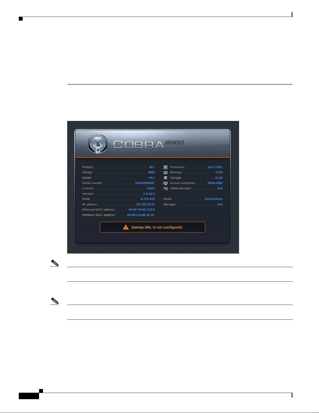
The Cisco IEC 4600 Series will initialize now. When it finishes initializing, the COBRA screen appears.
Figure 2-3 Initialization Screen
Note After initialization “Startup URL is not configured” will appear at the top of the screen. It is referring to
the URL that the Cisco IEC 4600 Series will use to display content once it is configured.
Record the serial number and IP address shown on the COBRA screen.
Note If there are any problems with the initial configuration or the network, the system will not initialize and
the Cobra screen will not appear. If that happens, refer to “Using Emergency Configuration Mode”.
Registering the IEC
The IEC 4600 Series must first be registered in the IEM to manage it remotely. To register a device, you
will need the following:
• Enough licenses in the IEM to cover the new device
Cisco Interactive Experience Client 4600 Series User Guide
2-16
Page 29
Chapter 2 Setting Up the IEC
• The IEC’s serial number, which can be found on the bottom of the device
• User credentials on the IEM
Configuring the System
A license for the device must exist in the IEM before the
exist in the IEM to cover the device, the device will not register and it cannot be managed by the IEM
until a license is obtained for it. For more information about licensing, refer to the Cisco Interactive
Experience Manager Administrator Guide.
You will register the IEC using the New Device button within the Devices’ Edit menu. Refer to the
Adding a New Device” section of the Cisco Interactive Experience Manager Administrator Guide for
“
instructions on how to add the device.
Configuring the System
To configure the system, you will need the Cisco IEM URL. If you do not know the URL, contact the
administrator in your company who installed and configured the Cisco IEM.
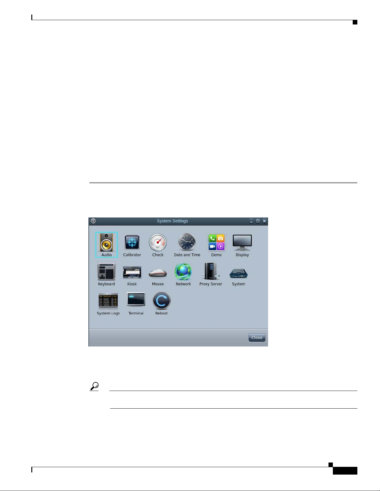
Step 1 Press Ctrl-Alt-S. The combination of these three keys opens the System Settings window.
Figure 2-4 System Settings Window
device can be registered. If a license does not
In Chapter 7, you will learn how to configure each of the settings. For now you will learn how to
configure the system settings to get started.
Step 2 Click the System icon.
Tip You can use either the mouse or arrow keys on a keyboard to navigate the icons within the
System Settings window.
Step 3 Now you will configure the system to connect the Cisco IEC 4600 Series to the Cisco IEM. By default,
the Server tab is displayed. If the Server tab is not displayed, click the Server tab.
Cisco Interactive Experience Client 4600 Series User Guide
2-17
Page 30

Configuring the System
Chapter 2 Setting Up the IEC
Figure 2-5 Server Tab
2-18
Step 4 Enter the device name in the Device name field. The name you choose will be used in the Cisco IEM to
identify this device.
Note Only alphanumeric and underscores can be entered in the device name field.
Step 5 Enter the device description in the Device Description field.
Step 6 Enter the device location in the Device Location field.
Step 7 Enter the Cisco IEM address in the IEM URL field or check the Get IEM server address from DHCP
check box.
Step 8 Click the Managed by Cisco IE Manager (IEM) radio button. The Account Details dialog box opens.
The information entered here will be used to access the Cisco IEM. If you do not know this information,
obtain it from the administrator who installed and configured the Cisco IEM.
Step 9 Enter the account name in the Account field.
Cisco Interactive Experience Client 4600 Series User Guide
Page 31

Chapter 2 Setting Up the IEC
Figure 2-6 Account Details Dialog Box
Configuring the System
Step 10 Enter the user name in the User name field.
Step 11 Enter the password in the Password field. To verify that you entered the correct password, check the
Show password check box to view the password entered.
Step 12 Click Register.
Step 13 Once the account is registered, you will see the word “Success”.
Figure 2-7 Registration Successful Notification
Step 14 Click Reboot now.
Step 15 When you complete the selections in this window, click Apply.
Step 16 To exit the System window, click Close.
Cisco Interactive Experience Client 4600 Series User Guide
2-19
Page 32

Configuring the System
Step 17 In the System Settings window, click Reboot.
Chapter 2 Setting Up the IEC
Figure 2-8 Reboot Icon in the System Settings Window
The COBRA screen appears.
Figure 2-9 COBRA Screen
2-20
Next you will connect the Cisco IEC 4600 Series to the Cisco IEM.
Cisco Interactive Experience Client 4600 Series User Guide
Page 33

Chapter 2 Setting Up the IEC
Connecting to the Network
The Cisco IEC 4600 Series can be connected to the network using an Ethernet (wired) or wireless
connection. Either can be configured using DHCP or entering an IP address.
By default, the IEC 4600 Series is configured to look for a DHCP-enabled Ethernet network. If you are
necting to another type of network (either static IP, Wireless, or both), you need to configure the
con
network using the Emergency Configuration Mode as described in “Using Emergency Configuration
Mode”. Once in Emergency Configuration Mode, click the Network icon and then proceed to either
“Configuring an Ethernet Connection” or “Configuring a Wireless Connection”.
Configuring an Ethernet (Wired) Connection
If you want to configure an Ethernet (wired) connection to the network using DHCP or a static IP
address, follow these steps:
Step 1 Press Ctrl-Alt-S to display the System Settings window.
Step 2 Click the Network icon.
Connecting to the Network
Figure 2-10 Network Icon in System Settings Window
Step 3 If Ethernet is not the current interface, click the Ethernet radio button.
Step 4 Choose to use DHCP or a static IP address:
To use DHCP, check the Use
DHCP check box.
Cisco Interactive Experience Client 4600 Series User Guide
2-21
Page 34

Connecting to the Network
Figure 2-11 Using DHCP
Chapter 2 Setting Up the IEC
To use a static IP address:
a. Uncheck the Use DHCP check box.
b. Enter the IP address in the IP Address field.
c. Enter the subnet mask in the Subnet Mask field.
d. Enter the gateway address in the Gateway field.
e. Enter the primary DNS server’s IP address in the Primary DNS server IP Address field.
f. If there is a second DNS server, enter the secondary DNS server’s IP address in the Secondary DNS
server IP Address field.
2-22
Cisco Interactive Experience Client 4600 Series User Guide
Page 35

Chapter 2 Setting Up the IEC
Figure 2-12 Using a Static IP Address
Connecting to the Network
Step 5 Click Apply.
Step 6 To exit the Network window, click Close.
Step 7 In the System Settings window, click Reboot.
Figure 2-13 Reboot Icon in the System Settings Window
Cisco Interactive Experience Client 4600 Series User Guide
2-23
Page 36

Connecting to the Network
If the network connection is changed, the Cisco IEC 4600 Series device’s IP address will change. Record
the new IP address.
Step 8 If the DHCP check box is checked, uncheck the Use DHCP check box.
Figure 2-14 Reboot Icon in System Settings Window
Chapter 2 Setting Up the IEC
2-24
Step 9 Click Apply.
Step 10 Enter the IP address in the IP Address field.
Step 11 Enter the subnet mask in the Subnet Mask field.
Step 12 Enter the gateway address in the Gateway field.
Step 13 Enter the primary DNS server’s IP address in the Primary DNS server IP Address field.
Step 14 If there is a second DNS server, enter the secondary DNS server’s IP address in the Secondary DNS
server IP Address field.
Step 15 When you complete the selections in this window, click Apply.
Step 16 To exit the Network window, click Close.
Step 17 In the System Settings window, click Reboot.
Cisco Interactive Experience Client 4600 Series User Guide
Page 37

Chapter 2 Setting Up the IEC
Figure 2-15 Reboot Icon in the System Settings Window
Connecting to the Network
If you change the network connection, the Cisco IEC 4600 Series device’s IP address will change. Be
sure to record the new IP address.
Configuring a Wireless Connection
If you want to configure a wireless connection to the network using DHCP or a static IP address, follow
these steps:
Step 1 Press Ctrl-Alt-S to display the System Settings window.
Step 2 Click the Network icon.
Cisco Interactive Experience Client 4600 Series User Guide
2-25
Page 38

Connecting to the Network
Figure 2-16 Network Icon in System Settings Window
Chapter 2 Setting Up the IEC
Step 3 Click the Wireless radio button.
Figure 2-17 Wireless Interface
2-26
Step 4 Click Scan.
All the wireless networks detected are displayed.
Cisco Interactive Experience Client 4600 Series User Guide
Page 39

Chapter 2 Setting Up the IEC
Figure 2-18 Wireless Networks Detected
Connecting to the Network
Step 5 Click a network name to select a network.
Step 6 In the Security tab, enter the information requested.
• If the security type is WEP:
–
From the Key Type drop-down list, choose ASCII or HEX.
–
Enter the key in the Key field
Cisco Interactive Experience Client 4600 Series User Guide
2-27
Page 40

Connecting to the Network
Figure 2-19 WEP Security Key Field and Type Drop-Down List
Chapter 2 Setting Up the IEC
• If the security type is WPA Personal or WPA2 Personal:
–
Enter the passphrase in the Passphrase field.
2-28
Cisco Interactive Experience Client 4600 Series User Guide
Page 41

Chapter 2 Setting Up the IEC
Figure 2-20 WPA2 Passphrase Field
Connecting to the Network
• If the security type is WPA Enterprise or WPA2 Enterprise:
–
Enter the user name in the User Name field.
–
Enter the password in the Password field.
–
Enter the anonymous identity in the Anonymous Identity field.
–
From the EAP Method drop-down list, choose the EAP method used.
–
From the Inner Method drop-down list, choose the inner method used.
–
If it requires a SSL certificate, check the Use SSL Certificate check box.
Cisco Interactive Experience Client 4600 Series User Guide
2-29
Page 42

Connecting to the Network
Figure 2-21 WPA2 Security Fields, Drop-Down Lists, and Check Box
Chapter 2 Setting Up the IEC
• If the security type is IEEE802.1X:
–
Enter the user name in the User Name field.
–
Enter the password in the Password field.
–
Enter the anonymous identity in the Anonymous Identity field.
–
From the EAP Method drop-down list, choose the EAP method used.
–
From the Inner Method drop-down list, choose the inner method used.
–
If it requires a SSL certificate, check the Use SSL Certificate check box.
2-30
Cisco Interactive Experience Client 4600 Series User Guide
Page 43

Chapter 2 Setting Up the IEC
Figure 2-22 IEEE802.1X Security Fields, Drop-Down Lists, and Check Box
Connecting to the Network
Step 7 Click the IP address tab.
Cisco Interactive Experience Client 4600 Series User Guide
2-31
Page 44

Connecting to the Network
Figure 2-23 IP Address Tab
Chapter 2 Setting Up the IEC
Step 8 Choose to use DHCP or a static IP address:
To use DHCP, check the Use
DHCP check box.
To use a static IP address:
a. Uncheck the Use DHCP check box.
b. Enter the IP address in the IP Address field.
c. Enter the subnet mask in the Subnet Mask field.
d. Enter the gateway address in the Gateway field.
e. Enter the primary DNS server’s IP address in the Primary DNS server IP Address field.
f. If there is a second DNS server, enter the secondary DNS server’s IP address in the Secondary DNS
server IP Address field.
Step 9 Click Apply.
Step 10 To exit the Network window, click Close.
Step 11 In the System Settings window, click Reboot.
2-32
Cisco Interactive Experience Client 4600 Series User Guide
Page 45

Chapter 2 Setting Up the IEC
Figure 2-24 Reboot Icon in the System Settings Window
Connecting to the Cisco IEM
If you change the network connection, the Cisco IEC 4600 Series device’s IP address will change. Be
sure to record the new IP address.
Connecting to the Cisco IEM
This section assumes that either you or an administrator at your company has already installed and
configured the Cisco IEM. If not, use the Cisco Interactive Experience Manager Installation Guide and
Cisco Interactive Experience Manager Administrator Guide to install and configure the Cisco IEM.
Applying a Policy
The startup URL is the content that will be displayed on the kiosk. Follow these steps to apply a policy
on the device so that the startup URL appears on the kiosk display.
Step 1 Open a browser on your computer.
Step 2 Enter the Cisco IEM URL.
Cisco Interactive Experience Client 4600 Series User Guide
2-33
Page 46

Connecting to the Cisco IEM
Figure 2-25 Cisco IEM Login
Step 3 Enter the account name in the Account field.
Step 4 Enter the user name in the User Name field.
Step 5 Enter the password in the Password field.
Step 6 Click Enter.
After login, the Cisco IEM opens.
Chapter 2 Setting Up the IEC
Step 7 In the left pane, choose Devices.
Figure 2-26 Devices
Step 8 Double-click the device’s icon in the center pane.
2-34
Cisco Interactive Experience Client 4600 Series User Guide
Page 47

Chapter 2 Setting Up the IEC
Figure 2-27 Choosing a Device
Step 9 To get the startup URL, you need to apply a policy. Click the Policies tab.
Connecting to the Cisco IEM
Figure 2-28 Policies Tab
Step 10 Ask your administrator which policy you should apply.
Step 11 From the Available policies list, choose the policy.
Cisco Interactive Experience Client 4600 Series User Guide
2-35
Page 48

Connecting to the Cisco IEM
Figure 2-29 Available Policies List
Step 12 Click the Green Arrow to move that policy to the Applied policies list
Figure 2-30 Policy that has been Applied
Chapter 2 Setting Up the IEC
You can select more than one policy at a time by pressing Select (for sequential policies) or CTRL (for
non-sequential policies).
Step 13 Click Apply.
Step 14 In the right pane, click Predefined actions to display the list of Predefined actions.
2-36
Cisco Interactive Experience Client 4600 Series User Guide
Page 49

Chapter 2 Setting Up the IEC
Figure 2-31 Predefined Actions List
Connecting to the Cisco IEM
Step 15 Click Reboot.
Step 16 Click Ok in the Reboot Device dialog box to reboot the Cisco IEC 4600 Series.
Figure 2-32 Reboot Device Dialog Box
The video display will now show the content from the startup URL. If you want to change how the startup
URL appears, refer to the Cisco Interactive Experience Manager Administrator Guide.
Cisco Interactive Experience Client 4600 Series User Guide
2-37
Page 50

Calibrating the Touchscreen
Figure 2-33 Startup URL Content Displayed on the Kiosk Screen
Chapter 2 Setting Up the IEC
Calibrating the Touchscreen
When the calibration screen appears, touch the crosses in the corners as instructed. For example, when
the touchscreen is in portrait orientation, touch the screen in this order: top right, bottom right, top left,
and bottom left.
You can calibrate the screen at any time. To calib
Step 1 Press Ctrl-Alt-S to access the System Settings menu.
Cisco Interactive Experience Client 4600 Series User Guide
2-38
rate the touchscreen, follow these steps:
Page 51

Chapter 2 Setting Up the IEC
Figure 2-34 System Settings Menu
Using Emergency Configuration Mode
Step 2 Click the Calibrator button.
The calibration utility will start. When it is finished, the startup URL content is displayed on the
ouchscreen.
t
Using Emergency Configuration Mode
Note Using the emergency configuration mode should be your last resort. This is primarily done if you do not
have Internet access and you have tried to solve the issue to no avail. Consult the Cisco Interactive
Services Solution Troubleshooting Guide first.
If the system hangs during the initialization process, enter the Emergency Configuration Mode to modify
the configuration.
To use Emergency Configuration Mode, do the following:
Step 1 Log into the IEM.
Step 2 Click Devices in the left pane.
Cisco Interactive Experience Client 4600 Series User Guide
2-39
Page 52

Using Emergency Configuration Mode
Figure 2-35 Devices Button
Step 3 Double-click on the device icon to display the tabs containing information about that particular device.
Step 4 In the General tab, click on the Maintenance Code button.
Figure 2-36 Maintenance Code Button in General Tab
Chapter 2 Setting Up the IEC
2-40
Cisco Interactive Experience Client 4600 Series User Guide
Page 53

Chapter 2 Setting Up the IEC
Figure 2-37 Maintenance Code General Tab
Using Emergency Configuration Mode
The maintenance code is displayed. Write down the code.
Step 5 Go to the IEC 4600 Series.
Step 6 Click on the gear button on the screen.
Figure 2-38 Gear Button on Screen
You will be prompted for an access code.
Step 7 Enter the maintenance code.
Cisco Interactive Experience Client 4600 Series User Guide
2-41
Page 54

Using a VNC Viewer
Using a VNC Viewer
The IEC can be accessed by a VNC viewer. VNC is enabled or disabled in the IEM. The instructions
below explain how to create a custom action for VNC, set the remoteview.enabled property in the IEM
to ‘true’, and then launch the VNC viewer.
You will need the following:
1. The IEC’s Maintenance Code, which can be found in the General Tab of the device (see figure
below)
2. A VNC viewer
Figure 2-39 Maintenance Code in General Tab of Device
Chapter 2 Setting Up the IEC
2-42
To use a VNC viewer to access an IEC, follow these steps:
Step 1 Log into the IEM.
Step 2 Click Policies in the left pane.
Step 3 In the Edit menu, click New Policy.
Step 4 Enter a policy name in the Policy Name field that indicates the purpose of this policy such as
“VNC_Start” or “VNC_Viewer”.
Step 5 Check the Is action check box to make this policy runtime.
Step 6 Check the Add to custom actions checkbox to create a custom action.
Cisco Interactive Experience Client 4600 Series User Guide
Page 55

Chapter 2 Setting Up the IEC
Figure 2-40 Create a Custom Action for the VNC Viewer
Using a VNC Viewer
Step 7 Click Create.
Step 8 After the policy is created, open the policy and click the Policy tab.
Step 9 Find the remoteview > enabled property.
Step 10 Change the value to true.
Figure 2-41 remoteview.enabled Property
Step 11 Click Apply.
Step 12 When you are ready to use a VNC viewer to access an IEC, go to the IEM and find the device that you
want to access using a VNC viewer.
Step 13 From the Custom actions menu, click the custom action that you created for VNC such as “VNC_Start”.
Step 14 Launch a VNC viewer.
Step 15 In the VNC Server field, enter the IEC’s IP address followed by a colon and the port number. For
example, 188.32.16.55:5980.
Cisco Interactive Experience Client 4600 Series User Guide
2-43
Page 56

Using a VNC Viewer
Step 16 Click Connect.
Step 17 When prompted for a password, enter the IEC’s Maintenance Code.
Chapter 2 Setting Up the IEC
Figure 2-42 VNC Viewer
Note When entering the Maintenance Code as the password, enter the letters of the Maintenance Code
as upper case. If for example the Maintenance Code is 6A54F3, enter “6A54F3”. The password
will not work if you enter “6a54f3”.
The screen will then show the application that is currently running on the IEC.
2-44
Cisco Interactive Experience Client 4600 Series User Guide
Page 57

Configuring Settings
Revised: April 3, 2015
Chapter Overview
Note The IEC 4600 Series should be configured from the IEM by applying policies and configuring its profile.
This chapter is only for configuration of a single IEC that is not connected to an IEM such as for demo
purposes.
This chapter explains how to use the System Settings menu to configure the IEC 4600 Series settings for
the network, proxy, and system. It also explains how to sort logs and reboot the IEC.
The topics in this chapter include the following:
• Network Settings, page 3-2
CHA P T E R
3
–
Configuring an Ethernet Connection using DHCP, page 3-2
–
Configuring an Ethernet Connection using a Static IP Address, page 3-4
–
Configuring a Wireless Connection using DHCP, page 3-6
–
Configuring a Wireless Connection using a Static IP Address, page 3-14
• Proxy Server Settings, page 3-21
–
Static Option, page 3-21
–
Autoconfiguration Script Option, page 3-23
–
Autoconfiguration URL Option, page 3-25
• System Settings, page 3-27
–
Setting Management Mode, page 3-27
–
Setting Standalone Mode, page 3-30
–
Changing the IEM’s URL, page 3-32
• System Logs, page 3-40
–
Sorting Logs, page 3-41
–
Enabling the Debug Mode, page 3-45
• Reboot, page 3-46
Cisco Interactive Experience Client 4600 Series User Guide
3-1
Page 58

Network Settings
Network Settings
The Cisco IEC 4600 Series can be connected to the network using an Ethernet (wired) or wireless
connection. Either can be configured using DHCP or an IP address.
Configuring an Ethernet Connection using DHCP
If you want to configure an Ethernet (wired) connection to your network using DHCP, follow these steps:
Step 1 Press Ctrl-Alt-S to display the System Settings window.
Step 2 Click the Network icon.
Figure 3-1 Network Icon in System Settings Window
Chapter 3 Configuring Settings
3-2
Step 3 If Ethernet is not the current interface, click on the Ethernet radio button.
Step 4 If the DHCP check box is not checked, check the Use DHCP check box.
Cisco Interactive Experience Client 4600 Series User Guide
Page 59

Chapter 3 Configuring Settings
Figure 3-2 Use DHCP Check Box
Network Settings
Step 5 Click Apply.
Step 6 To exit the Network window, click Close.
Step 7 In the System Settings window, click Reboot.
Cisco Interactive Experience Client 4600 Series User Guide
3-3
Page 60

Network Settings
Chapter 3 Configuring Settings
Figure 3-3 Reboot Icon in the System Settings Window
If you change the network connection, the Cisco IEC 4600 Series device’s IP address will change. Be
sure to record the new IP address.
Configuring an Ethernet Connection using a Static IP Address
If you want to configure an Ethernet (wired) connection to your network using a static IP address, follow
these steps:
Step 1 Press Ctrl-Alt-S to display the System Settings window.
Step 2 Click the Network icon.
3-4
Cisco Interactive Experience Client 4600 Series User Guide
Page 61

Chapter 3 Configuring Settings
Figure 3-4 Network Icon in System Settings Window
Network Settings
Step 3 If Ethernet is not the current interface, click on the Ethernet radio button.
Step 4 If the DHCP check box is checked, uncheck the Use DHCP check box.
Figure 3-5 Use DHCP Check Box
Step 5 Enter the IP address in the IP Address field.
Cisco Interactive Experience Client 4600 Series User Guide
3-5
Page 62

Network Settings
Step 6 Enter the subnet mask in the Subnet Mask field.
Step 7 Enter the gateway address in the Gateway field.
Step 8 Enter the primary DNS server’s IP address in the Primary DNS server IP Address field.
Step 9 If there is a second DNS server, enter the secondary DNS server’s IP address in the Secondary DNS
Step 10 When you complete the selections in this window, click Apply.
Step 11 To exit the Network window, click Close.
Step 12 In the System Settings window, click Reboot.
Chapter 3 Configuring Settings
server IP Address field.
Figure 3-6 Reboot Icon in the System Settings Window
If you change the network connection, the Cisco IEC 4600 Series device’s IP address will change. Be
sure to record the new IP address.
Configuring a Wireless Connection using DHCP
If you want to configure a wireless connection to your network using DHCP, follow these steps:
Step 1 Press Ctrl-Alt-S to display the System Settings window.
Step 2 Click the Network icon.
Cisco Interactive Experience Client 4600 Series User Guide
3-6
Page 63

Chapter 3 Configuring Settings
Figure 3-7 Network Icon in System Settings Window
Network Settings
Step 3 Click the Wireless radio button.
Step 4 Click Scan.
Figure 3-8 Scan Button
Cisco Interactive Experience Client 4600 Series User Guide
3-7
Page 64

Network Settings
Step 5 Click on a network name to select a network.
Chapter 3 Configuring Settings
Figure 3-9
Step 6 In the Security tab, enter the information requested.
• If the security type is WEP:
–
From the Key Type drop-down list, choose ASCII or HEX.
–
Enter the key in the Key field.
3-8
Cisco Interactive Experience Client 4600 Series User Guide
Page 65

Chapter 3 Configuring Settings
Figure 3-10 WEP Security Key Field and Type Drop-Down List
Network Settings
• If the security type is WPA Personal or WPA2 Personal:
–
Enter the passphrase in the Passphrase field.
Cisco Interactive Experience Client 4600 Series User Guide
3-9
Page 66

Network Settings
Chapter 3 Configuring Settings
Figure 3-11 WPA2 Passphrase Field
• If the security type is WPA Enterprise or WPA2 Enterprise:
–
Enter the user name in the User Name field.
–
Enter the password in the Password field.
–
Enter the anonymous identity in the Anonymous Identity field.
–
From the EAP Method drop-down list, choose the EAP method used.
–
From the Inner Method drop-down list, choose the inner method used.
–
If it requires a SSL certificate, check the Use SSL Certificate check box.
3-10
Cisco Interactive Experience Client 4600 Series User Guide
Page 67

Chapter 3 Configuring Settings
Figure 3-12 WPA2 Security Fields, Drop-Down Lists, and Check Box
Network Settings
• If the security type is IEEE802.1X:
–
Enter the user name in the User Name field.
–
Enter the password in the Password field.
–
Enter the anonymous identity in the Anonymous Identity field.
–
From the EAP Method drop-down list, choose the EAP method used.
–
From the Inner Method drop-down list, choose the inner method used.
–
If it requires a SSL certificate, check the Use SSL Certificate check box.
Cisco Interactive Experience Client 4600 Series User Guide
3-11
Page 68

Network Settings
Chapter 3 Configuring Settings
Figure 3-13 IEEE802.1X Security Fields, Drop-Down Lists, and Check Box
Step 7 Click on the IP address tab.
3-12
Cisco Interactive Experience Client 4600 Series User Guide
Page 69

Chapter 3 Configuring Settings
Figure 3-14 IP Address Tab
Network Settings
Step 8 If the DHCP check box is not checked, check the Use DHCP check box.
Step 9 Click Apply.
Step 10 To exit the Network window, click Close.
Step 11 In the System Settings window, click Reboot.
Cisco Interactive Experience Client 4600 Series User Guide
3-13
Page 70

Network Settings
Chapter 3 Configuring Settings
Figure 3-15 Reboot Icon in the System Settings Window
If you change the network connection, the Cisco IEC 4600 Series device’s IP address will change. Be
sure to record the new IP address.
Configuring a Wireless Connection using a Static IP Address
If you want to configure a wireless connection to your network using a static IP address, follow these
steps:
Step 1 Press Ctrl-Alt-S to display the System Settings window.
Step 2 Click the Network icon.
3-14
Cisco Interactive Experience Client 4600 Series User Guide
Page 71

Chapter 3 Configuring Settings
Figure 3-16 Network Icon in System Settings Window
Network Settings
Step 3 Click the Wireless radio button.
Step 4 Click Scan.
Figure 3-17 Scan Button
Step 5 Click on a network name to select a network.
Cisco Interactive Experience Client 4600 Series User Guide
3-15
Page 72

Network Settings
Step 6 In the Security tab, enter the information requested.
• If the security type is WEP:
–
From the Key Type drop-down list, choose ASCII or HEX.
–
Enter the key in the Key field.
Figure 3-18 WEP Security Key Field and Type Drop-Down List
Chapter 3 Configuring Settings
3-16
• If the security type is WPA Personal or WPA2 Personal:
–
Enter the passphrase in the Passphrase field.
Cisco Interactive Experience Client 4600 Series User Guide
Page 73

Chapter 3 Configuring Settings
Figure 3-19 WPA2 Passphrase Field
Network Settings
• If the security type is WPA Enterprise or WPA2 Enterprise:
–
Enter the user name in the User Name field.
–
Enter the password in the Password field.
–
Enter the anonymous identity in the Anonymous Identity field.
–
From the EAP Method drop-down list, choose the EAP method used.
–
From the Inner Method drop-down list, choose the inner method used.
–
If it requires a SSL certificate, check the Use SSL Certificate check box.
Cisco Interactive Experience Client 4600 Series User Guide
3-17
Page 74

Network Settings
Chapter 3 Configuring Settings
Figure 3-20 WPA2 Security Fields, Drop-Down Lists, and Check Box
• If the security type is IEEE802.1X:
–
Enter the user name in the User Name field.
–
Enter the password in the Password field.
–
Enter the anonymous identity in the Anonymous Identity field.
–
From the EAP Method drop-down list, choose the EAP method used.
–
From the Inner Method drop-down list, choose the inner method used.
–
If it requires a SSL certificate, check the Use SSL Certificate check box.
3-18
Cisco Interactive Experience Client 4600 Series User Guide
Page 75

Chapter 3 Configuring Settings
Figure 3-21 IEEE802.1X Security Fields, Drop-Down Lists, and Check Box
Network Settings
Step 7 Click on the IP address tab.
Cisco Interactive Experience Client 4600 Series User Guide
3-19
Page 76

Network Settings
Chapter 3 Configuring Settings
Figure 3-22 IP Address Configuration Fields
Step 8 If the DHCP check box is checked, uncheck the Use DHCP check box.
Step 9 Enter the IP address in the IP Address field.
Step 10 Enter the subnet mask in the Subnet Mask field.
Step 11 Enter the gateway address in the Gateway field.
Step 12 Enter the primary DNS server’s IP address in the Primary DNS server IP Address field.
Step 13 If there is a second DNS server, enter the secondary DNS server’s IP address in the Secondary DNS
server IP Address field.
Step 14 When you complete the selections in this window, click Apply.
Step 15 To exit the Network window, click Close.
Step 16 In the System Settings window, click Reboot.
3-20
Cisco Interactive Experience Client 4600 Series User Guide
Page 77

Chapter 3 Configuring Settings
Figure 3-23 Reboot Icon in the System Settings Window
Proxy Server Settings
If you change the network connection, the Cisco IEC 4600 Series device’s IP address will change. Be
sure to record the new IP address.
Proxy Server Settings
The proxy settings only apply to standalone mode. If you are in standalone mode, you can enable a proxy
server.
There are four configuration options:
• Disabled
• Static
• Autoconfiguration script
• Autoconfiguration URL
By default, the proxy server is disabled.
Static Option
Follow these steps to enable a proxy server using the static option:
Step 1 Press Ctrl-Alt-S to display the System Settings window.
Step 2 If the IEC is managed by an IEM, enter its maintenance code.
Step 3 Click the Proxy Server icon.
Cisco Interactive Experience Client 4600 Series User Guide
3-21
Page 78

Proxy Server Settings
Chapter 3 Configuring Settings
Figure 3-24 Proxy Server Icon in System Settings Window
Step 4 In the Proxy Server dialog box, choose the Static radio button as proxy type.
Figure 3-25 Proxy Server Dialog Box
3-22
Step 5 Enter the host address in the Host field.
Cisco Interactive Experience Client 4600 Series User Guide
Page 79

Chapter 3 Configuring Settings
Step 6 Set the port number by using the arrows or entering a value in the Port field.
Step 7 Enter the user name in the User name field.
Step 8 Enter the password in the Password field.
Step 9 When you complete the selections in this window, click Apply.
Step 10 To exit the Proxy Server window, click Close.
Step 11 In the System Settings window, click Reboot.
Figure 3-26 Reboot Icon in the System Settings Window
Proxy Server Settings
Autoconfiguration Script Option
Follow these steps to enable a proxy server using an autoconfiguration script:
Step 1 Press Ctrl-Alt-S to display the System Settings window.
Step 2 If the IEC is managed by an IEM, enter its maintenance code.
Step 3 Click the Proxy Server icon.
Cisco Interactive Experience Client 4600 Series User Guide
3-23
Page 80

Proxy Server Settings
Chapter 3 Configuring Settings
Figure 3-27 Proxy Server Icon in System Settings Window
Step 4 In the Proxy Server dialog box, choose the Autoconfiguration script radio button as proxy type.
Figure 3-28 Proxy Server Dialog Box
3-24
Step 5 Enter the proxy script in the Script field.
Cisco Interactive Experience Client 4600 Series User Guide
Page 81

Chapter 3 Configuring Settings
Step 6 Click Apply.
Step 7 To exit the Proxy Server window, click Close.
Step 8 In the System Settings window, click Reboot.
Figure 3-29 Reboot Icon in the System Settings Window
Proxy Server Settings
Autoconfiguration URL Option
Follow these steps to enable a proxy server using an autoconfiguration URL:
Step 1 Press Ctrl-Alt-S to display the System Settings window.
Step 2 If the IEC is managed by an IEM, enter its maintenance code.
Step 3 Click the Proxy Server icon.
Cisco Interactive Experience Client 4600 Series User Guide
3-25
Page 82

Proxy Server Settings
Chapter 3 Configuring Settings
Figure 3-30 Proxy Server Icon in System Settings Window
Step 4 In the Proxy Server dialog box, choose the Autoconfiguration URL radio button as proxy type.
Figure 3-31 Proxy Server Dialog Box
3-26
Cisco Interactive Experience Client 4600 Series User Guide
Page 83

Chapter 3 Configuring Settings
Step 5 Enter the URL of the PAC file or web server in the URL field.
Step 6 Click Apply.
Step 7 To exit the Proxy Server window, click Close.
Step 8 In the System Settings window, click Reboot.
Figure 3-32 Reboot Icon in the System Settings Window
System Settings
System Settings
There are three tabs in the System settings window: Server, Device, and LAN. To configure the system,
you will need the Cisco IEM URL. If you do not know the URL, contact the administrator in your
company who installed and configured the Cisco IEM.
Setting Management Mode
In managed mode, the IEC 4600 Series is configured and controlled remotely. Managed mode facilitates
consistency and is the recommended (and default) mode.
Step 1 Press Ctrl-Alt-S to display the System Settings window.
Step 2 Click the System icon.
Cisco Interactive Experience Client 4600 Series User Guide
3-27
Page 84

System Settings
Chapter 3 Configuring Settings
Figure 3-33 System Icon in System Settings Window
Now you will configure the system to connect the Cisco IEC 4600 Series device to the Cisco IEM.
Step 3 Enter the device name in the Device name field. The name you choose will be used in the Cisco IEM to
identify this device.
Figure 3-34 System Dialog Box
3-28
Cisco Interactive Experience Client 4600 Series User Guide
Page 85

Chapter 3 Configuring Settings
Step 4 Enter the device description in the Device Description field.
Step 5 Enter the device location in the Device Location field.
Step 6 Enter the Cisco IEM address in the Manager host field.
Step 7 Click the Switch to managed button. The Account Details dialog box opens. The information entered
here will be used to access the Cisco IEM. If you do not know this information, obtain it from the
administrator who installed and configured the Cisco IEM.
Step 8 Enter the account name in the Account field.
Figure 3-35 Account Details Dialog Box
System Settings
Step 9 Enter the user name in the User name field.
Step 10 Enter the password in the Password field. To verify that you entered the correct password, check the
Show password check box to see the characters entered.
Step 11 Click Register.
Step 12 Once the account is registered, you will see the word “Success”.
Figure 3-36 Registration Successful Message
Step 13 Click Reboot now.
Cisco Interactive Experience Client 4600 Series User Guide
3-29
Page 86

System Settings
Setting Standalone Mode
If you will not use the Cisco IEM to manage the kiosk, configure the Cisco IEC 4600 Series using the
standalone mode.
Chapter 3 Configuring Settings
Warning
Step 1 Press Ctrl-Alt-S to display the System Settings window.
Step 2 Click the System icon.
If you have already registered a Cisco IEM account, choosing standalone will unregister that account.
Figure 3-37 System Icon in System Settings Window
3-30
Step 3 Enter the device name in the Device name field.
Cisco Interactive Experience Client 4600 Series User Guide
Page 87

Chapter 3 Configuring Settings
Figure 3-38 System Dialog Box
System Settings
Step 4 Enter the device description in the Device Description field.
Step 5 Enter the device location in the Device Location field.
Step 6 Click the Switch to standalone button.
Step 7 In the Account Details dialog box, enter the account name in the Account field.
Cisco Interactive Experience Client 4600 Series User Guide
3-31
Page 88

System Settings
Step 8 Enter the user name in the User name field.
Step 9 Enter the password in the Password field. To verify that you entered the correct password, check the
Chapter 3 Configuring Settings
Figure 3-39 Account Details Dialog Box
Show password check box to see the characters entered.
Step 10 Click Unregister.
Step 11 Once the account is unregistered, you will see the word “Success”.
Figure 3-40 Success Message in the Account Details Dialog Box
Step 12 Click the Reboot now button.
Changing the IEM’s URL
There may be times when you need to change the IEM’s URL in the IEC to a different IEM URL such
as when the IEC is used for demos that use multiple instances of IEMs. If you need to change the IEM’s
URL in the IEC, follow the steps below.
Cisco Interactive Experience Client 4600 Series User Guide
3-32
Page 89

Chapter 3 Configuring Settings
Step 1 Press Ctrl-Alt-S to display the System Settings window.
Step 2 Click the System icon.
Figure 3-41 System Icon in System Settings Window
System Settings
Step 3 In the System dialog box, enter the device name in the Device name field.
Cisco Interactive Experience Client 4600 Series User Guide
3-33
Page 90

System Settings
Chapter 3 Configuring Settings
Figure 3-42 System Dialog Box
3-34
Step 4 Enter the device description in the Device Description field.
Step 5 Enter the device location in the Device Location field.
Step 6 Click the Switch to standalone button.
Step 7 In the Account Details dialog box, enter the account name in the Account field.
Cisco Interactive Experience Client 4600 Series User Guide
Page 91

Chapter 3 Configuring Settings
Figure 3-43 Account Details Dialog Box
Step 8 Enter the user name in the User name field.
Step 9 Enter the password in the Password field. To verify that you entered the correct password, check the
Show password check box to see the characters entered.
System Settings
Step 10 Click the Unregister button.
Step 11 Once the account is unregistered, you will see the word “Success”.
Figure 3-44 Account Details Dialog Box Showing Success Message
Step 12 Click the Reboot now button. The IEC will reboot.
Step 13 After the IEC reboots, press Ctrl-Alt-S to display the System Settings window.
Cisco Interactive Experience Client 4600 Series User Guide
3-35
Page 92

System Settings
Chapter 3 Configuring Settings
Figure 3-45 System Icon in System Settings Window
Step 14 Click the System icon.
Step 15 In the System dialog box, enter the device name in the Device name field.
3-36
Cisco Interactive Experience Client 4600 Series User Guide
Page 93

Chapter 3 Configuring Settings
Figure 3-46 System Dialog Box
System Settings
Step 16 Enter the device description in the Device Description field.
Step 17 Enter the device location in the Device Location field.
Step 18 Enter the new IEM address in the Manager host field.
Step 19 Click the Switch to managed button.
Step 20 Enter the account name for the new IEM in the Account field.
Cisco Interactive Experience Client 4600 Series User Guide
3-37
Page 94

System Settings
Step 21 Enter the user name in the User name field.
Step 22 Enter the password in the Password field. To verify that you entered the correct password, check the
Chapter 3 Configuring Settings
Figure 3-47 Account Details Dialog Box
Show password check box to see the characters entered.
Step 23 Click the Register button.
Step 24 Once the account is registered, you will see the word “Success”.
Figure 3-48 Account Details Dialog Box Showing Success Message
Step 25 Click the Reboot now button.
Resetting the Device
3-38
The Cisco IEC 4600 Series can be reset to factory settings at any time.
There are two methods for resetting the device to factory settings:
1. Insert a pin in the Reset hole on the side of the IEC and hold it for five seconds.
2. Click the Reset to defaults button in the Device tab. Follow the steps below to reset the device to
factory settings using this option.
Cisco Interactive Experience Client 4600 Series User Guide
Page 95

Chapter 3 Configuring Settings
Step 1 Press Ctrl-Alt-S to display the System Settings window.
Step 2 Click the System icon.
Figure 3-49 System Icon in System Settings Window
System Settings
Step 3 Click the Device tab.
Cisco Interactive Experience Client 4600 Series User Guide
3-39
Page 96

System Logs
Chapter 3 Configuring Settings
Figure 3-50 Device Tab
Step 4 Click Reset to defaults. The Reset dialog box opens.
Step 5 Click Ye s.
Figure 3-51 Reset Dialog Box
System Logs
The System Logs window displays all the data collected since the device was last powered on. The Cisco
IEC 4600 Series is a stateless device so if the device is unplugged or loses power, the data is lost.
You can sort data five ways:
• Severity – You can sort by level of severity from highest to lowest: critical, error, warning, notice,
information, debug.
3-40
Cisco Interactive Experience Client 4600 Series User Guide
Page 97

Chapter 3 Configuring Settings
Sorting Logs
Step 1 Press Ctrl-Alt-S to display the System Settings window.
Step 2 Click the System Logs icon.
System Logs
• Time – You can sort by when the data was collected.
• Application – You can sort by the type of component.
• Process identifier (PID) – You can sort by the process identifier (PID), the unique number assigned
to every process running in the system.
• Message – You can sort by message types.
Follow these steps to sort the log entries:
Figure 3-52 System Logs Icon in System Settings Window
Step 3 Click on check boxes and enter required values or information to sort the log entries.
• To sort by severity:
–
Check the Severity check box.
–
From the Severity from drop-down list, choose the highest level of severity desired.
–
From the Severity to drop-down list, choose the lowest level of severity desired.
Cisco Interactive Experience Client 4600 Series User Guide
3-41
Page 98

System Logs
Chapter 3 Configuring Settings
Figure 3-53 Severity Check Box and Drop-Down Lists
Tip If you want the three highest levels of severity, choose Alert for the “from” drop down and
choose Error for the “to” drop down. If you reversed the choices and choose Error for the “from”
drop down and choose Alert for the “to” drop down nothing would display. If no logs display
after you have chosen levels of severity, make sure that you are choosing from highest level to
lowest level not lowest level to highest level. If no logs still display, there may not be logs yet
for those levels. To clear the entry, uncheck the Severity check box. Scroll through the list of
data to see if anything was logged for those levels. If not, you can reset those levels. If the levels
are logged, reset those levels in reverse order.
• To sort by Date:
–
Check the Date check box.
–
From the Date from drop-down, choose the earlier date in the “from” field by either pressing
the Up Arrow or Down Arrow to pick a value or manually entering the date and time.
–
Choose the later date in the “to” field.
3-42
Cisco Interactive Experience Client 4600 Series User Guide
Page 99

Chapter 3 Configuring Settings
Figure 3-54 Date Check Box and Fields
System Logs
• The majority of applications that you can sort by are daemon processes in Linux. If you are familiar
with Linux, follow these steps to sort by applications:
–
Check the Application check box.
–
Enter one of the application names below in the Application field. Make sure that you are
entering it exactly as shown here; the names are case-sensitive.
/usr/sbin/cron
CRON
acpid
avahi-daemon
bluetoothhd
co
dhclient
dmmd
kernel
management-daemon-system
ntpd
nptd_intres
ntpdate
replicator
rsyslogd
sconsole
scrmon
sshd
Cisco Interactive Experience Client 4600 Series User Guide
3-43
Page 100

System Logs
Chapter 3 Configuring Settings
udev-configure-printer
wpa_supplicant
Figure 3-55 Application Check Box and Field
Tip If no logs appear after you have entered one of the above application names, uncheck the
Application check box and search for a log event of that application type. If there are log events
for that application, check the Application check box and re-enter the application name making
sure that you are entering it exactly as shown in the log.
• To sort by PID:
–
Check the PID check box.
–
Enter the lowest PID number desired into the “from” field by either pressing the Up Arrow or
Down Arrow to pick a value or manually entering the date and time.
–
Enter the highest PID number desired into the “to” field.
3-44
Cisco Interactive Experience Client 4600 Series User Guide
 Loading...