

Cisco IDS-4230-FE - Intrusion Detection Sys Fast Ethernet Sensor Installation And Configuration Manual
Page 1

Cisco Intrusion Detection System
Appliance and Module Installation
and Configuration Guide
Version 4.1
Corporate Headquarters
Cisco Systems, Inc.
170 West Tasman Drive
San Jose, CA 95134-1706
USA
http://www.cisco.com
Tel: 408 526-4000
800 553-NETS (6387)
Fax: 408 526-4100
Customer Order Number: DOC-7815597=
Text Part Number: 78-15597-02
Page 2

THE SPECIFICATIONS AND INFORMATION REGARDING THE PRODUCTS IN THIS MANUAL ARE SUBJECT TO CHANGE WITHOUT
NOTICE. ALL STATEMENTS, INFORMATION, AND RECOMMENDATIONS IN THIS MANUAL ARE BELIEVED TO BE ACCURATE BUT
ARE PRESENTED WITHOUT WARRANTY OF ANY KIND, EXPRESS OR IMPLIED. USERS MUST TAKE FULL RESPONSIBILITY FOR
THEIR APPLICATION OF ANY PRODUCTS.
THE SOFTWARE LICENSE AND LIMITED WARRANTY FOR T HE A CCOMPANYING PRODUCT ARE SET FOR TH IN T HE INFORMATION
PACKET THAT SHIPPED WITH THE PRODUCT AND ARE INCORPORATED HEREIN BY THIS REFERENCE. IF YOU ARE UNABLE TO
LOCATE THE SOFTWARE LICENSE OR LIMITED WARRANTY, CONTACT YOUR CISCO REPRESENTATIVE FOR A COPY.
The following information is for FCC compliance of Class A devices: This equipment has been tested and found to comply with the limits for a Class
A digital device, pursuant to part 15 of the FCC rules. These limits are designed to provide reasonable protection against harmful interference when
the equipment is operated in a commercial environment. This equipment generates, uses, and can radiate radio-frequency energy and, if not installed
and used in accordance with the instruction manual, may cause harmful interference to radio communications. Operation of this equipment in a
residential area is likely to cause h armful interference, in which case users will be required to correct the interference at their own expense.
The following information is for FCC comp liance of Cl ass B devices: The equipm ent descr ibed in thi s manual gener ates and may radi ate
radio-frequency energy. If it is not installed in accordance with Cisco’s installation instructions, it may cause interference with radio and television
reception. This equipment has been tested and found to comply with the limits for a Class B digital device in accordance with the specifications in
part 15 of the FCC rules. These specifications are designed to provide reasonable protection against such interference in a residential installation.
However, there is no guarantee that interference wi ll not occur in a particular installation.
Modifying the equipm ent wit hout C isco’s written autho rizatio n may re sul t in the equipm ent no lon ger comply ing with FC C re quirem ents for Class
A or Class B digital devices. In that event, your right to use the equ ipment m ay be limit ed by FCC regulati ons, and yo u may be r equi red t o correct
any interference to radio or television communi cations at you r own expense.
You can det ermine wh ether your equipmen t is causing interf erence by turning it off. If the interference stop s, it was probabl y caused by the Cisco
equipment or one of its peripheral devices. If the equipment causes interference to radio or television reception, try to correct the interference by
using one or more of the following measures :
• Turn the television or radio antenna until the interfe rence stops .
• Move the equipment to one side or the other of the te levision or radio .
• Move the equipment farther away from the television or radio.
• Plug the equipment into an outlet that is on a different circuit from the television or radio. (That is , make certain the equi pment and the television
or radio are on circuits controlled by different circuit br eakers or fuses.)
Modifications to this product no t authori zed by Cisco Syst ems, Inc. could void the FCC app roval and negate your authori ty to oper ate the product.
The Cisco implementation of TCP header com pression i s an adap tati on o f a pr ogr am d eveloped by the University of California, Berkeley (UCB) as
part of UCB’s public domain version of the UNIX opera ti ng s ys tem. All rights reserved. Copyrig ht © 1981, Regents of the University of California.
NOTWITHSTANDIN G ANY OTHER WA RRANTY HEREIN, AL L DOCUMENT FILE S AND SOFTWARE OF THESE SUPPLIERS ARE
PROVIDED “AS IS” WITH ALL FAULTS. CISCO AND THE ABOVE-NAMED SUPPLIERS DISCLAIM ALL WARRANTIES, EXPRESSED
OR IMPLIED, INCLUDING, WITHOUT LIMITATION, THOSE OF MERCHANTABILITY, FITNESS FOR A PARTICU LAR PURPOSE AND
NONINFRINGEMENT OR ARISING FROM A COURSE OF DEALING, USAGE, OR TRADE PRACTICE.
IN NO EVENT SHALL CISCO OR ITS SUPPLIERS BE LIABLE FOR ANY INDIRECT, SPECIAL, CONSEQUENTIAL, OR INCIDENTAL
DAMAGES, INCLUDING, WITHOUT LIMITATION, LOST PROFITS OR LOSS OR DAMAGE TO DATA ARISING OUT OF THE USE OR
INABILITY TO USE THIS MANUAL, EVEN IF CISCO OR ITS SUPPLIERS HAVE BEEN ADVISED OF THE POSSIBILITY OF SUCH
DAMAGES.
Page 3

CCSP, the Cisco Square Bridge logo, Follow Me Browsing, and StackWise are trademarks of Cisco Systems, Inc.; Changing the Way We W ork, Live,
Play, and Learn, and iQuick Study are service marks of Cisco Systems, Inc.; and Access Registrar, Aironet, ASIST, BPX, Catalyst, CCDA, CCDP, CCIE,
CCIP, CCNA, CCNP, Cisco, the Cisco Certified Internetwork Expert logo, Cisco IOS, Cisco Press, Cisco Systems, Cisco Systems Capital, the Cisco
Systems logo, Cisco Unity, Empowering the Internet Generation, Enterprise/Solver, EtherChannel, EtherFast, EtherSwitch, Fast Step, FormShare,
GigaDrive, GigaStack, HomeLink, Internet Quotient, IOS, IP/TV, iQ Expertise, the iQ logo, iQ Net Readiness Scorecard, LightStream, Linksys,
MeetingPlace, MGX, the Networkers logo, Networking Academy, Network Registrar, Packet, PIX, Post-Routing, Pre-Routing, ProConnect, RateMUX,
ScriptShare, SlideCast, SMARTnet, StrataView Plus, SwitchProbe, TeleRouter, The Fastest Way to Increase Your Internet Quotient, TransPath, and VCO
are registered trademarks of Cisco Systems, Inc. and/or its affiliates in the United States and certain other countries.
All other trademarks mentioned in this document or Website are the property of their respective owners. The use of the word partner does not imply a
partnership relationship between Cisco and any other company. (0411R)
Cisco Intrusion Detection System A pplianc e and Modul e Install ati on and Configuration Guid e
Copyright © 2004 Cisco Sy stems, In c. All rights reser ved.
Page 4

Page 5

Preface xvii
Audience xvii
Conventions xviii
Related Documentation xix
Obtaining Documentation xix
Cisco.com xix
Ordering Documentation xx
Documentation Feedback xx
Obtaining Technical Assistance xxi
CONTENTS
CHAPTER
Cisco Technical Support Website xxi
Submitting a Service Request xxii
Definitions of Service Request Severity xxii
Obtaining Additional Publications and Information xxiii
1 Introducing the Sensor 1-1
Appliances 1-1
Introducing the Appliance 1-2
How the Appliance Functions 1-3
Your Network Topology 1-4
Placing an Appliance on Your Network 1-6
Deployment Considerations 1-8
Appliance Restrictions 1-9
Setting Up a Terminal Server 1-9
Cisco Intrusion Detection System Appliance and Module Installation and Configuration Guide Version 4.1
78-15597-02
v
Page 6

Contents
Modules 1-12
Introducin g the Cisco Intrusi on Detection System Network Module 1-12
Introducin g the Cisco Catalyst 6500 Series Intrusion Detecti on System
Services Module
Supported Sensors 1-16
Setting the Time on Sensors 1-18
Installation Preparation 1-20
Working in an ESD Environment 1-21
1-14
CHAPTER
CHAPTER
2 Installing the IDS-4210 2-1
Front Panel Features and Indicators 2-1
Upgrading the Memory 2-3
Installing the IDS-4210 2-5
Installing the Accessories 2-8
Accessories Package Contents 2-8
Installing and Removing the Bezel 2-9
Installing Center Mount Brackets 2-9
Installing Front Mount Brackets 2-11
3 Installing the IDS-4215 3-1
Front and Back Panel Features 3-2
Specifications 3-4
Accessories 3-5
Surface Mounting 3-6
Rack Mounting 3-7
Installing the IDS-4215 3-9
Cisco Intrusion Detection System Appliance and Module Installation and Configuration Guide Version 4.1
vi
78-15597-02
Page 7

Removing and Replacing the Chassis Cover 3-12
Removing the Chassis Cover 3-13
Replacing the Chassis Cover 3-15
Removing an d R ep lacing the IDE H ar d- D is k D riv e 3-17
Removing the Hard-Disk Drive 3-18
Replacing the Hard-Disk Drive 3-20
Removin g an d R ep l a ci ng the Compact Flash Devi c e 3-21
Removin g th e Co m p ac t Flash Device 3-21
Replacing the Compact Flash Devic e 3-23
Removing and Installing the 4FE Car d 3-25
Removing the 4FE Card 3-25
Installing the 4FE Card 3-27
Contents
CHAPTER
CHAPTER
4 Installing the IDS-4220 and IDS-4230 4-1
Front and Back Panel Features 4-2
Recommended Keyboards and Monitors 4-4
Upgrading the IDS-4220-E and IDS-4230-FE to 4.x Software 4-5
Installing the IDS-4220 and ID S-4230 4-6
5 Installing the IDS-4235 and IDS-4250 5-1
Front-Panel Features and Indicators 5-2
Back-Panel Features and Indicators 5-4
Specifications 5-5
Installing Sp ar e H ar d-Disk Drives 5-6
Upgrading the BIOS 5-7
Using the TCP Reset Interface 5-8
Installing the IDS-4235 and ID S-4250 5-9
Cisco Intrusion Detection System Appliance and Module Installation and Configuration Guide Version 4.1
78-15597-02
vii
Page 8

Contents
Installing the Accessories 5-11
Accessories Package Contents 5-12
Installing and Removing the Bezel 5-12
Installing the Power Supply 5-13
Installing Optional PCI Cards 5-16
Disconnecting the XL Card Fiber Ports 5-19
Removing and Replacing the SCSI Hard-Disk Drive 5-20
Removing the SCSI Hard-Disk Drive 5-21
Replacing the SCSI Hard-Disk Drive 5-22
Four-Post Rack Installation 5-23
Recommended Tools and Supplies 5-23
Rack Kit Contents 5-23
Installing the Slide Assemblies 5-24
CHAPTER
Installing the Appliance in the Rack 5-26
Installing the Cable-Management Arm 5-28
Routing the Cables 5-32
Two-Post Rack Installation 5-34
Recommended Tools and Supplies 5-35
Rack Kit Contents 5-35
Marking the R ac k 5-35
Installing the Slide Assemblies in the Rack 5-36
6 Installing the IPS-4240 and IPS-4255 6-1
Front and Back Panel Features 6-2
Specifications 6-5
Accessories 6-6
Rack Mounting 6-7
Installing the IPS-4240 and IPS-4255 6-9
Cisco Intrusion Detection System Appliance and Module Installation and Configuration Guide Version 4.1
viii
78-15597-02
Page 9

Contents
CHAPTER
7 Installing th e NM-CIDS 7-1
Specifications 7-1
Software and Hardware Requirements 7-2
Hardware Architecture 7-4
Front Panel Features 7-5
Interfaces 7-5
Installation and Removal Instructions 7-6
Required Tools 7-7
Installing the NM-CIDS 7-7
Installing the NM-CIDS Offline 7-7
Installing an NM-CIDS Using OIR Support 7-10
Removing the NM-CIDS 7-11
Removing th e N M-C ID S Of fli ne 7-12
Removing the NM-CIDS Using OIR Support 7-13
Blank Network Module Panels 7-14
CHAPTER
78-15597-02
8 Installing the IDSM-2 8-1
Specifications 8-1
Software and Hardware Requirements 8-2
Supported IDSM-2 Configurations 8-3
Using the TCP Reset Interface 8-4
Front Panel Description 8-4
Installation and Removal Instructions 8-5
Required Tools 8-6
Slot Assignments 8-6
Installing the IDSM-2 8-7
Verifying the IDSM-2 Installation 8-11
Removing the IDSM-2 8-13
Cisco Intrusion Detection System Appliance and Module Installation and Configuration Guide Version 4.1
ix
Page 10

Contents
CHAPTER
CHAPTER
9 Obtaining Software 9-1
Obtaining Cisco IDS Software 9-1
IDS Software Versioning 9-3
IDS Software Image Naming Conventions 9-3
4.x Software Release Examples 9-6
Upgrading Cis co IDS Software from Version 4.0 to 4.1 9-8
Using the Recovery/Upgrade CD with the Appliance 9-9
Applying for a Cisco.com Account with Cryptographic Access 9-11
IDS Bulletin 9-12
10 Configuring the Sensor Using the CLI 10-1
Sensor Initial Configuration Tasks 10-2
Initializing the Sensor 10-2
Assigning and Enabling the Sensing Interface 10-9
Sensing Interfaces 10-11
Creating the Service Account 10-12
Logging in to the Sensor 10-14
Changing a Password 10-15
Adding a User 10-16
Removing a User 10-17
Adding Trusted Hosts 10-18
Adding Known Hosts to the SSH Known Hosts List 10-19
Configuring the Sensor to Use an NTP Server as its Time Source 10-21
Configuring a Cisco Router to be a n NTP Server 10-22
Sensor Adminis trative Tasks 10-24
Displaying the Current Version and Configuration Information 10-24
Creating and Usi ng a Backup Configuration File 10-28
Displaying and Clearing Events 10-28
Rebooting or Powering Down the Appliance 10-30
Cisco Intrusion Detection System Appliance and Module Installation and Configuration Guide Version 4.1
x
78-15597-02
Page 11

Displaying T ech Support Information 10-31
Displaying a nd Clearing Statistics 10-33
Sensor Configuration Tasks 10-35
Configuring Signatures 10-35
Configurin g Alarm Channel System Variables 10-35
Configuring Alarm Channel Even t Filters 10-37
Viewing Signature Engine Parameters 10-39
Configuring Virtual Sensor System Variables 10-42
Tuning Signature Engines 10-45
IP Logging 10-50
Manual IP Loggi ng for a Specific IP Address 10-51
Automatic IP Logging for a Specific Signature 10-53
Disabling IP Logging 10-55
Contents
Copying IP Log Files to Be Viewed 10-56
Configuring Blocking 10-57
Understanding Blocking 10-57
Before Configuring Blocking 10-59
Supported Blocking Devices 10-59
Configuring Blocking Properties 10-60
Configuring Addresses Never to Block 10-65
Configuring Logical Devices 10-66
Configuring Blocking Devic es 10-67
Configuring the Sensor to be a Maste r Blocking Sensor 10-73
Obtaining a List of Blocked Hosts and Connections 10-75
How to Set up Manual Blocking and How to Unblock 10-76
NM-CIDS Configuration Tasks 10-77
Configuring Cisco IDS Interfaces on the Router 10-78
Establishing Cisco IDS Console Sessions 10-80
Cisco Intrusion Detection System Appliance and Module Installation and Configuration Guide Version 4.1
78-15597-02
Using the Session Command 10-80
Suspending a Ses sion and Returning t o the Router 10-81
xi
Page 12

Contents
Closing an Open Se ssion 10-81
Using Telnet 10-82
Rebooting the NM-CIDS 10-83
Setting Up Packe t Capture 10-84
Checking the Status of the Cisco IDS Software 10-85
Supported Cisco IOS Commands 10-86
IDSM-2 Configuration Tasks 10-87
Configurin g the Catalyst 6500 Series Switch for Command and Control
Access to the ID S M-2
Catalyst Software 10-89
Cisco IOS Software 10-89
Copying IDS Traffic 10-90
Using SPAN for Capturing IDS Traffic 10-90
10-88
Configurin g VACLS to Capture IDS Traffic 10-92
Using the mls ip i ds Command for Capturing IDS Traffic 10-96
Miscellaneous Tasks 10-98
Enabling a Full Memory Test 10-99
Resetting the IDSM-2 10-101
Catalyst Software Commands 10-103
Cisco IOS Software Co mmands 10-106
Reimaging Appliances and Modules 10-110
Reimaging the App liance 10-110
Recovering the Application Partition Image 10-111
Upgrading the Recovery Partition Image 10-112
Installing the IDS-4215 Syst em Image 10-113
Installing the IPS-4240 and IPS-4255 System Image 10-116
Reimaging the NM-C IDS Application Partition 10-119
Reimaging the IDSM-2 10-124
Cisco Intrusion Detection System Appliance and Module Installation and Configuration Guide Version 4.1
xii
Reimaging the IDSM-2 10-125
Reimaging the Maintenance Partit ion 10-127
78-15597-02
Page 13

Contents
APPENDIX
A Intrusion Detection System Arc hitecture A-1
System Overview A-1
Software Architecture Overview A-2
Show Version Command Output A-4
User Interac tio n A-5
New Features in Version 4.x A-6
System Components A-7
MainApp A-8
SensorApp A-11
AuthenticationApp A-12
Authenticating Users A-12
Configuring Authenticati on on the Sensor A-13
Managing TLS and SSH Trust Relationshi ps A-14
LogApp A-15
NAC A-16
About NAC A-17
NAC-Controlled Devices A-19
NAC Features A-19
ACLs and VACLs A-22
Maintaining State Across Restarts A-23
Connection-Based and Unconditional Blocking A-24
Blocking w it h the PIX Firew al l A-25
Blocking w ith the Catal ys t 6000 A-27
TransactionSource A-28
WebServer A-29
CLI A-29
User Account Roles A-30
Service Account A-31
CLI Behavior A-32
Regular Expression Syntax A-34
Cisco Intrusion Detection System Appliance and Module Installation and Configuration Guide Version 4.1
78-15597-02
xiii
Page 14

Contents
EventStore A-36
About the EventStore A-36
Major Data Structures A-38
IDS Events A-39
System Architectural Details A-44
Communications A-45
IDAPI A-46
RDEP A-47
Sensor Directory Structure A-48
Summary of Applic ations A-49
APPENDIX
B Troubleshooting B-1
Preventive Maintenance B-1
Disaster Recovery B-2
Troubleshooting the 4200 Series Appliance B-4
Communication B-4
Cannot Access the Sensor Through th e IDM or Telnet and/or SSH B-5
IDM Cannot Access the Sensor B-7
Access List Misconfiguration B-10
Duplicate IP Address Shuts Interface Down B-10
SensorApp and Ale rting B-11
Sensing Proce ss Not Running B-11
Physical Connectivity, SPAN, or VACL Port Issue B-12
Unable to See Alerts B-14
Sensor Not Seeing Packets B-15
Cleaning Up a Corrupted SensorApp Configuration B-16
Cisco Intrusion Detection System Appliance and Module Installation and Configuration Guide Version 4.1
xiv
Running SensorApp in Single CPU Mode B-17
Bad Memory on the IDS-4250-XL B-18
78-15597-02
Page 15

Blocking B-18
Verifying NAC is Running B-19
Verifying NAC is Connecting B-20
Device Access Is sues B-22
Verifying the Interfaces/Directions on the Network Device B-23
Enabling SSH Connections to the Net w ork Device B-24
Blocking Not Occurring for a Signature B-25
Verifying the Master Blocking Sensor Configurat ion B-26
Logging B-28
Enabling Debug Logging B-28
Zone Names B-31
Directing cidLog Messages to SysLog B-31
NTP B-33
Contents
Verifying that the Sensor is Synchronized with the NTP Server B-34
NTP Server Connec tivity Problem B-35
NTP Reconfiguration Defect B-35
TCP Reset B-37
Reset Not Occurr ing for a Signature B-37
Using the TCP Reset Interface B-39
Software Upgrade B-39
IDS-4235 and IDS -4250 Hang During A Software Upgrade B-40
Which Updates to Apply and in Which Order B-40
Issues With Automatic Update B-41
Verifying the Version of the IDSM-2 and NM-CIDS 4.1(4) Images B-42
Updating a Sensor with the Update Stored on the Sensor B-43
Troubleshooting the IDSM-2 B-44
Diagnosing IDSM-2 Problems B-44
Switch Commands for Troubleshooting B-46
Status LED Off B-46
Status LED On But IDSM-2 Does Not Come Online B-48
Cisco Intrusion Detection System Appliance and Module Installation and Configuration Guide Version 4.1
78-15597-02
xv
Page 16

Contents
Cannot Communica te With IDSM-2 Command and Control Port B-49
Using the TCP Reset Interface B-51
Connecting a Serial Cable to the IDSM-2 B-51
Gathering Inf o rm a tion B-52
show tech-support Command B-52
show tech-support Command B-53
Displaying Te ch Support Information B-53
show tech-suppo rt Command Output B-55
show version Command B-56
show version Command B-57
Displaying the Current Version B-57
show configuration/more current-config Command B-60
show statistics Command B-61
G
LOSSARY
show statistics Command B-61
Displaying St atistics B-62
show statistics Command Output B-63
show interfaces Command B-64
show interfaces Command B-64
show interfaces Command Output B-65
show events Command B-66
Sensor Events B-67
show events Command B-67
Displaying and Clearing Events B-68
show events Command Output B-69
cidDump Script B-70
Uploading and Accessing Files on the Cisco FTP Site B-71
I
NDEX
Cisco Intrusion Detection System Appliance and Module Installation and Configuration Guide Version 4.1
xvi
78-15597-02
Page 17

Preface
This guide de scri bes h ow to i nstal l ap plianc es and m odule s an d p rovides ba sic
configuration proced ures using t he CLI.
This preface contains the following topics:
• Audience, page xvii
• Conventions, page xviii
Audience
• Related Docume ntat ion , page xix
• Obtaining Do cu ment ation , pa ge xix
• Documentation Feedba ck, page xx
• Obtaining Technical Assistance, page xxi
• Obtaining Additional Publications and Information, page xxiii
This guide i s inte nded fo r audi ence s who nee d to do the fo llowing :
• Install appliances and modules.
• Secure their network with sensors.
• Detect intrusion on their networks and monitor subsequent alarms.
Cisco Intrusion Detection System Appliance and Module Installation and Configuration Guide Version 4.1
78-15597-02
xvii
Page 18

Conventions
Conventions
This guide uses the fol lowing conventions:
Item Convention
Commands and keywords boldface font
Variables for wh ich you supply values italic font
Preface
Displayed session and system inform ation
Information you enter
screen font
boldface screen font
Variables you enter italic screen font
Menu items a nd button na mes boldface font
Selecting a menu item Option > Networ k Preferences
Note Means reader take note. Notes contain helpful suggestions or references to
material not covered in the gui de.
Caution Means reader be careful. In this situation, you might do som ethin g that cou ld
result in equipment dam age or loss of dat a.
Warning
This warning symbol means danger. You are in a situation that could cause
bodily injury. To see translations of the warnings that in this publication, refer
to the Regulatory Compliance and Safety Information document that
accompanied this device.
Cisco Intrusion Detection System Appliance and Module Installation and Configuration Guide Version 4.1
xviii
78-15597-02
Page 19

Preface
Related Documentation
Note We sometimes update the printed and electronic documentation after original
publication. Ther ef or e, yo u sh ould a ls o review the doc ume nta tio n on Ci sco .com
for any updates.
The following product docum entati on is available:
• Cisco Intrusion D etect ion Syst em ( IDS) Hardware and Software Version 4.1
Documentation Guide
• Quick Start Guide for the Cisco Intrusio n Detection Sy stem Ve rsion 4.1
• Regulatory Compliance and Safet y Informat ion for the Ci sco Intrusio n
Detection System 42 00 Series Appl iance Senso r
Related Do cu m entation
• Installing and Using the Ci sco Intrusion Detect ion System Devic e Manager
and Event Viewer Version 4.1
• Cisco Intrusion De tectio n Sy stem C om mand Ref erence Version 4.1
• Release Notes for Cisco Intru sion Dete ction Syst em Version 4. 1
Refer to the Cisco In trusi on D etec tion Syst em (ID S) H ardware and Software
Version 4.1 Docu mentatio n Guid e for information on how to access this
documentation .
Obtaining Documentation
Cisco documentati on and a dditi onal l itera tur e are available on Cisco.com . Cisc o
also provides several ways to obtain technical assistance and other technical
resources. These section s explain h o w to obtain technica l information from Cisco
Systems.
Cisco.com
You can access the most current Cisco documentation at this URL:
http://www.cisco.com/univercd/home/home.htm
Cisco Intrusion Detection System Appliance and Module Installation and Configuration Guide Version 4.1
78-15597-02
xix
Page 20

Documentation Feedback
You can access the Cisco website at this URL:
http://www.cisco.com
You can access international Cisco websites at this URL:
http://www.cisco.com/public/countries_languages.shtml
Ordering Documentation
You can find i ns truc tio ns for or de ring do cu ment atio n a t th is U RL:
http://www.cisco.com/univercd/cc/td/doc/es_inpck/pdi.htm
You can order Cisco doc umen tation in these ways:
• Register ed Cisco.co m users (Cis co direct cus tomers) can order Cisco product
documentation fr om t he O r deri ng t ool:
Preface
http://www.cisco.com/en/US/partner/ordering/index.shtml
• Nonregistered Cisco.com users can orde r documen tation thro ugh a loca l
account representa tive by calling Cisco Systems Corpor ate Head quarte rs
(California, US A) at 40 8 526-7208 o r, elsewhere in N orth A meri ca, by
calling 1 800 553-NETS (6387) .
Documentation Feedback
You can send comme nts ab out technic al docum entati on to bug-doc@c isco.com.
You can submit comments by using the response card (if present) behind the front
cover of your document or by writing to the followin g address:
Cisco Systems
Attn: Customer Docu ment Orde ring
170 West Tasman Drive
San Jose, CA 951 34- 988 3
We ap prec iate yo ur comm ents .
Cisco Intrusion Detection System Appliance and Module Installation and Configuration Guide Version 4.1
xx
78-15597-02
Page 21

Preface
Obtaining Technical Ass istance
For all customers, partners, resellers, and distributors who hold valid Cisco
service contracts, Cisco Technical Support provides 24-hour-a-day,
award-winning technica l assistan ce. The Ci sco Technical Support We bsite on
Cisco.com features extensive online support resou rces. In addi tion, Cisco
Technical Assistance Cente r (TAC) engi neers provide tel ephone sup port. If you
do not hold a valid Ci sco se rv ice c ontr act , cont act y our r esel ler.
Cisco Technical Support Website
The Cisco Technical Support Website provides online do cume nts a nd tools fo r
troubleshooting and re solvin g t ec hnic al issues w ith C isco pr oduc ts and
technologies. Th e web site is available 2 4 h ours a d ay, 365 days a year, at this
URL:
Obtaining Technical Assistance
http://www.cisco.com/techsupport
Access to all tools on the Cisco Technical Support Website require s a Cisco.com
user ID and pa ssword. If you have a valid servi ce contract but do not have a user
ID or password, you can register at thi s URL:
http://tools.cisco.com/RPF/register/register.do
Note Use the Cisco Product Id entification (CPI ) tool to locate your prod uct seri al
number before submitting a web or phone request for service. You can access the
CPI tool from the Cisco Technical Support We bsite by clicking the Tools &
Resources link under Documentation & Tools. Choose Cisco Product
Identification Tool from the Alphabetical Index drop-down list, or click the
Cisco Product Identification Tool link under Alerts & RMAs. Th e CPI tool
offers three search optio ns: by product ID or model na me; by tree view; or for
certain product s, by copying and pasting show co mm and o ut put. Se ar ch r esu lt s
show an illustration of your product with the serial number label location
highlighted. Loca te the se rial numbe r label on you r produc t and record the
information before placing a service call.
Cisco Intrusion Detection System Appliance and Module Installation and Configuration Guide Version 4.1
78-15597-02
xxi
Page 22

Obtaining Technical Assistance
Submitting a Service Request
Using the online TAC Ser vice Re quest Tool is the fastest way to open S3 and S4
service request s. (S3 a nd S4 ser vic e reque sts ar e t hose i n w hic h y our n etwor k is
minimally impaire d or for wh ich you requ ire prod uct inform ation .) After you
describe your situa tio n, t he TAC Servi ce Requ est Tool provides recommen ded
solutions. If your i ssue is not res olved using th e recomm ende d resour ces, your
service request is assigned to a Cisco TAC engineer. The TAC Service Request
Tool is located at this URL:
http://www.cisco.com/techsupport/servicerequest
For S1 or S2 service requests or if you do not have Internet acc ess, cont act the
Cisco TAC by telephone. (S1 or S2 se rvic e r eque sts a re t hos e i n wh ich you r
production network is down or severely degraded.) Cisco TAC engineers are
assigned immedi atel y t o S1 and S2 servi ce re quest s to hel p keep y our busine ss
operations running smoothly.
Preface
To ope n a servic e request by telephone, use one of the fo llowing numb ers:
Asia-Pacific: +61 2 8446 7411 (Austral ia: 1 800 805 227 )
EMEA: +32 2 704 55 55
USA: 1 800 553-2447
For a complete list of Cisco TAC contacts, go to this URL:
http://www.cisco.com/techsupport/contacts
Definitions of Service Request Severity
To ensure that all service requests are reported in a standard format, Cisco has
established severity definitions.
Severity 1 (S1)—Your network is “down,” or there i s a crit ical impa ct to your
business operations. Yo u and Cisco w ill comm it all nece ssary resour ces ar ound
the clock to resolve the situation.
Severity 2 (S2)—Operation of an existing network is severely degraded, or
significant aspects o f y our business opera ti on ar e negatively affected by
inadequate perfor ma nce of Cisco pro duct s. You and Cisco will commit full-time
resources during normal business hours to resolve the situati on.
Cisco Intrusion Detection System Appliance and Module Installation and Configuration Guide Version 4.1
xxii
78-15597-02
Page 23

Preface
Obtaining Additional Publications and Inform ation
Severity 3 (S3) —Operational performance of your network is impaired, but most
business operations remain functional. You and Cisco will commit resources
during normal business hours to restor e service t o satisfact ory levels.
Severity 4 (S4)—You require infor mation or as sistance with Cisco produc t
capabilities, installation, or configuration. There is little or no effect on your
business operations.
Obtaining Additional Publication s and In formation
Information abo ut C isco pr odu cts, tech nol ogies, a nd ne twork solu tio ns is
available from various online and printed sources.
• Cisco Marketplace provides a variety of Cisco book s, refere nce guid es, and
logo merch and ise. Visit Cisco Ma rketp l ace, t h e co mpa ny st or e, a t thi s UR L:
http://www.cisco.com/go/marketplace/
• The Cisco Product Catalog describes the networking products offered by
Cisco Systems, as well as ordering and customer support services. Access the
Cisco Product Catalog at thi s URL:
http://cisco.com/univercd/cc/td/doc/pcat/
• Cisco Press publishes a wide range o f gen er al network ing, tra ining a nd
certification titles. Both new and experienced users will benefit from these
publications. For curren t Cisco Press titles and other information , go to Cisco
Press at this URL:
http://www.ciscopress.com
• Pa cket magaz ine is the Cisc o System s technic al user magaz ine for
maximizing Intern et an d networking investments. Each quarte r, Packet
delivers coverage of the latest industry trends, technology breakthroughs, and
Cisco products and solution s, as well as ne twork deployment and
troubleshooting ti ps, c onfigura tion exa mp les, cust om er c as e st udie s,
certification and training information, and links to scores of in-depth online
resources. You can access Packet magazine at this URL:
http://www.cisco.com/packet
• iQ Magazine is the quarterly publ icat ion from Ci sco Sy stem s d esign ed t o
help growing comp an ies learn how th ey ca n u se techn ol ogy to i ncr ea se
revenue, streamline their business, and expand services. The publication
Cisco Intrusion Detection System Appliance and Module Installation and Configuration Guide Version 4.1
78-15597-02
xxiii
Page 24

Obtaining Additional Publications and Information
identifies the chal leng es facin g these compan ies and the tec hnologi es to help
solve them, using real-world case studies and business strategies to help
readers make sound techn ology investment decisions. You can access iQ
Magazine at thi s URL:
http://www.cisco.com/go/iqmagazine
• Internet Protocol Journal is a qua rte rly jour nal pub lished by Ci sco Syste ms
for engineerin g p rofe ssiona ls involved in designing , developing, and
operating public and private internets and intranets. You can access the
Internet Protocol Jour nal at this URL:
http://www.cisco.com/ipj
• Worl d-cla ss networking training is available from Cisco. You can view
current offerings at thi s URL:
http://www.cisco.com/en/US/learning/index.html
Preface
Cisco Intrusion Detection System Appliance and Module Installation and Configuration Guide Version 4.1
xxiv
78-15597-02
Page 25

CHAPTER
1
Introducing the Sensor
This chapter i ntr odu ces t h e sen sor a nd provi des i nf orma tion y ou shou l d k now
before you instal l the sensor. In this guide, the te rm “sensor” refers to all models
unless specifically noted otherwise. See Supported Sensors, page 1-16, for a
complete list of suppor ted sensors and their model numbers.
This chapter contains the following topics:
• Appliances, pa ge 1-1
• Modules, page 1-12
• Supported Sensors, page 1-16
Appliances
Cisco Intrusion Detection System Appliance and Module Installation and Configuration Guide Version 4.1
78-15597-02
• Setting the Time on Sensors, page 1-18
• Installation Preparation, page 1-20
• Worki n g in an ES D E nvironment, p age 1-21
This section describes the appliance and contains the following topics:
• Introducing the Ap plian ce, page 1-2
• How the Appliance Fun ction s, page 1-3
• Your Network Topology, page 1-4
• Placing an App l iance on Your Network, pa ge 1-6
• Deployment Conside rations, pa ge 1-8
1-1
Page 26

Appliances
• Appliance Restr ictions , page 1-9
• Setting Up a Terminal Server, page 1-9
Introducing the Appliance
The appliance is a high-pe rfor manc e, plug-a nd-pla y device. The a pplia nce is a
component of th e In tr usion D etec tio n Sy stem ( IDS ), a n etwork-b as ed, re al-t ime
intrusion detection system. See Supported Sensors, page 1-16, for a list of
supported applian ces.
You can use th e C omm a nd Li ne I nt erfac e (C LI ), IDS Device M an ager, or
Management Center for IDS Sens ors to configure th e applian ce. Refer t o your
IDS manager d ocume nta tio n. To access IDS docum enta tion on Cisc o.co m, re fer
to Cisco Intrusion Dete ction Syst em (IDS) H ardware and Software Version 4.1
Documentation Guide that shipped with your appliance.
Chapter 1 Introducing the Sensor
You can configure the appliance to respond to recognized signatures as it captures
and analyze s ne twor k tr affic. These r espon ses inc lu de l og ging th e event,
forwarding the event to the I DS man ager, perform ing a TCP rese t, ge nera ting a n
IP log, capturing the alert trigger packet, and/or reconfiguring a router.
After being installed at key points in the network, the appliance monitors and
performs real-time analysis of ne twork traffic by looking for anoma lies and
misuse based on an extensive, embedded signature lib rary. When the system
detects unauthorized activity, appliances can terminate the specific connection,
permanently block the att acking host, log the inciden t, and send an alert to the I DS
manager . Other le gitimate connections continue to operate indep endently without
interruption.
Appliances ca n al so moni tor and an aly ze sy sl og me ssa ges fr om Cisco rou ter s t o
detect and re port n etwork sec urity po l icy viol ati ons .
Appliances are opt imiz ed for spe cific data ra tes an d are pa ckag ed in Et hernet ,
Fast Ethernet, a nd G igabit Et herne t c on figurati ons. I n sw itc hed e nvironments,
appliances must be c onnected to the switch ’s Swi tched Port Ana lyzer (SPAN) port
or VLAN Access Control lis t (VACL) capture port.
Cisco Intrusion Detection System Appliance and Module Installation and Configuration Guide Version 4.1
1-2
78-15597-02
Page 27

Chapter 1 Introducing the Sensor
How the Appliance Functions
This section explains how the appliance captures network traffic.
Each appliance comes with at least two interfaces. In a typical installation, one
interface monitors (sniffs) the desired network segment, and the other interface
(command and cont rol) com municat es with the IDS manager a nd other netwo rk
devices. The monitoring inte rface is in pro miscuous mode, mean ing it has n o IP
address and is not vi sibl e on the m on itore d segm en t.
Note With the addition of the 4-port Fast Ethernet NIC card, the IDS-4235, IDS-4250,
and the IDS-4215 have six interfaces. With the addition of the 2-port XL card, the
IDS-4250 has four interfaces. With the addition of the SX card, the IDS-4250 has
three interfaces.
Appliances
The comman d a nd cont r ol i nte rfa ce i s always Ethe rn et. Thi s inte r face has a n
assigned IP address, which allows it to communicate with the IDS manager
workstation or network devices (typically a Cisco router). Because this interface
is visible on the network, you should use encryption to maintain data privacy.
Secure Shell (SSH) is used to protect the Command Line Interface (CLI) and the
Transaction Layer Security/Secure Sockets Layer (TLS/SSL) is used to protect
the IDS manager workstation. Both SSH and T LS/SSL are enabled by default o n
the IDS manager workstations .
When responding to attacks, the appliance can do the following:
• Insert TCP resets via th e monitoring interface.
Note The TCP reset action is only appropriate as an action selection on
those signatures that are associated with a TCP-based service. If
selected as an action on non-TCP-based services, no action is taken.
Additionally, TCP resets are not guaranteed to tear down an offending
session because of limita tions in the TCP pr otocol. O n the
IDS-4250-XL, TCP re sets are se nt throug h the TCP Rese t interface.
• Make access control lis t (ACL) changes on routers th at the appli ance
manages.
Cisco Intrusion Detection System Appliance and Module Installation and Configuration Guide Version 4.1
78-15597-02
1-3
Page 28

Appliances
Note ACLs may block only future traffic, not current traffic.
• Generate IP session logs
IP session logs are used to gather information about unauthorized use. IP log
files are written wh en a cert ain e vent or ev ents occu r that you hav e conf igured
the appliance to look for.
Because the appliance is not in the d ata path, it ha s a negligi ble impact on ne twork
performance. However, there are limitations on the data spee ds it can moni tor.
Your Network Topology
Before you dep loy an d c on figure y our a pp lianc es , y ou shoul d under stand t he
following about your ne twork :
Chapter 1 Introducing the Sensor
• The size and c om plexity of yo ur ne twork .
• Connections betw een your ne twork and othe r networks (and the Inte rnet).
• The amount and type of network tra ffic on your network.
This knowledge will he lp you determ ine how many appliances ar e requ ired, t he
hardware configurati on for each applianc e (for exam ple, th e size and type of
network interfac e c ards) , and h ow many IDS mana ge rs ar e ne eded .
The appliance monitors all traffic across a given network segment. With that in
mind, you should consider all the connections to the network you want to protect.
These connections fall into four categories, or locations, as illustrated in
Figure 1-1 on page 1-5.
Cisco Intrusion Detection System Appliance and Module Installation and Configuration Guide Version 4.1
1-4
78-15597-02
Page 29
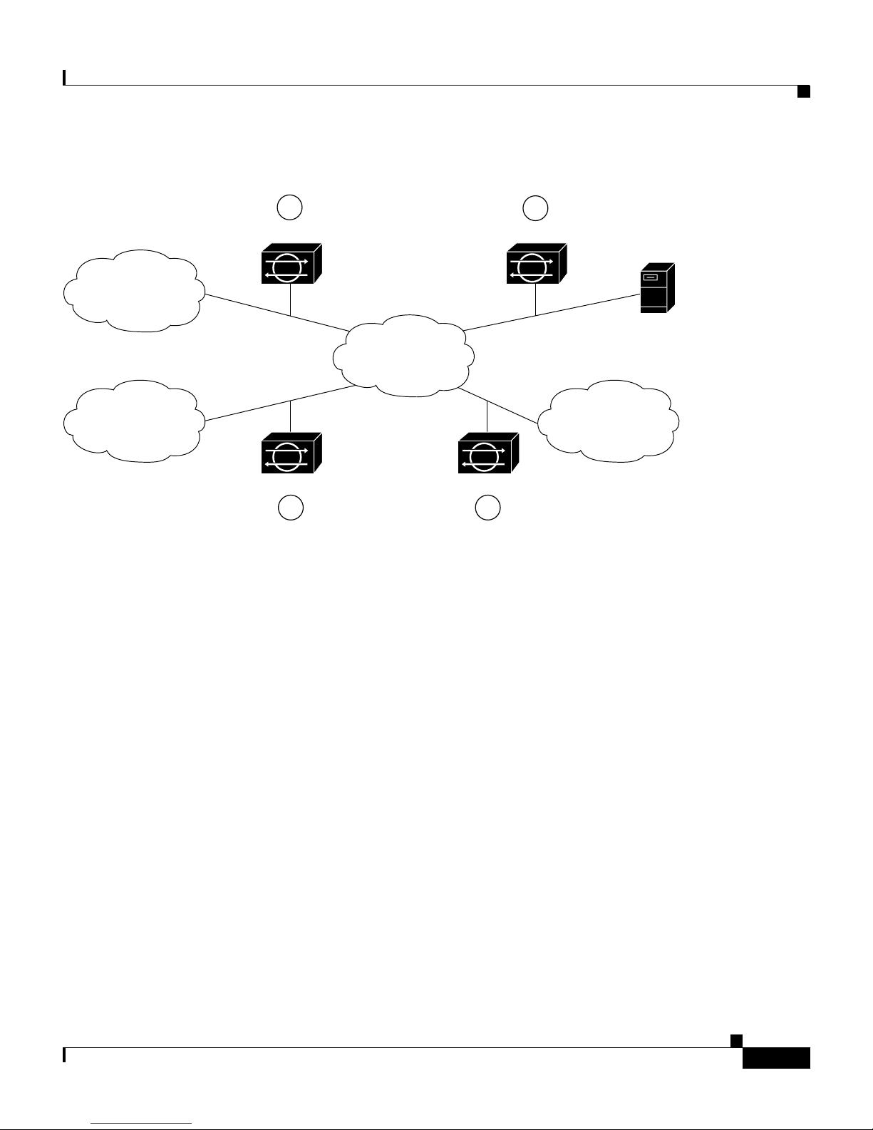
Chapter 1 Introducing the Sensor
Figure 1-1 Major Types of Network Connections
Appliances
Internet
Business
partner
1
Appliance
E-commerce
network
Appliance Appliance
3
Appliance
Dial-up
server
Research and
Development
network
83874
42
In location one, the appliance is placed to monitor traffic between the
E-commerce (protected ) network and the Internet. Th is is referred to as perim eter
protection an d i s the mo st c ommon d ep loymen t fo r an a pplian ce. T his loc at ion
can be shared with firewall protection and is discussed in Placing an Applia nce on
Your Network, page 1-6.
Cisco Intrusion Detection System Appliance and Module Installation and Configuration Guide Version 4.1
78-15597-02
In location two, the appliance is monitoring an extranet connection with a
business partner. Although most companies h ave defined policie s on the u se an d
security of this type of co nnec tion, the re is no guarant ee tha t the network of a
partner is ade qua te ly pr ote cte d. Co nse quent ly, an outsider may e nte r your
network through t his t ype o f co nnect ion . Th ese extra ne t c on necti ons may have
firewalls as well.
In location three, the a pplia nce is monitoring the netwo rk si de o f a r emo te a cc ess
server. Although t his c on necti on m ay be o nly for emp loyee use, it could be
vulnerable to external attack.
In location four, the appliance is monitoring an intr anet connectio n. F or e xa mple,
the protected net work of one depa rtm ent m a y cont ai n an e -com me rce s ite whe re
all the acc ess type s de scr ibe d so far a re r e quire d. T he n etwor k of anot her
department may co ntain c ompany-spec ific researc h and development or oth er
engineering info rmat ion and shou ld be given additional pro tectio n.
1-5
Page 30

Appliances
Determine which segments of the network you want to monitor to determine the
location for the applianc e. Remember, each appliance maintains a securit y policy
configured for the se gme nt it is monitoring . The security policies can be standard
across the organization or unique for each appliance. You may consider changing
your network topology to force traffic across a given monitored network segment.
There are always operational trade-offs when going through this process. The end
result should be a rough idea of the number of appliances required to protect the
desired network.
Placing an Appliance on Your Network
You can place an appliance in front of or behind a firewall. Each position has
benefits and drawbacks.
Placing an appliance in front of a firewall allows the appliance to monitor all
incoming and outgoing network traffic. However, when deployed in this manner,
the appliance does not detect traffic that is internal to the network. An internal
attacker taking advantage of vulnerabilities in network services would remain
undetected by th e extern al ap plian ce (s ee Figure 1-2 on p age 1-7).
Chapter 1 Introducing the Sensor
Cisco Intrusion Detection System Appliance and Module Installation and Configuration Guide Version 4.1
1-6
78-15597-02
Page 31

Chapter 1 Introducing the Sensor
Figure 1-2 Appliance in Front of a Firewall
Appliances
Hostile
network
ISP router
Outermost router
Monitoring interface
Firewall
Protected network
Management host
IDS Appliance
Control interface
97331
Placing an appliance behind a firewall allows it to monitor internal traffic, but it
cannot monitor any policy violations that the firewall rejects (see Figure 1-3 on
page 1-8).
Cisco Intrusion Detection System Appliance and Module Installation and Configuration Guide Version 4.1
78-15597-02
1-7
Page 32

Appliances
Chapter 1 Introducing the Sensor
Figure 1-3 Appliance Behind a Fir e wall
Hostile
network
ISP router
Outermost router
Firewall
Control interface
Management network
Management
host
Deployment Considerations
For the appliance to effectively defend a net work with a rou ter and firewall
configuration, you mu st do th e f oll owing:
• Enable SSH services on the router if available, otherwise, enable Telnet.
• Add the router to the device managem ent list of the applianc e (via th e IDS
manager).
Monitoring interface
Appliance
Protected net
97332
Cisco Intrusion Detection System Appliance and Module Installation and Configuration Guide Version 4.1
1-8
78-15597-02
Page 33

Chapter 1 Introducing the Sensor
• Configure the firewall to permit the following traffic:
Essentially, the firewall implements policy filtering. The appliance captures
packets between the Cisc o router an d the firewall, and can dynamic ally
update the ACLs of the Cisc o r oute r t o d eny u naut horiz ed ac tivity.
Appliances
–
SSH or Telnet traffic from the control interface of the appliance to the
router.
–
Syslog (UDP port 514) tra ffic from the router to the applianc e.
Note T o capture policy violations on the router, the appliance must also
be configured to accept syslog messages.
–
Communications (TCP ports 443 for TLS/SSL and 22 for SSH) between
the appliance and any IDS manager workstation, if the firewall comes
between them.
Note You can also configure the applianc e to mana ge a PIX Firewall
instead of the C is co ro uter.
Appliance Restrictions
The following restrict ions appl y to usin g and opera ting th e appli ance:
• The appliance is not a genera l purpose workstatio n.
• Cisco Systems prohibits using the appliance for anything other than operating
Cisco IDS.
• Cisco Systems prohibits modifying or installing any hardw a re or softw are in
the appliance that i s not part of the normal ope ration of t he Cisco IDS.
Setting Up a Terminal Server
A terminal server is a router with multiple, low speed, asynchronous ports that are
connected to othe r serial d evices. Yo u can use termi nal ser vers to remot ely
manage network eq uipme nt, inc ludi ng app lia nce s.
Cisco Intrusion Detection System Appliance and Module Installation and Configuration Guide Version 4.1
78-15597-02
1-9
Page 34

Appliances
Chapter 1 Introducing the Sensor
T o set up a Cisco terminal server with RJ-45 or hydra cable assembly connections,
follow these s teps :
Step 1 Connect to a terminal server using one of the following methods:
• For the IDS-4215, IPS-4240, an d IPS-4255:
–
For RJ-45 connection s, conne ct a 180/ro llover cable from the co nsole
port on the appliance to a port on the terminal server.
–
For hydra cable assemblies, connect a straight-through patch cable from
the console port on the appliance to a port on the terminal server.
• For all other appliances, connect the M.A.S.H. adapter (part number
29-4077-01) to COM1 on the appl iance and:
–
For RJ-45 connections, connect a 180/rollover cable from the M.A.S.H.
adapter to a port on the terminal server.
–
For hydra cable assemblies, connect a straight-through patch cable from
the M.A.S.H. adapter to a port on the terminal server.
Step 2 Configure the line/port on the terminal server as follows:
a. In enable mode, ty p e th e fo llowing configuration, where # is the line number
of the port to be co nfigur ed:
config t
line #
login
transport input all
stopbits 1
flowcontrol hardware
speed 9600
exit
exit
wr mem
b. If you are configuring a term inal server for an IDS-4215 , IPS-4240 , or
IPS-4255, skip to Step 3.
Otherwise, fo r all o the r s uppo rte d app l ianc es , to d irec t a ll ou t put to the
terminal server, log in to the IDS CLI and type the following commands:
sensor# configure terminal
sensor(config)# display-serial
Cisco Intrusion Detection System Appliance and Module Installation and Configuration Guide Version 4.1
1-10
78-15597-02
Page 35

Chapter 1 Introducing the Sensor
Output is directed to the serial port. Use the no display-serial command to
redirect output to the keyboard/monitor.
Note You can set up a terminal server and use the IDS CLI display-serial
Note There is o nly o ne c on sole por t on a n IDS-4 215 , IPS-4 240 , and
Appliances
command to direct all output from the appliance to the serial port.
This option en able s y ou to v iew system m essage s on a conso le
connected to the serial port, even during the b oot process. When you
use this option, all output is directed to the serial port and any local
keyboard/monitor connection is disabled. However , BIOS and POST
messages are still displayed on the local keyboard/monitor.
IPS-4255; therefore , t he display- serial and no display- serial
commands do not ap ply to thos e platform s.
Step 3 Be sure to properly close a terminal session to avoid unauthorized access to the
appliance.
If a terminal session is not stopped properly, that is, if it does not recei ve an exit(0 )
signal from the application that initiated the session, the terminal session can
remain open. When te rminal sessi ons are not stopped prope rly, authentication is
not performed on t he n ext sessio n that i s op en ed on the s eria l p ort.
Tip Always exit your session and return to a login prompt before terminating
the application used to establish the connection.
Caution If a connection is dropped or termi nated by acci dent, you should re establi sh the
connection and exit normally to prevent unauthorized access to the appliance.
Cisco Intrusion Detection System Appliance and Module Installation and Configuration Guide Version 4.1
78-15597-02
1-11
Page 36

Chapter 1 Introducing the Sensor
Modules
Modules
This section de sc ribe s th e modul es and c onta ins th e foll owing topi cs:
• Introducing the Cisco In trusio n D et ecti on Syst em Ne twork Modu le,
page 1-12
• Introducing the Cisco Catalyst 6500 Ser ies Intrusi on Detection System
Services Module, page 1-14
Introducing the Cisco Intrusion Detection System Network
Module
The Cisco Intrusion De tection Syst em Networ k Module (NM-CIDS ) integrates
the Cisco IDS func ti onal ity i nto a br an ch office route r. With the NM-CIDS, you
can implement full- featured IDS at your remote branch offic es. You can install the
NM-CIDS in any one o f t he ne twork m odule slo ts on the Cisco 26 00, 3 600 , and
3700 series routers. The NM-CIDS can monitor up to 45 Mbps of network traffic.
See Software and Hardware R equ ireme nts , page 7-2 , for a list of supported
routers. Onl y one N M-CI DS i s su ppo rte d per r oute r. Figure 1-4 on page 1-13
shows the IDS router in a br anch office environment.
Cisco Intrusion Detection System Appliance and Module Installation and Configuration Guide Version 4.1
1-12
78-15597-02
Page 37

Chapter 1 Introducing the Sensor
Figure 1-4 NM-CIDS in the Branch Office Router
HQ
Untrusted
network
Modules
Hacker A
outside
26xx/36xx/37/NG
Branch
IDS network
module
Command
and control
Hacker B
Employee
87947
The NM-CIDS has one internal 10/100 Ethernet port that connects to the router’s
backplane. There is a lso one externa l 10/100-based Ethernet port that is u s ed for
device management (manage ment of othe r router s and/or PIX Firewalls to
perform shunning) and command and control of the NM-CIDS by IDS managers .
The NM-CIDS commu nicat es wit h the rou ter to excha nge co ntro l and st ate
information for bri nging up an d shutti ng down the NM-CIDS and t o exchange
version and status information. The NM-CIDS processes packets that are
forwarded from selected interfaces on the router to the IDS interface on the
NM-CIDS. The NM-CIDS analyzes the captured packets and compares them
against a rule set of typical intrusion activity called signatures. If the captured
packets match a defined intrusion pattern in the signatures, the NM-CIDS can take
one of two actions: it can make ACL changes on the router to block the attack, or
it can send a TCP reset packet to the sender to stop the TCP session that is causing
the attack.
Cisco Intrusion Detection System Appliance and Module Installation and Configuration Guide Version 4.1
78-15597-02
1-13
Page 38

Modules
Chapter 1 Introducing the Sensor
In addition to analyzing captured packets to identify malicious activity, the
NM-CIDS can also perf orm IP session logging tha t can be configured as a
response action on a per-signature basis. When the signature fires, session logs are
created over a sp ec ified t ime pe riod in a T CPD ump f orm at . You can view these
logs using Ether eal o r repl ay t he IP se ssion us ing t ool s su ch a s T CP Rep lay.
Note The NM-CIDS does not suppo rt send ing syslog me ssages to a sy slog server if
there is an i ntru sion event, nor d oe s it s uppo rt Sim ple Netwo rk Mana geme nt
Protocol (SNMP) traps.
You can manage and re trieve events from the NM-CIDS through the CLI or
through one of t hes e ID S ma nage rs—IDS Device Manager or M ana geme nt
Center for IDS Sen sors. For instr uc tions o n acc essing I DS do cum entat ion on
Cisco.com, refer to C isco Intr usion Detect ion Syste m (IDS) Hardware and
Software Version 4.1 Document ation Guide that shipped wi th your NM-CI DS.
The IDS requires a reliable time source. All the events (alerts) must have the
correct time stamp, otherwise, you cannot correctly analyze the logs after an
attack. You cannot manually set the time on the NM-CIDS. The NM-CIDS gets
its time from the Cisco router in which it is installed. Router s do not have a battery
so they cannot preserve a time setting w hen they are powered off. Yo u must set
the router’s clock each time you power up or reset the router, or you can configure
the router to use NTP time synchronization. We recommend NTP time
synchronizatio n. You ca n configure ei ther the NM-CIDS it self or the rout er it is
installed in to use NTP time synchronization. See Setting the Time on Sensors,
page 1-18, for more in for mat ion.
Introducing the Cisco Catalyst 6500 Series Intrusion Detection
System Services Module
The Cisco Cata lyst 6 500 Se ries Int rusion De tect ion System Serv ice s M odul e
(IDSM-2) is a switching mod ule th at p erf orms i nt rusio n det ecti on in the Catalyst
6500 series switch. You can use the CLI, IDS Device Manager, or Management
Center for IDS Sensors to configure the IDSM-2. For instructions on accessing the
IDS documentation on Cisco .com , refer to the C isco Intrusion Detection System
(IDS) Hardware and Software Version 4.1 Documentation Guid e that shipped
with your IDSM -2.
Cisco Intrusion Detection System Appliance and Module Installation and Configuration Guide Version 4.1
1-14
78-15597-02
Page 39

Chapter 1 Introducing the Sensor
The IDSM-2 perform s network sen sing—real-time moni toring of ne twork
packets through packet capture and analysis. The IDSM-2 captures network
packets and then reassembles and compares the packet data against attack
signatures indicating ty pical in trusio n ac tivity. Netwo rk tr affic is either copied to
the IDSM-2 based on security VLAN access control lists (VACLs) in the switch
or is copied to the IDSM-2 through the switch’s Switched Port Analyzer (SPAN)
port feature. Thes e method s route user-specified tra ffic to the IDSM-2 based on
switch ports, VLAN s, or traffic type to be inspecte d. (See Figu re 1-5.)
Figure 1-5 IDSM-2 Block Diagram
Modules
Cisco 6500 switch
Source traffic
Destination traffic
Destination traffic
Source traffic
Switch
backplane
Alarms and configuration through
IDS Module command and control port
IDS Management Console
Copied VACL traffic
or SPAN traffic to
IDSM-2 monitor port
IDSM-2
83877
The IDSM-2 searches f or p att er ns of m isuse by examining either the data p ortion
and/or the header portion of network packets. Content-based attacks contain
potentially malicious data in the packet payload, whereas, context-based attacks
contain potentially malicious data in the packet headers.
You can configure the ID SM-2 to ge nerate an a lert whe n it detects po tentia l
attacks. Additionally, you can configure the IDSM-2 to transmit TCP resets on the
source VLAN, genera te an I P log, a nd/or initi at e bloc kin g co unte rmea sur es on a
firewall or other managed device. Alerts are generated by the IDSM-2 through the
Catalyst 6500 series switch backplane to the IDS manager, where they are logged
or displayed on a grap hical us er inte rface.
Cisco Intrusion Detection System Appliance and Module Installation and Configuration Guide Version 4.1
78-15597-02
1-15
Page 40

Supported Sensors
Supported Sensors
Table 1-1 lists the sensors (applia nces and mod ules) th at are supp orted i n this
document and t hat are suppor ted by the most rec ent C isco ID S soft ware.
Note For instructions on how to obtain the most recent Cisco IDS software, see
Obtaining C isco ID S Soft wa re, pa ge 9-1.
Caution Installing the most recent Cisco IDS software (version 4.1) on unsupported
sensors may yield unpredictable results. We do not support software installed on
unsupported pl atfo rm s.
Chapter 1 Introducing the Sensor
Table 1-1 Supported Sens ors
Model Name Part Number Optional Interfaces
Applianc es
IDS-4210 IDS-4210
IDS-4210-K9
IDS-4210-NFR
IDS-4215 IDS-4215-K9
IDS-4215-4FE-K 9
—
—
—
IDS-4FE-INT=
—
IDS-4220 IDS-4220-E —
IDS-4230 IDS-4230-FE —
IDS-4235 IDS-4235-K9 IDS-4FE-INT=
IDS-4250 IDS-4250-TX-K9
IDS-4FE-INT=,
IDS-4250-SX-INT=,
IDS-XL-INT=
IDS-4250-SX-K 9
IDS-XL-INT=
IPS-4240 IPS-4240-K9 —
Cisco Intrusion Detection System Appliance and Module Installation and Configuration Guide Version 4.1
1-16
IDS-4250-XL- K9
—
78-15597-02
Page 41

Chapter 1 Introducing the Sensor
Table 1-1 Sup ported Sensors (continued)
Model Name Part Number Optional Interfaces
Applianc es
IPS-4255 IPS-4255-K9 —
Network Module s
NM-CIDS NM-CIDS-K9 —
Services Modules
IDSM-2 WS-SVC-IDSM2-K9 —
Note The IDS-4215-4FE -K9 is the IDS-42 15-K 9 with the opti onal 4FE card
(IDS-4FE-INT=) installed at the factory.
Supported Se nso rs
The following IDS ap pli ance m odel s a re l egacy models and ar e n ot sup por ted in
this document:
• NRS-2E
• NRS-2E-DM
• NRS-2FE
• NRS-2FE-DM
• NRS-TR
• NRS-TR-DM
• NRS-SFDDI
• NRS-SFDDI-DM
• NRS-DFDDI
• NRS-DFDDI-DM
• IDS-4220-TR
• IDS-4230-SFDDI
• IDS-4230-DF DDI
Cisco Intrusion Detection System Appliance and Module Installation and Configuration Guide Version 4.1
78-15597-02
1-17
Page 42

Setting the Time on Sensors
Note The WS-X6381, the IDSM, is a legacy model and is not supported in this
document.
Note The IDS-4210 and ID S-4220 -E r equ ire m em ory u pgrad es to su ppo rt th e late st
IDS software . See Up gra ding t he M e mory, page 2-3, for more inf orm a tion .
Setting the Time on Sensors
The sensor requires a reliable time source. All events (alerts) must have the
correct GMT an d loca l time sta mp, othe rwise , you can not corre ctly analyze the
logs after an attack. When you initialize your sensor, you set up the time zones
and summer time settings. See Initializing the Sensor, page 10-2, for more
information.
Chapter 1 Introducing the Sensor
Here is a summary of ways to set the time on sensors:
• For appliances
–
Use the clock set command to set the time. This is the default.
Refer to Cisco Intrusion Detection System Command Reference Version
4.1 for information on the clock set command.
–
Use Network Timing Protocol (NTP).
You can configure you r applianc e to get its time from an N TP time
synchronization so urce . See Configur ing a Cisco Route r to be an NTP
Server, page 10-22. You will need the NTP server IP address, the NTP
key ID, and the NTP key value. You can set up NTP on the applia nce
during initialization or you can configure NTP later. See Configuring the
Sensor to Use an NTP Server as its Time Source, page 10-21, for mo re
information.
Note We re commend that you use an N TP time synchroni zatio n
source.
Cisco Intrusion Detection System Appliance and Module Installation and Configuration Guide Version 4.1
1-18
78-15597-02
Page 43

Chapter 1 Introducing the Sensor
• For IDSM-2
Caution Be sure to set the time zone and summertime settings on both the switch and the
IDSM-2 to ensure that th e GMT time settings a re correct. The I DSM2’s lo cal time
will be incorrect if the timezone and/or summertime settings do not match
between the ID SM-2 an d the s witc h.
Setting the Time on Sensors
–
The IDSM-2 can automatically synchronize its clock with the switch
time. This is the default.
Note The GMT time is synchronized between the switch and the
IDSM-2. The time zone and summer time settings are not
synchronized between the switch and the IDSM-2.
–
Use NTP.
You can configure you r IDSM-2 to get its time from a n NTP time
synchronization source. See Configuring a Cisco Router to be an NTP Server,
page 10-22. You will need the NTP server IP address, the NTP key ID, and
the NTP key value. You can configure the ID SM- 2 to use NTP d urin g
initialization or you can set up NTP later. See Configuring the Sensor to Use
an NTP Server as its Time Source, page 10-21, for more information.
Note We reco mmend that you use an NTP tim e synchroniz ation sourc e.
• For NM-CIDS
–
The NM-CIDS can auto matic ally syn chron ize its clock with the cl ock in
the router chassis in which it is installed (parent router). This is the
default.
Note The GMT time is synchronized between the parent router and the
NM-CIDS. The time zone and summer time settings are not
synchronized between the parent router and the NM-CIDS.
Cisco Intrusion Detection System Appliance and Module Installation and Configuration Guide Version 4.1
78-15597-02
1-19
Page 44

Installation Preparati on
Caution Be sure to set the time zone and summertime settings on both the parent router
Chapter 1 Introducing the Sensor
and the N M- CID S to e ns u re tha t th e G M T ti me se t tin gs ar e co rr ec t. Th e
NM-CIDS’s lo cal time will be incorrect if the timezone and/or summertime
settings do not match between the NM-CIDS and the router.
–
Use NTP.
You can configure you r NM-CID S to get its time fro m an NTP ti me
synchronization sourc e, such as a Cisc o router othe r than the pare nt router.
See Configuring a Cisco Router to be an NTP Server, page 10-22. You will
need the NTP server IP address, the NTP key ID, and the NTP key value. You
can configure the NM-CIDS to use NTP du ring initial ization or you can set
up NTP later. See Configuring the Sensor to Us e an NTP Server as its Time
Source, page 10-21, for more information.
Note We reco mmend that you use an NTP tim e synchroniz ation sourc e.
Installation Preparation
To prepare for installing sensors, follow these steps:
Step 1 Review the safety precautions outlined in the Regulatory Compliance and Safety
Information for the Cisco Int rusion Detec tion System 4200 Series Ap pliance
Sensor that ship ped w ith you r sens or.
Step 2 To familiarize yourself with the location of IDS documentation on Cisco.com,
read the Cisco Intrusion Detection System (IDS) Hardware and Software Version
4.1 Documentat ion Gui de th at shipped with your sensor.
Step 3 Obtain the Release Notes for the Cisc o Intrusion De tection Syst em Version 4. 1
from Cisco.com and completely read them before proceeding with the
installation.
Step 4 Unpack the sensor.
Step 5 Place the sensor in an ESD-controlled environment.
See Working i n an E SD E nvironment, pa ge 1-21, for the proce dure.
Cisco Intrusion Detection System Appliance and Module Installation and Configuration Guide Version 4.1
1-20
78-15597-02
Page 45

Chapter 1 Introducing the Sensor
Step 6 Place the sensor on a stable work surface.
Step 7 Refer to the chapt er tha t pertains to yo ur sensor mode l.
Working in an ESD Enviro nment
W ork on ESD-sensitive parts only at an approved static-safe station on a grounded
static dissipative work surface , for exa mple , an E SD workbe nch or sta tic
dissipative mat.
To remove and replace components in a sensor, follow these steps:
Step 1 Remove all static-generating items from your work area.
Working in an ES D Env iro nm ent
Step 2 Use a s tat ic d issipative work surfa ce a nd w ris t strap.
Note Disposable wrist straps, typically those included with an upgrade par t, are
designed for o ne t ime u se.
Step 3 Attach the wrist strap to your wrist and to the terminal on the work surface. If you
are using a disposable wrist str ap, connect t he wris t strap direc tly to an unp ainted
metal surface of the chassis.
Cisco Intrusion Detection System Appliance and Module Installation and Configuration Guide Version 4.1
78-15597-02
1-21
Page 46

Working in an ESD En vironment
Chapter 1 Introducing the Sensor
Copper foil
D
O
N
O
T
I
N
S
T
A
L
L
I
N
T
E
R
F
A
C
E
C
A
R
D
S
W
I
T
H
P
O
W
E
R
A
P
P
L
I
E
D
1
0
0
M
L
b
in
p
s
k
F
D
X
1
0
0
M
b
p
s
L
in
k
F
1
0
/1
0
0
E
T
H
E
R
N
E
T
0
/0
DX
1
0
/1
0
0
E
T
H
E
R
N
E
T
0
/0
PIX-515
F
AIL
O
V
E
R
C
O
N
S
O
L
E
24304
Step 4 Connect the work surface to the chassis using a grounding cable and alligator clip.
Caution Always follow ESD-prevention procedures whe n removi ng, r epla c ing, or
repairing component s.
Note If you are upgrading a component, do not remove the component from the
ESD packaging until you are ready to install it.
Cisco Intrusion Detection System Appliance and Module Installation and Configuration Guide Version 4.1
1-22
78-15597-02
Page 47

CHAPTER
2
Installing the IDS-4210
This chapter describes the IDS-4210 and how to install it and its accessories.
Note IDS-4215 replaces the IDS-421 0, which will no lon ger be sold after July 2 003.
Note If you purchased an IDS-4210 before July 2003, you must upgrade the memory to
256 MB to install Cisco IDS 4.1. See Upgrading the Memor y, page 2-3 for more
information. If yo u pur ch ase an I DS-421 0 dur ing Jul y, it comes from the factory
with the mem or y u pgr ad e an d versi on 4.1 i nsta ll ed.
This chapter contains the following sections:
• Front Panel Features and Ind icators, page 2-1
• Upgrading the Me mory, page 2-3
• Installing the IDS-4 210, page 2-5
• Installing the Acce ssories, pa ge 2-8
Front Panel Features and Indicators
Figure 2-1 on page 2-2shows the front panel indicators on the IDS- 4210.
Cisco Intrusion Detection System Appliance and Module Installation and Configuration Guide Version 4.1
78-15597-02
2-1
Page 48

Front Panel Features an d Indicators
Figure 2-1 Front Panel Features
LAN 1 activity/link
indicator
System fault indictor
Power indicator
LAN 2 activity/link
indicator
Chapter 2 Installing the IDS-4210
87951
1
Hard-disk drive
activity indicator
2
Table 2-1 describes the appear ance and functi on of the fron t panel ind icators.
Table 2-1 Front Panel Indicators
Indicator Color Function
Power Green Lights up when the sy stem is connecte d to
an AC power source; blinks when the
system is in sleep mode.
System fault Amber Blinks during system st art up or w hen a
system fault is detected.
Hard-disk drive activity Green Blinks when hard- disk drive activity
occurs.
LAN1 activity/link Amber Lights up when the LAN1 connector is
linked to an Ethernet port; blinks when
activity occurs on this channel.
LAN2 activity/link Amber Lights up when the LAN2 connector is
Cisco Intrusion Detection System Appliance and Module Installation and Configuration Guide Version 4.1
2-2
linked to an Ethernet port; blinks when
activity occurs on this channel.
78-15597-02
Page 49

Chapter 2 Installing the IDS-42 10
Upgrading the Memory
The IDS-4210, IDS-42 10-K9, ID S-4210 -NFR, and IDS-4 220-E sensors must
have 512 MB RAM to sup por t Ci sco IDS 4 .1 sof tware. If y ou ar e up gra ding an
existing IDS-4210, ID S-4210 -K 9, I DS-421 0-NF R, o r IDS-4 220-E se nsor t o
version 4.1, you m ust inser t addi tiona l D u al In- line Me m ory M odu les (DIM M s)
(see part numbers below for supporte d DIMMs) to upgrade the me mory to the
required 512 MB minim um.
The following D IMM s a re s uppo rte d:
• For IDS-4210 sensors, you insert one additional 256 MB DIMM (Part number
IDS-4210-MEM-U ) for a tot al of 512 MB.
• For the IDS-4220-E se nso r, you insert two ad diti onal 128 MB D IMM s (Part
number IDS-4220-M EM-U) for a total of 512 MB.
Upgrading the Memory
Note Do not install an unsupported DIMM. Doing so nullifies your warranty.
Caution Be sure to read the safety warnings in the Regulatory Compliance and Safety
Information for the Cisco Int rusion Detec tion System 4200 Series Ap pliance
Sensor and follow proper safety pr oced ures when pe rform ing thes e steps.
To upgrade the memory, follow these steps:
Step 1 Log in to the CLI.
Step 2 Prepare the appliance to be powered off:
sensor# reset powerdown
Wait for t he power down m essage b efor e co nti nuing w ith St ep 3.
Note You can also power down the sensor from IDM or IDS MC.
Step 3 Power off the appliance.
Step 4 Remove the power cord and other cables from the appliance.
Step 5 Place the appliance in an ESD-controlled environment.
Cisco Intrusion Detection System Appliance and Module Installation and Configuration Guide Version 4.1
78-15597-02
2-3
Page 50

Upgrading the Memory
Step 6 Remove the chassis cover by unscrewing the screw(s) on the front of the cover and
Step 7 Locate the DIMM sockets and select an empty DIMM socket next to the existing
Chapter 2 Installing the IDS-4210
See Working i n an E SD E nvironment, pa ge 1-21, for more infor mati on.
sliding the cover straight back.
Note IDS-4210 sensors have a single screw on the front cover. IDS-4220
sensors have three screws spaced evenly across the fron t c over.
DIMM.
Note On IDS-4210 sensor s, the existing DIMM is inst alled in socket 0. The
angled position of the DIMM sockets make installing an additional
DIMM in socket 1 di fficult if a DIMM occupies so cket 0. Therefore, you
should first remove the existing DIMM from socket 0, pla ce the new
DIMM in socket 1, and then place the existing DIMM back in socket 0.
DIMM
41167
Bank 3
Bank 2
Bank 1
Bank 0
Step 8 Locate the ejector tabs on either side of the DIMM socket. Press down and out on
tabs to open the slot in the socket.
Cisco Intrusion Detection System Appliance and Module Installation and Configuration Guide Version 4.1
2-4
78-15597-02
Page 51

Chapter 2 Installing the IDS-42 10
Step 9 Install the new DIMM (one at a time if you are installing more than one), by
positioning the DIMM into the socket and pressing it in to place.
Note Do not force the DIMM into the socket. Alignment keys on the DIMM
Step 10 Replace the chassis cover and reconnect the power.
Step 11 Power on the sensor and ensure the new memory total is correct.
Note If the memory total does not reflect the added DIMMs, repeat Steps 1
Installing the IDS-4210
ensure that it only fits in the socket one way. If you need additional
leverage, you can gen tly pr es s down o n the DIM M w ith yo ur t hum bs
while pulling up on the ejector tabs.
through 4 to ensure the DIMMs are seated correctly in the socket.
Installing the IDS-4210
Warning
Caution Be sure to read the safety warnings in the Regulatory Compliance and Safety
Note If you purchased an IDS-4210 before July 2003, you must upgrade the memory to
Only trained and qualified personnel should be allowed to install, replace, or
service this equipment. Statement 1030
Information for the Cisco Int rusion Detec tion System 4200 Series Ap pliance
Sensor and follow proper safety pr oced ures when pe rform ing thes e steps.
256 MB to install Cisco IDS 4.1. See Upgrading the Memory , page 2-3, for more
information. If yo u pur ch ase an I DS-421 0 dur ing Jul y, it comes from the factory
with the mem or y u pgr ad e an d versi on 4.1 i nsta ll ed.
Cisco Intrusion Detection System Appliance and Module Installation and Configuration Guide Version 4.1
78-15597-02
2-5
Page 52

Installing the IDS- 4210
Step 1 Position the a pplianc e on the network .
Step 2 Attach the power cord to the appliance and plug it in to a power source (a UPS is
Step 3 Use t he du al seri al com mu ni cat ion c able (P N 72 -18 47- 01, in cl ud ed in the
Chapter 2 Installing the IDS-4210
To inst all the IDS-42 10 on your net work, follow these steps:
See Placing an Appliance on Y our Network, page 1-6 for information on the best
places to position an appliance.
recommende d).
Note When you first plug an IDS-4210 into a power source, it powers on
momentarily a nd the n powers off leaving the Ne twork In terfa ce C ar d
(NIC) link lights lit. Thi s is normal behavior. Press the power switch to
boot the system into operation.
accessory kit) to attach a laptop to the COM1 port of the IDS appliance (see
Table 2-2 for a list of the terminal settings), or connect a ke yboard and monitor to
the appliance.
Table 2-2 Terminal Settings
Terminal Setting
Bits per second 9600
Data bits 8
Parity None
Stop bits 1
Flow control Hardware or RTS/CTS
Caution We recommend that you use the dual serial communication cable (PN
72-1847-01, incl uded in the ac cessory kit ) rather th an a keyboard and mon itor,
because some keyboards and monitors may be incompatible with the appliance.
Cisco Intrusion Detection System Appliance and Module Installation and Configuration Guide Version 4.1
2-6
78-15597-02
Page 53

Chapter 2 Installing the IDS-42 10
Note You can use a 180/rollover or straight-through patch cable to connect the
Step 4 Attach the network cables.
AC power
Mouse
(unused)
Installing the IDS-4210
appliance to a p ort on a t ermi nal server wi th RJ- 45 or hydra c abl e
assembly conne ction s. Us e a M.A .S.H ad apte r (p art num ber 29-40 77-0 2)
to connect the appropriate cable to a port on the terminal server. See
Setting Up a Terminal Server, page 1-9 for the instructions for setting up
a terminal server.
Command
and Control
interface: int1
COM1
83723
Keyboard Sniffing
USB
(unused)
interface: int0
Video
• int0 is the sensing port.
• int1 is the command an d control port.
Step 5 Upgrade the memory on the appliance.
See Upgrading the Memo ry, page 2-3, for the procedure.
Caution You must upgrade the memory on the IDS-4210 to a minimum of 512 MB before
you can insta ll t he m ost re cent C isco ID S soft ware vers ion.
Step 6 Power on the appliance.
Step 7 Initializ e yo ur a pplian ce.
See Initializing the Sensor, page 10-2, for the procedure.
Step 8 Upgrad e your appl iance to the latest Cisco IDS soft ware.
See Obtaining Cisco IDS So ftware , page 9-1, for th e procedu re.
Cisco Intrusion Detection System Appliance and Module Installation and Configuration Guide Version 4.1
78-15597-02
2-7
Page 54

Installi n g th e Accessories
Step 9 Assign the interfaces.
See Assigning and Enabli ng t he Se nsin g Int erfac e, p age 10-9, for t he pr oc ed ure.
You are now ready to configure i ntrusi on detect ion on you r applianc e.
Installing the Accessories
You can install a be zel, and center or fro nt mounting brackets for yo ur IDS-4210.
This section contains the following topics:
• Accessori es Pa ck ag e Con te nt s, p ag e 2-8
• Installing an d R emoving the B ezel, p age 2-9
Chapter 2 Installing the IDS-4210
• Installing Cen ter Moun t Brac kets , pa ge 2-9
• Installing Front Moun t Brackets, page 2-11
Accessories Package Contents
The following items are shipped in the accessories package for the IDS-4210:
• Cisco IDS-4210 be zel
• Power cable
• Network patch cable
• Computer interconnection cable
• Dual serial communication cable
• Rack mounting b racket s
Cisco Intrusion Detection System Appliance and Module Installation and Configuration Guide Version 4.1
2-8
78-15597-02
Page 55

Chapter 2 Installing the IDS-42 10
• Documentation and software
–
Cisco IDS recovery/upgrade CD
–
Cisco Documentation CD
–
Cisco Intrusion Detection System (IDS) Hardware and Software Version
4.1 Documentat ion Gui de
–
Regulatory Compliance and Safety In formati on for the Cisco Intrusion
Detection System 42 00 Series Appl iance Senso r
Installing and Removing the Bezel
You can install a Cisco bezel for the IDS-4210.
To install and remove the bezel on the IDS-4210, follow these steps:
Installin g the Ac ces sor i es
Step 1 To insert the bezel on the appliance, follow these steps:
a. Align the bottom tabs on the bezel with the slots on the appliance.
b. Align the side tabs on the bezel with the slots on the appliance.
c. Press the bezel into the appliance.
Step 2 To remove the bezel from the appliance, press the side tabs and pull.
Installing Center Mount Brackets
You need the following tools and supplies to install the brackets in a two-post,
open-frame re lay rack :
• #2 Phillips screwdriver
• Masking tape or felt-tip pen to mark the mounting holes to be used
To install the center mount brackets in a two-post, open-frame relay rack, follow
these step s:
Step 1 Determ ine whe re you want t o place yo ur appl iance .
Step 2 Mark the upp er and l ower moun ting p osi tions on the two posts.
Cisco Intrusion Detection System Appliance and Module Installation and Configuration Guide Version 4.1
78-15597-02
2-9
Page 56

Installi n g th e Accessories
Step 3 Locate one of the two brac kets and align it ov er t he two thre aded holes on t he side
of the appliance (see Figure 2-2).
Figure 2-2 Installing Center Mount Brackets
Pan-head
Phillips screws
Chapter 2 Installing the IDS-4210
Pan-head
Phillips screws
(2 per bracket)
LINK
100M
bps LIN
0
K
1
100M
2
3
bps
D
R
IV
E 0
D
R
IV
E
CO
N
S
ETH
E
R
NET
0
1
E
THE
RN
E
T 1
SC
SI LVD
ON
LY
D
RIVE 0
D
RIVE 1
50623
Step 4 Secure the bracket to the appliance chassis using two screws (see Figure 2-2).
Step 5 Repeat Step 4 to install the remaining bracket on the other side of the appliance.
Step 6 Lift the appliance into position between the two posts with the hole in the
mounting bracket aligned one hole above the mark you made in the two posts (see
Figure 2-2).
Cisco Intrusion Detection System Appliance and Module Installation and Configuration Guide Version 4.1
2-10
78-15597-02
Page 57

Chapter 2 Installing the IDS-42 10
Step 7 Secure the appliance to the rack using a screw through the mounting bracket to
the front of the left and right posts (see Figure 2-2 on page 2-10).
Installing Front Mount Brackets
Make sure you have the fo llowing su ppli es (foun d in t he f ro nt m oun t br ac ket
assembly kit) and tools to install the front mount brackets in a two-post,
open-frame re lay rack :
• Two chassis supp ort brackets
• Two r ack- mo unti ng brac ket s
• Six screws
Installin g the Ac ces sor i es
• #2 Phillips screwdriver
Note The front mount bracket assembly is not intended for use as a slide rail system.
The server must be firmly attached to the rack, as shown in Fig ure 2-3 on
page 2-12.
Cisco Intrusion Detection System Appliance and Module Installation and Configuration Guide Version 4.1
78-15597-02
2-11
Page 58

Installi n g th e Accessories
Figure 2-3 Front Mount Brackets
Chapter 2 Installing the IDS-4210
Pan-head
Phillips screws
Pan-head
Phillips screws
(to rack)
LIN
K
100Mbp
sLIN
0
K
1
100M
2
3
bps
DR
IV
E 0
D
RIVE
CO
N
S
ETH
E
R
NET
0
1
ET
HE
RN
E
T 1
SC
SI LV
D ON
LY
D
RIVE 0
D
RIVE 1
55150
Caution The chassis support brackets in cluded in this kit are rat ed for 50 po unds of load
per pair of brackets for ge neral use for 10,000 cycles of opening an d closing .
Higher cycles or frequency will lower the load rating. The chassis support
brackets are m e an t t o s uppo rt th e w eigh t of on l y o ne appl ia nce.
Cisco Intrusion Detection System Appliance and Module Installation and Configuration Guide Version 4.1
2-12
78-15597-02
Page 59

Chapter 2 Installing the IDS-42 10
To install the front mount brackets, follow these steps:
Step 1 Make sure the appliance is turned off and is not plugged in to an electrical outlet.
Step 2 Use the screws provided to attach one chassis support bracket to each side of the
appliance. Use three screws on each side.
Step 3 Use the screws provided with the rack to attac h the rack mounting brac kets to the
rack.
Step 4 Slide the cha ssis support bra ckets on the appli ance int o the rack mounting
brackets attached to the rack.
Step 5 Use the bolts provided with the rack to fasten the appliance’s front flanges to the
rack.
Note When you are d one , t he a pp lianc e shoul d not s lid e on t he c ha nnel bar.
Installin g the Ac ces sor i es
Cisco Intrusion Detection System Appliance and Module Installation and Configuration Guide Version 4.1
78-15597-02
2-13
Page 60

Installi n g th e Accessories
Chapter 2 Installing the IDS-4210
Cisco Intrusion Detection System Appliance and Module Installation and Configuration Guide Version 4.1
2-14
78-15597-02
Page 61

CHAPTER
3
Installing the IDS-4215
The Cisco IDS-4215 ca n monito r up to 80 Mbps of ag gregate tra ffic and is
suitable for T1/E1 and T3 environments. With the addition of the four-port fast
Ethernet (4FE) c ard, the IDS- 4215 supp orts five monitoring interfaces
(10/100BASE-TX), which provide simultaneous protection for multiple subnets.
Note The 80-Mbps performance for the IDS-4215 is based on the following conditions:
aggregation of t r affic from al l five monitoring i nte rface s, 800 new TCP
connections per second, 800 HTTP transactions per second, average packet size
of 445 bytes, system runn in g Cis co ID S 4.1 se nso r soft ware.
Cisco Intrusion Detection System Appliance and Module Installation and Configuration Guide Version 4.1
78-15597-02
The monitoring interfaces and the command and control interface are all
10/100BASE-TX.
This chapter describes the IDS-4215 and how to install it. It also describes the
accessories and how to install them.
This chapter contains the following sections:
• Front and Back Panel Feat ur es , p ag e 3-2
• Specifications, page 3-4
• Accessories, page 3-5
• Surface Mounting, page 3-6
• Rack Mountin g, pa ge 3-7
• Installing the IDS-4 215, page 3-9
• Removing and Replacing the Chassis Cover, page 3-12
3-1
Page 62

Front and Back Panel Features
• Removing and Repla cin g th e IDE H ard- Disk Drive, page 3-17
• Removing and Replacing the Com pact Flash Device, page 3-21
• Removing and Installing the 4FE Card, page 3-25
Front and Back Panel Features
This section describes the IDS-4215 front and back panel features and indicators.
Figure 3-1 shows the front view of the IDS-4215.
Figure 3-1 IDS-4215 Front Panel Features
Chapter 3 Installing the IDS-4215
CISCO IDS-4215
Intrusion Detection Sensor
POWER
ACT
NETWORK
Table 3-1 describes the front pan el indicator s on the ID S-4215 .
Table 3-1 Front Panel Indicators
Indicator Description
POWER Lights up wh en power suppl y is ru nning .
ACT Lights up when the unit has completed power-up self-test
and has started the operati ng system an d applicatio n
software loading process.
NETWORK Blinks when network traf fic is passing over either of the two
built-in Ethernet ports; does not indicate traffic on any of the
four ports of the 4FE card.
87925
Cisco Intrusion Detection System Appliance and Module Installation and Configuration Guide Version 4.1
3-2
78-15597-02
Page 63

Chapter 3 Installing the IDS-42 15
Figure 3-2 shows the back view of the I DS-42 15.
Figure 3-2 IDS-4215 Back Panel Features
Front and Back Panel Feat ures
Empty PCI
slot
int2
int3
int4
USB
(unused)
10/100 ETHERNET 0
int5
int0
10/100 ETHERNET 1
int1
CONSOLE
USB
Console
Off/on
87926
Power
connector
The built-in Eth ernet ports ha ve three in dicators per port and the 4FE card has tw o
indicators per port. Figure 3-3 shows the back panel in dicat ors.
Figure 3-3 IDS-4215
Indicators
Indicators
Cisco Intrusion Detection System Appliance and Module Installation and Configuration Guide Version 4.1
78-15597-02
100Mbps
ACT
10/100 ETHERNET 0
100Mbps
LINK
ACT
10/100 ETHERNET 1
LINK
USB
CONSOLE
119585
Table 3-2 lists the back panel indicators.
Table 3-2 Back Panel Indicators
Indicator Description
Built-in Et hern et —
100 Mbps Ligh ts u p w h en t he port is ru nni ng in 10 0-Mbp s mode ;
off when it is running in 10-Mbps mode.
Link Lights up when the port is connected to another Ethernet
port and tr affic can be pas sed be t wee n them .
ACT Blinks when network traffic is being received on the port.
3-3
Page 64

Specifications
Table 3-2 Back Panel Indicators (continued)
Indicator Description
4FE Card —
LINK/activity Lights up when the port is connected to another
100 Mbps Ligh ts u p w h en t he port is ru nni ng in 10 0-Mbp s mode ;
Specifications
Chapter 3 Installing the IDS-4215
operational Et hernet port but no traffic is being passed
between them; blinks off when Ethernet packets are being
received.
off when the port is ru nnin g i n 10-M bps mo de.
Table 3-3 lists the specifications for the IDS-4215.
Table 3-3 IDS-4215 Specifications
Dimension s and Weight
Height 1.72 in. (4.3 7 c m)
Width 16.8 in. (42.72 cm)
Depth 11 .8 in. (29.97 cm)
We ight 11.5 lb (4.11 kg)
Form factor 1 RU, standard 19-inch rack-mountable
Expansion Two 32-bit/33-MHz PCI slots
Power
Autoswitching 100V to 240V AC
Frequency 50 to 60 Hz, single phase
Operati ng c urr en t 1.5 A
Steady state 50 W
Maximum peak 65 W
Maximum heat dissipa tio n 410 BTU/hr, full power usage ( 65W )
Cisco Intrusion Detection System Appliance and Module Installation and Configuration Guide Version 4.1
3-4
78-15597-02
Page 65

Chapter 3 Installing the IDS-42 15
Table 3-3 IDS-4215 Specifications (continued)
Environment
Temperature Operatin g +41°F to +104°F (+5°C to +40°C)
Relative humidity Operating 5% to 95 % (non con densi ng )
Altitude Operating 0 to 9843 ft (3000 m)
Shock Operating 1.14 m/sec (45 in./sec) 1/2 si ne input
Vibration 0.41 Grms2 (3- 500 H z) r an dom i np ut
Accessories
Nonoperating -13°F to +158°F (-25°C to +70°C)
Nonoperating 5% to 95% (noncon densing )
Nonoperating 0 to 15 ,00 0 f t ( 4750 m )
Nonoperating 30 G
Acoustic noi se 54 dB a ma ximu m
Note Only one PCI expansi o n slo t c an be u sed for the 4FE ca rd. We recommend you
install the 4FE card in the lower PCI expansion slot.
Accessories
Warning
IMPORTANT SAFETY INSTRUCTIONS
This warning symbol means danger. You are in a situation that could cause
bodily injury. Before you work on any equipment, be aware of the hazards
involved with electrical circuitry and be familiar with standard practices for
preventing accidents. Use the statement number provided at the end of each
warning to locate its translation in the translated safety warnings that
accompanied this device. Statement 1071
SAVE THESE INSTRUCTIONS
Cisco Intrusion Detection System Appliance and Module Installation and Configuration Guide Version 4.1
78-15597-02
3-5
Page 66

Surface Mounting
Chapter 3 Installing the IDS-4215
Warning
Only trained and qualified personnel should be allowed to install, replace, or
service this equipment. Statement 1030
The IDS-4215 acc essor ies kit cont ai ns th e foll owing:
• DB25 connector
• DB9 connecto r
• Rubber mounting feet
• Rack mounting k it—screws, washers, and metal bracket
• RJ45 console cable
• 6-ft Ethernet cable
Surface Mounting
If you are not rack mounting the IDS-4215, you must attach the rubber feet to the
bottom of the IDS-4 215 a s shown in Fi gure 3-4 on page 3-7. The rubber feet are
shipped in the accessories kit.
Cisco Intrusion Detection System Appliance and Module Installation and Configuration Guide Version 4.1
3-6
78-15597-02
Page 67

Chapter 3 Installing the IDS-42 15
Figure 3-4 Surface Mounting the ID S-4215
Rack Mounting
Fan
Caution For proper cooling and reliability, the rubber feet must be installed on the
IDS-4215 when it is on a flat surface. The rubber feet allow proper airflow around
the IDS-4215 and they also absor b vibratio n so that the ha rd-disk dr ive is less
impacted.
Rack Mounting
Warning
T o prevent bo dily injury when mounting or servicing this unit in a rack, you must
take special precautions to ensure that the sys tem remains stable. The
following guidelines are provided to ensure your safety: This unit should be
mounted at the bottom of the rack if it is the only unit in the rack. When
mounting this unit in a partially filled rack, load the rack from the bottom to the
24301
Unused
Cisco Intrusion Detection System Appliance and Module Installation and Configuration Guide Version 4.1
78-15597-02
3-7
Page 68

Rack Mounting
Chapter 3 Installing the IDS-4215
top with the heaviest component at the bottom of the rack. If the rack is provided
with stabilizing devices, install the stabilizers before mounting or servicing the
unit in the rack.
If you are installi ng the 4FE ca rd in the ID S-4215 , do not instal l the mo unting
brackets until after you have installed the 4FE card.
Note You must remove the chassis cover of the IDS-4215 to properly install or remove
the 4FE card. See Removing and Replacing the Chassis Cover, page 3-12, for
information on how to r emove and re pla ce the c has sis cover. See Installing the
4FE Card, page 3-27, for information on installing the 4F E card in the IDS-4215 .
To ra ck mount the ID S-4215 , follow these steps :
Step 1 Use the supplied screws to attach the bracket to the appliance.
You can attach the brackets to the holes near the front of the appliance.
CISCO IDS-4215
Intrusion Detection Sensor
104185
Step 2 Attach the appliance to the equipment rack.
Cisco Intrusion Detection System Appliance and Module Installation and Configuration Guide Version 4.1
3-8
78-15597-02
Page 69

Chapter 3 Installing the IDS-42 15
Installing the IDS-4215
P
O
W
E
R
A
C
T
N
E
T
W
O
R
K
CISCO IDS-4215
Intrusion Detection Sensor
Installing the IDS-4215
Warning
Caution Be sure to read the safety warnings in the Regulatory Compliance and Safety
Only trained and qualified personnel should be allowed to install, replace, or
service this equipment. Statement 1030
Information for the Cisco Int rusion Detec tion System 4200 Series Ap pliance
Sensor and follow proper safety pr oced ures when pe rform ing thes e steps.
104186
Cisco Intrusion Detection System Appliance and Module Installation and Configuration Guide Version 4.1
78-15597-02
3-9
Page 70

Installing the IDS- 4215
Step 1 Position the a pplianc e on the network .
Step 2 Attach the power cord to the appliance and plug it into a power source (a UPS is
Step 3 Connect the cable so th at yo u have either a DB-9 or DB-2 5 co nn ecto r on o ne en d
Chapter 3 Installing the IDS-4215
To inst all the IDS-42 15 on your net work, follow these steps:
See Placing an Appliance on Y our Network, page 1-6, for information on the best
places to position an appliance.
recommende d).
as required by the s eria l p ort for y our com put er, and th e othe r end i s the RJ- 45
connector.
10/100 ETHERNET 1
USB
CONSOLE
Computer serial port
Console
DB-9 or DB-25
port (RJ-45)
RJ-45 to
DB-9 or DB-25
serial cable
(null-modem)
Note Use the console por t to conne ct to a co mputer to enter c onfiguration
commands. Loca te the serial cable from the accessory kit. The ser ial cable
assembly consis ts of a 180/rol lover cable with RJ-45 c onnec tors (DB- 9
connector ad ap ter PN 7 4-0 495 -01 and D B-2 5 con ne ctor ada pte r PN
29-0810-01).
97386
Cisco Intrusion Detection System Appliance and Module Installation and Configuration Guide Version 4.1
3-10
78-15597-02
Page 71

Chapter 3 Installing the IDS-42 15
Note You can use a 180/rollover or straight-through patch cable to connect the
Step 4 Connect the RJ-45 connector to the console port and connect the othe r end to the
serial port connec tor on yo ur comput er.
Step 5 Attach the network cables.
Installing the IDS-4215
appliance to a p ort on a t ermi nal server wi th RJ- 45 or hydra c abl e
assembly connections. Connect the ap propriate cable from the console
port on the appliance to a port on the terminal server. See Setting Up a
Terminal Server, page 1-9, for the instructions for setting up a terminal
server.
Empty PCI
slot
int2
int3
int4
• int0 is the sensing port.
• int1 is the command an d control port.
• int2 through int5 are the optional sensing ports available if you have the 4FE
card installed.
Step 6 Power on the appliance.
Step 7 Initializ e yo ur a pplian ce.
See Initializing the Sensor, page 10-2, for the procedure.
int5
10/100 ETHERNET 0
int0
(unused)
10/100 ETHERNET 1
int1
USB
CONSOLE
USB
Console
Off/on
87926
Power
connector
Step 8 Upgrad e you r app lianc e t o t he m ost r ece nt Ci sco ID S soft ware.
See Obtaining Cisco IDS So ftware , page 9-1, for th e procedu re.
Step 9 Assign the interfaces:
See Assigning and Enabli ng t he Se nsin g I nterfac e, p age 10-9, for the pr oced ure .
Cisco Intrusion Detection System Appliance and Module Installation and Configuration Guide Version 4.1
78-15597-02
3-11
Page 72

Chapter 3 Installing the IDS-4215
Removing and Replacing the Chassis Cover
Note The interfaces are disabled by default.
You are now ready to configure i ntrusi on detect ion on you r applianc e.
Removing and Replacing the Chassis Co ver
Warning
Warning
Warning
This product relies on the building’s installation for short-circuit (overcurrent)
protection. Ensure that the protective device is rated not greater than 120 VAC,
20 A U.S. (240 VAC, 16-20 A International). Statement 1005
This equipment must be grounded. Never defeat the ground conductor or
operate the equipment in the absence of a suitably installed ground conductor.
Contact the appropriate electrical inspection authority or an electrician if you
are uncertain that suitable grounding is available. Statement 1024
Blank faceplates and cover panels serve three important functions: they
prevent exposure to hazardous voltages and currents inside the chassis; they
contain electromagnetic interference (EMI) that might disrupt other equipment;
and they direct the flow of cooling air through the chassis. Do not operate the
syst em unless all cards, faceplates, front covers, and rear covers are in place.
Statement 1029
Warning
Cisco Intrusion Detection System Appliance and Module Installation and Configuration Guide Version 4.1
This unit might have more than one power supply connection. All connections
must be removed to de-energize the unit. Statement 1028
3-12
78-15597-02
Page 73

Chapter 3 Installing the IDS-42 15
Caution Be sure to read the safety warnings in the Regulatory Compliance and Safety
Information for the Cisco Int rusion Detec tion System 4200 Series Ap pliance
Sensor and follow proper safety proced ures wh en removing an d replac ing the
chassis c over.
This section de scri bes how to re m ove and re plac e t he I DS-42 15 ch assis cover.
This section contains the following topics:
• Removing the Chassis Cover, page 3-13
• Replacing the C has sis Cover, page 3-15
Removing the Chassis Cover
Removing and Replacing the Chas sis Cover
Note Removing the applian ce chassis cover does not affect your Cisco war ranty.
Upgrading the appliance does not require any special tools and does not create any
radio frequency leaks.
To remove the chassis cover, follow these steps:
Step 1 Log in to the CLI.
Step 2 Prepare the appliance to be powered off:
sensor# reset powerdown
Wait for t he power down m essage b efor e co nti nuing w ith St ep 3.
Note You can also power down the sensor using IDM or ID S MC.
Step 3 Power off the appliance.
Step 4 Remove the power cord and other cables from the appliance.
Step 5 Place the appliance in an ESD-controlled environment.
See Working i n an E SD E nvironment, pa ge 1-21, for more infor mati on.
Step 6 Remove the screws from the rear of the chassis.
Cisco Intrusion Detection System Appliance and Module Installation and Configuration Guide Version 4.1
78-15597-02
3-13
Page 74

Removing and Replacing the Chassis Cover
Step 7 With the front of t h e uni t fa cing y ou, pu sh th e top pa nel bac k o ne i nc h.
Top panel screws (4)
D
O
N
O
T
I
N
S
T
A
L
L
I
N
T
E
R
F
A
C
E
C
A
R
D
S
W
I
T
H
P
O
W
E
R
A
P
P
L
I
E
D
1
0
0
M
L
b
in
p
s
k
F
D
X
1
0
0
M
b
p
s
L
in
1
0
/
1
k
0
0
E
T
H
E
R
N
E
T
0
/0
1
0
/1
0
0
E
T
H
E
R
N
E
T
Chapter 3 Installing the IDS-4215
PIX-515
F
A
IL
O
V
E
F
D
X
0
/
0
R
C
O
N
S
O
L
E
24305
P
O
W
ACT NETWORK
E
R
Step 8 Pull the top panel up and put it in a safe place.
CISCO IDS-4215
Intrusion Detection Sensor
104180
Cisco Intrusion Detection System Appliance and Module Installation and Configuration Guide Version 4.1
3-14
78-15597-02
Page 75

Chapter 3 Installing the IDS-42 15
P
O
W
E
R
ACT NETWORK
Removing and Replacing the Chas sis Cover
CISCO IDS-4215
Intrusion Detection Sensor
104181
Replacing the Chassis Cover
Caution Do not operate th e IDS-4215 without the chassis cover installed. The chassis
cover protects the internal components, prevents electrical shorts, and provides
proper air fl ow for c oo lin g th e el ectr oni c c om pon en ts.
To replace the chassis cover, follow these steps:
Step 1 Place the chassis on a secure surface with the front panel facing you.
Step 2 Hold the t op panel so the tabs at the re ar of the t op panel are aligne d with the
chassis bott om.
Cisco Intrusion Detection System Appliance and Module Installation and Configuration Guide Version 4.1
78-15597-02
3-15
Page 76

Removing and Replacing the Chassis Cover
P
O
W
ACT NETWORK
E
R
Step 3 Lower the front of the top panel onto the chassis, making sure that the top panel
side tabs fit under the cha ssis side panels .
Chapter 3 Installing the IDS-4215
CISCO IDS-4215
Intrusion Detection Sensor
104182
Step 4 Slide the top panel toward the front, making sure that the top panel tabs fit under
the chassis bac k panel an d the ba ck p anel t abs fit und er the to p p an el.
CISCO IDS-4215
Intrusion Detection Sensor
P
O
W
ACT NETWORK
E
R
104183
Step 5 Fasten the top pane l with the scr ews you set aside earlie r.
Cisco Intrusion Detection System Appliance and Module Installation and Configuration Guide Version 4.1
3-16
78-15597-02
Page 77

Chapter 3 Installing the IDS-42 15
Step 6 Reinstall the chassis on a rack, desktop, or table.
See Rack Mounting, page 3-7, if you are reinstalling in a rack.
Removing and Replacing the IDE Hard-Disk Drive
Top panel screws (4)
D
O
N
O
T
I
N
S
T
A
L
L
I
N
T
E
R
F
A
C
E
C
A
R
D
S
W
I
T
H
P
O
W
E
R
A
P
P
L
I
E
D
1
0
0
M
L
b
in
p
s
k
F
D
X
1
0
0
M
b
p
s
L
in
1
0
/
1
k
0
0
E
T
H
E
R
N
E
T
0
/0
1
0
/1
0
0
E
T
H
E
R
N
E
T
PIX-515
24305
F
A
IL
O
V
E
F
D
X
0
/
0
R
C
O
N
S
O
L
E
Step 7 Reinstall the network interface cables.
See Installing the IDS-4215, page 3-9, for the procedu re.
Removing and Replacing the IDE Hard-Disk Drive
Warning
Caution Only use the replacement I DE h ar d-d isk d rive from Cisc o. We cannot guarantee
Caution Be sure to read the safety warnings in the Regulatory Compliance and Safety
Only trained and qualified personnel should be allowed to install, replace, or
service this equipment. Statement 1030
that other hard-disk drives will operate properly with the IDS.
Information for the Cisco Int rusion Detec tion System 4200 Series Ap pliance
Sensor and follow proper safety proced ures wh en removing an d replac ing the
hard-disk drive.
Cisco Intrusion Detection System Appliance and Module Installation and Configuration Guide Version 4.1
78-15597-02
3-17
Page 78

Removing and Replacing t he ID E Hard-Disk Drive
This section desc ribe s how to rem ove and repl ace the I DE hard- di sk drive.
This section contains the following topics:
• Removing the Hard-Disk Drive, page 3-18
• Replacing the H ard- D isk D rive, page 3-20
Removing the Hard-Disk Drive
To r emove the har d-di sk drive from the ID S-42 15, f oll ow these st eps:
Step 1 Log in to the CLI.
Step 2 Prepare the appliance to be powered off:
sensor# reset powerdown
Chapter 3 Installing the IDS-4215
Wait for t he power down m essage b efor e co nti nuing w ith St ep 3.
Note You can also power down the sensor using IDM or ID S MC.
Step 3 Power off the appliance.
Step 4 Remove the power cord and other cables from the appliance.
Step 5 Place the appliance in an ESD-controlled environment.
See Working i n an E SD E nvironment, pa ge 1-21, for more infor mati on.
Step 6 Remove the ch assi s cover.
See Removing the Chassis Cover, page 3-13, for the proce dure .
Step 7 Loosen the two captive screws from the hard-disk drive carrier.
Cisco Intrusion Detection System Appliance and Module Installation and Configuration Guide Version 4.1
3-18
78-15597-02
Page 79

Chapter 3 Installing the IDS-42 15
Removing and Replacing the IDE Hard-Disk Drive
Hard
drive
Cisco Intrusion Detection System Appliance and Module Installation and Configuration Guide Version 4.1
78-15597-02
87927
Step 8 Grasp the hard-disk drive and pull straight backwards until it is free of the riser
card connector. Do not lift or wiggle the hard-disk drive side to side until it is
completely free of the connector.
3-19
Page 80

Removing and Replacing t he ID E Hard-Disk Drive
Replacing the Hard-Disk Drive
To r epl ace the h ard-d i sk d rive in the IDS- 4215 , follow th ese steps :
Step 1 Place the appliance in an ESD-controlled environment.
See Working i n an E SD E nvironment, pa ge 1-21, for more infor mati on.
Step 2 Align the hard-disk drive connector with the two guide pins on the riser card.
Chapter 3 Installing the IDS-4215
3-20
Hard
drive
87961
Step 3 Push the hard-disk drive straight into the riser card connector. Do not lift or
wiggle the hard-disk drive side to side. Push carefully until the hard-disk drive is
seated.
Cisco Intrusion Detection System Appliance and Module Installation and Configuration Guide Version 4.1
78-15597-02
Page 81

Chapter 3 Installing the IDS-42 15
Removing and Replacing the Compact Flash Device
Step 4 Tighten the two captive screws.
Step 5 Replace the chassis cover.
See Replacing the Chassis Cover, page 3-15, for the procedure.
Removing and Replacing the Compact Flash Devic e
Warning
Caution Be sure to read the safety warnings in the Regulatory Compliance and Safety
Only trained and qualified personnel should be allowed to install, replace, or
service this equipment. Statement 1030
Information for the Cisco Int rusion Detec tion System 4200 Series Ap pliance
Sensor and follow proper safety proced ures wh en removing an d replac ing the
compact f lash.
This section describes how to remove and replace the compact flash device in the
IDS-4215.
This section contains the following topics:
• Removing the Compact Flash Device, page 3-21
• Replacing the C omp ac t Fl ash Device, p age 3-23
Removing the Compa ct Fl ash De vice
To remove the compact flash device from the IDS-4215, follow these steps:
Step 1 Log in to the CLI.
Step 2 Prepare the appliance to be powered off:
sensor# reset powerdown
Wait for t he power down m essage b efor e co nti nuing w ith St ep 3.
Cisco Intrusion Detection System Appliance and Module Installation and Configuration Guide Version 4.1
78-15597-02
3-21
Page 82

Removing and Replaci ng the Compact Flash Device
Note You can also power down the sensor using IDM or ID S MC.
Step 3 Power off the appliance.
Step 4 Remove the power cord and other cables from the appliance.
Step 5 Place the appliance in an ESD-controlled environment.
See Working i n an E SD E nvironment, pa ge 1-21, for more infor mati on.
Step 6 Remove the ch assi s cover.
See Removing the Chassis Cover, page 3-13, for the proce dure .
Step 7 Remove the hard-dis k drive.
See Removing the Hard -Di sk Drive, page 3-18, fo r the pro cedu re.
Step 8 Grasp the compact f lash d evice and carefully re mo v e it from the con nector on the
riser card.
Chapter 3 Installing the IDS-4215
Cisco Intrusion Detection System Appliance and Module Installation and Configuration Guide Version 4.1
3-22
78-15597-02
Page 83

Chapter 3 Installing the IDS-42 15
Removing and Replacing the Compact Flash Device
Compact Flash
memory card
Replacing the Compact Flash Device
To replace the compact flash device in the IDS-4215, follow these steps:
Step 1 Place the appliance in an ESD-controlled environment.
See Working i n an E SD E nvironment, pa ge 1-21 f or mo re inf orm ati on .
Step 2 Align the compact flash device with the connector on the riser card.
Cisco Intrusion Detection System Appliance and Module Installation and Configuration Guide Version 4.1
78-15597-02
87928
3-23
Page 84

Removing and Replaci ng the Compact Flash Device
Chapter 3 Installing the IDS-4215
Compact Flash
memory card
3-24
87962
Step 3 Press until the compact flash device is fully seated in the connector.
Step 4 Replace the hard-disk drive.
See Replacing the H ard- Disk D rive, page 3-20, for the procedure.
Step 5 Replace the chassis cover.
See Replacing the Chassis Cover, page 3-15, for the procedure.
Cisco Intrusion Detection System Appliance and Module Installation and Configuration Guide Version 4.1
78-15597-02
Page 85

Chapter 3 Installing the IDS-42 15
Removing and Installing the 4FE Card
Removing and Installing the 4FE Card
Warning
Caution Be sure to read the safety warnings in the Regulatory Compliance and Safety
Only trained and qualified personnel should be allowed to install, replace, or
service this equipment. Statement 1030
Information for the Cisco Int rusion Detec tion System 4200 Series Ap pliance
Sensor and follow proper safety procedures when installing and removing the 4FE
card.
You can order the I DS-42 15 w ith t he 4F E card a lre ad y in stall ed or y ou ca n
upgrade your ID S- 421 5 wi th the 4FE car d to h ave four addi tio nal int erfac es .
This section contains the following topics:
• Removing the 4FE Card , page 3-25
• Installing the 4FE Card, pa ge 3-27
Removing the 4 FE Card
Cisco Intrusion Detection System Appliance and Module Installation and Configuration Guide Version 4.1
78-15597-02
To re move the 4FE c ard, fo llow thes e step s:
Step 1 Log in to the CLI.
Step 2 Prepare the appliance to be powered off:
sensor# reset powerdown
Wait for t he power down m essage b efor e co nti nuing w ith St ep 3.
Note You can also power down the sensor using IDM or ID S MC.
Step 3 Power off the appliance.
Step 4 Remove the power cord and other cables from the appliance.
Step 5 Place the appliance in an ESD-controlled environment.
3-25
Page 86

Removing and Installing the 4FE Card
See Working i n an E SD E nvironment, pa ge 1-21, for more infor mati on.
Step 6 Remove the ch assi s cover.
See Removing the Chassis Cover, page 3-13, for the proce dure .
Step 7 Loosen the single capti v e screw tha t holds the 4FE car d’s connecting flange to the
back cover plate .
Step 8 Loosen the two captive screws from the back cover on the left and put the back
cover aside.
Step 9 Grasp the 4FE car d and p ul l i t o ut of th e sl ot and t hro ugh t he ca ge op en ing.
Chapter 3 Installing the IDS-4215
Step 10 Replace the lower slot cover from the back cover plate.
Step 11 Replace the back cover plate and tighten the two captive screws.
Cisco Intrusion Detection System Appliance and Module Installation and Configuration Guide Version 4.1
3-26
87948
78-15597-02
Page 87

Chapter 3 Installing the IDS-42 15
Removing and Installing the 4FE Card
87949
Step 12 Replace the chassis cover.
See Replacing the Chassis Cover, page 3-15, for the procedure.
Installing the 4FE Card
W e recommend that you install the 4FE card in the bottom slot. W e do not support
installation of the 4FE card in the top slot.
Note Only one 4F E card is s uppo rte d o n the ID S-4215 .
Cisco Intrusion Detection System Appliance and Module Installation and Configuration Guide Version 4.1
78-15597-02
3-27
Page 88

Removing and Installing the 4FE Card
To install a 4FE card in the IDS-4215, follow these steps:
Step 1 Prepare the appliance to be powered off:
sensor# reset powerdown
Wait for t he power down m essage b efor e co nti nuing w ith St ep 2.
Step 2 Power off the appliance.
Step 3 Remove the power cord and other cables from the appliance.
Step 4 Place the appliance in an ESD-controlled environment.
See Working i n an E SD E nvironment, pa ge 1-21, for more infor mati on.
Step 5 Remove the ch assi s cover.
See Removing the Chassis Cover, page 3-13, for the proce dure .
Chapter 3 Installing the IDS-4215
Step 6 Loosen th e two captive screws from the back cover plate on the l eft and put t he
back cover plate aside.
Step 7 Insert the 4FE card through the cage o pening an d into the lower slot .
Cisco Intrusion Detection System Appliance and Module Installation and Configuration Guide Version 4.1
3-28
78-15597-02
Page 89

Chapter 3 Installing the IDS-42 15
Removing and Installing the 4FE Card
61904
Note When you insert a 4FE card in th e slot, the e nd of the card ’s connector
extends past the end of the slot. This does not affect the use or operation
of the card.
Step 8 Re move th e low er sl ot cove r f r om t h e b ac k cove r pl at e.
Step 9 Attach the back cover plate making sure that the connecting flange on the 4FE
card goes t hr ough t h e slot on t he bac k c over plate.
Cisco Intrusion Detection System Appliance and Module Installation and Configuration Guide Version 4.1
78-15597-02
3-29
Page 90

Removing and Installing the 4FE Card
Chapter 3 Installing the IDS-4215
61905
Step 10 Tighten the single captive screw to hold the 4FE card’s connecting fl ange to the
back cover plat e , an d t i gh ten t he ca pt ive screws to a t tac h th e back c over pl ate t o
the appliance.
Step 11 Replace the chassis cover.
See Replacing the Chassis Cover, page 3-15, for the procedure.
You will need to assign the new interfaces (int2, int3, int4, and int5). See
Assigning and Enabl ing the Sen sing Inte rface, pa ge 10-9, for the procedure.
Cisco Intrusion Detection System Appliance and Module Installation and Configuration Guide Version 4.1
3-30
78-15597-02
Page 91

CHAPTER
4
Installing the IDS-4220 and IDS-4230
This chapter describes the IDS-4220 and IDS-4230 and how to install them. It also
describes the accessories and how to install them.
Note You must upgrade the memory on the IDS-4220 to a minimum of 512 MB before
you can insta ll t he m ost re cent C isco ID S soft ware vers ion. See U pgrad ing the
Memory, page 2-3, for more information.
Note If you are upgrading a n IDS-4220- E or IDS-4 230-FE appli ance t o 4.x software,
you must swap the command and control interface cable with the sensing interface
cable before you up grade th e software. Se e Upgr ading the ID S-4220- E and
IDS-4230-FE to 4.x Software, page 4-5, for mor e informa tion.
This chapter contains these sections:
• Front and Back Panel Feat ures, p age 4-2
• Recommended Keyboards a nd M onit or s, page 4-4
• Upgrading the IDS-4 220-E and IDS-4230 -FE to 4.x Soft ware, page 4-5
• Installing the IDS-4220 and IDS-4230 , page 4-6
Cisco Intrusion Detection System Appliance and Module Installation and Configuration Guide Version 4.1
78-15597-02
4-1
Page 92

Front and Back Panel Features
Front and Back Panel Features
Figure 4-1 shows the front pane l f eat ures of the ID S-42 20 an d I DS-42 30.
Figure 4-1 Front Panel Features
Chapter 4 Installing the IDS-4220 and IDS-4230
Power
indicator
Hard drive
indicator
Power
switch
Cisco 4220
POWER
RESET
Reset
switch
Table 4-1 describes the appearance of the front panel indicators on the IDS-4 22 0
and IDS-4230.
Table 4-1 Front Panel Indicators
97356
Indicator Color Status
Power Green Lights up when system is powered on; off
Hard-disk drive activity Amber Blinks during hard-disk drive activity; off
Figure 4-2 on page 4-3 shows the back pa nel f eature s (the o nboa r d NI C and the
SMC9432FTX network card in dicator s) of the IDS- 4220 and IDS-423 0.
Cisco Intrusion Detection System Appliance and Module Installation and Configuration Guide Version 4.1
4-2
when system is powered down.
when system is idle or powered off.
78-15597-02
Page 93

Chapter 4 Installing the IDS-42 20 and IDS-4230
Figure 4-2 Back Panel Features
Front and Back Panel Feat ures
SMC9432TX
87952
Onboard
NIC
Transmit/Receive
Valid Link
Table 4-2 describes the appear ance of the onboa rd NIC (th e moni toring port)
indicators for the I DS-42 20 an d 4 230.
Table 4-2 On-board NIC Indicators
Indicator Color Status
Orange Lights up when there is a 100 Mbps conne ction ; off when
there is a 10 M bps net work c onne ction.
Green Lights up when linked to the network and there is no network
traffic; blinks when linked to the network and send ing or
receiving data; off when it is not linked to network.
The SMC9432FTX ne twork card in cludes fo ur statu s indica tors.
Cisco Intrusion Detection System Appliance and Module Installation and Configuration Guide Version 4.1
78-15597-02
4-3
Page 94

Recommended Keyboards and Monitors
Table 4-3 describes the ap pear an ce of the S MC NI C indi cato rs.
Table 4-3 SMC NIC Indicators
Indicator Color Status
LNK Green Lights up to indicate a valid 10BASE-T,
T/R Amber Blinks to indicate the network card is transmitting or
100 Green Lights up to indicate a 100 Mbp s conne ction to the
FDX Amber Lights up t o ind ica te the ne twor k ca rd i s o pera ting i n
Chapter 4 Installing the IDS-4220 and IDS-4230
100BASE-TX, or 100BASE-FX link; off when power
is off or connection is not valid.
receiving data.
network card.
full-duplex mode.
Recommended Keyboards and Monitors
Some keyboards and monitor s a re n ot com pa tible with the IDS- 4220 a nd
IDS-4230. This incompatibility could cause them to boot improperly.
Note You can also use a seri al cabl e to conne ct to th e appl iance ’s console po rt.
The following keyboards and moni tors have been tested wit h the IDS-4 220 and
IDS-4230:
• Keyboards
–
KeyTronic E03601QUS 201-C
–
KeyTronic LT D ESIGNER
• Monitors
–
MaxTech XT-7800
–
Dell D1025HT
Cisco Intrusion Detection System Appliance and Module Installation and Configuration Guide Version 4.1
4-4
78-15597-02
Page 95

Chapter 4 Installing the IDS-42 20 and IDS-4230
Upgrading the IDS-4220-E and IDS-4230-FE to 4.x Software
Caution The appliance does not function properly with some HP keyboards and with IBM
model G50 monitors.
Note Other monitors and keyboards may be compatible with the appliance.
Upgrading the IDS-4220-E and IDS-4230-FE to 4.x
Software
If you are upgrading a n IDS-4220- E or IDS-4 230-FE appli ance t o 4.x software,
you must swap the command and control interface cable with the sensing interface
cable before you up grade the soft ware. For IDS softwa re 4.x, the for mer
command and control interface is now the sensing interface as shown in
Figure 4-3.
Figure 4-3 IDS-4220-E and IDS-4230-FE Interface Cables
Command & Control Interface: int1
I
O
COM 1
Sniffing Interface: int0
Keyboard
Monitor
Caution If the cables on the IDS-42 20- E or IDS-4 230 -FE a re n ot swa pped, y ou ma y not
83722
be able to co nne ct to you r app lia nce thr oug h the network.
Cisco Intrusion Detection System Appliance and Module Installation and Configuration Guide Version 4.1
78-15597-02
4-5
Page 96

Installing th e IDS - 4 220 and IDS-4230
Note The PCI-based card that was used as the sensing interface for the IDS-4220-E and
the IDS-4230-FE does not support the monitoring of dot1q trunk packets and the
tracking of th e 993 Dropped Packe t alarm. The perf ormance is also lower with the
PCI-based card compared to the onboard NIC. For these reasons, the PCI card is
now used as the com ma nd and co nt ro l in terfa ce a nd th e o nboa r d NIC i s u sed for
sensing.
If you are upgrading fr om version 3.1, see Upgra ding the ID S- 4220-E a nd
IDS-4230-FE to 4.x Software, page 4-5, for th e procedu re for upg rading your
IDS-4220 and IDS-4230 to version 4.x software. If you have already swapped the
cables and upgr ad ed to 4. 0, see Obta ining Ci sco ID S Softwar e, page 9-1, for the
procedure for obta ini ng t he 4 .1 sof tware.
Chapter 4 Installing the IDS-4220 and IDS-4230
Installing the IDS-4220 and IDS-4230
Warning
Caution Be sure to read the safety warnings in the Regulatory Compliance and Safety
Step 1 Position the a pplianc e on the network .
Step 2 Attach the power cord to the appliance and plug it in to a power source (a UPS is
Only trained and qualified personnel should be allowed to install, replace, or
service this equipment. Statement 1030
Information for the Cisco Int rusion Detec tion System 4200 Series Ap pliance
Sensor and follow proper safety pr oced ures when pe rform ing thes e steps.
To insta ll the ID S- 4220 a nd IDS- 4230 o n your networ k, f ollow thes e st eps:
See Placing an Appliance on Y our Network, page 1-6, for information on the best
places to position an appliance.
recommende d).
Cisco Intrusion Detection System Appliance and Module Installation and Configuration Guide Version 4.1
4-6
78-15597-02
Page 97

Chapter 4 Installing the IDS-42 20 and IDS-4230
Step 3 Use t he du al seri al com mu ni cat ion c able (P N 72 -18 47- 01, in cl ud ed in the
accessory kit) to attach a laptop to the COM1 port o f the applia nce (see Table 4-4
for a list of the terminal sett ings), or conne ct a keyboard and mon itor to the
appliance.
Table 4-4 Terminal Settings
Terminal Setting
Bits per second 9600
Data bits 8
Parity None
Stop bits 1
Flow control Hardware or RTS/CTS
Installing the IDS-4220 and IDS-4230
Caution We recommend that you use the dual serial communication cable (PN
72-1847-01, incl uded in the ac cessory kit ) rather th an a keyboard and mon itor,
because some keyboards and monitors are incompatible with the appliance. See
Recommended Keyboards a nd M onit or s, page 4-4, for a list of compatible
monitors and keyboards.
Note You can use a 180/rollover or straight-through patch cable to connect the
appliance to a p ort on a t ermi nal server wi th RJ- 45 or hydra c abl e
assembly conne ction s. Us e a M.A .S.H ad apte r (p art num ber 29-40 77-0 2)
to connect the appropriate cable to a port on the terminal server. See
Setting Up a Terminal Server , p age 1-9, for the instructions for setting up
a terminal server.
Cisco Intrusion Detection System Appliance and Module Installation and Configuration Guide Version 4.1
78-15597-02
4-7
Page 98

Installing th e IDS - 4 220 and IDS-4230
Step 4 Attach the network cables.
I
O
Chapter 4 Installing the IDS-4220 and IDS-4230
Command & Control Interface: int1
83722
COM 1
Sniffing Interface: int0
Keyboard
Monitor
• int0 is the sensing port.
• int1 is the command an d control port.
Step 5 Upgrade the memory on the appliance.
See Upgrading the Memo ry, page 2-3, for the procedure.
Caution You must upgrade the memory on the IDS-4220 to a minimum of 512 MB before
you can insta ll t he m ost re cent C isco ID S soft ware vers ion.
Step 6 Power on the appliance.
Step 7 Initializ e yo ur a pplian ce.
See Initializing the Sensor, page 10-2, for the procedure.
Step 8 Upgrad e you r app lianc e t o t he m ost r ece nt Ci sco ID S soft ware.
See Obtaining Cisco IDS So ftware , page 9-1, for th e procedu re.
Step 9 Assign the interfaces.
See Assigning and Enabli ng t he Se nsin g Int erfac e, p age 10-9, for t he pr oc ed ure.
You are now ready to configure i ntrusi on detect ion on you r applianc e.
Cisco Intrusion Detection System Appliance and Module Installation and Configuration Guide Version 4.1
4-8
78-15597-02
Page 99

CHAPTER
Installing the IDS-4235 and IDS-4250
You can deploy the Cisco IDS-4235 at 250 Mbps to provide protection in switched
environments and on m ult ipl e T3 sub ne ts. With the su pport o f 10/ 10 0/100 0
interfaces you can also deploy it on par tially utilized gigab it links. The monitoring
interface and the command and control interface are both 10/100/1000BASE-TX.
You can install the 4FE card to provide an additio n al four sen sin g inte rf aces. See
Installing Optional PCI Cards, page 5-16, for the procedure for installing optiona l
PCI cards.
Note The 250-Mbps perf ormanc e for the IDS-42 35 is base d on the following
conditions: 2500 new TCP conn ections pe r secon d, 2500 HTTP t ransacti ons per
second, average packet size of 44 5 bytes, syst em r unn ing Cisco I DS 4. 1 sens or
software.
5
The Cisco IDS-4250 supp orts a 500-M bps spee d and can be used t o protect
gigabit subnets and tra ffic traversing switches that are bei ng used to aggregate
traffic from numerous subnets. The monito ring inte rface and the c omma nd and
control inte rface are bo th 1 0/ 100 /1000 BASE-TX. T he op t iona l i nte rface is
1000BASE-SX (fiber). In addition, you can upgrade the IDS-4250 to full line-rate
gigabit performance wit h the I DS Acc ele ra tor (X L) car d. You can also install the
4FE card to provide an additional four sensing interfaces. See Installing Optional
PCI Cards, page 5-16, for t he pr oced ure for i nsta llin g opt iona l PCI ca rds.
Cisco Intrusion Detection System Appliance and Module Installation and Configuration Guide Version 4.1
78-15597-02
5-1
Page 100

Front-Panel Features and Indicators
Note The 500-Mbps perf ormanc e for the IDS-42 50 is base d on the following
conditions: 2700 new TCP conn ections pe r secon d, 2700 HTTP t ransacti ons per
second, average packet size of 59 5 bytes, syst em r unn ing Cisco I DS 4. 1 sens or
software.
Or you can order the IDS-4250-XL with the XL card already installed. At 1 Gbps,
the IDS 4250-XL provides customized hardware acceleration to protect fully
saturated gigabit links as well as multiple partially utilized gigabit subnets.
Note The 1000-Mbps per forma nce for the ID S-4250 -XL is base d on the foll owing
conditions: 5000 new TCP conn ections pe r secon d, 5000 HTTP t ransacti ons per
second, average packet size of 59 5 bytes, syst em r unn ing Cisco I DS 4. 1 sens or
software.
Chapter 5 Installing the IDS-4235 and IDS-4250
This chapter describes the IDS-4235 and IDS-4250 and how to install them. It also
describes the accessories and how to install them.
This chapter contains the following sections:
• Front-Panel Features and Indi cators, page 5-2
• Back-Panel Feature s and Indic ators, page 5-4
• Specifications, page 5-5
• Installing Spare Hard-Disk Drives, page 5-6
• Upgrading the BIOS , page 5-7
• Using the TC P Rese t In ter face, pa ge 5-8
• Installing the IDS-4235 and IDS-4250 , page 5-9
• Installing the Acce ssories, pa ge 5-11
Front-Panel Features and Indicators
Figure 5-1 on page 5-3 shows the controls, indicators, and connectors located
behind the bezel on the front pa nel of the IDS-4 235 and IDS-4 250.
Cisco Intrusion Detection System Appliance and Module Installation and Configuration Guide Version 4.1
5-2
78-15597-02
 Loading...