

Page 1

Configuring LAN Interfaces
Use the information in this chapter to configure LAN interfaces supported on Cisco routers and access
servers.
This chapter describes the processes for configuring LAN interfaces in the following sections:
• Configuring an Ethernet or Fast Ethernet Interface
• Configuring Fast EtherChannel
• Configuring a Fiber Distributed Data Interface
• Configuring a Hub Interface
• Configuring a LAN Extender Interface
• Configuring a Token Ring Interface
For examples of configuration tasks, see the “LAN Interface Configuration Examples” section.
For hardware technical descriptions and information about installing interfaces, refer to the hardware
installation and configuration publication for your product. For a complete description of the LAN
interface commands used in this chapter, refer to the “Interface Commands” chapter of the Cisco IOS
Interface Command Reference. To locate documentation of other commands that appear in this chapter,
use the command reference master index or search online.
Configuring an Ethernet or Fast Ethernet Interface
Cisco supports both 10-Mbps Ethernet and 100-Mbps Fast Ethernet.
Support for the 10-Mbps and 100-Mbps Ethernet interface is supplied on various Ethernet network
interface cards or systems.
The Fast Ethernet NP-1FE module, for example, provides the following benefits:
• VLAN routing—Virtual LAN (VLAN) support enables network managers to group users logically
rather than by physical location. The high performance of the underlying Cisco 4700, combined
with the feature-rich NP-1FE, makes it an ideal combination for a low-density, higher-performance
application such as inter-VLAN routing.
• High-speed interconnections—The Fast Ethernet interface enables network managers to implement
Fast-Ethernet routing solutions for optimal cost and performance across a wide range of
applications, including campus or enterprise backbones and data centers. It is also a low-cost way
to provide Fast-Ethernet access to traditional low-speed WAN services.
• Local area network aggregation—The Cisco 4500 or the Cisco 4700 series routers can support as
many as 12 Ethernet, 4 Token Ring, or 1 FDDI segment. ISDN interfaces are also supported.
Cisco IOS Interface Configuration Guide
IC-23
Page 2

Configuring an Ethernet or Fast Ethernet Interface
With the Catalyst 3000 or Catalyst 5000 system, the Fast Ethernet processor can be used to
aggregate up to twelve 10-Mbps LANs and give them high-speed access to such Layer 3 routing
services as providing firewalls and maintaining access lists.
Cisco 7200 series routers support an I/O controller with an RJ-45 interface. You can configure the
optional Fast Ethernet port for use at 100-Mbps full-duplex or half-duplex operation (half duplex is the
default). The Fast Ethernet port is equipped with either a single MII receptacle or an MII receptacle and
an RJ-45 receptacle. To support this new feature, the media-type interface command has been modified.
The media-type interface command now supports two options:
• 100basex—Specifies an RJ-45 100BASE-X physical connection.
• mii—Specifies a media-independent interface.
Second-generation Fast Ethernet Interface Processors (FEIP2-DSW-2TX and FEIP2-DSW-2FX) are
available on Cisco 7500 series routers and on Cisco 7000 series routers with the 7000 Series Route
Switch Processor (RSP7000) and 7000 Series Chassis Interface (RSP7000CI). The FEIP2-DSW is a
dual-port, fixed-configuration interface processor that provides two 100-Mbps Fast Ethernet (FE)
interfaces. Each interface on the FEIP2-DSW supports half-duplex only for a maximum aggregate
bandwidth of 200 Mbps.
Refer to the Cisco Product Catalog for specific platform and hardware compatibility information.
Use the show interfaces, show controllers mci, and show controllers cbus EXEC commands to display
the Ethernet port numbers. These commands provide a report for each interface supported by the router
or access server.
Use the show interface fastethernet command to display interface statistics, and use the show
controller fastethernet to display the information about the Fast Ethernet controller chip. The output
shows statistics, including information about initialization block information, transmit ring, receive ring
and errors.
Configuring LAN Interfaces
For information on how to configure Fast EtherChannel, see the tasks listed in the “Configuring Fast
EtherChannel” section.
Ethernet and Fast Ethernet Interface Configuration Task List
Perform the tasks in the following sections to configure features on an Ethernet or Fast Ethernet
interface:
• Specifying an Ethernet or Fast Ethernet Interface (Required)
• Specifying an Ethernet Encapsulation Method (Optional)
• Specifying Full-Duplex Operation (Optional)
• Specifying the Media and Connector Type (Optional)
• Extending the 10BASE-T Capability (Optional)
• Configuring Fast Ethernet 100BASE-T (Optional)
• Configuring PA-12E/2FE Port Adapter (Optional)
• Configuring the 100VG-AnyLAN Port Adapter (Optional)
IC-24
Cisco IOS Interface Configuration Guide
Page 3

Configuring LAN Interfaces
Specifying an Ethernet or Fast Ethernet Interface
To specify an Ethernet interface and enter interface configuration mode, use one of the following
commands in global configuration mode:
Command Purpose
interface ethernet number
interface ethernet slot/port
interface ethernet
slot/port-adapter/port
interface fastethernet number
interface fastethernet slot/port
interface fastethernet
slot/port-adapter/port
Begins interface configuration.
Begins interface configuration for the Cisco 7200 and Cisco 7500 series
routers.
Begins interface configuration for Cisco 7500 series routers.
Begins interface configuration for the Cisco 4000 series with a Fast Ethernet
NIM installed.
Specifies a Fast Ethernet interface and enters interface configuration mode on
the Cisco 7200 series routers.
Specifies a Fast Ethernet interface and enters interface configuration mode on
the Cisco 7500 series routers.
Configuring an Ethernet or Fast Ethernet Interface
Use the show interfaces fastethernet command to display the Fast Ethernet slots and ports. The Fast
Ethernet NIM and the FEIP default to half-duplex mode.
Specifying an Ethernet Encapsulation Method
Currently, there are three common Ethernet encapsulation methods:
• The standard ARPA Ethernet Version 2.0 encapsulation, which uses a 16-bit protocol type code
(the default encapsulation method)
• SAP IEEE 802.3 encapsulation, in which the type code becomes the frame length for the IEEE 802.2
LLC encapsulation (destination and source Service Access Points, and a control byte)
• The SNAP method, as specified in RFC 1042, “Standard for the Transmission of IP Datagrams Over
IEEE 802 Networks,” which allows Ethernet protocols to run on IEEE 802.2 media
The encapsulation method you use depends upon the routing protocol you are using, the type of Ethernet
media connected to the router or access server, and the routing or bridging application you configure.
Establish Ethernet encapsulation of IP packets by using one of the following commands in interface
configuration mode:
Command Purpose
encapsulation arpa
encapsulation sap
encapsulation snap
Selects ARPA Ethernet encapsulation.
Selects SAP Ethernet encapsulation.
Selects SNAP Ethernet encapsulation.
For an example of selecting Ethernet encapsulation for IP, see the “Ethernet Encapsulation Enablement
Example” section.
Cisco IOS Interface Configuration Guide
IC-25
Page 4

Configuring an Ethernet or Fast Ethernet Interface
Specifying Full-Duplex Operation
The default is half-duplex mode on the FEIP2-DSW-2FX. To enable full-duplex mode on the
FEIP2-DSW-2FX (for a maximum aggregate bandwidth of 200 Mbps), use either of the following
commands in interface configuration mode:
Command Purpose
full-duplex
or
no half-duplex
For an example to enable full-duplex mode on Fast Ethernet, see the “Full Duplex Enablement Operation
Example” section.
Caution To prevent system problems, do not configure both FEIP2-DSW-2FX interfaces for
full-duplex operation at the same time.
Enables full-duplex on the Fast Ethernet interface of the FEIP2-DSW-2FX.
Configuring LAN Interfaces
Note The FEIP2-DSW-2TX supports half-duplex only and should not be configured for
full-duplex.
Specifying the Media and Connector Type
You can specify that the Ethernet network interface module (NIM) on the Cisco 4000 series routers use
either the default of an AUI and a 15-pin connector, or 10BASE-T and an RJ-45 connector. To do so, use
one of the following commands in interface configuration mode:
Command Purpose
media-type aui
media-type 10baset
The default media connector type is an RJ-45 or SC (fiber-optic) connector. You can specify that the
interface uses either an MII connector, or an RJ-45 or SC (fiber-optic) connector (this is the default). To
do so, use one of the following commands in interface configuration mode:
Command Purpose
media-type mii
media-type 100basex
Selects a 15-pin Ethernet connector.
Selects an RJ-45 Ethernet connector.
Selects an MII Ethernet connector.
Selects an RJ-45 Ethernet connector for the FEIP2-DSW-2TX or an SC
connector for the FEIP2-DSW-2FX.
IC-26
Note When using the I/O controller that is equipped with an MII receptacle and an RJ-45
receptacle, only one receptacle can be configured for use at a time.
Cisco IOS Interface Configuration Guide
Page 5

Configuring LAN Interfaces
Extending the 10BASE-T Capability
On a Cisco 4000 series or Cisco 4500 series routers, you can extend the twisted-pair 10BASE-T capability
beyond the standard 100 meters by reducing the squelch (signal cutoff time). This feature applies only
to the LANCE controller 10BASE-T interfaces. LANCE is the AMD controller chip for the Cisco 4000
and Cisco 4500 Ethernet interface.
Note Does not apply to the Fast Ethernet interface.
To reduce squelch, use the first command in the following table in interface configuration mode. You
can later restore the squelch by using the second command.
Command Purpose
squelch reduced
squelch normal
Reduces the squelch.
Returns squelch to normal.
Configuring an Ethernet or Fast Ethernet Interface
Configuring Fast Ethernet 100BASE-T
You must configure the Fast Ethernet 100BASE-T interface on a Cisco AS5300 so that it can be
recognized as a device on the Ethernet LAN. The Fast Ethernet interface supports 10- and 100-Mbps
speeds with the 100BASE-T and 10BASE-T routers, hubs, and switches.
To configure the interface, use the following commands beginning in privileged EXEC mode:
Command Purpose
Step 1
Step 2
Step 3
Step 4
Step 5
configure terminal
interface fastethernet number
ip address address subnet-mask
speed {10 | 100 | auto}
duplex {full | half | auto}
1. The auto option automatically negotiates the speed based on the speed and the peer router, hub, or switch media.
To use the auto-negotiation capability (that is, to detect speed and duplex modes automatically), you
must set both speed and duplex to auto. Setting the speed to auto negotiates speed only, and setting
duplex to auto negotiates duplex only. Table 3 describes the access server’s performance for different
combinations of the duplex and speed command options. The specified duplex command option plus
the specified speed command option produces the resulting system action.
Enters global configuration mode.
Enters Fast Ethernet interface configuration mode.
Assigns an IP address and subnet mask to the interface.
Assigns a speed to the interface. The default is 100 Mbps.
1
For relationship between duplex and speed command options, see Table 3.
Sets up the duplex configuration on the Fast Ethernet interface. The default
is half duplex.
1
For relationship between duplex and speed command options, see Table 3.
Cisco IOS Interface Configuration Guide
IC-27
Page 6

Configuring an Ethernet or Fast Ethernet Interface
Table 3 Relationship Between Duplex and Speed Command Options
Duplex Command Speed Command Resulting System Actions
duplex auto speed auto
duplex auto speed 100 or speed 10
duplex half
or
duplex full
duplex half speed 10
duplex full speed 10
duplex half speed 100
duplex full speed 100
speed auto
Configuring LAN Interfaces
Autonegotiates both speed and
duplex modes.
Autonegotiates both speed and
duplex modes.
Autonegotiates both speed and
duplex modes.
Forces 10 Mbps and half duplex.
Forces 10 Mbps and full duplex.
Forces 100 Mbps and half
duplex.
Forces 100 Mbps and full
duplex.
Configuring PA-12E/2FE Port Adapter
The PA-12E/2FE Ethernet switch port adapter provides Cisco 7200 series routers with up to twelve
10-Mbps and two 10/100-Mbps switched Ethernet (10BASE-T) and Fast Ethernet (100BASE-TX)
interfaces for an aggregate bandwidth of 435 Mbps, full-duplex. The PA-12E/2FE port adapter supports
the Ethernet, IEEE 802.3, and IEEE 802.3u specifications for 10-Mbps and 100-Mbps transmission over
UTP cables.
The PA-12E/2FE port adapter offloads Layer 2 switching from the host CPU by using store-and-forward
or cut-through switching technology between interfaces within the same virtual LAN (VLAN) on the
PA-12E/2FE port adapter. The PA-12E/2FE port adapter supports up to four VLANs (bridge groups).
Note The PA-12E/2FE port adapter is a dual-width port adapter, which means it occupies two
horizontally aligned port adapter slots when installed in a Cisco 7200 series router.
(Single-width port adapters occupy individual port adapter slots in a Cisco 7200 series
router.)
All interfaces on the PA-12E/2FE port adapter support autosensing and autonegotiation of the proper
transmission mode (half-duplex or full-duplex) with an attached device. The first two PA-12E/2FE
interfaces (port 0 and port 1) also support autosensing and autonegotiation of the proper connection
speed (10-Mbps or 100-Mbps) with an attached device. If an attached device does not support
autosensing and autonegotiation of the proper transmission mode, the PA-12E/2FE interfaces attached
to the device automatically enter half-duplex mode. Use the show system:running-config command to
determine if a PA-12E/2FE interface is autosensing and autonegotiating the proper transmission mode
with an attached device. Use the full-duplex and the half-duplex commands to change the transmission
mode of a PA-12E/2FE interface. After changing the transmission mode, use the show interfaces
command to verify the interface’s transmission mode.
IC-28
Cisco IOS Interface Configuration Guide
Page 7

Configuring LAN Interfaces
Note If you use the full-duplex and the half-duplex commands to change the transmission mode
Note If you plan to use a PA-12E/2FE interface to boot from a network (using TFTP), ensure that
Configuring an Ethernet or Fast Ethernet Interface
of the first two PA-12E/2FE interfaces (port 0 and port 1), the transmission speed of the two
PA-12E/2FE interfaces automatically defaults to 100-Mbps. The first two PA-12E/2FE
interfaces only operate at 10-Mbps when the interfaces are autosensing and autonegotiating
the proper connection speed (10-Mbps or 100-Mbps) with an attached device.
To configure the PA-12E/2FE port adapter, perform the tasks in the following sections:
• Configuring the PA-12E/2FE Port Adapter (Required)
• Monitoring and Maintaining the PA-12E/2FE Port Adapter (Optional)
• Configuring Bridge Groups Using the 12E/2FE VLAN Configuration WebTool (Optional)
the interface is configured for a loop-free environment, an IP address is configured for the
interface’s bridge-group virtual interface, and system boot image 11.2(10)P is installed on
your router (use the show version command to view your router’s system boot image).
Then, before booting from the network server, use the bridge-group bridge-group number
spanning-disabled command to disable the Spanning-Tree Protocol configured on the
interface to keep the TFTP server from timing out and closing the session.
For detailed information about booting from a network using TFTP, loading a system image
from a network server, and configuring the Spanning-Tree Protocol on your Cisco 7200
series router, refer to the PA-12E/2FE Ethernet Switch Port Adapter book that accompanies
the hardware and to the Cisco IOS Bridging and IBM Networking Configuration Guide.
For information on other commands that can be used to configure a PA-12E/2FE port adapter, refer to
the “Interfaces Commands” chapter in the Cisco IOS Interface Command Reference. For information on
bridging, refer to the “Configuring Transparent Bridging” chapter in the Cisco IOS Bridging and IBM
Networking Configuration Guide.
For PA-12E/2FE port adapter configuration examples, see the “PA-12E/2FE Port Configuration
Examples” section.
Configuring the PA-12E/2FE Port Adapter
This section provides instructions for a basic configuration. You might also need to enter other
configuration commands depending on the requirements for your system configuration and the protocols
you plan to route on the interface. For complete descriptions of configuration commands and the
configuration options available, refer to the other configuration guides in the Cisco IOS documentation
set.
Cisco IOS Interface Configuration Guide
IC-29
Page 8

Configuring an Ethernet or Fast Ethernet Interface
To configure the interfaces on the PA-12E/2FE port adapter, use the following commands in global
configuration mode:
Command Purpose
Step 1
Step 2
bridge bridge-group protocol ieee
interface fastethernet slot/port
(ports 0 and 1)
interface ethernet slot/port
(ports 2 through 13)
Step 3
Step 4
Step 5
Step 6
Step 7
Step 8
Step 9
bridge-group bridge-group
cut-through [receive | transmit]
full-duplex
no shutdown
exit
copy system:running-config
nvram:startup-config
Configuring LAN Interfaces
Specifies the type of Spanning-Tree Protocol.
The PA-12E/2FE port adapter supports DEC and IEEE Spanning-Tree
Protocols; however, we recommend using the IEEE protocol when
configuring bridge groups.
Enters the interface you want to configure.
Assigns a bridge group to the interface.
(Optional) Configures the interface for cut-through switching technology.
The default is store-and-forward (that is, no cut-through).
(Optional) Configures the transmission mode for full-duplex, if an attached
device does not support autosensing or autonegotiation. The default is
half-duplex.
Restarts the interface.
Returns to configuration mode.
Repeat Steps 1 through 7 for each interface.
Saves the new configuration to memory.
Step 1
Step 2
Step 3
Step 4
Step 5
Step 6
Step 7
Step 8
Step 9
To enable integrated routing and bridging on the bridge groups, use the following commands beginning
in global configuration mode:
Command Purpose
bridge irb
interface bvi bridge-group
ip address address mask
Enables integrated routing and bridging.
Enables a virtual interface on a bridge group.
Assigns an IP address and subnet mask to the bridge-group virtual
interface.
no shutdown
exit
Restarts the interface.
Returns to configuration mode.
Repeat Steps 1 through 5 for each bridge group.
bridge bridge-group route
protocol
exit
copy system:running-config
nvram:startup-config
Specifies the protocol for each bridge group.
Exits configuration mode.
Saves the new configuration to memory.
IC-30
Cisco IOS Interface Configuration Guide
Page 9

Configuring LAN Interfaces
Monitoring and Maintaining the PA-12E/2FE Port Adapter
After configuring the new interface, you can display its status and verify other information. To display
information about the PA-12E/2FE port adapter, use the following commands in EXEC mode:
Command Purpose
show version
Displays the configuration of the system hardware, the software version,
the names and sources of configuration files, and the boot image.
show controllers
show interface fastethernet slot/port
(ports 0 and 1)
Displays all current port adapters and their interfaces
Displays the interfaces so you can verify that they have the correct slot
number and that the interface and line protocol are in the correct state.
or
show interface ethernet slot/port
(ports 2 through 13)
show bridge group
show interface ethernet slot/port irb
(ports 2 through 13)
Displays all bridge groups and their interfaces.
Displays the routed protocol so you can verify that it is configured
correctly for each interface.
Configuring an Ethernet or Fast Ethernet Interface
or
show interface fastethernet slot/port irb
(ports 0 and 1)
show protocols
Displays the protocols configured for the entire system and specific
interfaces.
show pas eswitch addresses fastethernet
slot/port
Displays the Layer 2 learned addresses for each interface.
(ports 0 and 1)
or
show pas eswitch addresses ethernet
slot/port
(ports 2 through 13)
more system:running-config
more nvram:startup-config
Displays the running configuration file.
Displays the configuration stored in NVRAM.
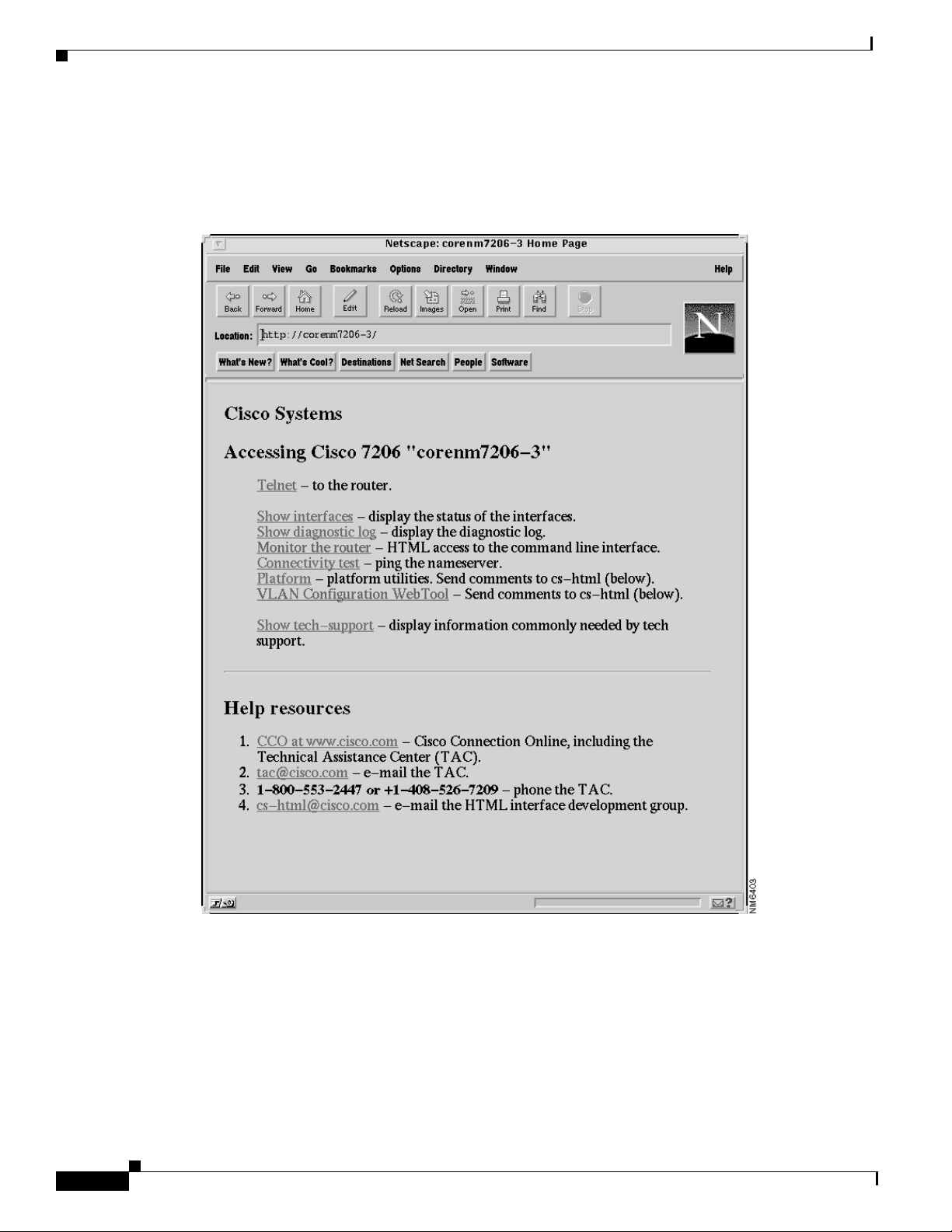
Configuring Bridge Groups Using the 12E/2FE VLAN Configuration WebTool
The 12E/2FE VLAN Configuration WebTool, shown in Figure 2, is a web browser-based Java applet that
displays configured interfaces and bridge groups for PA-12E/2FE port adapters installed in Cisco
routers. With the WebTool you can perform the following tasks:
• Create and delete bridge groups (also referred to as VLANs)
• Add and remove PA-12E/2FE interfaces from bridge groups
• Assign colors to bridge groups and PA-12E/2FE interfaces
• Administratively shut down (disable) and bring up (enable) PA-12E/2FE interfaces
• View the bridge-group status of each PA-12E/2FE interface
Cisco IOS Interface Configuration Guide
IC-31
Page 10
Configuring an Ethernet or Fast Ethernet Interface
You can access the 12E/2FE VLAN Configuration WebTool from your router’s home page. For complete
procedures on how to use the VLAN Configuration WebTool, refer to the PA-12E/2FE Ethernet Switch
Port Adapter book that accompanies the hardware.
Figure 2 Example Home Page for a Cisco 7200 Series Router (Cisco 7206 Shown)
Configuring LAN Interfaces
IC-32
All Cisco routers running Cisco IOS Release 11.0 or later have a home page. All Cisco router home
pages are password protected. Contact your network administrator if you do not have the name or
password for your Cisco 7200 series router.
If your router has an installed PA- 12E/2FE port adapter, the 12E/2FE VLAN Configuration WebTool
shown in Figure 2 can be accessed from the router’s home page using a Java-enabled web browser.
Cisco IOS Interface Configuration Guide
Page 11

Configuring LAN Interfaces
Configuring the 100VG-AnyLAN Port Adapter
The 100VG-AnyLAN port adapter (PA-100VG) is available on Cisco 7200 series routers and on
Cisco 7500 series routers.
The PA-100VG provides a single interface compatible with and specified by IEEE 802.12 to support
100 Mbps over Category 3 or Category 5 unshielded twisted-pair (UTP) cable with RJ-45 terminators.
The PA-100VG supports 802.3 Ethernet packets and can be monitored with the IEEE 802.12 Interface
MIB.
To configure the PA-100VG port adapter, use the following commands beginning in global configuration
mode:
Command Purpose
Step 1
Step 2
Step 3
interface vg-anylan
slot/port-adapter/port
(Cisco 7500)
or
interface vg-anylan slot/port
(Cisco 7200)
ip address ip-address mask
frame-type ethernet
Configuring Fast EtherChannel
Specifies a 100VG-AnyLAN interface and enters interface
configuration.
Specifies the IP address and subnet mask to the interface.
Configures the frame type. Currently, only Ethernet frames are
supported. The frame type defaults to Ethernet.
Note The port number for the 100VG-AnyLAN port adapter is always 0.
Configuring the PA-100VG interface is similar to configuring an Ethernet or Fast Ethernet interface. To
display information about the 100VG-AnyLAN port adapter, use the show interfaces vg-anylan EXEC
command.
Configuring Fast EtherChannel
The Fast EtherChannel feature allows multiple Fast Ethernet point-to-point links to be bundled into one
logical link to provide bidirectional bandwidth of up to 800 Mbps. Fast EtherChannel builds on
standards-based 802.3 full-duplex Fast Ethernet to provide fault-tolerant, high-speed links between
switches, routers, and servers. This feature can be configured between Cisco 7500 series routers and
Cisco 7000 series routers with the 7000 Series Route Switch Processor (RSP7000) and 7000 Series
Chassis Interface (RSP7000CI) or between a Cisco 7500 series router or a Cisco 7000 series router with
the RSP7000 and RSP700CI and a Catalyst 5000 switch.
Note Using the Fast EtherChannel feature on a Catalyst 5000 switch requires a hardware
upgrade. Contact your local sales representative for upgrade details.
Fast EtherChannel provides higher bidirectional bandwidth, redundancy, and load sharing. Up to four
Fast Ethernet interfaces can be bundled in a port-channel, and the router or switch can support up to four
port-channels. The Fast EtherChannel feature is capable of load balancing traffic across the Fast Ethernet
Cisco IOS Interface Configuration Guide
IC-33
Page 12

Configuring Fast EtherChannel
links. Unicast, broadcast, and multicast traffic is distributed across the links providing higher
performance and redundant parallel paths. In the event of a link failure, traffic is redirected to remaining
links within the Fast EtherChannel without user intervention.
In this release of the Fast EtherChannel feature, IP traffic is distributed over the port-channel interface
while traffic from other routing protocols is sent over a single link. Bridged traffic is distributed based
on the Layer 3 information in the packet. If the Layer 3 information does not exist in the packet, the
traffic is sent over the first link.
Fast EtherChannel supports all features currently supported on the Fast Ethernet interface. You must
configure these features on the port-channel interface rather than on the individual Fast Ethernet
interfaces. Fast EtherChannel connections are fully compatible with Cisco IOS virtual LAN (VLAN)
and routing technologies. The Inter-Switch Link (ISL) VLAN trunking protocol can carry multiple
VLANs across a Fast EtherChannel, and routers attached to Fast EtherChannel links can provide full
multiprotocol routing with support for host standby using Host Standby Router Protocol (HSRP).
The port-channel (consisting of up to four Fast Ethernet interfaces) is treated as a single interface.
Port-channel is used in the Cisco IOS software to maintain compatibility with existing commands on the
Catalyst 5000 switch. You create the Fast EtherChannel by using the interface port-channel interface
configuration command. You can assign up to four Fast Ethernet interfaces to a port-channel by using
the channel-group interface configuration command.
Fast EtherChannel also supports the following two features:
Configuring LAN Interfaces
• Support for host standby using Host Standby Router Protocol (HSRP)
For more information about configuring HSRP, refer to the “Configuring IP Services” chapter in the
Cisco IOS IP and IP Routing Configuration Guide.
• Support for Cisco Express Forwarding (CEF) and distributed CEF (dCEF)
For more information about configuring CEF, refer to the “Cisco Express Forwarding” chapter in
the Cisco IOS Switching Services Configuration Guide.
For information on how to configure Ethernet or Fast Ethernet, see the tasks listed in the “Configuring
an Ethernet or Fast Ethernet Interface” section.
Fast EtherChannel Configuration Task List
Perform the tasks in the following sections to configure Fast EtherChannel. To configure Fast
EtherChannel, perform the following required steps:
1. Create a port-channel interface and assign an IP address.
2. Assign the Fast Ethernet interfaces (up to four) to the port-channel interface.
For information on other configuration tasks for the Fast EtherChannel, see the “Configuring an Ethernet
or Fast Ethernet Interface” section.
For information on other commands that can be used by the Fast EtherChannel, refer to the other
configuration guides in the Cisco IOS documentation set.
IC-34
Cisco IOS Interface Configuration Guide
Page 13

Configuring LAN Interfaces
Configuring the Port-Channel Interface
To configure the port-channel interface, use the following commands beginning in global configuration
mode:
Command Purpose
Step 1
Step 2
Step 3
Step 4
Step 5
interface port-channel
channel-number
ip address ip-address mask
mac-address ieee-address
end
show interface port-channel
Creates the port-channel interface and enters interface configuration mode. The
channel number can be 1 to 4.
Assigns an IP address and subnet mask to the Fast EtherChannel.
If you configure ISL, you must assign the IP address to the subinterface (for
example, interface port-channel 1.1—an IP address per VLAN) and you must
specify the encapsulation with VLAN number under that subinterface (for
example, encapsulation isl 100).
(Optional) Assigns a static MAC address to the Fast EtherChannel.
If you do not assign a static MAC address on the port-channel interface, the
Cisco IOS software automatically assigns a MAC address. If you assign a static
MAC address and then later remove it, the Cisco IOS software automatically
assigns a MAC address.
(Optional) Enables other supported interface commands to execute, and exits
when they have finished.
Displays information about the port-channel interface so you can verify the
configuration.
Configuring Fast EtherChannel
Note If you want to use the Cisco Discovery Protocol (CDP), you must configure it on the
physical Ethernet, Fast Ethernet, or GigabitEthernet interface, not on the port-channel
interface.
Caution With Release 11.1(20)CC and later, Fast EtherChannel supports CEF/dCEF. We
recommend that you clear all explicit ip route-cache distributed commands from the Fast
Ethernet interfaces before enabling dCEF on the port-channel interface. Doing this gives
the port-channel interface proper control of its physical Fast Ethernet links. When you
enable CEF/dCEF globally, all interfaces that support CEF/dCEF are enabled. When
CEF/dCEF is enabled on the port-channel interface, it is automatically enabled on each of
the Fast Ethernet interfaces in the channel group. However, if you have previously disabled
CEF/dCEF on the Fast Ethernet interface, CEF/dCEF is not automatically enabled. In this
case, you must enable CEF/dCEF on the Fast Ethernet interface.
Cisco IOS Interface Configuration Guide
IC-35
Page 14

Configuring Fast EtherChannel
Configuring the Fast Ethernet Interfaces
To assign the Fast Ethernet interfaces to the Fast EtherChannel, use the following commands beginning
in global configuration mode:
Command Purpose
Step 1
Step 2
Step 3
Step 4
Step 5
Step 6
interface fastethernet
slot/port-adapter/port
no ip address
channel-group channel-number
exit
end
show interface port-channel
Creates or modifies an existing Fast Ethernet interface and enters interface
configuration mode.
Disables the IP address before performing the next step, if the Fast Ethernet
interface already exists and has an IP address assigned.
Assigns the Fast Ethernet interfaces to the Fast EtherChannel. The channel
number is the same as the channel number you specified when you created the
port-channel interface.
Exits interface configuration mode. Repeat Steps 1 through 4 to add up to four
Fast Ethernet interfaces to the Fast EtherChannel.
(Optional) Enables other supported interface commands to execute, and exits
when they have finished.
Displays information about the Fast Ethernet interface so you can verify the
configuration.
Configuring LAN Interfaces
Step 1
Step 2
Step 3
Caution The port-channel interface is the routed interface. Do not enable Layer 3 addresses on the
physical Fast Ethernet interfaces. Do not assign bridge groups on the physical Fast Ethernet
interfaces because it creates loops. Also, you must disable spanning tree.
To remove a Fast Ethernet interface from a Fast EtherChannel, use the following commands beginning
in global configuration mode:
Command Purpose
interface fastethernet
slot/port-adapter/port
no channel-group
end
Specifies the Fast Ethernet interface and enters interface configuration mode.
Removes the Fast Ethernet interface from the channel group.
(Optional) Enables other supported interface commands to execute, and exits
when they have finished.
The Cisco IOS software automatically removes a Fast Ethernet interface from the Fast EtherChannel if
the interface goes down, and the software automatically adds the Fast Ethernet interface to the Fast
EtherChannel when the interface is back up.
Currently, Fast EtherChannel relies on keepalives to detect whether the line protocol is up or down.
Keepalives are enabled by default on the Fast Ethernet interfaces. If the line protocol on the interface
goes down because it did not receive a keepalive signal, the Fast EtherChannel detects that the line
protocol is down and removes the interface from the Fast EtherChannel. However, if the line protocol
remains up because keepalives are disabled on the Fast Ethernet interface, the Fast EtherChannel cannot
detect this link failure (other than a cable disconnect) and does not remove the interface from the Fast
IC-36
Cisco IOS Interface Configuration Guide
Page 15

Configuring LAN Interfaces
Configuring a Fiber Distributed Data Interface
EtherChannel even if the line protocol goes down. This can result in unpredictable behavior. The
implementation of the Port Aggregation Protocol in a subsequent release of this feature will remove the
dependency on keepalives.
See the “LAN Interface Configuration Examples” section for configuration examples.
You can monitor the status of the Fast EtherChannel interface by using the show interfaces
port-channel EXEC command.
Configuring a Fiber Distributed Data Interface
The Fiber Distributed Data Interface (FDDI) is an ANSI-defined standard for timed 100-Mbps token
passing over fiber-optic cable. FDDI is not supported on access servers.
An FDDI network consists of two counter-rotating, token-passing fiber-optic rings. On most networks,
the primary ring is used for data communication and the secondary ring is used as a hot standby. The
FDDI standard sets a total fiber length of 200 kilometers. (The maximum circumference of the FDDI
network is only half the specified kilometers because of the wrapping or looping back of the signal that
occurs during fault isolation.)
The FDDI standard allows a maximum of 500 stations with a maximum distance between active stations
of two kilometers when interconnecting them with multimode fiber or ten kilometers when
interconnected via single mode fiber, both of which are supported by our FDDI interface controllers. The
FDDI frame can contain a minimum of 17 bytes and a maximum of 4500 bytes. Our implementation of
FDDI supports Station Management (SMT) Version 7.3 of the X3T9.5 FDDI specification, offering a
single MAC dual-attach interface that supports the fault-recovery methods of the dual attachment
stations (DASs). The mid-range platforms also support single attachment stations (SASs).
Refer to the Cisco Product Catalog for specific information on platform and interface compatibility. For
installation and configuration information, refer to the installation and configuration publication for the
appropriate interface card or port adapter.
Source-Route Bridging over FDDI on Cisco 4000-M, Cisco 4500-M, and Cisco 4700-M Routers
Source-route bridging (SRB) is supported on the FDDI interface to the Cisco 4000-M, Cisco 4500-M,
and Cisco 4700-M routers. For instructions on configuring autonomous FDDI SRB or fast-switching
SRB over FDDI, refer to the “Configuring Source-Route Bridging” chapter of the Cisco IOS Bridging
and IBM Networking Configuration Guide.
Particle-Based Switching of Source-Route Bridge Packets on Cisco 7200 Series Routers
Source-route bridging (SRB) is supported over Fiber Distributed Data Interface (FDDI).
Particle-based switching is supported for SRB packets (over FDDI and Token Ring) by default.
Particle-based switching adds scatter-gather capability to SRB to improve performance. Particles
represent a communications data packet as a collection of noncontiguous buffers. The traditional
Cisco IOS packet has a packet type control structure and a single contiguous data buffer. A particle
packet has the same packet type control structure, but also maintains a queue of particle type structures,
each of which manages its own block.
Cisco IOS Interface Configuration Guide
IC-37
Page 16

Configuring a Fiber Distributed Data Interface
The scatter-gather architecture used by particle-based switching provides the following advantages:
• Allows drivers to use memory more efficiently (especially when using media that has a large
maximum transmission unit [MTU]). For example, Token Ring buffers could be 512 bytes rather
than 16 KB.
• Allows concurrent use of the same region of memory. For example, on IP multicast a single packet
is received and sent out on multiple interfaces simultaneously.
• Allows insertion or deletion of memory at any location in a packet (not just at the beginning or end).
For information about configuring SRB over FDDI, refer to the “Configuring Source-Route Bridging”
chapter of the Cisco IOS Bridging and IBM Networking Configuration Guide.
Using Connection Management Information
Connection management (CMT) is an FDDI process that handles the transition of the ring through its
various states (off, on, active, connect, and so on) as defined by the X3T9.5 specification. The FIP
provides CMT functions in microcode.
A partial sample output of the show interfaces fddi command follows, along with an explanation of how
to interpret the CMT information in the output.
Phy-A state is active, neighbor is B, cmt signal bits 08/20C, status ALS
Phy-B state is active, neighbor is A, cmt signal bits 20C/08, status ILS
CFM is thru A, token rotation 5000 usec, ring operational 0:01:42
Upstream neighbor 0800.2008.C52E, downstream neighbor 0800.2008.C52E
Configuring LAN Interfaces
The show interfaces fddi example shows that Physical A (Phy-A) completed CMT with its neighbor.
The state is active and the display indicates a Physical B-type neighbor.
The sample output indicates CMT signal bits 08/20C for Phy-A. The transmit signal bits are 08. Looking
at the PCM state machine, 08 indicates that the port type is A, the port compatibility is set, and the LCT
duration requested is short. The receive signal bits are 20C, which indicate the neighbor type is B, port
compatibility is set, there is a MAC on the port output, and so on.
The neighbor is determined from the received signal bits, as follows:
Bit Positions 9876543210
Value Received 1 0 0 0 0 0 1 1 0 0
Interpreting the bits in the diagram above, the received value equals 0x20C. Bit positions 1 and 2 (0 1)
indicate a Physical B-type connection.
The transition states displayed indicate that the CMT process is running and actively trying to establish
a connection to the remote physical connection. The CMT process requires state transition with different
signals being transmitted and received before moving on to the state ahead as indicated in the PCM state
machine. The ten bits of CMT information are transmitted and received in the Signal State. The NEXT
state is used to separate the signaling performed in the Signal State. Therefore, in the preceding sample
output, the NEXT state was entered 11 times.
Note The display line showing transition states is not generated if the FDDI interface has been
shut down, or if the cmt disconnect command has been issued, or if the fddi if-cmt
command has been issued. (The fddi if-cmt command applies to the Cisco 7500 series
routers only.)
IC-38
Cisco IOS Interface Configuration Guide
Page 17

Configuring LAN Interfaces
The CFM state is through A in the sample output, which means this interface’s Phy-A has successfully
completed CMT with the Phy-B of the neighbor and Phy-B of this interface has successfully completed
CMT with the Phy-A of the neighbor.
The display (or nondisplay) of the upstream and downstream neighbor does not affect the ability to route
data. Since the upstream neighbor is also its downstream neighbor in the sample, there are only two
stations in the ring: the network server and the router at address 0800.2008.C52E.
FDDI Configuration Task List
Perform the tasks in the following sections to configure an FDDI interface:
• Specifying a FDDI (Required)
• Enabling FDDI Bridging Encapsulation (Optional)
• Enabling Full-Duplex Mode on the FDDI (Optional)
• Setting the Token Rotation Time (Optional)
• Setting the Transmission Valid Timer (Optional)
• Controlling the Transmission Timer (Optional)
Configuring a Fiber Distributed Data Interface
• Modifying the C-Min Timer (Optional)
• Modifying the TB-Min Timer (Optional)
• Modifying the FDDI Timeout Timer (Optional)
• Controlling SMT Frame Processing (Optional)
• Enabling Duplicate Address Checking (Optional)
• Setting the Bit Control (Optional)
• Controlling the CMT Microcode (Optional)
• Starting and Stopping FDDI (Optional)
• Setting FDDI Frames Per Token Limit (Optional)
• Controlling the FDDI SMT Message Queue Size (Optional)
• Preallocating Buffers for Bursty FDDI Traffic (Optional)
Specifying a FDDI
To specify an FDDI interface and enter interface configuration mode, use one of the following
commands in global configuration mode:
Command Purpose
interface fddi number
interface fddi slot/port
Begins interface configuration.
Begins interface configuration for the Cisco 7200 or Cisco 7500 series routers.
Cisco IOS Interface Configuration Guide
IC-39
Page 18

Configuring a Fiber Distributed Data Interface
Enabling FDDI Bridging Encapsulation
Cisco FDDI by default uses the SNAP encapsulation format defined in RFC 1042. It is not necessary to
define an encapsulation method for this interface when using the FIP.
FIP fully supports transparent and translational bridging for the following configurations:
• FDDI-to-FDDI
• FDDI-to-Ethernet
• FDDI-to-Token Ring
Enabling FDDI bridging encapsulation places the FIP into encapsulation mode when doing bridging. In
transparent mode, the FIP interoperates with earlier versions of encapsulating interfaces when
performing bridging functions on the same ring. When using the FIP, you can specify the encapsulation
method by using the following command in interface configuration mode:
Command Purpose
fddi encapsulate
Specifies the encapsulation method for the FIP.
Configuring LAN Interfaces
When you are doing translational bridging, use routing for routable protocols and use translational
bridging for the rest (such as LAT).
Note Bridging between dissimilar media presents several problems that can prevent
communications. These problems include bit-order translation (using MAC addresses as
data), maximum transfer unit (MTU) differences, frame status differences, and multicast
address usage. Some or all of these problems might be present in a multimedia-bridged
LAN and might prevent communication. These problems are most prevalent in networks
that bridge between Token Rings and Ethernet networks or between Token Rings and FDDI
because of the different ways Token Ring is implemented by the end nodes.
We are currently aware of problems with the following protocols when bridged between Token Ring and
other media: AppleTalk, DECnet, IP, Novell IPX, Phase IV, VINES, and XNS. Further, the following
protocols might have problems when bridged between FDDI and other media: Novell IPX and XNS. We
recommend that these protocols be routed whenever possible.
Enabling Full-Duplex Mode on the FDDI
To enable full-duplex mode on the PA-F/FD-SM and PA-F/FD-MM port adapters, use one of the
following commands in interface configuration mode:
Command Purpose
full-duplex
or
no half-duplex
Enables full-duplex on the FDDI interface of the PA-F/FD-SM and
PA-F/FD-MM port adapter.
IC-40
Cisco IOS Interface Configuration Guide
Page 19

Configuring LAN Interfaces
Setting the Token Rotation Time
You can set the FDDI token rotation time to control ring scheduling during normal operation and to
detect and recover from serious ring error situations. To do so, use the following command in interface
configuration mode:
Command Purpose
fddi token-rotation-time microseconds
The FDDI standard restricts the allowed time to be greater than 4000 microseconds and less than
165,000 microseconds. As defined in the X3T9.5 specification, the value remaining in the token rotation
timer (TRT) is loaded into the token holding timer (THT). Combining the values of these two timers
provides the means to determine the amount of bandwidth available for subsequent transmissions.
Sets the FDDI token rotation time.
Setting the Transmission Valid Timer
You can set the transmission timer to recover from a transient ring error by using the following command
in interface configuration mode:
Configuring a Fiber Distributed Data Interface
Command Purpose
fddi valid-transmission-time microseconds
Sets the FDDI valid transmission timer.
Controlling the Transmission Timer
You can set the FDDI control transmission timer to control the FDDI TL-Min time, which is the
minimum time to transmit a Physical Sublayer or PHY line state before advancing to the next Physical
Connection Management or PCM state as defined by the X3T9.5 specification. To do so, use the
following command in interface configuration mode:
Command Purpose
fddi tl-min-time microseconds
Sets the FDDI control transmission timer.
Modifying the C-Min Timer
You can modify the C-Min timer on the PCM from its default value of 1600 microseconds by using the
following command in interface configuration mode:
Command Purpose
fddi c-min microseconds
Sets the C-Min timer on the PCM.
Cisco IOS Interface Configuration Guide
IC-41
Page 20

Configuring a Fiber Distributed Data Interface
Modifying the TB-Min Timer
You can change the TB-Min timer in the PCM from its default value of 100 ms. To do so, use the
following command in interface configuration mode:
Command Purpose
fddi tb-min milliseconds
Sets TB-Min timer in the PCM.
Modifying the FDDI Timeout Timer
You can change the FDDI timeout timer in the PCM from its default value of 100 ms. To do so, use the
following command in interface configuration mode:
Command Purpose
fddi t-out milliseconds
Sets the timeout timer in the PCM.
Configuring LAN Interfaces
Controlling SMT Frame Processing
You can disable and enable SMT frame processing for diagnostic purposes. To do so, use one of the
following commands in interface configuration mode:
Command Purpose
no fddi smt-frames
fddi smt-frames
Disables SMT frame processing.
Enables SMT frame processing.
Enabling Duplicate Address Checking
You can enable the duplicate address detection capability on the FDDI. If the FDDI finds a duplicate
address, it displays an error message and shuts down the interface. To enable duplicate address checking,
use the following command in interface configuration mode:
Command Purpose
fddi duplicate-address-check
Enables duplicate address checking capability.
Setting the Bit Control
You can set the FDDI bit control to control the information transmitted during the Connection
Management (CMT) signaling phase. To do so, use the following command in interface configuration
mode:
Command Purpose
fddi cmt-signal-bits signal-bits [phy-a | phy-b]
Cisco IOS Interface Configuration Guide
IC-42
Sets the FDDI bit control.
Page 21

Configuring LAN Interfaces
Controlling the CMT Microcode
You can control whether the CMT onboard functions are on or off. The FIP provides CMT functions in
microcode. These functions are separate from those provided on the processor card and are accessed
through EXEC commands.
The default is for the FIP CMT functions to be on. A typical reason to disable is when you work with
new FDDI equipment and have problems bringing up the ring. If you disable the CMT microcode, the
following actions occur:
• The FIP CMT microcode is disabled.
• The main system code performs the CMT function while debugging output is generated.
To disable the CMT microcode, use the following command in interface configuration mode:
Command Purpose
no fddi if-cmt
Disables the FCIT CMT functions.
Starting and Stopping FDDI
Configuring a Fiber Distributed Data Interface
In normal operation, the FDDI interface is operational once the interface is connected and configured.
You can start and stop the processes that perform the CMT function and allow the ring on one fiber to
be stopped. To do so, use either of the following commands in EXEC mode:
Command Purpose
cmt connect [interface-name [phy-a | phy-b]]
cmt disconnect [interface-name [phy-a | phy-b]]
Starts CMT processes on FDDI ring.
Stops CMT processes on FDDI ring.
Do not use either of the preceding commands during normal operation of FDDI; they are used during
interoperability tests.
Setting FDDI Frames Per Token Limit
The FDDI interface is able to transmit multiple frames per token on a Cisco 4000, Cisco 4500, and a
Cisco 4700 series routers, instead of only a single frame at a time. You can specify the maximum number
of frames to be transmitted with each token capture. This significantly improves your throughput, when
you have heavy or very bursty traffic.
To configure the FDDI interface to transmit a maximum number of frames per token capture, use the
following commands:
Command Purpose
Step 1
Step 2
Step 3
Step 4
Step 5
configure terminal
interface fddi0
fddi ?
fddi frames-per-token ?
fddi frames-per-token number
Enters global configuration mode.
Enters interface configuration mode.
Shows fddi command options.
Shows fddi frames-per-token command options.
Specifies the maximum number of frames to be transmitted per
token capture.
Cisco IOS Interface Configuration Guide
IC-43
Page 22

Configuring a Hub Interface
Controlling the FDDI SMT Message Queue Size
You can set the maximum number of unprocessed FDDI Station Management (SMT) frames that will be
held for processing. Setting this number is useful if the router you are configuring gets bursts of
messages arriving faster than the router can process them. To set the number of frames, use the following
command in global configuration mode:
Command Purpose
smt-queue-threshold number
Sets SMT message queue size.
Preallocating Buffers for Bursty FDDI Traffic
The FCI card preallocates three buffers to handle bursty FDDI traffic (for example, NFS bursty traffic).
You can change the number of preallocated buffers by using the following command in interface
configuration mode:
Command Purpose
fddi burst-count
Preallocates buffers to handle bursty FDDI traffic.
Configuring LAN Interfaces
Configuring a Hub Interface
The Cisco 2500 series routers includes routers that have hub functionality for an Ethernet interface. The
hub is a multiport repeater. The advantage of an Ethernet interface over a hub is that the hub provides a
star-wiring physical network configuration while the Ethernet interface provides 10BASE-T physical
network configuration. The router models with hub ports and their configurations are as follows:
• Cisco 2505—1 Ethernet (8 ports) and 2 serial
• Cisco 2507—1 Ethernet (16 ports) and 2 serial
• Cisco 2516—1 Ethernet (14 ports), 2 serial, and 1 ISDN BRI
We provide SNMP management of the Ethernet hub as specified in RFC 1516, “Definitions of Managed
Objects for IEEE 802.3 Repeater Devices.”
To configure hub functionality on an Ethernet interface, perform the tasks in the following sections:
• Enabling a Hub Port (Required)
• Disabling or Enabling Automatic Receiver Polarity Reversal (Optional)
• Disabling or Enabling the Link Test Function (Optional)
• Enabling Source Address Control (Optional)
• Enabling SNMP Illegal Address Trap (Optional)
For configuration examples, see the “Hub Configuration Examples” section.
IC-44
Cisco IOS Interface Configuration Guide
Page 23

Configuring LAN Interfaces
Enabling a Hub Port
To enable a hub port, use the following commands in global configuration mode:
Command Purpose
Step 1
Step 2
hub ethernet number port [end-port]
no shutdown
Specifies the hub number and the hub port (or range of hub ports) and
enters hub configuration mode.
Enables the hub ports.
Disabling or Enabling Automatic Receiver Polarity Reversal
On Ethernet hub ports only, the hub ports can invert, or correct, the polarity of the received data if the
port detects that the received data packet waveform polarity is reversed due to a wiring error. This receive
circuitry polarity correction allows the hub to repeat subsequent packets with correct polarity. When
enabled, this function is executed once after reset of a link fail state.
Automatic receiver polarity reversal is enabled by default. To disable this feature on a per-port basis, use
the following command in hub configuration mode:
Configuring a Hub Interface
Command Purpose
no auto-polarity
To enable automatic receiver polarity reversal on a per-port basis, use the following command in hub
configuration mode:
Command Purpose
auto-polarity
Disables automatic receiver polarity reversal.
Enables automatic receiver polarity reversal.
Disabling or Enabling the Link Test Function
The link test function applies to Ethernet hub ports only. The Ethernet ports implement the link test
function as specified in the 802.3 10BASE-T standard. The hub ports will transmit link test pulses to any
attached twisted pair device if the port has been inactive for more than 8 to 17 ms.
If a hub port does not receive any data packets or link test pulses for more than 65 to 132 ms and the link
test function is enabled for that port, that port enters link fail state and cannot transmit or receive. The
hub port is enabled again when it receives four consecutive link test pulses or a data packet.
The link test function is enabled by default. To allow the hub to interoperate with 10BASE-T twisted-pair
networks that do not implement the link test function, the hub’s link test receive function can be disabled
on a per-port basis. To do so, use the following command in hub configuration mode:
Command Purpose
no link-test
Disables the link test function.
Cisco IOS Interface Configuration Guide
IC-45
Page 24

Configuring a Hub Interface
To enable the link test function on a hub port connected to an Ethernet interface, use the following
command in hub configuration mode:
Command Purpose
link-test
Enables the link test function.
Enabling Source Address Control
On an Ethernet hub port only, you can configure a security measure such that the port accepts packets
only from a specific MAC address. For example, suppose your workstation is connected to port 3 on a
hub, and source address control is enabled on port 3. Your workstation has access to the network because
the hub accepts any packet from port 3 with your workstation’s MAC address. Any packets arriving with
a different MAC address cause the port to be disabled. The port is enabled again after 1 minute and the
MAC address of incoming packets is checked again.
To enable source address control on a per-port basis, use the following command in hub configuration
mode:
Configuring LAN Interfaces
Command Purpose
source-address [mac-address]
If you omit the optional MAC address, the hub remembers the first MAC address it receives on the
selected port, and allows only packets from the learned MAC address.
See the examples of establishing source address control in the “Hub Configuration Examples” section.
Enables source address control.
Enabling SNMP Illegal Address Trap
To enable the router to issue an SNMP trap when an illegal MAC address is detected on an Ethernet hub
port, use the following commands in hub configuration mode:
Command Purpose
Step 1
Step 2
hub ethernet number port [end-port]
snmp trap illegal-address
You may need to set up a host receiver for this trap type (snmp-server host) for a Network Management
System (NMS) to receive this trap type. The default is no trap. For an example of configuring a SNMP
trap for an Ethernet hub port, see the “Hub Configuration Examples” section.
Specifies the hub number and the hub port (or range of hub ports) and
enters hub configuration mode.
Enables the router to issue an SNMP trap when an illegal MAC address
is detected on the hub port.
IC-46
Cisco IOS Interface Configuration Guide
Page 25

Configuring LAN Interfaces
Configuring a LAN Extender Interface
The Cisco 1001 and Cisco 1002 LAN Extenders are two-port chassis that connect a remote Ethernet
LAN to a core router at a central site (see Figure 3). The LAN Extender is intended for small networks
at remote sites. Overview information for LAN extender interfaces is provided in these sections:
• Connecting a LAN Extender to a Core Router
• Installing a LAN Extender at a Remote Site
• Discovering the MAC Address
• Upgrading Software for the LAN Extender
• Configuring the LAN Extender
For examples of LAN Extender interface configuration tasks, see the “LAN Extender Interface
Configuration Task List” section.
Connecting a LAN Extender to a Core Router
Configuring a LAN Extender Interface
The remote site can have one Ethernet network. The core router can be a Cisco 2500 series, Cisco 4000
series, Cisco 4500 series, Cisco 4700 series, Cisco 7500 series, or AGS+ router running Cisco IOS
Release 10.2(2) and later, which support the LAN Extender host software.
Figure 3 shows the connection between the LAN Extender and the core router via a short leased serial
line, typically a 56-kbps or 64-kbps line. However, the connection can also be via T1 or E1 lines.
Figure 3 Cisco 1000 Series LAN Extender Connection to a Core Router
S0
Other
networks
Core router
Expanded View of the Connection to a Core Router
Figure 4 is an expanded view of Figure 3 that shows all the components of the LAN Extender connection
to a core router. On the left is the core router, which is connected to the LAN Extender as well as to other
networks. In the core router, you configure a LAN Extender interface, which is a logical interface that
connects the core router to the LAN Extender chassis. In the core router, you also configure a serial
interface, which is the physical interface that connects the core router to the LAN Extender. You then
bind, or associate, the LAN Extender interface to the physical serial interface.
Remote
LAN
LAN Extender
S2921
Figure 4 shows the actual physical connection between the core router and the LAN Extender. The serial
interface on the core router is connected by a leased serial line to a serial port on the LAN Extender. This
creates a virtual Ethernet connection, which is analogous to having inserted an Ethernet interface
processor into the core router.
Cisco IOS Interface Configuration Guide
IC-47
Page 26

Configuring a LAN Extender Interface
Figure 4 Expanded View of Cisco 1000 Series LAN Extender Connection
Configuring LAN Interfaces
Other
networks
Core Router
LEX Serial
A
Virtual Ethernet connection
Management of the LAN Extender Interface
Although there is a physical connection between the core router and the LAN Extender, what you
actually manage is a remote Ethernet LAN. Figure 5 shows the connection you are managing, which is
a LAN Extender interface connected to an Ethernet network. The virtual Ethernet connection (the serial
interface and LAN Extender) has been removed from the figure, and points A and B, which in Figure 4
were separated by the virtual Ethernet connection, are now adjacent. All LAN Extender interface
configuration tasks described in this chapter apply to the interface configuration shown in Figure 5.
Figure 5 LAN Extender Interface Connected to an Ethernet Network
Other
networks
Core Router
LEX Ethernet
LAN Extender
AB
B
Remote
LAN
Ethernet
S2979
Remote
LAN
S2980
Installing a LAN Extender at a Remote Site
To install a LAN Extender at a remote site, refer to the Cisco 1000 Series Hardware Installation
publication.
Discovering the MAC Address
After the LAN Extender has been installed at the remote site, you need to obtain its MAC address. Each
LAN Extender is preconfigured with a permanent (burned-in) MAC address. The address is assigned at
the factory; you cannot change it. The MAC address is printed on the LAN Extender’s packing box. (If
necessary, you can also display the MAC address with the debug ppp negotiation command.) The first
three octets of the MAC address (the vendor code) are always the hexadecimal digits 00.00.0C.
Upgrading Software for the LAN Extender
You can upgrade software for the LAN Extender on the host router with a TFTP server that is local to
the host router.
The LAN Extender and core router communicate using the Point-to-Point Protocol (PPP). Before you
can configure the LAN Extender from the core router, you must first enable PPP encapsulation on the
serial interface to which the LAN Extender is connected.
IC-48
Cisco IOS Interface Configuration Guide
Page 27

Configuring LAN Interfaces
Configuring the LAN Extender
You configure the LAN Extender from the core router—either a Cisco 4000 series or Cisco 7000 series
router—as if it were simply a network interface board. The LAN Extender cannot be managed or
configured from the remote Ethernet LAN or via a Telnet session.
To configure the LAN Extender, you configure a logical LAN Extender interface on the core router and
assign the MAC address from your LAN Extender to that interface. Subsequently, during the PPP
negotiation on the serial line, the LAN Extender sends its preconfigured MAC address to the core router.
The core router then searches for an available (preconfigured) LAN Extender interface, seeking one to
which you have already assigned that MAC address. If the core router finds a match, it binds, or
associates, that LAN Extender interface to the serial line on which that MAC address was negotiated. At
this point, the LAN Extender interface is created and is operational. If the MAC address does not match
one that is configured, the connection request is rejected. Figure 6 illustrates this binding process.
Figure 6 Binding a Serial Line to a LAN Extender Interface
S1
Configuring a LAN Extender Interface
Serial
Interface
S0
S1
S2
1.)
2.)
3.)
4.)
S0
Core router
Extender Interfaces
S1
S0 S2
Core router
00.00.0c.01.00.05
corresponds to
LAN Extender
interface 2 on
serial interface 2
S1
S0 S2
Core router
LAN Extender interface 2,
and hence LAN extender
is bound to serial
interface 2
S2
Available LAN
0
1
2
00.00.0c.00.00.01
00.00.0c.00.01.03
00.00.0c.01.00.05
My MAC address
00.00.0c.01.00.05
LAN Extender
MAC Address
00.00.0c.01.00.05
MAC
Address
PPP
negotiation
LAN Extender
S2922
LAN Extender
Cisco IOS Interface Configuration Guide
IC-49
Page 28

Configuring a LAN Extender Interface
LAN Extender Interface Configuration Task List
To configure a LAN Extender interface, perform the tasks described in the following sections:
• Configuring and Creating a LAN Extender Interface (Required)
• Defining Packet Filters (Optional)
• Controlling Priority Queueing (Optional)
• Controlling the Sending of Commands to the LAN Extender (Optional)
• Shutting Down and Restarting the LAN Extender’s Ethernet Interface (Optional)
• Restarting the LAN Extender (Optional)
• Downloading a Software Image to the LAN Extender (Optional)
• Troubleshooting the LAN Extender (Optional)
To monitor the LAN Extender interface, see the “Monitoring and Maintaining the Interface” section in
the “Interface Configuration Overview” chapter. For configuration examples, see the “LAN Extender
Enablement Interface Example” and the “LAN Extender Interface Access List Examples” sections.
Configuring LAN Interfaces
Configuring and Creating a LAN Extender Interface
To configure and create a LAN Extender interface, you configure the LAN Extender interface itself and
the serial interface to which the LAN Extender is physically connected. The order in which you
configure these two interface interfaces does not matter. However, you must first configure both
interfaces in order for the LAN Extender interface to bind (associate) to the serial interface.
To create and configure a LAN Extender interface, use the following commands starting in interface
configuration mode:
Command Purpose
Step 1
Step 2
Step 3
Step 4
Step 5
Step 6
Step 7
Step 8
interface lex number
interface lex slot/port
lex burned-in-address ieee-address
ip address ip-address mask
exit
interface serial number
encapsulation ppp
Ctrl-Z
copy system:running-config
nvram:startup-config
Configures a LAN Extender interface in global configuration mode and
enters interface configuration mode.
or
Configures a LAN Extender on a Cisco 7000 series routers.
Assigns the burned-in MAC address from your LAN Extender to the
LAN Extender interface.
Assigns a protocol address to the LAN Extender interface.
Returns to global configuration mode.
Configures a serial interface in global configuration mode and enters
interface configuration mode.
Enables PPP encapsulation on the serial interface in interface
configuration mode.
Exits interface configuration mode.
Saves the configuration to memory.
IC-50
Note that there is no correlation between the number of the serial interface and the number of the LAN
Extender interface. These interfaces can have the same or different numbers.
Cisco IOS Interface Configuration Guide
Page 29

Configuring LAN Interfaces
Note Do not configure the MTU to a value other than the default value when you are configuring
a LAN Extender interface.
Defining Packet Filters
You can configure specific administrative filters that filter frames based on their source MAC address.
The LAN Extender forwards packets between a remote LAN and a core router. It examines frames and
transmits them through the internetwork according to the destination address, and it does not forward a
frame back to its originating network segment.
You define filters on the LAN Extender interface in order to control which packets from the remote
Ethernet LAN are permitted to pass to the core router (see Figure 7). These filters are applied only on
traffic passing from the remote LAN to the core router. Filtering on the LAN Extender interface is
actually performed in the LAN Extender, not on the core router. This means that the filtering is done
using the LAN Extender CPU, thus offloading the function from the core router. This process also saves
bandwidth on the WAN, because only the desired packets are forwarded from the LAN Extender to the
core router. Whenever possible, you should perform packet filtering on the LAN Extender.
Configuring a LAN Extender Interface
Figure 7 Packet Filtering on the LAN Extender
Other
networks
Core router
Packet flow
LAN Extender
Ethernet
Packet filters
Filters applied by lex
input-address-list and lex
input-type-list commands
Remote
LAN
S2981
You can also define filters on the core router to control which packets from the LAN Extender interface
are permitted to pass to other interfaces on the core router (see Figure 8). You do this using the standard
filters available on the router. This means that all packets are sent across the WAN before being filtered
and that the filtering is done using the core router’s CPU.
Figure 8 Packet Filtering on the Core Router
Filters applied by standard
router input filters
LEX Input packet filters
Packet flow
Packet flow
Core router
LEX Output packet filters
LAN Extender
Filters applied by standard
router output filters
S2982
Cisco IOS Interface Configuration Guide
IC-51
Page 30

Configuring a LAN Extender Interface
The major reason to create access lists on a LAN Extender interface is to prevent traffic that is local to
the remote Ethernet LAN from traversing the WAN and reaching the core router. You can filter packets
by MAC address, including vendor code, and by Ethernet type code. To define filters on the LAN
Extender interface, perform the tasks described in one or both of the following sections:
• Filtering by MAC Address and Vendor Code
• Filtering by Protocol Type
Note When setting up administrative filtering, remember that there is virtually no performance
penalty when filtering by vendor code, but there can be a performance penalty when
filtering by protocol type.
When defining access lists, keep the following points in mind:
• You can assign only one vendor code access list and only one protocol type access list to an
interface.
• The conditions in the access list are applied to all outgoing packets from the LAN Extender.
• The entries in an access list are scanned in the order you enter them. The first entry that matches the
outgoing packet is used.
Configuring LAN Interfaces
• An implicit “deny everything” entry is automatically defined at the end of an access list unless you
include an explicit “permit everything” entry at the end of the list. This means that unless you have
an entry at the end of an access list that explicitly permits all packets that do no match any of the
other conditions in the access list, these packets will not be forwarded out the interface.
• All new entries to an existing list are placed at the end of the list. You cannot add an entry to the
middle of a list.
• If you do not define any access lists on an interface, it is as if you had defined an access lists with
only a “permit all” entry. All traffic passes across the interface.
Filtering by MAC Address and Vendor Code
You can create access lists to administratively filter MAC addresses. These access lists can filter groups
of MAC addresses, including those with particular vendor codes. There is no noticeable performance
loss in using these access lists, and the lists can be of indefinite length.
You can filter groups of MAC addresses with particular vendor codes by creating a vendor code access
list and then by applying an access list to an interface.
To create a vendor code access list, use the following command in global configuration mode:
Command Purpose
access-list access-list-number
{permit | deny} address mask
Creates an access list to filter frames by canonical (Ethernet-ordered) MAC
address.
IC-52
Note Token Ring and FDDI networks swap their MAC address bit ordering, but Ethernet
networks do not. Therefore, an access list that works for one medium might not work for
others.
Cisco IOS Interface Configuration Guide
Page 31

Configuring LAN Interfaces
Once you have defined an access list to filter by a particular vendor code, you can assign this list to a
particular LAN Extender interface so that the interface will then filter based on the MAC source
addresses of packets received on that LAN Extender interface. To apply the access list to an interface,
use the following command in interface configuration mode:
Command Purpose
lex input-address-list
access-list-number
Assigns an access list to an interface for filtering by MAC source addresses.
For an example of creating an access list and applying it to a LAN Extender interface, see the “LAN
Extender Interface Access List Examples” section.
Filtering by Protocol Type
You can filter by creating a type-code access list and applying it to a LAN Extender interface.
The LAN Extender interface can filter only on bytes 13 and 14 of the Ethernet frame. In Ethernet packets,
these two bytes are the type field. For a list of Ethernet type codes, refer to the “Ethernet Type Codes”
appendix in the Cisco IOS Bridging and IBM Networking Command Reference, Volume I. In 802.3
packets, these two bytes are the length field.
You can filter by protocol type by creating a protocol-type access list and then applying the access list
to an interface.
Configuring a LAN Extender Interface
Note Type-code access lists can have an impact on system performance; therefore, keep the lists
as short as possible and use wildcard bit masks whenever possible.
To create a protocol-type access list, use the following command in global configuration mode:
Command Purpose
access-list access-list-number
{permit | deny} type-code wild-mask
Creates an access list to filter frames by protocol type.
To apply an access list to an interface, use the following command in interface configuration mode:
Command Purpose
lex input-type-list access-list-number
Adds a filter for Ethernet- and SNAP-encapsulated packets on input.
For an example of creating an access list and applying it to a LAN Extender interface, see the “LAN
Extender Interface Access List Examples” section.
Controlling Priority Queueing
Priority output queueing is an optimization mechanism that allows you to set priorities on the type of
traffic passing through the network. Packets are classified according to various criteria, including
protocol and subprotocol type. Packets are then queued on one of four output queues.
Cisco IOS Interface Configuration Guide
IC-53
Page 32

Configuring a LAN Extender Interface
To control priority queueing on a LAN Extender interface, perform the following tasks:
• Set the priority by protocol type.
• Assign a priority group to an interface.
To establish queueing priorities based on the protocol type, use one of the following commands in global
configuration mode:
Command Purpose
priority-list list protocol protocol
{high | medium | normal | low}
Establishes queueing priorities based on the protocol type.
or
priority-list list protocol bridge {high
| medium | normal | low} list list-number
You then assign a priority list to an interface. You can assign only one list per interface. To assign a
priority list to a LAN Extender interface, use the following command in interface configuration mode:
Configuring LAN Interfaces
Command Purpose
lex priority-group group
Assigns a priority list to a LAN Extender interface, which activates priority
output queueing on the LAN Extender.
Controlling the Sending of Commands to the LAN Extender
Each time the core router sends a command to the LAN Extender, the LAN Extender responds with an
acknowledgment. The core router waits for the acknowledgment for a predetermined amount of time. If
it does not receive an acknowledgment in this time period, the core router sends the command again.
By default, the core router waits 2 seconds for an acknowledgment from the LAN Extender. You might
want to change this interval if your connection to the LAN Extender requires a different amount time.
To determine whether commands to the LAN Extender are timing out, use the debug lex rcmd privileged
EXEC command. To change this interval, use the following command in interface configuration mode:
Command Purpose
lex timeout milliseconds
By default, the core router sends each command ten times before giving up. The core router displays an
error message when it gives up sending commands to the LAN Extender. To change this default, use the
following command in interface configuration mode:
Sets the amount of time that the core router waits to receive an acknowledgment
from the LAN Extender.
Command Purpose
lex retry-count number
Sets the number of times the core router sends a command to the LAN Extender
before giving up.
Cisco IOS Interface Configuration Guide
IC-54
Page 33

Configuring LAN Interfaces
Shutting Down and Restarting the LAN Extender’s Ethernet Interface
From the core router, you can shut down the LAN Extender’s Ethernet interface. This stops traffic on the
remote Ethernet LAN from reaching the core router, but leaves the LAN Extender interface that you
created intact.
Note There are no commands that allow you to shut down the serial interface on the LAN
Extender.
To shut down the LAN Extender’s Ethernet interface, use the following command in interface
configuration mode:
Command Purpose
shutdown
To restart the LAN Extender’s Ethernet interface, use the following command in interface configuration
mode:
Shuts down the LAN Extender’s Ethernet interface.
Configuring a LAN Extender Interface
Command Purpose
no shutdown
Restarts the LAN Extender’s Ethernet interface.
Restarting the LAN Extender
To reboot the LAN Extender and reload the software, use one of the following commands in privileged
EXEC mode:
Command Purpose
clear controller lex number [prom]
clear controller lex slot/port [prom]
Halts operation of the LAN Extender and initiates a cold restart.
Halts operation of the LAN Extender on a Cisco 7000 series routers.
Downloading a Software Image to the LAN Extender
When the LAN Extender is powered on, it runs the software image that is shipped with the unit. You can
download a new software image from a TFTP server or from Flash memory on the core router to the
LAN Extender.
To download a software image to the LAN Extender, use one of the following commands in privileged
EXEC mode:
Command Purpose
copy tftp lex number
copy flash lex number
Downloads a software image from a TFTP server.
Downloads a software image from Flash memory.
Cisco IOS Interface Configuration Guide
IC-55
Page 34

Configuring a LAN Extender Interface
Troubleshooting the LAN Extender
The primary means of troubleshooting the LAN Extender is by using the light emitting diodes (LEDs)
that are present on the chassis. This section will help you assist the remote user at the LAN Extender site
who can observe the LEDs.
The key to problem solving is to try to isolate the problem to a specific subsystem. By comparing what
the system is doing to what it should be doing, the task of isolating a problem is greatly simplified.
The Cisco 1000 series LAN Extender uses multiple LEDs to indicate its current operating condition. By
observing the LEDs, any fault conditions that the unit is encountering can be observed. The system LEDs
are located on the front panel of your LAN Extender (see Figure 9).
Figure 9 LAN Extender LEDs
Configuring LAN Interfaces
H2561
IC-56
When there is a problem with the LAN Extender, a user at the remote site should contact you and report
the condition of the LEDs located on the front panel of the LAN Extender. You can then use this
information to diagnose or verify the operation of the system. Table 4 explains the LEDs.
Table 4 LED Trouble Indicators
LED Condition Meaning
POWER On Steady Indicates that 12 V DC is being supplied to the LAN
Extender.
Off Indicates that power is not reaching the unit.
To correct the problem, make sure the power supply is
plugged into the wall receptacle and that the cable from the
power supply is connected to he unit.
Cisco IOS Interface Configuration Guide
Page 35

Configuring LAN Interfaces
Configuring a LAN Extender Interface
Table 4 LED Trouble Indicators (continued)
SYSTEM OK On Steady Lights when the unit passes the power on diagnostics. This
indicates proper operation.
Blinking Blinks while running startup diagnostics, then goes on
steady.
Blinking after the start-up diagnostics indicates that a
system error has been encountered. Contact your system
administrator who will have you disconnect and then
reconnect the power to recycle your LAN Extender. If the
blinking continues, check your WAN connection and the
RX and TX LEDs.
Off An error condition has occurred. Contact your system
administrator who will ask you to disconnect the power
cord and then reconnect it to re-establish power to your
LAN Extender.
LED Condition Meaning
ISDN B1and
ISDN B2
Flicker The serial line is transmitting and receiving packets
normally.
Blinking A line fault has been detected. The LEDs will go on for
several seconds and then they will blink a certain number
of times to indicate a particular error. The LEDs will blink
at a rate of one to two blinks per second. The following are
the errors that can be encountered:
1 blink = The serial line is down.
2 blinks = No clock signal was received.
3 blinks = An excessive number of cyclic redundancy
check (CRC) errors has been received.
4 blinks = The line is noisy.
5 blinks = A loopback condition has occurred.
6 blinks = The PPP link has failed.
Contact your system administrator.
LAN TX and
LAN RX
Flicker The Ethernet LAN connection is transmitting and receiving
data normally.
COLLISION Detects data collisions.
LINK OK Steady Indicates that the serial link is up and functioning.
For more complete network troubleshooting information, refer to the Troubleshooting Internetworking
Systems publication.
Cisco IOS Interface Configuration Guide
IC-57
Page 36

Configuring a Token Ring Interface
Configuring a Token Ring Interface
Cisco supports various Token Ring interfaces. Refer to the Cisco Product Catalog for information about
platform and hardware compatibility.
The Token Ring interface supports both routing (Layer 3 switching) and source-route bridging (Layer 2
switching) on a per-protocol basis. For example, IP traffic could be routed while SNA traffic is bridged.
Routing features enhance source-route bridges.
The Token Ring MIB variables support the specification in RFC 1231, “IEEE 802.5 Token Ring MIB.”
The mandatory Interface Table and Statistics Table are implemented, but the optional Timer Table of the
Token Ring MIB is not. The Token Ring MIB has been implemented for the Token Ring Interface
Processor (TRIP).
Use the show interfaces, show controllers token, and show controllers cbus EXEC commands to
display the Token Ring numbers. These commands provide a report for each ring that Cisco IOS
software supports.
Note If the system receives an indication of a cabling problem from a Token Ring interface, it
puts that interface into a reset state and does not attempt to restart it. It functions this way
because periodic attempts to restart the Token Ring interface drastically affect the stability
of routing tables. Once you have again plugged the cable into the MAU, restart the interface
by using the clear interface tokenring command, where the number argument is the
interface number.
Configuring LAN Interfaces
By default, the Token Ring interface uses the SNAP encapsulation format defined in RFC 1042. It is not
necessary to define an encapsulation method for this interface.
Particle-Based Switching of Source-Route Bridge Packets on Cisco 7200 Series Routers
Particle-based switching is supported for SRB packets (over FDDI and Token Ring) by default.
Particle-based switching adds scatter-gather capability to SRB to improve performance. Particles
represent a communications data packet as a collection of noncontiguous buffers. The traditional
Cisco IOS packet has a packet type control structure and a single contiguous data buffer. A particle
packet has the same packet type control structure, but it also maintains a queue of particle type
structures, each of which manages its own block.
The scatter-gather architecture used by particle-based switching provides the following advantages:
• Allows drivers to use memory more efficiently (especially when using media that has a large
maximum transmission unit [MTU]). For example, Token Ring buffers could be 512 bytes rather
than 16 KB.
• Allows concurrent use of the same region of memory. For example, on IP multicast a single packet
is received and sent out on multiple interfaces simultaneously.
• Allows insertion or deletion of memory at any location in a packet (not just at the beginning or end).
For information about configuring SRB over FDDI, refer to the “Configuring Source-Route Bridging”
chapter of the Cisco IOS Bridging and IBM Networking Configuration Guide.
IC-58
Cisco IOS Interface Configuration Guide
Page 37

Configuring LAN Interfaces
Dedicated Token Ring Port Adapter
The Dedicated Token Ring port adapter (PA-4R-DTR) is available on Cisco 7500 series routers,
Cisco 7200 series routers, and Cisco 7000 series routers with the 7000 Series Route Switch Processor
(RSP7000) and 7000 Series Chassis Interface (RSP7000CI).
The PA-4R-DTR provides up to four IBM Token Ring or IEEE 802.5 Token Ring interfaces. Each Token
Ring interface can be set for 4 Mbps or 16 Mbps half-duplex or full-duplex operation and can operate as
a standard Token Ring station or as a concentrator port. The default for all interfaces is Token Ring
station mode with half-duplex 16-Mbps operation. The PA-4R-DTR connects over Type 1 lobe or Type 3
lobe cables, with each interface providing an RJ-45 receptacle.
Token Ring Interface Configuration Task List
Perform the tasks in the following sections to configure a Token Ring interface:
• Specifying a Token Ring Interface (Required)
• Enabling Early Token Release (Optional)
Configuring a Token Ring Interface
• Configuring PCbus Token Ring Interface Management (Optional)
• Enabling Token Ring Concentrator Port (Optional)
• Monitoring and Maintaining the Port (Optional)
Specifying a Token Ring Interface
To specify a Token Ring interface and enter interface configuration mode, use one of the following
commands in global configuration mode:
Command Purpose
interface tokenring number
interface tokenring slot/port
interface tokenring
slot/port-adapter/port
Begins interface configuration.
Begins interface configuration for the Cisco 7200 or Cisco 7500 series routers.
Begins interface configuration for the Cisco 7500 series routers.
Enabling Early Token Release
Cisco Token Ring interfaces support early token release, a method whereby the interface releases the
token back onto the ring immediately after transmitting rather than waiting for the frame to return. This
feature can help to increase the total bandwidth of the Token Ring. To configure the interface for early
token release, use the following command in interface configuration mode:
Command Purpose
early-token-release
Enables early token release.
Cisco IOS Interface Configuration Guide
IC-59
Page 38

LAN Interface Configuration Examples
Configuring PCbus Token Ring Interface Management
The Token Ring interface on the AccessPro PC card can be managed by a remote LAN manager over the
PCbus interface. Currently, the LanOptics Hub Networking Management software running on an
IBM-compatible PC is supported.
To enable LanOptics Hub Networking Management of a PCbus Token Ring interface, use the following
command in interface configuration mode:
Command Purpose
local-lnm
Enables PCbus LAN management.
Enabling Token Ring Concentrator Port
To enable an interface to operate as a concentrator port, use the following command in interface
configuration mode:
Command Purpose
port
Specifies concentrator port operation.
Configuring LAN Interfaces
Monitoring and Maintaining the Port
To monitor the Token Ring Concentrator Port, use one or more of the following commands in EXEC
mode:
Command Purpose
show controllers token
show interface token
Displays internal state information about the Token Ring interfaces in the
system.
Displays high-level statistics for a particular interface.
LAN Interface Configuration Examples
This section provides examples to illustrate configuration tasks described in this chapter. The following
examples are included:
• Ethernet Encapsulation Enablement Example
• Full Duplex Enablement Operation Example
• PA-12E/2FE Port Configuration Examples
• PA-VG100 Port Adapter Configuration Example
• Fast EtherChannel Configuration Examples
• FDDI Frames Configuration Example
• Hub Configuration Examples
IC-60
• LAN Extender Enablement Interface Example
• LAN Extender Interface Access List Examples
Cisco IOS Interface Configuration Guide
Page 39

Configuring LAN Interfaces
Ethernet Encapsulation Enablement Example
These commands enable standard Ethernet Version 2.0 encapsulation on the Ethernet interface processor
in slot 4 on port 2 of a Cisco 7500 series routers:
interface ethernet 4/2
encapsulation arpa
Full Duplex Enablement Operation Example
The following example assigns an IP address and subnet mask, specifies an MII Ethernet connector, and
enables full-duplex mode on Fast Ethernet interface port 0 in slot 1 port adapter 0:
Router(config)# interface fastethernet 1/0/0
Router(config-if)# ip address 1.1.1.10 255.255.255.0
Router(config-if)# full-duplex
Router(config-if)# media-type mii
Router(config-if)# exit
Router(config)# exit
LAN Interface Configuration Examples
PA-12E/2FE Port Configuration Examples
The following is an example of a configuration for the PA-12E/2FE port adapter interface. Bridge groups
10, 20, and 30 use IEEE Spanning-Tree Protocol. The first four interfaces of a PA-12E/2EF port adapter
in port adapter slot 3 use bridge groups 10 and 20. Each interface is assigned to a bridge group and the
shutdown state is set to up. The PA-12E/2FE port adapter supports store-and-forward or cut-through
switching technology between interfaces within the same bridge group; store-and-forward is the default.
In the following example, the cut-through command is used to configure each interface for cut-through
switching of received and transmitted data:
Router# configure terminal
Enter configuration commands, one per line. End with CNTL-Z.
Router(config)# bridge 10 protocol ieee
Router(config)# bridge 20 protocol ieee
Router(config)# bridge 30 protocol ieee
Router(config)# interface fastethernet 3/0
Router(config-if)# bridge-group 10
Router(config-if)# cut-through
Router(config-if)# no shutdown
Router(config-if)# exit
Router(config)#
%LINEPROTO-5-UPDOWN: Line protocol on Interface Fast Ethernet3/0, changed
state to up
%LINK-3-UPDOWN: Interface Fast Ethernet3/0, changed state to up
Router(config)# interface fastethernet 3/1
Router(config-if)# bridge-group 10
Router(config-if)# cut-through
Router(config-if)# no shutdown
Router(config-if)# exit
Router(config)#
%LINEPROTO-5-UPDOWN: Line protocol on Interface Fast Ethernet3/1, changed
state to up
%LINK-3-UPDOWN: Interface Fast Ethernet3/1, changed state to up
Cisco IOS Interface Configuration Guide
IC-61
Page 40

LAN Interface Configuration Examples
Router(config)# interface ethernet 3/2
Router(config-if)# bridge-group 20
Router(config-if)# cut-through
Router(config-if)# no shutdown
Router(config-if)# exit
Router(config)#
%LINEPROTO-5-UPDOWN: Line protocol on Interface Ethernet3/2, changed state to up
%LINK-3-UPDOWN: Interface Ethernet3/2, changed state to up
Router(config)# interface ethernet 3/3
Router(config-if)# bridge-group 20
Router(config-if)# cut-through
Router(config-if)# no shutdown
Router(config-if)# exit
Router(config)#
%LINEPROTO-5-UPDOWN: Line protocol on Interface Ethernet3/3, changed state to up
%LINK-3-UPDOWN: Interface Ethernet3/3, changed state to up
The following example shows integrated routing and bridging enabled on the bridge groups. Bridge
group 10 is assigned an IP address and subnet mask and the shutdown state is changed to up. Bridge
group 10 is configured to route IP.
Router(config)# bridge irb
Router(config)# interface bvi 10
Router(config-if)# ip address 1.1.15.1 255.255.255.0
Router(config-if)# no shutdown
Router(config-if)# exit
Router(config)#
%LINEPROTO-5-UPDOWN: Line protocol on Interface BVI10, changed state to up
Configuring LAN Interfaces
Router(config)# bridge 10 route ip
Router(config)# exit
Router#
PA-VG100 Port Adapter Configuration Example
The following is an example of a basic configuration for the PA-VG100 port adapter interface in slot 1
on a Cisco 7500 series router. In this example, IP routing is enabled on the router, so an IP address and
subnet mask are assigned to the interface.
configure terminal
interface vg-anylan 1/0/0
ip address 1.1.1.10 255.255.255.0
no shutdown
exit
exit
IC-62
Cisco IOS Interface Configuration Guide
Page 41

Configuring LAN Interfaces
Fast EtherChannel Configuration Examples
Figure 10 shows four point-to-point Fast Ethernet interfaces that are aggregated into a single Fast
EtherChannel interface.
Figure 10 Fast Ethernet Interfaces Aggregated into a Fast EtherChannel
LAN Interface Configuration Examples
Fast EtherChannel 1
(also called a port channel)
800 Mbps
S6697
200 Mbps
200 Mbps
FE0/0
FE0/1
FE1/0
FE1/1
400 Mbps
The following is an example of how to create a Fast EtherChannel (port-channel interface) with four Fast
Ethernet interfaces. In this example, ISL is enabled on the Fast EtherChannel and an IP address is
assigned to the subinterface.
Router# configure terminal
Router(config)# interface port-channel 1
Router(config-if)# no shutdown
Router(config-if)# exit
Router(config)# interface port-channel 1.1
Router(config-if)# ip address 1.1.1.10 255.255.255.0
Router(config-if)# encapsulation isl 100
Router(config-if)# exit
Router(config)# interface fastethernet 0/0/0
Router(config-if)# no ip address
Router(config-if)# channel-group 1
Fast Ethernet 0/0 added as member-1 to port-channel1.
Router(config-if)# exit
Router(config)# interface fastethernet 0/1/0
Router(config-if)# no ip address
Router(config-if)# channel-group 1
Fast Ethernet 0/1 added as member-2 to port-channel1.
Router(config-if)# exit
Router(config)# interface fastethernet 1/0/0
Router(config-if)# no ip address
Router(config-if)# channel-group 1
Fast Ethernet 1/0 added as member-3 to port-channel1.
Router(config-if)# exit
Router(config)# interface fastethernet 1/1/0
Router(config-if)# no ip address
Router(config-if)# channel-group 1
Fast Ethernet 1/1 added as member-4 to port-channel1.
Router(config-if)# exit
Router(config)# exit
Router#
Cisco IOS Interface Configuration Guide
IC-63
Page 42

LAN Interface Configuration Examples
The following is a partial example of a configuration file. The MAC address is automatically added to
the Fast Ethernet interface when the interfaces are added to the Fast EtherChannel.
Note If you do not assign a static MAC address on the port-channel interface, the Cisco IOS
software automatically assigns a MAC address. If you assign a static MAC address and then
later remove it, the Cisco IOS software automatically assigns a MAC address.
interface Port-channel1
ip address 1.1.1.10 255.255.255.0
!
interface Port-channel1.1
encapsulation isl 100
!
interface Fast Ethernet0/0/0
mac-address 00e0.1476.7600
no ip address
channel-group 1
!
interface Fast Ethernet0/1/0
mac-address 00e0.1476.7600
no ip address
channel-group 1
!
interface Fast Ethernet1/0/0
mac-address 00e0.1476.7600
no ip address
channel-group 1
!
interface Fast Ethernet1/1/0
mac-address 00e0.1476.7600
no ip address
channel-group 1
Configuring LAN Interfaces
FDDI Frames Configuration Example
The following example shows how to configure the FDDI interface to transmit four frames per token
capture:
! Enter global configuration mode.
4700# configure terminal
! Enter interface configuration mode.
4700(config)# interface fddi0
! Show the
4700(config-if)# fddi ?
encapsulate Enable FDDI Encapsulation bridging
frames-per-token Maximum frames to transmit per service opportunity
tl-min-time Line state transmission time
token-rotation-time Set the token rotation timer
valid-transmission-time Set transmission valid timer
! Show
4700(config-if)# fddi frames-per-token ?
<1-10> Number of frames per token, default = 3
! Specify 4 as the maximum number of frames to be transmitted per token.
4700(config-if)# fddi frames-per-token 4
Cisco IOS Interface Configuration Guide
IC-64
fddi command options.
fddi frames-per-token command options.
Page 43

Configuring LAN Interfaces
Hub Configuration Examples
The following sections provide examples of hub configuration:
• Hub Port Startup Examples
• Source Address for an Ethernet Hub Port Configuration Examples
• Hub Port Shutdown Examples
• SNMP Illegal Address Trap Enablement for Hub Port Example
Hub Port Startup Examples
The following example configures port 1 on hub 0 of Ethernet interface 0:
hub ethernet 0 1
no shutdown
The following example configures ports 1 through 8 on hub 0 of Ethernet interface 0:
hub ethernet 0 1 8
no shutdown
LAN Interface Configuration Examples
Source Address for an Ethernet Hub Port Configuration Examples
The following example configures the hub to allow only packets from MAC address 1111.2222.3333 on
port 2 of hub 0:
hub ethernet 0 2
source-address 1111.2222.3333
The following example configures the hub to remember the first MAC address received on port 2, and
allow only packets from that learned MAC address:
hub ethernet 0 2
source-address
Hub Port Shutdown Examples
The following example shuts down ports 3 through 5 on hub 0:
hub ethernet 0 3 5
shutdown
The following example shuts down port 3 on hub 0:
hub ethernet 0 3
shutdown
Cisco IOS Interface Configuration Guide
IC-65
Page 44

LAN Interface Configuration Examples
SNMP Illegal Address Trap Enablement for Hub Port Example
The following example specifies the gateway IP address and enables an SNMP trap to be issued to the
host 172.69.40.51 when a MAC address violation is detected on hub ports 2, 3, or 4. It specifies that
interface Ethernet 0 is the source for all traps on the router. The community string is defined as the string
public and the read/write parameter is set.
ip route 0.0.0.0 0.0.0.0 172.22.10.1
snmp-server community public rw
snmp-server trap-source ethernet 0
snmp-server host 172.69.40.51 public
hub ethernet 0 2 4
snmp trap illegal-address
LAN Extender Enablement Interface Example
The following simple example configures and creates a LAN Extender interface. In this example, the
MAC address of the LAN Extender is 0000.0c00.0001.
interface serial 4
encapsulation ppp
interface lex 0
lex burned-in-address 0000.0c00.0001
ip address 131.108.172.21 255.255.255.0
Configuring LAN Interfaces
LAN Extender Interface Access List Examples
This section provides these examples of LAN extender interface configuration:
• MAC Address Filtering Example
• Ethernet Type Code Filtering Example
MAC Address Filtering Example
The following is an example that controls which traffic from Macintosh computers on the remote
Ethernet LAN reaches the core router:
access-list 710 permit 0800.0298.0000 0000.0000.FFFF
access-list 710 deny 0800.0276.2917 0000.0000.0000
access-list 710 permit 0800.0000.0000 0000.FFFF.FFFF
interface lex 0
lex input-address-list 710
The first line of this access list permits traffic from any Macintosh whose MAC address starts with
0800.0298. The remaining two octets in the MAC address can be any value because the mask for these
octets is FFFF (“don’t care” bits).
The second line specifically rejects all traffic originating from a Macintosh with the MAC address of
0800.0276.2917. Note that none of the mask bits are “don’t care” bits.
The third line specifically permits all traffic from other Macintoshes whose MAC addresses start with
0800. Note that in the mask, the “don’t care” bits are the rest of the address.
At the end of the list is an implicit “deny everything” entry, meaning that any address that does not match
an address or address group on the list is rejected.
IC-66
Cisco IOS Interface Configuration Guide
Page 45

Configuring LAN Interfaces
Ethernet Type Code Filtering Example
Using the same configuration as in the previous section, you could allow only the Macintosh traffic by
Ethernet type code with the following access list:
access-list 220 permit 0x809B 0x0000
interface lex 0
lex input-type-list 220
This access list permits only those messages whose protocol number matches the masked protocol
number in the first line. The implicit last entry in the list is a “deny everything” entry.
LAN Interface Configuration Examples
Cisco IOS Interface Configuration Guide
IC-67
Page 46

LAN Interface Configuration Examples
Configuring LAN Interfaces
IC-68
Cisco IOS Interface Configuration Guide
 Loading...