

Page 1

Cisco IAD2801 Series Integrated Access Devices Hardware Installation Guide
Software Release 12.4(15)T
June 7, 2007
Americas Headquarters
Cisco Systems, Inc.
170 West Tasman Drive
San Jose, CA 95134-1706
USA
http://www.cisco.com
Tel: 408 526-4000
800 553-NETS (6387)
Fax: 408 527-0883
Text Part Number: OL-12433-01
Page 2

THE SPECIFICATIONS AND INFORMATION REGARDING THE PRODUCTS IN THIS MANUAL ARE SUBJECT TO CHANGE WITHOUT NOTICE. ALL
STATEMENTS, INFORMATION, AND RECOMMENDATIONS IN THIS MANUAL ARE BELIEVED TO BE ACCURATE BUT ARE PRESENTED WITHOUT
WARRANTY OF ANY KIND, EXPRESS OR IMPLIED. USERS MUST TAKE FULL RESPONSIBILITY FOR THEIR APPLICATION OF ANY PRODUCTS.
THE SOFTWARE LICENSE AND LIMITED WARRANTY FOR THE ACCOMPANYING PRODUCT ARE SET FORTH IN THE INFORMATION PACKET THAT
SHIPPED WITH THE PRODUCT AND ARE INCORPORATED HEREIN BY THIS REFERENCE. IF YOU ARE UNABLE TO LOCATE THE SOFTWARE LICENSE
OR LIMITED WARRANTY, CONTACT YOUR CISCO REPRESENTATIVE FOR A COPY.
The following inform ation is for FCC compliance of Class A devices: This equipment has been tested and found to comply with the limits for a Class A digital device, pursuant
to part 15 of the FCC rules. These limits are designed to provide reasonable protection against harmful interference when the equipment is operated in a commercial
environment. This equipment generates, uses, and can radiate radio-frequency energy and, if not installed and used in accordance with the instruction manual, may cause
harmful interference to radio communications. Operation of this equipment in a residential area is likely to cause harmful interference, in which case users will be required
to correct the interference at their own expense.
The following information is for FCC compliance of Class B devices: The equipment described in this manual generates and may radiate radio-frequency energy. If it is not
installed in accordance with Cisco’s installation instructions, it may cause interference with radio and television reception. This equipment has been tested and found to
comply with the limits for a Class B digital device in accordance with the specifications in part 15 of the FCC rules. These specifications are designed to provide reasonable
protection against such interference in a residential installation. However, there is no guarantee that interference will not occur in a particular installation.
Modifying the equipment without Cisco’s written authorization may result in the equipment no longer complying with FCC requirements for Class A or Class B digital
devices. In that event, your right to use the equipment may be limited by FCC regulations, and you may be required to correct any interference to radio or television
communications at your own expense.
You can determine whether your equipment is causing interference by turning it off. If the interference stops, it was probably caused by the Cisco equipment or one of its
peripheral devices. If the equipment causes interference to radio or television reception, try to correct the interference by using one or more of the following measures:
• Turn the television or radio antenna until the interference stops.
• Move the equipment to one side or the other of the television or radio.
• Move the equipment farther away from the television or radio.
• Plug the equipment into an outlet that is on a different circuit from the television or radio. (That is, make certain the equipment and the television or radio are on circuits
controlled by different circuit breakers or fuses.)
Modifications to this product not authorized by Cisco Systems, Inc. could void the FCC approval and negate your authority to operate the product.
The Cisco implementation of TCP header compression is an adaptation of a program developed by the University of California, Berkeley (UCB) as part of UCB’s public
domain version of the UNIX operating system. All rights reserved. Copyright © 1981, Regents of the University of California.
NOTWITHSTANDING ANY OTHER WARRANTY HEREIN, ALL DOCUMENT FILES AND SOFTWARE OF THESE SUPPLIERS ARE PROVIDED “AS IS” WITH
ALL FAULTS. CISCO AND THE ABOVE-NAMED SUPPLIERS DISCLAIM ALL WARRANTIES, EXPRESSED OR IMPLIED, INCLUDING, WITHOUT
LIMITATION, THOSE OF MERCHANTABILITY, FITNESS FOR A PARTICULAR PURPOSE AND NONINFRINGEMENT OR ARISING FROM A COURSE OF
DEALING, USAGE, OR TRADE PRACTICE.
IN NO EVENT SHALL CISCO OR ITS SUPPLIERS BE LIABLE FOR ANY INDIRECT, SPECIAL, CONSEQUENTIAL, OR INCIDENTAL DAMAGES, INCLUDING,
WITHOUT LIMITATION, LOST PROFITS OR LOSS OR DAMAGE TO DATA ARISING OUT OF THE USE OR INABILITY TO USE THIS MANUAL, EVEN IF CISCO
OR ITS SUPPLIERS HAVE BEEN ADVISED OF THE POSSIBILITY OF SUCH DAMAGES.
CCVP, the Cisco logo, and the Cisco Square Bridge logo are trademarks of Cisco Systems, Inc.; Changing the Way We Work, Live, Play, and Learn is a service mark of Cisco Systems,
Inc.; and Access Registrar, Aironet, BPX, Catalyst, CCDA, CCDP, CCIE, CCIP, CCNA, CCNP, CCSP, Cisco, the Cisco Certified Internetwork Expert logo, Cisco IOS, Cisco
Cisco Systems, Cisco Systems Capital, the Cisco Systems logo, Cisco Unity, Enterprise/Solver, EtherChannel, EtherFast, EtherSwitch, Fast Step, Follow Me Browsing,
FormShare, GigaDrive, HomeLink, Internet Quotient, IOS, iPhone, IP/TV, iQ Expertise, the iQ logo, iQ Net Readiness Scorecard, iQuick Study, LightStream, Linksys,
MeetingPlace, MGX, Networking Academy, Network Registrar, Pack e t , PIX, ProConnect, ScriptShare, SMARTnet, StackWise, The Fastest Way to Increase Your Internet
Quotient, and TransPath are registered trademarks of Cisco Systems, Inc. and/or its affiliates in the United States and certain other countries.
All other trademarks mentioned in this document or Website are the property of their respective owners. The use of the word partner does not imply a partnership relationship
between Cisco and any other company. (0705R)
Any Internet Protocol (IP) addresses used in this document are not intended to be actual addresses. Any examples, command display output, and figures included in the
document are shown for illustrative purposes only. Any use of actual IP addresses in illustrative content is unintentional and coincidental.
Cisco IAD2801 Series Integrated Access Devices Hardware Installation Guide
© 2007 Cisco Systems, Inc. All rights reserved.
Press,
Page 3

Preface v
Objectives v
Audience vi
Topics Covered by Hardware Documents vi
Conventions vii
Safety Warnings viii
Statement 1071—Warning Definition viii
Cisco 90-Day Limited Hardware Warranty Terms xiii
Obtaining Documentation xv
Cisco.com xv
Product Documentation DVD xv
Ordering Documentation xv
CONTENTS
CHAPTER
Documentation Feedback xv
Cisco Product Security Overview xvi
Reporting Security Problems in Cisco Products xvi
Product Alerts and Field Notices xvii
Obtaining Technical Assistance xvii
Cisco Support Website xvii
Submitting a Service Request xviii
Definitions of Service Request Severity xviii
Obtaining Additional Publications and Information xix
1 Overview 1-1
Hardware Features 1-2
Product Serial Number Location 1-2
Built-in Interfaces 1-3
Memory 1-3
LED Indicators 1-4
Chassis Ventilation 1-4
Real-Time Clock 1-5
Cisco Product Identification Tool 1-2
OL-12433-01
Chassis Views 1-5
Cisco IAD2801 Series Integrated Access Devices Hardware Installation Guide
i
Page 4

Contents
Cisco IAD2801 Chassis 1-5
Interface Numbering 1-6
Specifications 1-7
CHAPTER
CHAPTER
2 Preinstallation Requirements and Planning 2-1
Safety Recommendations 2-1
Safety with Electricity 2-2
Preventing Electrostatic Discharge Damage 2-2
General Site Requirements 2-3
Power Supply Considerations 2-3
Site Environment 2-3
Site Configuration 2-3
Equipment Racks 2-4
Installation Checklist 2-4
Creating a Site Log 2-5
Inspecting the Router 2-6
Required Tools and Equipment for Installation and Maintenance 2-6
3 Port and Cable Information 3-1
Console and Auxiliary Port Considerations 3-1
Console Port Connections 3-1
Auxiliary Port Connections 3-2
CHAPTER
CHAPTER
ii
Preparing to Connect to a Network 3-2
Ethernet Connections 3-2
4 Chassis Installation Procedures 4-1
Setting Up the Chassis 4-1
Rack-Mounting the Chassis 4-2
Attaching Rack-Mount Brackets to Cisco IAD2801 Series Integrated Access Devices 4-2
Installing the Router in a Rack 4-3
Attaching Optional Cable Management Bracket 4-3
Chassis Grounding 4-4
Setting the Chassis on a Desktop 4-4
Installing the Chassis Ground Connection 4-5
5 Cable Connection Procedures 5-1
Power Connections 5-1
Connecting Routers to AC Power 5-2
Cisco IAD2801 Series Integrated Access Devices Hardware Installation Guide
OL-12433-01
Page 5

Connecting WAN, LAN, and Voice Cables 5-2
Ports and Cabling 5-3
Connection Procedures and Precautions 5-3
Connecting to a Console Terminal or Modem 5-3
Connecting to the Console Port 5-4
Connecting to the Auxiliary Port 5-4
Contents
CHAPTER
APPENDIX
6 Power Up and Initial Configuration Procedures 6-1
Powering Up Cisco IAD2801 Integrated Access Devices 6-1
Checklist for Power Up 6-1
Power Up Procedure 6-2
Verifying the Front Panel LED Indications 6-3
Verifying the Hardware Configuration 6-3
Configuring the Router 6-4
Initial Configuration Using Cisco Router 6-4
Initial Configuration Using the Setup Command Facility 6-4
Initial Configuration Using the Cisco CLI—Manual Configuration 6-7
Verifying the Initial Configuration 6-8
Completing the Configuration 6-8
A Troubleshooting A-1
Solving Problems A-1
Troubleshooting the Power and Cooling Systems A-2
Environmental Reporting Features A-3
Troubleshooting Modules, Cables, and Connections A-3
APPENDIX
OL-12433-01
Reading System LEDs A-4
Reading Port and Module LEDs A-5
System Messages A-6
Recovering a Lost Password A-8
More Troubleshooting Help—Cisco Technical Assistance Center A-8
B Installing and Upgrading Internal Modules B-1
Safety Warnings B-1
Removing the Chassis Cover B-2
Removing the Cover from Cisco IAD2801 Series Integrated Access Devices B-2
Locating Modules B-4
Replacing the Power Supply B-5
Installing the Main Power Supply in a Cisco IAD2801 B-5
Cisco IAD2801 Series Integrated Access Devices Hardware Installation Guide
iii
Page 6

Contents
Installing the Chassis Cover B-6
Installing the Cover on Cisco IAD2801 Series Integrated Access Devices B-7
APPENDIX
I
NDEX
C Removing and Installing CompactFlash Memory Cards C-1
Preventing Electrostatic Discharge Damage C-1
Removing a CompactFlash Memory Card C-2
Installing a CompactFlash Memory Card C-2
iv
Cisco IAD2801 Series Integrated Access Devices Hardware Installation Guide
OL-12433-01
Page 7

Preface
This introduction discusses the objectives, audience, organization, and conventions of these hardware
documents, and points to related documents that have information beyond the scope of these documents.
This preface contains the following sections:
• Objectives, page v
• Audience, page vi
• Topics Covered by Hardware Documents, page vi
• Conventions, page vii
• Safety Warnings, page viii
Objectives
• Cisco 90-Day Limited Hardware Warranty Terms, page xiii
• Obtaining Documentation, page xv
• Documentation Feedback, page xv
• Cisco Product Security Overview, page xvi
• Product Alerts and Field Notices, page xvii
• Obtaining Technical Assistance, page xvii
• Obtaining Additional Publications and Information, page xix
This hardware document provides you with comprehensive hardware-related information about Cisco
IAD2801 series integrated access devices, including platform descriptions, safety information, site
preparation, chassis installation and interconnection, power up, initial configuration, and
troubleshooting.
This document provides enough initial software configuration information to establish network
communication. For detailed software configuration information, refer to the Cisco IOS configuration
guides and command reference publications. These publications are available online. See the “Obtaining
Documentation” section on page xv for more information.
To access warranty, service, and support information, see the “Cisco 90-Day Limited Hardware
Warranty Terms” section on page xiii.
OL-12433-01
Cisco IAD2801 Series Integrated Access Devices Hardware Installation Guide
v
Page 8

Audience
Audience
This documentation is designed for the person installing, configuring, and maintaining the router, who
should be familiar with electronic circuitry and wiring practices and has experience as an electronic or
electromechanical technician. It identifies certain procedures that should be performed only by trained
and qualified personnel.
Topics Covered by Hardware Documents
Table 1 lists the topics covered by these hardware documents.
Table 1 Hardware Documentation for Cisco IAD2801
Topic Description
This document. Describes the features and warnings of
Cisco IAD2801 series integrated access devices.
Overview Describes the features and specifications of
Cisco IAD2801 series integrated access devices.
Preinstallation Requirements and
Planning
Port and Cable Information Provides information about cables needed to install your
Chassis Installation Procedures Describes how to install your Cisco IAD2801 on a desktop
Cable Connection Procedures Describes how to connect your Cisco IAD2801 to a power
Power Up and Initial Configuration
Procedures
Troubleshooting Describes how to isolate problems, read LEDs, and
Installing and Upgrading Internal
Modules
Removing and Installing CompactFlash
Memory Cards
Describes safety recommendations, site requirements, and
required tools and equipment, and includes an installation
checklist.
Cisco IAD2801 series integrated access devices.
or in a rack.
source and to networks and external devices.
Describes how to power up your Cisco IAD2801 and
perform an initial configuration to provide network access.
interpret error and recovery messages.
Describes how to install or upgrade modules that are
located internally within the router, such as memory
modules, PVDMs, and power supplies.
Describes hardware installation procedures that do not
require opening the chassis.
Preface
vi
Cisco IAD2801 Series Integrated Access Devices Hardware Installation Guide
OL-12433-01
Page 9
Preface
Conventions
Conventions
These documents use the conventions listed in Table 2 to convey instructions and information:
Table 2 Document Conventions
Convention Description
boldface font Commands and keywords.
italic font Variables for which you supply values.
[ ] Optional keywords or arguments appear in square brackets.
{x | y | z} A choice of required keywords appears in braces separated by vertical bars. You must select one.
screen font Examples of information displayed on the screen.
boldface screen
font
< > Nonprinting characters, for example passwords, appear in angle brackets in contexts where italics are
[ ] Default responses to system prompts appear in square brackets.
Examples of information you must enter.
not available.
Note Means reader take note. Notes contain helpful suggestions or references to material not covered in the
manual.
Timesaver Means the described action saves time. You can save time by performing the action described in the
paragraph.
Tip Means the following information will help you solve a problem. The tips information might not be
troubleshooting or even an action, but could be useful information, similar to a Timesaver.
Caution Means reader be careful. In this situation, you might do something that could result in equipment
damage or loss of data.
OL-12433-01
Cisco IAD2801 Series Integrated Access Devices Hardware Installation Guide
vii
Page 10

Safety Warnings
Safety Warnings
Safety warnings appear throughout these publications in procedures that, if performed incorrectly, may
harm you. A warning symbol precedes each warning statement.
Statement 1071—Warning Definition
Preface
Warning
Waarschuwing
Varoitus
IMPORTANT SAFETY INSTRUCTIONS
This warning symbol means danger. You are in a situation that could cause bodily injury. Before you
work on any equipment, be aware of the hazards involved with electrical circuitry and be familiar
with standard practices for preventing accidents. Use the statement number provided at the end of
each warning to locate its translation in the translated safety warnings that accompanied this
device.
SAVE THESE INSTRUCTIONS
BELANGRIJKE VEILIGHEIDSINSTRUCTIES
Dit waarschuwingssymbool betekent gevaar. U verkeert in een situatie die lichamelijk letsel kan
veroorzaken. Voordat u aan enige apparatuur gaat werken, dient u zich bewust te zijn van de bij
elektrische schakelingen betrokken risico's en dient u op de hoogte te zijn van de standaard
praktijken om ongelukken te voorkomen. Gebruik het nummer van de verklaring onderaan de
waarschuwing als u een vertaling van de waarschuwing die bij het apparaat wordt geleverd, wilt
raadplegen.
BEWAAR DEZE INSTRUCTIES
TÄRKEITÄ TURVALLISUUSOHJEITA
Tämä varoitusmerkki merkitsee vaaraa. Tilanne voi aiheuttaa ruumiillisia vammoja. Ennen kuin
käsittelet laitteistoa, huomioi sähköpiirien käsittelemiseen liittyvät riskit ja tutustu
onnettomuuksien yleisiin ehkäisytapoihin. Turvallisuusvaroitusten käännökset löytyvät laitteen
mukana toimitettujen käännettyjen turvallisuusvaroitusten joukosta varoitusten lopussa näkyvien
lausuntonumeroiden avulla.
Statement 1071
viii
SÄILYTÄ NÄMÄ OHJEET
Attention
Cisco IAD2801 Series Integrated Access Devices Hardware Installation Guide
IMPORTANTES INFORMATIONS DE SÉCURITÉ
Ce symbole d'avertissement indique un danger. Vous vous trouvez dans une situation pouvant
entraîner des blessures ou des dommages corporels. Avant de travailler sur un équipement, soyez
conscient des dangers liés aux circuits électriques et familiarisez-vous avec les procédures
couramment utilisées pour éviter les accidents. Pour prendre connaissance des traductions des
avertissements figurant dans les consignes de sécurité traduites qui accompagnent cet appareil,
référez-vous au numéro de l'instruction situé à la fin de chaque avertissement.
CONSERVEZ CES INFORMATIONS
OL-12433-01
Page 11

Preface
Safety Warnings
Warnung
Avvertenza
Advarsel
WICHTIGE SICHERHEITSHINWEISE
Dieses Warnsymbol bedeutet Gefahr. Sie befinden sich in einer Situation, die zu Verletzungen führen
kann. Machen Sie sich vor der Arbeit mit Geräten mit den Gefahren elektrischer Schaltungen und
den üblichen Verfahren zur Vorbeugung vor Unfällen vertraut. Suchen Sie mit der am Ende jeder
Warnung angegebenen Anweisungsnummer nach der jeweiligen Übersetzung in den übersetzten
Sicherheitshinweisen, die zusammen mit diesem Gerät ausgeliefert wurden.
BEWAHREN SIE DIESE HINWEISE GUT AUF.
IMPORTANTI ISTRUZIONI SULLA SICUREZZA
Questo simbolo di avvertenza indica un pericolo. La situazione potrebbe causare infortuni alle
persone. Prima di intervenire su qualsiasi apparecchiatura, occorre essere al corrente dei pericoli
relativi ai circuiti elettrici e conoscere le procedure standard per la prevenzione di incidenti.
Utilizzare il numero di istruzione presente alla fine di ciascuna avvertenza per individuare le
traduzioni delle avvertenze riportate in questo documento.
CONSERVARE QUESTE ISTRUZIONI
VIKTIGE SIKKERHETSINSTRUKSJONER
Dette advarselssymbolet betyr fare. Du er i en situasjon som kan føre til skade på person. Før du
begynner å arbeide med noe av utstyret, må du være oppmerksom på farene forbundet med
elektriske kretser, og kjenne til standardprosedyrer for å forhindre ulykker. Bruk nummeret i slutten
av hver advarsel for å finne oversettelsen i de oversatte sikkerhetsadvarslene som fulgte med denne
enheten.
Aviso
¡Advertencia!
TA VARE PÅ DISSE INSTRUKSJONENE
INSTRUÇÕES IMPORTANTES DE SEGURANÇA
Este símbolo de aviso significa perigo. Você está em uma situação que poderá ser causadora de
lesões corporais. Antes de iniciar a utilização de qualquer equipamento, tenha conhecimento dos
perigos envolvidos no manuseio de circuitos elétricos e familiarize-se com as práticas habituais de
prevenção de acidentes. Utilize o número da instrução fornecido ao final de cada aviso para
localizar sua tradução nos avisos de segurança traduzidos que acompanham este dispositivo.
GUARDE ESTAS INSTRUÇÕES
INSTRUCCIONES IMPORTANTES DE SEGURIDAD
Este símbolo de aviso indica peligro. Existe riesgo para su integridad física. Antes de manipular
cualquier equipo, considere los riesgos de la corriente eléctrica y familiarícese con los
procedimientos estándar de prevención de accidentes. Al final de cada advertencia encontrará el
número que le ayudará a encontrar el texto traducido en el apartado de traducciones que acompaña
a este dispositivo.
GUARDE ESTAS INSTRUCCIONES
OL-12433-01
Cisco IAD2801 Series Integrated Access Devices Hardware Installation Guide
ix
Page 12
Safety Warnings
Preface
Varning!
VIKTIGA SÄKERHETSANVISNINGAR
Denna varningssignal signalerar fara. Du befinner dig i en situation som kan leda till personskada.
Innan du utför arbete på någon utrustning måste du vara medveten om farorna med elkretsar och
känna till vanliga förfaranden för att förebygga olyckor. Använd det nummer som finns i slutet av
varje varning för att hitta dess översättning i de översatta säkerhetsvarningar som medföljer denna
anordning.
SPARA DESSA ANVISNINGAR
Cisco IAD2801 Series Integrated Access Devices Hardware Installation Guide
x
OL-12433-01
Page 13
Preface
Safety Warnings
Aviso
Advarsel
INSTRUÇÕES IMPORTANTES DE SEGURANÇA
Este símbolo de aviso significa perigo. Você se encontra em uma situação em que há risco de lesões
corporais. Antes de trabalhar com qualquer equipamento, esteja ciente dos riscos que envolvem os
circuitos elétricos e familiarize-se com as práticas padrão de prevenção de acidentes. Use o
número da declaração fornecido ao final de cada aviso para localizar sua tradução nos avisos de
segurança traduzidos que acompanham o dispositivo.
GUARDE ESTAS INSTRUÇÕES
VIGTIGE SIKKERHEDSANVISNINGER
Dette advarselssymbol betyder fare. Du befinder dig i en situation med risiko for
legemesbeskadigelse. Før du begynder arbejde på udstyr, skal du være opmærksom på de
involverede risici, der er ved elektriske kredsløb, og du skal sætte dig ind i standardprocedurer til
undgåelse af ulykker. Brug erklæringsnummeret efter hver advarsel for at finde oversættelsen i de
oversatte advarsler, der fulgte med denne enhed.
GEM DISSE ANVISNINGER
OL-12433-01
Cisco IAD2801 Series Integrated Access Devices Hardware Installation Guide
xi
Page 14

Safety Warnings
Preface
xii
Cisco IAD2801 Series Integrated Access Devices Hardware Installation Guide
OL-12433-01
Page 15
Preface
Cisco 90-Day Limited Hardware Warranty Terms
Cisco 90-Day Limited Hardware Warranty Terms
There are special terms applicable to your hardware warranty and various services that you can use
during the warranty period. Your formal Warranty Statement, including the warranties and license
agreements applicable to Cisco software, is available on Cisco.com. Follow these steps to access and
download the Cisco Information Packet and your warranty and license agreements from Cisco.com.
1. Launch your browser, and go to this URL:
http://www.cisco.com/univercd/cc/td/doc/es_inpck/cetrans.htm
The Warranties and License Agreements page appears.
2. To read t h e Cisco Information Packet, follow these steps:
a. Click the Information Packet Number field, and make sure that the part number
78-5235-03B0 is highlighted.
b. Select the language in which you would like to read the document.
c. Click Go.
The Cisco Limited Warranty and Software License page from the Information Packet appears.
d. Read the document online, or click the PDF icon to download and print the document in Adobe
Portable Document Format (PDF).
Cisco IAD2801 Series Integrated Access Devices Hardware Installation Guide
OL-12433-01
xiii
Page 16

Cisco 90-Day Limited Hardware Warranty Terms
Note You must have Adobe Acrobat Reader to view and print PDF files. You can download
the reader from Adobe’s website: http://www.adobe.com
3. To read translated and localized warranty information about your product, follow these steps:
a. Enter this part number in the Warranty Document Number field:
78-5236-01C0
b. Select the language in which you would like to read the document.
c. Click Go.
The Cisco warranty page appears.
d. Review the document online, or click the PDF icon to download and print the document in
Adobe Portable Document Format (PDF).
You can also contact the Cisco service and support website for assistance:
http://www.cisco.com/public/Support_root.shtml.
Duration of Hardware Warranty
Ninety (90) days.
Preface
Replacement, Repair, or Refund Policy for Hardware
Cisco or its service center will use commercially reasonable efforts to ship a replacement part within ten
(10) working days after receipt of a Return Materials Authorization (RMA) request. Actual delivery
times can vary, depending on the customer location.
Cisco reserves the right to refund the purchase price as its exclusive warranty remedy.
To Receive a Return Materials Authorization (RMA) Number
Contact the company from whom you purchased the product. If you purchased the product directly from
Cisco, contact your Cisco Sales and Service Representative.
Complete the information below, and keep it for reference:
Company product purchased from
Company telephone number
Product model number
Product serial number
Maintenance contract number
xiv
Cisco IAD2801 Series Integrated Access Devices Hardware Installation Guide
OL-12433-01
Page 17

Preface
Obtaining Documentation
Cisco documentation and additional literature are available on Cisco.com. This section explains the
product documentation resources that Cisco offers.
Cisco.com
You can access the most current Cisco documentation at this URL:
http://www.cisco.com/techsupport
You can access the Cisco website at this URL:
http://www.cisco.com
You can access international Cisco websites at this URL:
http://www.cisco.com/public/countries_languages.shtml
Product Documentation DVD
Obtaining Documentation
The Product Documentation DVD is a library of technical product documentation on a portable medium.
The DVD enables you to access installation, configuration, and command guides for Cisco hardware and
software products. With the DVD, you have access to the HTML documentation and some of the
PDF files found on the Cisco website at this URL:
http://www.cisco.com/univercd/home/home.htm
The Product Documentation DVD is created and released regularly. DVDs are available singly or by
subscription. Registered Cisco.com users can order a Product Documentation DVD (product number
DOC-DOCDVD= or DOC-DOCDVD=SUB) from Cisco Marketplace at the Product Documentation
Store at this URL:
http://www.cisco.com/go/marketplace/docstore
Ordering Documentation
You must be a registered Cisco.com user to access Cisco Marketplace. Registered users may order Cisco
documentation at the Product Documentation Store at this URL:
http://www.cisco.com/go/marketplace/docstore
If you do not have a user ID or password, you can register at this URL:
http://tools.cisco.com/RPF/register/register.do
Documentation Feedback
You can provide feedback about Cisco technical documentation on the Cisco Support site area by
entering your comments in the feedback form available in every online document.
OL-12433-01
Cisco IAD2801 Series Integrated Access Devices Hardware Installation Guide
xv
Page 18

Cisco Product Security Overview
Cisco Product Security Overview
Cisco provides a free online Security Vulnerability Policy portal at this URL:
http://www.cisco.com/en/US/products/products_security_vulnerability_policy.html
From this site, you will find information about how to do the following:
• Report security vulnerabilities in Cisco products
• Obtain assistance with security incidents that involve Cisco products
• Register to receive security information from Cisco
A current list of security advisories, security notices, and security responses for Cisco products is
available at this URL:
http://www.cisco.com/go/psirt
To see security advisories, security notices, and security responses as they are updated in real time, you
can subscribe to the Product Security Incident Response Team Really Simple Syndication (PSIRT RSS)
feed. Information about how to subscribe to the PSIRT RSS feed is found at this URL:
http://www.cisco.com/en/US/products/products_psirt_rss_feed.html
Preface
Reporting Security Problems in Cisco Products
Cisco is committed to delivering secure products. We test our products internally before we release them,
and we strive to correct all vulnerabilities quickly. If you think that you have identified a vulnerability
in a Cisco product, contact PSIRT:
• For emergencies only— security-alert@cisco.com
An emergency is either a condition in which a system is under active attack or a condition for which
a severe and urgent security vulnerability should be reported. All other conditions are considered
nonemergencies.
• For nonemergencies — psirt@cisco.com
In an emergency, you can also reach PSIRT by telephone:
• 1 877 228-7302
• 1 408 525-6532
Tip We encourage you to use Pretty Good Privacy (PGP) or a compatible product (for example, GnuPG) to
encrypt any sensitive information that you send to Cisco. PSIRT can work with information that has been
encrypted with PGP versions 2.x through 9.x.
Never use a revoked encryption key or an expired encryption key. The correct public key to use in your
correspondence with PSIRT is the one linked in the Contact Summary section of the Security
Vulnerability Policy page at this URL:
xvi
http://www.cisco.com/en/US/products/products_security_vulnerability_policy.html
The link on this page has the current PGP key ID in use.
If you do not have or use PGP, contact PSIRT to find other means of encrypting the data before sending
any sensitive material.
Cisco IAD2801 Series Integrated Access Devices Hardware Installation Guide
OL-12433-01
Page 19

Preface
Product Alerts and Field Notices
Modifications to or updates about Cisco products are announced in Cisco Product Alerts and Cisco Field
Notices. You can receive these announcements by using the Product Alert Tool on Cisco.com. This tool
enables you to create a profile and choose those products for which you want to receive information.
To access the Product Alert Tool, you must be a registered Cisco.com user. Registered users can access
the tool at this URL:
http://tools.cisco.com/Support/PAT/do/ViewMyProfiles.do?local=en
To register as a Cisco.com user, go to this URL:
http://tools.cisco.com/RPF/register/register.do
Obtaining Technical Assistance
Cisco Technical Support provides 24-hour-a-day award-winning technical assistance. The
Cisco Support website on Cisco.com features extensive online support resources. In addition, if you
have a valid Cisco service contract, Cisco Technical Assistance Center (TAC) engineers provide
telephone support. If you do not have a valid Cisco service contract, contact your reseller.
Product Alerts and Field Notices
Cisco Support Website
The Cisco Support website provides online documents and tools for troubleshooting and resolving
technical issues with Cisco products and technologies. The website is available 24 hours a day at
this URL:
http://www.cisco.com/en/US/support/index.html
Access to all tools on the Cisco Support website requires a Cisco.com user ID and password. If you have
a valid service contract but do not have a user ID or password, you can register at this URL:
http://tools.cisco.com/RPF/register/register.do
Note Before you submit a request for service online or by phone, use the Cisco Product Identification Tool
to locate your product serial number. You can access this tool from the Cisco Support website
by clicking the Get Tools & Resources link, clicking the All Tools (A-Z) tab, and then choosing
Cisco Product Identification Tool from the alphabetical list. This tool offers three search options:
by product ID or model name; by tree view; or, for certain products, by copying and pasting show
command output. Search results show an illustration of your product with the serial number label
location highlighted. Locate the serial number label on your product and record the information
before placing a service call.
Tip Displaying and Searching on Cisco.com
OL-12433-01
If you suspect that the browser is not refreshing a web page, force the browser to update the web page
by holding down the Ctrl key while pressing F5.
To find technical information, narrow your search to look in technical documentation, not the
entire Cisco.com website. After using the Search box on the Cisco.com home page, click the
Cisco IAD2801 Series Integrated Access Devices Hardware Installation Guide
xvii
Page 20

Obtaining Technical Assistance
Advanced Search link next to the Search box on the resulting page and then click the
Technical Support & Documentation radio button.
To provide feedback about the Cisco.com website or a particular technical document, click
Contacts & Feedback at the top of any Cisco.com web page.
Submitting a Service Request
Using the online TAC Service Request Tool is the fastest way to open S3 and S4 service requests. (S3 and
S4 service requests are those in which your network is minimally impaired or for which you require
product information.) After you describe your situation, the TAC Service Request Tool provides
recommended solutions. If your issue is not resolved using the recommended resources, your service
request is assigned to a Cisco engineer. The TAC Service Request Tool is located at this URL:
http://www.cisco.com/techsupport/servicerequest
For S1 or S2 service requests, or if you do not have Internet access, contact the Cisco TAC by telephone.
(S1 or S2 service requests are those in which your production network is down or severely degraded.)
Cisco engineers are assigned immediately to S1 and S2 service requests to help keep your business
operations running smoothly.
Preface
To open a service request by telephone, use one of the following numbers:
Asia-Pacific: +61 2 8446 7411
Australia: 1 800 805 227
EMEA: +32 2 704 55 55
USA: 1 800 553 2447
For a complete list of Cisco TAC contacts, go to this URL:
http://www.cisco.com/techsupport/contacts
Definitions of Service Request Severity
To ensure that all service requests are reported in a standard format, Cisco has established severity
definitions.
Severity 1 (S1)—An existing network is “down” or there is a critical impact to your business operations.
You and Cisco will commit all necessary resources around the clock to resolve the situation.
Severity 2 (S2)—Operation of an existing network is severely degraded, or significant aspects of your
business operations are negatively affected by inadequate performance of Cisco products. You and Cisco
will commit full-time resources during normal business hours to resolve the situation.
Severity 3 (S3)—Operational performance of the network is impaired while most business operations
remain functional. You and Cisco will commit resources during normal business hours to restore service
to satisfactory levels.
xviii
Severity 4 (S4)—You require information or assistance with Cisco product capabilities, installation, or
configuration. There is little or no effect on your business operations.
Cisco IAD2801 Series Integrated Access Devices Hardware Installation Guide
OL-12433-01
Page 21

Preface
Obtaining Additional Publications and Information
Obtaining Additional Publications and Information
Information about Cisco products, technologies, and network solutions is available from various online
and printed sources.
• The Cisco Online Subscription Center is the website where you can sign up for a variety of Cisco
e-mail newsletters and other communications. Create a profile and then select the subscriptions that
you would like to receive. To visit the Cisco Online Subscription Center, go to this URL:
http://www.cisco.com/offer/subscribe
• The Cisco Product Quick Reference Guide is a handy, compact reference tool that includes brief
product overviews, key features, sample part numbers, and abbreviated technical specifications for
many Cisco products that are sold through channel partners. It is updated twice a year and includes
the latest Cisco channel product offerings. To order and find out more about the Cisco Product Quick
Reference Guide, go to this URL:
http://www.cisco.com/go/guide
• Cisco Marketplace provides a variety of Cisco books, reference guides, documentation, and logo
merchandise. Visit Cisco Marketplace, the company store, at this URL:
http://www.cisco.com/go/marketplace/
• Cisco Press publishes a wide range of general networking, training, and certification titles. Both new
and experienced users will benefit from these publications. For current Cisco Press titles and other
information, go to Cisco Press at this URL:
http://www.ciscopress.com
• Internet Protocol Journal is a quarterly journal published by Cisco for engineering professionals
involved in designing, developing, and operating public and private internets and intranets. You can
access the Internet Protocol Journal at this URL:
http://www.cisco.com/ipj
• Networking products offered by Cisco, as well as customer support services, can be obtained at
this URL:
http://www.cisco.com/en/US/products/index.html
• Networking Professionals Connection is an interactive website where networking professionals
share questions, suggestions, and information about networking products and technologies with
Cisco experts and other networking professionals. Join a discussion at this URL:
http://www.cisco.com/discuss/networking
• “What’s New in Cisco Documentation” is an online publication that provides information about the
latest documentation releases for Cisco products. Updated monthly, this online publication is
organized by product category to direct you quickly to the documentation for your products. You
can view the latest release of “What’s New in Cisco Documentation” at this URL:
http://www.cisco.com/univercd/cc/td/doc/abtunicd/136957.htm
• World-class networking training is available from Cisco. You can view current offerings at
this URL:
OL-12433-01
http://www.cisco.com/en/US/learning/index.html
Cisco IAD2801 Series Integrated Access Devices Hardware Installation Guide
xix
Page 22

Obtaining Additional Publications and Information
Preface
xx
Cisco IAD2801 Series Integrated Access Devices Hardware Installation Guide
OL-12433-01
Page 23
CHAPTER
1
Overview
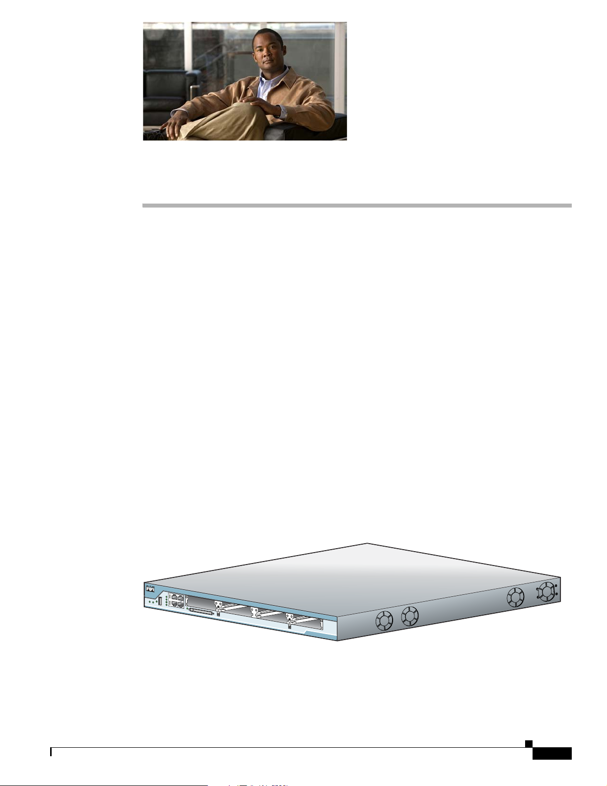
The Cisco IAD2801 series integrated access devices is a fixed configuration router that provides three
models with a common front panel. The front panel, labeled “Cisco IAD2801 series integrated access
devices,” is identical for all models. However, the back panels, labeled by specific model number, vary
depending on interfaces, ports, and options. The Cisco IAD2801 series integrated access devices support
the following configurations:
• IAD2801-2BRI-A/K9—Fixed configuration router, with integrated PVDM2-8, HWIC-1ADSL, and
1 VIC2-2BRI-NT/TE-P, 2 Fast Ethernet connections, and 1 factory configurable or
field-upgradeable HWIC slot.
• IAD2801-4BRI-A/K9—Fixed configuration router, with integrated PVDM2-16, HWIC-1ADSL,
and 2 VIC2-2BRI-NT/TE-P, 2 Fast Ethernet connections, and 1 factory configurable or
field-upgradeable HWIC slot.
• IAD2801-4BRI-S/K9—Fixed configuration router, with integrated PVDM2-16, HWIC-4SHDSL ,
and 2 VIC2-2BRI-NT/TE-P, 2 Fast Ethernet connections, and 1 factory configurable or
field-upgradeable HWIC slot.
The following cards are configurable or field upgradeable in slot 3 on all models:
• HWIC-4ESW
• VIC-4FXS/DID
• HWIC-AP-AG-E or HWIC-AP-G-E
Figure 1-1 Front View of the Cisco IAD2801.
Figure 1-1 Front View of a Cisco IAD2801
95817
This chapter describes the features and specifications of the routers and includes the following sections:
• Hardware Features, page 1-2
• Chassis Views, page 1-5
OL-12433-01
Cisco IAD2801 Series Integrated Access Devices Hardware Installation Guide
1-1
Page 24
Hardware Features
• Interface Numbering, page 1-6
• Specifications, page 1-7
Hardware Features
This section describes the basic features of Cisco IAD2801, including product identification, built-in
interfaces, modules, memory, LED indicators, chassis ventilation, and the internal clock.
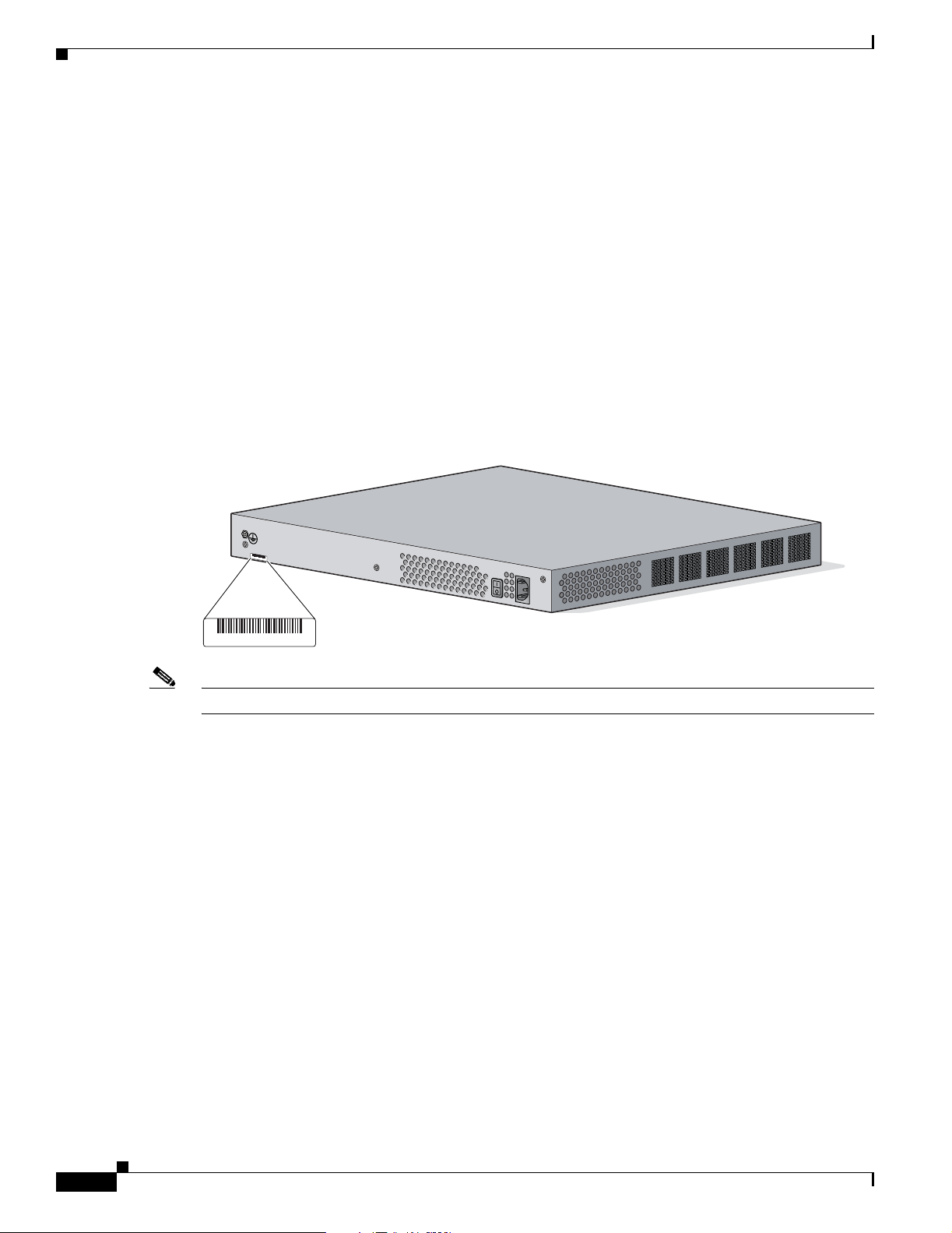
Product Serial Number Location
The serial number label for Cisco IAD2801 is located on the rear of the chassis, along the bottom edge
near the lower left corner. (See Figure 1-2.)
Figure 1-2 Serial Number Location on the Cisco IAD2801
Chapter 1 Overview
S
N
:
A
A
A
N
N
N
N
X
X
X
X
SN: AAANNNNXXXX
Note The serial number for Cisco IAD2801 is 11 characters long.
Cisco Product Identification Tool
The Cisco Product Identification (CPI) tool provides detailed illustrations and descriptions showing
where to locate serial number labels on Cisco products. It includes the following features:
• A search option that allows browsing for models using a tree-structured product hierarchy
• A search field on the final results page making it easier to look up multiple products
• End-of-sale products are clearly identified in results lists
The tool streamlines the process of locating serial number labels and identifying products. Serial number
information expedites the entitlement process and is important for access to support services.
The Cisco Product Identification tool can be accessed at the following URL:
http://tools.cisco.com/Support/CPI/index.do
230309 781-00500-01
1-2
Cisco IAD2801 Series Integrated Access Devices Hardware Installation Guide
OL-12433-01
Page 25

Chapter 1 Overview
Built-in Interfaces
Table 1-1 summarizes the interface ports built into the chassis.
Table 1-1 Summary of Cisco IAD2801 Built-In Interfaces
Hardware Features
IAD2801
100BASE-T Fast Ethernet (FE)
Ports (RJ-45)
Universal Serial
Bus (USB) Ports
Console Port
(RJ-45)
IAD2801-2BRI-A/K9 2 1 1 1
IAD2801-4BRI-A/K9 2 1 1 1
IAD2801-4BRI-S/K9 2 1 1 1
Memory
Cisco IAD2801 contain the following types of memory:
• DRAM—Stores the running configuration and routing tables and is used for packet buffering by the
network interfaces. Cisco IOS software executes from DRAM memory.
• Boot/NVRAM—Internal flash memory. Stores the bootstrap program (ROM monitor), the
configuration register, and the startup configuration.
• Flash memory—External flash memory. Stores the operating system software image.
Table 1-2 summarizes the memory options for Cisco IAD2801. The default memory numbers for RAM
represent the minimum usable memory. You can install additional RAM in multiples of the default
amount, up to the maximum amount.
Table 1-2 Router Memory Specifications
Router
Platform DRAM Boot/NVRAM Flash Memory
Cisco
IAD2801
1. Cisco IAD2801 has 128 MB of SDRAM soldered onto the system board. You can install a DIMM into the expansion slot to
increase memory to the maximum of 384 MB.
Type—SDRAM DIMM
DIMM size—256 MB
DIMM expansion slots—1
1
Default onboard memory—128 MB
Maximum memory—384 MB
Internal 4-MB
flash memory
Auxiliary Port
(RJ-45)
External CompactFlash
memory cards of the
following optional
sizes:
• 64 MB (default)
OL-12433-01
Cisco IAD2801 Series Integrated Access Devices Hardware Installation Guide
1-3
Page 26

Hardware Features
LED Indicators
Chapter 1 Overview
Table 1-3 summarizes the LED indicators that are located in the router bezel or chassis.
For LED troubleshooting information, including possible trouble causes and corrective actions, see
Table A-1 in the “Troubleshooting” document.
Table 1-3 Summary of Cisco IAD2801 LED Indicators
LED Color Description Location
SYS PWR Green Router has successfully booted up and the
software is functional. This LED blinks while
booting or in the ROM monitor.
SYS ACT Green Blinking when any packets are transmitted or received
on any WAN or LAN or system is monitoring internal
activities.
CF Green On when flash memory is busy. Do not
remove the CompactFlash memory card when this
light is on.
AUX/PWR Gree n/
Amber
FE 0 Link Green On when the router is correctly connected to a
FE 0 100 Green On indicates a 100-Mbps link.
FE 0 FDX Green On indicates full-duplex operation.
FE 1 Link Green On when the router is correctly connected to a
FE 1 100 Green On indicates a 100-Mbps link.
FE 1 FDX Green On indicates full-duplex operation.
PVDM 0 Green On indicates presence of a packet voice data
LED is off because inline power is not supported on
the Cisco IAD2801.
local Ethernet LAN through Ethernet port 0.
Off indicates a 10-Mbps link.
Off indicates half-duplex operation.
local Ethernet LAN through Ethernet port 1.
Off indicates a 10-Mbps link.
Off indicates half-duplex operation.
module (PVDM) in PVDM slot 0.
Front
Front
Front
Front
Front
Front
Front
Front
Front
Front
Front
Chassis Ventilation
Internal multispeed fans provide chassis cooling, controlled by an onboard temperature sensor.
The Cisco IAD2801 has two fans. The Cisco IAD2801 internal fans operate at three different speeds,
running at the slower speeds to conserve power and reduce fan noise at ambient temperatures below
o
40
C. They operate at the highest speed in ambient temperatures above 40oC.
Cisco IAD2801 Series Integrated Access Devices Hardware Installation Guide
1-4
OL-12433-01
Page 27

Chapter 1 Overview
Real-Time Clock
An internal real-time clock with battery backup provides the system software with time of day on system
power up. This allows the system to verify the validity of the certification authority (CA) certificate. The
Cisco IAD2801 has a socketed lithium battery. This battery lasts the life of the router under the operating
environmental conditions specified for the router, and is not field-replaceable.
Note If the lithium battery in a Cisco IAD2801 should fail, the router must be returned to Cisco for repair.
Although the battery is not intended to be field-replaceable, the following warning must be heeded:
Chassis Views
Warning
There is the danger of explosion if the battery is replaced incorrectly. Replace the battery only with
the same or equivalent type recommended by the manufacturer. Dispose of used batteries according
to the manufacturer’s instructions.
Chassis Views
This section contains views of the front and rear panels of the Cisco IAD2801, showing locations of the
power and signal interfaces, module slots, status indicators, and chassis identification labels.
Cisco IAD2801 Chassis
Figure 1-3 shows the front panel of a Cisco IAD2801. Figure 1-4 shows the back panel.
Figure 1-3 Front Panel of the Cisco IAD2801
Statement 1015
6
5
1234
OL-12433-01
7 9 11 12 13
8 10
1 Slot 0 8 Auxiliary Power (AUX/PWR) LED
2 Slot 1 9 Universal serial bus (USB) port
3 Slot 2 10 PVDM LEDs
4 Slot 3 11 Auxiliary port
5 Console port 12 Compact flash (CF) LED
6 Fast Ethernet ports and LEDs 13 External CompactFlash memory card slot
7 System LEDs
Cisco IAD2801 Series Integrated Access Devices Hardware Installation Guide
230439
1-5
Page 28

Interface Numbering
Chapter 1 Overview
Figure 1-4 Back Panel of the Cisco IAD2801
3
1 Input power connector 3 Chassis ground connection
2 On/Off switch
Interface Numbering
Table 1-4 summarizes the interface numbering on a Cisco IAD2801.
Note On the Cisco IAD2801, the numbering format for slots is interface type 0/slot/port. “0” indicates slots
that are built into the chassis of a router. On the Cisco IAD2801, all slots begin with “0,” because all
slots are built into the chassis.
Caution The following message will appear during bootup for any unsupported card detected:
2
1
95905
Card is not supported in slot 2. Please remove it.
This message will appear for each unsupported card detected.
If smart-init is enabled on your IAD2801, the following message will appear during bootup for any
unsupported card detected:
Smart Init is enabled
smart init is sizing iomem
ID MEMORY_REQ TYPE
0X003AA110 public buffer pools
0X00211000 public particle pools
0X00020000 Crypto module pools
0X00120000 VPM buffer pools
0X05B3 0X000034A0 Card in slot 0
0X04C8 0X00077D00 Card in slot 1
0X05B3 0X00000000 UNKNOWN Card in slot 2
0X003A 0X00000000 Card in slot 3
0X000021B8 Onboard USB
Table 1-4 summarizes the interface numbering on a Cisco IAD2801.
1-6
Cisco IAD2801 Series Integrated Access Devices Hardware Installation Guide
OL-12433-01
Page 29

Chapter 1 Overview
Specifications
Table 1-4 Interface Numbering on the Cisco IAD2801
Model Slot0 Slot1 Slot2 Slot3
IAD2801-2BRI-A/K9 VIC2-2BRI-NT/TE-P HWIC-1ADSL Not available LTD option
IAD2801-4BRI-A/K9 VIC2-2BRI-NT/TE-P HWIC-1ADSL VIC2-2BRI-NT/TE-P LTD option
IAD2801-4BRI-S/K9 VIC2-2BRI-NT/TE-P HWIC-4SHDSL VIC2-2BRI-NT/TE-P LTD option
1. The factory installable or field upgradeable LTD option includes: HWIC-AP-AG-E and HWIC-AP-G-E, HWIC-4ESW, and VIC-4FXS/DID.
1
1
1
Specifications
Table 1-5, list Cisco IAD2801 specifications.
Table 1-5 Cisco IAD2801 Specifications
Description Specification
Dimensions (H x W x D) 1.72 x 17.49 x 16.5 in. (4.4 x 44.4 x 41.9 cm).
Weight 10.9 lb (4.9 kg) with standard power supply if fully populated with
modules
AC input power
• Input voltage
• Frequency
• Input current
• Inrush surge current
Power consumption 105 W with standard power supply (maximum)
Console and auxiliary ports RJ-45 connector
Operating humidity 5 to 95%, noncondensing
Operating temperature 32 to 104° F (0 to 40° C)
Nonoperating temperature –40 to 162° F (–40 to 72° C)
Noise level, standard power
supply
Safety compliance UL 60950-1; CAN/CSA C22.2 No. 60950-1; IEC 60950-1;
EMC compliance FCC Part 15; ICES-003 Class A; EN50082-1; EN55022 Class A;
100 to 240 VAC, autoranging
47 to 63 Hz
2 A
50 A maximum, one cycle (–48V power included)
39 dBA for local temperatures < 90° F (32° C)
47 dBA for local temperatures between 90° F and 116° F (47° F)
52.6 dBA for temperatures above 116° F (47° F)
EN 60950-1; AS/NZS 60950.1
CISPR22 Class A; EN55024/CISPR24; AS/NZS 3548 Class A;
VCCI Class A; EN 300386; EN61000-3-3; EN61000-3-2;
EN61000-6-2
OL-12433-01
Cisco IAD2801 Series Integrated Access Devices Hardware Installation Guide
1-7
Page 30

Specifications
Chapter 1 Overview
1-8
Cisco IAD2801 Series Integrated Access Devices Hardware Installation Guide
OL-12433-01
Page 31

Warning
CHAPTER
2
Preinstallation Requirements and Planning
This document describes site requirements and equipment needed to install your Cisco IAD2801. It
includes the following sections:
• Safety Recommendations, page 2-1
• General Site Requirements, page 2-3
• Installation Checklist, page 2-4
• Creating a Site Log, page 2-5
• Inspecting the Router, page 2-6
• Required Tools and Equipment for Installation and Maintenance, page 2-6
Only trained and qualified personnel should be allowed to install, replace, or service this equipment.
Statement 1030
Safety Recommendations
Follow these guidelines to ensure general safety:
• Keep the chassis area clear and dust-free during and after installation.
• If you remove the chassis cover, put it in a safe place.
• Keep tools and chassis components away from walk areas.
• Do not wear loose clothing that could get caught in the chassis. Fasten your tie or scarf and roll up
your sleeves.
• Wear safety glasses when working under conditions that might be hazardous to your eyes.
• Do not perform any action that creates a hazard to people or makes the equipment unsafe.
Note For safety information you must know before working on your Cisco router, see the Cisco 2800 and
Cisco 3800 Series Integrated Services Routers Regulatory Compliance and Safety Information
document.
OL-12433-01
Cisco IAD2801 Series Integrated Access Devices Hardware Installation Guide
2-1
Page 32

Safety Recommendations
Safety with Electricity
Chapter 2 Preinstallation Requirements and Planning
Warning
Read the installation instructions before connecting the system to the power source.
Statement 1004
Follow these guidelines when working on equipment powered by electricity:
• Locate the emergency power-off switch in the room in which you are working. Then, if an electrical
accident occurs, you can quickly turn off the power.
• Disconnect all power before doing the following:
–
Installing or removing a chassis
–
Working near power supplies
• Look carefully for possible hazards in your work area, such as moist floors, ungrounded power
extension cables, frayed power cords, and missing safety grounds.
• Do not work alone if hazardous conditions exist.
• Never assume that power is disconnected from a circuit. Always check.
• Never open the enclosure of the router’s internal power supply.
• If an electrical accident occurs, proceed as follows:
–
Use caution; do not become a victim yourself.
–
Turn off power to the device.
–
If possible, send another person to get medical aid. Otherwise, assess the victim’s condition and
then call for help.
–
Determine if the person needs rescue breathing or external cardiac compressions; then take
appropriate action.
In addition, use the following guidelines when working with any equipment that is disconnected from a
power source, but still connected to telephone wiring or other network cabling:
• Never install telephone wiring during a lightning storm.
• Never install telephone jacks in wet locations unless the jack is specifically designed for it.
• Never touch uninsulated telephone wires or terminals unless the telephone line is disconnected at
the network interface.
• Use caution when installing or modifying telephone lines.
Preventing Electrostatic Discharge Damage
Electrostatic discharge (ESD) can damage equipment and impair electrical circuitry. It can occur if
electronic printed circuit cards are improperly handled and can cause complete or intermittent failures.
Always follow ESD prevention procedures when removing and replacing modules:
• Ensure that the router chassis is electrically connected to earth ground.
• Wear an ESD-preventive wrist strap, ensuring that it makes good skin contact. Connect the clip to
an unpainted surface of the chassis frame to channel unwanted ESD voltages safely to ground. To
guard against ESD damage and shocks, the wrist strap and cord must operate effectively.
• If no wrist strap is available, ground yourself by touching a metal part of the chassis.
2-2
Cisco IAD2801 Series Integrated Access Devices Hardware Installation Guide
OL-12433-01
Page 33

Chapter 2 Preinstallation Requirements and Planning
Caution For the safety of your equipment, periodically check the resistance value of the antistatic strap. It should
be between 1 and 10 megohms (Mohm).
General Site Requirements
This section describes the requirements your site must meet for safe installation and operation of your
router. Ensure that the site is properly prepared before beginning installation. If you are experiencing
shutdowns or unusually high errors with your existing equipment, this section can also help you isolate
the cause of failures and prevent future problems.
Power Supply Considerations
Check the power at your site to ensure that you are receiving “clean” power (free of spikes and noise).
Install a power conditioner if necessary.
The AC power supply includes the following features:
General Site Requirements
• Autoselects either 110 V or 220 V operation.
• All units include a 6-foot (1.8-meter) electrical power cord. (A label near the power inlet indicates
the correct voltage frequency, current draw, and power dissipation for the unit.)
Site Environment
Cisco IAD2801 series integrated access devices can be placed on a desktop or installed in a rack. The
location of your router and the layout of your equipment rack or wiring room are extremely important
considerations for proper operation. Equipment placed too close together, inadequate ventilation, and
inaccessible panels can cause malfunctions and shutdowns, and can make maintenance difficult. Plan for
access to both front and rear panels of the router.
When planning your site layout and equipment locations, remember the precautions described in the next
section “Site Configuration,” to help avoid equipment failures and reduce the possibility of
environmentally caused shutdowns. If you are currently experiencing shutdowns or an unusually high
number of errors with your existing equipment, these precautions may help you isolate the cause of the
failures and prevent future problems.
Site Configuration
The following precautions will help you plan an acceptable operating environment for your router and
will help you avoid environmentally caused equipment failures:
OL-12433-01
• Ensure that the room where your router operates has adequate air circulation. Electrical equipment
generates heat. Without adequate air circulation, ambient air temperature may not cool equipment
to acceptable operating temperatures.
• Always follow ESD-prevention procedures described in the “Preventing Electrostatic Discharge
Damage” section on page 2-2 to avoid damage to equipment. Damage from static discharge can
cause immediate or intermittent equipment failure.
Cisco IAD2801 Series Integrated Access Devices Hardware Installation Guide
2-3
Page 34

Installation Checklist
• Ensure that the chassis cover and module rear panels are secure. All empty network module slots,
Equipment Racks
Cisco IAD2801 series integrated access devices include brackets for use with a 19-inch rack.
Note Brackets for a 23-inch rack are not available for Cisco IAD2801 series integrated access devices.
The following information will help you plan your equipment rack configuration:
• Allow clearance around the rack for maintenance.
• Allow at least one rack unit of vertical space between routers.
• Enclosed racks must have adequate ventilation. Ensure that the rack is not congested, because each
Chapter 2 Preinstallation Requirements and Planning
interface card slots, and power supply bays must have filler panels installed. The chassis is designed
to allow cooling air to flow within it, through specially designed cooling slots. A chassis with
uncovered openings permits air leaks, which may interrupt and reduce the flow of air across internal
components.
router generates heat. An enclosed rack should have louvered sides and a fan to provide cooling air.
Heat generated by equipment near the bottom of the rack can be drawn upward into the intake ports
of the equipment above.
• When mounting a chassis in an open rack, ensure that the rack frame does not block the intake or
exhaust ports. If the chassis is installed on slides, check the position of the chassis when it is seated
into the rack.
• Baffles can help to isolate exhaust air from intake air, which also helps to draw cooling air through
the chassis. The best placement of the baffles depends on the airflow patterns in the rack, which can
be found by experimenting with different configurations.
• When equipment installed in a rack (particularly in an enclosed rack) fails, try operating the
equipment by itself, if possible. Power off other equipment in the rack (and in adjacent racks) to
allow the router under test a maximum of cooling air and clean power.
Installation Checklist
The sample installation checklist lists items and procedures for installing a new router. Make a copy of
this checklist and mark the entries when completed. Include a copy of the checklist for each router in
your Site Log (described in the next section, “Creating a Site Log”).
Installation checklist for site_____________________________________________
Router name_______________________________________________________
Task Verified by Date
Installation Checklist copied
Background information placed in Site Log
Site power voltages verified
Installation site power check completed
2-4
Cisco IAD2801 Series Integrated Access Devices Hardware Installation Guide
OL-12433-01
Page 35

Chapter 2 Preinstallation Requirements and Planning
Installation checklist for site_____________________________________________
Router name_______________________________________________________
Task Verified by Date
Required tools available
Additional equipment available
Router received
Product registration card received
Cisco.com contact information label received
Chassis components verified
Initial electrical connections established
ASCII terminal (for local configuration) or
modem (for remote configuration) available
Signal distance limits verified
Startup sequence steps completed
Initial operation verified
Software image verified
Creating a Site Log
Creating a Site Log
The Site Log provides a record of all actions related to the router. Keep it in an accessible place near the
chassis where anyone who performs tasks has access to it. Use the Installation Checklist to verify steps
in the installation and maintenance of the router. Site Log entries might include the following
information:
• Installation progress—Make a copy of the Installation Checklist and insert it into the Site Log. Make
entries as each procedure is completed.
• Upgrade and maintenance procedures—Use the Site Log as a record of ongoing router maintenance
and expansion history. A Site Log might include the following events:
–
Installation of network modules
–
Removal or replacement of network modules and other upgrades
–
Configuration changes
–
Maintenance schedules and requirements
–
Maintenance procedures performed
–
Intermittent problems
–
Comments and notes
OL-12433-01
Cisco IAD2801 Series Integrated Access Devices Hardware Installation Guide
2-5
Page 36

Inspecting the Router
Inspecting the Router
Do not unpack the router until you are ready to install it. If the final installation site will not be ready
for some time, keep the chassis in its shipping container to prevent accidental damage. When you are
ready to install the router, proceed with unpacking it.
The router, cables, publications, and any optional equipment you ordered may be shipped in more than
one container. When you unpack the containers, check the packing list to ensure that you received all the
following items:
• Router
• 6-foot (1.8-meter) power cord for AC power)
• Rubber feet for desktop mounting
• Rack-mount brackets with screws for 19-inch racks
• Cable management bracket
• RJ-45-to-DB-9 console cable
• DB-9-to-DB-25 connector adapter
Chapter 2 Preinstallation Requirements and Planning
• Optional equipment (such as network connection cables or additional rack-mount brackets)
Inspect all items for shipping damage. If anything appears to be damaged, or if you encounter problems
installing or configuring your router, contact customer service. Warranty, service, and support
information is in the quick start guide that shipped with your router.
Required Tools and Equipment for Installation and Maintenance
You need the following tools and equipment to install and upgrade the router and its components:
• ESD-preventive cord and wrist strap
• Number 2 Phillips screwdriver
• Flat-blade screwdrivers: small, 3/16-in. (4 - 5 mm) and medium, 1/4-in. (6 - 7 mm)
–
To install or remove modules
–
To remove the cover, if you are upgrading memory or other components
• Screws that fit your rack
• Wire crimper
• Wire for connecting the chassis to an earth ground:
–
AWG 6 (1 3 mm2) wire for NEBS-compliant chassis grounding
–
AWG 14 (2 mm2) or larger wire for NEC-compliant chassis grounding
2-6
–
AWG 18 (1 mm2) or larger wire for EN/IEC 60950-compliant chassis grounding
• For NEC-compliant grounding, an appropriate user-supplied ring terminal, with an inner diameter
of 1/4 in. (5-7 mm)
In addition, depending on the type of modules you plan to use, you might need the following equipment
to connect a port to an external network:
• Cables for connection to the WAN and LAN ports (dependent on configuration)
Cisco IAD2801 Series Integrated Access Devices Hardware Installation Guide
OL-12433-01
Page 37

Chapter 2 Preinstallation Requirements and Planning
Note For more information on cable specifications, refer to the online document Cisco Modular
Access Router Cable Specifications on Cisco.com.
• Ethernet hub or PC with a network interface card for connection to an Ethernet (LAN) port.
• Console terminal (an ASCII terminal or a PC running HyperTerminal or similar terminal emulation
software) configured for 9600 baud, 8 data bits, 1 stop bit, no flow control, and no parity.
• Modem for connection to the auxiliary port for remote administrative access (optional).
Required Tools and Equipment for Installation and Maintenance
OL-12433-01
Cisco IAD2801 Series Integrated Access Devices Hardware Installation Guide
2-7
Page 38

Required Tools and Equipment for Installation and Maintenance
Chapter 2 Preinstallation Requirements and Planning
2-8
Cisco IAD2801 Series Integrated Access Devices Hardware Installation Guide
OL-12433-01
Page 39

CHAPTER
Port and Cable Information
This document provides information about cables needed to install your Cisco IAD2801. It includes the
following sections:
• Console and Auxiliary Port Considerations, page 3-1
• Preparing to Connect to a Network, page 3-2
Console and Auxiliary Port Considerations
The router includes an console port and an auxiliary port. The console and auxiliary ports provide access
to the router either locally using a console terminal connected to the console port, or remotely using a
modem connected to the auxiliary port. This section discusses important cabling information to consider
before connecting the router to a console terminal or modem.
The main difference between the console and auxiliary ports is that the auxiliary port supports hardware
flow control and the console port does not. Flow control paces the transmission of data between a
sending device and a receiving device. Flow control ensures that the receiving device can absorb the data
sent to it before the sending device sends more. When the buffers on the receiving device are full, a
message is sent to the sending device to suspend transmission until the data in the buffers has been
processed. Because the auxiliary port supports flow control, it is ideally suited for use with the
high-speed transmissions of a modem. Console terminals send data at slower speeds than modems;
therefore, the console port is ideally suited for use with console terminals.
3
Console Port Connections
For connection to a PC running terminal emulation software, your router is provided with an RJ-45 to
DB-9 adapter cable.
To connect the router to an ASCII terminal, use the RJ-45-to-DB-9 cable and a DB-9-to-DB-25 adapter.
The default parameters for the console port are 9600 baud, 8 data bits, 1 stop bit, and no parity. The
console port does not support hardware flow control. For detailed information about installing a console
terminal, see the “Connecting to a Console Terminal or Modem” section on page 5-3.
For cable and port pinouts, refer to the online document Cisco Modular Access Router Cable
Specifications. This document is located on Cisco.com.
OL-12433-01
Cisco IAD2801 Series Integrated Access Devices Hardware Installation Guide
3-1
Page 40

Preparing to Connect to a Network
Auxiliary Port Connections
For connection to a modem, your router is provided with an RJ-45-to-DB-25 adapter cable. (A
DB-9-to-DB-25 adapter is also included with the Cisco IAD2801.)
For detailed information about connecting devices to the auxiliary port, see the “Connecting to a Console
Terminal or Modem” section on page 5-3 of the “Cable Connection Procedures” online document.
For cable and port pinouts, refer to the Cisco Modular Access Router Cable Specifications online
document on Cisco.com.
Preparing to Connect to a Network
When setting up your router, consider distance limitations and potential electromagnetic interference
(EMI) as defined by the applicable local and international regulations.
Refer to the following online documents for more information about network connections and interfaces:
• Cisco Network Modules Hardware Installation Guide
• Cisco Interface Cards Installation Guide
Chapter 3 Port and Cable Information
• Cisco Modular Access Router Cable Specifications
Note For information about connecting DSL interface cards, see the Cisco Interface Cards Hardware
Installation Guide at the following URL:
http://www.cisco.com/en/US/products/hw/modules/ps2641/products_module_installation_guide_book
09186a0080692b21.html
Warning
To avoid electric shock, do not connect safety extra-low voltage (SELV) circuits to telephone-network
voltage (TNV) circuits. LAN ports contain SELV circuits, and WAN ports contain TNV circuits. Some
LAN and WAN ports both use RJ-45 connectors.
Ethernet Connections
The IEEE has established Ethernet as standard IEEE 802.3. Cisco IAD2801 series integrated access
devices support the following Ethernet implementations:
• 100BASE-T—100 Mbps full-duplex transmission over a Category 5 or better unshielded
twisted-pair (UTP) cable. Supports the Ethernet maximum length of 328 feet (100 meters).
• 10BASE-T—10 Mbps full-duplex transmission over a Category 5 or better unshielded twisted-pair
(UTP) cable. Supports the Ethernet maximum length of 328 feet (100 meters).
Statement 1021
3-2
Refer to the Cisco Modular Access Router Cable Specifications online document for information about
Ethernet cables, connectors, and pinouts.
Cisco IAD2801 Series Integrated Access Devices Hardware Installation Guide
OL-12433-01
Page 41

Warning
Warning
CHAPTER
4
Chassis Installation Procedures
This document describes how to install your Cisco IAD2801 on a desktop or in a rack. It includes the
following sections:
• Setting Up the Chassis, page 4-1
• Installing the Chassis Ground Connection, page 4-5
Only trained and qualified personnel should be allowed to install, replace, or service this equipment.
Statement 1030
This unit is intended for installation in restricted access areas. A restricted access area can be
accessed only through the use of a special tool, lock and key, or other means of security.
Statement 1017
Setting Up the Chassis
You can set any Cisco IAD2801 on a desktop or install it in a rack. See the applicable instructions in the
following sections.
• Rack-Mounting the Chassis
• Setting the Chassis on a Desktop
Caution To prevent damage to the chassis, never attempt to lift or tilt the chassis by the plastic panel on the front.
Always hold the chassis by the metal body.
Warning
Before working on a system that has an on/off switch, turn OFF the power and unplug the power cord.
Statement 1
OL-12433-01
Cisco IAD2801 Series Integrated Access Devices Hardware Installation Guide
4-1
Page 42

Setting Up the Chassis
Rack-Mounting the Chassis
If you are planning to rack-mount the router, do so before making network and power connections.
Internal modules should be installed prior to rack-mounting.
Cisco IAD2801 series integrated access devices can be installed only in 19-inch racks, and cannot be
center mounted. Use the standard brackets shipped with the router for mounting the chassis in a 19-inch
rack.
Note Brackets for 23-inch (58.42-cm) equipment racks are not available for the Cisco IAD2801.
You can mount the router in the following ways:
• Front mounting—Brackets attached at the front of the chassis with the front panel facing forward.
• Rear mounting—Brackets attached at the rear of the chassis with the rear panel facing forward.
The brackets are shown in Figure 4-1.
Figure 4-1 Rack-Mounting Brackets for the Cisco IAD2801 for a 19-Inch Rack
Chapter 4 Chassis Installation Procedures
95769
Attaching Rack-Mount Brackets to Cisco IAD2801 Series Integrated Access Devices
Use four of the supplied number-8 Phillips flat-head screws to attach the long side of each bracket to the
router. Figure 4-2 shows how to attach the brackets to the sides of the router with the front panel forward.
Figure 4-2 Attaching Rack-Mounting Brackets to a Cisco IAD2801
R
95770
4-2
Cisco IAD2801 Series Integrated Access Devices Hardware Installation Guide
OL-12433-01
Page 43

Chapter 4 Chassis Installation Procedures
Installing the Router in a Rack
After you have attached the brackets to the router chassis, use the screws provided with the rack to install
the chassis in the rack.
Tip Start the lower pair of screws first, and rest the brackets on the lower screws while you insert the upper
pair of screws.
Tip The screw slots in the brackets are spaced to line up with every second pair of screw holes in the rack.
When the correct screw holes are used, the small threaded holes in the brackets line up with unused screw
holes in the rack. If the small holes do not line up with the rack holes, you must raise or lower the
brackets to the next rack hole.
Setting Up the Chassis
Warning
Caution Be sure to leave space above and below each router in a rack, to allow for cooling air circulation.
To prevent bodily injury when mounting or servicing this unit in a rack, you must take special
precautions to ensure that the system remains stable. The following guidelines are provided to
ensure your safety:
• This unit should be mounted at the bottom of the rack if it is the only unit in the rack.
• When mounting this unit in a partially filled rack, load the rack from the bottom to the top with the heaviest
component at the bottom of the rack.
• If the rack is provided with stabilizing devices, install the stabilizers before mounting or servicing the unit in
the rack.
Statement 1006
Attaching Optional Cable Management Bracket
The optional cable management bracket provides attachment points for organizing and routing cables.
On brackets for the Cisco IAD2801, attach the cable management bracket to the left or right rack-mount
bracket using the screw provided, as shown in Figure 4-3.
OL-12433-01
Cisco IAD2801 Series Integrated Access Devices Hardware Installation Guide
4-3
Page 44

Chapter 4 Chassis Installation Procedures
Setting Up the Chassis
Figure 4-3 Attaching the Optional Cable Management Bracket to the Cisco IAD2801
Cable management screw
Chassis Grounding
After the router is installed, you must connect the chassis to a reliable earth ground. For the chassis
ground connection procedures, see the “Installing the Chassis Ground Connection” section on page 4-5.
95772
Setting the Chassis on a Desktop
You can place a Cisco IAD2801 on a desktop or shelf. If you are placing a Cisco IAD2801 on a desktop,
you must first install the four rubber feet that are supplied in the accessory kit. They provide space for
air circulation and antiskid protection. Peel the rubber feet from the adhesive strip, and stick them onto
the features marked “+” on the bottom of the chassis.
Warning
Caution Do not place anything on top of the router that weighs more than 10 pounds (4.5 kg), and do not stack
Caution Your chassis installation must allow unrestricted airflow for chassis cooling. For placing the router on a
To prevent personal injury or damage to the chassis, never attempt to lift or tilt the chassis using the
handles on modules (such as power supplies, fans, or cards); these types of handles are not designed
to support the weight of the unit.
routers on a desktop. Excessive distributed weight of more than 10 pounds, or pound point load of
10 pounds on top could damage the chassis.
desktop, keep at least 1 inch (2.54 cm) of clear space beside the cooling inlet and exhaust vents.
After the router is installed, you must connect the chassis to a reliable earth ground. For the chassis
ground connection procedures, see the “Installing the Chassis Ground Connection” section on page 4-5.
Statement 1032
4-4
Cisco IAD2801 Series Integrated Access Devices Hardware Installation Guide
OL-12433-01
Page 45

Chapter 4 Chassis Installation Procedures
Installing the Chassis Ground Connection
Installing the Chassis Ground Connection
Warning
This equipment must be grounded. Never defeat the ground conductor or operate the equipment in the
absence of a suitably installed ground conductor. Contact the appropriate electrical inspection
authority or an electrician if you are uncertain that suitable grounding is available.
Statement 1024
You must connect the chassis to a reliable earth ground; the ground wire must be installed in accordance
with local electrical safety standards.
Note NEBS-compliant grounding is not supported on the Cisco IAD2801.
• For NEC-compliant grounding, use size 14 AWG (2 mm
2
) or larger copper wire and an appropriate
user-supplied ring terminal with an inner diameter of 1/4 in. (5–7 mm).
• For EN/IEC 60950-compliant grounding, use size 18 AWG (1 mm
2
) or larger copper wire and an
appropriate user-supplied ring terminal.
To install the ground connection for a Cisco IAD2801, perform the following steps:
Step 1 Strip one end of the ground wire to the length required for the ground lug or terminal.
• For the NEBS ground lug—approximately 0.75 in. (20 mm)
• For user-provided ring terminal—as required
Step 2 Crimp the ground wire to the ground lug or ring terminal, using a crimp tool of the appropriate size.
Step 3 Attach the ground lug or ring terminal to the chassis as shown in Figure 4-4. For a ground lug, use the
two screws with captive locking washers provided. For a ring terminal, use one of the screws provided.
Tighten the screws to a torque of 8 to 10 in-lb (0.9 to 1.1 N-m).
Step 4 Connect the other end of the ground wire to a known reliable earth ground point at your site.
Figure 4-4 Chassis Ground Connection Using a Ring Terminal on the Cisco IAD2801
Ring terminal
attachment
After the router has been installed and properly grounded, you can connect the power wiring; the WAN,
LAN, and voice cables; and the cables for administrative access as required for your installation. For
information about connecting the cables, see the “Cable Connection Procedures” online document.
117082
OL-12433-01
Cisco IAD2801 Series Integrated Access Devices Hardware Installation Guide
4-5
Page 46

Installing the Chassis Ground Connection
Chapter 4 Chassis Installation Procedures
4-6
Cisco IAD2801 Series Integrated Access Devices Hardware Installation Guide
OL-12433-01
Page 47

Warning
Warning
CHAPTER
5
Cable Connection Procedures
This document describes how to connect your Cisco IAD2801 series integrated access devices to a power
source and to networks and external devices. It includes the following sections:
• Power Connections, page 5-1
• Connecting WAN, LAN, and Voice Cables, page 5-2
• Connecting to a Console Terminal or Modem, page 5-3
Only trained and qualified personnel should be allowed to install, replace, or service this equipment.
Statement 1030
This unit is intended for installation in restricted access areas. A restricted access area can be
accessed only through the use of a special tool, lock and key, or other means of security.
Statement 1017
Power Connections
This section explains how to connect AC power to a Cisco IAD2801.
Warning
Note The installation must comply with all required electrical codes applicable at the installation site.
OL-12433-01
Read the installation instructions before connecting the system to the power source.
Statement 1004
Cisco IAD2801 Series Integrated Access Devices Hardware Installation Guide
5-1
Page 48

Connecting WAN, LAN, and Voice Cables
Connecting Routers to AC Power
Connect the Cisco IAD2801 to a 15 A, 120 VAC (10 A, 240 VAC) circuit with overcurrent protection.
Note The input voltage tolerance limits for AC power are 90 and 264 VAC.
Chapter 5 Cable Connection Procedures
Warning
Warning
Warning
AC connected units must have a permanent ground connection in addition to the power cable ground
wire. NEBS-compliant grounding satisfies this requirement.
This product requires short-circuit (overcurrent) protection, to be provided as part of the building
installation. Install only in accordance with national and local wiring regulations.
This product relies on the building’s installation for short-circuit (overcurrent) protection. Ensure that
the protective device is rated not greater than:
15A, 120VAC (10A, 240VAC).
Statement 1005
Connecting WAN, LAN, and Voice Cables
This section describes how to connect the WAN, LAN, and voice interface cables. It covers the following
topics:
• Ports and Cabling, page 5-3
• Connection Procedures and Precautions, page 5-3
Note One or two Ethernet cables are typically provided with the router. Additional cables and transceivers can
be ordered from Cisco. For ordering information, contact customer service. For cable pinouts, refer to
the Cisco Modular Access Router Cable Specifications document.
Statement 284
Statement 1045
5-2
Warning
Warning
Cisco IAD2801 Series Integrated Access Devices Hardware Installation Guide
To avoid electric shock, do not connect safety extra-low voltage (SELV) circuits to telephone-network
voltage (TNV) circuits. LAN ports contain SELV circuits, and WAN ports contain TNV circuits. Some
LAN and WAN ports both use RJ-45 connectors. Use caution when connecting cables.
Hazardous network voltages are present in WAN ports regardless of whether power to the unit is OFF
or ON. To avoid electric shock, use caution when working near WAN ports. When detaching cables,
detach the end away from the unit first.
Statement 1026
Statement 1021
OL-12433-01
Page 49

Chapter 5 Cable Connection Procedures
Ports and Cabling
Table 5-1 summarizes some typical WAN, LAN, and voice connections for Cisco IAD2801 integrated
access devices. The connections summarized here are also described in detail in the following
documents:
• Cisco Modular Access Router Cable Specifications
• Cisco Network Modules Hardware Installation Guide
• Cisco Interface Cards Installation Guide
Table 5-1 WAN, LAN, and Voice Connections
Connecting to a Console Terminal or Modem
Port or Connection Port Type, Color
Ethernet RJ-45, yellow Ethernet hub or Ethernet switch Category 5 or higher Ethernet
ADSL RJ-11C/CA11A,
lavender
SHDSL RJ-45 Network demarcation device for
Analog voice FXS RJ-11, gray Telephone, fax RJ-11; RJ21 if using NM-HDA,
BRI Voice RJ-48C/CA81A, tan, Digital voice RJ-48C straight-through,
1. Cable color codes are specific to Cisco cables.
1
Connection: Cable
Network demarcation device for
service provider DSL interface
service provider DSL interface
RJ-11 straight-through
RJ-45 straight-through
straight-through
Connection Procedures and Precautions
Connect each WAN, LAN, and voice cable to the appropriate connector on the chassis or on a network
module or interface card.
• Position the cables carefully, so that they do not put strain on the connectors.
• Organize cables in bundles so that cables do not intertwine.
• Inspect the cables to make sure that the routing and bend radiuses are satisfactory. Reposition cables,
if necessary.
• Install cable ties in accordance with site requirements.
For cable pinouts, refer to the Cisco Modular Access Router Cable Specifications document.
Connecting to a Console Terminal or Modem
Your router has console and auxiliary ports for system management. These ports provide administrative
access to your router either locally (with a console terminal or PC) or remotely (with a modem).
Cisco provides the following cables for connecting your router to a console terminal, PC, or modem:
• One console cable (RJ-45-to-DB-9, blue)
• One DB-9-to-DB-25 adapter
This section describes how to connect a console terminal or PC to the console port and how to connect
a modem to the auxiliary port. Tabl e 5-2 summarizes the system management connections.
Cisco IAD2801 Series Integrated Access Devices Hardware Installation Guide
OL-12433-01
5-3
Page 50

Chapter 5 Cable Connection Procedures
Connecting to a Console Terminal or Modem
Table 5-2 System Management Connections
Port Color Connected To: Cable
Console Light blue PC or ASCII terminal communication port
(usually labeled COM)
Auxiliary Black Modem for remote access RJ-45-to-DB-25 modem cable or
For information about cable pinouts, refer to the Cisco Modular Access Router Cable Specifications
document.
RJ-45-to-DB-9 console cable
RJ-45-to-DB-9 console cable with a
DB-9-to-DB25 adapter
Connecting to the Console Port
If a console terminal or PC is connected to the console port, you can configure the router locally. To
connect a console terminal or a PC running HyperTerminal or similar terminal emulation software to the
console port on the router, perform the following steps:
Step 1 Use the blue RJ-45-to-DB-9 console cable to connect the router to a terminal.
Note On the Cisco routers, the console port is color-coded blue.
Step 2 Configure your terminal or terminal emulation software for 9600 baud (default), 8 data bits, 1 stop bit,
no parity, and flow control set to “none.”
Note Because hardware flow control is not possible on the console port, do not connect modems to
the console port. Connect modems only to the auxiliary port.
Connecting to the Auxiliary Port
If a modem is connected to the auxiliary port, a remote user can dial in to the router and configure it. To
connect a modem to the auxiliary port on the router, perform the following steps:
Step 1 Use the black RJ-45-to-DB-25 modem cable or the RJ-45-to-DB-9 console cable with a DB-9 to DB-25
adapter to connect the router to a modem.
Step 2 Make sure that your modem and the router auxiliary port are configured for the same transmission speed
(up to 115200 bps is supported) and hardware flow control with data carrier detect (DCD) and data
terminal ready (DTR) operations.
5-4
Cisco IAD2801 Series Integrated Access Devices Hardware Installation Guide
OL-12433-01
Page 51

CHAPTER
6
Power Up and Initial Configuration Procedures
This document describes how to power up your Cisco IAD2801 and perform an initial configuration to
provide network access. It includes the following sections:
• Powering Up Cisco IAD2801 Integrated Access Devices, page 6-1
• Configuring the Router, page 6-4
Powering Up Cisco IAD2801 Integrated Access Devices
Warning
Blank faceplates and cover panels serve three important functions: they prevent exposure to
hazardous voltages and currents inside the chassis; they contain electromagnetic interference (EMI)
that might disrupt other equipment; and they direct the flow of cooling air through the chassis. Do not
operate the system unless all cards, faceplates, front covers, and rear covers are in place.
1029
Statement
This section covers the following topics:
• Checklist for Power Up, page 6-1
• Power Up Procedure, page 6-2
• Verifying the Front Panel LED Indications, page 6-3
• Verifying the Hardware Configuration, page 6-3
Checklist for Power Up
You are ready to power up the Cisco router if the following steps are completed:
• Chassis is securely mounted and grounded.
• Power and interface cables are connected.
• The external CompactFlash memory card is properly seated into its slot. For installation
instructions, see the online document “Removing and Installing CompactFlash Memory Cards.”
• PC with terminal emulation program (hyperTerminal or equivalent) is connected to the console port
and powered up.
• Your PC terminal emulation program is configured for 9600 baud, 8 data bits, 1 stop bit, no parity,
and flow control is set to “none.”
OL-12433-01
Cisco IAD2801 Series Integrated Access Devices Hardware Installation Guide
6-1
Page 52

Powering Up Cisco IAD2801 Integrated Access Devices
• Suitable PC COM port is selected in the terminal emulation program.
• You have selected passwords for access control.
• You have determined the IP addresses for the Ethernet interfaces.
Power Up Procedure
To power up your Cisco router and verify that it goes through its initialization and self-test, follow the
procedure below. When the procedure is finished, the Cisco router is ready to configure.
If you encounter problems when you power on the router, refer to the “Troubleshooting” online
document.
For information about the ROM monitor and the bootstrap program, refer to the Using the ROM Monitor
document. For information about the configuration register, refer to the Changing the Configuration
Register Settings document.
Note To view the boot sequence, you must have a console connection to the Cisco router before it powers up.
Chapter 6 Power Up and Initial Configuration Procedures
Step 1 Make sure that your PC is powered up and connected as described in the “Checklist for Power Up”
section on page 6-1.
Step 2 Move the power switch to the ON position.
The following indications appear:
• The SYS PWR LED on the front of the chassis blinks green.
• The fans operate.
Depending on your installation, some LEDs on the rear of the chassis and on installed modules might
also come on.
If you encounter problems when you power up the router, refer to the “Troubleshooting” online
document.
Startup messages appear in your terminal emulation program window. When the startup messages end,
the SYS PWR LED comes on solid green.
Caution Do not press any keys on the keyboard until the messages stop and the SYS PWR LED is solid green. Any
keys pressed during this time are interpreted as the first command typed when the messages stop, which
might cause the router to power off and start over. It takes a few minutes for the messages to stop.
You may see different startup messages:
• If you see the following messages, the router has booted with a configuration file and is ready for
initial configuration.
yourname con0 is now available
6-2
Press RETURN to get started.
• If you see the following messages, the router has booted and is ready for initial configuration using
the setup command facility or the command-line interface (CLI).
--- System Configuration Dialog ---
Cisco IAD2801 Series Integrated Access Devices Hardware Installation Guide
OL-12433-01
Page 53

Chapter 6 Power Up and Initial Configuration Procedures
At any point you may enter a question mark '?' for help.
Use ctrl-c to abort configuration dialog at any prompt.
Default settings are in square brackets '[]'.
Would you like to enter the initial configuration dialog? [yes/no]:
To learn how to use the setup command facility to configure the router, see the “Initial
Configuration Using the Setup Command Facility” section on page 6-4.
To learn how to use the CLI to configure the router, see the “Initial Configuration Using the Cisco
CLI—Manual Configuration” section on page 6-7.
Note If the rommon 1> prompt appears, your system has booted in ROM monitor mode. For information on the
ROM monitor, see the Using the ROM Monitor document.
Verifying the Front Panel LED Indications
Powering Up Cisco IAD2801 Integrated Access Devices
The front-panel indicator LEDs described in Table 6-1 provide power, activity, and status information
useful during powerup.
Table 6-1 Cisco IAD2801 LED Indicators
LED Label LED Color or State Meaning
SYS
PWR
Solid green System is operating normally
Blinking green System is booting or is in ROM monitor mode
Amber System error
Off Power is off or power fault
SYS
ACT
Blinking green or solid green Packet transfers are occurring or internal monitoring activities are
occurring
Off No packet transfers are occurring
CF Blinking green or solid green Flash memory is being accessed; do not eject the CompactFlash memory
card
Off Flash memory is not being accessed; okay to eject the CompactFlash
memory card
Verifying the Hardware Configuration
OL-12433-01
To display and verify the hardware features, enter the following commands:
• show version—Displays the system hardware version; the installed software version; the names and
sources of configuration files; the boot images; and the amount of installed DRAM, NVRAM, and
flash memory.
• show diag—Lists and displays diagnostic information about the installed controllers, interface
processors, and port adapters; typical examples are network modules, interface cards (VICs and
HWICs).
Cisco IAD2801 Series Integrated Access Devices Hardware Installation Guide
6-3
Page 54

Configuring the Router
Configuring the Router
This section covers the following topics:
• Initial Configuration Using Cisco Router, page 6-4
• Initial Configuration Using the Setup Command Facility, page 6-4
• Initial Configuration Using the Cisco CLI—Manual Configuration, page 6-7
• Verifying the Initial Configuration, page 6-8
• Completing the Configuration, page 6-8
You can configure your router by using one of the following tools:
• Setup command facility—See the “Initial Configuration Using the Setup Command Facility”
section on page 6-4.
• Command-line interface (CLI)—See the “Initial Configuration Using the Cisco CLI—Manual
Configuration” section on page 6-7.
Note If you need help with the interface and port numbering, refer to the “Interface Numbering” section of
the “Overview” online document.
Chapter 6 Power Up and Initial Configuration Procedures
Initial Configuration Using Cisco Router
The following messages appear at the end of the startup sequence:
yourname con0 is now available
Press RETURN to get started.
For help with interface and port numbering, refer to the “Interface Numbering” section of the
“Overview” online document.
Initial Configuration Using the Setup Command Facility
This section shows how to use the setup command facility to configure a hostname for the router, set
passwords, and configure an interface for communication with the management network. If you see the
following messages at the end of the startup sequence, the setup command facility has been invoked
automatically:
--- System Configuration Dialog ---
At any point you may enter a question mark '?' for help.
Use ctrl-c to abort configuration dialog at any prompt.
Default settings are in square brackets '[]'.
Would you like to enter the initial configuration dialog? [yes/no]:
The setup command facility prompts you for basic information about your router and network, and it
creates an initial configuration file. After the configuration file has been created, you can use the CLI or
Cisco Router to perform additional configuration.
6-4
Cisco IAD2801 Series Integrated Access Devices Hardware Installation Guide
OL-12433-01
Page 55

Chapter 6 Power Up and Initial Configuration Procedures
The prompts in the setup command facility vary, depending on your router model, the installed interface
modules, and the software image. The following example and the user entries (in
examples only.
For a description of the interface numbering, refer to the “Interface Numbering” section of the
“Overview” online document.
Note If you make a mistake while using the setup command facility, you can exit and run the setup facility
again. Press Ctrl-c, and type setup at the privileged EXEC mode prompt (Router#).
Step 1 To proceed using the setup command facility, enter yes when the power-up messages have ended:
Would you like to enter the initial configuration dialog? [yes/no]: yes
Step 2 When the following messages appear, press Return to enter basic management setup:
At any point you may enter a question mark '?' for help.
Use ctrl-c to abort configuration dialog at any prompt.
Default settings are in square brackets '[]'.
Basic management setup configures only enough connectivity
for management of the system, extended setup will ask you
to configure each interface on the system
Configuring the Router
bold) are shown as
Would you like to enter basic management setup? [yes/no]: yes
Step 3 Enter a hostname for the router (this example uses Router):
Configuring global parameters:
Enter host name [Router]: Router
Step 4 Enter an enable secret password. This password is encrypted (more secure) and cannot be seen when
viewing the configuration:
The enable secret is a password used to protect access to
privileged EXEC and configuration modes. This password, after
entered, becomes encrypted in the configuration.
Enter enable secret: xxxxxx
Step 5 Enter an enable password that is different from the enable secret password. This password is not
encrypted (less secure) and can be seen when viewing the configuration:
The enable password is used when you do not specify an
enable secret password, with some older software versions, and
some boot images.
Enter enable password: xxxxxx
Step 6 Enter the virtual terminal password, which prevents unauthenticated access to the router through ports
other than the console port:
The virtual terminal password is used to protect
access to the router over a network interface.
Enter virtual terminal password: xxxxxx
OL-12433-01
Step 7 Respond to the following prompts as appropriate for your network:
Configure SNMP Network Management? [yes]:
Community string [public]:
A summary of the available interfaces appears:
Cisco IAD2801 Series Integrated Access Devices Hardware Installation Guide
6-5
Page 56

Configuring the Router
Step 8 Select one of the available interfaces for connecting the router to the management network:
Step 9 Respond to the following prompts as appropriate for your network:
Chapter 6 Power Up and Initial Configuration Procedures
Current interface summary
Controller Timeslots D-Channel Configurable modes Status
T1 0/0/0 24 23 pri/channelized Administratively up
Interface IP-Address OK? Method Status Prol
FastEthernet0/0 unassigned NO unset up up
FastEthernet0/1 unassigned NO unset up dow
Enter interface name used to connect to the
management network from the above interface summary: fastethernet0/0
Configuring interface FastEthernet0/0:
Use the 100 Base-TX (RJ-45) connector? [yes]: no
Operate in full-duplex mode? [no]: yes
Configure IP on this interface? [yes]:
IP address for this interface: 172.1.2.3
Subnet mask for this interface [255.255.0.0] :
6
The configuration is displayed:
The following configuration command script was created:
hostname IAD
enable secret 5 $1$N/8L$kcQYQVHusc4YL3bGiWviH1
enable password cisco
line vty 0 4
password lab
snmp-server community public
!
no ip routing
!
interface FastEthernet0/0
no shutdown
full-duplex
ip address 172.1.2.3 255.255.0.0
no mop enabled
!
interface FastEthernet0/1
shutdown
no ip address
!
end
Step 10 Respond to the following prompts. Select [2] to save the initial configuration:
[0] Go to the IOS command prompt without saving this config.
[1] Return back to the setup without saving this config.
[2] Save this configuration to nvram and exit.
6-6
Enter your selection [2]: 2
Building configuration...
Use the enabled mode 'configure' command to modify this configuration.
Press RETURN to get started!
The user prompt appears.
Cisco IAD2801 Series Integrated Access Devices Hardware Installation Guide
OL-12433-01
Page 57

Chapter 6 Power Up and Initial Configuration Procedures
Router>
Step 11 Verify the initial configuration. See the “Verifying the Initial Configuration” section on page 6-8 for
verification procedures.
Initial Configuration Using the Cisco CLI—Manual Configuration
This section shows how to display a command-line interface (CLI) prompt for configuration using the
CLI, and it directs you to documentation for the CLI configuration.You can use the CLI if you see the
following messages at the end of the startup sequence:
--- System Configuration Dialog ---
At any point you may enter a question mark '?' for help.
Use ctrl-c to abort configuration dialog at any prompt.
Default settings are in square brackets '[]'.
Would you like to enter the initial configuration dialog? [yes/no]:
Configuring the Router
For help with interface and port numbering, refer to the “Interface Numbering” section of the
“Overview” online document.
Step 1 To proceed with manual configuration using the CLI, enter no when the power-up messages end:
Would you like to enter the initial configuration dialog? [yes/no]: no
Step 2 Press Return to terminate autoinstall and continue with manual configuration:
Would you like to terminate autoinstall? [yes] Return
Several messages are displayed, ending with a line similar to the following:
...
Copyright (c) 1986-2007 by cisco Systems, Inc.
Compiled <
Step 3 Press Return to bring up the Router> prompt.
...
flashfs[4]: Initialization complete.
Router>
Step 4 Type enable to enter privileged EXEC mode:
Router> enable
Router#
date
> <
time
> by <
person
>
OL-12433-01
Note To avoid losing work you have completed, be sure to save your configuration occasionally as you
proceed. Use the copy running-config startup-config command to save the configuration to
NVRAM.
Step 5 When you have finished the initial configuration, verify the initial configuration. See the “Verifying the
Initial Configuration” section on page 6-8 for verification procedures.
Cisco IAD2801 Series Integrated Access Devices Hardware Installation Guide
6-7
Page 58

Configuring the Router
Verifying the Initial Configuration
Verify that the new interfaces are operating correctly by performing the following tests:
• To verify that the interfaces are operating correctly and that the interfaces and line protocol are in
the correct state—up or down—enter the show interfaces command.
• To display a summary status of the interfaces configured for IP, enter the show ip interface brief
command.
• To verify that you configured the correct hostname and password, enter the show configuration
command.
When you have completed and verified the initial configuration, your Cisco router is ready to configure
for specific functions. See the “Completing the Configuration” section on page 6-8 for information
about locating documentation for advanced configuration procedures.
Completing the Configuration
When you have completed and verified the initial configuration, your Cisco router is ready to configure
for specific functions.
Chapter 6 Power Up and Initial Configuration Procedures
6-8
Cisco IAD2801 Series Integrated Access Devices Hardware Installation Guide
OL-12433-01
Page 59

APPENDIX
A
Troubleshooting
If you encounter problems with your Cisco IAD2801, use this information to isolate problems in the
router or to eliminate the router as the source of the problem.
This document includes the following sections:
• Solving Problems, page A-1
• Reading System LEDs, page A-4
• Reading Port and Module LEDs, page A-5
• System Messages, page A-6
• Recovering a Lost Password, page A-8
• More Troubleshooting Help—Cisco Technical Assistance Center, page A-8
Note To troubleshoot interface cards, refer to the online Cisco Interface Cards Installation Guide.
If you cannot locate the source of the problem, contact a customer service representative for information
on how to proceed. For technical support information, refer to the “Obtaining Technical Assistance”
section of the “Preface” online document. Before you call, have the following information ready:
• Chassis type and serial number
• Maintenance agreement or warranty information
• Type of software and version number
• Date you received the new chassis
• Brief description of the problem
• Brief explanation of the steps you have taken to isolate the problem
Solving Problems
The key to solving problems is to isolate the problem to a specific subsystem by comparing what the
router is doing to what it should be doing.
The LEDs on the front and rear panel of the router enable you to determine router performance and
operation. LEDs are described in the following sections:
• Reading System LEDs, page A-4
• Reading Port and Module LEDs, page A-5
OL-12433-01
Cisco IAD2801 Series Integrated Access Devices Hardware Installation Guide
A-1
Page 60

Solving Problems
When solving problems, consider the following router subsystems:
• Power and cooling systems—External power source, power cable, router power supply and circuit
breaker, and router blower and fan. Also consider inadequate ventilation or air circulation.
• Modules—LEDs on the modules help identify a failure.
• Cables—External cables that connect the router to the network.
Troubleshooting the Power and Cooling Systems
Both the system LED and the fans can help you troubleshoot a power problem. Check the following
items to help isolate the problem:
Normal Indications
With the power switch on, the normal indications are:
• SYS PWR LED on green and continuous
• Fans operating
Appendix A Troubleshooting
Fault Indications
Check the following symptoms to locate or eliminate faults in the power and cooling systems:
• With the power switch on, is the SYS PWR LED on?
–
If the LED is green and continuous, the router is receiving power and is functional.
–
If the LED is amber, the router is receiving power but is not functional.
–
If the LED is off, check the power source and power cable.
• With the power switch on and the SYS PWR LED on and green, do the fans operate?
–
If no, check the fans.
–
If yes, the power system is functioning.
• With the power switch on and the PWR SYS LED off, do the fans operate?
–
If yes, the router is receiving power. The fans are connected directly to the DC outputs of the
power supply.
–
If no, check the power source and power cable.
• Does the router shut down after being on a short time?
–
Check for an environmentally induced shutdown. See the next section, “Environmental
Reporting Features.”
–
Check the environmental site requirements in the “General Site Requirements” section on
page 2-3.
A-2
–
Ensure that all interface cards and internal modules are correctly installed.
–
Check for a power supply failure by inspecting the SYS PWR LED on the front panel. If it is
green, the power supply is functional.
• Router partially boots, but LEDs do not come on.
–
Check for a power supply failure by inspecting the SYS PWR LED on the front panel of the
router. If the SYS PWR LED is blinking or continuous green or continuous amber, the power
supply is functional.
Cisco IAD2801 Series Integrated Access Devices Hardware Installation Guide
OL-12433-01
Page 61

Appendix A Troubleshooting
–
If the SYS PWR LED is not on, refer to the “Cisco 90-Day Limited Hardware Warranty Terms”
section of the “Preface” document for warranty information, or contact customer service.
–
Check for a power supply failure by inspecting the power supply LEDs on the front panel. See
the “Reading System LEDs” section on page A-4 for power supply LED descriptions.
Environmental Reporting Features
If the router is operating at an abnormally high temperature, the following message is displayed on the
console screen:
%SYS-1-OVERTEMP: System detected OVERTEMPERATURE condition. Please resolve cooling
problem immediately!
Some causes of abnormally high router temperature are as follows:
• Fan failure
• Air conditioner failure in the room
• Air blockage to cooling vents
Solving Problems
Take steps to correct the problem. See also the “Site Environment” section on page 2-3, and the
“Equipment Racks” section on page 2-4.
Troubleshooting Modules, Cables, and Connections
Network problems can be caused by a module; cables or cable connections; or external devices such as
a modem, transceiver, hub, wall jack, WAN interface, or terminal. Check for the following symptoms to
help isolate the problem:
• Module is not recognized by the router.
–
Make sure that the module is firmly seated in its slot.
–
Check the LEDs on the interface card if they exist.
–
Make sure that you have a version of Cisco IOS software that supports the interface card.
• Module is recognized, but interface ports do not initialize.
–
Make sure that the module is firmly seated in its slot.
–
Check external cable connections.
–
Make sure that you have a version of Cisco IOS software that supports the module. Check the
software requirements for the affected module.
• Router does not boot properly, or constantly or intermittently reboots.
–
Make sure that the module is firmly seated in its slot.
–
Check the router chassis or software. Refer to the “Cisco 90-Day Limited Hardware Warranty
Ter m s ” and the “Obtaining Technical Assistance” sections of the “Preface” online document
for warranty and customer service contact information.
OL-12433-01
• Router boots, but the console screen is frozen, displays no output, or displays garbled output.
–
Check the external console connection.
–
Verify that the parameters for your terminal are set as follows:
Cisco IAD2801 Series Integrated Access Devices Hardware Installation Guide
A-3
Page 62

Reading System LEDs
(a) The same data rate as configured for the router (9600 baud is the default)
(b) 8 data bits
(c) 1 stop bit
(d) No parity generated or checked
• Router powers on and boots only when a particular module is removed.
–
Check the module. Refer to the “Cisco 90-Day Limited Hardware Warranty Terms” and the
“Obtaining Technical Assistance” sections of the “Preface” online document for warranty and
customer service contact information.
–
Confirm that the Cisco IOS release installed in the router supports the card. The Cisco Interface
Cards Installation Guide lists the software requirements for each card.
• Router powers on and boots only when a particular cable is disconnected.
–
There may be a problem with the module or cable. Refer to the “Cisco 90-Day Limited
Hardware Warranty Terms” and the “Obtaining Technical Assistance” sections of the “Preface”
online document. document for warranty and customer service contact information.
Appendix A Troubleshooting
Reading System LEDs
The system LEDs on the front panel of the router provide information about the power, data packet
activity, and flash memory activity. For an explanation of these LEDs see Tab l e A- 1 .
Table A-1 System LEDs on Cisco IAD2801 Series Integrated Access Devices
LED
Indicator State Meaning Possible Causes and Corrective Actions
SYS PWR Off If the fan is not running—
• No output from the internal
power supply.
If the fan is running—
• Router fault
Solid green Router is receiving power, and
the internal power supply is
functional.
Blinking green During bootup, router is
booting up normally.
After bootup, router is
operating in ROM monitor
mode.
Power not switched on at the router.
Power not available from source.
Faulty input power wires or connections.
Failed power supply in the router. To replace the internal
power supply, refer to the “Replacing the Power Supply”
section of the “Installing and Upgrading Internal Modules”
online document.
Failure in one or more system board components. Contact
Cisco technical support. Refer to the “Obtaining Technical
Assistance” section of the “Preface” online document.
Normal indication. No action required.
Normal indication. No action required.
Refer to the router rebooting and ROM monitor information
in the Cisco IOS Configuration Fundamentals
Configuration Guide for your Cisco IOS software release.
A-4
Cisco IAD2801 Series Integrated Access Devices Hardware Installation Guide
OL-12433-01
Page 63

Appendix A Troubleshooting
Reading Port and Module LEDs
Table A-1 System LEDs on Cisco IAD2801 Series Integrated Access Devices
LED
Indicator State Meaning Possible Causes and Corrective Actions
Amber System error Contact Cisco technical support. Refer to the “Obtaining
Technical Assistance” section of the “Preface” online
document.
AUX/PWR Off IP power is not installed. No action is required.
Solid green IP power is functional, if
installed.
Solid amber IP power output has failed. Replace AC power supply. Refer to the “Replacing the
SYS ACT Off No packet transfers are
occurring.
Blinking System is actively transferring
packets or is monitoring
internal activities.
CF Off The flash memory is not being
accessed.
Solid green or
blinking
The flash memory is being
accessed.
Normal indication. No action required for IP power.
Power Supply” section of the “Installing and Upgrading
Internal Modules” online document.
Ethernet not active or not connected. Check Ethernet
connections and make corrections as necessary.
Router not configured properly. Check configuration and
make corrections as necessary.
Normal indication. No action required.
Normal indication. No action required. It is okay to remove
the CompactFlash memory card if the CF LED remains off.
Normal indication. No action required.
Caution: Do not remove the CompactFlash memory card
while it is being accessed.
Reading Port and Module LEDs
The port and module LEDs, located on the front panel of the router on the Cisco IAD2801, enable you
to determine router performance and operation. For an explanation of these LEDs see Ta ble A-2.
Table A-2 LED Indicators on Cisco IAD2801 Series Integrated Access Devices
LED Indicator State Meaning Corrective Action
A = ACT Off Ethernet interface next to the
LED is not receiving packets.
Solid or blinking
green
OL-12433-01
Ethernet interface next to the
LED is receiving packets.
Cisco IAD2801 Series Integrated Access Devices Hardware Installation Guide
Ethernet not active or not connected. Check
Ethernet connections and make corrections as
necessary.
Router not configured properly. Check
configuration and make corrections as necessary.
Normal indication. No action required.
A-5
Page 64

System Messages
Table A-2 LED Indicators on Cisco IAD2801 Series Integrated Access Devices
LED Indicator State Meaning Corrective Action
F = FDX Off Ethernet port next to the LED
is operating in half-duplex
mode.
Solid green Ethernet port next to the LED
is operating in full-duplex
mode.
S = Speed 1 blink + pause
(Off)
2 blinks + pause
(On)
Ethernet port next to the LED
is operating at 10 Mbps.
Ethernet port next to the LED
is operating at 100 Mbps.
Indication is for information only.
Indication is for information only.
Indication is for information only.
Indication is for information only.
Appendix A Troubleshooting
L = Link Off Ethernet link is not
established.
Green Ethernet link is established. Normal indication. No action required.
PVDM0
(Packet voice data
modules)
Off No PVDM installed in slot
(0).
Green PVDM in slot (0) is
initialized.
Amber During bootup—PVDM in
slot (0) is detected.
After bootup—PVDM in slot
(0) failed to initialize.
System Messages
This section describes system error and recovery messages that may appear when a Cisco IAD2801 is
operated. Cisco IOS software displays system error and recovery messages on an external device console
terminal screen. (For more information, see the “Connecting to a Console Terminal or Modem” section
on page 5-3.)
Ethernet not active or not connected. Check
Ethernet connections
Router not configured properly. Check
configuration and make corrections as necessary.
Indication is for information only.
Normal indication. No action required.
If PVDM fails to initialize, return equipment to
Cisco.
A-6
The terminal should display one of the following prompts:
Router> (indicates the user EXEC command mode)
or
Router# (indicates the privileged EXEC command mode)
The Cisco IOS software checks the system condition once every 30 seconds. If the condition still exists,
the error message appears again; if the error condition has cleared, a recovery message appears.
Table A-3 describes system error and recovery messages and LED conditions that might accompany
them.
Cisco IAD2801 Series Integrated Access Devices Hardware Installation Guide
OL-12433-01
Page 65

Appendix A Troubleshooting
Note Table A-3 does not provide a complete list of system LED conditions. (For all LED conditions that can
occur in your router, see the “Reading System LEDs” section on page A-4 and the “Reading Port and
Module LEDs” section on page A-5.)
Table A-3 System Error and Recovery Messages
LED Type LED Color Message, Meaning, and Recommended Action
SYS
PWR
Amber Error:
%ENVMON-3-FAN_FAILED: Fan
Explanation:
The specified fan (1, 2, or 3) is not rotating at the desired speed.
Recovery:
Make sure that the fan power cable is properly attached to the mainboard fan power connector.
If the problem persists, contact your technical support representative.
fan-number
not rotating.
System Messages
AUX/
PWR
Amber Message:
%ENVMON-5-48V_STATUS: -48V supply failed
Explanation:
The –48 V power supply has failed.
Recommended action:
Replace the power supply. Refer to the “Replacing the Power Supply” section of the “ Installing
and Upgrading Internal Modules” online document.
AUX/
PWR
Green Message:
%ENVMON-5-48V_STATUS: -48V supply OK
Explanation:
The –48 V power supply is operating normally.
Recommended action:
Message is informational only.
— — Message:
%ENVMON-1-NO_PROCESS: Failed to create environmental monitor process
Explanation:
The router failed to establish the environmental monitor process. The amount of memory
available in the router may not be sufficient.
OL-12433-01
Recommended action:
Increase the amount of memory (RAM) in the router.
Cisco IAD2801 Series Integrated Access Devices Hardware Installation Guide
A-7
Page 66

Appendix A Troubleshooting
Recovering a Lost Password
Recovering a Lost Password
You can recover a lost enable password, but an enable secret password is encrypted and is not
recoverable. If you lose an enable secret password that is configured on your router, you can replace it
with a new enable secret password.
For password recovery and replacement procedures for the Cisco IAD2801, refer to the Password
Recovery Procedures document on Cisco.com.
More Troubleshooting Help—Cisco Technical Assistance Center
For online troubleshooting help, go to the TAC Case Collection Tool and Troubleshooting Assistant.
You must have an account on Cisco.com. If you do not have an account or have forgotten your username
or password, click Cancel at the login dialog box and follow the instructions that appear.
For additional troubleshooting tools and information, go to the Troubleshooting Links index.
A-8
Cisco IAD2801 Series Integrated Access Devices Hardware Installation Guide
OL-12433-01
Page 67

APPENDIX
B
Installing and Upgrading Internal Modules
This document describes how to install or upgrade modules that are located internally within your
Cisco IAD2801 series integrated access devices, such as memory modules, packet voice data modules
(PVDMs), and power supplies. You need to remove the cover from the router to install or remove any of
these items. The document contains the following sections:
• Safety Warnings, page B-1
• Removing the Chassis Cover, page B-2
• Locating Modules, page B-4
• Replacing the Power Supply, page B-5
• Installing the Chassis Cover, page B-6
Before you perform any of these module replacement procedures, disconnect the power and remove the
cover, as described in the “Removing the Chassis Cover” section on page B-2. After you complete the
module replacement procedures, install the chassis cover as described in the “Installing the Chassis
Cover” section on page B-6.
Safety Warnings
Warning
Warning
Warning
Warning
OL-12433-01
This equipment must be grounded. Never defeat the ground conductor or operate the equipment in the
absence of a suitably installed ground conductor. Contact the appropriate electrical inspection
authority or an electrician if you are uncertain that suitable grounding is available.
Only trained and qualified personnel should be allowed to install, replace, or service this equipment.
Statement 1030
Before working on a system that has an on/off switch, turn OFF the power and unplug the power cord.
Statement 1
Read the installation instructions before connecting the system to the power source.
Statement 1024
Statement 1004
Cisco IAD2801 Series Integrated Access Devices Hardware Installation Guide
B-1
Page 68

Removing the Chassis Cover
Appendix B Installing and Upgrading Internal Modules
Warning
Warning
Before working on equipment that is connected to power lines, remove jewelry (including rings,
necklaces, and watches). Metal objects will heat up when connected to power and ground and can
cause serious burns or weld the metal object to the terminals.
Hazardous network voltages are present in WAN ports regardless of whether power to the unit is OFF
or ON. To avoid electric shock, use caution when working near WAN ports. When detaching cables,
detach the end away from the unit first.
Statement 1026
Statement 43
Removing the Chassis Cover
Cisco IAD2801 series integrated access devices have a cover that slides off the rear of the chassis.
Removing the Cover from Cisco IAD2801 Series Integrated Access Devices
To remove the cover from a Cisco IAD2801, follow these steps:
Step 1 Make sure that the router is turned off and is disconnected from the power supply.
Warning
Before opening the unit, disconnect the telephone-network cables to avoid contact with
telephone-network voltages.
Statement 1041
Step 2 Use a Phillips screwdriver to remove the ground connection screw. Use a flat-blade screwdriver or a hex
driver to remove the three screws that hold the chassis and the chassis cover together, as shown in
Figure B-1.
B-2
Cisco IAD2801 Series Integrated Access Devices Hardware Installation Guide
OL-12433-01
Page 69

Appendix B Installing and Upgrading Internal Modules
Figure B-1 Removing the Cisco IAD2801 Chassis Screws
Removing the Chassis Cover
103167
Step 3 Insert a flat-blade screwdriver between the chassis and chassis cover at the screwdriver pry points on the
bottom of the chassis, indicated in Figure B-2. Rotate the screwdriver 90 degrees to disengage the
chassis cover from the chassis. It may be necessary to turn the unit upside down on a flat surface to
access the pry points.
Figure B-2 Screwdriver Pry Points
121070
1
1
OL-12433-01
Step 4 Gently slide the chassis cover of the router away from the bottom of th e chassis, a s shown in Figure B-3.
Cisco IAD2801 Series Integrated Access Devices Hardware Installation Guide
B-3
Page 70

Locating Modules
Step 5 Place the router bottom on an antistatic mat, and begin installing modules.
Appendix B Installing and Upgrading Internal Modules
Figure B-3 Removing the Cisco IAD2801 Chassis Cover
103168
Locating Modules
Figure B-4 shows the locations of the DIMMs, PVDMs, and power supply in the Cisco IAD2801.
Note Advanced integration modules (AIM) are not supported on the Cisco IAD2801.
Figure B-4 Module Locations in Cisco IAD2801 Series Integrated Access Devices
7
6
11
10
12
9
8
5
5
2
2
3
4
13
14
1
1
230440
B-4
Cisco IAD2801 Series Integrated Access Devices Hardware Installation Guide
OL-12433-01
Page 71

Appendix B Installing and Upgrading Internal Modules
1 ILP fan vents/vent blocking plate 8 VIC, VWIC, WIC, or HWIC connector
2 System fans 9 VIC, VWIC, or WIC connector
3 VIC or VWIC connector 10 DIMM socket
4 VIC, VWIC, WIC, or HWIC connector 11 Mainline power supply
5 Card guide center rail 12 PVDM 0
6 External CompactFlash memory card slot 13 Main power supply connector
7 Universal serial bus (USB) port 14 ILP supply connector
Replacing the Power Supply
To install the main power supply in a Cisco IAD2801, remove the chassis cover as described in the
“Removing the Chassis Cover” section on page B-2, and perform the procedure in the “Installing the
Main Power Supply in a Cisco IAD2801” section on page B-5.
Replacing the Power Supply
Caution To comply with Telcordia NEBS GR-1089-Core and EN 300386 requirements, you must use foil
twisted-pair cable that is properly grounded at both ends.
Installing the Main Power Supply in a Cisco IAD2801
To replace the main power supply in a Cisco IAD2801, perform the following steps. See Figure B-4 for
the locations of connectors and other components within the Cisco IAD2801.
Step 1 Disconnect the power supply cable from the main power supply connector.
Step 2 Remove the screws that fasten the main power supply to the chassis. See Figure B-5.
OL-12433-01
Cisco IAD2801 Series Integrated Access Devices Hardware Installation Guide
B-5
Page 72

Installing the Chassis Cover
Appendix B Installing and Upgrading Internal Modules
.
Figure B-5 Cisco IAD2801 Main Power Supply Removal
4
3
2
5
1
103059
1 Main power supply fastening screws 4 Main power connector
2 Vent blocking plate fastening screws 5 Main power supply
3 Vent blocking plate
Step 3 Lift the main power supply out of the chassis.
Step 4 Install the new power supply.
Step 5 Connect the main power supply cable to the main power supply connector.
Installing the Chassis Cover
Cisco IAD2801 series integrated access devices have a cover that slides onto the chassis from the rear
of the chassis. For cover installation procedures, see the “Installing the Cover on Cisco IAD2801 Series
Integrated Access Devices” section on page B-7.
B-6
Cisco IAD2801 Series Integrated Access Devices Hardware Installation Guide
OL-12433-01
Page 73

Appendix B Installing and Upgrading Internal Modules
Installing the Chassis Cover
Installing the Cover on Cisco IAD2801 Series Integrated Access Devices
To install the chassis cover on a Cisco IAD2801, follow these steps:
Step 1 Slide the top cover of the router back on the bottom of the chassis by pushing it in the direction opposite
than shown in Figure B-3 on page B-4, “Removing the Cisco IAD2801 Chassis Cover.”
Step 2 Replace the three screws and the ground connection that you removed when you opened the chassis. See
Figure B-1 on page B-3, “Removing the Cisco IAD2801 Chassis Cover.”
OL-12433-01
Cisco IAD2801 Series Integrated Access Devices Hardware Installation Guide
B-7
Page 74

Installing the Chassis Cover
Appendix B Installing and Upgrading Internal Modules
B-8
Cisco IAD2801 Series Integrated Access Devices Hardware Installation Guide
OL-12433-01
Page 75

APPENDIX
Removing and Installing CompactFlash Memory
Cards
This document describes installing and replacing CompactFlash memory cards in Cisco IAD2801 series
integrated access devices. It contains the following sections:
• Preventing Electrostatic Discharge Damage, page C-1
• Removing a CompactFlash Memory Card, page C-2
• Installing a CompactFlash Memory Card, page C-2
Preventing Electrostatic Discharge Damage
CompactFlash memory cards are sensitive to electrostatic discharge (ESD) damage, which can occur
when electronic cards or components are handled improperly, results in complete or intermittent failures.
To prevent ESD damage, follow these guidelines:
C
• Always use an ESD wrist or ankle strap and ensure that it makes good skin contact.
• Connect the equipment end of the strap to an unfinished chassis surface.
• Place a removed CompactFlash memory card on an antistatic surface or in a static shielding bag. If
the card will be returned to the factory, immediately place it in a static shielding bag.
• Avoid contact between the card and clothing. The wrist strap protects the card from ESD voltages
on the body only; ESD voltages on clothing can still cause damage.
• Do not remove the wrist strap until the installation is complete.
Caution For safety, periodically check the resistance value of the antistatic strap. The measurement should be
between 1 and 10 megohms (Mohms).
OL-12433-01
Cisco IAD2801 Series Integrated Access Devices Hardware Installation Guide
C-1
Page 76

Appendix C Removing and Installing CompactFlash Memory Cards
Removing a CompactFlash Memory Card
Removing a CompactFlash Memory Card
To remove a CompactFlash memory card from the chassis, perform the following steps:
Caution Do not remove a CompactFlash memory card from the chassis while it is being accessed. The CF LED
blinks to indicate when flash memory is being accessed. Removing the CompactFlash memory card from
the router while flash memory is being accessed can cause damage to your router.
Step 1 Press the ejector button next to the CompactFlash memory card. The ejector button moves outward so
that it projects from the panel.
Step 2 Press the ejector button again. This ejects the CompactFlash memory card part-way out of its slot.
Step 3 Pull the CompactFlash memory card out of its slot.
Step 4 Push the ejector button in until the button is flush with the bezel.
Caution To prevent damage to the ejector mechanism, the ejector button must remain pressed all the way in (flush
against the bezel) when not being used to eject a CompactFlash memory card.
Installing a CompactFlash Memory Card
To install a CompactFlash memory card, perform the following steps:
Step 1 Make sure that the ejector button is fully seated so that it does not project out from the panel.
Note If the ejector button is projecting out from the panel, push it in until it is flush with the bezel.
Step 2 Insert the CompactFlash memory card into the slot until it is fully seated. The ejector button remains
flush with the panel.
Note If the ejector button is projecting from the panel after you insert the CompactFlash memory card,
remove the CompactFlash memory card, press the ejector button until it clicks, and reinsert the
CompactFlash memory card.
Caution To prevent damage to the ejector mechanism, the ejector button must remain fully seated when not being
used to eject a CompactFlash memory card.
C-2
Cisco IAD2801 Series Integrated Access Devices Hardware Installation Guide
OL-12433-01
Page 77

INDEX
A
AC power connection 5-1
ACT LED
in Cisco 3725
auxiliary port
connecting to
description of 3-2
A-5
5-4
B
baud rate
modem
5-4
C
cables, provided 2-6
chassis
desktop installation
dimensions 1-7
grounding 4-5
opening B-2
connections
AC power
auxiliary port 5-4
console port 3-1, 5-4
Ethernet 3-2
modem 5-4
network 3-2
console port
connecting to
description of 3-1
cooling recommendations 2-4
5-1
4-4
5-4
Customer Order Number:
D
desktop installation 4-4
dimensions, chassis 1-7
E
electrical safety guidelines 2-2
electrostatic discharge damage
See ESD.
ESD
damage prevention
ESD-preventive wrist strap 2-2
Ethernet cable types 3-2
2-2
F
Figures
chassis views
1-5, 1-6
G
ground connection
for Cisco 3725
for Cisco 3745 4-5
4-5
H
high temperature, troubleshooting A-3
humidity, specifications 1-7
OL-12433-01
Cisco IAD2801 Series Integrated Access Devices Hardware Installation Guide
IN-1
Page 78

Index
I
installation
checklist
desktop 4-4
site requirements 2-3
tools required 2-6
2-4
L
LAN
connections
interface types 3-2
LEDs
front panel
rear panel A-5
lightning safety 2-2
5-2
A-4
M
memory
compact Flash
specifications 1-3
types 1-3
1-3
specifications
power supplies
requirements
PWR LED in Cisco 3725 A-4
1-7
2-3
R
racks, equipment 2-4
record keeping, site log 2-5
S
safety
guidelines
site
configuration
environment 2-3
log, record keeping 2-5
requirements 2-3
specifications
Cisco 3745
memory 1-3
system 1-7
static electricity damage 2-2
SYS/RPS LED in Cisco 3725 A-5
2-1, 2-2
2-3
1-7
N
network connections 3-2
NVRAM 1-3
O
opening chassis B-2
P
packing list 2-6
power
Cisco IAD2801 Series Integrated Access Devices Hardware Installation Guide
IN-2
T
Tables
error messages
LAN interfaces, summary 1-3
LEDs on front panel A-4
LEDs on rear panel A-5
telephone jacks, safety during installation 2-2
temperature, operating 1-7
tools required for installation 2-6
troubleshooting
cables
A-3
A-7
OL-12433-01
Page 79

connections A-3
cooling system A-2
front panel LEDs A-4
high temperature A-3
modules A-3
power system A-2
V
ventilation 2-4
W
Warnings
blank faceplates and cover panels
installation instructions reading requirement 2-2
qualified personnel 2-1, 4-1, 5-1
restricted access 4-1, 5-1
SELV circuit 3-2
short-circuit (overcurrent) protection 5-2
wiring
telephone
2-2
6-1
Index
OL-12433-01
Cisco IAD2801 Series Integrated Access Devices Hardware Installation Guide
IN-3
 Loading...