

Cisco IAD2435-8FXS, IAD2430 Series Quick Start Manual

QUICK START GUIDE
Cisco IAD2430 Series Integrated Access Devices
INCLUDING LICENSE AND WARRANTY
1 Cisco 90-Day Limited Hardware Warranty Terms
2 Obtaining Documentation and Submitting a Service Request
3 Equipment, Tools, and Accessories
4 Product Serial Number Location
5 Accessibility
6 Safety Information
7 Installing the Chassis
8 Installing a WAN or Voice Interface Card
9 Connecting Cables
10 Powering On the Cisco IAD
11 Performing the Initial Configuration

1 Cisco 90-Day Limited Hardware Warranty Terms
The following are special terms applicable to your hardware warranty. Your formal Warranty Statement, including the warranty
applicable to Cisco software, appears in the Cisco Information Booklet that accompanies your Cisco product.
Duration of Hardware Warranty: Ninety Days
Replacement, Repair or Refund Procedure for Hardware: Cisco or its service center will use commercially reasonable efforts to
ship a replacement part within ten (10) working days after receipt of the RMA request. Actual delivery times may vary
depending on Customer location.
Cisco reserves the right to refund the purchase price as its exclusive warranty remedy.
To Receive a Return Materials Authorization (RMA) Number: Please contact the party from whom you purchased the product.
If you purchased the product directly from Cisco, contact your Cisco Sales and Service Representative.
Complete the information below, and keep it for reference:
Product purchased from
Their telephone number
Product model and serial number
Maintenance contract number
2 Obtaining Documentation and Submitting a Service Request
For information on obtaining documentation, submitting a service request, and gathering additional information, see the
monthly What’s New in Cisco Product Documentation, which also lists all new and revised Cisco technical documentation, at:
http://www.cisco.com/en/US/docs/general/whatsnew/whatsnew.html
Subscribe to the What’s New in Cisco Product Documentation as a Really Simple Syndication (RSS) feed and set content to be
delivered directly to your desktop using a reader application. The RSS feeds are a free service and Cisco currently supports RSS
version 2.0.
3 Equipment, Tools, and Accessories
This section describes the equipment, tools, and accessories that accompany or are not included with your router.
Products in the Cisco IAD2430 Series IADs
The Cisco IAD2430, Cisco IAD2431, and Cisco IAD2432 series Integrated Access Devices (IADs) (routers) consist of five
models with a common front panel (Figure 1); the front panel is labeled Cisco IAD2400 Series for these models. The
Cisco IAD2435 series router consists of one model (Cisco IAD2435-8FXS IAD) with a front panel that is different from the
front panel on other Cisco IAD2430 series routers (Figure 2). The Cisco IAD2430, Cisco IAD2431, and Cisco IAD2432 series
routers include a slot for the external flash memory card, as well as console, auxiliary, and flash memory (CF) ports. The IAD
back panels, labeled by specific model number, vary considerably, depending on interfaces, ports, and options. The analog voice
ports use an RJ-21 interface.
2
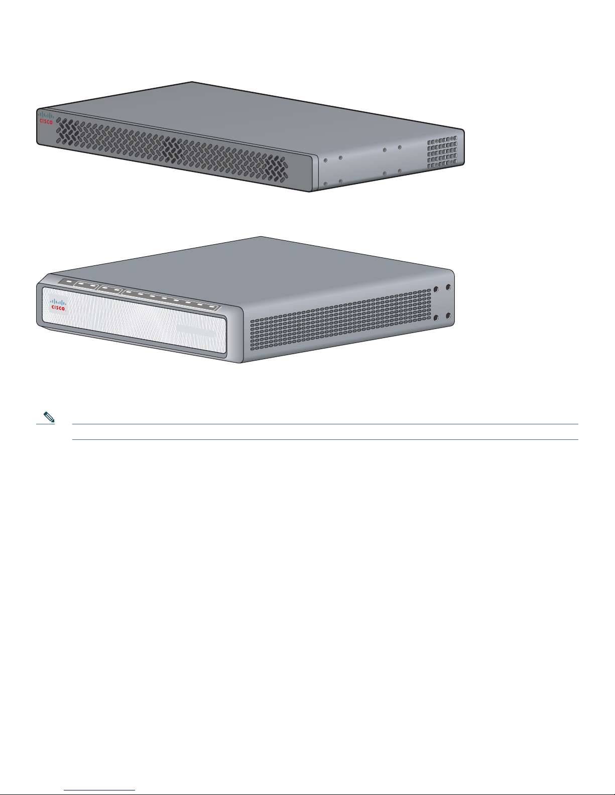
Figure 1 Cisco IAD2430 Series Front Panel (Cisco IAD2432-24FXS IAD shown)
CISCO IAD2400
Figure 2 Cisco IAD2435 IAD Front Panel
OK
FE
0/0
0/1
T1/E1
CD
AL
2/0 2/1
2/2
FXS
2/3 2/4 2/5
2/6 2/7
88839
Cisco IAD2400 SERIES
231872
Figure 3 identifies the different back panels and features of the Cisco IAD2430 series models. Figure 4 shows the back panel
and features of the Cisco IAD2432-24FXS IAD model. Figure 5 shows the back panel and features of the Cisco IAD2435-8FXS
IAD model.
Note Not all models have all functions.
3
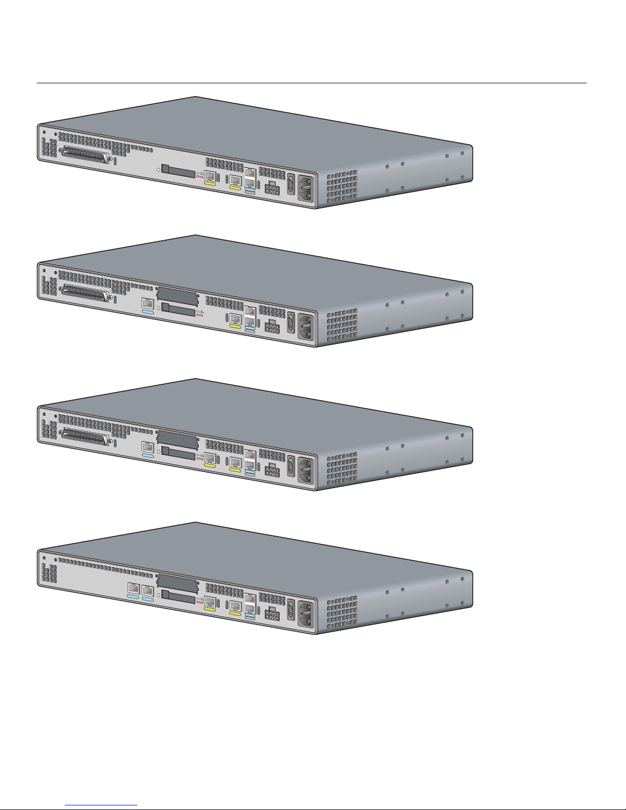
Figure 3 Back Panels for the Cisco IAD2430 Series Models
VG224-24FXS
IAD2431-8FXS
Cisco IAD2430-24FXS IAD
• RJ-21 analog voice
interface
• T1/E1 ports: none
• FE ports: 2
• External flash
memory
88838
Cisco IAD2431-8FXS IAD
• RJ-21 analog voice
interface
• T1/E1 ports: 1
• FE ports: 1
• WIC/VIC option
• External flash
88825
memory
IA
IAD
D
2
2431-1T1
Cisco IAD2431-16FXS IAD
• RJ-21 analog voice
interface
• T1/E1 ports: 1
43
1
-16FXS
• FE ports: 2
• WIC/VIC option
• External flash
88826
memory
Cisco IAD2431-1T1E1 IAD
• T1/E1 ports: 2
• FE ports: 2
• WIC/VIC option
E1
• External flash
memory
88827
4
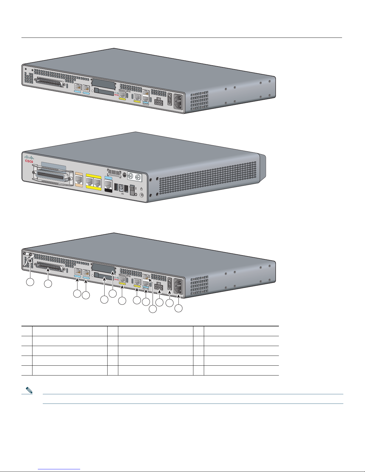
Cisco IAD2432-24FXS IAD
• RJ-21 analog voice
port
• T1/E1 ports: 2
• FE ports: 2
• WIC/VIC option
• External flash
88824
memory
Cisco IAD2435-8FXS IAD
• RJ-21 analog voice
port
F
X
S
WAN
T1/E
1
IAD2435-8FXS
FastEthernet
0
/1
0
/0
CONSOLE
AU
X
12V
DC
SA
• T1/E1 ports: 1
• FE ports: 2
231873
Figure 4 Back Panel Function Options (Cisco IAD2432-24FXS IAD shown)
1
1
4
7
10
13
2
3
4
Chassis ground connection
T1/E1 port 0
Fast Ethernet port 1
Console port
AC power input
6
5
7
RJ-21 connector
2
Flash memory port
5
Fast Ethernet port 0
8
DC power input
11
8
9
11
12
10
13
T1/E1 port 1
3
WIC/VIC slot
6
AUX port
9
On/off switch
12
88828
Note The console port is above the auxiliary port.
5
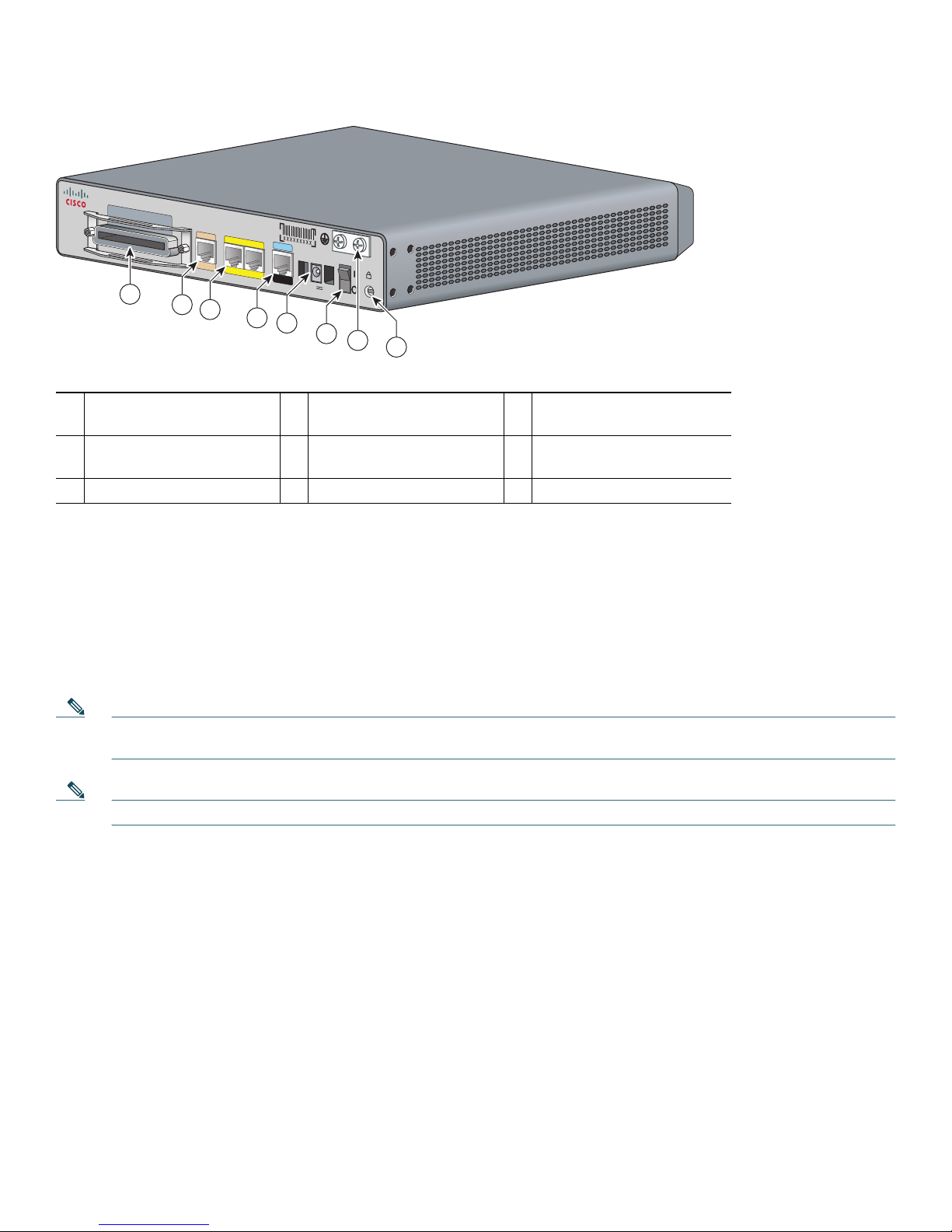
Figure 5 Back Panel Function Options (Cisco IAD2435-8FXS IAD shown)
F
X
S
1
2
WAN
T1/E
1
3
IAD2435-8FXS
FastEthernet
0
/1
0
/0
4
CONSOLE
AU
X
5
12V
D
C
SA
6
7
8
231879
RJ-21 connector
1
Serial port—console or
4
auxiliary
Chassis ground connection
7
T1/E1 WAN uplink
2
Power connector
5
Kensington security slot
8
Fast Ethernet port 1, Fast
3
Ethernet port 0
On/off switch
6
Items Included with Cisco IAD2430, Cisco IAD2431, and Cisco IAD2432 IADs
The following items are included with each Cisco IAD2430, Cisco IAD2431, and Cisco IAD2432 IAD:
• Rack-mount brackets for 19-inch rack; grounding lug and fasteners; power cord
• NEBS grounding kit (Cisco IAD2432-24FXS)
• Connected RJ-45-to-DB9 cable (labeled Console)
• Connected RJ-45-to-DB-25 cable (labeled Auxiliary)
Note The rack-mount brackets for a 19-inch rack, the NEBS grounding kit, and the chassis guard for wall-mounting
applications are not included with the Cisco IAD2435-8FXS IAD.
Note Power cords vary, depending upon local requirements.
Items Included with Cisco IAD2435 IADs
The following items are included with the Cisco IAD2435 IAD:
• Connected RJ-45-to-DB9 cable (labeled Console)
• Power cord
4 Product Serial Number Location
The serial number label for most of the Cisco IAD2430 series routers is located on the bacj of the chassis at the bottom, near
the compliance label. The serial number label for the Cisco IAD2435 integrated access device is located on the bottom of the
chassis. The serial number label is 0.25 x 1 inch (6.35 x 25.4 mm). It has the letters “SN:” followed by eleven characters.
6

5 Accessibility
This product family uses a command-line interface (CLI). Because it is text based and relies on a keyboard for navigation, the
CLI is 508 conformant. All functions of the router can be configured and monitored through the CLI.
To view Cisco accessibility guidelines and product adherence, see Cisco Accessibility Products at the following URL:
http://www.cisco.com/web/about/responsibility/accessibility/products
6 Safety Information
The following warnings apply to the Cisco IAD2430 series IADs and should be read before installing this product.
For safety information that you need to know before working on your Cisco IAD2430 series IAD and for full translations of
the warnings in this document, see the Cisco IAD2400 Series Regulatory Compliance and Safety Information document at the
following URL:
http://www.cisco.com/en/US/docs/routers/access/iad2400/hardware/rcsi/2400rcsi.html
Warning
Warning
Warning
Warning
Warning
IMPORTANT SAFETY INSTRUCTIONS
This warning symbol means danger. You are in a situation that could cause bodily injury. Before you work on any
equipment, be aware of the hazards involved with electrical circuitry and be familiar with standard practices for
preventing accidents. Use the statement number provided at the end of each warning to locate its translation in
the translated safety warnings that accompanied this device.
SAVE THESE INSTRUCTIONS
Only trained and qualified personnel should be allowed to install or replace this equipment.
Do not work on the system, or connect or disconnect cables during periods of lightning activity.
Read the installation instructions before connecting the system to the power source.
This product relies on the building’s installation for short-circuit (overcurrent) protection. Ensure that the
protective device is rated not greater than:
120 VAC, 15A (240 VAC, 10A international)
Statement 1005
Statement 1071
Statement 1030
Statement 1001
Statement 1004
Warning
Warning
Warning
To avoid electric shock, do not connect safety extra-low voltage (SELV) circuits to telephone-network voltage
(TNV) circuits. LAN ports contain SELV circuits, and WAN ports contain TNV circuits. Some LAN and WAN ports
both use RJ-45 connectors. Use caution when connecting cables.
Hazardous network voltages are present in WAN ports regardless of whether power to the unit is OFF or ON. To
avoid electric shock, use caution when working near WAN ports. When detaching cables, detach the end away
from the unit first.
This equipment has been designed for connection to TN and IT power systems.
Statement 1026
Statement 1021
Statement 1007
7

Warning
Warning
Warning
Warning
Before performing any of the following procedures, ensure that power is removed from the DC circuit.
1003
Statement
To prevent accidental discharge in the event of a power line cross, route on-premise wiring away from power
cables and off-premise wiring, or use a grounded shield to separate the on-premise wiring from the power cables
and off-premise wiring. A power line cross is an event, such as a lightning strike, that causes a power surge.
Off-premise wiring is designed to withstand power line crosses. On-premise wiring is protected from power line
crosses by a device that provides overcurrent and overvoltage protection. Nevertheless, if the on-premise wiring
is in close proximity to, or not shielded from, the off-premise wiring or power cables during a lightning strike or
power surge, the on-premise wiring can carry a dangerous discharge to the attached interface, equipment, and
nearby personnel.
Statement 338
For connections outside the building where the equipment is installed, the following ports must be connected
through an approved network termination unit with integral circuit protection.
FXS/T3/E3
Statement 1044
This equipment contains a ring signal generator (ringer), which is a source of hazardous voltage. Do not touch the
RJ-11 (phone) port wires (conductors), the conductors of a cable connected to the RJ-11 port, or the associated
circuit-board when the ringer is active. The ringer is activated by an incoming call.
Statement 1042
Warning
Warning
Warning
Warning
Warning
This equipment needs to be grounded. Use a green and yellow 12 to 14 AWG ground wire to connect the host to
earth ground during normal use.
Statement 242
The importance of proper grounding cannot be overemphasized. It will minimize the potential for damage to your
system and maximize safety at the system site. We recommend you consult a licensed electrician or your local
electric utility company if you have any questions.
Statement 269
A ground wire must always be a single piece of wire. Never splice two wires together for a ground. Corrosion and
weathering can lead to a poor connection at the splice, making the ground ineffective and dangerous.
Statement
270
This unit is intended to be mounted on a wall. Please read the wall mounting instructions carefully before
beginning installation. Failure to use the correct hardware or to follow the correct procedures could result in a
hazardous situation to people and damage to the system.
Statement 248
AC connected units must have a permanent ground connection in addition to the power cable ground wire.
NEBS-compliant grounding satisfies this requirement.
Statement 284
Warning
To prevent bodily injury when mounting or servicing this unit in a rack, you must take special precautions to ensure
that the system remains stable. The following guidelines are provided to ensure your safety:
This unit should be mounted at the bottom of the rack if it is the only unit in the rack.
8

When mounting this unit in a partially filled rack, load the rack from the bottom to the top with the heaviest component at the
bottom of the rack.
Warning
Warning
Warning
Warning
Warning
If the rack is provided with stabilizing devices, install the stabilizers before mounting or servicing the unit in the rack.
Statement 1006
There is the danger of explosion if the battery is replaced incorrectly. Replace the battery only with the same or
equivalent type recommended by the manufacturer. Dispose of used batteries according to the manufacturer’s
instructions.
Take care when connecting units to the supply circuit so that wiring is not overloaded.
Statement 1015
Statement 1018
This unit is intended for installation in restricted access areas. A restricted access area can be accessed only
through the use of a special tool, lock and key, or other means of security.
Statement 1017
This equipment must be grounded. Never defeat the ground conductor or operate the equipment in the absence of
a suitably installed ground conductor. Contact the appropriate electrical inspection authority or an electrician if
you are uncertain that suitable grounding is available.
Use copper conductors only.
Statement 1025
Statement 1024
Warning
Warning
Warning
Warning
Warning
Blank faceplates and cover panels serve three important functions: they prevent exposure to hazardous voltages
and currents inside the chassis; they contain electromagnetic interference (EMI) that might disrupt other
equipment; and they direct the flow of cooling air through the chassis. Do not operate the system unless all cards,
faceplates, front covers, and rear covers are in place.
Statement 1029
Do not use this product near water; for example, near a bath tub, wash bowl, kitchen sink or laundry tub, in a wet
basement, or near a swimming pool.
Never install telephone jacks in wet locations unless the jack is specifically designed for wet locations.
Statement 1035
Statement
1036
Never touch uninsulated telephone wires or terminals unless the telephone line has been disconnected at the
network interface.
Statement 1037
Avoid using a telephone (other than a cordless type) during an electrical storm. There may be a remote risk of
electric shock from lightning.
Statement 1038
Warning
To report a gas leak, do not use a telephone in the vicinity of the leak.
Statement 1039
9

Warning
Warning
Warning
Warning
Warning
Ultimate disposal of this product should be handled according to all national laws and regulations.
Before opening the unit, disconnect the telephone-network cables to avoid contact with telephone-network
voltages.
This equipment must be installed and maintained by service personnel as defined by AS/NZS 3260. Incorrectly
connecting this equipment to a general-purpose outlet could be hazardous. The telecommunications lines must be
disconnected 1) before unplugging the main power connector or 2) while the housing is open, or both.
1043
No user-serviceable parts inside. Do not open.
Installation of the equipment must comply with local and national electrical codes.
Statement 1041
7 Installing the Chassis
This section provides the procedures for installing the chassis.
Statement 1040
Statement
Statement 1073
Statement 1074
Chassis Installation Options
You can set the chassis on a desktop, install it in a rack, or mount it on a wall.
Tip Before proceeding, consider the location of the equipment with respect to a good ground. See the “Grounding the
Chassis” section on page 18.
See the following instructions:
• Using the Correct Bracket Screws, page 10
• Using Rack-Mount Brackets, page 11
• Rack-Mounting the Chassis, page 12
• Setting the Chassis on a Desktop, page 13
• Setting the Cisco IAD2435 on a Desktop, page 13
• Wall-Mounting the Chassis, page 13
• Grounding the Chassis, page 18
• Connecting the RJ-21 Cable in the Velcro Harness, page 23
Caution Use only the mounting hardware supplied with this product.
Using the Correct Bracket Screws
Two sets of bracket attachment screws are provided, in separate packages. Take care to use each screw type, and washers as
needed, in the appropriate locations. Table 1 summarizes the bracket attachment screw types for the Cisco IAD2430,
Cisco IAD2431, and Cisco IAD2432 IADs.
10

Table 1 Bracket Attachment Screws for Rack-Mounting and Wall-Mounting
Rack-Mounting Wall-Mounting
Eight Phillips head screws (four per bracket). Four 6-32 slotted hex screws (two per bracket) and four plastic washers.
Washers are not required. Washers are required.
Using Rack-Mount Brackets
A new bracket accompanies this product. See Figure 6. This rack-mount bracket, with a keyhole feature, facilitates
wall-mounting by allowing the installer to rest the bracket on a starter screw, freeing the installer’s hands.
• To rack-mount the unit, you have three positioning options. See the “Rack-Mounting the Chassis” section on page 12.
• To wall-mount the unit, attach the short leg of the bracket to the chassis at the pair of holes in the center of the chassis side.
See the “Wall-Mounting the Chassis” section on page 13.
Figure 6 Rack-Mount Bracket
88815
Figure 7 shows the rack-mount bracket for the Cisco IAD2435-8FXS model.
Figure 7 Rack-Mount Bracket (Cisco IAD2435-8FXS only)
280933
11
 Loading...