

Page 1

CHAP T E R
1
Overview of Cisco IAD2430 Series IADs
This chapter provides a brief description of Cisco IAD2430 series integrated access devices (IADs) and
contains the following sections:
• Overview, page 1-1
• Physical Description, page 1-6
• LEDs, page 1-7
• Chassis Grounding, page 1-9
• Memory, page 1-9
• Port Numbering Conventions, page 1-9
• Specifications, page 1-10
• Software Elements, page 1-10
• Interfaces and Service Capabilities, page 1-11
• Deployment Options, page 1-13
Overview
OL-4234-06
The Cisco IAD2430 series IADs aggregate multiple channels of data and voice or fax user-side traffic
for transport over single or multiple WAN uplinks. Voice or fax traffic is transported by VoIP or by Voice
over Asynchronous Transfer Mode (VoATM). All platforms support Media Gateway Control Protocol
(MGCP), the signaling protocol H.323, and Session Initiation Protocol (SIP).
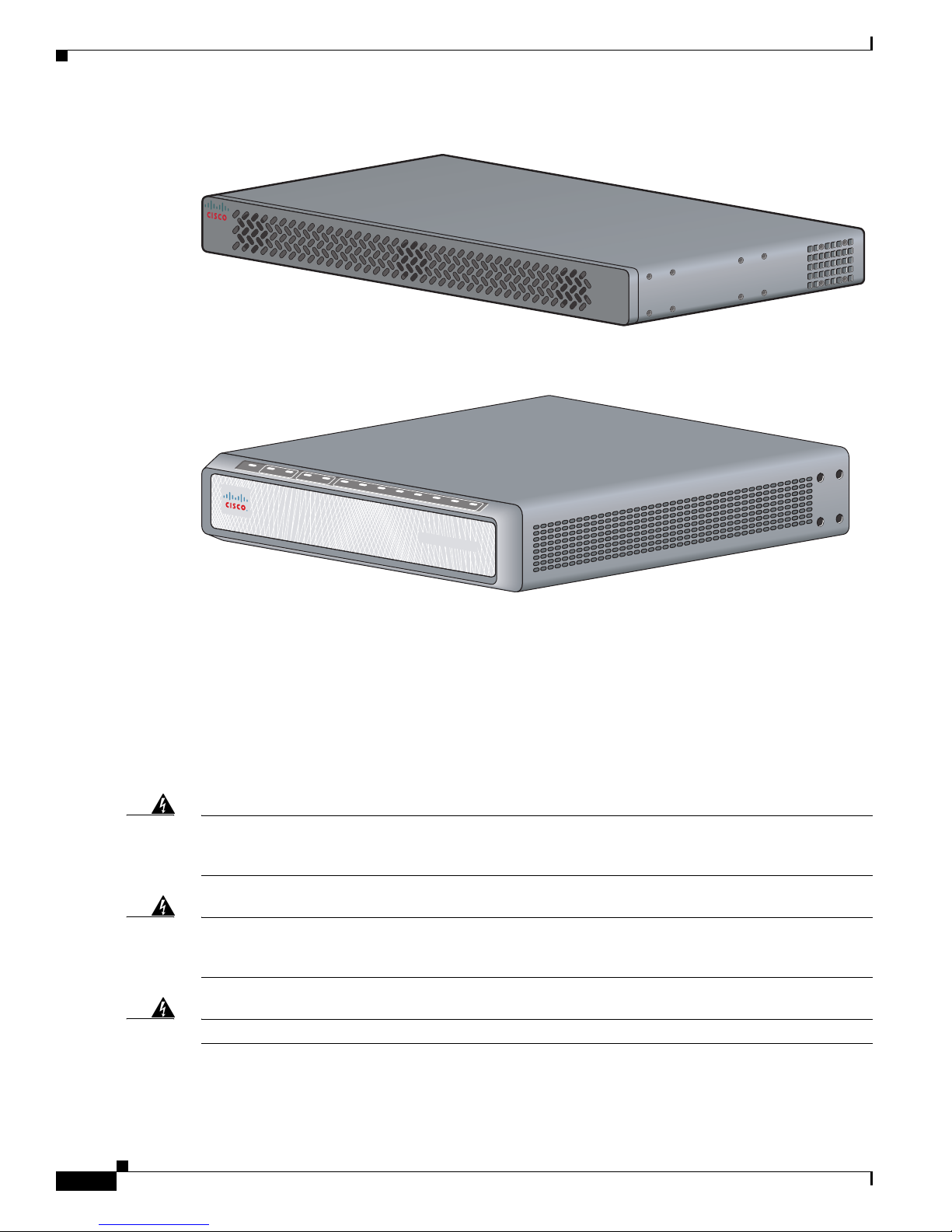
The Cisco IAD2430, Cisco IAD2431, and Cisco IAD2432 series routers consist of five models with a
common front panel (Figure 1). The Cisco IAD2435 series router consists of one model
(Cisco IAD2435-8FXS) with a different front panel (Figure 2). The Cisco IAD2430, Cisco IAD2431,
and Cisco IAD2432 series routers include a slot for the external flash memory card, as well as console,
auxiliary, and flash (CF) memory ports. The front panel, labeled “Cisco IAD2400 Series,” is identical
for all models. However, the back panels, labeled by specific model number, vary considerably,
depending on interfaces, ports, and options. Analog voice ports use an RJ-21 interface.
Cisco IAD2430 Series Integrated Access Devices Hardware Installation Guide
1-1
Page 2
Overview
Figure 1-1 Cisco IAD2430 Series IADs Front Panel
Figure 1-2 Cisco IAD2435 Series IADs Front Panel
OK
FE
0/0
0/1
T1/E1
CD
AL
2/0 2/1
2/2
FXS
2/3 2/4 2/5
2/6 2/7
Chapter 1 Overview of Cisco IAD2430 Series IADs
CISCO IAD2400
88839
Warning
Warning
Cisco IAD2400 SERIES
The Cisco IAD2430 series IADs support the following interfaces:
• 10/100BASE-T LAN connection
• T1/E1 port connections
• RJ-21 analog voice interface
• WAN interface card/voice interface card (WIC/VIC) options
• External/internal flash memory
The Cisco IAD2430 series IADs can be mounted in a rack, on a wall, or a desktop.
There is the danger of explosion if the battery is replaced incorrectly. Replace the battery only with
the same or equivalent type recommended by the manufacturer. Dispose of used batteries according
to the manufacturer’s instructions.
Statement 1015
This unit is intended for installation in restricted access areas. A restricted access area can be
accessed only through the use of a special tool, lock and key, or other means by security.
Statement
1017
231872
Warning
No user-serviceable parts inside. Do not open.
Cisco IAD2430 Series Integrated Access Devices Hardware Installation Guide
1-2
Statement 1073
OL-4234-06
Page 3
Chapter 1 Overview of Cisco IAD2430 Series IADs
Overview
Warning
Ultimate disposal of this product should be handled according to all national laws and regulations.
Statement 1040
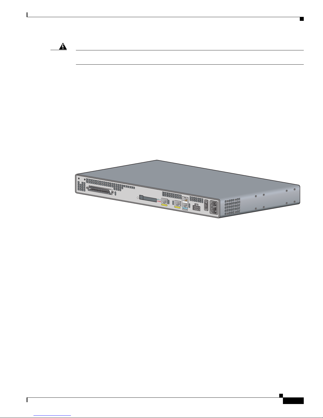
Cisco IAD2430-24FXS IAD
The Cisco IAD2430-24FXS IAD provides 24 analog foreign exchange station (FXS) ports with two
10/100BASE-T ports. The chassis (Figure 1-3) has the following interfaces:
• RJ-21 analog voice interface
• Two 10/100BASE-T ports
• External flash memory slot
• AC and DC power inputs
Figure 1-3 Cisco IAD2430-24FXS Chassis
VG224-24FXS
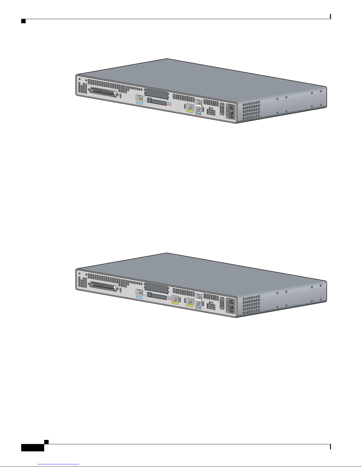
Cisco IAD2431-8FXS IAD
THe Cisco IAD2431-8FXS IAD (Figure 1-4) provides eight analog FXS ports, two 10/100BASE-T
ports, and one T1/E1 WAN port. The chassis has the following interfaces:
• RJ-21 analog voice interface
• One T1/E1 port
• One 10/100BASE-T port
• One WIC/VIC slot
• External flash memory
• AC and DC power inputs
88838
OL-4234-06
Cisco IAD2430 Series Integrated Access Devices Hardware Installation Guide
1-3
Page 4
Overview
Figure 1-4 Cisco IAD2431-8FXS Chassis
Cisco IAD2431-16FXS
The Cisco IAD2431-16FXS IAD (Figure 1-5) provides sixteen analog FXS ports with two
10/100BASE-T ports and two T1/E1 WAN ports. The chassis has the following interfaces:
• RJ-21 analog voice interface
• One T1/E1 port
• Two 10/100BASE-T ports
Chapter 1 Overview of Cisco IAD2430 Series IADs
IAD2431-8FXS
88825
• One WIC/VIC slot
• External flash memory
• AC and DC power inputs
Figure 1-5 Cisco IAD2431-16FXS Chassis
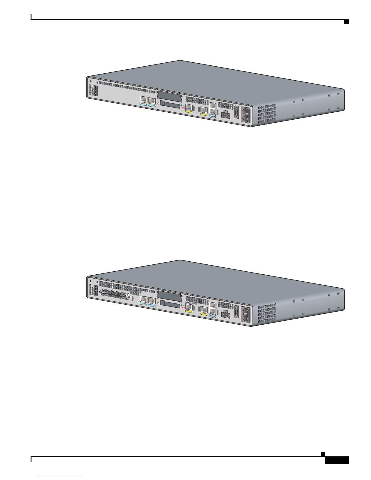
Cisco IAD2431-1T1E1 IAD
The Cisco IAD2431-1T1E1 IAD (Figure 1-6) provides one T1/E1 connection to a PBX, one T1/E1 WAN
port, and two 10/100BASE-T ports. The chassis has the following interfaces:
• Two T1/E1 ports
IA
D
2
4
3
1
-16FXS
88826
• Two 10/100BASE-T ports
• One WIC/VIC slot
• External flash memory
• AC and DC power inputs
Cisco IAD2430 Series Integrated Access Devices Hardware Installation Guide
1-4
OL-4234-06
Page 5
Chapter 1 Overview of Cisco IAD2430 Series IADs
Figure 1-6 Cisco IAD2431-1T1E1 Chassis
Cisco IAD2432-24FXS IAD
The Cisco IAD2432-24FXS IAD (Figure 1-7) provides 24 analog FXS ports, two 10/100BASE-T ports,
and two T1/E1 WAN ports. The chassis has the following interfaces:
• RJ-21 analog voice interface
• Two T1/E1 ports
• Two 10/100BASE-T ports
I
A
D
2431-1T1
Overview
E
1
88827
• One WIC/VIC slot
• External flash memory
• AC and DC power inputs
Figure 1-7 Cisco IAD2432-24FXS Chassis
Cisco IAD2435-8FXS IAD
The Cisco IAD2435-8FXS IAD (Figure 1-8) provides eight analog FXS ports, two Fast Ethernet ports,
and one T1/E1 WAN port. The chassis has the following interfaces:
• RJ-21 analog voice interface
88824
• One T1/E1 port
• Two Fast Ethernet ports
• AC and DC power inputs
OL-4234-06
Cisco IAD2430 Series Integrated Access Devices Hardware Installation Guide
1-5
Page 6

Physical Description
Figure 1-8 Cisco IAD2435-8FXS Chassis
F
X
S
Physical Description
Figure 1-9 and Figure 1-10 show the function options of the two IAD243x chassis. All interface slots are
on the back of the chassis.
WAN
T1/E
1
IAD2435-8FXS
FastEthernet
0
/1
0
/0
CONSOLE
AU
X
Chapter 1 Overview of Cisco IAD2430 Series IADs
12V
D
C
SA
231873
Figure 1-9 Cisco IAD2430 Series IAD Back Panel Function Options
1
2
3
4
6
5
8
7
9
11
12
10
13
1 Chassis ground connection 2 RJ-21 connector 3 T1/E1 port 1
4 T1/E1 port 0 5 Flash memory slot 6 WIC/VIC slot
7 10/100BASE-T port 1 8 10/100BASE-T port 0 9 AUX port
10 Console port 11 DC power input
1
12 On/off switch
13 AC power input
1. This is not a redundant failover power supply connection. You must use either DC or AC.
88828
Cisco IAD2430 Series Integrated Access Devices Hardware Installation Guide
1-6
OL-4234-06
Page 7

Chapter 1 Overview of Cisco IAD2430 Series IADs
Figure 1-10 Cisco IAD2435 Series IAD Back Panel Function Options
F
X
S
1
1 RJ-21 connector 2 T1/E1 WAN uplink 3 Fast Ethernet port 1
4 Serial port—console or
auxiliary
7 Chassis ground connection 8 Kensington security slot
LEDs
IAD2435-8FXS
WAN
FastEthernet
CONSOLE
T1
/E
1
0
/1
0
/0
AU
X
12V
D
C
SA
2
3
4
5
6
7
8
Fast Ethernet port 0
5 Power connector 6 On/off switch
231879
LEDs
Note A Kensington security slot is located on the router back panel. To secure the router to a desktop or other
surface, use the Kensington lockdown equipment.
Note The FE built-in switch ports provide connections to 10/100BASE-T (10/100-Mbps) Fast Ethernet
networks.
The LEDs are located on the back panel of the Cisco IAD2430 series IADs. Figure 1-11 shows LEDs
for the Cisco IAD2430 series IADs. The LEDs for the Cisco IAD2435 series IADs are located on the
front of the chassis. Figure 1-12 shows LEDs for the Cisco IAD2435 series IADs.
OL-4234-06
Cisco IAD2430 Series Integrated Access Devices Hardware Installation Guide
1-7
Page 8

LEDs
Chapter 1 Overview of Cisco IAD2430 Series IADs
Figure 1-11 Cisco IAD2400 Series LEDs (Cisco 2432-24FXS shown)
1
2
3
4
No LED/Color Description
1 ACT—green
Green indicates activity—when any of the 24 voice ports is active
in a call (off hook) or when one of the analog ports is in use
Status—green
Green when accessing IAD
2 CF (Slot 0)—green Green when accessing read or write function
3 Link—green
100—green
FDX—green
4 ACT—green
SYS—green
PWR—green
Figure 1-12 Cisco IAD2435 Series LEDs
1
Indicates link activity
100BASE-T is active
Green when full duplex is active, off when in half-duplex mode
Blinking green during packet transfer and interrupts
Blinking green for power-on and self-test, then solid green
Solid green when system has power
2 3
4
95007
OK
F
E
0
/
0
0
/
1
T
1
/
E
1
CD
A
Cisco IAD2430 Series Integrated Access Devices Hardware Installation Guide
1-8
FE
0/0
OK
L
2/
02/
1
2/
22/
F
3
T1/E1
0/1
X
S
2/
42/
5
2/
6
Cisco IAD2400 SERIES
2/0 2/1
ALCD
2/
7
2/2
FXS
2/3 2/4 2/5
2/6 2/7
272227
OL-4234-06
Page 9

Chapter 1 Overview of Cisco IAD2430 Series IADs
No LED/Color LED Color and Description
1 PWR
OK—green
2 FE ports
0/1—green
3 T1/E1 (carrier
detect)—green
T1/E1
AL—Amber
4 FXS ports 0
through
7—green
Chassis Grounding
Off—no power
Steady on—normal operation
Slow blink—boot up phase or in ROMMON monitor mode
Off—No link
Steady on—link
Blinking—TXD/RXD data
Off—no Carrier Detect
Steady on—Carrier Detect
Off—no Alarm condition
Steady on—Alarm condition
Off—On hook
Steady On—Off hook
Chassis Grounding
Chassis grounding is provided through the power cable, which uses a standard grounding plug. The
chassis is also equipped with two 4 x 0.7 screw terminals for chassis grounding. The accessory kit
contains a crimp-type ground lug that attaches to the two screw terminals. For more information, see the
“Installing the Ground Connection” section on page 3-14.
Memory
The Cisco IAD2430 series routers contain flash memory and main memory.
Onboard flash memory contains the Cisco IOS software image, boot flash contains the ROMMON boot
code, and counterfeit prevention contains the cookie configuration.
The default flash memory for the Cisco IAD2430 series IADs is 128 MB. Onboard CPU memory is
256 MB.
Port Numbering Conventions
Port numbering conventions for Cisco IAD2430, IAD2431, and IAD2432 series IADs are as follows:
• An external flash memory card is numbered CF 0.
• The 10/100BASE-T ports are numbered 10/100BASE-T 0/0 and 10/100BASE-T 0/1, from right to
left.
• The T1/E1 ports are numbered T1 1/0 or E1 1/0 and T1 1/1 or E1 1/1, from right to left.
• The slot for WICs and VICs is numbered slot 0. WIC and VIC interfaces are numbered by interface
with this slot number and an interface number, beginning with 0 and numbered from right to left.
• FXS voice port numbering begins at 2/0 and extends to 2/7, 2/15, or 2/23, depending on the number
of voice ports.
OL-4234-06
Cisco IAD2430 Series Integrated Access Devices Hardware Installation Guide
1-9
Page 10

Specifications
Port numbering conventions for the Cisco IAD2435 series IAD are as follows:
• Fast Ethernet ports are numbered 0 and 1, from left to right.
• The controller T1/E1 port is numbered T1 0 or E1 0, from left to right.
• FXS voice port numbering begins at 0 and reaches a maximum of 7, depending on the number of
voice ports, from left to right.
Specifications
For the Cisco IAD2430 series hardware and electrical speicfications, see the Cisco IAD2430 series data
sheets at the following URL:
http://www.cisco.com/en/US/prod/collateral/voicesw/ps6790/gatecont/ps887/ps5321/product_data_she
et09186a008019aded.html
Software Elements
Chapter 1 Overview of Cisco IAD2430 Series IADs
The operating system for the Cisco IAD2430 series IADs is the Cisco IOS software that resides in flash
memory.
Software Images
Images c2430-is-mz and c2430-ik9o3s-mz can be loaded on the following platforms which have T1E1
and VWIC ports:
• IAD2431-8FXS
• IAD2431-16FXS
• IAD2431-1T1E1
• IAD2432-24FXS
Images c2430-i6s-mz and c2430-i6k9o3s-mz should be loaded on the IAD2430-24FXS, which does not
have a VWIC slot.
Configuration Connections
You can use an ASCII terminal or a PC to configure a Cisco IAD2430 series IAD. The configuration can
be performed in several ways:
• Locally, with a direct connection through the serial port
• Remotely, with a connection through the serial port and a modem
• Through Telnet and TFTP
Cisco IAD2430 Series Integrated Access Devices Hardware Installation Guide
1-10
OL-4234-06
Page 11

Chapter 1 Overview of Cisco IAD2430 Series IADs
Configuration Methods
You can configure a Cisco IAD2430 series IAD automatically using the Simple Network-Enabled
Auto-Provision (SNAP) option, or you can configure theCisco IAD2430 series IAD manually using
several methods listed in “Manual Configuration” section on page 1-11.
Automated Configuration
If your Cisco IAD2430 series IAD was ordered with the SNAP option, no on-site configuration is
required. When the Cisco IAD is powered on and connected to the WAN, the SNAP application
downloads the applicable configuration files automatically. For additional information about SNAP, see
the following URL:
http://www.cisco.com/univercd/cc/td/doc/product/software/ios122/122newft/122t/122t8/ftapiad8.htm
Note The SNAP option is not available on the Cisco IAD2435 IAD.
Interfaces and Service Capabilities
Manual Configuration
When you install a Cisco IAD2430 series IAD, see the “Power-On Procedure” section on page 4-1 for
the initial configuration. This configuration sets the basic communication parameters. After the Cisco
IAD is operating and able to communicate, use the procedures in the Cisco IAD2430 Series Software
Configuration Guide to configure the specific services and functions, or to make changes to the existing
configuration.
You can use any of several manual methods for configuring a Cisco IAD2430 series IAD:
• System configuration dialog
• Configuration mode—Cisco IOS software command-line interface (CLI)
• setup command facility—Remote configuration through a LAN or WAN
• SNMP-based application—CiscoView or HP OpenView
• HTTP-based configuration server—Provides access to the CLI from a web browser
Interfaces and Service Capabilities
Table 1-1 describes the various physical ports and the services that each port type supports, including
the following.
• Two administrative ports—One console and one auxiliary.
Note The Cisco IAD2435 IAD provides a connection to the terminal or PC for software
configuration or troubleshooting. The console port may be configured as a virtual auxiliary
port for dial backup and remote management.
• One or two 10/100BASE-T LAN ports.
• One or two Fast Ethernet ports.
OL-4234-06
Cisco IAD2430 Series Integrated Access Devices Hardware Installation Guide
1-11
Page 12

Chapter 1 Overview of Cisco IAD2430 Series IADs
Interfaces and Service Capabilities
• The Cisco IAD2431 and Cisco IAD2432 IADs for a T1/E1 WAN interface are equipped with one or
two T1/E1 WAN ports.
• Cisco IAD2430 series IADs for an analog voice user interface are equipped with an RJ-21 port for
connection to a distribution panel.
• Cisco IAD2432 IADs for adigital voice user interface are equipped with a T1/E1 port for connection
to a PBX.
Caution All Cisco IAD2430 series IADs are customer premises equipment (CPE) only.
Table 1-1 Cisco IAD2430 Series Interfaces and Service Capabilities
Port Interface Configurations Interface To Services Supported Details
Console
port 0/0
Auxiliary
port 0/1
Fast Ethernet
ports 0/0, 0/1
RJ-21—8,
16, or 24
analog FXS
voice ports
Ports 2/0 to
2/23
Ports 0 to 7
(IAD2435
only)
T1/E1 trunk
ports 0,1
EIA/TIA-232 asynchronous
serial (DCE)
EIA/TIA-232 asynchronous
serial (DTE)
ASCII terminal
Personal computer
Local administrative
access
Modem Remote administrative
access
RJ-45 physical interface
Note The serial port on the
RJ-45 physical interface
Note The serial port on the
Data backup
10/100BASE-T (802.3) LAN Data RJ-45 physical interface
FXS (loop-start or
ground-start)
Analog phone, fax,
or modem
Network side of key
system
Network side of
analog PBX
Channelized T1/E1 WAN
Carrier network
Analog voice/fax or
modem
Service types:
• AT M
• Cisco HDLC
• PPP
1
Transport types:
• TDM
• Leased lines
2
trunk
Provides battery
RJ-21 physical interface
8-port FXS, on premise only
16-port FXS, on premise only
24-port FXS, on premise only
Built-in CSU/DSU
T1.403-compliant
RJ-48C/CA81A physical
interface
Supports as many as 24 DS0s
Cisco IAD2435 acts
as either console or
auxiliary.
Cisco IAD2435 acts
as either console or
auxiliary.
3
Cisco IAD2430 Series Integrated Access Devices Hardware Installation Guide
1-12
OL-4234-06
Page 13

Chapter 1 Overview of Cisco IAD2430 Series IADs
Table 1-1 Cisco IAD2430 Series Interfaces and Service Capabilities (continued)
Port Interface Configurations Interface To Services Supported Details
WIC/VIC
slot
S0 (serial)
4
CF
Slot 0 Flash memory Flash memory card
1. HDLC = High-Level Data Link Control
2. TDM = time-division multiplexing
3. CSU/DSU = channel service unit/data service unit
4. CF = Flash memory
HDLC-based data WAN
Carrier network
User equipment
Cisco HDLC
PPP
VoIP over PPP
Physical interfaces:
• EIA/TIA-232
• EIA/TIA-530/530A
• EIA/TIA-449
• V. 3 5
• X.21
Deployment Options
Configuration Options
The following interface options are available in Cisco IAD2430 series IADs:
Table 1-2 Configuration Options
Cisco IAD2430 Series RJ-21
IAD2430-24FXS Yes None 2 N/A External
IAD2431-8FXS Yes 1 1 Yes External
IAD2431-16FXS Yes 1 2 Yes External
IAD2431-1T1E1 No 2 2 Yes External
IAD2432-24FXS Yes 2 2 Yes External
IAD2435-8FXS Yes 1 2 N/A N/A
1. Analog voice interface.
2. T1/E1 ports.
3. 10/100BASE-T ports.
4. WAN interface card (data); voice interface card (voice).
5. Flash (CF) memory.
Deployment Options
1
T1/E1
2
FE
3
WIC/VIC
4
5
CF
Figure 1-13 through Figure 1-16 show some typical deployment scenarios for the Cisco IAD2430 series
integrated access devices (IADs).
OL-4234-06
Cisco IAD2430 Series Integrated Access Devices Hardware Installation Guide
1-13
Page 14

Deployment Options
Chapter 1 Overview of Cisco IAD2430 Series IADs
Figure 1-13 Analog FXS User Interfaces with Metro Ethernet WAN Interface
Ethernet
RJ-21
IAD
Cisco IAD model number:
IAD2430-24FXS
Distribution
panel
Figure 1-14 T1/E1 WAN Interface with Analog FXS User Interfaces
Ethernet
Analog
telephones
88997
WAN
T1 RJ-21
IAD
Cisco IAD model number:
IAD2431-8FXS
IAD2431-16FXS
IAD2432-24FXS
IAD2435-8FXS
Distribution
panel
Figure 1-15 WAN Interface with Analog FXS and FXO User Interfaces
Ethernet
WAN
T1 Multiple FXS and FXO
IAD
Cisco IAD model number:
Cisco IAD2432-24FXS
with
Cisco VIC2-4FXO interface card
Distribution
panel
Analog
telephones
88998
Analog
telephones
24 FXS
voice ports
PBX
4 FXO
voice ports
PBX
88996
Cisco IAD2430 Series Integrated Access Devices Hardware Installation Guide
1-14
OL-4234-06
Page 15

Chapter 1 Overview of Cisco IAD2430 Series IADs
Figure 1-16 T1/E1 with T1/E1 Interface to PBX
Deployment Options
Ethernet
WAN
T1 T1
Cisco IAD model number:
IAD2431-1T1E1
IAD
PBX
88995
OL-4234-06
Cisco IAD2430 Series Integrated Access Devices Hardware Installation Guide
1-15
Page 16

Deployment Options
Chapter 1 Overview of Cisco IAD2430 Series IADs
Cisco IAD2430 Series Integrated Access Devices Hardware Installation Guide
1-16
OL-4234-06
 Loading...