

Page 1

Overview
CHA PTER
1
Overview of Cisco IAD2430 Series IADs
This chapter provides a brief description of Cisco IAD2430 series integrated access devices and contains
the following sections:
• Overview, page 1-1
• Cisco IAD2430 Series Deployment, page 1-6
• Interfaces and Service Capabilities, page 1-7
• Physical Description and LEDs, page 1-9
• Specifications, page 1-11
• Software Elements, page 1-12
Warning
The Cisco IAD2430 series integrated access devices (IADs) aggregate multiple channels of data and
voice or fax user-side traffic for transport over single or multiple wide-area network (WAN) uplinks.
Voice or fax traffic is transported by Voice over Internet Protocol (VoIP) or by Voice over Asynchronous
Transfer Mode (VoATM). All platforms support Media Gateway Control Protocol (MGCP), the signaling
protocol H.323, and Session Initiation Protocol (SIP).
Cisco IAD2430 series IADs support the following interfaces:
• 10/100BASE-T LAN connection
• T1/E1 port connections
• RJ-21 analog voice interface
• WIC/VIC options
• External/Internal compact flash
Cisco IAD2430 series IADs can be housed in a rack, mounted on a wall, or set on a benchtop surface.
This unit is intended for installation in restricted access areas. A restricted access area can be
accessed only through the use of a special tool, lock and key, or other means by security.
1017
Statement
OL-4234-05
Cisco IAD2430 Series Integrated Access Devices Hardware Installation Guide
1-1
Page 2
Overview
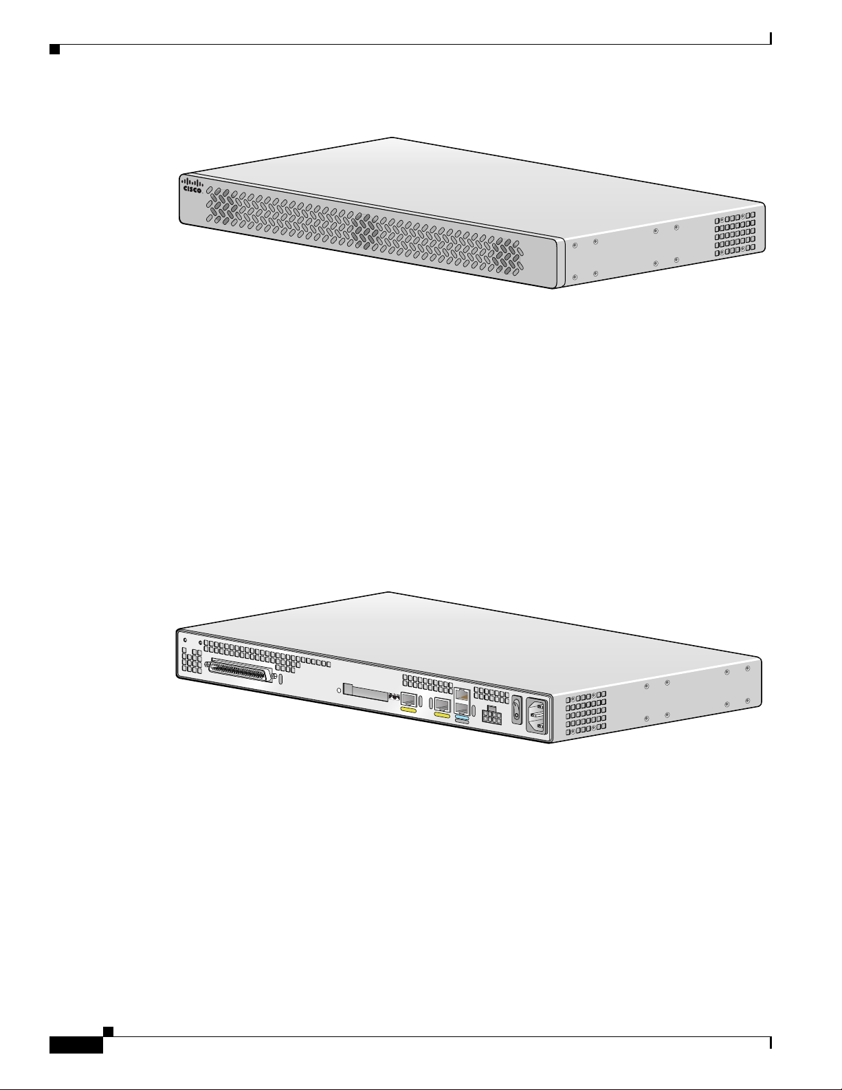
Figure 1-1 Cisco IAD2430 Series IADs Front Panel
Figure 1-2 through Figure 1-6 show the basic types of Cisco IAD2430 series chassis as seen from the
cabling side.
Cisco IAD2430-24FXS
The Cisco IAD2430-24FXS provides 24 analog foreign exchange station (FXS) ports with two
10/100BASE-T ports. The chassis has the following interfaces:
Chapter 1 Overview of Cisco IAD2430 Series IADs
CISCO IAD2400
88839
• RJ-21 analog voice interface
• Two 10/100BASE-T ports
• External compact flash memory
• AC and DC power inputs
Figure 1-2 Cisco IAD2430-24FXS Chassis
VG224-24FXS
88838
1-2
Cisco IAD2430 Series Integrated Access Devices Hardware Installation Guide
OL-4234-05
Page 3
Chapter 1 Overview of Cisco IAD2430 Series IADs
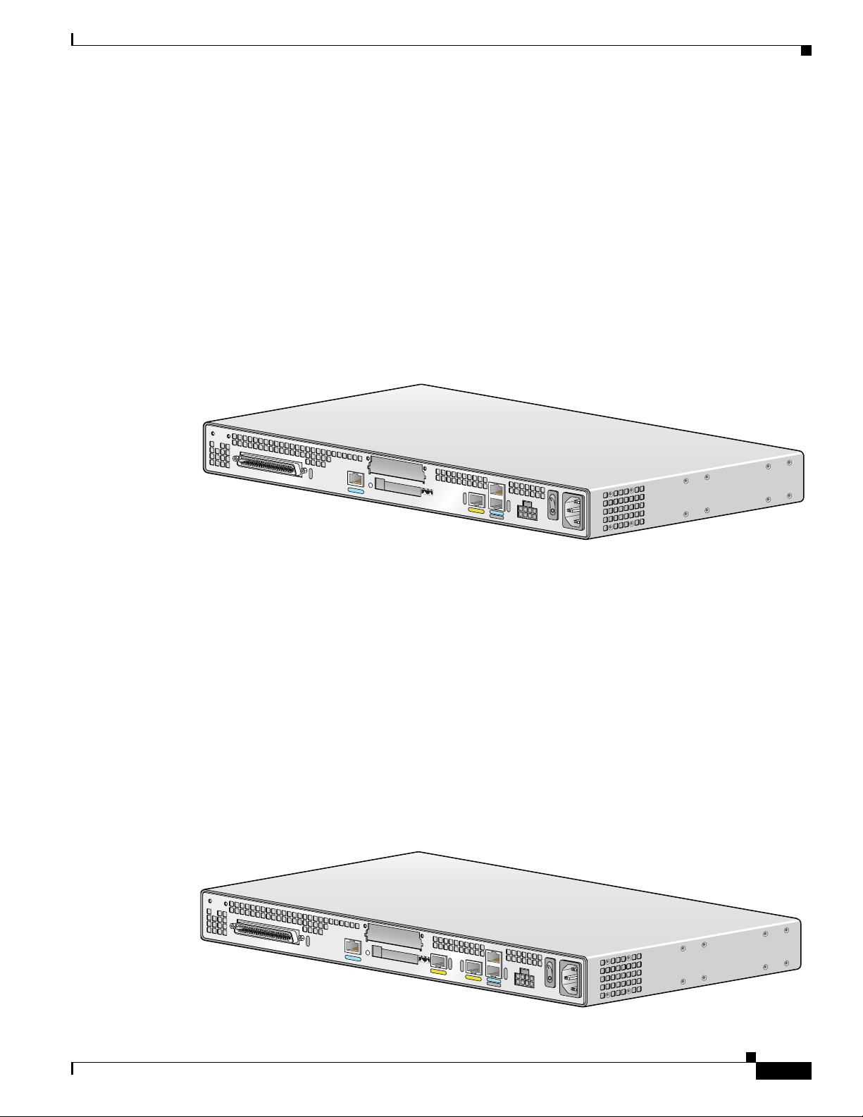
Cisco IAD2431-8FXS
THe Cisco IAD2431-8FXS provides eight analog FXS ports, two 10/100BASE-T ports, and one T1/E1
WAN port. The chassis has the following interfaces:
• RJ-21 analog voice interface
• One T1/E1 port
• One 10/100BASE-T port
• One WIC/VIC slot
• External compact flash memory
• AC and DC power inputs
Figure 1-3 Cisco IAD2431-8FXS Chassis
Overview
Cisco IAD2431-16FXS
The Cisco IAD2431-16FXS provides sixteen analog FXS ports with two 10/100BASE-T ports and two
T1/E1 WAN ports. The chassis has the following interfaces:
• RJ-21 analog voice interface
• One T1/E1 port
• Two 10/100BASE-T ports
• One WIC/VIC slot
• External compact flash memory
• AC and DC power inputs
Figure 1-4 Cisco IAD2431 -16FXS
IAD2431-8FXS
88825
OL-4234-05
IAD2431-16FXS
88826
Cisco IAD2430 Series Integrated Access Devices Hardware Installation Guide
1-3
Page 4
Overview
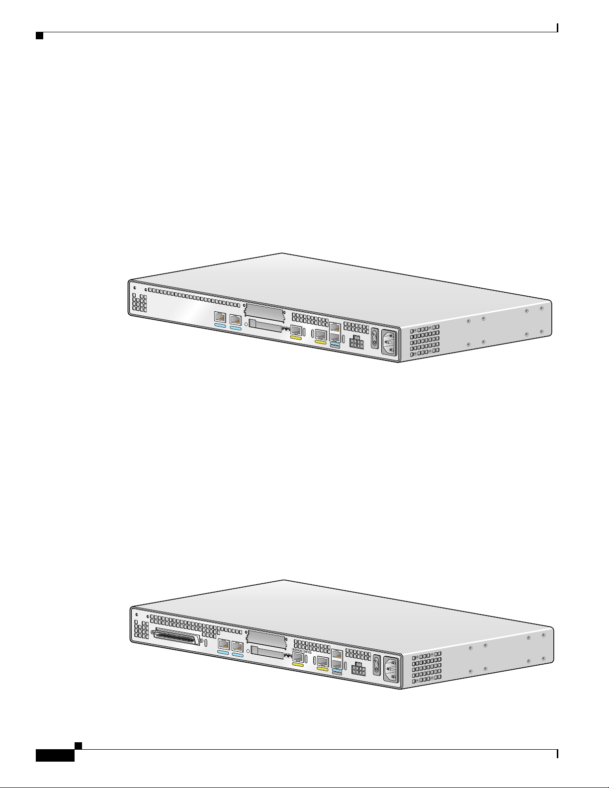
Cisco IAD2431-1T1E1
The Cisco IAD2431-1T1E1 provides one T1/E1 connection to a PBX, one T1/E1 WAN port, and two
10/100BASE-T ports. The chassis has the following interfaces:
• Two T1/E1 ports
• Two 10/100BASE-T ports
• One WIC/VIC slot
• External compact flash memory
• AC and DC power inputs
Figure 1-5 Cisco IAD2431-1T1E1
Chapter 1 Overview of Cisco IAD2430 Series IADs
Cisco IAD2432-24FXS
The Cisco IAD2432-24FXS provides 24 analog FXS ports, two 10/100BASE-T ports, and two T1/E1
WAN ports. The chassis has the following interfaces:
• RJ-21 analog voice interface
• Two T1/E1 ports
• Two 10/100BASE-T ports
• One WIC/VIC slot
• External compact flash memory
• AC and DC power inputs
Figure 1-6 Cisco IAD2432-24FXS
IAD2431-1T1E1
88827
1-4
88824
Cisco IAD2430 Series Integrated Access Devices Hardware Installation Guide
OL-4234-05
Page 5

Chapter 1 Overview of Cisco IAD2430 Series IADs
Product Serial Number Location for the Cisco IAD2430 Series IADs
The serial number label for the Cisco IAD2430 Series IADs is located on the rear of the chassis, in the
middle-left side. (See Figure 1-14.)
Figure 1-7 Serial Number Locations
AAANNNNX
XXX
IAD2431-8FXS
Overview
Note The serial number for the Cisco IAD2430 Series IADs is 11 characters long.
Configuration Options
The following interface options are available in Cisco IAD2430 series IADs:
Table 1-1 Configuration Options
Cisco IAD2430 Series RJ-21
IAD2430-24FXS yes none 2 n/a external
IAD2431-8FXS yes 1 1 yes external
IAD2431-16FXS yes 1 2 yes external
IAD2431-1T1E1 no 2 2 yes external
IAD2432-24FXS yes 2 2 yes external
1. Analog voice interface
2. T1/E1 ports
3. 10/100BASE-T ports
4. WAN interface card (data); voice interface card (voice)
5. Compact flash
AAANNNNXXXX
103054
1
T1/E1
2
FE
3
WIC/VIC
4
5
CF
OL-4234-05
Cisco IAD2430 Series Integrated Access Devices Hardware Installation Guide
1-5
Page 6

Cisco IAD2430 Series Deployment
Cisco IAD2430 Series Deployment
Figure 1-8 through Figure 1-11 show some typical deployment scenarios for Cisco IAD2430 series
integrated access devices.
Figure 1-8 Analog FXS User Interfaces with Metro Ethernet WAN Interface
Ethernet
RJ-21
IAD
Cisco IAD model number:
IAD2430-24FXS
Distribution
panel
Chapter 1 Overview of Cisco IAD2430 Series IADs
Analog
telephones
88997
Figure 1-9 T1/E1 WAN Interface with Analog FXS User Interfaces
Ethernet
WAN
Cisco IAD model number:
IAD2431-8FXS
IAD2431-16FXS
IAD2432-24FXS
T1 RJ-21
IAD
Distribution
panel
Analog
telephones
88998
1-6
Cisco IAD2430 Series Integrated Access Devices Hardware Installation Guide
OL-4234-05
Page 7

Chapter 1 Overview of Cisco IAD2430 Series IADs
Figure 1-10 WAN Interface with Analog FXS and FXO User Interfaces
Interfaces and Service Capabilities
Ethernet
WAN
Cisco IAD model number:
Cisco IAD2432-24FXS
with
Cisco VIC2-4FXO interface card
Figure 1-11 T1/E1 with T1/E1 Interface to PBX
WAN
T1 Multiple FXS and FXO
IAD
Ethernet
T1 T1
IAD
Analog
telephones
24 FXS
voice ports
PBX
4 FXO
voice ports
PBX
Distribution
panel
88996
PBX
Cisco IAD model number:
IAD2431-1T1E1
Interfaces and Service Capabilities
The various physical ports and the services supported by each port type are described in Ta ble 1-2.
• Two administrative ports—One console and one auxiliary.
• One or two 10/100BASE-T LAN ports.
• The Cisco IAD2431 and Cisco IAD2432 IADs for T1/E1 WAN interface are equipped with one or
two T1/E1 WAN ports.
• Cisco IAD2430 series IADs for analog voice user interface are equipped with an RJ-21 port for
connection to a distribution panel.
• Cisco IAD2432 IADs for digital voice user interface are equipped with a T1/E1 port for connection
to a PBX.
Caution All Cisco 2430 series IADs are customer premises equipment (CPE) only.
88995
OL-4234-05
Cisco IAD2430 Series Integrated Access Devices Hardware Installation Guide
1-7
Page 8

Chapter 1 Overview of Cisco IAD2430 Series IADs
Interfaces and Service Capabilities
Table 1-2 Cisco IAD2430 Series Interfaces and Service Capabilities
Port Interface Configurations Interface To Services Supported Details
Console
Port 0/0
Auxiliary
Port 0/1
EIA/TIA-232 asynchronous
serial (DCE
1
)
EIA/TIA-232 asynchronous
serial (DTE
2
)
ASCII terminal
Personal computer
Local administrative
access
Modem Remote administrative
access
RJ-45 physical interface
RJ-45 physical interface
Data backup
Fast Ethernet
10/100BASE-T (802.3) LAN Data RJ-45 physical interface
Port 0/0, 0/1
RJ-21
8, 16, or 24
analog FXS
voice ports
Port 2/0 to
2/23
T1/E1 trunk
Port 0,1
WIC/VIC
slot
S0 (serial)
FXS (loop-start or
ground-start)
Analog phone, fax,
or modem
Network side of key
system
Network side of
analog PBX
Channelized T1/E1 WAN
Carrier network
HDLC-based data WAN
Carrier network
User equipment
Analog voice/fax or
modem
Service types:
• AT M
• Cisco HDLC
• PPP
3
3
Transport types:
• TDM
• Leased lines
4
trunk
Cisco HDLC
6
PPP
VoIP over PPP
Provides battery
RJ-21 physical interface
8-port FXS, on premise only
16-port FXS, on premise only
24-port FXS, on premise only
Built-in CSU/DSU
T1.403-compliant
RJ-48C/CA81A physical
interface
Supports as many as 24 DS0s
Physical interfaces:
• EIA/TIA-232
• EIA/TIA-530/530A
5
7
CF
Slot 0
1. DCE = data communications equipment
2. DTE = data terminal equipment
3. HDLC = High-Level Data Link Control
4. TDM = time-division multiplexing
5. CSU/DSU = channel service unit/data service unit
6. PPP = Point-to-Point Protocol
7. CF = compact flash memory
Cisco IAD2430 Series Integrated Access Devices Hardware Installation Guide
1-8
• EIA/TIA-449
• V. 3 5
• X.21
Flash memory Compact flash card
OL-4234-05
Page 9

Chapter 1 Overview of Cisco IAD2430 Series IADs
Physical Description and LEDs
All interface slots and LEDs are on the rear of the chassis.
Figure 1-12 Cisco IAD2430 Series IAD
Physical Description and LEDs
1
2
3
4
6
5
8
7
9
11
12
10
13
1 Chassis ground connection 6 WIC/VIC slot 11 DC power input
2 RJ-21 connector 7 10/100BASE-T port 1 12 On/off switch
3 T1/E1 port 1 8 10/100BASE-T port 0 13 AC power input
4 T1/E1 port 0 9 AU X port
5 Compact flash slot 10 Console port
1. This is not a redundant failover power supply connection. You must use either DC or AC.
Figure 1-13 Cisco IAD2400 Series LEDs
88828
1
OL-4234-05
1
Table 1-3 Cisco 2430 Series IAD LEDs (Cisco 2432-24FXS shown)
2
3
4
No LED/Color Description
1 ACT—green
Green indicates activity; when any of the 24 voice ports is active in
a call (off hook) or one of the analog ports is in use
Status—green
Green when accessing IAD
2 CF (Slot 0)—green Green when accessing read or write function
Cisco IAD2430 Series Integrated Access Devices Hardware Installation Guide
95007
1-9
Page 10

Physical Description and LEDs
Table 1-3 Cisco 2430 Series IAD LEDs (Cisco 2432-24FXS shown)
No LED/Color Description
3 Link—green
Chapter 1 Overview of Cisco IAD2430 Series IADs
Indicates link activity
100—green
FDX—green
4 ACT—green
SYS—green
PWR—green
100BASE-T active
Green when full duplex active, off when in half-duplex mode
Blinking green during packet transfer and interrupts
Blinking green for power on and self-test, solid green thereafter
Solid green when system has power
Product Serial Number Location for Cisco IAD2430 Series IADs
The serial number label for the Cisco IAD2430 Series IADs is located on the rear of the chassis, in the
middle-left side. (See Figure 1-14.)
Figure 1-14 Serial Number Locations
AAANNNNXXXX
AAANNNNXXXX
IAD2431-8FXS
103054
Note The serial number for Cisco IAD2430 Series IADs is 11 characters long
Chassis Grounding
Chassis grounding is provided through the power cable, which uses a standard grounding plug. The
chassis is also equipped with two multi 4 x 0.7 screw terminals for chassis grounding. The accessory kit
contains a crimp-type ground lug that attaches to the two screw terminals. For more information, refer
to the “Installing the Ground Connection” section on page 3-11.
Port Numbering Conventions
Port numbering conventions for Cisco IAD2430 series IAD are as follows:
• An external compact flash card is numbered CF 0.
• 10/100BASE-T ports are numbered 10/100BASE-T 0/0 and 10/100BASE-T 0/1 from right to left.
• T1/E1 ports are numbered T1 or E1 1/0 and T1 or E1 1/1 from right to left.
Cisco IAD2430 Series Integrated Access Devices Hardware Installation Guide
1-10
OL-4234-05
Page 11

Chapter 1 Overview of Cisco IAD2430 Series IADs
• The slot for WICs and VICs is numbered slot 0. WIC and VIC interfaces are numbered by interface
with this slot number and an interface number, beginning with 0 and running from right to left.
• FXS voice port numbering begins at 2/0 and extends to 2/7, 2/15, or 2/23, depending on the number
of voice ports.
Specifications
Table 1-4 Cisco IAD2430 Series IAD Technical Specifications
Characteristic Value
Dimensions 1.75H x 17.5W x 13.5D in. (44.4 x 444.5 x 342.9 mm)
Weight 11 lb (4.106 kg) max
Input power 100 to 240 VAC, 1 A (max), 50 to 60 Hz, 70 W (max)
Maximum power surge
Input power
(DC 12-volt battery) by chassis
• Cisco IAD2430-24FXS—60 W (204.7 BTU/h)
• Cisco IAD2431-8FXS—50 W (170.6 BTU/h)
• Cisco IAD2431-16FXS—60 W (204.7 BTU/h)
Specifications
• Cisco IAD2432-24FXS—70 W (238.8 BTU/h)
• Cisco IAD2431-1T1E1—35 W (119.4 BTU/h)
Caution Do not try to use AC and DC power at the same time. If you do, the unit stops
operating and you have to reboot using a single power source.
MTBF
• Cisco IAD2430-24FXS—195,671 hours
• Cisco IAD2431-8FXS—121,434 hours
• Cisco IAD2431-16FXS—112,421 hours
• Cisco IAD2432-24FXS—103,628 hours
• Cisco IAD2431-1T1E1—126,118 hours
Operating environment 32 to 122°F (0 to 50°C)
Nonoperating temperature –40 to 185°F (–40 to 85°C)
Operating humidity 5 to 95%, noncondensing
Noise level 55 dB @ 3 ft
Agency approvals Refer to the Cisco IAD2400 Series Regulatory Compliance and Safety Information
document that accompanied your device for agency approvals.
OL-4234-05
Warning
Ultimate disposal of this product should be handled according to all national laws and regulations.
Statement 1040
Cisco IAD2430 Series Integrated Access Devices Hardware Installation Guide
1-11
Page 12

Software Elements
Software Elements
The operating system for Cisco IAD2430 series IADs is the Cisco IOS software that resides in flash
memory.
Configuration Connections
You can use an ASCII terminal or a PC to configure a Cisco IAD2430 series IAD. The configuration can
be performed in several ways:
• Locally, with a direct connection through the console port
• Remotely, with a connection through the auxiliary port and a modem
• Through Telnet and TFTP
Configuration Methods
Chapter 1 Overview of Cisco IAD2430 Series IADs
Automated Configuration
If your Cisco IAD2430 series IAD was ordered with the Simple Network-Enabled Auto-Provision
(SNAP) option, no on-site configuration is required. When the Cisco IAD is powered on and connected
to the WAN, the SNAP application downloads the applicable configuration files automatically. For
additional information about SNAP, refer to the Simple Network-Enabled Auto-Provisioning for
Cisco 2420 Series IAD feature module at the following URL:
http://www.cisco.com/univercd/cc/td/doc/product/software/ios122/122newft/122t/122t8/ftapiad8.htm
Manual Configuration
When a Cisco IAD2430 series IAD is first installed, use the procedure in
Chapter 4, “Powering On Cisco IAD2430 Series IADs,” for the initial configuration. This sets the basic
communication parameters. After the Cisco IAD is operating and able to communicate, use the
procedures in the Cisco IAD2430 Series Software Configuration Guide to configure the specific services
and functions, or to make changes to the existing configuration.
There are multiple methods for configuring a Cisco IAD2430 series IAD:
• System configuration dialog
• Configuration mode—Cisco IOS software command-line interface (CLI)
• Setup command facility—Remote configuration through a LAN or WAN
• SNMP-based application—CiscoView or HP OpenView
• HTTP-based configuration server—Provides access to the CLI from a web browser
1-12
Cisco IAD2430 Series Integrated Access Devices Hardware Installation Guide
OL-4234-05
 Loading...