

Cisco IAD2424-8FXS - IAD 2424 Router, IAD2421-8FXS, IAD2430-24FXS, 2431 - IAD Router, ME 3400 System Message Manual
...Page 1

Corporate Headquarters
Cisco Systems, Inc.
170 West Tasman Drive
San Jose, CA 95134-1706
USA
http://www.cisco.com
Tel: 408 526-4000
800 553-NETS (6387)
Fax: 408 526-4100
Cisco ME 3400 and 2400
Ethernet Access Switches
System Message Guide
Cisco IOS Release 12.2(25)SEG
June 2006
Text Part Number: OL-9641-01
Page 2

THE SPECIFICATIONS AND INFORMATION REGARDING THE PRODUCTS IN THIS MANUAL ARE SUBJECT TO CHANGE WITHOUT NOTICE. ALL
STATEMENTS, INFORMATION, AND RECOMMENDATIONS IN THIS MANUAL ARE BELIEVED TO BE ACCURATE BUT ARE PRESENTED WITHOUT
WARRANTY OF ANY KIND, EXPRESS OR IMPLIED. USERS MUST TAKE FULL RESPONSIBILITY FOR THEIR APPLICATION OF ANY PRODUCTS.
THE SOFTWARE LICENSE AND LIMITED WARRANTY FOR THE ACCOMPANYING PRODUCT ARE SET FORTH IN THE INFORMATION PACKET THAT
SHIPPED WITH THE PRODUCT AND ARE INCORPORATED HEREIN BY THIS REFERENCE. IF YOU ARE UNABLE TO LOCATE THE SOFTWARE LICENSE
OR LIMITED WARRANTY, CONTACT YOUR CISCO REPRESENTATIVE FOR A COPY.
The Cisco implementation of TCP header compression is an adaptation of a program developed by the University of California, Berkeley (UCB) as part of UCB’s public
domain version of the UNIX operating system. All rights reserved. Copyright © 1981, Regents of the University of California.
NOTWITHSTANDING ANY OTHER WARRANTY HEREIN, ALL DOCUMENT FILES AND SOFTWARE OF THESE SUPPLIERS ARE PROVIDED “AS IS” WITH
ALL FAULTS. CISCO AND THE ABOVE-NAMED SUPPLIERS DISCLAIM ALL WARRANTIES, EXPRESSED OR IMPLIED, INCLUDING, WITHOUT
LIMITATION, THOSE OF MERCHANTABILITY, FITNESS FOR A PARTICULAR PURPOSE AND NONINFRINGEMENT OR ARISING FROM A COURSE OF
DEALING, USAGE, OR TRADE PRACTICE.
IN NO EVENT SHALL CISCO OR ITS SUPPLIERS BE LIABLE FOR ANY INDIRECT, SPECIAL, CONSEQUENTIAL, OR INCIDENTAL DAMAGES, INCLUDING,
WITHOUT LIMITATION, LOST PROFITS OR LOSS OR DAMAGE TO DATA ARISING OUT OF THE USE OR INABILITY TO USE THIS MANUAL, EVEN IF CISCO
OR ITS SUPPLIERS HAVE BEEN ADVISED OF THE POSSIBILITY OF SUCH DAMAGES.
CCSP, CCVP, the Cisco Square Bridge logo, Follow Me Browsing, and StackWise are trademarks of Cisco Systems, Inc.; Changing the Way We Work, Live, Play, and Learn,
and iQuick Study are service marks of Cisco Systems, Inc.; and Access Registrar, Aironet, BPX, Catalyst, CCDA, CCDP, CCIE, CCIP, CCNA, CCNP, Cisco, the Cisco
Certified Internetwork Expert logo, Cisco IOS, Cisco Press, Cisco Systems, Cisco Systems Capital, the Cisco Systems logo, Cisco Unity, Enterprise/Solver, EtherChannel,
EtherFast, EtherSwitch, Fast Step, FormShare, GigaDrive, GigaStack, HomeLink, Internet Quotient, IOS, IP/TV, iQ Expertise, the iQ logo, iQ Net Readiness Scorecard,
LightStream, Linksys, MeetingPlace, MGX, the Networkers logo, Networking Academy, Network Registrar, Packet, PIX, Post-Routing, Pre-Routing, ProConnect,
RateMUX, ScriptShare, SlideCast, SMARTnet, The Fastest Way to Increase Your Internet Quotient, and TransPath are registered trademarks of Cisco Systems, Inc. and/or
its affiliates in the United States and certain other countries.
All other trademarks mentioned in this document or Website are the property of their respective owners. The use of the word partner does not imply a partnership relationship
between Cisco and any other company. (0601R)
Any Internet Protocol (IP) addresses used in this document are not intended to be actual addresses. Any examples, command display output, and figures included in the
document are shown for illustrative purposes only. Any use of actual IP addresses in illustrative content is unintentional and coincidental.
Cisco ME 3400 and 2400 Ethernet Access Switch System Message Guide
© 2006 Cisco Systems, Inc. All rights reserved.
Page 3

iii
Cisco ME 3400 and 2400 Ethernet Access Switch System Message Guide
OL-9641-01
CONTENTS
Preface vii
Audience vii
Purpose vii
Conventions vii
Related Publications viii
Obtaining Documentation ix
Cisco.com ix
Product Documentation DVD ix
Ordering Documentation x
Documentation Feedback x
Cisco Product Security Overview x
Reporting Security Problems in Cisco Products xi
Obtaining Technical Assistance xi
Cisco Technical Support & Documentation Website xii
Submitting a Service Request xii
Definitions of Service Request Severity xiii
Obtaining Additional Publications and Information xiii
CHAPTER
1 System Message Overview 1-1
How to Read System Messages 1-1
Error Message Traceback Reports 1-4
Output Interpreter 1-4
Bug Toolkit 1-5
Contacting TAC 1-5
CHAPTER
2 Messages and Recovery Procedures 2-1
ACLMGR Messages 2-3
BADTRANSCEIVER Messages 2-7
BSPATCH Messages 2-7
DHCP_SNOOPING Messages 2-8
DOT1X Messages 2-11
EC Messages 2-16
ETHCNTR Messages 2-21
Page 4

Contents
iv
Cisco ME 3400 and 2400 Ethernet Access Switch System Message Guide
OL-9641-01
FRNTEND_CTRLR Messages 2-21
GBIC_SECURITY Messages 2-22
GBIC_SECURITY_CRYPT Messages 2-23
GBIC_SECURITY_UNIQUE Messages 2-24
HARDWARE Messages 2-24
HCPU_PROT_MGR Messages 2-26
HLFM Messages 2-26
IDBMAN Messages 2-27
IGMP_QUERIER Messages 2-30
MAC_LIMIT Messages 2-31
MAC_MOVE Messages 2-32
PHY Messages 2-32
PIMSN Messages 2-34
PLATFORM Messages 2-34
PLATFORM_PBR Messages 2-35
PLATFORM_PM Messages 2-37
PLATFORM_SPAN Messages 2-38
PLATFORM_UCAST Messages 2-38
PLATFORM_VLAN Messages 2-40
PM Messages 2-41
PORT_SECURITY Messages 2-48
QOSMGR Messages 2-49
RMON Messages 2-58
SPAN Messages 2-58
SPANTREE Messages 2-59
SPANTREE_FAST Messages 2-66
SPANTREE_VLAN_SW Messages 2-66
STORM_CONTROL Messages 2-66
SUPERVISOR Messages 2-67
SUPQ Messages 2-67
SW_DAI Messages 2-69
SW_VLAN Messages 2-71
TCAMMGR Messages 2-75
UDLD Messages 2-77
VQPCLIENT Messages 2-79
Page 5

Contents
v
Cisco ME 3400 and 2400 Ethernet Access Switch System Message Guide
OL-9641-01
I
NDEX
Page 6

Contents
vi
Cisco ME 3400 and 2400 Ethernet Access Switch System Message Guide
OL-9641-01
Page 7

vii
Cisco ME 3400 and 2400 Ethernet Access Switch System Message Guide
OL-9641-01
Preface
Audience
This guide is for the networking professional managing the Cisco Metro Ethernet (ME) 3400 and 2400
Ethernet Access switches, hereafter referred to as the switch. Before using this guide, you should have
experience working with the Cisco IOS software and the switch software features.
Purpose
This guide describes only the Cisco ME 3400 and 2400 switch-specific system messages that you might
encounter. For a complete list of Cisco IOS system error messages, see the Cisco IOS Software System
Error Messages, Cisco IOS Release 12.2.
This guide does not describe how to install your switch or how to configure software features on your
switch. It also does not provide detailed information about commands that have been created or changed
for use by the switch. For hardware installation information, see the hardware installation guide and the
getting started guide that shipped with your switch. For software information, see the software
configuration guide and the command reference for this release. For the latest documentation updates,
see the release notes for this release.
Conventions
This publication uses these conventions to convey instructions and information:
Command descriptions use these conventions:
• Commands and keywords are in boldface text.
• Arguments for which you supply values are in italic.
• Square brackets ([ ]) mean optional elements.
• Braces ({ }) group required choices, and vertical bars ( | ) separate the alternative elements.
• Braces and vertical bars within square brackets ([{ | }]) mean a required choice within an optional
element.
Page 8

viii
Cisco ME 3400 and 2400 Ethernet Access Switch System Message Guide
OL-9641-01
Preface
Related Publications
Interactive examples use these conventions:
• Terminal sessions and system displays are in screen font.
• Information you enter is in boldface screen font.
• Nonprinting characters, such as passwords or tabs, are in angle brackets (< >).
Notes use this convention and symbol:
Note Means reader take note. Notes contain helpful suggestions or references to materials not in this manual.
Related Publications
Documents on this Cisco.com site provide complete information about the switches:
• Cisco ME 3400 switch:
http://www.cisco.com/en/US/products/ps6580/tsd_products_support_series_home.html
• Cisco ME 2400 switch:
http://www.cisco.com/en/US/products/ps6581/tsd_products_support_series_home.html
Note Before installing, configuring, or upgrading the switch, see these documents:
• For initial configuration information, see the “Configuring the Switch with the CLI-Based Setup
Program” appendix in the hardware installation guide.
• For upgrading information, see the “Downloading Software” section in the release notes.
You can order printed copies of documents with a DOC-xxxxxx= number from the Cisco.com sites and
from the telephone numbers listed in the “Obtaining Documentation” section on page ix.
These combined documents are available for both switches:
• Cisco ME 3400 and 2400 Ethernet Access Switches System Message Guide (not orderable but
available on Cisco.com)
• Cisco ME 3400 and ME 2400 Ethernet Access Switches Getting Started Guide (order number
DOC-7817050=)
• Regulatory Compliance and Safety Information for the Cisco ME 3400 and ME 2400 Ethernet
Access Switches (order number DOC-7817051)
These documents are available for the Cisco ME 3400 switch:
• Release Notes for the Cisco ME 3400 Ethernet Access Switch (not orderable but available on
Cisco.com)
• Cisco ME 3400 Ethernet Access Switch Software Configuration Guide (not orderable but available
on Cisco.com)
• Cisco ME 3400 Ethernet Access Switch Command Reference (not orderable but available on
Cisco.com)
• Cisco ME 3400 Ethernet Access Switch Hardware Installation Guide (not orderable but available on
Cisco.com)
Page 9

ix
Cisco ME 3400 and 2400 Ethernet Access Switch System Message Guide
OL-9641-01
Preface
Obtaining Documentation
These documents are available for the Cisco ME 2400 switch:
• Release Notes for the Cisco ME 2400 Ethernet Access Switch for (not orderable but available on
Cisco.com)
• Cisco ME 2400 Ethernet Access Switch Software Configuration Guide (not orderable but available
on Cisco.com)
• Cisco ME 2400 Ethernet Access Switch Command Reference (not orderable but available on
Cisco.com)
• Cisco ME 2400 Ethernet Access Switch Hardware Installation Guide (not orderable but available on
Cisco.com)
You can also refer to these documents are available for additional information:
• Cisco Small Form-Factor Pluggable Modules Installation Notes (order number DOC-7815160=)
• Cisco CWDM GBIC and CWDM SFP Installation Note (not orderable but available on Cisco.com)
• Cisco Gigabit Ethernet Transceiver Modules Compatibility Matrix (not orderable but available on
Cisco.com)
• Cisco 100-Megabit Ethernet SFP Modules Compatibility Matrix (not orderable but available on
Cisco.com)
• Cisco CWDM SFP Transceiver Compatibility Matrix (not orderable but available on Cisco.com)
• Cisco Small Form-Factor Pluggable Modules Installation Notes (order number DOC-7815160=)
• Cisco CWDM GBIC and CWDM SFP Installation Note (not orderable but available on Cisco.com)
Obtaining Documentation
Cisco documentation and additional literature are available on Cisco.com. Cisco also provides several
ways to obtain technical assistance and other technical resources. These sections explain how to obtain
technical information from Cisco Systems.
Cisco.com
You can access the most current Cisco documentation at this URL:
http://www.cisco.com/techsupport
You can access the Cisco website at this URL:
http://www.cisco.com
You can access international Cisco websites at this URL:
http://www.cisco.com/public/countries_languages.shtml
Product Documentation DVD
The Product Documentation DVD is a comprehensive library of technical product documentation on a
portable medium. The DVD enables you to access multiple versions of installation, configuration, and
command guides for Cisco hardware and software products. With the DVD, you have access to the same
HTML documentation that is found on the Cisco website without being connected to the Internet.
Certain products also have .PDF versions of the documentation available.
Page 10

x
Cisco ME 3400 and 2400 Ethernet Access Switch System Message Guide
OL-9641-01
Preface
Documentation Feedback
The Product Documentation DVD is available as a single unit or as a subscription. Registered Cisco.com
users (Cisco direct customers) can order a Product Documentation DVD (product number
DOC-DOCDVD= or DOC-DOCDVD=SUB) from Cisco Marketplace at this URL:
http://www.cisco.com/go/marketplace/
Ordering Documentation
Registered Cisco.com users may order Cisco documentation at the Product Documentation Store in the
Cisco Marketplace at this URL:
http://www.cisco.com/go/marketplace/
Nonregistered Cisco.com users can order technical documentation from 8:00 a.m. to 5:00 p.m.
(0800 to 1700) PDT by calling 1 866 463-3487 in the United States and Canada, or elsewhere by
calling 011 408 519-5055. You can also order documentation by e-mail at
tech-doc-store-mkpl@external.cisco.com or by fax at 1 408 519-5001 in the United States and Canada,
or elsewhere at 011 408 519-5001.
Documentation Feedback
You can rate and provide feedback about Cisco technical documents by completing the online feedback
form that appears with the technical documents on Cisco.com.
You can submit comments about Cisco documentation by using the response card (if present) behind the
front cover of your document or by writing to the following address:
Cisco Systems
Attn: Customer Document Ordering
170 West Tasman Drive
San Jose, CA 95134-9883
We appreciate your comments.
Cisco Product Security Overview
Cisco provides a free online Security Vulnerability Policy portal at this URL:
http://www.cisco.com/en/US/products/products_security_vulnerability_policy.html
From this site, you will find information about how to:
• Report security vulnerabilities in Cisco products.
• Obtain assistance with security incidents that involve Cisco products.
• Register to receive security information from Cisco.
A current list of security advisories, security notices, and security responses for Cisco products is
available at this URL:
http://www.cisco.com/go/psirt
Page 11

xi
Cisco ME 3400 and 2400 Ethernet Access Switch System Message Guide
OL-9641-01
Preface
Obtaining Technical Assistance
To see security advisories, security notices, and security responses as they are updated in real time, you
can subscribe to the Product Security Incident Response Team Really Simple Syndication (PSIRT RSS)
feed. Information about how to subscribe to the PSIRT RSS feed is found at this URL:
http://www.cisco.com/en/US/products/products_psirt_rss_feed.html
Reporting Security Problems in Cisco Products
Cisco is committed to delivering secure products. We test our products internally before we release them,
and we strive to correct all vulnerabilities quickly. If you think that you have identified a vulnerability
in a Cisco product, contact PSIRT:
• For Emergencies only— security-alert@cisco.com
An emergency is either a condition in which a system is under active attack or a condition for which
a severe and urgent security vulnerability should be reported. All other conditions are considered
nonemergencies.
• For Nonemergencies— psirt@cisco.com
In an emergency, you can also reach PSIRT by telephone:
• 1 877 228-7302
• 1 408 525-6532
Tip We encourage you to use Pretty Good Privacy (PGP) or a compatible product (for example, GnuPG) to
encrypt any sensitive information that you send to Cisco. PSIRT can wo r k with information that has been
encrypted with PGP versions 2.x through 9.x.
Never use a revoked or an expired encryption key. The correct public key to use in your correspondence
with PSIRT is the one linked in the Contact Summary section of the Security Vulnerability Policy page
at this URL:
http://www.cisco.com/en/US/products/products_security_vulnerability_policy.html
The link on this page has the current PGP key ID in use.
If you do not have or use PGP, contact PSIRT at the aforementioned e-mail addresses or phone numbers
before sending any sensitive material to find other means of encrypting the data.
Obtaining Technical Assistance
Cisco Technical Support provides 24-hour-a-day award-winning technical assistance. The Cisco
Technical Support & Documentation website on Cisco.com features extensive online support resources.
In addition, if you have a valid Cisco service contract, Cisco Technical Assistance Center (TAC)
engineers provide telephone support. If you do not have a valid Cisco service contract, contact your
reseller.
Page 12

xii
Cisco ME 3400 and 2400 Ethernet Access Switch System Message Guide
OL-9641-01
Preface
Obtaining Technical Assistance
Cisco Technical Support & Documentation Website
The Cisco Technical Support & Documentation website provides online documents and tools for
troubleshooting and resolving technical issues with Cisco products and technologies. The website is
available 24 hours a day, at this URL:
http://www.cisco.com/techsupport
Access to all tools on the Cisco Technical Support & Documentation website requires a Cisco.com user
ID and password. If you have a valid service contract but do not have a user ID or password, you can
register at this URL:
http://tools.cisco.com/RPF/register/register.do
Note Use the Cisco Product Identification (CPI) tool to locate your product serial number before submitting
a web or phone request for service. You can access the CPI tool from the Cisco Technical Support &
Documentation website by clicking the Tools & Resources link under Documentation & Tools. Choose
Cisco Product Identification Tool from the Alphabetical Index drop-down list, or click the Cisco
Product Identification Tool link under Alerts & RMAs. The CPI tool offers three search options: by
product ID or model name; by tree view; or for certain products, by copying and pasting show command
output. Search results show an illustration of your product with the serial number label location
highlighted. Locate the serial number label on your product and record the information before placing a
service call.
Submitting a Service Request
Using the online TAC Service Request Tool is the fastest way to open S3 and S4 service requests. (S3
and S4 service requests are those in which your network is minimally impaired or for which you require
product information.) After you describe your situation, the TAC Service Request Tool provides
recommended solutions. If your issue is not resolved using the recommended resources, your service
request is assigned to a Cisco engineer. The TAC Service Request Tool is located at this URL:
http://www.cisco.com/techsupport/servicerequest
For S1 or S2 service requests, or if you do not have Internet access, contact the Cisco TAC by telephone.
(S1 or S2 service requests are those in which your production network is down or severely degraded.)
Cisco engineers are assigned immediately to S1 and S2 service requests to help keep your business
operations running smoothly.
To open a service request by telephone, use one of the following numbers:
Asia-Pacific: +61 2 8446 7411 (Australia: 1 800 805 227)
EMEA: +32 2 704 55 55
USA: 1 800 553-2447
For a complete list of Cisco TAC contacts, go to this URL:
http://www.cisco.com/techsupport/contacts
Page 13

xiii
Cisco ME 3400 and 2400 Ethernet Access Switch System Message Guide
OL-9641-01
Preface
Obtaining Additional Publications and Information
Definitions of Service Request Severity
To ensure that all service requests are reported in a standard format, Cisco has established severity
definitions.
Severity 1 (S1)—An existing network is down, or there is a critical impact to your business operations.
You and Cisco will commit all necessary resources around the clock to resolve the situation.
Severity 2 (S2)—Operation of an existing network is severely degraded, or significant aspects of your
business operations are negatively affected by inadequate performance of Cisco products. You and Cisco
will commit full-time resources during normal business hours to resolve the situation.
Severity 3 (S3)—Operational performance of the network is impaired, while most business operations
remain functional. You and Cisco will commit resources during normal business hours to restore service
to satisfactory levels.
Severity 4 (S4)—You require information or assistance with Cisco product capabilities, installation, or
configuration. There is little or no effect on your business operations.
Obtaining Additional Publications and Information
Information about Cisco products, technologies, and network solutions is available from various online
and printed sources.
• The Cisco Product Quick Reference Guide is a handy, compact reference tool that includes brief
product overviews, key features, sample part numbers, and abbreviated technical specifications for
many Cisco products that are sold through channel partners. It is updated twice a year and includes
the latest Cisco offerings. To order and find out more about the Cisco Product Quick Reference
Guide, go to this URL:
http://www.cisco.com/go/guide
• Cisco Marketplace provides a variety of Cisco books, reference guides, documentation, and logo
merchandise. Visit Cisco Marketplace, the company store, at this URL:
http://www.cisco.com/go/marketplace/
• Cisco Press publishes a wide range of general networking, training and certification titles. Both new
and experienced users will benefit from these publications. For current Cisco Press titles and other
information, go to Cisco Press at this URL:
http://www.ciscopress.com
• Pack et magazine is the Cisco Systems technical user magazine for maximizing Internet and
networking investments. Each quarter, Packet delivers coverage of the latest industry trends,
technology breakthroughs, and Cisco products and solutions, as well as network deployment and
troubleshooting tips, configuration examples, customer case studies, certification and training
information, and links to scores of in-depth online resources. You can access Packet magazine at
this URL:
http://www.cisco.com/packet
• iQ Magazine is the quarterly publication from Cisco Systems designed to help growing companies
learn how they can use technology to increase revenue, streamline their business, and expand
services. The publication identifies the challenges facing these companies and the technologies to
help solve them, using real-world case studies and business strategies to help readers make sound
technology investment decisions. You can access iQ Magazine at this URL:
http://www.cisco.com/go/iqmagazine
Page 14

xiv
Cisco ME 3400 and 2400 Ethernet Access Switch System Message Guide
OL-9641-01
Preface
Obtaining Additional Publications and Information
or view the digital edition at this URL:
http://ciscoiq.texterity.com/ciscoiq/sample/
• Internet Protocol Journal is a quarterly journal published by Cisco Systems for engineering
professionals involved in designing, developing, and operating public and private internets and
intranets. You can access the Internet Protocol Journal at this URL:
http://www.cisco.com/ipj
• Networking products offered by Cisco Systems, as well as customer support services, can be
obtained at this URL:
http://www.cisco.com/en/US/products/index.html
• Networking Professionals Connection is an interactive website for networking professionals to share
questions, suggestions, and information about networking products and technologies with Cisco
experts and other networking professionals. Join a discussion at this URL:
http://www.cisco.com/discuss/networking
• World-class networking training is available from Cisco. You can view current offerings at
this URL:
http://www.cisco.com/en/US/learning/index.html
Page 15

CHA P TER
1-1
Cisco ME 3400 and 2400 Ethernet Access Switch System Message Guide
OL-9641-01
1
System Message Overview
This guide describes the Cisco ME 3400 and 2400 Ethernet Access switches system messages. During
operation, the system software sends these messages to the console (and, optionally, to a logging server
on another system). Not all system messages indicate problems with your system. Some messages are
purely informational, whereas others can help diagnose problems with communications lines, internal
hardware, or the system software. This guide also includes error messages that appear when the system
fails.
Note For information about system messages that are not Cisco ME switch platform-specific, see the Cisco
IOS Software System Messages for Cisco IOS Release 12.2S.
This chapter contains these sections:
• How to Read System Messages, page 1-1
• Error Message Traceback Reports, page 1-4
How to Read System Messages
System log messages can contain up to 80 characters and a percent sign (%), which follows the optional
sequence number or time stamp information, if configured. Messages are displayed in this format:
seq no:timestamp: %facility-severity-MNEMONIC:description
By default, a switch sends the output from system messages to a logging process.
Each system message begins with a percent sign (%) and is structured as follows:
%FACILITY-SEVERITY-MNEMONIC: Message-text
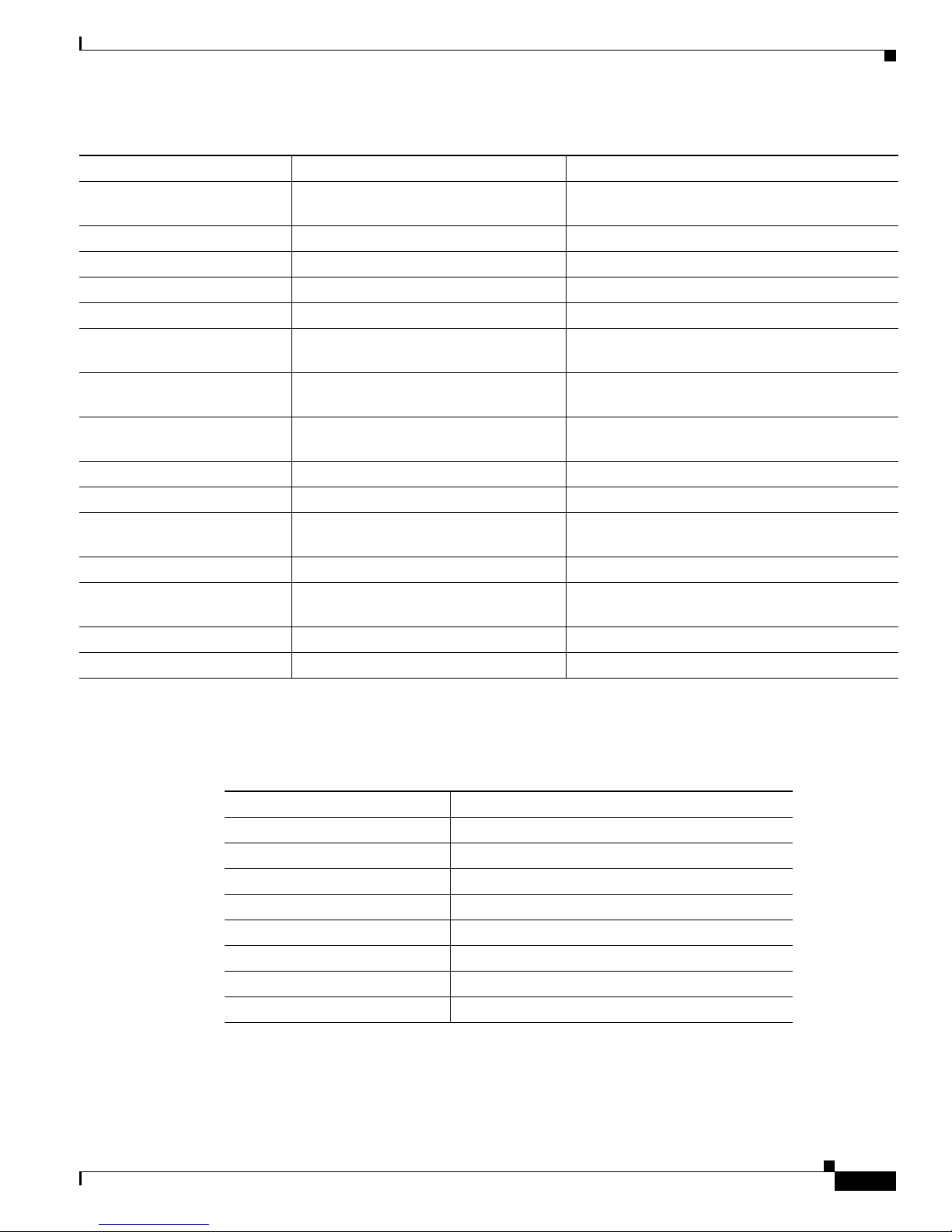
• FACILITY is a code consisting of two or more uppercase letters that show the facility to which the
message refers. A facility can be a hardware device, a protocol, or a module of the system software.
Table 1-1 lists the switch facility codes. These messages are described in Chapter 2, “Messages and
Recovery Procedures,” in alphabetical order by facility code with the most severe (lowest number)
errors described first.
Page 16

1-2
Cisco ME 3400 and 2400 Ethernet Access Switch System Message Guide
OL-9641-01
Chapter 1 System Message Overview
How to Read System Messages
Table 1-1 Facility Codes
Facility Code Description Location
ACLMGR ACL manager “ACLMGR Messages” section on page 2-3
BSPATCH Boot loader patch “BSPATCH Messages” section on page 2-7
DOT1X IEEE 802.1x “DHCP_SNOOPING Messages” section on
page 2-8
DTP Dynamic Trunking Protocol “EC Messages” section on page 2-16
EC EtherChannel “EC Messages” section on page 2-16
ETHCNTR Ethernet Controller “ETHCNTR Messages” section on page 2-21
FRNTEND_CTRLR Front-end controller “FRNTEND_CTRLR Messages” section on
page 2-21
GBIC_SECURITY Gigabit Interface Converter (GBIC)
module and small form-factor pluggable
(SFP) module security
“GBIC_SECURITY Messages” section on
page 2-22
GBIC_SECURITY_CRYPT GBIC and SFP module security “GBIC_SECURITY_CRYPT Messages” section
on page 2-23
GBIC_SECURITY_UNIQUE GBIC and SFP module security “GBIC_SECURITY_UNIQUE Messages”
section on page 2-24
HARDWARE Hardware “HARDWARE Messages” section on page 2-24
HLFM Local forwarding manager “HLFM Messages” section on page 2-26
HCPU_PROT_MGR CPU Protection Manager “HCPU_PROT_MGR Messages” section on
page 2-26
IGMP_QUERIER Internet Group Management Protocol
(IGMP) querier
“IGMP_QUERIER Messages” section on
page 2-30
MAC_LIMIT MAC address table entries “MAC_LIMIT Messages” section on page 2-31
MAC_MOVE Host activity “MAC_MOVE Messages” section on page 2-32
PHY PHY “PHY Messages” section on page 2-32
PIMSN Protocol Independent Multicast (PIM)
snooping
“PIMSN Messages” section on page 2-34
PLATFORM Low-level platform-specific “PLATFORM Messages” section on page 2-34
PLATFORM_PBR Platform policy-based routing (Cisco
ME 3400 switches only)
“PLATFORM_PBR Messages” section on
page 2-35
PLATFORM_PM Platform port manager “PLATFORM_PM Messages” section on
page 2-37
PLATFORM_SPAN Platform Switched Port Analyzer “PLATFORM_SPAN Messages” section on
page 2-38
PLATFORM_UCAST Platform unicast routing (Cisco ME
3400 switches only)
“PLATFORM_UCAST Messages” section on
page 2-38
PLATFORM_VLAN Platform VLAN “PLATFORM_VLAN Messages” section on
page 2-40
PM Port manager “PM Messages” section on page 2-41
Page 17
1-3
Cisco ME 3400 and 2400 Ethernet Access Switch System Message Guide
OL-9641-01
Chapter 1 System Message Overview
How to Read System Messages
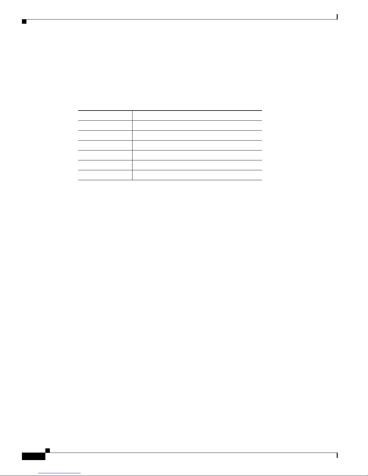
• SEVERITY is a single-digit code from 0 to 7 that reflects the severity of the condition. The lower
the number, the more serious the situation. Table 1-2 lists the message severity levels.
• MNEMONIC is a code that uniquely identifies the message.
PORT_SECURITY Port security “PORT_SECURITY Messages” section on
page 2-48
QOSMGR QoS manager “QOSMGR Messages” section on page 2-49
RMON Remote Network Monitoring (RMON) “RMON Messages” section on page 2-58
SPAN Switched Port Analyzer “SPAN Messages” section on page 2-58
SPANTREE Spanning Tree “SPANTREE Messages” section on page 2-59
SPANTREE_FAST Spanning-tree fast convergence “SPANTREE_FAST Messages” section on
page 2-66
SPANTREE_VLAN_SW Spanning-tree VLAN switch “SPANTREE_VLAN_SW Messages” section on
page 2-66
STORM_CONTROL Storm control “STORM_CONTROL Messages” section on
page 2-66
SUPERVISOR Supervisor ASIC “SUPERVISOR Messages” section on page 2-67
SUPQ Supervisor queue “SUPQ Messages” section on page 2-67
SW_DAI Dynamic ARP inspection (Cisco ME
3400 switches only)
“SW_DAI Messages” section on page 2-69
SW_VLAN VLAN manager “SW_VLAN Messages” section on page 2-71
TCAMMGR Ternary content addressable memory
manager
“TCAMMGR Messages” section on page 2-75
UDLD UniDirectional Link Detection “UDLD Messages” section on page 2-77
VQPCLIENT VLAN Query Protocol client “VQPCLIENT Messages” section on page 2-79
Table 1-1 Facility Codes (continued)
Facility Code Description Location
Table 1-2 Message Severity Levels
Severity Level Description
0 – emergency System is unusable.
1 – alert Immediate action required.
2 – critical Critical condition.
3 – error Error condition.
4 – warning Warning condition.
5 – notification Normal but significant condition.
6 – informational Informational message only.
7 – debugging Message that appears during debugging only.
Page 18
1-4
Cisco ME 3400 and 2400 Ethernet Access Switch System Message Guide
OL-9641-01
Chapter 1 System Message Overview
Error Message Traceback Reports
• Message-text is a text string describing the condition. This portion of the message sometimes
contains detailed information about the event, including terminal port numbers, network addresses,
or addresses that correspond to locations in the system memory address space. Because the
information in these variable fields changes from message to message, it is represented here by short
strings enclosed in square brackets ([ ]). A decimal number, for example, is represented as [dec].
Table 1-3 lists the variable fields in messages.
This example shows a partial switch system message:
00:00:46: %LINK-3-UPDOWN: Interface Port-channel1, changed state to up
00:00:47: %LINK-3-UPDOWN: Interface GigabitEthernet0/1, changed state to up
00:00:47: %LINK-3-UPDOWN: Interface GigabitEthernet0/2, changed state to up
00:00:48: %LINEPROTO-5-UPDOWN: Line protocol on Interface Vlan1, changed state to down
00:00:48: %LINEPROTO-5-UPDOWN: Line protocol on Interface GigabitEthernet0/1, changed
state to down 2
*Mar 1 18:46:11: %SYS-5-CONFIG_I: Configured from console by vty2 (10.34.195.36)
18:47:02: %SYS-5-CONFIG_I: Configured from console by vty2 (10.34.195.36)
*Mar 1 18:48:50.483 UTC: %SYS-5-CONFIG_I: Configured from console by vty2 (10.34.195.36)
Error Message Traceback Reports
Some messages describe internal errors and contain traceback information. This information is very
important and should be included when you report a problem to your technical support representative.
This message example includes traceback information:
-Process= "Exec", level= 0, pid= 17
-Traceback= 1A82 1AB4 6378 A072 1054 1860
Some system messages ask you to copy the error messages and take further action. These online tools
also provide more information about system error messages.
Output Interpreter
The Output Interpreter provides additional information and suggested fixes based on the output of many
CLI commands, such as the the show tech-support privileged EXEC command. You can access the
Output Interpreter at this URL:
https://www.cisco.com/cgi-bin/Support/OutputInterpreter/home.pl
Table 1-3 Representation of Variable Fields in Messages
Representation Type of Information
[dec] Decimal integer
[char] Single character
[chars] Character string
[enet] Ethernet address (for example, 0000.FEED.00C0)
[hex] Hexadecimal integer
[inet] Internet address
Page 19

1-5
Cisco ME 3400 and 2400 Ethernet Access Switch System Message Guide
OL-9641-01
Chapter 1 System Message Overview
Error Message Traceback Reports
Bug Toolkit
The Bug Toolkit provides information on open and closed caveats, and allows you to search for all
known bugs in a specific Cisco IOS Release. You can access the Bug Toolkit at this URL:
http://www.cisco.com/cgi-bin/Support/Bugtool/home.pl
Contacting TAC
If you cannot determine the nature of the error, see the “Obtaining Technical Assistance” section on
page xi for further information.
Page 20

1-6
Cisco ME 3400 and 2400 Ethernet Access Switch System Message Guide
OL-9641-01
Chapter 1 System Message Overview
Error Message Traceback Reports
Page 21

CHA P TER
2-1
Cisco ME 3400 and 2400 Ethernet Access Switch System Message Guide
OL-9641-01
2
Messages and Recovery Procedures
This chapter describes the Cisco ME 3400 and 2400 switches system messages in alphabetical order by
facility. Note that some messages apply only to the Cisco ME 3400 switch and are never seen on a Cisco
ME 2400 switch.
Within each facility, the messages are listed by severity levels 0 to 7: 0 is the highest severity level, and
7 is the lowest severity level. Each message is followed by an explanation and a recommended action.
Note The messages listed in this chapter do not include the hostname or the date/time stamp designation that
displays only if the software is configured for system log messaging.
The chapter includes these message facilities:
• ACLMGR Messages, page 2-3
• BADTRANSCEIVER Messages, page 2-7
• BSPATCH Messages, page 2-7
• DHCP_SNOOPING Messages, page 2-8
• EC Messages, page 2-16
• EC Messages, page 2-16
• ETHCNTR Messages, page 2-21
• FRNTEND_CTRLR Messages, page 2-21
• GBIC_SECURITY Messages, page 2-22
• GBIC_SECURITY_CRYPT Messages, page 2-23
• GBIC_SECURITY_UNIQUE Messages, page 2-24
• HARDWARE Messages, page 2-24
• HCPU_PROT_MGR Messages, page 2-26
• HLFM Messages, page 2-26
• IDBMAN Messages, page 2-27 (Cisco ME 3400 switch only)
• IGMP_QUERIER Messages, page 2-30
• MAC_LIMIT Messages, page 2-31
• MAC_MOVE Messages, page 2-32
• PHY Messages, page 2-32
Page 22

2-2
Cisco ME 3400 and 2400 Ethernet Access Switch System Message Guide
OL-9641-01
Chapter 2 Messages and Recovery Procedures
• PIMSN Messages, page 2-34
• PLATFORM Messages, page 2-34
• PLATFORM_PBR Messages, page 2-35 (Cisco ME 3400 switch only)
• PLATFORM_PM Messages, page 2-37
• PLATFORM_SPAN Messages, page 2-38
• PLATFORM_UCAST Messages, page 2-38 (Cisco ME 3400 switch only)
• PLATFORM_VLAN Messages, page 2-40
• PM Messages, page 2-41
• PORT_SECURITY Messages, page 2-48
• QOSMGR Messages, page 2-49
• RMON Messages, page 2-58
• SPAN Messages, page 2-58
• SPANTREE Messages, page 2-59
• SPANTREE_FAST Messages, page 2-66
• SPANTREE_VLAN_SW Messages, page 2-66
• STORM_CONTROL Messages, page 2-66
• SUPERVISOR Messages, page 2-67
• SUPQ Messages, page 2-67
• SW_DAI Messages, page 2-69 (Cisco ME 3400 switch only)
• SW_VLAN Messages, page 2-71
• TCAMMGR Messages, page 2-75
• UDLD Messages, page 2-77
• VQPCLIENT Messages, page 2-79
Page 23

2-3
Cisco ME 3400 and 2400 Ethernet Access Switch System Message Guide
OL-9641-01
Chapter 2 Messages and Recovery Procedures
ACLMGR Messages
ACLMGR Messages
This section contains the access control list (ACL) manager messages. Most messages in this section are
the result of a switch memory shortage, which includes hardware memory and label space but not CPU
memory. Both kinds of memory shortages are described.
Error Message ACLMGR-2-NOMAP: Cannot create ACL Manager data structures for VLAN Map
[chars].
Explanation
This message means that the ACL manager was unable to allocate the data structures
needed to describe a VLAN map in a form that can be loaded into hardware. This error is most likely
caused by lack of free memory. [chars] is the VLAN map name.
Recommended Action Reduce other system activity to ease memory demands.
Error Message ACLMGR-2-NOVLB: Cannot create memory block for VLAN [dec].
Explanation
This message means that the ACL manager was unable to save per-VLAN information
needed for its correct operation. Some per-interface features, such as access groups or VLAN maps,
will not be configured correctly. [dec] is the VLAN number.
Recommended Action Use a less complicated configuration that requires less memory.
Error Message ACLMGR-2-NOVMR: Cannot create VMR data structures for access list
[chars].
Explanation
This message means that the ACL manager was unable to allocate the value-mask result
(VMR) data structures needed to describe an ACL in a form that can be loaded into hardware. This
error is most likely caused by lack of available memory. [chars] is the access-list name.
Recommended Action Use a less complicated configuration that requires less memory.
Error Message ACLMGR-3-ACLTCAMFULL: Acl Tcam Full. Drop packets on Output Acl label
[dec] on [chars] [chars].
Explanation
This message means that there are too many ACLs configured for the platform-specific
ACL TCAM table to support. [dec] is the label number, and [chars] represents the layer. The first
[chars] is for Layer 3; the second is for Layer 2. If only one layer of TCAM is full, only one string
is displayed, and the other string is NULL.
Recommended Action Reduce the number of IP or MAC access lists to be applied to interfaces.
Page 24

2-4
Cisco ME 3400 and 2400 Ethernet Access Switch System Message Guide
OL-9641-01
Chapter 2 Messages and Recovery Procedures
ACLMGR Messages
Error Message ACLMGR-3-AUGMENTFAIL: Augmenting of access-map [chars] on [chars]
label [dec] failed.
Explanation
This message means that the system ran out of CPU DRAM when attempting to merge
internally required elements with the configured access maps. The first [chars] is the access-map
name, the second [chars] is the direction in which the map was applied (input or output), and [dec]
is the label number.
Recommended Action Reduce other system activity to ease memory demands.
Error Message ACLMGR-3-IECPORTLABELERROR: ACL labels are out-of-sync on interface
[chars], label [dec] is not available on asic [dec].
Explanation
This message means that an internal software error has occurred. [chars] is the interface
name. The first [dec] is the label associated with the ACL, and the second [dec] is the ASIC number.
Recommended Action Copy the message exactly as it appears on the console or in the system log.
Research and attempt to resolve the error by using the Output Interpreter. Use the Bug Toolkit to
look for similar reported problems. If you still require assistance, open a case with the TAC, or
contact your Cisco technical support representative, and provide the representative with the gathered
information. For more information about these online tools and about contacting Cisco, see the “Error
Message Traceback Reports” section on page 1-4.
Error Message ACLMGR-3-INSERTFAIL: Insert of access-map [chars] #[dec] into [chars]
label [dec] failed.
Explanation
This message means that the system ran out of CPU memory when trying to merge
sections of an access map. The first [chars] is the map name, and the second [chars] is the direction
in which the map was applied. The first [dec] is the entry number, and the second [dec] is the label
number.
Recommended Action Reduce other system activity to ease memory demands. For example, remove
any ACLs that have been defined but are not now used. Use simpler ACLs with fewer access control
entries (ACEs). Use fewer VLANs, and remove any unneeded VLANs from the VLAN database.
Error Message ACLMGR-3-INTTABLE: Not in truth table: VLMAP [dec] RACL [dec] Mcb [dec]
Feat [dec].
Explanation
This message means that an unrecoverable software error occurred while trying to
merge the configured input features. [dec] are internal action codes.
Recommended Action Copy the message exactly as it appears on the console or in the system log.
Research and attempt to resolve the error by using the Output Interpreter. Enter the show
running-config user EXEC command to gather data that might help identify the nature of the error.
Use the Bug Toolkit to look for similar reported problems. If you still require assistance, open a case
with the TAC, or contact your Cisco technical support representative, and provide the representative
with the gathered information. For more information about these online tools and about contacting
Cisco, see the “Error Message Traceback Reports” section on page 1-4.
Page 25

2-5
Cisco ME 3400 and 2400 Ethernet Access Switch System Message Guide
OL-9641-01
Chapter 2 Messages and Recovery Procedures
ACLMGR Messages
Error Message ACLMGR-3-MAXRECURSION: Too many ([dec]) levels of recursion while
merging ACLs (code [dec]).
Explanation
This message means that the configuration is too complicated for the platform-specific
ACL merge code to support. The most likely cause is too many separate access lists in a single
VLAN map or policy map. The first [dec] is the number of levels of recursion. The second [dec] is
an internal code number of the merge stage that encountered the problem.
Recommended Action Reduce the number of IP or MAC access lists (considered separately) in any
one VLAN or policy map to fewer than the number of levels reported by this log message.
Error Message ACLMGR-3-MERGEFAIL: [chars] ACL merge error [dec] ([chars]) on [chars]
label [dec].
Explanation
This message means that the ACL manager was unable to complete the merge of the
configured features into a form suitable for loading into the hardware. Packets potentially affected
by this feature will be sent to the CPU for processing instead. The most likely cause is specifying
an ACL that is too large or too complex for the system. The first [chars] is the ACL-type error (ip
or mac), the first [dec] is the error code, the second [chars] is the message string for the preceding
error code, the second [dec] is the label number, and the third [chars] is either input or output.
Recommended Action Specify a smaller and less complicated configuration.
Error Message ACLMGR-3-NOLABEL: Cannot allocate [chars] label for interface [chars].
Explanation
This message means that the ACL manager was unable to allocate a label for the
features on this interface. This means that the hardware cannot be programmed to implement the
features, and packets for this interface will be filtered in software. There is a limit of 256 labels per
direction. The first [chars] is the direction (input or output); the second [chars] is the interface name.
Recommended Action Use a simpler configuration. Use the same ACLs on multiple interfaces, if
possible.
Error Message ACLMGR-3-OUTTTABLE: Not in truth table: RACL [dec] VLMAP [dec].
Explanation
This message means that an unrecoverable software error occurred while trying to
merge the configured output features. [dec] are internal action codes.
Recommended Action Copy the message exactly as it appears on the console or in the system log.
Research and attempt to resolve the error by using the Output Interpreter. Enter the show
running-config user EXEC command to gather data that might help identify the nature of the error.
Use the Bug Toolkit to look for similar reported problems. If you still require assistance, open a case
with the TAC, or contact your Cisco technical support representative, and provide the representative
with the gathered information. For more information about these online tools and about contacting
Cisco, see the “Error Message Traceback Reports” section on page 1-4.
Page 26

2-6
Cisco ME 3400 and 2400 Ethernet Access Switch System Message Guide
OL-9641-01
Chapter 2 Messages and Recovery Procedures
ACLMGR Messages
Error Message ACLMGR-3-PACLTTABLE: Not in truth table: IPSrcGrd [dec] PACL [dec].
Explanation
This message means that an unrecoverable software error occurred while trying to
merge the configured port ACL features. The first [dec] is the action specified by IP source guard,
and the second [dec] is the action specified by the port ACL.
Recommended Action Copy the message exactly as it appears on the console or in the system log.
Research and attempt to resolve the error by using the Output Interpreter. Enter the show
running-config user EXEC command to gather data that might help identify the nature of the error.
Use the Bug Toolkit to look for similar reported problems. If you still require assistance, open a case
with the TAC, or contact your Cisco technical support representative, and provide the representative
with the gathered information. For more information about these online tools and about contacting
Cisco, see the “Error Message Traceback Reports” section on page 1-4.
Error Message ACLMGR-3-QOSTTABLE: Not in truth table: ACL [dec] in map, action [dec].
Explanation
This message means that a software error occurred while trying to merge a QoS policy
map. The first [dec] is the ACL number, and the second [dec] is the action corresponding to the
specified ACL number.
Recommended Action Copy the message exactly as it appears on the console or in the system log.
Research and attempt to resolve the error by using the Output Interpreter. Use the Bug Toolkit to
look for similar reported problems. If you still require assistance, open a case with the TAC, or
contact your Cisco technical support representative, and provide the representative with the gathered
information. For more information about these online tools and about contacting Cisco, see the “Error
Message Traceback Reports” section on page 1-4.
Error Message ACLMGR-3-RELOADED: Reloading [chars] label [dec] feature.
Explanation
This message means that the ACL manager is now able to load more of the configured
features on this label into the hardware. One or more features had previously been unloaded because
of lack of space. [chars] is the direction (input or output), and [dec] is the label number.
Recommended Action No action is required.
Error Message ACLMGR-3-UNKNOWNACTION: Unknown VMR access group action [hex].
Explanation
This message means that an internal software error has occurred. [hex] is an internal
action code.
Recommended Action Copy the message exactly as it appears on the console or in the system log.
Research and attempt to resolve the error by using the Output Interpreter. Use the Bug Toolkit to
look for similar reported problems. If you still require assistance, open a case with the TAC, or
contact your Cisco technical support representative, and provide the representative with the gathered
information. For more information about these online tools and about contacting Cisco, see the “Error
Message Traceback Reports” section on page 1-4.
Page 27

2-7
Cisco ME 3400 and 2400 Ethernet Access Switch System Message Guide
OL-9641-01
Chapter 2 Messages and Recovery Procedures
BADTRANSCEIVER Messages
Error Message ACLMGR-3-UNLOADING: Unloading [chars] label [dec] feature.
Explanation
This message means that the ACL manager was unable to fit the complete configuration
into the hardware, so some features will be applied in software. This prevents some or all of the
packets in a VLAN from being forwarded in hardware and requires them to be forwarded by the
CPU. Multicast packets might be dropped entirely instead of being forwarded. [chars] is the
direction (input or output), and [dec] is the label number.
Recommended Action Use a simpler configuration. Use the same ACLs on multiple interfaces, if
possible.
BADTRANSCEIVER Messages
This section contains the BADTRANSCEIVER message.
Error Message BADTRANSCEIVER, PHY, LOG_WARNING: An innapropriate transceiver has
been inserted in interface [chars].
Explanation
This message means that a defective module is installed in the specified interface.
[chars] is the interface.
Recommended Action Remove the transceiver. If it was purchased from Cisco, contact your Cisco
representative to have the transceiver replaced.
BSPATCH Messages
This section contains boot loader patch messages.
Error Message BSPATCH-1-RELOAD: System will reboot to activate newly patched Boot
Loader.
Explanation
This message means that the switch will automatically reboot after the boot loader is
patched.
Recommended Action If this message recurs, copy it exactly as it appears on the console or in the
system log. Research and attempt to resolve the error by using the Output Interpreter. Use the Bug
Toolkit to look for similar reported problems. If you still require assistance, open a case with the
TAC, or contact your Cisco technical support representative, and provide the representative with the
gathered information. For more information about these online tools and about contacting Cisco, see the
“Error Message Traceback Reports” section on page 1-4.
Page 28

2-8
Cisco ME 3400 and 2400 Ethernet Access Switch System Message Guide
OL-9641-01
Chapter 2 Messages and Recovery Procedures
DHCP_SNOOPING Messages
Error Message BSPATCH-1-PATCHED: Boot Loader patch ([chars]) installed.
Explanation
This message means that a boot loader patch is installed successfully. [chars] is the
SDRAM refresh timer register setting.
Recommended Action If this message recurs, copy it exactly as it appears on the console or in the
system log. Research and attempt to resolve the error by using the Output Interpreter. Use the Bug
Toolkit to look for similar reported problems. If you still require assistance, open a case with the
TAC, or contact your Cisco technical support representative, and provide the representative with the
gathered information. For more information about these online tools and about contacting Cisco, see the
“Error Message Traceback Reports” section on page 1-4.
Error Message BSPATCH-3-FAILED: Failed to install Boot Loader patch ([chars]).
Explanation
This message means that the switch failed to apply a boot loader patch. [chars] is the
SDRAM refresh timer register setting.
Recommended Action Copy the message exactly as it appears on the console or in the system log.
Research and attempt to resolve the error by using the Output Interpreter. Use the Bug Toolkit to
look for similar reported problems. If you still require assistance, open a case with the TAC, or
contact your Cisco technical support representative, and provide the representative with the gathered
information. For more information about these online tools and about contacting Cisco, see the “Error
Message Traceback Reports” section on page 1-4.
DHCP_SNOOPING Messages
This section contains the DHCP snooping messages.
Error Message DHCP_SNOOPING-3-DHCP_SNOOPING_INTERNAL_ERROR: DHCP Snooping internal
error, [chars].
Explanation
This message means that a software sanity check failed in the DHCP snooping process.
[chars] is the error.
Recommended Action Copy the message exactly as it appears on the console or in the system log.
Research and attempt to resolve the error by using the Output Interpreter. Use the Bug Toolkit to
look for similar reported problems. If you still require assistance, open a case with the TAC, or
contact your Cisco technical support representative, and provide the representative with the gathered
information. For more information about these online tools and about contacting Cisco, see the
“Error Message Traceback Reports” section on page 1-4.
Error Message DHCP_SNOOPING-4-AGENT_OPERATION_FAILED: DHCP snooping binding
transfer failed. [chars].
Explanation
This message means that the DHCP snooping binding transfer process failed because of
the specified reason for failure. [chars] is the reason for failure.
Recommended Action No action is required.
Page 29

2-9
Cisco ME 3400 and 2400 Ethernet Access Switch System Message Guide
OL-9641-01
Chapter 2 Messages and Recovery Procedures
DHCP_SNOOPING Messages
Error Message DHCP_SNOOPING-4-AGENT_OPERATION_FAILED_N: DHCP snooping binding
transfer failed ([dec]). [chars].
Explanation
This message means that the DHCP snooping binding transfer process failed because of
the specified reason for failure [dec] is the number of failures, and [chars] is the reason for the
failure. This message is rate-limited.
Recommended Action No action is required.
Error Message DHCP_SNOOPING-4-DHCP_SNOOPING_ERRDISABLE_WARNING: DHCP Snooping
received [dec] DHCP packets on interface [chars].
Explanation
This message means that the switch detected a DHCP packet rate-limit violation on the
specified interface and put the interface in the error-disabled state. [dec] is the number of DCHP
packets, and [chars] is the interface.
Recommended Action No action is required.
Error Message DHCP_SNOOPING-4-DHCP_SNOOPING_PVLAN_WARNING: DHCP Snooping
configuration may not take effect on secondary vlan [dec]. [chars]
Explanation
This message means that if private VLANs are configured, the DHCP Snooping
configuration on the primary VLAN automatically propagates to all the secondary VLANs. [dec] is
the VLAN IDs of the secondary VLANs, and [chars] is the warning.
Recommended Action No action is required.
Error Message DHCP_SNOOPING-4-IP_SOURCE_BINDING_PVLAN_WARNING: IP source filter may
not take effect on secondary vlan [dec] where IP source binding is configured.
[chars].
Note This message applies only to the Cisco ME 3400 switch.
Explanation This message means that if private VLANs are configured, the IP-source-guard filter on the
primary VLAN automatically propagates to all secondary VLANs. [dec] is the secondary VLAN, and
[chars] is the warning.
Recommended Action No action is required.
Error Message DHCP_SNOOPING-4-IP_SOURCE_BINDING_NON_EXISTING_VLAN_WARNING: IP
source binding is configured on non existing vlan [dec].
Note This message applies only to the Cisco ME 3400 switch.
Explanation The message means that an IP source binding was configured on a VLAN that has not
been configured yet. [dec] is the VLAN.
Recommended Action No action is required.
Page 30

2-10
Cisco ME 3400 and 2400 Ethernet Access Switch System Message Guide
OL-9641-01
Chapter 2 Messages and Recovery Procedures
DHCP_SNOOPING Messages
Error Message DHCP_SNOOPING-4-NTP_NOT_RUNNING: NTP is not running; reloaded binding
lease expiration times are incorrect.
Explanation
This message means that if the DHCP snooping database agent loads the DHCP
snooping bindings and NTP is not running, the calculated lease duration for the bindings is
incorrect.
Recommended Action Configure NTP on the switch to provide an accurate time and date for the
system clock. Then disable and re-enable DHCP snooping to clear the DHCP snooping binding
database.
Error Message DHCP_SNOOPING-4-QUEUE_FULL: Fail to enqueue DHCP packet into
processing queue: [chars], the queue is most likely full and the packet will be
dropped.
Explanation
This message means that the CPU is receiving DHCP packets a higher rate than the
DHCP snooping process can handle. These DHCP packets are dropped to prevent a denial of service
attack. [chars] is the warning.
Recommended Action No action is required.
Error Message DHCP_SNOOPING-4-STANDBY_AGENT_OPERATION_FAILED: DHCP snooping binding
transfer failed on the Standby Supervisor. [chars].
Explanation
This message means that the DHCP snooping binding transfer process failed on a
standby supervisor engine. [chars] is the standby supervisor engine.
Recommended Action No action is required.
Error Message DHCP_SNOOPING-6-AGENT_OPERATION_SUCCEEDED: DHCP snooping database
[chars] succeeded.
Explanation
This message means that the DHCP binding transfer process succeeded. [chars] is the
DCHP snooping database.
Recommended Action No action is required.
Error Message DHCP_SNOOPING-6-BINDING_COLLISION: Binding collision. [dec] bindings
ignored.
Explanation
This message means that the specified number of bindings were ignored when the
switch read the database file. The bindings from the database file have MAC address and VLAN
information that a configured DHCP snooping binding already uses.
Recommended Action No action is required.
Page 31

2-11
Cisco ME 3400 and 2400 Ethernet Access Switch System Message Guide
OL-9641-01
Chapter 2 Messages and Recovery Procedures
DOT1X Messages
Error Message DHCP_SNOOPING-6-INTERFACE_NOT_VALID: Interface not valid. [dec]
bindings ignored.
Explanation
This message means that the specified number of bindings were ignored when the
switch read the database file because the interface in binding database is not available, the interface
is a routed port, or the interface is a DHCP snooping-trusted Layer 2 interface. [dec] is the number
of bindings that the switch ignores.
Recommended Action No action is required.
Error Message DHCP_SNOOPING-6-LEASE_EXPIRED: Lease Expired. [dec] bindings ignored.
Explanation
This message means that the specified number of bindings were ignored when the
switch read the database file because the DHCP lease expired. [dec] is the number of bindings.
Recommended Action No action is required.
Error Message DHCP_SNOOPING-6-PARSE_FAILURE: Parsing failed for [dec] bindings.
Explanation
This message means that the specified number of bindings were ignored when the
switch read the database file because the database read operation failed. [dec] is the number of
bindings.
Recommended Action No action is required.
Error Message DHCP_SNOOPING-6-VLAN_NOT_SUPPORTED: Vlan not supported. [dec] bindings
ignored.
Explanation
This message means that the specified number of bindings were ignored when the
switch read the database file because VLAN is no longer configured on the switch. [dec] is the
number of bindings that the switch ignores.
Recommended Action No action required.
DOT1X Messages
This section contains the 802.1x messages.
Error Message DOT1X-4-MEM_UNAVAIL: Memory was not available to perform the
802.1X action.
Explanation
This message means that the system memory is not sufficient to perform the 802.1x
authentication.
Recommended Action Reduce other system activity to reduce memory demands.
Page 32

2-12
Cisco ME 3400 and 2400 Ethernet Access Switch System Message Guide
OL-9641-01
Chapter 2 Messages and Recovery Procedures
DOT1X Messages
Error Message DOT1X-4-MSG_ERR: Unknown message event received.
Explanation
This message means that the 802.1x process received an unknown message event.
Recommended Action Restart the 802.1x process by entering the dot1x system-auth-control global
configuration command. If this message recurs, reload the device.
Error Message DOT1X-4-PROC_START_ERR: Dot1x unable to start.
Explanation
This message means that the system failed to create the 802.1x process.
Recommended Action Restart the 802.1x process by entering the dot1x system-auth-control global
configuration command. If this message recurs, reload the device.
Error Message DOT1X-4-UNKN_ERR: An unknown operational error occurred.
Explanation
This message means that the 802.1x process cannot operate because of an internal
system error.
Recommended Action No action is required.
Error Message DOT1X-5-ERR_CHANNELLING: Dot1x can not be enabled on Channelling
ports.
Explanation
This message means that 802.1x could not be enabled on the channeling port. Trying to
set 802.1x port-control to auto or force-unauthorized (force_unauth) mode on a channeling port,
which is not allowed, caused this condition.
Recommended Action Disable channeling on the interface, and then enable 802.1x.
Error Message DOT1X-5-ERR_DYNAMIC: Dot1x can not be enabled on Dynamic ports.
Explanation
This message means that 802.1x could not be enabled on the dynamic mode port. Trying
to set 802.1x port-control to auto or force-unauthorized (force_unauth) mode on a dynamic mode
port, which is not allowed, caused this condition.
Recommended Action Disable dynamic mode on the interface, and then enable 802.1x.
Error Message DOT1X-5-ERR_DYNAMIC_VLAN: Dot1x can not be enabled on dynamic VLAN
ports.
Explanation
This message means that 802.1x could not be enabled on the dynamic VLAN port.
Trying to set 802.1x port-control to auto or force-unauthorized (force_unauth) mode on a dynamic
VLAN port, which is not allowed, caused this condition.
Recommended Action Disable dynamic VLAN configuration on the interface, and then enable
802.1x.
Page 33

2-13
Cisco ME 3400 and 2400 Ethernet Access Switch System Message Guide
OL-9641-01
Chapter 2 Messages and Recovery Procedures
DOT1X Messages
Error Message DOT1X-5-ERR_INVALID_AAA_ATTR: Got invalid AAA attribute settings
[chars].
Explanation
This message means that the authorization settings obtained are either unsupported or
invalid. [chars] is the text received from the RADIUS server.
Recommended Action Change the settings to valid values.
Error Message DOT1X-5-ERR_INVALID_TUNNEL_MEDIUM_TYPE: Got an invalid value [chars]
for TUNNEL_MEDIUM_TYPE [chars].
Explanation
This message means that the provided tunnel medium is either unsupported or invalid.
[chars] is the text received from the RADIUS server.
Recommended Action Change the value to a valid tunnel medium.
Error Message DOT1X-5-ERR_INVALID_TUNNEL_TYPE: Got an invalid value of [chars] for
TUNNEL_TYPE [chars].
Explanation
This message means that the provided tunnel type is either unsupported or invalid.
[chars] is the text received from the RADIUS server.
Recommended Action Change the value to a valid tunnel type.
Error Message DOT1X-5-ERR_PER_USR_IP_ACL: Applied per-user IP ACL was unsuccessful
on interface [chars].
Explanation
This message means that 802.1x could not apply a per-user IP ACL, possibly because
of an invalid per-user base (or pub) ACL from the RADIUS server. [chars] is the interface.
Recommended Action Examine the RADIUS pub ACL, and configure a valid one.
Error Message DOT1X-5-ERR_PER_USR_MAC_ACL: Applied per-user MAC ACL was unsuccessful
on interface [chars].
Explanation
This message means that 802.1x could not apply a per-user MAC ACL, possibly
because of an invalid per-user base (or pub) ACL from the RADIUS server. [chars] is the interface.
Recommended Action Examine the RADIUS pub ACL, and configure a valid one.
Error Message DOT1X-5-ERR_PROTO_TUNNELLING: Dot1x can not be enabled on protocol
tunnelling enabled ports.
Explanation
This message means that 802.1x could not be enabled on the protocol-tunneling-enabled
port. Trying to set 802.1x port-control to auto or force-unauthorized (force_unauth) mode on a
protocol-tunneling-enabled port, which is not allowed, caused this condition.
Recommended Action Change the access VLAN on the interface, and then enable 802.1x.
Page 34

2-14
Cisco ME 3400 and 2400 Ethernet Access Switch System Message Guide
OL-9641-01
Chapter 2 Messages and Recovery Procedures
DOT1X Messages
Error Message DOT1X-5-ERR_PVLAN_TRUNK:Dot1x can not be enabled on private VLAN trunk
ports
Explanation
This message means that 802.1x could not be enabled on private VLAN ports on which
trunking is enabled.
Recommended Action No action is required.
Error Message DOT1X-5-ERR_RSPAN_VLAN: Dot1x can not be enabled on ports configured
in Remote SPAN vlan.
Explanation
This message means that 802.1x could not be enabled on the remote SPAN VLAN port.
Trying to set 802.1x port-control to auto or force-unauthorized (force_unauth) mode on a port that
is in a remote SPAN VLAN, which is not allowed, caused this condition.
Recommended Action Disable remote SPAN on the VLAN, and then enable 802.1x.
Error Message DOT1X-5-ERR_SPANDST: Dot1x can not be enabled on [chars]. It is
configured as a SPAN Dest port.
Explanation
This message means that 802.1x cannot be enabled on a port that is a SPAN destination
port because these features are mutually exclusive. [chars] is the port.
Recommended Action Remove the SPAN destination port from the SPAN session before
reconfiguring 802.1x on the port.
Error Message DOT1X-5-ERR_TRUNK: Dot1x can not be enabled on Trunk port.
Explanation
This message means that 802.1x could not be enabled on the trunk port. Trying to set
802.1x port control to auto or force-unauthorized (force_unauth) mode on a trunk port, which is not
allowed, caused this condition.
Recommended Action Disable trunking on the interface, and then enable 802.1x.
Error Message DOT1X-5-ERR_TUNNEL: Dot1x can not be enabled on 802.1q tunnelling
enabled ports.
Explanation
This message means that 802.1x could not be enabled on the 802.1Q
tunneling-enabled-port. Trying to set 802.1x port-control to auto or force-unauthorized
(force_unauth) mode on a 802.1Q-tunnel-enabled port, which is not allowed, caused this condition.
Recommended Action Disable 802.1Q tunneling on the interface, and then enable 802.1x.
Error Message DOT1X-5-ERR_VLAN_INTERNAL: The VLAN [dec] is being used internally and
cannot be assigned for use on the Dot1x port [chars] Vlan.
Explanation
This message means that the VLAN is used internally and cannot be assigned again for
use on this port. [dec] is the VLAN ID. [chars] is the port number.
Recommended Action Update the configuration to not use this VLAN.
Page 35

2-15
Cisco ME 3400 and 2400 Ethernet Access Switch System Message Guide
OL-9641-01
Chapter 2 Messages and Recovery Procedures
DOT1X Messages
Error Message DOT1X-5-ERR_VLAN_INVALID: The VLAN [dec] is invalid and cannot be
assigned for use on the 802.1X port [chars] Vlan.
Explanation
This message means that the specified VLAN is out of range and cannot be assigned for
use on this port. [dec] is the VLAN ID. [chars] is the port number.
Recommended Action Update the configuration to use a valid VLAN.
Error Message DOT1X-5-ERR_VLAN_NOT_ASSIGNABLE: RADIUS tried to assign a VLAN to
dot1x port [chars] whose VLAN cannot be assigned.
Explanation
This message means that the RADIUS server tried to assign a VLAN to a supplicant on
a port whose VLAN cannot be changed, such as a routed port. [chars] is the port number.
Recommended Action Change the specified port to a Layer 2 port by using the switchport interface
configuration command.
Error Message DOT1X-5-ERR_VLAN_NOT_FOUND: Attempt to assign non-existent [chars]
VLAN [chars] to dot1x port [chars].
Explanation
This message means that an attempt to assign a VLAN to a supplicant on a port fails
because the VLAN was not found in the VTP database. [chars] is the port number.
Recommended Action Make sure that the VLAN exists, or use another VLAN.
Error Message DOT1X-5-ERR_VLAN_RESERVED: The VLAN [dec] is a reserved vlan and cannot
be assigned for use on the Dot1x port [chars] Vlan.
Explanation
This message means that the VLAN specified is a reserved VLAN and cannot be
assigned for use on this port. [dec] is the VLAN ID. [chars] is the port number.
Recommended Action Update the configuration to not use this VLAN.
Error Message DOT1X-5-ERR_VLAN_RSPAN_CONFIGURED: VLAN [dec] is configured as a
Remote SPAN VLAN, which has Dot1x enabled interface(s) configured. Please disable
Dot1x on all ports in this VLAN or do not enable RSPAN on this VLAN.
Explanation
This message means that remote SPAN should not be enabled on a VLAN in which ports
are configured with 802.1x enabled. [dec] is the VLAN ID.
Recommended Action Either disable the remote SPAN configuration on the VLAN, or disable 802.1x
on all the ports in this VLAN.
Error Message DOT1X-5-INVALID_INPUT: Dot1x Interface parameter is Invalid on
interface [chars].
Explanation
This message means that the 802.1x interface parameter is out of the specified range or
is invalid. [chars] is the interface.
Recommended Action See the CLI help by entering a ? after the command to see the valid range.
Page 36

2-16
Cisco ME 3400 and 2400 Ethernet Access Switch System Message Guide
OL-9641-01
Chapter 2 Messages and Recovery Procedures
EC Messages
Error Message DOT1X-5-INVALID_MAC: Invalid MAC address (zero, broadcast or multicast
mac address [chars] is trying to authenticate).
Explanation
This message means that authentication was attempted for a zero, broadcast, or
multicast MAC address using 802.1x. 802.1x authentication is allowed only for a valid nonzero,
nonbroadcast, or nonmulticast source MAC address.
Recommended Action Connect a 802.1x-supported host to the 802.1x-enabled port.
Error Message DDOT1X-5-NOT_DOT1X_CAPABLE: Dot1x disabled on interface [chars]
because it is not an Ethernet interface.
Explanation
This message means that you can enable 802.1x authentication only on Ethernet
interfaces. [chars] is the interface.
Recommended Action Enable 802.1x authentication only on Ethernet interfaces.
Error Message DOT1X-5-SECURITY_VIOLATION: Security violation on interface [chars],
New MAC address [enet] is seen on the interface in [chars] mode.
Explanation
This message means that the port on the specified interface is configured in single-host
mode. Any new host that the interface detects is perceived as a security violation. The port has been
disabled. The first [chars] is the interface. [enet] is the MAC address. The second [chars] is the
mode.
Recommended Action Verify that the port is configured to use only one host. Enter the shutdown
interface configuration command and then the no shutdown interface configuration command to
restart the port.
EC Messages
This section contains the EtherChannel, Link Aggregation Control Protocol (LACP), and Port
Aggregation Protocol (PAgP) messages.
Error Message EC-4-NOMEM: Not enough memory available for [chars].
Explanation
This message means that either the LACP or the PAgP EtherChannel could not obtain
the memory it needed to initialize the required data structures. [chars] is the data structure name.
Recommended Action Copy the message exactly as it appears on the console or in the system log.
Research and attempt to resolve the error by using the Output Interpreter. Enter the show
tech-support user EXEC command to gather data that might help identify the nature of the error.
Use the Bug Toolkit to look for similar reported problems. If you still require assistance, open a case
with the TAC, or contact your Cisco technical support representative, and provide the representative
with the gathered information. For more information about these online tools and about contacting
Cisco, see the “Error Message Traceback Reports” section on page 1-4.
Page 37

2-17
Cisco ME 3400 and 2400 Ethernet Access Switch System Message Guide
OL-9641-01
Chapter 2 Messages and Recovery Procedures
EC Messages
Error Message EC-5-BUNDLE: Interface [chars] joined port-channel [chars].
Explanation
This message means that the listed interface joined the specified EtherChannel. The first
[chars] is the physical interface, and the second [chars] is the EtherChannel interface.
Recommended Action No action is required.
Error Message EC-5-CANNOT_ALLOCATE_AGGREGATOR: Aggregator limit reached, cannot
allocate aggregator for group [dec].
Explanation
This message means that a new aggregator cannot be allocated in the group. [dec] is the
affected group.
Recommended Action Change the port attributes of the ports in the group so that they match and join
the same aggregator.
Error Message EC-5-CANNOT_BUNDLE1: Port-channel [chars] is down, port [chars] will
remain stand-alone.
Explanation
This message means that the state of the port channel (EtherChannel) is down, for
example, the port channel might be administratively disabled or disconnected. The physical
interface cannot join the bundle (EtherChannel) until the state of the port channel is up. The first
[chars] is the EtherChannel. The second [chars] is the port number.
Recommended Action Ensure that the other ports in the bundle have the same configuration.
Error Message EC-5-CANNOT_BUNDLE2: [chars] is not compatible with [chars] and will
be suspended ([chars]).
Explanation
This message means that the interface has different interface attributes than other ports
in the EtherChannel. For the interface to join the bundle (EtherChannel), change the interface
attributes to match the EtherChannel attributes. The first [chars] is the interface to be bundled, the
second [chars] is the physical interface (a switch port or a routed port) that is already in the bundle,
and the third [chars] is the reason for the incompatibility.
Recommended Action Change the interface attributes to match the EtherChannel attributes.
Error Message EC-5-CANNOT_BUNDLE_LACP: [chars] is not compatible with aggregators in
channel [dec] and cannot attach to them ([chars]).
Explanation
This message means that the port has different port attributes than the port channel or
ports within the port channel. For the port to join the bundle, change the port attributes so that they
match the port. [chars] is the incompatible port. [chars] is the short interface name, such as Gi0/1,
[dec] is the channel group number, and the last [chars] is the reason.
Recommended Action Match the port attributes to the port channel.
Page 38

2-18
Cisco ME 3400 and 2400 Ethernet Access Switch System Message Guide
OL-9641-01
Chapter 2 Messages and Recovery Procedures
EC Messages
Error Message EC-5-COMPATIBLE: [chars] is compatible with port-channel members.
Explanation
This message means that a port was not operational because its attributes were different
from those of the port channel or ports within the port channel. The system has detected that the
attributes of the port now match the port-channel attributes. [chars] is the affected port.
Recommended Action No action is required.
Error Message EC-5-DONTBNDL: [chars] suspended: incompatible partner port with
[chars].
Explanation
The configuration of the partner port differs from the configuration of other ports in the
bundle. A port can only join the bundle when its global configuration and the configuration of the
partner port are the same as other ports in the bundle. The first [chars] is the local interface that is
being suspended, and the second [chars] is the local interface that is already bundled.
Recommended Action Verify that the configuration of the partner ports is the same for all ports in the
bundle.
Error Message EC-5-ERRPROT: Channel protocol mismatch for interface [chars] in group
[dec]: the interface can not be added to the channel group.
Explanation
This message means that the interface cannot be added to the channel group with the
specified mode. [chars] is the interface, and [dec] is the channel group.
Recommended Action Change the channel group or the mode for the interface.
Error Message EC-5-ERRPROT2: Command rejected: the interface [chars] is already part
of a channel with a different type of protocol enabled.
Explanation
This message means that the interface cannot be selected for the specified protocol
because it is already part of a channel with a different type of protocol enabled. [chars] is the
interface.
Recommended Action Remove the interface from the channel group.
Error Message EC-5-ERRPROT3: Command rejected: the interface [chars] is already part
of a channel.
Explanation
This message means that the interface cannot be unselected for the specified protocol
because it is already part of a channel group. [chars] is the interface.
Recommended Action Remove the interface from the channel group.
Page 39

2-19
Cisco ME 3400 and 2400 Ethernet Access Switch System Message Guide
OL-9641-01
Chapter 2 Messages and Recovery Procedures
EC Messages
Error Message EC-5-L3DONTBNDL1: [chars] suspended: PAgP not enabled on the remote
port.
Explanation
This message means that PAgP is enabled on the Layer 3 interface, but the partner port
is not enabled for PAgP. In this mode, the port is placed in a suspended state. [chars] is the Layer 3
interface.
Recommended Action Enable PAgP on the remote side by using the channel-group interface
configuration command.
Error Message EC-5-L3DONTBNDL2: [chars] suspended: LACP currently not enabled on the
remote port.
Note This message applies only to the Cisco ME 3400 switch.
Explanation This message means that LACP is enabled on a Layer 3 interface but is not enabled on
the partner port. In this mode, the port is put in a suspended state. [chars] is the interface name.
Recommended Action Enable LACP on the remote side.
Error Message EC-5-NOLACP: Invalid EC mode, LACP not enabled.
Explanation
This message means that the EtherChannel mode cannot be set because LACP is not
included in the software image.
Recommended Action Install a software image that includes LACP, and set the EC mode to on.
Error Message EC-5-NOPAGP: Invalid EC mode, PAgP not enabled.
Explanation
This message means that PAgP is not included in the Cisco IOS image and that the
EtherChannel mode cannot be set to desirable or auto.
Recommended Action Obtain an image with PAgP included, or set the mode to on by using the
channel-group channel-group-number mode on interface configuration command.
Error Message EC-5-PORTDOWN: Shutting down [chars] as its port-channel is
admin-down.
Explanation
This message means that the administrative state of the port is controlled by the
administrative state of its aggregate port. If the administrative state of the aggregate port is down,
the administrative state of the port is also forced to be down. [chars] is the physical interface.
Recommended Action Enter the no shutdown interface configuration command on the aggregate port
to activate the aggregation port.
Page 40

2-20
Cisco ME 3400 and 2400 Ethernet Access Switch System Message Guide
OL-9641-01
Chapter 2 Messages and Recovery Procedures
EC Messages
Error Message EC-5-STAYDOWN: [chars] will remain down as its port-channel [chars] is
admin-down.
Explanation
This message means that the administrative state of the aggregation port overrides that
of the affected port. If the aggregation port is administratively down, all ports in the aggregation port
are forced to be administratively down. The first [chars] is the physical interface, and the second
[chars] is the EtherChannel.
Recommended Action Enter the no shutdown interface configuration command on the aggregation
port to activate (unshut) the aggregation port.
Error Message EC-5-STAYDOWN: no-shut not allowed on [chars]. Module [dec] not online.
Explanation
This message means that an interface with an EtherChannel configuration cannot be
enabled by using the no shutdown interface configuration command because it is a member of an
EtherChannel group and that EtherChannel group has been administratively shut down. The
interface has an EtherChannel configuration, but no information is available yet about its port
channel. [chars] is the interface, and [dec] is the module.
Recommended Action No action is required. Wait until the module is online to find out the
port-channel setting of the EtherChannel.
Error Message EC-5-UNBUNDLE: Interface [chars] left the port-channel [chars].
Explanation
This message means that the listed interface left the specified EtherChannel. The first
[chars] is the physical interface, which can be a switch port or a routed port, and the second [chars]
is the EtherChannel.
Recommended Action No action is required.
Error Message EC-5-UNSUITABLE: [chars] will not join any port-channel, [chars].
Explanation
This message means that one of the interfaces cannot join the EtherChannel because it
is configured for PortFast, as a VLAN Membership Policy Server (VMPS), for 802.1x, or as a
Switched Port Analyzer (SPAN) destination port. All of these are unsuitable configurations for
EtherChannels. The first [chars] is the interface name, and the second [chars] describes the details
of the unsuitable configuration.
Recommended Action Reconfigure the port; remove the unsuitable configuration.
Page 41

2-21
Cisco ME 3400 and 2400 Ethernet Access Switch System Message Guide
OL-9641-01
Chapter 2 Messages and Recovery Procedures
ETHCNTR Messages
ETHCNTR Messages
This section contains the Ethernet controller messages. These messages result from a failure of the
switch software when trying to program the hardware. Incorrect switch behavior results.
Error Message ETHCNTR-3-HALF_DUX_COLLISION_EXCEED_THRESHOLD: Collision at [chars]
exceed threshold. Consider as loop-back.
Explanation
This message means that the collisions at a half-duplex port exceeded the threshold, and
the port is considered as a loopback. [chars] is the port where the threshold was exceeded.
Recommended Action No action is required. The port goes into error-disabled mode until the problem
is resolved.
Error Message ETHCNTR-3-LOOP_BACK_DETECTED: Loop-back detected on [chars].
Explanation
This message means that a loopback condition might be the result of a balun cable
incorrectly connected to a port. [chars] is the interface name.
Recommended Action Check the cables. If a balun cable is connected and the loopback condition is
desired, no action is required. Otherwise, connect the correct cable, and then enable the port.
Error Message ETHCNTR-3-NO_HARDWARE_RESOURCES: Not enough hardware resources.
Shutting down [chars].
Explanation
This message means that there are too many VLANs and routed ports configured.
[chars] is the short interface name, such as Gi0/1, or the VLAN name, such as VLAN0002.
Recommended Action Reduce the total number of VLANs and routed ports to less than 1023. To
preserve configuration and connections across reboots, save the configuration.
FRNTEND_CTRLR Messages
This section contains the front-end controller messages.
Error Message FRNTEND_CTRLR-2-SUB_INACTIVE: The front end controller [dec] is
inactive.
Explanation
This message means that the front-end controller that controls the LEDs and the
fan-control features is now inactive on the port controlled by the front-end controller. This does not
affect the traffic on the port. [dec] is the controller number.
Recommended Action Reset the switch. If the problem is not resolved by resetting the switch, contact
your Cisco technical support representative because there might be a problem with the switch.
Page 42

2-22
Cisco ME 3400 and 2400 Ethernet Access Switch System Message Guide
OL-9641-01
Chapter 2 Messages and Recovery Procedures
GBIC_SECURITY Messages
GBIC_SECURITY Messages
This section contains the Cisco Gigabit Interface Converter (GBIC) and small form-factor pluggable
(SFP) module security messages. The GBIC and SFP modules have a serial EEPROM that contains the
serial number, security code, and cyclic redundancy check (CRC). When the module is inserted into the
switch, the software reads the EEPROM to recompute the security code and CRC. The software
generates an error message if the CRC is invalid or if the recomputed security code does not match the
one stored in the EEPROM.
Note The switch supports SFP modules and does not support GBIC modules. Although the error message text
refers to GBIC interfaces and modules, the messages from the switch actually refer to the SFP module
interfaces and modules.
Error Message GBIC_SECURITY-4-EEPROM_CRC_ERR: EEPROM checksum error for GBIC in
[chars].
Explanation
This message means that the GBIC in the specified port has invalid EEPROM data.
[chars] is the port in which the GBIC is inserted.
Recommended Action Remove the GBIC from the port.
Error Message GBIC_SECURITY-4-EEPROM_READ_ERR: Error in reading GBIC serial ID in
[chars].
Explanation
This message means that an error occurred while the switch was reading the GBIC type
from the EEPROM. [chars] is the port in which the GBIC is inserted.
Recommended Action Remove the GBIC from the port.
Error Message GBIC_SECURITY-4-EEPROM_SECURITY_ERR: GBIC in [chars] failed security
check.
Explanation
The GBIC in the specified port has invalid EEPROM data. [chars] is the port in which
the GBIC is inserted.
Recommended Action Remove the GBIC from the port.
Error Message GBIC_SECURITY-4-GBIC_INTERR: Internal error occurred in setup for GBIC
interface [chars].
Explanation
This message means that the system could not allocate resources or had some other
problem during the setup for the specified SFP module interface. [chars] is the interface in which
the SFP module is installed.
Recommended Action Reload the switch by using the reload privileged EXEC command. If the
problem persists, find out more about the error by using the show tech-support privileged EXEC
command and by copying the error message exactly as it appears on the console or system log and
Page 43

2-23
Cisco ME 3400 and 2400 Ethernet Access Switch System Message Guide
OL-9641-01
Chapter 2 Messages and Recovery Procedures
GBIC_SECURITY_CRYPT Messages
entering it in the Output Interpreter tool. Use the Bug Toolkit to look for similar reported problems. For
more information about these online tools and about contacting Cisco, see the “Error Message
Traceback Reports” section on page 1-4.
GBIC_SECURITY_CRYPT Messages
This section contains the Cisco GBIC module and SFP module security messages. The switch recognizes
the module as a Cisco module but identifies another problem with it.
Note The switch supports SFP modules and does not support GBIC modules. Although the error message text
refers to GBIC interfaces and modules, the messages from the switch actually refer to the SFP module
interfaces and modules.
Error Message GBIC_SECURITY_CRYPT-4-ID_MISMATCH: Identification check failed for
GBIC interface [chars].
Explanation
This message means that the SFP module was identified as a Cisco SFP module, but the
system was unable to verify its identity. [chars] is the interface in which the module is installed.
Recommended Action Check the list of supported SFP modules for this version of the system
software. An upgrade might be required for newer modules. Otherwise, verify that the module was
obtained from Cisco or from a supported vendor.
Error Message GBIC_SECURITY_CRYPT-4-UNRECOGNIZED_VENDOR: GBIC interface [chars]
manufactured by an unrecognized vendor.
Explanation
This message means that the SFP module was identified as a Cisco SFP module, but the
system was unable to match its manufacturer with one of the known list of Cisco SFP module
vendors. [chars] is the interface in which the module is installed.
Recommended Action Check the list of supported SFP modules for this version of the system
software. An upgrade might be required for newer modules.
Error Message GBIC_SECURITY_CRYPT-4-VN_DATA_CRC_ERROR: GBIC interface [chars] has
bad crc.
Explanation
This message means that the SFP module was identified as a Cisco SFP module, but it
does not have a valid CRC in the EEPROM data. [chars] is the interface in which the module is
installed.
Recommended Action Check the list of supported SFP modules for this version of the system
software. An upgrade might be required for newer modules. Even if unrecognized, the module might
operate but with limited functionality.
Page 44

2-24
Cisco ME 3400 and 2400 Ethernet Access Switch System Message Guide
OL-9641-01
Chapter 2 Messages and Recovery Procedures
GBIC_SECURITY_UNIQUE Messages
GBIC_SECURITY_UNIQUE Messages
This section contains the Cisco GBIC module and SFP module security messages that identify whether
the module is unique.
Note The switch supports SFP modules and does not support GBIC modules. Although the error message text
refers to GBIC interfaces and modules, the messages from the switch actually refer to the SFP module
interfaces and modules.
Error Message GBIC_SECURITY_UNIQUE-3-DUPLICATE_GBIC: GBIC interface [dec]/[dec] is
a duplicate of GBIC interface [dec]/[dec].
Explanation
This message means that the SFP module was identified as a Cisco SFP module, but its
vendor ID and serial number match that of another interface on the system. The first [dec]/[dec] is
the interface of the duplicate SPF module, and the second [dec]/[dec] is the interface of the existing
module.
Recommended Action Cisco SFP modules are assigned unique serial numbers. Verify that the module
was obtained from Cisco or from a supported vendor.
Error Message GBIC_SECURITY_UNIQUE-4-DUPLICATE_SN: GBIC interface [dec]/[dec] has
the same serial number as another GBIC interface.
Explanation
This message means that the SFP module was identified as a Cisco SFP module, but its
serial number matches that of another interface on the system. [dec]/[dec] is the interface in which
the duplicate module is installed.
Recommended Action Cisco SFP modules are assigned unique serial numbers. Verify that the module
was obtained from Cisco or from a supported vendor.
HARDWARE Messages
This section contains hardware messages.
Error Message HARDWARE-3-ASICNUM_ERROR: Port-ASIC number [dec] is invalid.
Explanation
This message means that the port ASIC number used is invalid. Each port ASIC is
identified by an ID. [dec] is the ASIC number.
Recommended Action Copy the message exactly as it appears on the console or in the system log.
Research and attempt to resolve the error by using the Output Interpreter. Use the Bug Toolkit to
look for similar reported problems. If you still require assistance, open a case with the TAC, or
contact your Cisco technical support representative, and provide the representative with the gathered
information. For more information about these online tools and about contacting Cisco, see the “Error
Message Traceback Reports” section on page 1-4.
Page 45

2-25
Cisco ME 3400 and 2400 Ethernet Access Switch System Message Guide
OL-9641-01
Chapter 2 Messages and Recovery Procedures
HARDWARE Messages
Error Message HARDWARE-3-INDEX_ERROR: Index value [dec] is invalid.
Explanation
This message means that the index into the hardware table is out-of-range. [dec] is the
index value.
Recommended Action Copy the message exactly as it appears on the console or in the system log.
Research and attempt to resolve the error by using the Output Interpreter. Use the Bug Toolkit to
look for similar reported problems. If you still require assistance, open a case with the TAC, or
contact your Cisco technical support representative, and provide the representative with the gathered
information. For more information about these online tools and about contacting Cisco, see the “Error
Message Traceback Reports” section on page 1-4.
Error Message HARDWARE-3-INTRNUM_ERROR: Port-ASIC Interrupt number [dec] is invalid.
Explanation
This message means that the interrupt ID used in a port ASIC is invalid. [dec] is the
interrupt number.
Recommended Action Copy the message exactly as it appears on the console or in the system log.
Research and attempt to resolve the error by using the Output Interpreter. Use the Bug Toolkit to
look for similar reported problems. If you still require assistance, open a case with the TAC, or
contact your Cisco technical support representative, and provide the representative with the gathered
information. For more information about these online tools and about contacting Cisco, see the “Error
Message Traceback Reports” section on page 1-4.
Error Message HARDWARE-3-PORTNUM_ERROR: port number [dec] is invalid.
Explanation
This message means that the port number used is invalid (out of range). Each interface
in a given port ASIC is identified by an index value. [dec] is the port number.
Recommended Action Copy the message exactly as it appears on the console or in the system log.
Research and attempt to resolve the error by using the Output Interpreter. Use the Bug Toolkit to
look for similar reported problems. If you still require assistance, open a case with the TAC, or
contact your Cisco technical support representative, and provide the representative with the gathered
information. For more information about these online tools and about contacting Cisco, see the “Error
Message Traceback Reports” section on page 1-4.
Error Message HARDWARE-3-STATS_ERROR: Statistics ID [dec] is invalid.
Explanation
This message means that the statistics ID used is out of range. The statistics supported
by the port ASIC are identified by an ID. [dec] is the statistics ID.
Recommended Action Copy the message exactly as it appears on the console or in the system log.
Research and attempt to resolve the error by using the Output Interpreter. Use the Bug Toolkit to
look for similar reported problems. If you still require assistance, open a case with the TAC, or
contact your Cisco technical support representative, and provide the representative with the gathered
information. For more information about these online tools and about contacting Cisco, see the “Error
Message Traceback Reports” section on page 1-4.
Page 46

2-26
Cisco ME 3400 and 2400 Ethernet Access Switch System Message Guide
OL-9641-01
Chapter 2 Messages and Recovery Procedures
HCPU_PROT_MGR Messages
HCPU_PROT_MGR Messages
This section contains the CPU protection manager messages.
Error Message HCPU_PROT_MGR-4-PROGRAM_POLICER_FAIL: Could not program policer for
port.
Explanation
This message means that a hardware error could have occurred.
Recommended Action Copy the message exactly as it appears on the console or in the system log.
Research and attempt to resolve the error by using the Output Interpreter. Enter the show
running-config user EXEC command to gather data that might help identify the nature of the error.
Use the Bug Toolkit to look for similar reported problems. If you still require assistance, open a case
with the TAC, or contact your Cisco technical support representative, and provide the representative
with the gathered information. For more information about these online tools and about contacting
Cisco, see the “Error Message Traceback Reports” section on page 1-4.
HLFM Messages
This section contains messages from the local forwarding manager.
Error Message HLFM-3-MACFREE_ERROR: MAC address [enet], vlan [dec] is still
referenced; cannot free.
Explanation
This message means that an attempt was made to free a MAC address before releasing
all references to it. [enet] is the MAC address, and [dec] is the VLAN ID.
Recommended Action Copy the message exactly as it appears on the console or in the system log.
Research and attempt to resolve the error by using the Output Interpreter. Use the Bug Toolkit to
look for similar reported problems. If you still require assistance, open a case with the TAC, or
contact your Cisco technical support representative, and provide the representative with the gathered
information. For more information about these online tools and about contacting Cisco, see the “Error
Message Traceback Reports” section on page 1-4.
Error Message HLFM-3-MAP_ERROR: IP address [IP_address] not in mac tables,
mac-address [enet], vlan [dec].
Explanation
This message means that the IP address and MAC address tables are out of sync.
[IP_address] is the IP address, [enet] is the MAC address, and [dec] is the VLAN ID.
Recommended Action Copy the message exactly as it appears on the console or in the system log.
Research and attempt to resolve the error by using the Output Interpreter. Use the Bug Toolkit to
look for similar reported problems. If you still require assistance, open a case with the TAC, or
contact your Cisco technical support representative, and provide the representative with the gathered
information. For more information about these online tools and about contacting Cisco, see the “Error
Message Traceback Reports” section on page 1-4.
Page 47

2-27
Cisco ME 3400 and 2400 Ethernet Access Switch System Message Guide
OL-9641-01
Chapter 2 Messages and Recovery Procedures
IDBMAN Messages
Error Message HLFM-3-MOD_SD: Failed to modify Station Descriptor with index [dec],
vlan [dec], di [dec], error [dec], mad [dec], ref-count [dec].
Explanation
This message means that the forwarding manager attempted to modify a station
descriptor that is no longer in use or is invalid. The first [dec] is the station index, the second [dec]
is the VLAN ID, the third [dec] is the destination index, the fourth [dec] is the error code, the fifth
[dec] is the MAC address descriptor, and the sixth [dec] is the ref-count for this MAC address
descriptor.
Recommended Action Copy the message exactly as it appears on the console or in the system log.
Research and attempt to resolve the error by using the Output Interpreter. Use the Bug Toolkit to
look for similar reported problems. If you still require assistance, open a case with the TAC, or
contact your Cisco technical support representative, and provide the representative with the gathered
information. For more information about these online tools and about contacting Cisco, see the “Error
Message Traceback Reports” section on page 1-4.
IDBMAN Messages
This section contains the interface description block manager (IDBMAN) messages.
Note These messages apply only to the Cisco ME 3400 switch.
Error Message IDBMAN-3-AGGPORTMISMATCH: [chars]: [chars]([dec] / [dec]) does not
match internal slot/port state [chars]([dec] / [dec]).
Explanation
This message means that there is an internal error that caused the software to use an
invalid aggregate port. The first [chars] is the name of the function where the error occurred. The
second and third [chars] are the port-channel names, and the ([dec] / [dec]) are the slot and port
numbers (slot/port).
Recommended Action Copy the message exactly as it appears on the console or in the system log.
Research and attempt to resolve the error by using the Output Interpreter. Use the Bug Toolkit to
look for similar reported problems. If you still require assistance, open a case with the TAC, or
contact your Cisco technical support representative, and provide the representative with the gathered
information. For more information about these online tools and about contacting Cisco, see the “Error
Message Traceback Reports” section on page 1-4.
Error Message IDBMAN-3-DELETEDAGGPORT: [chars]([dec] / [dec]) Group [dec] has been
deleted, but is being reused.
Explanation
This message means that there is an internal error that caused a deleted interface to be
reused for a new aggregate port. [chars] is the port-channel name, and the ([dec] / [dec]) are the slot
and port numbers (slot/port). The last [dec] is the channel-group number.
Recommended Action Copy the message exactly as it appears on the console or in the system log.
Research and attempt to resolve the error by using the Output Interpreter. Use the Bug Toolkit to
look for similar reported problems. If you still require assistance, open a case with the TAC, or
Page 48

2-28
Cisco ME 3400 and 2400 Ethernet Access Switch System Message Guide
OL-9641-01
Chapter 2 Messages and Recovery Procedures
IDBMAN Messages
contact your Cisco technical support representative, and provide the representative with the gathered
information. For more information about these online tools and about contacting Cisco, see the “Error
Message Traceback Reports” section on page 1-4.
Error Message IDBMAN-3-INVALIDAGGPORTBANDWIDTH: [chars]([dec] / [dec]) has an
invalid bandwidth value of [dec].
Explanation
This message means that there is an internal error that caused an invalid bandwidth to
be used for an aggregate port. [chars] is the port-channel name. The ([dec] / [dec]) are the slot and
port numbers (slot/port). The last [dec] is the bandwidth.
Recommended Action Copy the message exactly as it appears on the console or in the system log.
Research and attempt to resolve the error by using the Output Interpreter. Use the Bug Toolkit to
look for similar reported problems. If you still require assistance, open a case with the TAC, or
contact your Cisco technical support representative, and provide the representative with the gathered
information. For more information about these online tools and about contacting Cisco, see the “Error
Message Traceback Reports” section on page 1-4.
Error Message IDBMAN-3-INVALIDPORT: [chars]: trying to use invalid port number [dec]
( Max [dec] ).
Explanation
This message means that there is an internal error that caused the software to use an
invalid port number. [chars] is the interface name. The first [dec] is the port number that is invalid,
and the second [dec] is the maximum allowed value for a port number.
Recommended Action Copy the message exactly as it appears on the console or in the system log.
Research and attempt to resolve the error by using the Output Interpreter. Use the Bug Toolkit to
look for similar reported problems. If you still require assistance, open a case with the TAC, or
contact your Cisco technical support representative, and provide the representative with the gathered
information. For more information about these online tools and about contacting Cisco, see the “Error
Message Traceback Reports” section on page 1-4.
Error Message IDBMAN-3-INVALIDVLAN: [chars]: trying to use invalid Vlan [dec].
Explanation
This message means that there is an internal error that caused the software to use an
invalid VLAN. [chars] is the interface name, and [dec] is the VLAN number that is invalid.
Recommended Action Copy the message exactly as it appears on the console or in the system log.
Research and attempt to resolve the error by using the Output Interpreter. Use the Bug Toolkit to
look for similar reported problems. If you still require assistance, open a case with the TAC, or
contact your Cisco technical support representative, and provide the representative with the gathered
information. For more information about these online tools and about contacting Cisco, see the “Error
Message Traceback Reports” section on page 1-4.
Page 49

2-29
Cisco ME 3400 and 2400 Ethernet Access Switch System Message Guide
OL-9641-01
Chapter 2 Messages and Recovery Procedures
IDBMAN Messages
Error Message IDBMAN-3-NOTANAGGPORT: [chars]( [dec] / [dec] ) is not an aggregate
port.
Explanation
This message means that there is an internal error that caused an interface that is not an
aggregate port to be used for aggregate port operations. [chars] is the interface name, and ([dec] /
[dec]) are the slot and port number (slot/port).
Recommended Action Copy the message exactly as it appears on the console or in the system log.
Research and attempt to resolve the error by using the Output Interpreter. Use the Bug Toolkit to
look for similar reported problems. If you still require assistance, open a case with the TAC, or
contact your Cisco technical support representative, and provide the representative with the gathered
information. For more information about these online tools and about contacting Cisco, see the “Error
Message Traceback Reports” section on page 1-4.
Error Message IDBMAN-3-PORTNOTINAGGPORT: [chars]([dec] / [dec]) is not present in
Aggport [chars [([dec] / [dec]).
Explanation
This message means that an internal error has been detected. A port that was supposed
to be in an aggregate port was not. The first [chars] is the interface name, and the second [chars] is
the port-channel name. The ([dec] / [dec]) are the slot and port numbers (slot/port).
Recommended Action Copy the message exactly as it appears on the console or in the system log.
Research and attempt to resolve the error by using the Output Interpreter. Use the Bug Toolkit to
look for similar reported problems. If you still require assistance, open a case with the TAC, or
contact your Cisco technical support representative, and provide the representative with the gathered
information. For more information about these online tools and about contacting Cisco, see the “Error
Message Traceback Reports” section on page 1-4.
Error Message IDBMAN-3-VLANNOTSET: [chars]: Vlan [dec] not set since it already has
Vlan [dec].
Explanation
This message means that there is an internal error that caused an interface to not have
its VLAN set to the requested value. [chars] is the interface name. The first [dec] is the new VLAN
number, and the second [dec] is the currently assigned VLAN number.
Recommended Action Copy the message exactly as it appears on the console or in the system log.
Research and attempt to resolve the error by using the Output Interpreter. Use the Bug Toolkit to
look for similar reported problems. If you still require assistance, open a case with the TAC, or
contact your Cisco technical support representative, and provide the representative with the gathered
information. For more information about these online tools and about contacting Cisco, see the “Error
Message Traceback Reports” section on page 1-4.
Error Message IDBMAN-4-ACTIVEPORTSINAGGPORT: [chars]( [dec] / [dec] ) has [dec]
active ports, but is being removed.
Explanation
This message means that there is an internal error that caused an aggregate port with
active ports to be removed. [chars] is the port-channel name, and the ([dec] / [dec]) are the slot and
port number (slot/port). The last [dec] is the number of currently active ports.
Recommended Action Copy the message exactly as it appears on the console or in the system log.
Research and attempt to resolve the error by using the Output Interpreter. Use the Bug Toolkit to
look for similar reported problems. If you still require assistance, open a case with the TAC, or
Page 50

2-30
Cisco ME 3400 and 2400 Ethernet Access Switch System Message Guide
OL-9641-01
Chapter 2 Messages and Recovery Procedures
IGMP_QUERIER Messages
contact your Cisco technical support representative, and provide the representative with the gathered
information. For more information about these online tools and about contacting Cisco, see the “Error
Message Traceback Reports” section on page 1-4.
IGMP_QUERIER Messages
This section contains the IGMP querier messages.
Error Message IGMP_QUERIER-4-NO_IP_ADDR_CFG: The IGMP querier cannot send out
General Query messages in VLAN [dec] because there is no IP address configured on
the system.
Explanation
This message means that you must specify an IP address for the IGMP querier at either
the global or per-VLAN level. [dec] is the VLAN number.
Recommended Action Configure a source IP address for the IGMP querier.
Error Message IGMP_QUERIER-4-PIM_ENABLED: The IGMP querier is operationally disabled
in VLAN [dec] because PIM has been enabled on the SVI.
Explanation
This message means that PIM was detected on the SVI. Do not enable the IGMP querier
when PIM is enabled on the SVI. [dec] is the VLAN number.
Recommended Action Ensure that PIM is disabled on the SVI.
Error Message IGMP_QUERIER-4-SNOOPING_DISABLED: The IGMP querier is operationally
disabled in VLAN [dec] because IGMP snooping has been disabled in this VLAN.
Explanation
This message means that IGMP snooping was detected in a disabled state on this
VLAN. The IGMP querier function should not be operationally enabled when IGMP snooping is
disabled. [dec] is the VLAN numbers.
Recommended Action Confirm that IGMP snooping is enabled both globally and on the VLAN.
Error Message IGMP_QUERIER-6-PIM_DISABLED: The IGMP querier is now operationally
enabled in VLAN [dec] because PIM is no longer enabled on the SVI.
Explanation
This message means that Protocol-Independent Multicast (PIM) is disabled on the
switch virtual interface (SVI), and the IGMP querier function is now enabled. [dec] is the VLAN
number.
Recommended Action No action is required.
Page 51

2-31
Cisco ME 3400 and 2400 Ethernet Access Switch System Message Guide
OL-9641-01
Chapter 2 Messages and Recovery Procedures
MAC_LIMIT Messages
Error Message IGMP_QUERIER-6-SNOOPING_ENABLED: The IGMP querier is now operationally
enabled in VLAN [dec] because IGMP snooping is no longer disabled.
Explanation
This message means that IGMP snooping was enabled. As a result, the IGMP querier
function is now enabled. [dec] is the VLAN number.
Recommended Action No action is required.
MAC_LIMIT Messages
This section contains the MAC_LIMIT messages, which describe the entries in the MAC address table.
Error Message MAC_LIMIT-4-DROP: Vlan [dec] with Configured limit = [dec] has
currently [dec] Entries.
Explanation
This message means that the number of MAC address table entries for a VLAN is less
than or equal to the maximum number allowed. The first [dec] is the VLAN ID, the second [dec] is
the maximum number of MAC address entries, and the third [dec] is the number of entries in the
MAC address table.
Recommended Action Your network administrator configures this action.
Error Message MAC_LIMIT-4-ENFORCE: Enforcing limit on Vlan [dec] with Configured
limit = [dec].
Explanation
This message means that the number of MAC address entries for the VLAN exceeds the
maximum number allowed and that the configured action is to limit the number of entries to the
maximum allowed. The first [dec] is the VLAN ID, and the second [dec] is the maximum number
of MAC address entries.
Recommended Action Your network administrator configures this action.
Error Message MAC_LIMIT-4-EXCEED: Vlan [dec] with Configured limit = [dec] has
currently [dec] Entries.
Explanation
This message means that the number of MAC address entries for a VLAN exceeds the
maximum number allowed. The first [dec] is the VLAN ID, the second [dec] is the maximum
number of MAC address entries, and the third [dec] is the number of entries in the MAC address
table.
Recommended Action Your network administrator configures this action.
Page 52

2-32
Cisco ME 3400 and 2400 Ethernet Access Switch System Message Guide
OL-9641-01
Chapter 2 Messages and Recovery Procedures
MAC_MOVE Messages
MAC_MOVE Messages
This section contains the MAC_MOVE messages.
Error Message MAC_MOVE-4-NOTIF: Host [enet] in vlan [dec] is flapping between port
[chars] and port [chars].
Explanation
This message means that the host is moving between the specified ports. [enet] is the
Ethernet address of the host, [dec] is the VLAN ID, the first [chars] is the first port, and the second
[chars] is the second port.
Recommended Action Check your network for loops.
PHY Messages
This section contains the PHY messages.
Error Message PHY-4-BADTRANSCEIVER: An inappropriate transceiver has been inserted
in interface [chars].
Explanation
This message means that a transceiver that should not be used is in the specified
interface.
Recommended Action Remove the transceiver. If the transceiver is a Cisco device, contact your Cisco
technical support representative.
Error Message PHY-4-CHECK_SUM_FAILED: SFP EEPROM data check sum failed for SFP
interface [chars].
Explanation
This message means that the SFP module was identified as a Cisco SFP module, but the
system cannot read the vendor data information to verify whether it is correct. [chars] is the interface
in which the SFP module is installed.
Recommended Action Remove and then reinsert the SFP module. If it fails again with the same error
message, the SFP module might be defective.
Error Message PHY-4-EXCESSIVE_ERRORS: Excessive FCS, data, or idle word errors found
on interface [chars].
Explanation
This message means that the system detected excessive frame check sequence (FCS),
data word, or idle word errors on the specified interface. [chars] is the interface.
Recommended Action Enter the show interface privileged EXEC command on the specified
interface, and check for cyclic redundancy check (CRC) and other input errors. If errors are
excessive, enter the shutdown interface configuration command and then the no shutdown interface
configuration command to reset the interface.
Page 53

2-33
Cisco ME 3400 and 2400 Ethernet Access Switch System Message Guide
OL-9641-01
Chapter 2 Messages and Recovery Procedures
PHY Messages
Error Message PHY-4-MODULE_DUP: SFPs in [chars] and in [chars] have duplicate
vendor-id and serial numbers.
Explanation
The SFP module was identified as a Cisco SFP module, but its vendor ID and serial
number match that of another SFP module in the system. The first [chars] is the interface in which
the SFP module is installed, the second [chars] is the interface where the duplicate SFP module is
installed.
Recommended Action Copy the message exactly as it appears on the console or in the system log.
Research and attempt to resolve the error by using the Output Interpreter. Use the Bug Toolkit to
look for similar reported problems. If you still require assistance, open a case with the TAC, or
contact your Cisco technical support representative, and provide the representative with the gathered
information. For more information about these online tools and about contacting Cisco, see the “Error
Message Traceback Reports” section on page 1-4.
Error Message PHY-4-SFP_NOT_SUPPORTED: The SFP in [chars] is not supported
Explanation
This message means that this small form-factor pluggable (SFP) module type is not
supported on this switch. [chars] is the interface.
Recommended Action Copy the message exactly as it appears on the console or in the system log.
Research and attempt to resolve the error by using the Output Interpreter. Use the Bug Toolkit to
look for similar reported problems. If you still require assistance, open a case with the TAC, or
contact your Cisco technical support representative, and provide the representative with the gathered
information. For more information about these online tools and about contacting Cisco, see the “Error
Message Traceback Reports” section on page 1-4.
Error Message PHY-4-UNSUPPORTED_TRANSCEIVER:Unsupported transceiver found in
[chars]
Explanation
The SFP module was identified as a unsupported, non-Cisco SFP module. [chars] is the
unsupported module.
Recommended Action Copy the message exactly as it appears on the console or in the system log.
Research and attempt to resolve the error by using the Output Interpreter. Use the Bug Toolkit to
look for similar reported problems. If you still require assistance, open a case with the TAC, or
contact your Cisco technical support representative, and provide the representative with the gathered
information. For more information about these online tools and about contacting Cisco, see the
“Error Message Traceback Reports” section on page 1-5.
Page 54

2-34
Cisco ME 3400 and 2400 Ethernet Access Switch System Message Guide
OL-9641-01
Chapter 2 Messages and Recovery Procedures
PIMSN Messages
PIMSN Messages
This section contains the PIMSN messages for the Protocol Independent Multicast (PIM) snooping
feature.
Error Message PIMSN-6-IGMPSN_GLOBAL: PIM Snooping global runtime mode [chars] due to
IGMP Snooping [chars].
Explanation
This message means that IGMP snooping must be enabled for PIM snooping to run.
When IGMP snooping is disabled, PIM snooping is disabled. When IGMP snooping is re-enabled,
PIM snooping is re-enabled. The first [chars] is the PIM snooping mode, and the second [chars] is
the IGMP snooping mode.
Recommended Action No action is required.
Error Message PIMSN-6-IGMPSN_VLAN: PIM Snooping runtime mode on vlan [dec] [chars]
due to IGMP Snooping [chars].
Explanation
This message means that IGMP snooping must be enabled for PIM snooping to run.
When IGMP snooping is disabled, PIM snooping is disabled. When IGMP snooping is re-enabled,
PIM snooping is re-enabled. [dec] is the VLAN ID, the first [chars] is the PIM snooping mode, and
the second [chars] is the IGMP snooping mode.
Recommended Action No action is required.
PLATFORM Messages
This section contains low-level platform-specific messages.
Error Message PLATFORM-1-CRASHED: [chars].
Explanation
This message means that the system is attempting to display the failure message from
the previous failure. [chars] is the description of the error message.
Recommended Action Copy the message exactly as it appears on the console or in the system log.
Research and attempt to resolve the error by using the Output Interpreter. Use the Bug Toolkit to
look for similar reported problems. If you still require assistance, open a case with the TAC, or
contact your Cisco technical support representative, and provide the representative with the gathered
information. For more information about these online tools and about contacting Cisco, see the “Error
Message Traceback Reports” section on page 1-4.
Page 55

2-35
Cisco ME 3400 and 2400 Ethernet Access Switch System Message Guide
OL-9641-01
Chapter 2 Messages and Recovery Procedures
PLATFORM_PBR Messages
Error Message PLATFORM-3-NO_HARDWARE_RESOURCES: Not enough hardware resources.
Shutting down [chars].
Note This message applies only to the Cisco ME 3400 switch.
Explanation This message means that there are too many VLANs and routed ports. [chars] is the
short interface name, such as Gi0/1, or the VLAN name, such as VLAN0002.
Recommended Action Reduce the total number of VLANs and routed ports to less than 1023. To
preserve configurations and connections across reboots, save the configuration.
PLATFORM_PBR Messages
This section contains policy based routing (PBR) messages.
Note These messages apply only to the Cisco ME 3400 switch.
Error Message PLATFORM_PBR-2-NO_RMAP: Cannot create PBR data structures for
route-map [chars].
Explanation
This message means that the PBR manager could not allocate the internal data structures
for this route-map. A likely cause is lack of available memory. [chars] is the route-map.
Recommended Action Simplify the configuration so that it requires less memory.
Error Message PLATFORM_PBR-3-INSTALL_FAIL: Policy route-map [chars] not installed in
hardware.
Explanation
This message means that the PBR manager was unable to install the complete route-map
in hardware, so the packets are forwarded to the CPU for processing. [chars] is the route-map.
Recommended Action Simplify route-map configurations. For example, use the same route-map on
multiple interfaces.
Error Message PLATFORM_PBR-3-NO_LABEL: Cannot allocate label for route-map [chars].
Explanation
This message means that the PBR manager could not allocate a label for this route-map.
As a result, the hardware cannot be programmed to implement policy routing. There is a limit of 247
labels for policy routing. [chars] is the route-map.
Recommended Action Simplify the configuration with label sharing. Use the same route-maps on
multiple interfaces, if possible.
Page 56

2-36
Cisco ME 3400 and 2400 Ethernet Access Switch System Message Guide
OL-9641-01
Chapter 2 Messages and Recovery Procedures
PLATFORM_PBR Messages
Error Message PLATFORM_PBR-3-UNSUPPORTED_RMAP: Route-map [chars] not supported for
Policy-Based Routing.
Explanation
This message means that the route-map attached to an interface for policy routing
contains an action that is not supported on this platform. This is a hardware limitation. [chars] is the
route-map.
Recommended Action Use the route-map map-tag permit global configuration command and the set
ip next-hop ip-address route-map configuration command to reconfigure the route map to use only
these supported actions.
Error Message PLATFORM_PBR-4-CPU_SUPPORTED_ACTION: Set action in sequence [dec] of
route-map [chars] supported by forwarding to CPU.
Explanation
This message means that the route-map attached to an interface for policy-based routing
contains an action that is not supported in hardware, so the packets are forwarded to the CPU for
processing. The route-map actions that invoke this forwarding are set interface, set ip default
next-hop, set default interface, or set ip df. [dec] is the action number, and [chars] is the
route-map.
Recommended Action Use the set ip next-hop ip-address route-map configuration command to
reconfigure the route map action to route the packet to the specified next hop.
Error Message PLATFORM_PBR-4-RETRY_INSTALL: Route-map [chars] installed in hardware
upon retry.
Explanation
This message means that the PBR manager was able to fit the complete configuration
into the hardware. One or more route-maps previously failed to load because of lack of resources.
[chars] is the route-map.
Recommended Action No action is required.
Error Message PLATFORM_PBR-4-SDM_MISMATCH: [chars] requires sdm template routing.
Explanation
This message means that the routing template is not enabled. [chars] is the text string
PBR.
Recommended Action Modify the SDM template to enable the routing template. Use the sdm prefer
routing configuration command, and then reload the switch by using the reload privileged EXEC
command.
Page 57

2-37
Cisco ME 3400 and 2400 Ethernet Access Switch System Message Guide
OL-9641-01
Chapter 2 Messages and Recovery Procedures
PLATFORM_PM Messages
PLATFORM_PM Messages
This section contains platform port manager (PM) messages.
Error Message PLATFORM_PM-3-IFCOUNTERROR: Unit number [dec] of interface [chars] is
more than max allowed value of [dec].
Explanation
This message means that there are too many interfaces configured for the interface type.
[dec] is the interface count, [chars] is the interface, and [dec] is the maximum number of interfaces.
Recommended Action Copy the message exactly as it appears on the console or in the system log.
Research and attempt to resolve the error by using the Output Interpreter. Use the Bug Toolkit to
look for similar reported problems. If you still require assistance, open a case with the TAC, or
contact your Cisco technical support representative, and provide the representative with the gathered
information. For more information about these online tools and about contacting Cisco, see the “Error
Message Traceback Reports” section on page 1-4.
Error Message PLATFORM_PM-3-INTVLANINUSE: internal vlan-id [dec] allocated for
interface [chars] is still in use.
Explanation
This message means that an internal VLAN ID allocated for an interface is still in use.
[dec] is the VLAN ID, and [chars] is the interface.
Recommended Action Copy the message exactly as it appears on the console or in the system log.
Research and attempt to resolve the error by using the Output Interpreter. Use the Bug Toolkit to
look for similar reported problems. If you still require assistance, open a case with the TAC, or
contact your Cisco technical support representative, and provide the representative with the gathered
information. For more information about these online tools and about contacting Cisco, see the “Error
Message Traceback Reports” section on page 1-4.
Error Message PLATFORM_PM-3-NOINTVLAN: internal vlan of interface [chars] is not
active for vlan-id [dec].
Explanation
This message means that internal vlan_data is not active for the given VLAN ID. [chars]
is the interface, and [dec] is the VLAN ID.
Recommended Action Copy the message exactly as it appears on the console or in the system log.
Research and attempt to resolve the error by using the Output Interpreter. Use the Bug Toolkit to
look for similar reported problems. If you still require assistance, open a case with the TAC, or
contact your Cisco technical support representative, and provide the representative with the gathered
information. For more information about these online tools and about contacting Cisco, see the “Error
Message Traceback Reports” section on page 1-4.
Page 58

2-38
Cisco ME 3400 and 2400 Ethernet Access Switch System Message Guide
OL-9641-01
Chapter 2 Messages and Recovery Procedures
PLATFORM_SPAN Messages
PLATFORM_SPAN Messages
This section contains the Switched Port Analyzer (SPAN) messages.
Error Message PLATFORM_SPAN-3-PACKET_DROP: Decreases egress SPAN rate.
Explanation
This message means that egress SPAN rates are falling because SPAN is enabled with
multicast routing or fallback bridging.
Recommended Action Find out more about the error by using the show tech-support privileged EXEC
command and by copying the error message exactly as it appears on the console or system log and
entering it in the Output Interpreter tool. Use the Bug Toolkit to look for similar reported problems. For
more information about these online tools and about contacting Cisco, see the “Error Message
Traceback Reports” section on page 1-4.
PLATFORM_UCAST Messages
This section contains platform unicast routing messages.
Note These messages apply only to the Cisco ME 3400 switch.
Error Message PLATFORM_UCAST-3-ADJ: [chars].
Explanation
This message means that the adjacency module for unicast routing encountered an error.
[chars] describes the error.
Recommended Action Copy the message exactly as it appears on the console or in the system log.
Research and attempt to resolve the error by using the Output Interpreter. Use the Bug Toolkit to
look for similar reported problems. If you still require assistance, open a case with the TAC, or
contact your Cisco technical support representative, and provide the representative with the gathered
information. For more information about these online tools and about contacting Cisco, see the “Error
Message Traceback Reports” section on page 1-4.
Error Message PLATFORM_UCAST-3-ARP: [chars].
Explanation
This message means that the ARP module for unicast routing encountered an error.
[chars] describes the error.
Recommended Action Copy the message exactly as it appears on the console or in the system log.
Research and attempt to resolve the error by using the Output Interpreter. Use the Bug Toolkit to
look for similar reported problems. If you still require assistance, open a case with the TAC, or
contact your Cisco technical support representative, and provide the representative with the gathered
information. For more information about these online tools and about contacting Cisco, see the “Error
Message Traceback Reports” section on page 1-4.
Page 59

2-39
Cisco ME 3400 and 2400 Ethernet Access Switch System Message Guide
OL-9641-01
Chapter 2 Messages and Recovery Procedures
PLATFORM_UCAST Messages
Error Message PLATFORM_UCAST-3-CEF: [chars].
Explanation
This message means that the Cisco Express Forwarding (CEF) module for unicast
routing encountered an error. [chars] describes the error.
Recommended Action Copy the message exactly as it appears on the console or in the system log.
Research and attempt to resolve the error by using the Output Interpreter. Use the Bug Toolkit to
look for similar reported problems. If you still require assistance, open a case with the TAC, or
contact your Cisco technical support representative, and provide the representative with the gathered
information. For more information about these online tools and about contacting Cisco, see the “Error
Message Traceback Reports” section on page 1-4.
Error Message PLATFORM_UCAST-3-DYNAMIC: [chars].
Explanation
This message means that the dynamic address tracking mechanism for unicast routing
encountered an error. [chars] describes the error.
Recommended Action Copy the message exactly as it appears on the console or in the system log.
Research and attempt to resolve the error by using the Output Interpreter. Use the Bug Toolkit to
look for similar reported problems. If you still require assistance, open a case with the TAC, or
contact your Cisco technical support representative, and provide the representative with the gathered
information. For more information about these online tools and about contacting Cisco, see the “Error
Message Traceback Reports” section on page 1-4.
Error Message PLATFORM_UCAST-3-ERROR: [chars].
Explanation
This message means that an internal unicast routing error occurred. [chars] describes the
error.
Recommended Action Copy the message exactly as it appears on the console or in the system log.
Research and attempt to resolve the error by using the Output Interpreter. Use the Bug Toolkit to
look for similar reported problems. If you still require assistance, open a case with the TAC, or
contact your Cisco technical support representative, and provide the representative with the gathered
information. For more information about these online tools and about contacting Cisco, see the “Error
Message Traceback Reports” section on page 1-4.
Error Message PLATFORM_UCAST-3-HSRP: [chars].
Explanation
This message means that the Hot Standby Router Protocol (HSRP) module for unicast
routing encountered an error. [chars] describes the error.
Recommended Action Copy the message exactly as it appears on the console or in the system log.
Research and attempt to resolve the error by using the Output Interpreter. Use the Bug Toolkit to
look for similar reported problems. If you still require assistance, open a case with the TAC, or
contact your Cisco technical support representative, and provide the representative with the gathered
information. For more information about these online tools and about contacting Cisco, see the “Error
Message Traceback Reports” section on page 1-4.
Page 60

2-40
Cisco ME 3400 and 2400 Ethernet Access Switch System Message Guide
OL-9641-01
Chapter 2 Messages and Recovery Procedures
PLATFORM_VLAN Messages
Error Message PLATFORM_UCAST-3-INTERFACE: [chars].
Explanation
This message means that a unicast routing interface error occurred. [chars] describes the
error.
Recommended Action Copy the message exactly as it appears on the console or in the system log.
Research and attempt to resolve the error by using the Output Interpreter. Use the Bug Toolkit to
look for similar reported problems. If you still require assistance, open a case with the TAC, or
contact your Cisco technical support representative, and provide the representative with the gathered
information. For more information about these online tools and about contacting Cisco, see the “Error
Message Traceback Reports” section on page 1-4.
Error Message PLATFORM_UCAST-3-RPC: [chars].
Explanation
This message means that the RPC module for unicast routing encountered an error.
[chars] describes the error.
Recommended Action Copy the message exactly as it appears on the console or in the system log.
Research and attempt to resolve the error by using the Output Interpreter. Use the Bug Toolkit to
look for similar reported problems. If you still require assistance, open a case with the TAC, or
contact your Cisco technical support representative, and provide the representative with the gathered
information. For more information about these online tools and about contacting Cisco, see the “Error
Message Traceback Reports” section on page 1-4.
PLATFORM_VLAN Messages
This section contains platform VLAN messages.
Error Message PLATFORM_VLAN-3-LOCK_FAIL: Failed to lock vlan-id [dec], associated
mapped vlan id value [dec].
Explanation
This message means that the VLAN lock operation failed. This can occur if the VLAN
is already active in the system or if the VLAN ID is not active. The first [dec] is the VLAN ID, and
the second [dec] is the mapped-vlan-id (MVID).
Recommended Action Copy the message exactly as it appears on the console or in the system log.
Research and attempt to resolve the error by using the Output Interpreter. Use the Bug Toolkit to
look for similar reported problems. If you still require assistance, open a case with the TAC, or
contact your Cisco technical support representative, and provide the representative with the gathered
information. For more information about these online tools and about contacting Cisco, see the “Error
Message Traceback Reports” section on page 1-4.
Page 61

2-41
Cisco ME 3400 and 2400 Ethernet Access Switch System Message Guide
OL-9641-01
Chapter 2 Messages and Recovery Procedures
PM Messages
Error Message PLATFORM_VLAN-3-MVID_ERROR: Mapped Vlan ID value [dec] associated with
vlan-id [dec] is invalid.
Explanation
This message means that an active VLAN is not correctly associated with a
mapped-vlan-id (MVID). The first [dec] is the VLAN ID, and the second [dec] is the MVID.
Recommended Action Copy the message exactly as it appears on the console or in the system log.
Research and attempt to resolve the error by using the Output Interpreter. Use the Bug Toolkit to
look for similar reported problems. If you still require assistance, open a case with the TAC, or
contact your Cisco technical support representative, and provide the representative with the gathered
information. For more information about these online tools and about contacting Cisco, see the “Error
Message Traceback Reports” section on page 1-4.
Error Message PLATFORM_VLAN-3-UNLOCK_FAIL: Failed to unlock vlan-id [dec],
associated mapped vlan id value [dec].
Explanation
This message means that the switch failed to unlock a VLAN ID. The most likely cause
is that the VLAN is already unlocked. The first [dec] is the VLAN ID, and the second [dec] is the
MVID.
Recommended Action Copy the message exactly as it appears on the console or in the system log.
Research and attempt to resolve the error by using the Output Interpreter. Use the Bug Toolkit to
look for similar reported problems. If you still require assistance, open a case with the TAC, or
contact your Cisco technical support representative, and provide the representative with the gathered
information. For more information about these online tools and about contacting Cisco, see the “Error
Message Traceback Reports” section on page 1-4.
PM Messages
This section contains the port manager messages. The port manager is a state machine that controls all
the logical and physical interfaces. All features, such as VLANs, UDLD, and so forth, work with the port
manager to provide switch functions.
Error Message PM-2-LOW_SP_MEM: Switch process available memory is less than [dec]
bytes.
Explanation
This message means that the available memory for the switch processor is low. This can
occur when too many Layer 2 VLANs are configured. [dec] is the available memory.
Recommended Action Remove features from the system to reduce memory usage.
Page 62

2-42
Cisco ME 3400 and 2400 Ethernet Access Switch System Message Guide
OL-9641-01
Chapter 2 Messages and Recovery Procedures
PM Messages
Error Message PM-2-NOMEM: Not enough memory available for [chars].
Explanation
This message means that the port manager subsystem could not obtain the memory it
needed to initialize the specified operation. [chars] is the port manager operation.
Recommended Action Copy the message exactly as it appears on the console or in the system log.
Research and attempt to resolve the error by using the Output Interpreter. Enter the show
tech-support user EXEC command to gather data that might help identify the nature of the error.
Use the Bug Toolkit to look for similar reported problems. If you still require assistance, open a case
with the TAC, or contact your Cisco technical support representative, and provide the representative
with the gathered information. For more information about these online tools and about contacting
Cisco, see the “Error Message Traceback Reports” section on page 1-4.
Error Message PM-3-INTERNALERROR: Port Manager Internal Software Error ([chars]:
[chars]: [dec]: [chars]).
Explanation
This message means that an internal software error occurred in the port manager. The
parameters identify the problem for Cisco technical support. The first [chars] is the error message,
and the second [chars] is the filename. [dec] is the line number, and the last [chars] is the function
name.
Recommended Action Copy the message exactly as it appears on the console or in the system log.
Research and attempt to resolve the error by using the Output Interpreter. Use the Bug Toolkit to
look for similar reported problems. If you still require assistance, open a case with the TAC, or
contact your Cisco technical support representative, and provide the representative with the gathered
information. For more information about these online tools and about contacting Cisco, see the “Error
Message Traceback Reports” section on page 1-4.
Error Message PM-4-BAD_APP_ID: an invalid application id ([dec]) was detected.
Explanation
This message means that the port manager detected an invalid request. [dec] is the
application ID.
Recommended Action Copy the message exactly as it appears on the console or in the system log.
Research and attempt to resolve the error by using the Output Interpreter. Enter the show
tech-support user EXEC command to gather data that might help identify the nature of the error.
Use the Bug Toolkit to look for similar reported problems. If you still require assistance, open a case
with the TAC, or contact your Cisco technical support representative, and provide the representative
with the gathered information. For more information about these online tools and about contacting
Cisco, see the “Error Message Traceback Reports” section on page 1-4.
Error Message PM-4-BAD_APP_REQ: an invalid [chars] request by the ’[chars]’
application was detected.
Explanation
This message means that the port manager detected an invalid request. The first [chars]
is the invalid request, and the second [chars] is the application making the request.
Recommended Action Copy the message exactly as it appears on the console or in the system log.
Research and attempt to resolve the error by using the Output Interpreter. Enter the show
tech-support user EXEC command to gather data that might help identify the nature of the error.
Use the Bug Toolkit to look for similar reported problems. If you still require assistance, open a case
Page 63

2-43
Cisco ME 3400 and 2400 Ethernet Access Switch System Message Guide
OL-9641-01
Chapter 2 Messages and Recovery Procedures
PM Messages
with the TAC, or contact your Cisco technical support representative, and provide the representative
with the gathered information. For more information about these online tools and about contacting
Cisco, see the “Error Message Traceback Reports” section on page 1-4.
Error Message PM-4-BAD_CARD_COOKIE: an invalid card cookie was detected.
Explanation
This message means that the port manager detected an invalid request.
Recommended Action Copy the message exactly as it appears on the console or in the system log.
Research and attempt to resolve the error by using the Output Interpreter. Enter the show
tech-support user EXEC command to gather data that might help identify the nature of the error.
Use the Bug Toolkit to look for similar reported problems. If you still require assistance, open a case
with the TAC, or contact your Cisco technical support representative, and provide the representative
with the gathered information. For more information about these online tools and about contacting
Cisco, see the “Error Message Traceback Reports” section on page 1-4.
Error Message PM-4-BAD_CARD_SLOT: an invalid card slot ([dec]) was detected.
Explanation
This message means that the port manager detected an invalid request. [dec] is the slot
number.
Recommended Action Copy the message exactly as it appears on the console or in the system log.
Research and attempt to resolve the error by using the Output Interpreter. Enter the show
tech-support user EXEC command to gather data that might help identify the nature of the error.
Use the Bug Toolkit to look for similar reported problems. If you still require assistance, open a case
with the TAC, or contact your Cisco technical support representative, and provide the representative
with the gathered information. For more information about these online tools and about contacting
Cisco, see the “Error Message Traceback Reports” section on page 1-4.
Error Message PM-4-BAD_COOKIE: [chars] was detected.
Explanation
This message means that the port manager detected an invalid request. [chars] is the
invalid request.
Recommended Action Copy the message exactly as it appears on the console or in the system log.
Research and attempt to resolve the error by using the Output Interpreter. Enter the show
tech-support user EXEC command to gather data that might help identify the nature of the error.
Use the Bug Toolkit to look for similar reported problems. If you still require assistance, open a case
with the TAC, or contact your Cisco technical support representative, and provide the representative
with the gathered information. For more information about these online tools and about contacting
Cisco, see the “Error Message Traceback Reports” section on page 1-4.
Page 64

2-44
Cisco ME 3400 and 2400 Ethernet Access Switch System Message Guide
OL-9641-01
Chapter 2 Messages and Recovery Procedures
PM Messages
Error Message PM-4-BAD_HA_ENTRY_EVENT: Invalid Host access entry event ([dec]) is
received.
Explanation
This message means that an invalid host access entry event was received; the host access
table entry event should be an add, delete, or update event. [dec] is the event that is received.
Recommended Action Copy the message exactly as it appears on the console or in the system log.
Research and attempt to resolve the error by using the Output Interpreter. Enter the show
tech-support user EXEC command to gather data that might help identify the nature of the error.
Use the Bug Toolkit to look for similar reported problems. If you still require assistance, open a case
with the TAC, or contact your Cisco technical support representative, and provide the representative
with the gathered information. For more information about these online tools and about contacting
Cisco, see the “Error Message Traceback Reports” section on page 1-4.
Error Message PM-4-BAD_PORT_COOKIE: an invalid port cookie was detected.
Explanation
This message means that the port manager detected an invalid request.
Recommended Action Copy the message exactly as it appears on the console or in the system log.
Research and attempt to resolve the error by using the Output Interpreter. Enter the show
tech-support user EXEC command to gather data that might help identify the nature of the error.
Use the Bug Toolkit to look for similar reported problems. If you still require assistance, open a case
with the TAC, or contact your Cisco technical support representative, and provide the representative
with the gathered information. For more information about these online tools and about contacting
Cisco, see the “Error Message Traceback Reports” section on page 1-4.
Error Message PM-4-BAD_PORT_NUMBER: an invalid port number ([dec]) was detected.
Explanation
This message means that the port manager detected an invalid request. [dec] is the port
number.
Recommended Action Copy the message exactly as it appears on the console or in the system log.
Research and attempt to resolve the error by using the Output Interpreter. Enter the show
tech-support user EXEC command to gather data that might help identify the nature of the error.
Use the Bug Toolkit to look for similar reported problems. If you still require assistance, open a case
with the TAC, or contact your Cisco technical support representative, and provide the representative
with the gathered information. For more information about these online tools and about contacting
Cisco, see the “Error Message Traceback Reports” section on page 1-4.
Error Message PM-4-BAD_VLAN_COOKIE: an invalid vlan cookie was detected.
Explanation
This message means that the port manager detected an invalid request.
Recommended Action Copy the message exactly as it appears on the console or in the system log.
Research and attempt to resolve the error by using the Output Interpreter. Enter the show
tech-support user EXEC command to gather data that might help identify the nature of the error.
Use the Bug Toolkit to look for similar reported problems. If you still require assistance, open a case
with the TAC, or contact your Cisco technical support representative, and provide the representative
with the gathered information. For more information about these online tools and about contacting
Cisco, see the “Error Message Traceback Reports” section on page 1-4.
Page 65

2-45
Cisco ME 3400 and 2400 Ethernet Access Switch System Message Guide
OL-9641-01
Chapter 2 Messages and Recovery Procedures
PM Messages
Error Message PM-4-BAD_VLAN_ID: an invalid vlan id ([dec]) was detected.
Explanation
This message means that the port manager detected an invalid request. [dec] is the
VLAN ID.
Recommended Action Copy the message exactly as it appears on the console or in the system log.
Research and attempt to resolve the error by using the Output Interpreter. Enter the show
tech-support user EXEC command to gather data that might help identify the nature of the error.
Use the Bug Toolkit to look for similar reported problems. If you still require assistance, open a case
with the TAC, or contact your Cisco technical support representative, and provide the representative
with the gathered information. For more information about these online tools and about contacting
Cisco, see the “Error Message Traceback Reports” section on page 1-4.
Error Message PM-4-ERR_DISABLE: [chars] error detected on [chars], putting [chars]
in err-disable state.
Explanation
This message means that the port manager detected a misconfiguration or misbehavior
and placed the interface in an error-disabled state. A recovery is attempted after the configured retry
time (the default is 5 minutes). [chars] is the port where the threshold was exceeded. The first
[chars] is the error, and the second and third [chars] are the affected interfaces.
Recommended Action Copy the message exactly as it appears on the console or in the system log.
Research and attempt to resolve the error by using the Output Interpreter. Enter the show
tech-support user EXEC command to gather data that might help identify the nature of the error.
Use the Bug Toolkit to look for similar reported problems. If you still require assistance, open a
case with the TAC, or contact your Cisco technical support representative, and provide the
representative with the gathered information. For more information about these online tools and about
contacting Cisco, see the “Error Message Traceback Reports” section on page 1-4.
Error Message PM-4-ERR_RECOVER: Attempting to recover from [chars] err-disable state
on [chars].
Explanation
This message means that the port manager is attempting to bring the interface up after
taking it down to the error-disabled state. The first [chars] is the error, and the second [chars] is the
affected interface.
Recommended Action Copy the message exactly as it appears on the console or in the system log.
Research and attempt to resolve the error by using the Output Interpreter. Enter the show
tech-support user EXEC command to gather data that might help identify the nature of the error.
Use the Bug Toolkit to look for similar reported problems. If you still require assistance, open a case
with the TAC, or contact your Cisco technical support representative, and provide the representative
with the gathered information. For more information about these online tools and about contacting
Cisco, see the “Error Message Traceback Reports” section on page 1-4.
Error Message PM-4-EXT_VLAN_INUSE: VLAN [dec] currently in use by [chars].
Explanation
This message means that the port manager failed to allocate the VLAN for external use
because the VLAN is being used by another feature. [dec] is the VLAN that is being used, and
[chars] is the feature that is using it.
Recommended Action Reconfigure the feature (for example, the routed port) to use another internal
VLAN or to request another available VLAN.
Page 66

2-46
Cisco ME 3400 and 2400 Ethernet Access Switch System Message Guide
OL-9641-01
Chapter 2 Messages and Recovery Procedures
PM Messages
Error Message PM-4-EXT_VLAN_NOTAVAIL: VLAN [dec] not available in Port Manager.
Explanation
This message means that the port manager failed to allocate the requested VLAN. The
VLAN is probably being used as an internal VLAN by other features. [dec] is the requested VLAN.
Recommended Action Try to configure a different VLAN on the device.
Error Message PM-4-INACTIVE: putting [chars] in inactive state because [chars].
Explanation
This message means that the port manager has been blocked from creating a virtual port
for the switch port and VLAN, causing the port to be in an inactive state. The reason for this
condition is specified in the error message. The first [chars] is the interface name, and the second
[chars] is the reason.
Recommended Action Copy the message exactly as it appears on the console or in the system log.
Research and attempt to resolve the error by using the Output Interpreter. Enter the show
tech-support user EXEC command to gather data that might help identify the nature of the error.
Use the Bug Toolkit to look for similar reported problems. If you still require assistance, open a case
with the TAC, or contact your Cisco technical support representative, and provide the representative
with the gathered information. For more information about these online tools and about contacting
Cisco, see the “Error Message Traceback Reports” section on page 1-4.
Error Message PM-4-INT_FAILUP: [chars] failed to come up. No internal VLAN available.
Explanation
This message means that the port manager failed to allocate an internal VLAN, and
therefore the interface cannot be enabled. [chars] is the interface name.
Recommended Action Remove the extended-range VLAN by using the no vlan vlan-id global
configuration command to free up resources.
Error Message PM-4-INT_VLAN_NOTAVAIL: Failed to allocate internal VLAN in Port
Manager.
Explanation
This message means that the port manager failed to find any available internal VLAN.
Recommended Action Delete some extended-range VLANs created by users, or remove some features
(such as routed ports) that require internal VLAN allocation. To delete extended-range VLANs, use
the no vlan vlan-id global configuration command. To delete a routed port, use the no switchport
interface configuration command.
Error Message PM-4-INVALID_HOST_ACCESS_ENTRY: Invalid Host access entry type ([dec])
is received.
Explanation
This message means that an invalid host access entry type was received; the host access
entry should be a configured or a dynamic type. [dec] is the entry type that is received.
Recommended Action Copy the message exactly as it appears on the console or in the system log.
Research and attempt to resolve the error by using the Output Interpreter. Enter the show
tech-support user EXEC command to gather data that might help identify the nature of the error.
Use the Bug Toolkit to look for similar reported problems. If you still require assistance, open a case
Page 67

2-47
Cisco ME 3400 and 2400 Ethernet Access Switch System Message Guide
OL-9641-01
Chapter 2 Messages and Recovery Procedures
PM Messages
with the TAC, or contact your Cisco technical support representative, and provide the representative
with the gathered information. For more information about these online tools and about contacting
Cisco, see the “Error Message Traceback Reports” section on page 1-4.
Error Message PM-4-LIMITS: The number of vlan-port instances on [chars] exceeded the
recommended limit of [dec].
Explanation
This message means that the total number of individual VLAN ports, counted over the
module or switch, has exceeded the recommended limit. VLANs can be counted more than once; if
VLAN 1 is carried on ten interfaces, it will count as ten VLAN ports. On some platforms bundling
is also ignored for purposes of this count; if eight interfaces on the same module are in one bundle,
and the port channel is carrying VLAN 1, it will count as eight VLAN ports. [chars] is the module
name (for example, switch or the module number), and [dec] is the recommended limit.
Recommended Action Reduce the number of trunks and VLANs configured in the module or switch
as recommended in [dec]. Enter the show interfaces trunk privileged EXEC command to see the
total number of trunks and VLANs.
Error Message PM-4-NO_SUBBLOCK: No PM subblock found for [chars].
Explanation
This message means that the port manager failed to find the subblock for this interface.
[chars] is the interface name.
Recommended Action Copy the message exactly as it appears on the console or in the system log.
Research and attempt to resolve the error by using the Output Interpreter. Enter the show
tech-support user EXEC command to gather data that might help identify the nature of the error.
Use the Bug Toolkit to look for similar reported problems. If you still require assistance, open a case
with the TAC, or contact your Cisco technical support representative, and provide the representative
with the gathered information. For more information about these online tools and about contacting
Cisco, see the “Error Message Traceback Reports” section on page 1-4.
Error Message PM-4-PORT_BOUNCED: Port [chars] was bounced by [chars].
Explanation
This message means that during a switchover when the port was in the link-down state,
the port manager restarted the port. A port can be restarted only when the port data structures are
not consistent in the active and standby supervisors. Active ports in the link-down state are returned
to the link-up state when the port is restarted (the re-activation event). The first [chars] is the port
number, and the second [chars] is the re-activation event.
Recommended Action No action is required.
Error Message PM-4-PVLAN_TYPE_CFG_ERR: Failed to set VLAN [dec] to a [chars] VLAN.
Explanation
This message means that the platform failed to set a private VLAN type. [dec] is the
VLAN ID.
Recommended Action Copy the message exactly as it appears on the console or in the system log.
Research and attempt to resolve the error by using the Output Interpreter. Enter the show
tech-support user EXEC command to gather data that might help identify the nature of the error.
Use the Bug Toolkit to look for similar reported problems. If you still require assistance, open a case
Page 68

2-48
Cisco ME 3400 and 2400 Ethernet Access Switch System Message Guide
OL-9641-01
Chapter 2 Messages and Recovery Procedures
PORT_SECURITY Messages
with the TAC, or contact your Cisco technical support representative, and provide the representative
with the gathered information. For more information about these online tools and about contacting
Cisco, see the “Error Message Traceback Reports” section on page 1-4.
Error Message PM-4-TOO_MANY_APP: application ’[chars]’ exceeded registration limit.
Explanation
This message means that the port manager detected an invalid request. [chars] is the
application.
Recommended Action Copy the message exactly as it appears on the console or in the system log.
Research and attempt to resolve the error by using the Output Interpreter. Enter the show
tech-support user EXEC command to gather data that might help identify the nature of the error. If
you still require assistance, open a case with the TAC, or contact your Cisco technical support
representative, and provide the representative with the gathered information. For more information
about these online tools and about contacting Cisco, see the “Error Message Traceback Reports”
section on page 1-4.
Error Message PM-4-UNKNOWN_HOST_ACCESS: Invalid Host access value ([dec]) is
received.
Explanation
This message means that the host access table is being accessed with an invalid host
access value. [dec] is the value that is received.
Recommended Action Copy the message exactly as it appears on the console or in the system log.
Research and attempt to resolve the error by using the Output Interpreter. Enter the show
tech-support user EXEC command to gather data that might help identify the nature of the error.
Use the Bug Toolkit to look for similar reported problems. If you still require assistance, open a case
with the TAC, or contact your Cisco technical support representative, and provide the representative
with the gathered information. For more information about these online tools and about contacting
Cisco, see the “Error Message Traceback Reports” section on page 1-4.
PORT_SECURITY Messages
This section contains the port security messages.
Error Message PORT_SECURITY-2-PSECURE_VIOLATION:Security violation occurred caused
by MAC [enet] on port [chars].
Explanation
An unauthorized device attempted to connect on a secure port. MAC [enet] is the MAC
address of the unauthorized device, and port [chars] is the secure port.
Recommended Action Identify the device that attempted to connect on the secure port. Notify your
network system administrator of this condition.
Page 69

2-49
Cisco ME 3400 and 2400 Ethernet Access Switch System Message Guide
OL-9641-01
Chapter 2 Messages and Recovery Procedures
QOSMGR Messages
Error Message PORT_SECURITY-6-ADDR_REMOVED: Address [dec]:[enet] exists on port
[chars]. It has been removed from port [chars].
Explanation
A routed port is reconfigured as a switch port. The address in the previous switch
configuration conflicts with the information in the running configuration and has been deleted.
[dec]:[enet] is the MAC address of the port. [chars] is the reconfigured port.
Recommended Action No action is required.
Error Message PORT_SECURITY-6-ADDRESSES_REMOVED: Maximum system secure address count
reached. Some secure addresses configured on port [chars] removed.
Explanation
Some configured and sticky MAC addresses on the specified port were removed from
the configuration. The number of secure addresses that the system supports was exceeded. This
condition occurs only during hot swapping or port-mode changes (for example, when the port is
converted from a Layer 3 to a Layer 2 port). [chars] is the port.
Recommended Action No action is required.
Error Message PORT_SECURITY-6-VLAN_REMOVED: VLAN [int] is no longer allowed on port
[chars]. Its port security configuration has been removed.
Explanation
A configured VLAN has been excluded either due to port mode change or allowed
VLAN list change and is removed from the configuration.
Recommended Action No action is required.
QOSMGR Messages
This section contains the quality of service (QoS) manager messages. An incorrect QoS setting causes
these messages.
Error Message QOSMGR-3-CANNOT_ERR_DISABLE_DUE_TO_INTERNAL_ERR: Can not put port in
err-disable due to an internal error [chars].
Explanation
This message means that an internal software error has occurred. [chars] is the
description of the feature that the software cannot find.
Recommended Action Copy the message exactly as it appears on the console or in the system log.
Research and attempt to resolve the error by using the Output Interpreter. Enter the show
running-config user EXEC command to gather data that might help identify the nature of the error.
Use the Bug Toolkit to look for similar reported problems. If you still require assistance, open a case
with the TAC, or contact your Cisco technical support representative, and provide the representative
with the gathered information. For more information about these online tools and about contacting
Cisco, see the “Error Message Traceback Reports” section on page 1-4.
Page 70

2-50
Cisco ME 3400 and 2400 Ethernet Access Switch System Message Guide
OL-9641-01
Chapter 2 Messages and Recovery Procedures
QOSMGR Messages
Error Message QOSMGR-3-HW_PROGRAM_PORT_SHAPE_FAIL: Error in programming hardware for
port shape for interface [chars].
Explanation
This message means that an internal software error has occurred. [chars] is the
description of the feature that the software cannot find.
Recommended Action Copy the message exactly as it appears on the console or in the system log.
Research and attempt to resolve the error by using the Output Interpreter. Enter the show
running-config user EXEC command to gather data that might help identify the nature of the error.
Use the Bug Toolkit to look for similar reported problems. If you still require assistance, open a case
with the TAC, or contact your Cisco technical support representative, and provide the representative
with the gathered information. For more information about these online tools and about contacting
Cisco, see the “Error Message Traceback Reports” section on page 1-4.
Error Message QOSMGR-3-HW_PROGRAM_SHAPE_CLASS_FAIL: Error in programming hardware
for port shape for interface [chars].
Explanation
This message means that an internal software error has occurred. [chars] is the
description of the feature that the software cannot find.
Recommended Action Copy the message exactly as it appears on the console or in the system log.
Research and attempt to resolve the error by using the Output Interpreter. Enter the show
running-config user EXEC command to gather data that might help identify the nature of the error.
Use the Bug Toolkit to look for similar reported problems. If you still require assistance, open a case
with the TAC, or contact your Cisco technical support representative, and provide the representative
with the gathered information. For more information about these online tools and about contacting
Cisco, see the “Error Message Traceback Reports” section on page 1-4.
Error Message QOSMGR-3-HW_PROGRAM_POL_RATE_FAIL: Error in programming the configured
police rate in policy class [chars].
Explanation
This message means that an internal software error has occurred. [chars] is the
description of the feature that the software cannot find.
Recommended Action Copy the message exactly as it appears on the console or in the system log.
Research and attempt to resolve the error by using the Output Interpreter. Enter the show
running-config user EXEC command to gather data that might help identify the nature of the error.
Use the Bug Toolkit to look for similar reported problems. If you still require assistance, open a case
with the TAC, or contact your Cisco technical support representative, and provide the representative
with the gathered information. For more information about these online tools and about contacting
Cisco, see the “Error Message Traceback Reports” section on page 1-4.
Error Message QOSMGR-3-FAIL_TO_MATCH_QOS_LABEL: Failed to match to QoS labels.
Explanation
This message means that an internal software error has occurred.
Recommended Action Copy the message exactly as it appears on the console or in the system log.
Research and attempt to resolve the error by using the Output Interpreter. Enter the show
running-config user EXEC command to gather data that might help identify the nature of the error.
Use the Bug Toolkit to look for similar reported problems. If you still require assistance, open a case
Page 71

2-51
Cisco ME 3400 and 2400 Ethernet Access Switch System Message Guide
OL-9641-01
Chapter 2 Messages and Recovery Procedures
QOSMGR Messages
with the TAC, or contact your Cisco technical support representative, and provide the representative
with the gathered information. For more information about these online tools and about contacting
Cisco, see the “Error Message Traceback Reports” section on page 1-4.
Error Message QOSMGR-3-FAIL_TO_UPDATE_TX_QOS_LABEL: Failed to update transmit QoS
label to queue mapping.
Explanation
This message means that an internal software error has occurred.
Recommended Action Copy the message exactly as it appears on the console or in the system log.
Research and attempt to resolve the error by using the Output Interpreter. Enter the show
running-config user EXEC command to gather data that might help identify the nature of the error.
Use the Bug Toolkit to look for similar reported problems. If you still require assistance, open a case
with the TAC, or contact your Cisco technical support representative, and provide the representative
with the gathered information. For more information about these online tools and about contacting
Cisco, see the “Error Message Traceback Reports” section on page 1-4.
Error Message QOSMGR-3-HW_PROGRAM_Q_SHAPE_FAIL: Error in programming hardware for
queue shape in policy class.
Explanation
This message means that an internal software error has occurred.
Recommended Action Copy the message exactly as it appears on the console or in the system log.
Research and attempt to resolve the error by using the Output Interpreter. Enter the show
running-config user EXEC command to gather data that might help identify the nature of the error.
Use the Bug Toolkit to look for similar reported problems. If you still require assistance, open a case
with the TAC, or contact your Cisco technical support representative, and provide the representative
with the gathered information. For more information about these online tools and about contacting
Cisco, see the “Error Message Traceback Reports” section on page 1-4.
Error Message QOSMGR-3-POLICER_PER_PORT_EXCEEDED: Policers per port limit exceeded
in hardware.
Explanation
This message means that an internal software error has occurred.
Recommended Action Copy the message exactly as it appears on the console or in the system log.
Research and attempt to resolve the error by using the Output Interpreter. Enter the show
running-config user EXEC command to gather data that might help identify the nature of the error.
Use the Bug Toolkit to look for similar reported problems. If you still require assistance, open a case
with the TAC, or contact your Cisco technical support representative, and provide the representative
with the gathered information. For more information about these online tools and about contacting
Cisco, see the “Error Message Traceback Reports” section on page 1-4.
Error Message QOSMGR-3-HW_PROGRAM_WRITE_PORT_POLICER_FAIL: Failed to program port
policer.
Explanation
This message means that an internal software error has occurred.
Recommended Action Copy the message exactly as it appears on the console or in the system log.
Research and attempt to resolve the error by using the Output Interpreter. Enter the show
running-config user EXEC command to gather data that might help identify the nature of the error.
Page 72

2-52
Cisco ME 3400 and 2400 Ethernet Access Switch System Message Guide
OL-9641-01
Chapter 2 Messages and Recovery Procedures
QOSMGR Messages
Use the Bug Toolkit to look for similar reported problems. If you still require assistance, open a case
with the TAC, or contact your Cisco technical support representative, and provide the representative
with the gathered information. For more information about these online tools and about contacting
Cisco, see the “Error Message Traceback Reports” section on page 1-4.
Error Message QOSMGR-3-CANNOT_ALLOC_POL_FOR_PLCMAP: Failed to allocate policer for
policy-maps.
Explanation
This message means that an internal software error has occurred.
Recommended Action Copy the message exactly as it appears on the console or in the system log.
Research and attempt to resolve the error by using the Output Interpreter. Enter the show
running-config user EXEC command to gather data that might help identify the nature of the error.
Use the Bug Toolkit to look for similar reported problems. If you still require assistance, open a case
with the TAC, or contact your Cisco technical support representative, and provide the representative
with the gathered information. For more information about these online tools and about contacting
Cisco, see the “Error Message Traceback Reports” section on page 1-4.
Error Message QOSMGR-3-FAIL_GET_AGG_POLICER: Failed to get aggregate policers.
Explanation
This message means that an internal software error has occurred.
Recommended Action Copy the message exactly as it appears on the console or in the system log.
Research and attempt to resolve the error by using the Output Interpreter. Enter the show
running-config user EXEC command to gather data that might help identify the nature of the error.
Use the Bug Toolkit to look for similar reported problems. If you still require assistance, open a case
with the TAC, or contact your Cisco technical support representative, and provide the representative
with the gathered information. For more information about these online tools and about contacting
Cisco, see the “Error Message Traceback Reports” section on page 1-4.
Error Message QOSMGR-3-FAIL_UPDATE_HARDWARE_FOR_TBLMAP: Failed to update hardware
for table-map.
Explanation
This message means that an internal software error has occurred.
Recommended Action Copy the message exactly as it appears on the console or in the system log.
Research and attempt to resolve the error by using the Output Interpreter. Enter the show
running-config user EXEC command to gather data that might help identify the nature of the error.
Use the Bug Toolkit to look for similar reported problems. If you still require assistance, open a case
with the TAC, or contact your Cisco technical support representative, and provide the representative
with the gathered information. For more information about these online tools and about contacting
Cisco, see the “Error Message Traceback Reports” section on page 1-4.
Error Message QOSMGR-3-UPDATE_QUEUE_THSHLD_FAIL: Failed to update queue threshold.
Explanation
This message means that an internal software error has occurred.
Recommended Action Copy the message exactly as it appears on the console or in the system log.
Research and attempt to resolve the error by using the Output Interpreter. Enter the show
running-config user EXEC command to gather data that might help identify the nature of the error.
Page 73

2-53
Cisco ME 3400 and 2400 Ethernet Access Switch System Message Guide
OL-9641-01
Chapter 2 Messages and Recovery Procedures
QOSMGR Messages
Use the Bug Toolkit to look for similar reported problems. If you still require assistance, open a case
with the TAC, or contact your Cisco technical support representative, and provide the representative
with the gathered information. For more information about these online tools and about contacting
Cisco, see the “Error Message Traceback Reports” section on page 1-4.
Error Message QOSMGR-3-NULL_POLICER: Internal Error Invalid Policer.
Explanation
This message means that an internal software error has occurred.
Recommended Action Copy the message exactly as it appears on the console or in the system log.
Research and attempt to resolve the error by using the Output Interpreter. Enter the show
running-config user EXEC command to gather data that might help identify the nature of the error.
Use the Bug Toolkit to look for similar reported problems. If you still require assistance, open a case
with the TAC, or contact your Cisco technical support representative, and provide the representative
with the gathered information. For more information about these online tools and about contacting
Cisco, see the “Error Message Traceback Reports” section on page 1-4.
Error Message QOSMGR-3-POLICER_RES_COUNT: Internal Error Invalid Policer count.
Explanation
This message means that an internal software error has occurred.
Recommended Action Copy the message exactly as it appears on the console or in the system log.
Research and attempt to resolve the error by using the Output Interpreter. Enter the show
running-config user EXEC command to gather data that might help identify the nature of the error.
Use the Bug Toolkit to look for similar reported problems. If you still require assistance, open a case
with the TAC, or contact your Cisco technical support representative, and provide the representative
with the gathered information. For more information about these online tools and about contacting
Cisco, see the “Error Message Traceback Reports” section on page 1-4.
Error Message QOSMGR-3-MERGE_RES_COUNT: Internal Error Invalid count.
Explanation
This message means that an internal software error has occurred.
Recommended Action Copy the message exactly as it appears on the console or in the system log.
Research and attempt to resolve the error by using the Output Interpreter. Enter the show
running-config user EXEC command to gather data that might help identify the nature of the error.
Use the Bug Toolkit to look for similar reported problems. If you still require assistance, open a case
with the TAC, or contact your Cisco technical support representative, and provide the representative
with the gathered information. For more information about these online tools and about contacting
Cisco, see the “Error Message Traceback Reports” section on page 1-4.
Error Message QOSMGR-3-POLICYMAP_NOT_FOUND: Cannot find policymap for [chars].
Explanation
This message means that an internal software error has occurred. [chars] is the
policy-map name.
Recommended Action Copy the message exactly as it appears on the console or in the system log.
Research and attempt to resolve the error by using the Output Interpreter. Enter the show
running-config user EXEC command to gather data that might help identify the nature of the error.
Use the Bug Toolkit to look for similar reported problems. If you still require assistance, open a case
Page 74

2-54
Cisco ME 3400 and 2400 Ethernet Access Switch System Message Guide
OL-9641-01
Chapter 2 Messages and Recovery Procedures
QOSMGR Messages
with the TAC, or contact your Cisco technical support representative, and provide the representative
with the gathered information. For more information about these online tools and about contacting
Cisco, see the “Error Message Traceback Reports” section on page 1-4.
Error Message QOSMGR-3-QUEUE_PTR_ERROR: queue pointers out of order [hex] [hex]
[hex] [hex].
Explanation
This message means that an internal software error has occurred. [hex] [hex] [hex] [hex]
are the software-computed queue pointer values. The parameters provide error details for Cisco
Technical Support.
Recommended Action Copy the message exactly as it appears on the console or in the system log.
Research and attempt to resolve the error by using the Output Interpreter. Enter the show
running-config user EXEC command to gather data that might help identify the nature of the error.
Use the Bug Toolkit to look for similar reported problems. If you still require assistance, open a case
with the TAC, or contact your Cisco technical support representative, and provide the representative
with the gathered information. For more information about these online tools and about contacting
Cisco, see the “Error Message Traceback Reports” section on page 1-4.
Error Message QOSMGR-3-FEATURE_NOT_FOUND: Cannot find feature for [chars].
Explanation
This message means that an internal software error has occurred. [chars] is the
description of the feature that the software cannot find.
Recommended Action Copy the message exactly as it appears on the console or in the system log.
Research and attempt to resolve the error by using the Output Interpreter. Enter the show
running-config user EXEC command to gather data that might help identify the nature of the error.
Use the Bug Toolkit to look for similar reported problems. If you still require assistance, open a case
with the TAC, or contact your Cisco technical support representative, and provide the representative
with the gathered information. For more information about these online tools and about contacting
Cisco, see the “Error Message Traceback Reports” section on page 1-4.
Error Message QOSMGR-3-NO_VMR_QOSLABEL: qm_generate_vmrs have no qos label.
Explanation
This message means that an internal software error has occurred.
Recommended Action Copy the message exactly as it appears on the console or in the system log.
Research and attempt to resolve the error by using the Output Interpreter. Enter the show
running-config user EXEC command to gather data that might help identify the nature of the error.
Use the Bug Toolkit to look for similar reported problems. If you still require assistance, open a case
with the TAC, or contact your Cisco technical support representative, and provide the representative
with the gathered information. For more information about these online tools and about contacting
Cisco, see the “Error Message Traceback Reports” section on page 1-4.
Page 75

2-55
Cisco ME 3400 and 2400 Ethernet Access Switch System Message Guide
OL-9641-01
Chapter 2 Messages and Recovery Procedures
QOSMGR Messages
Error Message QOSMGR-3-NO_POLICER_QOSLABEL: Creating port Class Label Failed.
Explanation
This message means that an internal software error has occurred.
Recommended Action Copy the message exactly as it appears on the console or in the system log.
Research and attempt to resolve the error by using the Output Interpreter. Enter the show
running-config user EXEC command to gather data that might help identify the nature of the error.
Use the Bug Toolkit to look for similar reported problems. If you still require assistance, open a case
with the TAC, or contact your Cisco technical support representative, and provide the representative
with the gathered information. For more information about these online tools and about contacting
Cisco, see the “Error Message Traceback Reports” section on page 1-4.
Error Message QOSMGR-3-RESERVE_COUNT_ERROR: Reserved Count Exceeding total [dec].
Explanation
This message means that an internal software error has occurred in the allocated
reserved buffers. [dec] is the reserved count computed by the software.
Recommended Action Copy the message exactly as it appears on the console or in the system log.
Research and attempt to resolve the error by using the Output Interpreter. Enter the show
running-config user EXEC command to gather data that might help identify the nature of the error.
Use the Bug Toolkit to look for similar reported problems. If you still require assistance, open a case
with the TAC, or contact your Cisco technical support representative, and provide the representative
with the gathered information. For more information about these online tools and about contacting
Cisco, see the “Error Message Traceback Reports” section on page 1-4.
Error Message QOSMGR-3-RESOURCE_INTERNAL: Internal Error in resource allocation.
Explanation
This message means that an internal software error has occurred.
Recommended Action Copy the message exactly as it appears on the console or in the system log.
Research and attempt to resolve the error by using the Output Interpreter. Enter the show
running-config user EXEC command to gather data that might help identify the nature of the error.
Use the Bug Toolkit to look for similar reported problems. If you still require assistance, open a case
with the TAC, or contact your Cisco technical support representative, and provide the representative
with the gathered information. For more information about these online tools and about contacting
Cisco, see the “Error Message Traceback Reports” section on page 1-4.
Error Message QOSMGR-3-VMRSEQ_INVALID: Internal Error Invalid VMR sequence.
Explanation
This message means that an internal software error has occurred.
Recommended Action Copy the message exactly as it appears on the console or in the system log.
Research and attempt to resolve the error by using the Output Interpreter. Enter the show
running-config user EXEC command to gather data that might help identify the nature of the error.
Use the Bug Toolkit to look for similar reported problems. If you still require assistance, open a case
with the TAC, or contact your Cisco technical support representative, and provide the representative
with the gathered information. For more information about these online tools and about contacting
Cisco, see the “Error Message Traceback Reports” section on page 1-4.
Page 76

2-56
Cisco ME 3400 and 2400 Ethernet Access Switch System Message Guide
OL-9641-01
Chapter 2 Messages and Recovery Procedures
QOSMGR Messages
Error Message QOSMGR-3-FILTERTYPE_INVALID: Internal Error Invalid Policy filtertype
[dec].
Explanation
This message means that an internal software error has occurred. [dec] is the invalid
filter type identification.
Recommended Action Check if any other messages indicate resource failure. If other messages
indicate that the hardware resources are exceeded, retry the command with a smaller configuration.
Find out more about the error by using the show tech-support privileged EXEC command and by
copying the error message exactly as it appears on the console or system log and entering it in the Output
Interpreter tool. Use the Bug Toolkit to look for similar reported problems. For more information about
these online tools and about contacting Cisco, see the “Error Message Traceback Reports” section on
page 1-4.
Error Message QOSMGR-3-INITIALIZING_INTERNAL_LINK_FAIL: Failed to initialize
internal link [dec].
Explanation
This message means that an internal software error has occurred. [dec] is the interface.
Recommended Action Check if any other messages indicate resource failure. If other messages
indicate that the hardware resources are exceeded, retry the command with a smaller configuration.
Find out more about the error by using the show tech-support privileged EXEC command and by
copying the error message exactly as it appears on the console or system log and entering it in the Output
Interpreter tool. Use the Bug Toolkit to look for similar reported problems. For more information about
these online tools and about contacting Cisco, see the “Error Message Traceback Reports” section on
page 1-4.
Error Message QOSMGR-4-COMMAND_FAILURE: Execution of [chars] command failed.
Explanation
This message means that the command to configure a QoS setting failed. This is
possibly due to lack of hardware resources. [chars] is the description of the command.
Recommended Action Check if any other messages indicate resource failure. If other messages
indicate that the hardware resources are exceeded, retry the command with a smaller configuration.
Find out more about the error by using the show tech-support privileged EXEC command and by
copying the error message exactly as it appears on the console or system log and entering it in the Output
Interpreter tool. Use the Bug Toolkit to look for similar reported problems. For more information about
these online tools and about contacting Cisco, see the “Error Message Traceback Reports” section on
page 1-4.
Error Message QOSMGR-4-HARDWARE_PROGRAMMING_ERROR: Hardware programming error
encountered for policymap [chars].
Explanation
This message means that an internal software error has occurred. [chars] is the
policy-map name.
Recommended Action Copy the message exactly as it appears on the console or in the system log.
Research and attempt to resolve the error by using the Output Interpreter. Enter the show
running-config user EXEC command to gather data that might help identify the nature of the error.
Use the Bug Toolkit to look for similar reported problems. If you still require assistance, open a case
Page 77

Chapter 2 Messages and Recovery Procedures
with the TAC, or contact your Cisco technical support representative, and provide the representative
with the gathered information. For more information about these online tools and about contacting
Cisco, see the “Error Message Traceback Reports” section on page 1-4.
Error Message QOSMGR-4-POLICER_PLATFORM_NOT_SUPPORTED: Policer configuration has
exceeded hardware limitation for policymap [chars].
QOSMGR Messages
Explanation
This message means that the policy-map configuration has exceeded the limitation of
the hardware. You configured together more policers in all policy maps (by using the police or
police aggregate policy-map class configuration command) than supported by hardware. [chars] is
the policy-map name.
Recommended Action Reconfigure the class maps or the policy maps, or delete the policy map from
some interfaces.
Error Message QOSMGR-4-POLICER_POLICY_NOT_SUPPORTED: Number of policers has exceeded
per policy hardware limitation for policymap [chars].
Explanation
This message means that the policy-map configuration has exceeded the limitation of
the hardware. You configured more policers in a policy map (by using the police or police aggregate
policy-map class configuration command) than supported. [chars] is the policy-map name.
Recommended Action Reconfigure the class map or the policy map, and reduce the number of
policers.
Error Message QOSMGR-4-QOSLABEL_EXCEED_MAX: Hardware limitation was reached for
policymaps.
Explanation
This message means that the policy map configuration has exceeded the limitations of
the hardware, specifically the number of QoS labels. The QoS label entries needed by this particular
policy map configuration, along with the ones already allocated for any other policy maps attached
to interfaces, cause the total number of required entries to exded the limit supported by hardware for
the switch.
Recommended Action Reconfigure the class map, reduce number of classes in the policy map, or
reduce or reconfigure the actions associated with classes to reduce the number of QoS labels.
Error Message
resources.
Explanation
QOSMGR-4-QOS_TCAM_RESOURCE_EXCEED_MAX:Exceede
maximum number of QoS TCAM entries.
Recommended Action Reconfigure the class map or reduce the number of classes in the policy map
to reduce the number of TCAM entries.
OL-9641-01
d a maximum of QoS TCAM
The number of QoS TCAM entries required for all attached QoS policies exceeds the
Cisco ME 3400 and 2400 Ethernet Access Switch System Message Guide
2-57
Page 78

2-58
Cisco ME 3400 and 2400 Ethernet Access Switch System Message Guide
OL-9641-01
Chapter 2 Messages and Recovery Procedures
RMON Messages
Error Message QOSMGR-4-VLAN_LABEL_EXCEED_MAX:Exceeded a maximum of active vlan
classifications.
Note This message applies only to the Cisco ME 3400 switch.
Explanation The number of VLAN classifications required for all attached per-port, per-VLAN QoS
policies exceeds the maximum number of VLAN classifications that are supported by this hardware.
Recommended Action Reconfigure the attached per-port, per-vlan QoS policies to reduce the number
of VLANs used for classification.
RMON Messages
This section contains the remote network monitoring (RMON) messages.
Error Message RMON-5-FALLINGTRAP: Falling trap is generated because the value of
[chars] has fallen below the falling-threshold value [dec].
Explanation
This message means that a falling trap has been generated. The value of the specified
MIB object has fallen below the falling threshold value. [chars] is the MIB object, and [dec] is the
threshold value.
Recommended Action Take appropriate action on the specified MIB object.
Error Message RMON-5-RISINGTRAP: Rising trap is generated because the value of
[chars] exceeded the rising-threshold value [dec].
Explanation
This message means that a rising trap has been generated. The value of the specified
MIB object has exceeded the rising threshold value. [chars] is the MIB object, and [dec] is the
threshold value.
Recommended Action Take appropriate action on the specified object.
SPAN Messages
This section contains the Switched Port Analyzer (SPAN) messages.
Error Message SPAN-3-MEM_UNAVAIL: Memory was not available to perform the SPAN
operation.
Explanation
This message means that the system was unable to perform a SPAN operation because
of a lack of memory.
Recommended Action Reduce other system activity to ease the memory demands.
Page 79

2-59
Cisco ME 3400 and 2400 Ethernet Access Switch System Message Guide
OL-9641-01
Chapter 2 Messages and Recovery Procedures
SPANTREE Messages
Error Message SPAN-3-UNKN_ERR: An internal error occurred during a SPAN operation.
Explanation
This message means that SPAN detected an error in its internal operation.
Recommended Action The error might be transient. Try the SPAN operation again. If a second attempt
also fails, reload the switch by using the reload privileged EXEC command to complete the
operation.
Error Message SPAN-3-UNKN_ERR_PORT: An internal error occurred when configuring SPAN
on port [chars].
Explanation
This message means that SPAN detected an error in its internal operation. [chars] is the
interface.
Recommended Action The error might be transient. Try the SPAN operation again. If the second
attempt also fails, reload the switch by using the reload privileged EXEC command to complete the
operation.
SPANTREE Messages
This section contains the spanning-tree messages.
Error Message SPANTREE-2-BLOCK_BPDUGUARD: Received BPDU on port [chars] with BPDU
Guard enabled. Disabling port.
Explanation
This message means that a bridge protocol data unit (BPDU) was received on an
interface that has the spanning tree BPDU guard feature enabled. As a result, the interface was
administratively shut down. [chars] is the interface name.
Recommended Action Either remove the device sending BPDUs, or disable the BPDU guard feature.
The BPDU guard feature can be locally configured on the interface or globally configured on all
ports that have PortFast enabled. To disable BPDU guard on an interface, use the no spanning-tree
bpduguard enable interface configuration command. To disable BPDU guard globally, use the no
spanning-tree portfast bpduguard default global configuration command. After you have
removed the device or disabled BPDU guard, re-enable the interface by entering the no shutdown
interface configuration command.
Error Message SPANTREE-2-BLOCK_PVID_LOCAL: Blocking [chars] on [chars]. Inconsistent
local vlan.
Explanation
This message means that the spanning-tree port associated with the listed spanning-tree
instance and interface will be held in the spanning-tree blocking state until the port VLAN ID
(PVID) inconsistency is resolved. The listed spanning-tree instance is that of the native VLAN ID
of the listed interface. The first [chars] is the interface, and the second [chars] is the spanning-tree
instance.
Recommended Action Verify that the configuration of the native VLAN ID is consistent on the
interfaces on each end of the 802.1Q trunk connection. When corrected, spanning tree automatically
unblocks the interfaces, as appropriate.
Page 80

2-60
Cisco ME 3400 and 2400 Ethernet Access Switch System Message Guide
OL-9641-01
Chapter 2 Messages and Recovery Procedures
SPANTREE Messages
Error Message SPANTREE-2-BLOCK_PVID_PEER: Blocking [chars] on [chars]. Inconsistent
peer vlan.
Explanation
This message means that the spanning-tree port associated with the listed spanning-tree
instance and interface will be held in the spanning-tree blocking state until the port VLAN ID
(PVID) inconsistency is resolved. The listed spanning-tree instance is that of the native VLAN ID
of the interface on the peer switch to which the listed interface is connected. The first [chars] is the
interface, and the second [chars] is the spanning-tree instance.
Recommended Action Verify that the configuration of the native VLAN ID is consistent on the
interfaces on each end of the 802.1Q trunk connection. When interface inconsistencies are
corrected, spanning tree automatically unblocks the interfaces.
Error Message SPANTREE-2-CHNL_MISCFG: Detected loop due to etherchannel
misconfiguration of [chars] [chars].
Explanation
This message means that a misconfiguration of a channel group has been detected. For
example, the ports on one side of the EtherChannel either are not configured to be in the channel or
failed to bundle into the channel and the other side has successfully bundled the ports into the
EtherChannel. The first [chars] is the port, and the second [chars] is the VLAN.
Recommended Action Identify the local ports using the show interfaces status err-disabled
privileged EXEC command, and then check the EtherChannel configuration on the remote device
by using the show etherchannel summary privileged EXEC command on the remote device. After
the configuration is correct, enter the shutdown and then no shutdown interface configuration
commands on the associated port-channel interfaces.
Error Message SPANTREE-2-LOOPGUARD_BLOCK: Loop guard blocking port [chars] on
[chars].
Explanation
This message means that the spanning-tree message age timer has expired because no
BPDUs were received from the designated bridge. Because this condition could be caused by a
unidirectional-link failure, the interface is put into the blocking state and marked as
loopguard-inconsistent to prevent possible loops from being created. The first [chars] is the port
name, and the second [chars] is the spanning-tree mode displayed in the show spanning-tree
privileged EXEC command.
Recommended Action Enter the show spanning-tree inconsistentports privileged EXEC command
to review the list of interfaces with loopguard inconsistencies. Find out why devices connected to
the listed ports are not sending BPDUs. One reason might be that they are not running the STP. If
so, you should disable loop guard on the inconsistent interfaces by using the spanning-tree guard
none interface configuration command or by starting the STP on the remote side of the links.
Error Message SPANTREE-2-LOOPGUARD_CONFIG_CHANGE: Loop guard [chars] on port [chars]
on [chars].
Explanation
This message means that the spanning-tree loopguard configuration for the listed
interface has been changed. If enabled, the interface is placed into the blocking state. It is marked
as loopguard-inconsistent when the message-age timer expires because no BPDUs were received
Page 81

2-61
Cisco ME 3400 and 2400 Ethernet Access Switch System Message Guide
OL-9641-01
Chapter 2 Messages and Recovery Procedures
SPANTREE Messages
from the designated bridge. This feature is mainly used to detect unidirectional links. The first
[chars] is the loopguard state (enable or disable), the second [chars] is the interface name, and the
third [chars] is the spanning-tree instance.
Recommended Action Verify that this is the desired configuration for the listed interface. Correct it if
this is not the desired configuration; otherwise, no further action is required.
Error Message SPANTREE-2-LOOPGUARD_UNBLOCK: Loop guard unblocking port [chars] on
[chars].
Explanation
This message means that the listed interface has received a BPDU, and therefore, if the
inconsistency was caused by a unidirectional link failure, the problem no longer exists. The
loopguard-inconsistency is cleared for the interface, which is taken out of the blocking state, if
appropriate. The first [chars] is the port name, and the second [chars] is the spanning-tree mode
displayed in the show spanning-tree privileged EXEC command.
Recommended Action No action is required.
Error Message SPANTREE-2-PVSTSIM_FAIL: Superior PVST BPDU received on VLAN [dec]
port [chars], claiming root [dec]:[enet]. Invoking root guard to block the port.
Explanation
This message means that root guard blocked a port that might cause a spanning-tree
loop. When a PVST+ switch is connected to an MST switch, the IST root (MSTOO) becomes the
root for all PVST+ spanning trees. A loop can occur if any of the PVST+ spanning trees have a better
root than IST. To prevent the loop, root guard blocks the port on the MST switch that receives the
superior message from the PVST+ side. The first [dec] is the VLAN ID, [chars] is the short interface
name, such as Gi0/1, the second [dec] is the root bridge priority, and [enet] is the root bridge MAC
address.
Recommended Action When spanning tree converges after a new switch or switch port is added to the
topology, root guard might temporarily block the port and then automatically restore it. If the port
remains blocked, identify the root bridge from this error message, and configure a less favorable
priority for the VLAN spanning tree. There could be other superior PVST roots, and the port cannot
recover until all such roots are cleared. Alternatively, try disabling and then enabling the VLAN
port.
Error Message SPANTREE-2-RECV_1Q_NON_1QTRUNK: Received 802.1Q BPDU on non 802.1Q
trunk [chars] [chars].
Explanation
This message means that the listed interface on which a Shared Spanning Tree Protocol
(SSTP) BPDU was received was in trunk mode but was not using 802.1Q encapsulation. The first
[chars] is the port, and the second [chars] is the VLAN.
Recommended Action Verify that the configuration and operational state of the listed interface and
that of the interface to which it is connected are in the same mode (access or trunk). If the mode is
trunk, verify that both interfaces have the same encapsulation (none or 802.1Q). When the
encapsulation is consistent, spanning tree automatically unblocks the interface.
Page 82

2-62
Cisco ME 3400 and 2400 Ethernet Access Switch System Message Guide
OL-9641-01
Chapter 2 Messages and Recovery Procedures
SPANTREE Messages
Error Message SPANTREE-2-RECV_BAD_TLV: Received SSTP BPDU with bad TLV on [chars]
[chars].
Explanation
This message means that the listed interface received an SSTP BPDU without the
VLAN ID tag. The BPDU is discarded. The first [chars] is the port, and the second [chars] is the
VLAN that received the SSTP BPDU.
Recommended Action If this message recurs, copy the message exactly as it appears on the console
or in the system log. Research and attempt to resolve the error by using the Output Interpreter. Use
the Bug Toolkit to look for similar reported problems. If you still require assistance, open a case
with the TAC, or contact your Cisco technical support representative, and provide the representative
with the gathered information. For more information about these online tools and about contacting
Cisco, see the “Error Message Traceback Reports” section on page 1-4.
Error Message SPANTREE-2-RECV_PVID_ERR: Received BPDU with inconsistent peer vlan id
[dec] on [chars] [chars].
Explanation
This message means that the listed interface received an SSTP BPDU that is tagged with
a VLAN ID that does not match the VLAN ID on which the BPDU was received. This occurs when
the native VLAN is not consistently configured on both ends of an 802.1Q trunk. [dec] is the VLAN
ID, the first [chars] is the port, and the second [chars] is the VLAN.
Recommended Action Verify that the configurations of the native VLAN ID is consistent on the
interfaces on each end of the 802.1Q trunk connection. When the configurations are consistent,
spanning tree automatically unblocks the interfaces.
Error Message SPANTREE-2-ROOTGUARD_BLOCK: Root guard blocking port [chars] on
[chars].
Explanation
This message means that on the listed interface a BPDU was received that advertises a
superior spanning-tree root bridge (lower bridge ID, lower path cost, and so forth) than that in use.
The interface is put into blocking state and marked as root-guard inconsistent to prevent a
suboptimal spanning-tree topology from forming. The first [chars] is the port name, and the second
[chars] is the spanning-tree mode displayed in the output of the show spanning-tree privileged
EXEC command.
Recommended Action Enter the show spanning-tree inconsistentports privileged EXEC command
to review the list of interfaces with root-guard inconsistencies. Find out why devices connected to
the listed ports are sending BPDUs with a superior root bridge, and take action to prevent more
occurrences. When the inaccurate BPDUs have been stopped, the interfaces automatically recover
and resume normal operation. Make sure that it is appropriate to have root guard enabled on the
interface.
Error Message SPANTREE-2-ROOTGUARD_CONFIG_CHANGE: Root guard [chars] on port [chars]
on [chars].
Explanation
This message means that the spanning-tree root guard configuration for the listed
interface has changed. If enabled, any BPDU received on this interface that advertises a superior
spanning-tree root bridge (lower bridge ID, lower path cost, and so forth) to that already in use
Page 83

2-63
Cisco ME 3400 and 2400 Ethernet Access Switch System Message Guide
OL-9641-01
Chapter 2 Messages and Recovery Procedures
SPANTREE Messages
causes the interface to be put into the blocking state and marked as root-guard inconsistent. The first
[chars] is the root-guard state (enable or disable), the second [chars] is the interface, and the third
[chars] is the spanning-tree instance.
Recommended Action Verify that this is the desired configuration for the listed interface. Correct it if
it is not the desired configuration; otherwise, no action is required.
Error Message SPANTREE-2-ROOTGUARD_UNBLOCK: Root guard unblocking port [chars] on
[chars].
Explanation
This message means that the listed interface is no longer receiving BPDUs advertising
a superior root bridge (lower bridge ID, lower path cost, and so forth). The root-guard inconsistency
is cleared for the interface, and the blocking state is removed from the interface. The first [chars] is
the port name, and the second [chars] is the spanning-tree mode displayed in show spanning-tree
privileged EXEC command.
Recommended Action No action is required.
Error Message SPANTREE-2-UNBLOCK_CONSIST_PORT: Unblocking [chars] on [chars]. Port
consistency restored.
Explanation
This message means that the port VLAN ID or port type inconsistencies have been
resolved and spanning tree will unblock the listed interface of the listed spanning-tree instance as
appropriate. The first [chars] is the interface, and the second [chars] is the spanning-tree instance.
Recommended Action No action is required.
Error Message SPANTREE-3-BAD_PORTNUM_SIZE: Rejected an attempt to set the port
number field size to [dec] bits (valid range is [dec] to [dec] bits).
Explanation
This message means that an error occurred in the platform-specific code that caused it
to request more or less bits than are possible. The spanning-tree port identifier is a 16-bit field,
which is divided evenly between the port priority and port number, with each subfield being 8 bits.
This allows the port number field to represent port numbers between 1 and 255. However, on
systems with more than 255 ports, the size of port number portion of the port ID must be increased
to support the number of ports. This is performed by the spanning-tree subsystem at system
initialization because the maximum number of ports on a particular platform will not change. This
error occurs because of an error in the platform-specific code, which causes it to request more or
less bits than are possible. The first [dec] is the number of bits for the port number, and the second
and third [dec] describe the valid range.
Recommended Action Copy the message exactly as it appears on the console or in the system log.
Research and attempt to resolve the error by using the Output Interpreter. Enter the show version
user EXEC command to gather data that might help identify the nature of the error. Use the Bug
Toolkit to look for similar reported problems. If you still require assistance, open a case with the
TAC, or contact your Cisco technical support representative, and provide the representative with the
gathered information. For more information about these online tools and about contacting Cisco, see the
“Error Message Traceback Reports” section on page 1-4.
Page 84

2-64
Cisco ME 3400 and 2400 Ethernet Access Switch System Message Guide
OL-9641-01
Chapter 2 Messages and Recovery Procedures
SPANTREE Messages
Error Message SPANTREE-3-PORT_SELF_LOOPED: [chars] disabled.- received BPDU src mac
([enet]) same as that of interface.
Explanation
This message means that a BPDU was received on the listed interface with a source
MAC address that matches the one assigned to the listed interface. This means that a port might be
looped back to itself, possibly because of an installed diagnostic cable. The interface will be
administratively shut down. [chars] is the interface that received the BPDU, and [enet] is the source
MAC address.
Recommended Action Check the interface configuration and any cable connected to the interface.
When the problem is resolved, re-enable the interface by entering the no shutdown interface
configuration command.
Error Message SPANTREE-4-PORT_NOT_FORWARDING: [chars] [chars] [chars] [chars].
Explanation
This message appears when a port-not-forwarding alarm is set or cleared. The first
[chars] is the mode (for example, assert or clear), and the second [chars] is the severity (for example,
minor). The third [chars] is the interface name, and the fourth [chars] is the alarm string (for
example, port not forwarding).
Recommended Action Copy the message exactly as it appears on the console or in the system log.
Research and attempt to resolve the error by using the Output Interpreter. Use the Bug Toolkit to
look for similar reported problems. If you still require assistance, open a case with the TAC, or
contact your Cisco technical support representative, and provide the representative with the gathered
information. For more information about these online tools and about contacting Cisco, see the “Error
Message Traceback Reports” section on page 1-4.
Error Message SPANTREE-5-EXTENDED_SYSID: Extended SysId [chars] for type [chars].
Explanation
This message means that the extended system ID feature is either enabled or disabled
for the given type of spanning tree. If enabled, the spanning-tree instance identifier is stored in the
lower portion of the bridge ID priority field and limits the allowed values for the bridge priority from
0 to 61440, in increments of 4096. If disabled, the bridge ID priority field consists only of the
configured priority, but some spanning-tree features might not be available on a given platform (for
example, support for 4096 VLANs). On some platforms, this feature might be mandatory. The first
[chars] is the extended system ID state (enable or disable), and the second [chars] is the
spanning-tree instance.
Recommended Action No action is required.
Error Message SPANTREE-5-ROOTCHANGE: Root Changed for [chars] [dec]: New Root Port
is [chars]. New Root Mac Address is [enet].
Explanation
This message means that the root switch changed for a spanning-tree instance. The first
[chars] and [dec] is the interface ID for the previous root port, the second [chars] is the interface ID
for the new root port, and [enet] is the Ethernet address of the new root port.
Recommended Action No action is required.
Page 85

2-65
Cisco ME 3400 and 2400 Ethernet Access Switch System Message Guide
OL-9641-01
Chapter 2 Messages and Recovery Procedures
SPANTREE Messages
Error Message SPANTREE-5-TOPOTRAP: Topology Change Trap for [chars] [dec].
Explanation
This message means that a trap was generated because of a topology change in the
network.
Recommended Action No action is required.
Error Message SPANTREE-6-PORT_STATE: Port [chars] instance [dec] moving from [chars]
to [chars].
Explanation
This message means that the port state changed. The first [chars] is the interface name.
[dec] is the spanning-tree instance ID. The second [chars] is the old state (such as listening, learning,
or forwarding, and so forth), and the third [chars] is the new state.
Recommended Action No action is required.
Error Message SPANTREE-7-BLOCK_PORT_TYPE: Blocking [chars] on [chars]. Inconsistent
port type.
Explanation
This message means that the listed interface is being held in the spanning-tree blocking
state until the port-type inconsistency is resolved. The first [chars] is the interface, and the second
[chars] is the spanning-tree instance.
Recommended Action Verify that the configuration and operational states of the listed interface and
those of the interface to which it is connected are in the same mode (access or trunk). If the mode
is trunk, verify that both interfaces have the same encapsulation (none or 802.1Q). When these
parameters are consistent, spanning tree automatically unblocks the interface.
Error Message SPANTREE-7-PORTDEL_SUCCESS: [chars] deleted from Vlan [dec].
Explanation
This message means that the interface has been deleted from VLAN. [chars] is the
interface, and [dec] is the VLAN ID.
Recommended Action No action is required.
Error Message SPANTREE-7-RECV_1Q_NON_TRUNK: Received 802.1Q BPDU on non trunk
[chars] [chars].
Explanation
This message means that an SSTP BPDU was received on the listed interface, which is
not an operational trunking interface. The first [chars] is the port name, and the second [chars] is the
VLAN name.
Recommended Action Verify that the configuration and operational state of the listed interface and
that of the interface to which it is connected are in the same mode (access or trunk). If the mode is
trunk, verify that both interfaces have the same encapsulation (none or 802.1Q). When these
parameters are consistent, spanning tree automatically unblocks the interface.
Page 86

2-66
Cisco ME 3400 and 2400 Ethernet Access Switch System Message Guide
OL-9641-01
Chapter 2 Messages and Recovery Procedures
SPANTREE_FAST Messages
SPANTREE_FAST Messages
This section contains the spanning-tree fast-convergence message.
Error Message SPANTREE_FAST-7-PORT_FWD_UPLINK: [chars] [chars] moved to Forwarding
(UplinkFast).
Explanation
This message means that the listed interface has been selected as the new path to the
root switch for the listed spanning-tree instance. The first [chars] is the spanning-tree instance, and
the second [chars] is the interface.
Recommended Action No action is required.
SPANTREE_VLAN_SW Messages
The section contains the per-VLAN spanning-tree-specific message.
Error Message SPANTREE_VLAN_SW-2-MAX_INSTANCE: Platform limit of [dec] STP instances
exceeded. No instance created for [chars] (port [chars]).
Explanation
This message means that the number of currently active VLAN spanning-tree instances
has reached a platform-specific limit. No additional VLAN instances will be created until the
number of existing instances drops below the platform limit. [dec] is the spanning-tree instance
limit, and the first [chars] is the smallest VLAN number of those VLANs that are unable to have
spanning-tree instances created.
Recommended Action Reduce the number of currently active spanning-tree instances by either
disabling some of the currently active spanning-tree instances or deleting the VLANs associated
with them. You must manually enable the spanning trees that could not be created because of limited
instances.
STORM_CONTROL Messages
This section contains the storm control messages.
Error Message STORM_CONTROL-3-FILTERED: A [chars] storm detected on [chars]. A
packet filter action has been applied on the interface.
Explanation
This message means that the amount of traffic detected on the interface has exceeded
the configured threshold values. The system is filtering the excess traffic. The first [chars] is the
traffic type, and the second [chars] is the interface.
Recommended Action Determine and fix the root cause of the excessive traffic on the interface.
Page 87

2-67
Cisco ME 3400 and 2400 Ethernet Access Switch System Message Guide
OL-9641-01
Chapter 2 Messages and Recovery Procedures
SUPERVISOR Messages
Error Message STORM_CONTROL-3-SHUTDOWN: A packet storm was detected on [chars]. The
interface has been disabled.
Explanation
This message means that the amount of traffic detected on the interface has exceeded
the configured threshold values. Since the interface is configured to shutdown if a packet storm
event is detected, it has been placed in an error-disabled state. [chars] is the affected interface.
Recommended Action You can enable error-disabled recovery by using the errdisable recovery
global configuration command to automatically re-enable the interface. You should determine and
fix the root cause of the excessive traffic on the interface.
SUPERVISOR Messages
This section contains the supervisor ASIC message. This ASIC controls the CPU and the switch send
and receive ports.
Error Message SUPERVISOR-3-FATAL: [chars].
Explanation
This message means that an internal error occurred in the supervisor ASIC. [chars] is
the detailed error message.
Recommended Action Copy the message exactly as it appears on the console or in the system log.
Research and attempt to resolve the error by using the Output Interpreter. Use the Bug Toolkit to
look for similar reported problems. If you still require assistance, open a case with the TAC, or
contact your Cisco technical support representative, and provide the representative with the gathered
information. For more information about these online tools and about contacting Cisco, see the “Error
Message Traceback Reports” section on page 1-4.
SUPQ Messages
This section contains the supervisor queue messages. These messages are related to CPU send and
receive queues.
Error Message SUPQ-3-THROTTLE_CPU_QUEUE: Invalid application ID [dec] used for
throttling.
Explanation
This message means that an application has passed an invalid application ID for throttle
check. [dec] is the internal application identifier.
Recommended Action Copy the message exactly as it appears on the console or in the system log.
Research and attempt to resolve the error by using the Output Interpreter. Use the Bug Toolkit to
look for similar reported problems. If you still require assistance, open a case with the TAC, or
contact your Cisco technical support representative, and provide the representative with the gathered
information. For more information about these online tools and about contacting Cisco, see the “Error
Message Traceback Reports” section on page 1-4.
Page 88

2-68
Cisco ME 3400 and 2400 Ethernet Access Switch System Message Guide
OL-9641-01
Chapter 2 Messages and Recovery Procedures
SUPQ Messages
Error Message SUPQ-4-CPUHB_RECV_STARVE: [chars].
Explanation
This message means that the system has detected that messages directed to the CPU are
delayed. [chars] is the detailed error message.
Recommended Action Copy the message exactly as it appears on the console or in the system log.
Research and attempt to resolve the error by using the Output Interpreter. Use the Bug Toolkit to
look for similar reported problems. If you still require assistance, open a case with the TAC, or
contact your Cisco technical support representative, and provide the representative with the gathered
information. For more information about these online tools and about contacting Cisco, see the “Error
Message Traceback Reports” section on page 1-4.
Error Message SUPQ-4-CPUHB_SLOW_TRANSMIT: [chars].
Explanation
This message means that the system is warning you about a slowdown of the transmit
interface. [chars] is the detailed error message.
Recommended Action Copy the message exactly as it appears on the console or in the system log.
Research and attempt to resolve the error by using the Output Interpreter. Use the Bug Toolkit to
look for similar reported problems. If you still require assistance, open a case with the TAC, or
contact your Cisco technical support representative, and provide the representative with the gathered
information. For more information about these online tools and about contacting Cisco, see the “Error
Message Traceback Reports” section on page 1-4.
Error Message SUPQ-4-CPUHB_TX_FAIL: [chars].
Explanation
This message means that the system is warning you about the transmit interface
discarding the heartbeat message. [chars] is the detailed error message.
Recommended Action Copy the message exactly as it appears on the console or in the system log.
Research and attempt to resolve the error by using the Output Interpreter. Use the Bug Toolkit to
look for similar reported problems. If you still require assistance, open a case with the TAC, or
contact your Cisco technical support representative, and provide the representative with the gathered
information. For more information about these online tools and about contacting Cisco, see the “Error
Message Traceback Reports” section on page 1-4.
Error Message SUPQ-4-PORT_QUEUE_STUCK: Port queue Stuck for asic [dec] port [dec]
queue [dec].
Explanation
This message means that the system has detected that an interface queue is not being
cleared in a reasonable time. The first [dec] is the ASIC, the second [dec] is the interface, and the
third [dec] is the queue number.
Recommended Action Copy the message exactly as it appears on the console or in the system log.
Research and attempt to resolve the error by using the Output Interpreter. Use the Bug Toolkit to
look for similar reported problems. If you still require assistance, open a case with the TAC, or
contact your Cisco technical support representative, and provide the representative with the gathered
information. For more information about these online tools and about contacting Cisco, see the “Error
Message Traceback Reports” section on page 1-4.
Page 89

2-69
Cisco ME 3400 and 2400 Ethernet Access Switch System Message Guide
OL-9641-01
Chapter 2 Messages and Recovery Procedures
SW_DAI Messages
Error Message SUPQ-4-RECV_QUEUE_STUCK: Receive queue Stuck for asic [dec] queue
[dec].
Explanation
This message means that the system has detected that the receive queue is not being
cleared in a reasonable time. The first [dec] is the ASIC, and the second [dec] is the queue number.
Recommended Action Copy the message exactly as it appears on the console or in the system log.
Research and attempt to resolve the error by using the Output Interpreter. Use the Bug Toolkit to
look for similar reported problems. If you still require assistance, open a case with the TAC, or
contact your Cisco technical support representative, and provide the representative with the gathered
information. For more information about these online tools and about contacting Cisco, see the “Error
Message Traceback Reports” section on page 1-4.
SW_DAI Messages
This section contains the dynamic ARP inspection (DAI) messages.
Note These messasges apply only to the Cisco ME 3400 switch.
Error Message SW_DAI-4-ACL_DENY: [dec] Invalid ARPs ([chars]) on [chars], vlan
[dec].([[enet]/[chars]/[enet]/[chars]/[time-of-day]]).
Explanation
This message means that the switch has received ARP packets considered invalid by
ARP inspection. The packets are erroneous, and their presence shows that administratively denied
packets were seen in the network. This log message appears when ACLs either explicitly or
implicitly deny packets (with static ACL configuration). These packets show attempted
man-in-the-middle attacks in the network. The first [dec] is the number of invalid ARP packets. The
first [chars] is either Req (request) or Res (response), and the second [chars] is the short name of the
ingress interface. The second [dec] is the ingress VLAN ID.
[enet]/[chars]/[enet]/[chars]/[time-of-day] is the MAC address of the sender, the IP address of the
sender, the MAC address of the target, the IP address of the target, and the time of day.
Recommended Action No action is required.
Error Message SW_DAI-4-DHCP_SNOOPING_DENY: [dec] Invalid ARPs ([chars]) on [chars],
vlan [dec].([[enet]/[chars]/[enet]/[chars]/[time-of-day]]).
Explanation
This message means that the switch has received ARP packets considered invalid by
ARP inspection. The packets are erroneous, and their presence might show attempted
man-in-the-middle attacks in the network. This log message appears when the sender’s IP and MAC
address binding for the received VLAN is not in the DHCP snooping database. The first [dec] is the
number of invalid ARP packets. The first [chars] is either Req (request) or Res (response), and the
second [chars] is the short name of the ingress interface. The second [dec] is the ingress VLAN ID.
[enet]/[chars]/[enet]/[chars]/[time-of-day] is the MAC address of the sender, the IP address of the
sender, the MAC address of the target, the IP address of the target, and the time of day.
Recommended Action No action is required.
Page 90

2-70
Cisco ME 3400 and 2400 Ethernet Access Switch System Message Guide
OL-9641-01
Chapter 2 Messages and Recovery Procedures
SW_DAI Messages
Error Message SW_DAI-6-DHCP_SNOOPING_PERMIT: [dec] ARPs ([chars]) on [chars], vlan
[dec].([[enet]/[chars]/[enet]/[chars]/[time-of-day]]).
Explanation
This message means that the switch has received ARP packets that have been permitted
because the sender’s IP and MAC address match the DHCP snooping database for the received
VLAN. The first [dec] is the number of valid ARP packets. The first [chars] is either Req (request)
or Res (response), and the second [chars] is the short name of the ingress interface. The second [dec]
is the ingress VLAN ID. [enet]/[chars]/[enet]/[chars]/[time-of-day] is the MAC address of the
sender, the IP address of the sender, the MAC address of the target, the IP address of the target, and
the time of day.
Recommended Action No action is required.
Error Message SW_DAI-4-INVALID_ARP: [dec] Invalid ARPs ([chars]) on [chars], vlan
[dec].([[enet]/[chars]/[enet]/[chars]/[time-of-day]]).
Explanation
This message means that the switch has received ARP packets considered invalid by
ARP inspection. The packets do not pass one or more validation checks of the source or destination
MAC address or the IP address. The first [dec] is the number of invalid ARP packets. The first
[chars] is either Req (request), Res (response), or Invalid Opcode. The second [chars] is the short
name of the ingress interface. The second [dec] is the ingress VLAN ID.
[enet]/[chars]/[enet]/[chars]/[time-of-day] is the MAC address of the sender, the IP address of the
sender, the MAC address of the target, the IP address of the target, and the time of day.
Recommended Action No action is required.
Error Message SW_DAI-4-PACKET_BURST_RATE_EXCEEDED: [dec] packets received in [dec]
seconds on [chars].
Explanation
This message means that the switch has received the given number of ARP packets in
the specified burst interval. The interface is in the error-disabled state when the switch receives
packets at a higher rate than the configured packet rate every second over the configured burst
interval. The message is logged just before the interface is error disabled and if the configured burst
interval is more than a second. The first [dec] is the number of packets, the second [dec] is the
number of seconds, and [chars] is the affected interface.
Recommended Action No action is required.
Error Message SW_DAI-4-PACKET_RATE_EXCEEDED: [dec] packets received in [dec]
milliseconds on [chars].
Explanation
This message means that the switch has received the given number of ARP packets for
the specified duration on the interface. This message is logged just before the port is put into the
error-disabled state because of the exceeded packet rate and when the burst interval is set to
1 second. The first [dec] is the number of packets, the second [dec] is the number of milliseconds,
and [chars] is the affected interface.
Recommended Action No action is required.
Page 91

2-71
Cisco ME 3400 and 2400 Ethernet Access Switch System Message Guide
OL-9641-01
Chapter 2 Messages and Recovery Procedures
SW_VLAN Messages
Error Message SW_DAI-4-SPECIAL_LOG_ENTRY: [dec] Invalid ARP packets [[time-of-day]].
Explanation
This message means that the switch has received ARP packets considered invalid by
ARP inspection. The packets are erroneous, and their presence might show attempted
man-in-the-middle attacks in the network. This message differs from other SW_DAI messages in
that this message captures all messages when the rate of incoming packets exceeds the dynamic ARP
inspection logging rate. [dec] is the number of invalid ARP packets, and [time-of-day] is the time
of day.
Recommended Action No action is required.
Error Message SW_DAI-6-ACL_PERMIT: [dec] ARPs ([chars]) on [chars], vlan
[dec].([[enet]/[chars]/[enet]/[chars]/[time-of-day]]).
Explanation
This message means that the switch has received ARP packets that are permitted as a
result of an ACL match. The first [dec] is the number of valid ARP packets. The first [chars] is either
Req (request) or Res (response), and the second [chars] is the short name of the ingress interface.
The second [dec] is the ingress VLAN ID. [enet]/[chars]/[enet]/[chars]/[time-of-day] is the MAC
address of the sender, the IP address of the sender, the MAC address of the target, the IP address of
the target, and the time of day.
Recommended Action No action is required.
Error Message SW_DAI-6-DHCP_SNOOPING_PERMIT: [dec] ARPs ([chars]) on [chars], vlan
[dec].([[enet]/[chars]/[enet]/[chars]/[time-of-day]]).
Explanation
This message means that the switch has received ARP packets that have been permitted
because the sender’s IP and MAC address match the DHCP snooping database for the received
VLAN. The first [dec] is the number of valid ARP packets. The first [chars] is either Req (request)
or Res (response), and the second [chars] is the short name of the ingress interface. The second [dec]
is the ingress VLAN ID. [enet]/[chars]/[enet]/[chars]/[time-of-day] is the MAC address of the
sender, the IP address of the sender, the MAC address of the target, the IP address of the target, and
the time of day.
Recommended Action No action is required.
SW_VLAN Messages
This section contains the VLAN manager messages. The VLAN manager receives information from the
VTP and enables the proper VLAN membership on all interfaces through the port manager.
Error Message SW_VLAN-3-VLAN_PM_NOTIFICATION_FAILURE: VLAN Manager synchronization
failure with Port Manager over [chars].
Explanation
This message means that the VLAN manager dropped a notification from the port
manager because of a lack of ready pool space. [chars] is the type of port manager notification.
Recommended Action Copy the message exactly as it appears on the console or in the system log.
Research and attempt to resolve the error by using the Output Interpreter. Use the Bug Toolkit to
look for similar reported problems. If you still require assistance, open a case with the TAC, or
Page 92

2-72
Cisco ME 3400 and 2400 Ethernet Access Switch System Message Guide
OL-9641-01
Chapter 2 Messages and Recovery Procedures
SW_VLAN Messages
contact your Cisco technical support representative, and provide the representative with the gathered
information. For more information about these online tools and about contacting Cisco, see the “Error
Message Traceback Reports” section on page 1-4.
Error Message SW_VLAN-3-VTP_PROTOCOL_ERROR: VTP protocol code internal error
[chars].
Explanation
This message means that the VTP code encountered an unexpected error while
processing a configuration request, a packet, or a timer expiration. [chars] is the internal error.
Recommended Action Copy the message exactly as it appears on the console or in the system log.
Research and attempt to resolve the error by using the Output Interpreter. Enter the show
tech-support user EXEC command to gather data that might help identify the nature of the error.
Use the Bug Toolkit to look for similar reported problems. If you still require assistance, open a case
with the TAC, or contact your Cisco technical support representative, and provide the representative
with the gathered information. For more information about these online tools and about contacting
Cisco, see the “Error Message Traceback Reports” section on page 1-4.
Error Message SW_VLAN-4-BAD_PM_VLAN_COOKIE_RETURNED: VLAN manager unexpectedly
received a bad PM VLAN cookie from the Port Manager, VLAN indicated [dec].
Explanation
This message means that the VLAN manager received an upcall and a VLAN cookie
from the port manager, which translated to a bad VLAN number. [dec] is the VLAN ID.
Recommended Action Find out more about the error by using the show tech-support privileged EXEC
command and by copying the error message exactly as it appears on the console or system log and
entering it in the Output Interpreter tool. Use the Bug Toolkit to look for similar reported problems. For
more information about these online tools and about contacting Cisco, see the “Error Message
Traceback Reports” section on page 1-4.
Error Message SW_VLAN-4-BAD_STARTUP_VLAN_CONFIG_FILE: Failed to configure VLAN from
startup-config. Fallback to use VLAN configuration file from non-volatile memory.
Explanation
This message means that the VLAN software did not use the VLAN configuration from
the startup-configuration file. It will use the binary VLAN configuration file in NVRAM memory.
Recommended Action No action is required.
Error Message SW_VLAN-4-BAD_VLAN_CONFIGURATION_FILE: VLAN configuration file
contained incorrect verification word [hex].
Explanation
This message means that the VLAN configuration file read by the VLAN manager did
not begin with the correct value. The VLAN configuration file is invalid, and it has been rejected.
[hex] is the incorrect verification value.
Recommended Action Find out more about the error by using the show tech-support privileged EXEC
command and by copying the error message exactly as it appears on the console or system log and
entering it in the Output Interpreter tool. Use the Bug Toolkit to look for similar reported problems. For
more information about these online tools and about contacting Cisco, see the “Error Message
Traceback Reports” section on page 1-4.
Page 93

2-73
Cisco ME 3400 and 2400 Ethernet Access Switch System Message Guide
OL-9641-01
Chapter 2 Messages and Recovery Procedures
SW_VLAN Messages
Error Message SW_VLAN-4-BAD_VLAN_CONFIGURATION_FILE_VERSION: VLAN configuration
file contained unknown file version [dec].
Explanation
This message means that the VLAN configuration file read by the VLAN manager
contained an unrecognized file version number, which might mean an attempt to regress to an older
version of the VLAN manager software. [dec] is the file version number.
Recommended Action Find out more about the error by using the show tech-support privileged EXEC
command and by copying the error message exactly as it appears on the console or system log and
entering it in the Output Interpreter tool. Use the Bug Toolkit to look for similar reported problems. For
more information about these online tools and about contacting Cisco, see the “Error Message
Traceback Reports” section on page 1-4.
Error Message SW_VLAN-4-BAD_VLAN_TIMER_ACTIVE_VALUE: Encountered incorrect VLAN
timer active value [chars].
Explanation
This message means that, because of a software error, a VLAN timer was detected as
active when it should have been inactive or as inactive when it should have been active. [chars] is
the VLAN timer active value.
Recommended Action Copy the message exactly as it appears on the console or in the system log.
Research and attempt to resolve the error by using the Output Interpreter. Use the Bug Toolkit to
look for similar reported problems. If you still require assistance, open a case with the TAC, or
contact your Cisco technical support representative, and provide the representative with the gathered
information. For more information about these online tools and about contacting Cisco, see the “Error
Message Traceback Reports” section on page 1-4.
Error Message SW_VLAN-4-EXT_VLAN_INTERNAL_ERROR: Extended VLAN manager received an
internal error [dec] from [chars] [chars].
Explanation
This message means that an unexpected error code was received by the VLAN manager
from the extended-range VLAN configuration software. [dec] is the error code. The first [chars] is
the function, and the second [chars] describes the error code.
Recommended Action Copy the message exactly as it appears on the console or in the system log.
Research and attempt to resolve the error by using the Output Interpreter. Enter the show
tech-support user EXEC command to gather data that might help identify the nature of the error.
Use the Bug Toolkit to look for similar reported problems. If you still require assistance, open a case
with the TAC, or contact your Cisco technical support representative, and provide the representative
with the gathered information. For more information about these online tools and about contacting
Cisco, see the “Error Message Traceback Reports” section on page 1-4.
Error Message SW_VLAN-4-EXT_VLAN_INVALID_DATABASE_DATA: Extended VLAN manager
received bad data of type [chars] value [dec] from function [chars].
Explanation
This message means that invalid data was received by the extended-range VLAN
manager from an extended-range VLAN configuration database routine. The first [chars] is the data
type, [dec] is the number received, and the second [chars] is the function name.
Recommended Action Copy the message exactly as it appears on the console or in the system log.
Research and attempt to resolve the error by using the Output Interpreter. Enter the show
tech-support user EXEC command to gather data that might help identify the nature of the error.
Page 94

2-74
Cisco ME 3400 and 2400 Ethernet Access Switch System Message Guide
OL-9641-01
Chapter 2 Messages and Recovery Procedures
SW_VLAN Messages
Use the Bug Toolkit to look for similar reported problems. If you still require assistance, open a case
with the TAC, or contact your Cisco technical support representative, and provide the representative
with the gathered information. For more information about these online tools and about contacting
Cisco, see the “Error Message Traceback Reports” section on page 1-4.
Error Message SW_VLAN-4-IFS_FAILURE: VLAN manager encountered file operation error
call = [chars] / file = [chars] / code = [dec] ([chars]) / bytes transferred =
[dec].
Explanation
This message means that the VLAN manager received an unexpected error return from
a Cisco IOS file system (IFS) call while reading the VLAN database. The first [chars] is the function
call name, and the second [chars] is the file name. [dec] is the error code, the third [chars] is the
textual interpretation of the error code, and the second [dec] is the number of bytes transferred.
Recommended Action Copy the message exactly as it appears on the console or in the system log.
Research and attempt to resolve the error by using the Output Interpreter. Use the Bug Toolkit to
look for similar reported problems. If you still require assistance, open a case with the TAC, or
contact your Cisco technical support representative, and provide the representative with the gathered
information. For more information about these online tools and about contacting Cisco, see the “Error
Message Traceback Reports” section on page 1-4.
Error Message SW_VLAN-4-NO_PM_COOKIE_RETURNED: VLAN manager unexpectedly received a
null [chars] type cookie from the Port Manager, data reference [chars].
Explanation
This message means that the VLAN manager queried the port manager for a reference
cookie but received a NULL pointer instead. The first [chars] is the type of port manager cookie,
and the second [chars] is the interface or VLAN that is the source of the problem.
Recommended Action Copy the message exactly as it appears on the console or in the system log.
Research and attempt to resolve the error by using the Output Interpreter. Enter the show
tech-support user EXEC command to gather data that might help identify the nature of the error.
Use the Bug Toolkit to look for similar reported problems. If you still require assistance, open a case
with the TAC, or contact your Cisco technical support representative, and provide the representative
with the gathered information. For more information about these online tools and about contacting
Cisco, see the “Error Message Traceback Reports” section on page 1-4.
Error Message SW_VLAN-4-STARTUP_EXT_VLAN_CONFIG_FILE_FAILED: Failed to configure
extended range VLAN from startup-config. Error [chars].
Explanation
This message means that the VLAN software failed to use an extended-range VLAN
configuration from the startup configuration file. All extended-range VLAN configurations are lost
after the system boots up. [chars] is a description of the error code.
Recommended Action No action is required.
Page 95

2-75
Cisco ME 3400 and 2400 Ethernet Access Switch System Message Guide
OL-9641-01
Chapter 2 Messages and Recovery Procedures
TCAMMGR Messages
Error Message SW_VLAN-4-VLAN_CREATE_FAIL: Failed to create VLANs [chars]: [chars].
Explanation
This message means that the specified VLANs could not be created. The port manager
might not have completed the VLAN creation requests because the VLANs already exist as internal
VLANs. The first [chars] is the VLAN ID, and the second [chars] describes the error.
Recommended Action Check the internal VLAN usage by using show vlan internal usage privileged
EXEC command, reconfigure the feature that is using the internal VLANs, and try to create the
VLANs again. If this message appears again, copy the message exactly as it appears on the console
or in the system log. Research and attempt to resolve the error by using the Output Interpreter. Enter
the show tech-support user EXEC command to gather data that might help identify the nature of
the error. Use the Bug Toolkit to look for similar reported problems. If you still require assistance,
open a case with the TAC, or contact your Cisco technical support representative, and provide the
representative with the gathered information. For more information about these online tools and about
contacting Cisco, see the “Error Message Traceback Reports” section on page 1-4.
Error Message SW_VLAN-6-OLD_CONFIG_FILE_READ: Old version [dec] VLAN configuration
file detected and read OK. Version [dec] files will be written in the future.
Explanation
This message means that the VLAN software detected an old version of the VLAN
configuration file format. It interpreted the file without a problem, but it will create files using the
new format in the future. The first [dec] is the old version number, and the second [dec] is the new
version number.
Recommended Action No action is required.
TCAMMGR Messages
This section contains the ternary content-addressable memory manager (TCAMMGR) messages.
Error Message TCAMMGR-3-GROW_ERROR: cam region [dec] can not grow.
Explanation
This message means that the specified CAM region is configured as a static region with
a fixed number of entries, and a caller requested to add more CAM entries. [dec] is the CAM region.
Recommended Action Copy the message exactly as it appears on the console or in the system log.
Research and attempt to resolve the error by using the Output Interpreter. Use the Bug Toolkit to
look for similar reported problems. If you still require assistance, open a case with the TAC, or
contact your Cisco technical support representative, and provide the representative with the gathered
information. For more information about these online tools and about contacting Cisco, see the “Error
Message Traceback Reports” section on page 1-4.
Error Message TCAMMGR-3-HANDLE_ERROR: cam handle [hex] is invalid.
Explanation
This message means that the CAM handle used by the caller is not valid. [hex] is the
handle value.
Recommended Action Copy the message exactly as it appears on the console or in the system log.
Research and attempt to resolve the error by using the Output Interpreter. Use the Bug Toolkit to
look for similar reported problems. If you still require assistance, open a case with the TAC, or
Page 96

2-76
Cisco ME 3400 and 2400 Ethernet Access Switch System Message Guide
OL-9641-01
Chapter 2 Messages and Recovery Procedures
TCAMMGR Messages
contact your Cisco technical support representative, and provide the representative with the gathered
information. For more information about these online tools and about contacting Cisco, see the “Error
Message Traceback Reports” section on page 1-4.
Error Message TCAMMGR-3-INDEX_ERROR: cam value/mask index [dec] is invalid.
Explanation
This message means that the CAM index used by the caller is not valid. [dec] is the
index value.
Recommended Action Copy the message exactly as it appears on the console or in the system log.
Research and attempt to resolve the error by using the Output Interpreter. Use the Bug Toolkit to
look for similar reported problems. If you still require assistance, open a case with the TAC, or
contact your Cisco technical support representative, and provide the representative with the gathered
information. For more information about these online tools and about contacting Cisco, see the “Error
Message Traceback Reports” section on page 1-4.
Error Message TCAMMGR-3-MOVE_ERROR: cam entry move from index [int] to index [int]
failed.
Explanation
This message means that moving a CAM entry from one index to another failed. [int] is
the index value.
Recommended Action Copy the message exactly as it appears on the console or in the system log.
Research and attempt to resolve the error by using the Output Interpreter. Use the Bug Toolkit to
look for similar reported problems. If you still require assistance, open a case with the TAC, or
contact your Cisco technical support representative, and provide the representative with the gathered
information. For more information about these online tools and about contacting Cisco, see the “Error
Message Traceback Reports” section on page 1-4.
Error Message TCAMMGR-3-REGION_ERROR: cam region [dec] is invalid.
Explanation
This message means that the CAM region is not valid. [dec] is the region.
Recommended Action Copy the message exactly as it appears on the console or in the system log.
Research and attempt to resolve the error by using the Output Interpreter. Use the Bug Toolkit to
look for similar reported problems. If you still require assistance, open a case with the TAC, or
contact your Cisco technical support representative, and provide the representative with the gathered
information. For more information about these online tools and about contacting Cisco, see the “Error
Message Traceback Reports” section on page 1-4.
Error Message TCAMMGR-3-REGMASK_ERROR: invalid cam region [dec] mask [dec] pair.
Explanation
This message means that a caller attempted to install an entry with an invalid mask for
the region. Only a predetermined set of masks is allowed in a region. The first [dec] is the region,
and the second [dec] is the mask.
Recommended Action Copy the message exactly as it appears on the console or in the system log.
Research and attempt to resolve the error by using the Output Interpreter. Use the Bug Toolkit to
look for similar reported problems. If you still require assistance, open a case with the TAC, or
Page 97

2-77
Cisco ME 3400 and 2400 Ethernet Access Switch System Message Guide
OL-9641-01
Chapter 2 Messages and Recovery Procedures
UDLD Messages
contact your Cisco technical support representative, and provide the representative with the gathered
information. For more information about these online tools and about contacting Cisco, see the “Error
Message Traceback Reports” section on page 1-4.
UDLD Messages
This section contains UniDirectional Link Detection (UDLD) messages.
Error Message UDLD-0-STOPPED:UDLD process stopped:[chars].
Explanation
This message means that the UDLD process stopped because it cannot read the unique
system identifier that is being used by UDLD. The system identifier is used to identify the device
that is sending the UDLD packets. [chars] is the UDLD process name.
Recommended Action Reload the switch by using the reload privileged EXEC command. If the
problem persists, copy the message exactly as it appears on the console or in the system log.
Research and attempt to resolve the error by using the Output Interpreter. Enter the show
tech-support user EXEC command to gather data that might help identify the nature of the error.
Use the Bug Toolkit to look for similar reported problems. If you still require assistance, open a case
with the TAC, or contact your Cisco technical support representative, and provide the representative
with the gathered information. For more information about these online tools and about contacting
Cisco, see the “Error Message Traceback Reports” section on page 1-4.
Error Message UDLD-3-UDLD_IDB_ERROR: UDLD error handling [chars] interface [chars].
Explanation
This message means that a software error occurred in UDLD processing associated with
a specific interface. The first [chars] is the event, and the second [chars] is the interface.
Recommended Action Copy the message exactly as it appears on the console or in the system log.
Research and attempt to resolve the error by using the Output Interpreter. Enter the show
tech-support user EXEC command to gather data that might help identify the nature of the error.
Use the Bug Toolkit to look for similar reported problems. If you still require assistance, open a case
with the TAC, or contact your Cisco technical support representative, and provide the representative
with the gathered information. For more information about these online tools and about contacting
Cisco, see the “Error Message Traceback Reports” section on page 1-4.
Error Message UDLD-3-UDLD_INTERNAL_ERROR: UDLD internal error [chars].
Explanation
This message means that a software check failed during UDLD processing. [chars] is a
description of the internal error.
Recommended Action Copy the message exactly as it appears on the console or in the system log.
Research and attempt to resolve the error by using the Output Interpreter. Enter the show
tech-support user EXEC command to gather data that might help identify the nature of the error.
Use the Bug Toolkit to look for similar reported problems. If you still require assistance, open a case
with the TAC, or contact your Cisco technical support representative, and provide the representative
with the gathered information. For more information about these online tools and about contacting
Cisco, see the “Error Message Traceback Reports” section on page 1-4.
Page 98

2-78
Cisco ME 3400 and 2400 Ethernet Access Switch System Message Guide
OL-9641-01
Chapter 2 Messages and Recovery Procedures
UDLD Messages
Error Message UDLD-3-UDLD_INTERNAL_IF_ERROR: UDLD internal error, interface [chars]
[chars].
Explanation
This message means that a software check failed during UDLD processing. The first
[chars] is the interface, and the second [chars] is a description of the error.
Recommended Action Copy the message exactly as it appears on the console or in the system log.
Research and attempt to resolve the error by using the Output Interpreter. Enter the show
tech-support user EXEC command to gather data that might help identify the nature of the error.
Use the Bug Toolkit to look for similar reported problems. If you still require assistance, open a case
with the TAC, or contact your Cisco technical support representative, and provide the representative
with the gathered information. For more information about these online tools and about contacting
Cisco, see the “Error Message Traceback Reports” section on page 1-4.
Error Message UDLD-4-UDLD_PORT_DISABLED: UDLD disabled interface [chars], [chars]
detected.
Explanation
This message means that the UDLD Protocol disabled an interface because it detected
connections between neighbors that were functioning only in one direction, which might potentially
cause spanning-tree loops or interfere with connectivity. The cause is likely to be hardware related,
either due to a bad port, a bad cable, or a misconfigured cable. The first [chars] is the interface, and
the second [chars] is the error detected.
Recommended Action Copy the message exactly as it appears on the console or in the system log.
Research and attempt to resolve the error by using the Output Interpreter. Enter the show
tech-support user EXEC command to gather data that might help identify the nature of the error.
Use the Bug Toolkit to look for similar reported problems. If you still require assistance, open a case
with the TAC, or contact your Cisco technical support representative, and provide the representative
with the gathered information. For more information about these online tools and about contacting
Cisco, see the “Error Message Traceback Reports” section on page 1-4.
Error Message UDLD-6-UDLD_PORT_RESET: UDLD reset interface [chars].
Explanation
This message means that the UDLD Protocol detected a unidirectional connection
between neighbors. Reset the port that was disabled by UDLD by using the udld reset privileged
EXEC command or through a hardware action such as a link-state change. [chars] is the interface.
Recommended Action Find out more about the error by using the show tech-support privileged EXEC
command and by copying the error message exactly as it appears on the console or system log and
entering it in the Output Interpreter tool. Use the Bug Toolkit to look for similar reported problems. For
more information about these online tools and about contacting Cisco, see the “Error Message
Traceback Reports” section on page 1-4.
Page 99

2-79
Cisco ME 3400 and 2400 Ethernet Access Switch System Message Guide
OL-9641-01
Chapter 2 Messages and Recovery Procedures
VQPCLIENT Messages
VQPCLIENT Messages
This section contains VLAN Query Protocol (VQP) client messages.
Error Message VQPCLIENT-2-CHUNKFAIL: Could not allocate memory for VQP.
Explanation
This message means that an error occurred when the system tried to allocate memory
for the VQP client.
Recommended Action Copy the message exactly as it appears on the console or in the system log.
Research and attempt to resolve the error by using the Output Interpreter. Use the Bug Toolkit to
look for similar reported problems. If you still require assistance, open a case with the TAC, or
contact your Cisco technical support representative, and provide the representative with the gathered
information. For more information about these online tools and about contacting Cisco, see the “Error
Message Traceback Reports” section on page 1-4.
Error Message VQPCLIENT-2-DENY: Host [enet] denied on interface [chars].
Explanation
This message means that the VLAN Membership Policy Server (VMPS) has denied
access for the given host MAC address to an interface. [enet] is the host MAC address, and [chars]
is the interface name.
Recommended Action No action is normally required. If you think that the host should have been
allowed access, verify the configuration on the VMPS.
Error Message VQPCLIENT-2-INITFAIL: Platform-specific VQP initialization failed.
Quitting.
Explanation
This message means that an error occurred during initialization of the VQP client
platform-specific code.
Recommended Action Copy the message exactly as it appears on the console or in the system log.
Research and attempt to resolve the error by using the Output Interpreter. Use the Bug Toolkit to
look for similar reported problems. If you still require assistance, open a case with the TAC, or
contact your Cisco technical support representative, and provide the representative with the gathered
information. For more information about these online tools and about contacting Cisco, see the “Error
Message Traceback Reports” section on page 1-4.
Error Message VQPCLIENT-2-IPSOCK: Could not obtain IP socket.
Explanation
This message means that an error occurred when the system attempted to open an IP
socket to the VMPS.
Recommended Action Copy the message exactly as it appears on the console or in the system log.
Research and attempt to resolve the error by using the Output Interpreter. Use the Bug Toolkit to
look for similar reported problems. If you still require assistance, open a case with the TAC, or
contact your Cisco technical support representative, and provide the representative with the gathered
information. For more information about these online tools and about contacting Cisco, see the “Error
Message Traceback Reports” section on page 1-4.
Page 100

2-80
Cisco ME 3400 and 2400 Ethernet Access Switch System Message Guide
OL-9641-01
Chapter 2 Messages and Recovery Procedures
VQPCLIENT Messages
Error Message VQPCLIENT-2-PROCFAIL: Could not create process for VQP. Quitting.
Explanation
This message means that an error occurred while creating a process for the VQP client.
Recommended Action Copy the message exactly as it appears on the console or in the system log.
Research and attempt to resolve the error by using the Output Interpreter. Use the Bug Toolkit to
look for similar reported problems. If you still require assistance, open a case with the TAC, or
contact your Cisco technical support representative, and provide the representative with the gathered
information. For more information about these online tools and about contacting Cisco, see the “Error
Message Traceback Reports” section on page 1-4.
Error Message VQPCLIENT-2-SHUTDOWN: Interface [chars] shutdown by VMPS.
Explanation
This message means that the VMPS has directed that an interface be shut down. [chars]
is the interface name.
Recommended Action No action is normally required. If you think that the port should not have been
shut down, verify the configuration on the VMPS.
Error Message VQPCLIENT-2-TOOMANY: Interface [chars] shutdown by active host limit.
Explanation
This message means that the system has shut down an interface because too many hosts
have requested access to that port. [chars] is the interface name.
Recommended Action To reactivate the port, remove the excess hosts, and enter a no shutdown
interface configuration command on the interface.
Error Message VQPCLIENT-3-IFNAME: Invalid interface ([chars]) in response.
Explanation
This message means that the VMPS has sent an unsolicited response with an unknown
interface name. [chars] is the name of the unknown interface.
Recommended Action Verify the VMPS configuration.
Error Message VQPCLIENT-3-THROTTLE: Throttling VLAN change on [chars].
Explanation
This message means that an attempt was made to change the VLAN assignment for an
interface more often than once every 10 seconds. The VLAN change is denied. [chars] is the
interface name.
Recommended Action No action is normally required. If the message recurs, verify the VMPS
configuration. Verify that unexpected hosts are not connected to the port.
Error Message VQPCLIENT-3-VLANNAME: Invalid VLAN ([chars]) in response.
Explanation
This message means that the VMPS has specified a VLAN name that is unknown to the
switch. [chars] is the invalid VLAN name.
Recommended Action Make sure that the VLAN exists on the switch. Verify the VMPS configuration.
 Loading...