

Page 1

Cisco H.323 Signaling Interface User
Guide
Cisco HSI Release 4.1
November 2007
Corporate Headquarters
Cisco Systems, Inc.
170 West Tasman Drive
San Jose, CA 95134-1706
USA
http://www.cisco.com
Tel: 408 526-4000
800 553-NETS (6387)
Fax: 408 526-4100
Text Part Number: OL-4806-01 Rev. A14
Page 2

THE SPECIFICATIONS AND INFORMATION REGARDING THE PRODUCTS IN THIS MANUAL ARE SUBJECT TO CHANGE WITHOUT NOTICE. ALL
gqgg yggy y y
STATEMENTS, INFORMATION, AND RECOMMENDATIONS IN THIS MANUAL ARE BELIEVED TO BE ACCURATE BUT ARE PRESENTED WITHOUT
WARRANTY OF ANY KIND, EXPRESS OR IMPLIED. USERS MUST TAKE FULL RESPONSIBILITY FOR THEIR APPLICATION OF ANY PRODUCTS.
THE SOFTWARE LICENSE AND LIMITED WARRANTY FOR THE ACCOMPANYING PRODUCT ARE SET FORTH IN THE INFORMATION PACKET THAT
SHIPPED WITH THE PRODUCT AND ARE INCORPORATED HEREIN BY THIS REFERENCE. IF YOU ARE UNABLE TO LOCATE THE SOFTWARE LICENSE
OR LIMITED WARRANTY, CONTACT YOUR CISCO REPRESENTATIVE FOR A COPY.
The Cisco implementation of TCP header compression is an adaptation of a program developed by the University of California, Berkeley (UCB) as part of UCB’s public
domain version of the UNIX operating system. All rights reserved. Copyright © 1981, Regents of the University of California.
NOTWITHSTANDING ANY OTHER WARRANTY HEREIN, ALL DOCUMENT FILES AND SOFTWARE OF THESE SUPPLIERS ARE PROVIDED “AS IS” WITH
ALL FAULTS. CISCO AND THE ABOVE-NAMED SUPPLIERS DISCLAIM ALL WARRANTIES, EXPRESSED OR
LIMITATION, THOSE OF MERCHANTABILITY, FITNESS FOR A PARTICULAR PURPOSE AND NONINFRINGEMENT OR ARISING FROM A COURSE OF
DEALING, USAGE, OR TRADE PRACTICE.
IN NO EVENT SHALL CISCO OR ITS SUPPLIERS BE LIABLE FOR ANY INDIRECT, SPECIAL, CONSEQUENTIAL, OR INCIDENTAL DAMAGES, INCLUDING,
WITHOUT LIMITATION, LOST PROFITS OR LOSS OR DAMAGE TO DATA ARISING OUT OF THE USE OR INABILITY TO USE THIS MANUAL, EVEN IF CISCO
OR ITS SUPPLIERS HAVE BEEN ADVISED OF THE POSSIBILITY OF SUCH DAMAGES.
IMPLIED, INCLUDING, WITHOUT
Inc.; and Access Registrar, Aironet, BPX, Catalyst, CCDA, CCDP, CCIE, CCIP, CCNA, CCNP, CCSP, Cisco, the Cisco Certified Internetwork Expert logo, Cisco IOS, Cisco
Cisco Systems, Cisco Systems Capital, the Cisco Systems logo, Cisco Unity, Enterprise/Solver, EtherChannel, EtherFast, EtherSwitch, Fast Step, Follow Me Browsing,
FormShare, GigaDrive, HomeLink, Internet Quotient, IOS, iPhone, IP/TV, iQ Expertise, the iQ logo, iQ Net Readiness Scorecard, iQuick Study, LightStream, Linksys,
MeetingPlace, MGX, Networking Academy, Network Registrar, Pac k et , PIX, ProConnect, ScriptShare, SMARTnet, StackWise, The Fastest Way to Increase Your Internet
Quotient, and TransPath are registered trademarks of Cisco Systems, Inc. and/or its affiliates in the United States and certain other countries.
All other trademarks mentioned in this document or Website are the property of their respective owners. The use of the word partner does not imply a partnership relationship
between Cisco and any other company. (0705R)
Cisco H.323 Signaling Interface User Guide
Copyright © 2007 Cisco Systems, Inc. All rights reserved.
Press,
Page 3

Preface 13
Document Objectives 13
Audience 13
System Administrator 13
System Operator 14
System Technician 14
Document Organization 14
Document Conventions 15
Related Documentation 16
Release Notes 16
Hardware Documentation 16
Software Documentation 17
Related Documentation 17
Obtaining Documentation 17
World Wide Web 17
Documentation CD-ROM 17
Ordering Documentation 18
Documentation Feedback 18
CONTENTS
CHAPTER
OL-4806-01 Rev. A14
1 Cisco H.323 Signaling Interface Overview 1
Obtaining Technical Assistance 18
Cisco.com 18
Technical Assistance Center 19
Cisco TAC Web Site 19
Cisco TAC Escalation Center 20
Introduction 1
Cisco HSI Overview 1
PGW 2200 2
IP Network 2
Cisco HSI System Description 2
OAM Subsystem 3
Call Control Subsystem 3
RUDP 4
RADVision H.323 4
Cisco H.323 Signaling Interface User Guide
iii
Page 4

Contents
E-ISUP 4
New Features in Cisco HSI Release 4.1 4
Operational Environment 4
Hardware Requirements 4
Software Requirements 5
Security 5
Cisco HSI Recovery 5
Cisco HSI System Limitations 5
CHAPTER
2 Installing and Configuring Cisco HSI Software 1
Introduction 1
Hardware and Software Requirements 1
Installing the Operating System 1
Installing the Cisco HSI 2
Before You Start 2
Configuring Groups and Users 2
Cisco HSI Installation Information 3
Installing Cisco HSI 5
Installing Multiple Cisco HSIs in a Redundant PGW 2200 Configuration 10
Dual HSI Example Configuration Script 11
Starting the Cisco HSI 11
Stopping the Cisco HSI 12
Configuring the Cisco HSI 12
Upgrading the Cisco HSI 12
Removing the Cisco HSI 13
CHAPTER
3 Provisioning the Cisco HSI 1
Introduction 1
Cisco HSI Configuration 1
MML Configuration Commands 2
Introduction to MML Command Operation for HSI 3
Initiating an MML Session to Enable DTMF on the HSI 3
Verifying the Configuration 3
Reverting to the Base Configuration 4
System Configuration Data 4
Static System Data 4
Changing Static System Data 7
Dynamic System Data 8
Cisco H.323 Signaling Interface User Guide
iv
OL-4806-01 Rev. A14
Page 5

H.323 Stack Configuration 10
Nonprovisionable Data 11
MML Provisionable Data 11
H.323 System Parameters 11
Q.931 Parameters 11
RAS Parameters 13
H.245 Parameters 15
Codec Selection 18
Quick Reference for Important Parameters 18
HSI Feature Configuration 22
Asymmetric Codec Treatment 23
Empty Capability Set 23
H.323 Hairpin 23
T.38 Fax 24
Configuring T.38 Fax on the Cisco PSTN Gateway 24
Configuring T.38 Fax on a Cisco IOS H.323 Gateway 24
Configuring T.38 Fax on a Cisco IOS MGCP Gateway 24
HSI INFORMATION Message Support 24
HSI Support for Tech Prefixes 25
Configuring Clear Channel on the Cisco HSI 25
Configuring G.726 on the Cisco HSI 27
Configuring G.729 Annex and G.729 Annex B 31
Contents
CHAPTER
OL-4806-01 Rev. A14
4 Managing the Cisco HSI 1
Introduction 1
Restarting the Cisco HSI Application 1
Stopping Call Processing 1
Starting Call Processing 2
Stopping the Call Processing Application 2
Starting the Call Processing Application 2
Reporting the Cisco HSI Status 2
Measurements 2
System-Related Measurements 2
Call-Related Measurements 3
Resetting Measurements 6
Retrieving Counters 6
Overload 6
Overload Level 1 7
Cisco H.323 Signaling Interface User Guide
v
Page 6

Contents
Overload Level 2 7
Overload Level 3 7
Setting Overload Data 8
Retrieving Overload Data 8
Logging 9
Rotating Log Files 9
Convention for Naming the Log File 9
Log File Location 9
Log Messages 10
Log Message Packages 10
Logging Levels 10
Setting Logging Levels 11
RADVision Logging 11
Gapping 11
Setting Gapping 11
Retrieving Call Gapping Data 12
CHAPTER
5 Troubleshooting Cisco HSI Alarms 1
Introduction 1
Alarms Overview 1
Debounce 1
Alarm Severity Levels 1
Retrieving and Reporting Alarms 2
Informational Event Requirements 2
SNMP Trap Types 2
Retrieving Alarm Messages 3
Noncontinuous Mode 3
Continuous Mode 3
Acknowledging and Clearing Alarms 4
Alarms List 5
Troubleshooting 6
H323_STACK_FAILURE 6
Description 6
Severity Level and Trap Type 6
Cause 6
Troubleshooting 6
CONFIGURATION_FAILURE 6
Description 6
Severity Level and Trap Type 6
Cisco H.323 Signaling Interface User Guide
vi
OL-4806-01 Rev. A14
Page 7

Cause 7
Troubleshooting 7
EISUP_PATH_FAILURE 7
Description 7
Severity Level and Trap Type 7
Cause 7
Troubleshooting 7
GATEKEEPER_INTERFACE_FAILURE 8
GENERAL_PROCESS_FAILURE 8
Description 8
Severity Level and Trap Type 8
Cause 8
Troubleshooting 8
IP_LINK_FAILURE 8
Description 8
Severity Level and Trap Type 8
Cause 8
Troubleshooting 9
LOW_DISK_SPACE 9
Description 9
Severity Level and Trap Type 9
Cause 9
Troubleshooting 9
OVERLOAD_LEVEL3 9
Description 9
Severity Level and Trap Type 9
Cause 10
Troubleshooting 10
VSC_FAILURE 10
Description 10
Severity Level and Trap Type 10
Cause 10
Troubleshooting 10
OVERLOAD_LEVEL2 11
Description 11
Severity Level and Trap Type 11
Cause 11
Troubleshooting 11
CONFIG_CHANGE 11
Description 11
Contents
OL-4806-01 Rev. A14
Cisco H.323 Signaling Interface User Guide
vii
Page 8

Contents
Severity Level and Trap Type 11
Cause 11
Troubleshooting 11
ENDPOINT_CALL_CONTROL_INTERFACE_FAILURE 12
Description 12
Severity Level and Trap Type 12
Cause 12
Troubleshooting 12
ENDPOINT_CHANNEL_INTERFACE_FAILURE 12
Description 12
Severity Level and Trap Type 12
Cause 12
Troubleshooting 12
GAPPED_CALL_NORMAL 13
Description 13
Severity Level and Trap Type 13
Cause 13
Troubleshooting 13
GAPPED_CALL_PRIORITY 13
Description 13
Severity Level and Trap Type 13
Cause 13
Troubleshooting 14
OVERLOAD_LEVEL1 14
Description 14
Severity Level and Trap Type 14
Cause 14
Troubleshooting 14
PROVISIONING_INACTIVITY_TIMEOUT 14
Description 14
Severity Level and Trap Type 14
Cause 15
Troubleshooting 15
PROVISIONING_SESSION_TIMEOUT 15
Description 15
Severity Level and Trap Type 15
Cause 15
Troubleshooting 15
STOP_CALL_PROCESSING 15
Description 15
Cisco H.323 Signaling Interface User Guide
viii
OL-4806-01 Rev. A14
Page 9

Severity Level and Trap Type 15
Cause 15
Troubleshooting 16
Detailed Logging 16
Contents
APPENDIX
A MML User Interface and Command Reference 1
Introduction 1
Starting an MML Command Session in the Cisco HSI 1
MML Commands 2
MML Command Syntax 2
MML Command Conventions 2
Case Sensitivity 3
Starting an MML Session 3
Batch Files 4
Creating a Batch File 4
Starting a Batch File 4
MML Responses 5
Status Messages 5
Error Messages 6
MML Help 6
Quitting an MML Session 6
MML Command Reference 7
OL-4806-01 Rev. A14
ack-alm 8
clr-alm 9
clr-meas 9
diaglog 10
h 11
help 11
prov-add 13
prov-cpy 14
prov-dlt 15
prov-ed 16
prov-exp 17
prov-rtrv 18
prov-sta 20
prov-stp 21
quit 23
Cisco H.323 Signaling Interface User Guide
ix
Page 10

Contents
radlog 23
restart-softw 24
rtrv-alms 25
rtrv-calls 26
rtrv-ctr 26
rtrv-dest 27
rtrv-gapping 28
rtrv-log 28
rtrv-mml 29
rtrv-ne 30
rtrv-ne-health 30
rtrv-overload 31
rtrv-softw 32
set-dest-state 33
set-gapping 34
set-log 35
set-overload 36
sta-callproc 37
sta-softw 37
sta-trc 38
stp-call 39
stp-callproc 40
stp-softw 40
stp-trc 41
Cisco H.323 Signaling Interface User Guide
x
OL-4806-01 Rev. A14
Page 11

Contents
APPENDIX
APPENDIX
APPENDIX
APPENDIX
APPENDIX
APPENDIX
I
NDEX
B Skeleton Configuration File 1
C Example of an HSI Configuration File 1
D E-ISUP Name-to-Cause Value Lookup 1
E E-ISUP Cause Value-to-Name Lookup 1
F H.323 Name-to-Cause Value Lookup 1
G H.323 Cause Value-to-Name Lookup 1
OL-4806-01 Rev. A14
Cisco H.323 Signaling Interface User Guide
xi
Page 12

Contents
Cisco H.323 Signaling Interface User Guide
xii
OL-4806-01 Rev. A14
Page 13

Preface
This preface describes the objectives, audience, organization, and conventions of the Cisco H.323
Signaling Interface User Guide, and explains how to find additional information on related products and
services. It contains the following sections:
• Document Objectives, page 13
• Audience, page 13
• Document Organization, page 14
• Document Conventions, page 15
• Related Documentation, page 16
• Obtaining Documentation, page 17
• Obtaining Technical Assistance, page 18
Document Objectives
This guide contains installation, configuration, system management, troubleshooting, and Man-Machine
Language (MML) command information for the Cisco H.323 Signaling Interface (HSI).
This version of the Cisco H.323 Signaling Interface User Guide documents the Cisco H.323 Signaling
Interface (HSI) software, Release 4.1. Cisco HSI, Release 4.1 is associated with the Cisco Media
Gateway Controller Software, Release 9.4(1).
Audience
The intended audience is the system administrator, the system operator, and the system technician.
System Administrator
The system administrator is required to manage the host administrative functions, including:
• Configuring and maintaining system parameters
• Granting group and user IDs
• Managing all Cisco Public Switched Telephone Network (PSTN) Gateway (PGW 2200) files and
directories
OL-4806-01 Rev. A14
Cisco H.323 Signaling Interface User Guide
xiii
Page 14

Document Organization
The system administrator should have an in-depth knowledge of UNIX and a basic knowledge of data
and telecommunications networking.
System Operator
The system operator is assumed to have knowledge of the following:
• Telecommunications protocols
• Basic computer software operations
• Computer terminology and concepts
• Hierarchical file systems
• Common UNIX shell commands
System Technician
The system technician is assumed to have knowledge of the following:
Preface
• Telecommunications protocols
• Basic computer software operations
• Computer terminology and concepts
• Hierarchical file systems
• Common UNIX shell commands
• Log files
• Configuration of telephony switching systems
• Use of electrical and electronic telephony test equipment
• Basic troubleshooting techniques
Document Organization
This document is organized as follows:
• Preface
• Chapter 1, “Cisco H.323 Signaling Interface Overview.”
• Chapter 2, “Installing and Configuring Cisco HSI Software”
• Chapter 3, “Provisioning the Cisco HSI”
• Chapter 4, “Managing the Cisco HSI”
• Chapter 5, “Troubleshooting Cisco HSI Alarms”
• Appendix A, “MML User Interface and Command Reference”
• Appendix B, “Skeleton Configuration File”
• Appendix C, “Example HSI Configuration File”
• Appendix D, “E-ISUP Name-to-Cause Value Lookup”
Cisco H.323 Signaling Interface User Guide
xiv
OL-4806-01 Rev. A14
Page 15

Preface
• Appendix E, “E-ISUP Cause Value-to-Name Lookup”
• Appendix F, “H.323 Name-to-Cause Value Lookup”
• Appendix G, “H.323 Cause Value-to-Name Lookup”
Document Conventions
This manual uses the document conventions listed in this section.
Ta b l e 1 Document Conventions
Convention Meaning Comments and Examples
Boldface Commands and keywords you
Italics Variables for which you supply
Courier
Courier bold
Square brackets ([ ]) Optional elements command [abc]
enter literally as shown
values
Font used for screen displays,
prompts, and
scripts.
Font used to indicate what the user
enters in examples of command
environments.
Document Conventions
prov-sta
command interface type
You replace the variable with
the type of interface.
Are you ready to continue?
[Y]
Login: root
Password: <password>
abc is optional (not required),
but you can choose it.
Vertical bars ( | ) Separated alternative elements command [abc | def]
You can choose either abc or
def, or neither, but not both.
Braces ({ }) Required choices command {abc | def}
You must use either abc or def,
but not both.
Braces with vertical bars within
square brackets ([{ | }])
A required choice within an
optional element
command [abc{ def | ghi}]
You have three options:
• No entry
• abc def
• abc ghi
A string A nonquoted set of characters For example, when setting an
SNMP community string to
public, do not use quotation
marks around the string;
otherwise, the string will
include the quotation marks.
OL-4806-01 Rev. A14
Cisco H.323 Signaling Interface User Guide
xv
Page 16

Related Documentation
Note Means reader take note. Notes contain helpful suggestions or references to material not covered in the
Tip Means the following information will help you solve a problem. The tip information might not be
Table 1 Document Conventions (continued)
Convention Meaning Comments and Examples
System prompt Denotes interactive sessions;
indicates that the user enters
commands at the prompt
Exclamation point (!) at the
beginning of a line
manual.
troubleshooting or even an action, but could be useful information, similar to a Timesaver.
A comment line Comments are sometimes
The system prompt indicates
the current command mode.
For example, the prompt
Router (config)# indicates
global configuration mode.
displayed.
Preface
Caution Means reader be careful. In this situation, you might do something that could result in equipment
damage or loss of data.
Related Documentation
The following sections provide the titles of documents related to the Cisco H.323 Signaling Interface
User Guide.
Release Notes
For information regarding subsequent releases of the Cisco H.323 signaling interface, refer to:
• Release Notes for Cisco H.323 Signaling Interface Release 4.1 and Related Patches
Hardware Documentation
• Cisco Media Gateway Controller Hardware Installation Guide
• Regulatory Compliance and Safety Information for Cisco Media Gateway Controller
• Cisco Media Gateway Hardware Installation Guide
Cisco H.323 Signaling Interface User Guide
xvi
OL-4806-01 Rev. A14
Page 17

Preface
Software Documentation
• Cisco Media Gateway Controller Software Release 9 Installation and Configuration Guide
• Cisco Media Gateway Controller Software Release 9 Provisioning Guide
• Cisco Media Gateway Controller Software Release 9 MML Command Reference Guide
• Cisco Media Gateway Controller Software Release 9 Messages Reference Guide
• Cisco Media Gateway Controller Software Release 9 Billing Interface Guide
• Cisco Media Gateway Controller Software Release 9 Operations, Maintenance, and
Troubleshooting Guide
• Cisco Media Gateway Controller Software Release 9 Management Information Base Guide
• Cisco Media Gateway Controller Node Manager User’s Guide 2.0
• Cisco Signaling Link Terminal
• Cisco Media Gateway Controller Online Documentation Notice
• Cisco Media Gateway Controller SLT Documentation Notice
Obtaining Documentation
Related Documentation
• ITU Recommendation H.323, 2000
• ITU Recommendation H.225, 2001
• ITU Recommendation H.245, 2000
• ITU Recommendation H.246 Annex C
Obtaining Documentation
These sections explain how to obtain documentation from Cisco Systems.
World Wide Web
You can access the most current Cisco documentation on the World Wide Web at this URL:
http://www.cisco.com
Translated documentation is available at this URL:
http://www.cisco.com/public/countries_languages.shtml
Documentation CD-ROM
Cisco documentation and additional literature are available in a Cisco Documentation CD-ROM
package, which is shipped with your product. The Documentation CD-ROM is updated monthly and may
be more current than printed documentation. The CD-ROM package is available as a single unit or
through an annual subscription.
OL-4806-01 Rev. A14
Cisco H.323 Signaling Interface User Guide
xvii
Page 18

Obtaining Technical Assistance
Ordering Documentation
You can order Cisco documentation in these ways:
• Registered Cisco.com users (Cisco direct customers) can order Cisco product documentation from
the Networking Products MarketPlace:
http://www.cisco.com/cgi-bin/order/order_root.pl
• Registered Cisco.com users can order the Documentation CD-ROM through the online Subscription
Store:
http://www.cisco.com/go/subscription
• Nonregistered Cisco.com users can order documentation through a local account representative by
calling Cisco Systems Corporate Headquarters (California, U.S.A.) at 408
in North America, by calling 800
Documentation Feedback
You can submit comments electronically on Cisco.com. In the Cisco Documentation home page, click
the Fax or Email option in the “Leave Feedback” section at the bottom of the page.
You can e-mail your comments to bug-doc@cisco.com.
Preface
526-7208 or, elsewhere
553-NETS (6387).
You can submit your comments by mail by writing to the following address:
Cisco Systems
Attn: Document Resource Connection
170 West Tasman Drive
San Jose, CA 95134-9883
We appreciate your comments.
Obtaining Technical Assistance
Cisco provides Cisco.com as a starting point for all technical assistance. Customers and partners can
obtain online documentation, troubleshooting tips, and sample configurations from online tools by using
the Cisco Technical Assistance Center (TAC) Web Site. Cisco.com registered users have complete access
to the technical support resources on the Cisco TAC Web Site.
Cisco.com
Cisco.com is the foundation of a suite of interactive, networked services that provides immediate, open
access to Cisco information, networking solutions, services, programs, and resources at any time, from
anywhere in the world.
Cisco.com is a highly integrated Internet application and a powerful, easy-to-use tool that provides a
broad range of features and services to help you with these tasks:
• Streamline business processes and improve productivity
• Resolve technical issues with online support
• Download and test software packages
• Order Cisco learning materials and merchandise
Cisco H.323 Signaling Interface User Guide
xviii
OL-4806-01 Rev. A14
Page 19

Preface
• Register for online skill assessment, training, and certification programs
If you want to obtain customized information and service, you can self-register on Cisco.com. To access
Cisco.com, go to this URL:
http://www.cisco.com
Technical Assistance Center
The Cisco Technical Assistance Center (TAC) is available to all customers who need technical assistance
with a Cisco product, technology, or solution. Two levels of support are available: the Cisco TAC
Web
Site and the Cisco TAC Escalation Center.
Cisco TAC inquiries are categorized according to the urgency of the issue:
• Priority level 4 (P4)—You need information or assistance concerning Cisco product capabilities,
product installation, or basic product configuration.
• Priority level 3 (P3)—Your network performance is degraded. Network functionality is noticeably
impaired, but most business operations continue.
• Priority level 2 (P2)—Your production network is severely degraded, affecting significant aspects
of business operations. No workaround is available.
• Priority level 1 (P1)—Your production network is down, and a critical impact to business operations
will occur if service is not restored quickly. No workaround is available.
Obtaining Technical Assistance
The Cisco TAC resource that you choose is based on the priority of the problem and the conditions of
service contracts, when applicable.
Cisco TAC Web Site
You can use the Cisco TAC Web Site to resolve P3 and P4 issues yourself, saving both cost and time.
The site provides around-the-clock access to online tools, knowledge bases, and software. To access the
Cisco TAC Web Site, go to this URL:
http://www.cisco.com/tac
All customers, partners, and resellers who have a valid Cisco service contract have complete access to
the technical support resources on the Cisco TAC Web Site. The Cisco TAC Web Site requires a
Cisco.com login ID and password. If you have a valid service contract but do not have a login ID or
password, go to this URL to register:
http://www.cisco.com/register/
If you are a Cisco.com registered user, and you cannot resolve your technical issues by using the Cisco
TAC Web Site, you can open a case online by using the TAC Case Open tool at this URL:
http://www.cisco.com/tac/caseopen
If you have Internet access, we recommend that you open P3 and P4 cases through the Cisco TAC
Web
Site.
OL-4806-01 Rev. A14
Cisco H.323 Signaling Interface User Guide
xix
Page 20

Obtaining Technical Assistance
Cisco TAC Escalation Center
The Cisco TAC Escalation Center addresses priority level 1 or priority level 2 issues. These
classifications are assigned when severe network degradation significantly impacts business operations.
When you contact the TAC Escalation Center with a P1 or P2 problem, a Cisco TAC engineer
automatically opens a case.
To obtain a directory of toll-free Cisco TAC telephone numbers for your country, go to this URL:
http://www.cisco.com/warp/public/687/Directory/DirTAC.shtml
Before calling, please check with your network operations center to determine the level of Cisco support
services to which your company is entitled: for example, SMARTnet, SMARTnet Onsite, or Network
Supported Accounts (NSA). When you call the center, please have available your service agreement
number and your product serial number.
Preface
Cisco H.323 Signaling Interface User Guide
xx
OL-4806-01 Rev. A14
Page 21

Cisco H.323 Signaling Interface Overview
Introduction
This chapter provides an overview of the Cisco H.323 Signaling Interface (HSI) system and subsystems
and contains the following sections:
• Cisco HSI Overview, page 1-1
• Cisco HSI System Description, page 1-2
• Operational Environment, page 1-4
• Cisco HSI Recovery, page 1-5
• Cisco HSI System Limitations, page 1-5
Cisco HSI Overview
CHAPTER
1
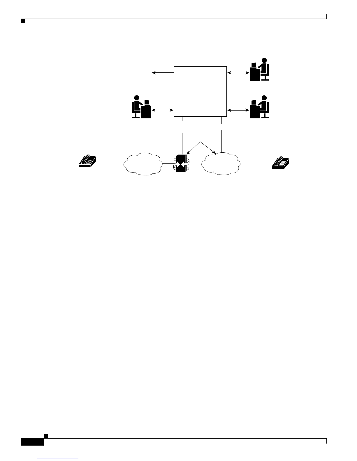
The Cisco HSI adds an H.323 interface to the Cisco Public Switched Telephone Network (PSTN)
Gateway (PGW 2200). This interface allows calls to be established between the PSTN and an H.323
network (see
The Cisco HSI provides the following services:
• Translation of signaling protocols for establishing, controlling, and releasing calls
• Administration of network parameters and protocol capabilities
• System and call-related statistics
• Fault reporting
• Overload management
• Event logging
• Simple Network Management Protocol (SNMP) interface
The Cisco HSI does not operate in an active/standby configuration and, therefore, does not provide the
same level of redundancy as the PGW 2200, which is configured as active/standby. We therefore
recommend that you use enough HSI nodes to support the number of simultaneous calls plus one. This
ensures (Trunk Group Caveats dependant) that, if one HSI fails, the calls are still adequately supported
by the remaining active HSIs.
Figure 1-1).
OL-4806-01 Rev. A14
Cisco H.323 Signaling Interface User Guide
1-1
Page 22
Cisco HSI System Description
Figure 1-1 Cisco HSI System Overview
Chapter 1 Cisco H.323 Signaling Interface Overview
Operational
support systems
PGW 2200
System
technician
System
operator
Voice/
signaling
69717
Callers
Callers
Voice/
signaling
System
administrator
Access
network
H.323 signaling
interface
E-ISUP/
RUDP
Voice
Cisco PGW 2200
H.323
IP
network
The PGW 2200 consists of the hardware and software that perform the signaling and call control tasks
(such as digit analysis, routing, and circuit selection) and seamlessly switch calls from the PSTN through
to the IP network.
IP Network
The purpose of the Cisco HSI is to enable the PGW 2200 to interoperate with the H.323 network.
Cisco HSI System Description
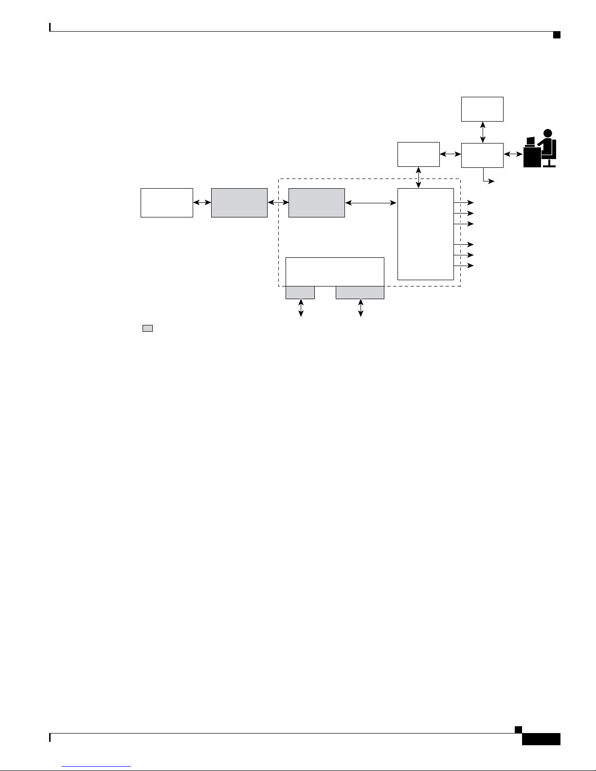
The Cisco HSI system has two subsystems (see Figure 1-2):
• Operations, Administration, and Maintenance (OAM) subsystem
• Call control subsystem
Cisco H.323 Signaling Interface User Guide
1-2
OL-4806-01 Rev. A14
Page 23
Chapter 1 Cisco H.323 Signaling Interface Overview
Figure 1-2 Cisco HSI Subsystems
Cisco HSI System Description
MML
Batch File
Workstation
OAM Subsystem
The OAM subsystem provides the following services:
• Man-Machine Language (MML) interface that enables you to retrieve operational parameters and
Process
Manager
SNMP
Third party
SNMP
Master Agent
SNMP
Subagent
Call Control
RUDP
PGW 2200
H.323 Signaling
Interface
RADVision
H.323 Signaling
interface
OAM
modify configuration values through direct input or through batch files
MML
Process
MML Log File
Alarms
Statistics
MML logfile
Provisioning files
Call trace
Logging
69718
• SNMP interface that allows statistics and alarm retrieval
• Management to provide automatic restart of the Cisco HSI application and control over the running
of the process
• Statistics, events, call trace, and alarm output to files
• Alarm events output to the MML interface
• Overload control
Call Control Subsystem
The call control subsystem provides the following services:
• Manages the Reliable User Data Protocol (RUDP) and H.323 stacks
• Implements Enhanced ISDN User Part (E-ISUP)
• Manages H.323 call control
• Performs the conversion of calls between H.323 and E-ISUP call control messages
• Provides call management and overload reduction actions
OL-4806-01 Rev. A14
Cisco H.323 Signaling Interface User Guide
1-3
Page 24

Operational Environment
RUDP
RADVision H.323
E-ISUP
Chapter 1 Cisco H.323 Signaling Interface Overview
RUDP transports the E-ISUP messages between the PGW 2200 and the Cisco HSI.
RUDP is a Cisco proprietary, connection-oriented, packet-based transport protocol.
The Cisco HSI 4.1 release uses the RADVision 4.1 H.323 stack. The HSI uses the H.225 (Q.931 and
registration, admission, and status [RAS] protocol) and H.245 protocols to implement the H.323 gateway
signaling function.
RADVision H.323 enables the creation of real-time voice H.323 calls over IP networks.
E-ISUP is a proprietary Cisco protocol based on ISUP. E-ISUP is used for inter-PGW 2200 call control.
E-ISUP uses a subset of ISUP messages. The main differences between ISUP and E-ISUP are as follows:
• E-ISUP is for the control of packet voice connection. It does not have circuit management messages
such as circuit reset and blocking.
• E-ISUP is transported over RUDP in an IP network.
• E-ISUP enables PGW 2200s to transport Session Description Protocol (SDP) information (such as
endpoint IP address and codec specifications) for call endpoints.
The Cisco HSI provides a conversion between the E-ISUP call control protocol originating from the
PGW 2200 and the H.323 call control protocol originating from the IP network (see
New Features in Cisco HSI Release 4.1
The features introduced in the Cisco HSI 4.1 release are:
• Support of H.323 Version 4
• Invocation of Empty Capabilities Set
• Notify Support
• Disk Mirroring
• Additional security features
Operational Environment
This section provides operational environment requirements for the Cisco HSI.
Figure 1-1).
Hardware Requirements
The hardware requirements for the Cisco HSI are documented in the Cisco Media Gateway Controller
Hardware Installation Guide. See the section “Cisco MGC Host Platforms” in Chapter 1.
Cisco H.323 Signaling Interface User Guide
1-4
OL-4806-01 Rev. A14
Page 25

Chapter 1 Cisco H.323 Signaling Interface Overview
Software Requirements
The software requirements for the Cisco HSI are documented in the Cisco Media Gateway Controller
Software Release 9 Installation and Configuration Guide.
Security
The application does not directly provide security features. All security must be implemented at the
UNIX level.
Cisco HSI Recovery
The Cisco HSI automatically restarts the main application process if that process terminates.
Note If the system is rebooted, the HSI is not started automatically unless the HSI was already activated prior
to the reboot.
Cisco HSI Recovery
Cisco HSI System Limitations
The Cisco HSI does not implement security features.
Note You cannot run the Cisco HSI on the same hardware platform with the Cisco PGW.
OL-4806-01 Rev. A14
Cisco H.323 Signaling Interface User Guide
1-5
Page 26

Cisco HSI System Limitations
Chapter 1 Cisco H.323 Signaling Interface Overview
Cisco H.323 Signaling Interface User Guide
1-6
OL-4806-01 Rev. A14
Page 27

Introduction
CHAPTER
2
Installing and Configuring Cisco HSI Software
This chapter contains instructions for installing and configuring the Cisco H.323 Signaling Interface
(HSI). This chapter contains the following sections:
• Hardware and Software Requirements, page 2-1
• Installing the Operating System, page 2-1
• Installing the Cisco HSI, page 2-2
• Starting the Cisco HSI, page 2-11
• Stopping the Cisco HSI, page 2-12
• Configuring the Cisco HSI, page 2-12
• Upgrading the Cisco HSI, page 2-12
• Removing the Cisco HSI, page 2-13
Hardware and Software Requirements
The hardware requirements for the Cisco HSI are documented in the Cisco Media Gateway Controller
Hardware Installation Guide. See the section “Cisco MGC Host Platforms” in Chapter 1.
The software requirements for the Cisco HSI are documented in the Cisco Media Gateway Controller
Software Release 9 Installation and Configuration Guide.
Installing the Operating System
The appropriate operating system must be installed before you install the Cisco HSI. Instructions for
installing the operating system on the appropriate platform are in the Cisco Media Gateway Controller
Software Release 9 Installation and Configuration Guide, located at the following URL:
http://www.cisco.com/univercd/cc/td/doc/product/access/sc/rel9/swinstl/index.htm
After completing the operating system installation, return to this document for Cisco HSI installation
procedures.
OL-4806-01 Rev. A14
Cisco H.323 Signaling Interface User Guide
2-1
Page 28

Installing the Cisco HSI
Installing the Cisco HSI
This section provides step-by-step instructions for installing the Cisco HSI.
Before You Start
Complete the preinstallation tasks listed in Table 2-1 before installing the Cisco HSI. Use the checklist
to ensure that each task is completed. Detailed instructions for completing some tasks follow the
checklist.
Ta b l e 2-1 Preinstallation Tasks Checklist
Check Preinstallation Task
Ensure that the required operating system is installed on the appropriate hardware platform.
Configure group and user names, as described in the “Configuring Groups and Users” section
on page 2-2.
Gather the information listed in Tab le 2-2 and note it in the table for reference during the
installation.
Have your company internal support information and Cisco support contact information
readily available so you can get help with the installation if needed. If you have questions or
need assistance, see the
Chapter 2 Installing and Configuring Cisco HSI Software
“Obtaining Technical Assistance” section on page 18.
Configuring Groups and Users
You must configure groups and users for the Cisco HSI on each host server. A user must be a member
of the “mgcgrp” group to use certain Cisco HSI functions, such as Man-Machine Language (MML).
To configure groups and users, complete the following steps:
Step 1 Log in as root.
Step 2 At the # prompt, enter the following commands:
# mkdir -p /export/home/users/mgcusr
# mkdir /export/BUILDS
# mkdir /export/PATCHES
# cd /export/home/users
# groupadd -g 20000 mgcgrp
# useradd -u 20001 -g 20000 -d /export/home/users/mgcusr -s /bin/csh mgcusr
# chown mgcusr:mgcgrp mgcusr
# passwd mgcusr <type password twice>
(Enter and confirm password)
Step 3 Log out, then log in as user mgcusr, using the password you applied in Step 2.
Step 4 Verify that you are in directory /export/home/users/mgcusr by entering the following command:
# pwd
Cisco H.323 Signaling Interface User Guide
2-2
OL-4806-01 Rev. A14
Page 29

Chapter 2 Installing and Configuring Cisco HSI Software
Step 5 Enter the following command:
# vi .cshrc
Step 6 Enter the vi insert mode by entering the following command:
i (enter insert mode)
Step 7 Enter the following text on the first line:
source /opt/GoldWing/currentPM/local/setup.gw.csh
Step 8 Save the file and quit vi by entering the following commands:
[Esc] (exit insert mode)
:wq (write file and quit)
Step 9 Enter the following command:
# chmod 777 .cshrc
Cisco HSI Installation Information
Installing the Cisco HSI
Gather the information listed in Tabl e 2-2 before you begin the Cisco HSI installation. Use the Notes
column in this table to record the information. Several steps in the installation procedure require you to
provide this information. Refer to this table as you proceed through the Cisco HSI installation steps.
Ta b l e 2-2 Cisco HSI Installation Information
Required Information Notes
Base directory path Note We strongly recommend that you accept the
default base directory path.
Cisco HSI user name Default: mgcusr
Cisco HSI group name Default: mgcgrp
Gatekeeper IP address
Gatekeeper port Default: 1719
Gateway prefix
Terminal alias
Gatekeeper ID Note This ID must match the entry configured in the
gatekeeper.
E-ISUP host port Note Typically 8003, but this entry must match the
peer port setting of the IPLNK object in the
PGW 2200 configuration.
VSC11 name (either the DNS2 host
name, if DNS is configured, or the IP
address of the Cisco PGW 22003)
VSC1 port Note Typically 8003, but this entry must match the
peer port setting of the IPLNK object in the
PGW 2200 configuration.
Installation node ID
OL-4806-01 Rev. A14
Cisco H.323 Signaling Interface User Guide
2-3
Page 30

Installing the Cisco HSI
Chapter 2 Installing and Configuring Cisco HSI Software
Table 2-2 Cisco HSI Installation Information (continued)
Required Information Notes
Hardware platform
Installation location
1. VSC = virtual switch controller
2. DNS = domain name system
3. PGW = PSTN Gateway
The Cisco HSI application is distributed as a tar file (with filename GoldWing-xxxx.tar in which xxxx is
the version ID, for example, GoldWing-4.1.tar) or as a CD-ROM.
The default installation directory is /opt/GoldWing. We recommend that you install the software at the
default location. More than one version of the software can exist within subdirectories, for example
/opt/GoldWing/4.1
Links point to the currently active version of the Cisco HSI application, as follows:
• currentPM points to the current version to use for all software except the call processing application.
• currentGW points to the version that may not be the latest version of the call processing application.
(GWmain)
Table 2-3 shows the subdirectories of the /opt/GoldWing/currentPM directory.
Ta b l e 2-3 CurrentPM Subdirectories
Subdirectory Contents
./bin All compiled executables.
./local All scripts.
./etc Base configuration files.
./lib Shared libraries required by executables.
./toolkit Toolkit files.
./var Volatile directory that contains file locks and so on.
./var/log Default log directory.
./var/prov Provision system writes provisioning config files here.
./var/trace Trace logs are written here.
Exported provisioning files are stored in /opt/GoldWing/export.
Cisco H.323 Signaling Interface User Guide
2-4
OL-4806-01 Rev. A14
Page 31

Chapter 2 Installing and Configuring Cisco HSI Software
Installing Cisco HSI
This section provides step-by-step instructions for installing a single Cisco HSI for use with a simplex
PGW 2200 configuration (a configuration with one Cisco PGW 2200 host). To install a dual Cisco HSI
for use with a redundant PGW 2200 configuration (a configuration with two Cisco PGW 2200 hosts),
complete the steps in this section and then proceed to the
PGW 2200 Configuration” section on page 2-10.
Note In the following installation procedure, the package name is OTTgw000 and the version of the software
is 4.1; the /export/BUILDS directory is used to install the system software.
To install the Cisco HSI, complete the following steps:
Step 1 Verify that the operating system is installed. See the “Installing the Operating System” section on
page 2-1 for more information.
Step 2 Login as root.
Step 3 Issue the command: cd /export
Installing the Cisco HSI
“Installing Multiple Cisco HSIs in a Redundant
Step 4 The initial step for downloading the HSI software depends upon the media from which you obtain the
software:
• If you download the software from a server, it will be in a tar file. Issue the following command:
# tar xvf GoldWing-4.1.tar
This command displays the following text:
x ./4.1/APPLICATIONS, 0 bytes, 0 tape blocks
x ./4.1/APPLICATIONS/OTTgw000.pkg, 38954496 bytes, 76083 tape blocks
x ./4.1/install.sh, 5223 bytes, 11 tape blocks
x ./4.1/uninstall.sh, 3053 bytes, 6 tape blocks
Note The byte and block counts for your installation may be different from those provided in the
preceding example.
• If you download the software from a CD-ROM, insert the Cisco HSI 4.1 CD-ROM into the drive and
issue the following commands:
# mkdir BUILDS/4.1
# cp -r /cdrom/hsi_4.1* /* /export/BUILDS/4.1
OL-4806-01 Rev. A14
Cisco H.323 Signaling Interface User Guide
2-5
Page 32

Installing the Cisco HSI
Step 5 At the # prompt, enter the following commands:
Step 6 Press Enter to select the default HSI base directory path.
Chapter 2 Installing and Configuring Cisco HSI Software
# cd /export/BUILDS/4.1
# ./install.sh
The following text displays:
Processing package instance <OTTgw000> from </export/BUILDS/4.1/APPLICATIONS/OTTgw000.pkg>
GoldWing H323 Adjunct Processor V0.1.6
(sparc) 4.1
Copyright (c) 2001 Cisco Systems, Ltd.
All Rights Reserved
This product is protected by copyright and distributed under
licenses restricting copying, distribution and decompilation.
Enter GoldWing base directory path (default /opt/GoldWing) [?,q]
Caution We strongly recommend that you select the default base directory path. Operational issues
might arise if other directories are used.
The following text displays:
Enter base directory path (default /opt/GoldWing/4.1) [?,q]
Step 7 Press Enter to select the default base directory path. The following text displays:
Enter GoldWing user name
Step 8 Type the Cisco HSI user name mgcusr and press Enter (the default user name is cisco). The following
text displays:
Enter GoldWing group name
Step 9 Type the Cisco HSI group name mgcgrp and press Enter (the default user group name is sysadmin). The
following text displays:
Enter GateKeeper IP Address
Step 10 Type the gatekeeper IP address (see Table 2-2) and press Enter. The following text displays:
Enter GateKeeper Port
Step 11 Type the gatekeeper port (see Tab le 2-2) and press Enter (the default port is 1719). The following text
displays:
Enter GateWay Prefix
Step 12 Type the gateway prefix (see Ta ble 2-2) and press Enter.
Note The gateway prefix is the prefix that, when dialed from the H.323 network, causes the Cisco HSI
to route the call over E-ISUP to the PGW 2200.
The following text displays:
Enter Terminal Alias
Step 13 Type the terminal alias (see Table 2-2) and press Enter. The following text displays:
Enter GateKeeper Id
Cisco H.323 Signaling Interface User Guide
2-6
OL-4806-01 Rev. A14
Page 33

Chapter 2 Installing and Configuring Cisco HSI Software
Step 14 Type the gatekeeper ID (see Ta b l e 2-2) and press Enter.
Note The gatekeeper ID must match the entry configured in the gatekeeper.
The following text displays:
Enter E-ISUP Host Port
Step 15 Type the E-ISUP host port (see Tab le 2-2) and press Enter.
Note The E-ISUP host port is typically 8003, but it must match the peer port setting of the IPLNK
object in the PGW 2200 configuration.
The following text displays:
Enter VSC1 Name
Step 16 Type the VSC1 name and press Enter.
Installing the Cisco HSI
Note The VSCI name is either the DNS host name (if DNS is configured) or the IP address of the
PGW 2200.
The following text displays:
Enter VSC1 Port
Step 17 Type the VSC1 port number (see Tabl e 2-2) and press Enter.
Note The VSCI port is typically 8003, but it must match the port setting of the IPLNK object in the
PGW 2200 configuration.
The following text displays:
Enter Installation NodeId
Step 18 Type the installation node ID (see Table 2-2) and press Enter.
Note The installation node ID is a text field typically used by network designers for identification
purposes. Entering a value in this field does not affect functionality.
The following text displays:
Enter Hardware Platform
Step 19 Type the hardware platform name (see Ta bl e 2-2) and press Enter (typically, accept the default platform
name). The following text displays:
Enter Installation Location
OL-4806-01 Rev. A14
Cisco H.323 Signaling Interface User Guide
2-7
Page 34

Installing the Cisco HSI
Step 20 Type the installation location (see Tab le 2-2) and press Enter.
Chapter 2 Installing and Configuring Cisco HSI Software
Note The installation location field is a text field typically used by network designers for
identification purposes. Entering a value in this field does not affect functionality.
The following is an example of the screen that displays:
## Executing checkinstall script.
Modified Environment is:
------------------------BASEDIR=/opt/GoldWing/4.1
GWHOME=/opt/GoldWing
GWUSR=mgcusr
GWGRP=mgcgrp
GWCONF_IP=”10.70.54.53”
GWCONF_PORT=”1719”
GWCONF_PREFIX=”0208”
GWCONF_ALIAS=”cisco@OuterLondonDomain.com”
GWCONF_GKID=”OuterLondon”
GWCONF_HOST_PORT=8003
GWCONF_VSC1_NAME=goliath
GWCONF_VSC1_PORT=8003
GWCONF_NODEID=”H323-GW1”
GWCONF_HARDWARE=”Sun Netra T1”
GWCONF_LOCATION=”H323 - GW1”
-------------------------
The selected base directory </opt/GoldWing/4.1> must exist before installation is
attempted.
Do you want this directory created now [y,n,?,q]
Step 21 Type y to create the version directory. The following text displays:
Using </opt/GoldWing/4.1> as the package base directory.
## Processing package information.
## Processing system information.
## Verifying disk space requirements.
## Checking for conflicts with packages already installed.
## Checking for setuid/setgid programs.
This package contains scripts which will be executed with super-user
permission during the process of installing this package.
Do you want to continue with the installation of <OTTgw000> [y,n,?]
Step 22 Review the output before you continue the installation. Type y to continue. The files are installed. The
following text displays:
Installing GoldWing H323 Adjunct Processor V0.1.6 as <OTTgw000>
## Installing part 1 of 1.
/etc/init.d/CiscoGW
/opt/GoldWing/4.1/bin/GWmain
/opt/GoldWing/4.1/bin/PMmain
/opt/GoldWing/4.1/bin/mml
/opt/GoldWing/4.1/bin/msg.conf
/opt/GoldWing/4.1/bin/parse
/opt/GoldWing/4.1/etc/GWmain.base.conf
/opt/GoldWing/4.1/etc/GWmain.default.conf
/opt/GoldWing/4.1/etc/GWmain.static.conf
/opt/GoldWing/4.1/etc/H323SkeletonFileSimple.dat
/opt/GoldWing/4.1/etc/parse.exclude.list
/opt/GoldWing/4.1/etc/parse.list
/opt/GoldWing/4.1/lib/libgwMib_shlib.so
/opt/GoldWing/4.1/var/prov/active_config <symbolic link>
[ verifying class <none> ]
Cisco H.323 Signaling Interface User Guide
2-8
OL-4806-01 Rev. A14
Page 35

Chapter 2 Installing and Configuring Cisco HSI Software
[ verifying class <script> ]
## Executing postinstall script.
Installed package instance is: OTTgw000
Installation of <OTTgw000> was successful.
Installed package instance environment variables are:
---------------------------------------------------- PKGINST=OTTgw000
VERSION=4.1
BASEDIR=/opt/GoldWing/4.1
GWHOME=/opt/GoldWing
MGCUSR=mgcusr
MGCGRP=mgcgrp
---------------------------------------------------- Setting link /opt/GoldWing/currentPM.
Setting link /opt/GoldWing/currentGW.
Installation of the Cisco HSI is now complete. The directory /opt/GoldWing now displays as follows:
drwxr-xr-x 7 cisco sysadmin 512 Jan 9 18:31 4.1
lrwxrwxrwx 1 cisco sysadmin 19 Jan 9 18:31 currentGW -> /opt/GoldWing/4.1
lrwxrwxrwx 1 cisco sysadmin 19 Jan 9 18:31 currentPM -> /opt/GoldWing/4.1
-rwxrwxr-x 1 root other 3053 Jan 9 18:31 uninstall.sh
Installing the Cisco HSI
Note The links currentPM and currentGW point to the currently active version of the Cisco HSI. The uninstall
script has been copied here for convenience, but it can be run only by root user.
To check the Cisco HSI installation, enter pkgchk OTTgw000.
Note The pkgchk command reports File size / Checksum information. This information may suggest errors
because the post-installation scripts modify some of the files with user configuration information for
which the user was prompted during the installation procedure. These messages are expected and do not
indicate a problem with the installation.
Note The package name is OTTgw000. If more than one instance of the package is installed, the package name
has a suffix (for example, OTTgw000.2, OTTgw000.3, and so on).
Outside of the /opt/GoldWing directory, the start/stop script CiscoGW is copied to the /etc/init.d
directory.
When the installation is complete, a file named PKINST is written to the base directory on the installed
software.
Caution Do not modify the PKINST file. It contains information derived from the installation, and the uninstall
script uses the PKINST file in the version directory to determine which package name to remove if more
than one instance of the package is installed.
OL-4806-01 Rev. A14
Cisco H.323 Signaling Interface User Guide
2-9
Page 36

Chapter 2 Installing and Configuring Cisco HSI Software
Installing the Cisco HSI
Installing Multiple Cisco HSIs in a Redundant PGW 2200 Configuration
This section describes how to install and configure two Cisco HSI for use with a redundant Cisco PGW
2200 configuration (See
Figure 2-1 Dual Cisco HSI with a Redundant PGW 2200 Configuration
Figure 2-1).
Cisco PGW
2200-A
194.182.147.226 194.182.147.227
194.182.147.242
Caution To ensure the successful installation of two Cisco HSIs, after Step 22 of the “Installing Cisco HSI”
194.182.147.243
Cisco PGW
2200-B
194.182.147.244
Cisco HSI-A
194.182.147.228
Cisco HSI-B
69729
section on page 2-5, provision the software for the active host first before proceeding to Step 1 below.
See “Configuring the Cisco HSI” section on page 2-12 for configuration information.
Only one active provisioning session is permitted, and provisioning is permitted only on the active
Cisco
HSI.
Exit the provisioning session on the active host and continue to Step 1 below. If software is not
provisioned after it is installed on the active host, the stand-by host is not synchronized with the active
host. As a result, a forced switchover might fail.
2-10
To install two Cisco HSIs for a redundant PGW 2200 configuration (a configuration with two
Cisco
PGW 2200 hosts), complete the following steps:
Step 1 Continuing from Step 22 of the “Installing Cisco HSI” section on page 2-5, exit server 1.
Step 2 Log in to server 2 as root and go to the # prompt.
Step 3 Insert the Cisco HSI CD-ROM in the CD-ROM drive.
Step 4 Follow the installation instructions found in Step 3 through Step 22 of the “Installing Cisco HSI” section
on page 2-5.
Installation of the dual Cisco HSI for a redundant PGW 2200 configuration is now complete. (See the
example configuration script in the following section.)
Cisco H.323 Signaling Interface User Guide
OL-4806-01 Rev. A14
Page 37

Chapter 2 Installing and Configuring Cisco HSI Software
Dual HSI Example Configuration Script
The following example script configures the network topology depicted in Figure 2-1.
Example
HSI-A (Blue network)
prov-add:name="SYS_CONFIG_STATIC",HOST_PORT_NUMBER1="9001"
prov-add:name="SYS_CONFIG_STATIC",HOST_PORT_NUMBER2="0"
prov-add:name="SYS_CONFIG_STATIC",VSCA_IPADDR1="194.182.147.242"
prov-add:name="SYS_CONFIG_STATIC",VSCA_IPADDR2="194.182.147.242"
prov-add:name="SYS_CONFIG_STATIC",VSCA_PORT_NUMBER1="8003"
prov-add:name="SYS_CONFIG_STATIC",VSCA_PORT_NUMBER2="8003"
prov-add:name="SYS_CONFIG_STATIC",VSCB_IPADDR1="194.182.147.243"
prov-add:name="SYS_CONFIG_STATIC",VSCB_IPADDR2="194.182.147.243"
prov-add:name="SYS_CONFIG_STATIC",VSCB_PORT_NUMBER1="8003"
prov-add:name="SYS_CONFIG_STATIC",VSCB_PORT_NUMBER2="8003"
HSI-B (Red network)
prov-add:name="SYS_CONFIG_STATIC",HOST_PORT_NUMBER1="9002"
prov-add:name="SYS_CONFIG_STATIC",HOST_PORT_NUMBER2="0"
prov-add:name="SYS_CONFIG_STATIC",VSCA_IPADDR1="194.182.147.226"
prov-add:name="SYS_CONFIG_STATIC",VSCA_IPADDR2="194.182.147.226"
prov-add:name="SYS_CONFIG_STATIC",VSCA_PORT_NUMBER1="8004"
prov-add:name="SYS_CONFIG_STATIC",VSCA_PORT_NUMBER2="8004"
prov-add:name="SYS_CONFIG_STATIC",VSCB_IPADDR1="194.182.147.227"
prov-add:name="SYS_CONFIG_STATIC",VSCB_IPADDR2="194.182.147.227"
prov-add:name="SYS_CONFIG_STATIC",VSCB_PORT_NUMBER1="8004"
prov-add:name="SYS_CONFIG_STATIC",VSCB_PORT_NUMBER2="8004"
Starting the Cisco HSI
Starting the Cisco HSI
To start the Cisco HSI, execute the start script as the root user and enter the following command:
# /etc/init.d/CiscoGW start
Note The application runs as root user because this is a requirement of a Simple Network Management
Protocol (SNMP) subagent application. If you do not run this script as the root user, the SNMP subagent
fails to connect to the master agent.
OL-4806-01 Rev. A14
Cisco H.323 Signaling Interface User Guide
2-11
Page 38

Stopping the Cisco HSI
Stopping the Cisco HSI
To stop the Cisco HSI, log in as root user and enter the following command:
# /etc/init.d/CiscoGW stop
Note The command to stop the Cisco HSI returns information such as the following:
/etc/init.d/CiscoGW stop
Signalling PMmain to shut down
Signalling GWmain[739] to shut down
Process 'PMmain' not found
Process 'GWmain' not found
...shutdown complete
The “not found” messages do not indicate a problem. The shutdown script first attempts to shutdown the
HSI processes gracefully (kill -39). The script then checks to determine whether the processes still exist.
If HSI processes remain active, the script uses the kill -9 command. The “shutdown complete”
announcement indicates that the shutdown script succeeded in stopping the HSI.
Chapter 2 Installing and Configuring Cisco HSI Software
Configuring the Cisco HSI
To configure the Cisco HSI, you must first access the user interface. Use the mml command (see
Appendix A, “MML User Interface and Command Reference” for more information). If the setup.gw file
has been sourced, it is in the user path. Use the provisioning commands to configure the Cisco HSI as
required (see
Command Reference” for more information).
Chapter 3, “Provisioning the Cisco HSI” and Appendix A, “MML User Interface and
Upgrading the Cisco HSI
Before removing an old version of the Cisco HSI, install the new version of the software. You can export
a provisioning session to a flat file in a format that can be used as input to another provisioning session
(see
prov-exp in Appendix A, “MML User Interface and Command Reference,” for more information).
Note To upgrade to Cisco HSI 4.1, if you have not partitioned disks according to the information provided in
the partitioning tables presented in the Cisco Media Gateway Controller Software Release 9 Installation
and Configuration Guide, you must repartition the disks and reinstall the operating system.
When you upgrade the Cisco HSI version, the following conditions apply:
• The Cisco HSI must first be stopped before installation is allowed to proceed.
• The installation of the new software does not overwrite the existing installed version.
• The installation of a new version results in a new version directory being created in the
/opt/GoldWing parent directory. The links currentPM and currentGW are updated to point to this
new version.
Cisco H.323 Signaling Interface User Guide
2-12
OL-4806-01 Rev. A14
Page 39

Chapter 2 Installing and Configuring Cisco HSI Software
• The system should be restarted to enable the re-initialization of the SNMP processes. The
craftsperson needs to change the user to root and issue the following UNIX command:
shutdown -i 6 -g 0 -y
Note To revert to a previous version of the software, manually modify the currentPM and currentGW
links in the/opt/GoldWing parent directory to point to the previous version.
The uninstall.sh script uses the PKINST file in the version directory to determine which package name
to remove.
Caution When upgrading the Cisco HSI, you must install the security package CSC0h013 before you remove
(uninstall) the preceding version of the HSI software. If you do not, the CSC0h013 security package will
not operate. This step is not required if you are performing a fresh installation of the Cisco HSI.
Removing the Cisco HSI
Removing the Cisco HSI
To remove the Cisco HSI, complete the following steps:
Step 1 Log in as root.
Step 2 Enter the following command to stop the Cisco HSI:
# /etc/init.d/CiscoGW stop
Step 3 Enter the following commands:
# cd /opt/GoldWing
# ls -l
The following is an example of the screen that displays:
drwxr-xr-x 7 cisco sysadmin 512 Jan 9 18:31 4.1
lrwxrwxrwx 1 cisco sysadmin 19 Jan 9 18:31 currentGW -> /opt/GoldWing/4.1
lrwxrwxrwx 1 cisco sysadmin 19 Jan 9 18:31 currentPM -> /opt/GoldWing/4.1
-rwxrwxr-x 1 root other 3053 Jan 9 18:31 uninstall.sh
Step 4 Enter the uninstall command and specify the version of the software that you want to uninstall, for
example:
# ./uninstall.sh 4.1
The following text displays:
Warning: This script will remove the package OTTgw000
Do you wish to proceed? [n] [y,n,?,q]
Step 5 Type y and press Enter. The following text displays:
Deleting generated files in /opt/GoldWing/4.1
The following package is currently installed:
OTTgw000 GoldWing H323 Adjunct Processor V0.1.6
(sparc) 4.1
Do you want to remove this package?
OL-4806-01 Rev. A14
Cisco H.323 Signaling Interface User Guide
2-13
Page 40

Removing the Cisco HSI
Step 6 Type y and press Enter. The following text displays:
Step 7 Type y and press Enter. The following text displays:
Chapter 2 Installing and Configuring Cisco HSI Software
## Removing installed package instance <OTTgw000>
This package contains scripts which will be executed with super-user
permission during the process of removing this package.
Do you want to continue with the removal of this package [y,n,?,q]
## Verifying package dependencies.
## Processing package information.
## Executing preremove script.
## Removing pathnames in class <script>
/opt/GoldWing/4.1/local/setup.gw
/opt/GoldWing/4.1/local/pmStart.sh
/opt/GoldWing/4.1/local/gwhalt
/opt/GoldWing/4.1/local/CiscoGW
## Removing pathnames in class <none>
/opt/GoldWing/4.1/local
/opt/GoldWing/4.1/lib/libgwMib_shlib.so
/opt/GoldWing/4.1/lib
/opt/GoldWing/4.1/etc/parse.list
/opt/GoldWing/4.1/etc/parse.exclude.list
/opt/GoldWing/4.1/etc/H323SkeletonFileSimple.dat
/opt/GoldWing/4.1/etc/GWmain.static.conf
/opt/GoldWing/4.1/etc/GWmain.request.conf
/opt/GoldWing/4.1/etc/GWmain.default.conf
/opt/GoldWing/4.1/etc/GWmain.conf
/opt/GoldWing/4.1/etc/GWmain.base.conf
/opt/GoldWing/4.1/etc
/opt/GoldWing/4.1/bin/parse
/opt/GoldWing/4.1/bin/msg.conf
/opt/GoldWing/4.1/bin/mml
/opt/GoldWing/4.1/bin/PMmain
/opt/GoldWing/4.1/bin/GWmain
/opt/GoldWing/4.1/bin
/opt/GoldWing/4.1/PKGINST
/etc/init.d/CiscoGW
/etc/init.d <shared pathname not removed>
/etc <shared pathname not removed>
## Executing postremove script.
## Updating system information.
Removal of <OTTgw000> was successful.
Cisco H.323 Signaling Interface User Guide
2-14
OL-4806-01 Rev. A14
Page 41

Provisioning the Cisco HSI
Introduction
This chapter describes the data that must be provisioned for the Cisco H.323 Signaling Interface (HSI).
The data is divided into two areas: system configuration and H.323 stack data. This chapter contains the
following sections:
• Cisco HSI Configuration, page 3-1
• H.323 Stack Configuration, page 3-10
• HSI Feature Configuration, page 3-22
Cisco HSI Configuration
All configuration data is contained within configuration files. Cisco HSI starts with an initial
configuration file in $GWHOME/currentGW/etc/GWmain.conf. This file is created during installation
of the software.
CHAPTER
3
OL-4806-01 Rev. A14
The configuration data within the file is defined as dynamic, static, or constant:
• Dynamic data can be modified by a provisioning session (see Appendix A, “MML User Interface
and Command Reference”). It can be activated on the currently running Cisco HSI.
• Static data can be modified by a provisioning session but cannot be activated on a running
Cisco
HSI. Changes to dynamic and static data can be written to a separate provisioning file (in
$GWHOME/currentGW/var/prov/configname/session.dat) that can be used during subsequent
restarts of the Cisco HSI.
• Constant configuration data is contained within the configuration file and cannot be modified by
provisioning sessions. Constant configuration data can be modified only by system technicians or
administrators who use UNIX editing tools. This data is replicated from the initial configuration file
into the provisioning files, and is included in subsequent provisioning sessions.
Examples of the use of constant data are given in Appendixes D, E, F, and G. These appendixes
determine the mapping of cause values for incoming and outgoing H.323 and Enhanced ISDN User
Part (E-ISUP) messages. System technicians can modify these values in the initial configuration file
to explicitly choose the mappings for their system.
When a provisioning session creates a new configuration file, it also verifies that provisioned data is
within allowable ranges and indicates this in the start of the file. It checksums the configuration file and
writes the checksum as $GWHOME/currentGW/var/prov/configname/checksum.dat. When the Cisco
Cisco H.323 Signaling Interface User Guide
3-1
Page 42

Cisco HSI Configuration
HSI starts up, it attempts to read the active configuration, checks that the configuration has been verified,
and ensures that the checksum matches. If the active configuration is not verified or if the checksum is
faulty, the configuration reverts to using the $GWHOME/currentGW/etc/GWmain.conf file.
All configuration data that can be set in the system is defined in the Skeleton Configuration file (see
Appendix B, “Skeleton Configuration File”). The Skeleton Configuration file defines the data names and
types (strings or numbers), and defines whether the data is dynamic, static, or constant.
MML Configuration Commands
There are three types of MML configuration command:
• Configuration session commands that work with entire provisioning data files (see Tab le 3-1)
• Configuration component or parameter commands that perform actions on components or
parameters affecting a specific data file (see
• Configuration export commands
For more information about MML configuration commands, see Appendix A, “MML User Interface and
Command Reference.”
Chapter 3 Provisioning the Cisco HSI
Table 3-2)
Note Parameter names used in MML commands are not case sensitive.
Ta b l e 3-1 Configuration Session Commands
Command Description
prov-sta Starts a provisioning session to create a new configuration or modify
an existing configuration
prov-cpy Activates the configuration settings in the current provisioning
session
prov-stp Terminates the provisioning session and saves the configuration
Ta b l e 3-2 Configuration Component or Parameter Commands
Command Description
prov-add Adds a component to the Cisco HSI
prov-dlt Deletes a provisioned component
prov-ed Modifies a provisioned component
prov-rtrv Retrieves information about an existing provisioning session
The configuration export command is prov-exp, which exports the currently provisioned configuration
of the Cisco HSI to a file.
Cisco H.323 Signaling Interface User Guide
3-2
OL-4806-01 Rev. A14
Page 43

Chapter 3 Provisioning the Cisco HSI
Introduction to MML Command Operation for HSI
After the HSI software is installed, you can configure additional items. The following MML command
examples show how to enable DTMF capability on the HSI. (For a description of the sys_config_static
entry and the dtmf parameters, please see the section (
Initiating an MML Session to Enable DTMF on the HSI
The following MML command example shows how to start an MML session and enable DTMF support
of the HSI:
Step 1 As root user, issue the following command:
/etc/init.d/CiscoGW start
Step 2 As mgcusr, begin an MML session by issuing the following command:
mml
Step 3 To enable DTMF support on the HSI, issue the following set of commands:
prov-sta:srcver=active, dstver=myconf
Cisco HSI Configuration
System Configuration Data).
Note The preceding command creates a new configuration, based on the current configuration, called
myconf.
prov-add:name=sys_config_static, dtmfsupportedtype=dtmf
prov-add:name=sys_config_static, dtmfsupporteddirection=both
prov-cpy
restart-softw
Note Certain configuration changes do not take effect until the HSI is restarted. After the
restart-softw command is issued, the HSI restarts in approximately 20 seconds.
Caution Use MML commands to perform all HSI configuration. Never manually edit system configuration files
because they do not undergo the same parse checks as MML commands. In addition, the HSI uses a
machine-generated checksum to verify the system files. If you modify the system configuration files
manually, the HSI cannot use them and reverts to the base configuration.
Verifying the Configuration
The following MML command examples show how to verify that configuration changes have been
correctly processed:
Step 1 To retrieve information about the current provisioning session, issue the following command:
prov-rtrv:list
Note The HSI prints an asterisk next to the currently active configuration.
OL-4806-01 Rev. A14
Cisco H.323 Signaling Interface User Guide
3-3
Page 44

Cisco HSI Configuration
Step 2 To display the entire configuration, issue the following command:
rtrv-config
To display a subset of the configuration, one can issue a command such as the following:
rtrv-config:sys_config_static
Step 3 To exit the MML command interpreter, issue the following command:
quit
Reverting to the Base Configuration
The following MML command examples show how to revert to the base HSI configuration:
Step 1 To begin an MML session, issue the following command:
mml
Chapter 3 Provisioning the Cisco HSI
Step 2 To revert to the base HSI configuration, issue the following command:
restart-softw:init
Note The restart-softw:init command is derived from the initial installation script. (See Step 6 in the
“Installing Cisco HSI” section on page 2-5.) To return to the configuration “myconf,” one would issue
the command restart-softw:myconf.
System Configuration Data
System configuration data can be static or dynamic. Static data can be activated only at startup. Dynamic
data can be activated during system run time.
Static System Data
To modify the static system data parameters in Table 3-3, use the sys_config_static MML name variable
for the prov-add, prov-dlt, and prov-ed commands. Stop and restart the application for the changes to
take effect.
In the following example, the prov-add command adds the static system data parameter
VSCA_PORT_NUMBER1 to a static configuration file. The prov-ed command modifies the value of
the VSCA_PORT_NUMBER1 parameter. The prov-dlt command deletes the
VSCA_PORT_NUMBER1 parameter from the static configuration file.
Example
prov-add:name=sys_config_static,vsca_port_number1=8003
prov-ed:name=sys_config_static,vsca_port_number1=8002
prov-dlt:name=sys_config_static,vsca_port_number1
The parameters in Tabl e 3-3 are written to a static configuration file or to a section within a file.
Cisco H.323 Signaling Interface User Guide
3-4
OL-4806-01 Rev. A14
Page 45

Chapter 3 Provisioning the Cisco HSI
Cisco HSI Configuration
Ta b l e 3-3 Static System Data Parameters
Parameter Ty p e Description
HOST_PORT_NUMBER1 [0-65535] The first port number to be used by the Cisco HSI. The default value is 0.
Note This value must match the peer port setting on the PGW
1
2200
E-ISUP IPLNK object.
HOST_PORT_NUMBER2 [0-65535] The second port number to be used by the Cisco HSI. The default value is 0.
Note This value should always be set to 0.
VSCA_IPADDR1 STRING The primary IP address of the primary PGW 2200.
VSCA_IPADDR2 STRING The secondary IP address of the primary PGW 2200.
Note This value must match that of VSCA_IPADDR1.
VSCB_IPADDR1 STRING The primary IP address of the secondary PGW 2200.
Note This parameter is not used in a standalone PGW configuration.
VSCB_IPADDR2 STRING The secondary IP address of the secondary PGW 2200.
Note The value of this parameter must match that of VSCB_IPADDR1.
This parameter is not used in a standalone PGW configuration.
VSCA_PORT_NUMBER1 [0-65535] The first port number of the primary PGW 2200.
VSCA_PORT_NUMBER2 [0-65535] The second port number of the primary PGW 2200.
Note This value must match that of VSCA_PORT_NUMBER1.
VSCB_PORT_NUMBER1 [0-65535] The first port number of the secondary PGW 2200.
Note This parameter is not used in a standalone PGW configuration.
VSCB_PORT_NUMBER2 [0-65535] The second port number of the secondary PGW 2200.
Note The value of this parameter must match that of
VSCA_PORT_NUMBER2. This parameter is not used in a
standalone PGW configuration.
ClipClirSupported STRING CLI Presentation or restriction is enabled if this parameter is present and set to
anything other than “”. For example, to enable CLIP/CLIR support, set this
parameter explicitly to “Enabled.”
RaiSupported STRING RAI support is enabled if this parameter is present and set to anything other than
“”. For example, to enable RAI support, set this parameter to “Enabled.”
DtmfSupportedDirection STRING This is set to “both”, “tx,” or “rx”. If this parameter is not present or is set to any
value other than “both,” “tx,” or “rx,” the DTMF Relay feature is disabled.
DtmfSupportedType STRING This is set to “dtmf” or “basicString.” If this parameter is not present or set to
any other value, the DTMF Relay feature is disabled.
H225PavoSupported STRING Pavo support is enabled if this parameter is present and set to anything other than
“”. For example, set it to “Enabled.”
PavoRedirScreeningInd [0-3] The value of the Pavo redirecting number screening indicator. (If this parameter
is not provisioned, the default is Q.931 zero—user provided, not screened.)
PavoRedirReason [0-15] The value of the Pavo redirecting number reason field. This parameter has no
default. If unprovisioned, the redirecting number parameter will not contain the
Reason for Redirection field (octet 3b).
OL-4806-01 Rev. A14
Cisco H.323 Signaling Interface User Guide
3-5
Page 46

Chapter 3 Provisioning the Cisco HSI
Cisco HSI Configuration
Table 3-3 Static System Data Parameters (continued)
Parameter Type Description
PavoRedirPresInd [0-3] The value of the Pavo redirecting number presentation indicator. (If this
parameter is not provisioned, the default is Q.931 zero—no indication.)
CliInDisplaySupported STRING If this parameter is present and set to anything other than “”, the Calling Number
is also sent in the DISPLAY IE. The NetMeeting endpoint retrieves the calling
party number from the DISPLAY IE in the H.225 setup message. To enable this
parameter, set it to “Enabled.”
T38MaxVal STRING
The T38MaxVal parameter has the following optional attributes that can be
assigned values in a specific range.
Note Values for the following attributes must be expressed in hexadecimal
format.
• MaxBit—[0x0—0xFFFFFFFF]. Specifies the maximum bit rate in units
of 100 bits per second at which a transmitter can transmit or a receiver
can receive T.38 FAX data. The default value is 0x90.
• FxMaxBuf—[0x0—0xFFFFFFFF]. Specifies the maximum buffer size
for the "t38FaxMaxBuffer" parameter for the T.38 over UDP option. The
default value is 0xc8.
• FxMaxData—[0x0—0xFFFFFFFF]. Specifies the maximum datagram
size for the "t38FaxMaxDatagram" parameter for the T.38 over UDP
option. The default value is 0x48.
T38Options STRING
This T.38 Fax parameter is assigned one of the following optional values:
• FxFillBit—[0 or 1] The default value is 0.
• FxTransMMR—[0 or 1] The default value is 0.
• FxRateTransJBIG—[0 or 1] The default value is 0.
• FXRate—[Local or Trans] The default value is Trans.
• FxUdpEC—[Red or FEC] The default value is Red.
AsymmetricHandlingSupported STRING Asymmetric Codec Treatment support is enabled if this parameter is present and
set to anything other than “”. To enable Asymmetric Codec Treatment, set this
parameter to “Enabled.”
UseConfID STRING Use this parameter to specify the precedence of extracting the Global Call ID
from the Conference ID or the GUID in the H.225 Setup message. The
provisioning of this property to a value other than “” gives precedence to the
Conference ID. For example, set it to “Enabled.” To set the precedence to the
GUID field, the crafts person can either delete the property from the config or
set it to “”.
Cisco H.323 Signaling Interface User Guide
3-6
OL-4806-01 Rev. A14
Page 47

Chapter 3 Provisioning the Cisco HSI
Cisco HSI Configuration
Table 3-3 Static System Data Parameters (continued)
Parameter Type Description
DualCLISupported STRING To enable Dual CLI support (see H.246 Annex C), set this parameter to anything
other than “”. For example, to explicitly enable Dual CLI support, set this
parameter to “Enabled.”
InjectPi8 STRING If this parameter is set to a text value (for example, “enabled” or “true”), the HSI
inserts a progress indicator value of 8 into the H.225 alerting message, which
allows creation of a backward speech path. To disable this feature, you can delete
the parameter using the command prov-dlt or issue the prov-ed command and
set the value to ““.
Note Setting the InjectPi8 parameter is required if the PSTN network does
not notify the HSI that inband information is available. For instance,
when no Optional Backward Call Indicator is present, a backward
speech path will not be available.
1. PGW = Public Switched Telephone Network (PSTN) Gateway
Changing Static System Data
To change static system data, you must first determine if it is acceptable to stop currently active calls in
20 seconds. If it is acceptable to stop active calls in 20 seconds, change static system data using the
following procedure:
Step 1 Modify the static parameters you want to change.
Step 2 Activate the changed static parameters by issuing the prov-cpy command.
Step 3 Issue the command restart-softw::confirm.
This command stops the HSI application in 20 seconds and then restarts it. The restarted HSI application
reads the changed static system data parameters.
Step 4 To ensure that traffic processing has resumed, issue the command rtrv-ne-health.
If you wish to change static system data but it is not acceptable to stop active calls in 20 seconds, use
the following procedure:
Step 1 Modify the static parameters you want to change.
Step 2 Activate the changed static parameters by issuing the prov-cpy command.
Step 3 Stop call processing by issuing the stp-callproc command, specifying the timeout period you require.
Step 4 When the timeout period expires, ensure that all traffic ceased by issuing the command rtrv-ne-health.
Step 5 Restart the HSI software by issuing the command restart-softw.
This command stops the HSI application and then restarts it. The restarted HSI application reads the
changed static system data parameters.
Step 6 To ensure that traffic processing has resumed, issue the command rtrv-ne-health.
OL-4806-01 Rev. A14
Cisco H.323 Signaling Interface User Guide
3-7
Page 48

Cisco HSI Configuration
Dynamic System Data
To modify the dynamic system data parameters in Tab le 3-4, use the sys_config_dynamic MML name
variable for the prov-add, prov-dlt, and prov-ed commands. You need not halt and restart call
processing for the changes to take effect.
In the following example, the prov-add command adds the dynamic system data parameter
OVLDLEVEL1PERCENT to a dynamic configuration file. The prov-ed command modifies the value of
the OVLDLEVEL1PERCENT parameter. The prov-dlt command deletes the OVLDLEVEL1PERCENT
parameter from the dynamic configuration file.
Example
prov-add:name=sys_config_dynamic,OVLDLEVEL1PERCENT=20
prov-ed:name=sys_config_dynamic,OVLDLEVEL1PERCENT=25
prov-dlt:name=sys_config_dynamic,OVLDLEVEL1PERCENT
The MML commands write the parameters in Tab le 3-4 to a dynamic configuration file or to a section
within a file.
Ta b l e 3-4 Dynamic System Data Parameters
Chapter 3 Provisioning the Cisco HSI
Parameter Description Default
LOGDIRECTORY Specifies the directory used when the active log file is created, and
/var/log/
also specifies the directory where the rotated log file is stored.
LOGFILENAMEPREFIX Specifies the filename prefix used when the log files are created or
platform.log
rotated. The .log postfix is appended to the end of the prefix to
establish the name of the active log file.
LOGPRIO Defines the initial logging levels. By default it is set to TRACE. When
TRACE
the system initializes and is running, the levels set for individual
packages (0x0000 to 0xFFFF) determine the log levels. See the
“Logging Levels” section on page 4-10.
LOGFILEROTATESIZE Triggers a log file rotation based on the size of the active file. The
10 Mb
application regularly checks the current size of the file to determine
whether a rotation is required. If a file rotation is triggered by this
parameter, the rotated file might be slightly larger than the size
specified by this parameter. This parameter triggers a file rotation and
also resets the timer associated with the
LOGFILEROTATEINTERVAL parameter.
LOGFILEROTATEINTERVAL Triggers a log file rotation based on the time elapsed since the
previous rotation. This timer is reset after any rotation occurs,
1440 minutes
(24 hours)
regardless of the cause or trigger of the rotation.
IPADDRNMS Defines the IP address of the network management system. —
OVLDSAMPLERATE Defines the frequency of CPU sampling and threshold checking. 3000 millisecond
(ms) polling rate
Cisco H.323 Signaling Interface User Guide
3-8
OL-4806-01 Rev. A14
Page 49

Chapter 3 Provisioning the Cisco HSI
Cisco HSI Configuration
Table 3-4 Dynamic System Data Parameters (continued)
Parameter Description Default
OVLDLEVEL1PERCENT Indicates what percentage of calls should be rejected when an
20
overload condition occurs. This parameter is used in conjunction with
the OVLDLEVEL1FILTER parameter. The overload level 1 value is
the lowest level of overload and must be less than or equal to the
provisioned values for OVLDLEVEL2PERCENT and
OVLDLEVEL3PERCENT.
Note If this value is set to zero, no overload level 1 treatment
occurs.
OVLDLEVEL1FILTER Indicates what call types should be gapped if an overload level 1
Normal
condition occurs. The possible values are:
• Normal—Emergency or priority calls are not gapped.
• All—All calls are gapped, regardless of type.
Note If the overload percentage is set to 100, all calls are gapped
irrespective of this setting.
OVLDLEVEL1THRESHLOWER
CALLS
OVLDLEVEL1THRESHUPPER
CALLS
OVLDLEVEL1THRESHLOWER
CPU
OVLDLEVEL1THRESHUPPER
CPU
OVLDLEVEL2PERCENT Indicates what percentage of calls should be rejected when an
Determines the number of active calls below which the application
load must fall in order to remove the overload level
1 condition.
Determines how many simultaneous active calls trigger an overload
level 1 condition.
Determines the CPU utilization level below which the application
must fall in order to remove the overload level 1 condition.
Determines the level of CPU utilization that triggers an overload
level
1 condition.
1800
1900
60
65
75
overload condition occurs. The parameter is used in conjunction with
the OVLDLEVEL2FILTER parameter. This is the second level of
overload and must be less than or equal to the provisioned value of
OVLDLEVEL3PERCENT and greater than or equal to the
provisioned value of OVLDLEVEL1PERCENT.
Note If this value is set to zero, no overload level 1 or 2 treatment
OVLDLEVEL2FILTER Indicates what call types should be gapped if an overload level 2
condition occurs (see OVLDLEVEL1FILTER).
OVLDLEVEL2THRESHLOWER
CALLS
Determines the number of active calls below which the application
load must fall in order for the overload level 2 condition to be
removed.
OVLDLEVEL2THRESHUPPER
CALLS
OVLDLEVEL2THRESHLOWER
CPU
OVLDLEVEL2THRESHUPPER
CPU
OL-4806-01 Rev. A14
Determines how many simultaneous active calls trigger an overload
level 2 condition.
Determines the level of CPU utilization below which the application
must fall in order for the overload level 2 condition to be removed.
Determines the level of CPU utilization that triggers an overload
level
occurs (by definition, the level 1 value must also be zero).
Normal
2000
2200
70
80
2 condition.
Cisco H.323 Signaling Interface User Guide
3-9
Page 50

Chapter 3 Provisioning the Cisco HSI
H.323 Stack Configuration
Table 3-4 Dynamic System Data Parameters (continued)
Parameter Description Default
OVLDLEVEL3PERCENT Indicates what percentage of calls should be rejected when an
overload condition occurs. The parameter is used in conjunction with
the OVLDLEVEL3FILTER parameter. This is the highest level of
overload and must be greater than or equal to the provisioned values
for OVLDLEVEL1PERCENT and OVLDLEVEL2PERCENT.
Note If this value is set to zero, no overload treatment occurs (by
definition, the level 1 and level 2 values must also be zero).
OVLDLEVEL3FILTER Indicates what call types should be gapped if an overload level 3
condition occurs (see OVLDLEVEL1FILTER).
OVLDLEVEL3THRESHLOWER
CALLS
OVLDLEVEL3THRESHUPPER
CALLS
OVLDLEVEL3THRESHLOWER
CPU
OVLDLEVEL3THRESHUPPER
CPU
CIAGENTSCANPERIOD Specifies the frequency with which the CIagent polls the CPU
ALARMDEBOUNCETIME Specifies the length of time that an alarm condition must persist
CALLREFERENCEUSAGE Determines which call reference identity is passed on to the
DISKUSAGELIMIT Represents a percentage of disk occupancy.
Determines the number of active calls below which the application
load must fall in order to remove the overload level
Determines how many simultaneous active calls trigger an overload
level 3 condition.
Determines the level of CPU utilization below which the application
must fall in order to remove the overload level 3 condition.
Determines the level of CPU utilization that triggers an overload
level
3 condition.
utilization.
before being reported, and any associated action taken.
PGW
2200 (call reference field or Conference ID).
3 condition.
90
Normal
2300
2400
85
95
—
0
—
95
The application continually polls the system for disk occupancy, and
if the percentage rises above the limit set by DISKUSAGELIMIT, the
LOW_DISK_SPACE alarm is raised.
DISKUSAGELIMIT has a default value of 95 percent. The value
range is 0–100, inclusive. When dynamically provisioned, the
parameter DISKUSAGELIMIT, if not set within that range, is set to
the default value (95) and the CONFIGURATION_ FAILURE alarm
is raised.
RegFailureReleaseCause This parameter specifies the Q.850 release cause, which the HSI uses
after the HSI fails three times to register to a gatekeeper.
This parameter is assigned a value in the range 1—127
H.323 Stack Configuration
The parameter name is based on the ASN.1 paths; but, in some cases, the parameter name has been
shortened for convenience. For example, “capabilities” has been shortened to “caps.”
The case of the parameter name reflects exactly the ASN.1 definitions; but, case is not important to
MML configuration.
Cisco H.323 Signaling Interface User Guide
3-10
—
OL-4806-01 Rev. A14
Page 51

Chapter 3 Provisioning the Cisco HSI
Nonprovisionable Data
The parameters in Tabl e 3-5 cannot be altered through MML commands.
Ta b l e 3-5 Nonprovisionable Data Parameters
H323_SYS Description
system.manualstart Present
system.pdlname Absent
system.delimiter #FF
ras.gatekeeper Absent
ras.rasmulticastaddress 224.0.1.41.1718
h245.capabilities.manualoperation Present
h245.masterslave.manualoperation Present
q931.manualaccept Present
q931.earlyH245 Present
q931.autoanswer Present
q931.manualcallprocessing Present
q931.h245tunneling Present
H.323 Stack Configuration
MML Provisionable Data
H.323 System Parameters
The parameters in Tabl e 3-6 are required for H.323 stack initialization. To modify the parameters in
Table 3-6, use the h323_sys MML name variable for the prov-add, prov-dlt, and prov-ed commands.
Stop and restart the application for these changes to take effect.
Note The asterisk (*) after a parameter name in the first column of Ta bl e 3-6 denotes a mandatory RADVision
parameter that has an inbuilt default value if a value is not set in provisioning.
Ta b l e 3-6 H.323 System Initialization Parameters
Parameter Description Ty pe Example
maxCalls* Maximum number of concurrent calls allowed INTEGER(0, 65535) 2500
maxChannels* Maximum number of concurrent channels allowed INTEGER(0, 65535) 2
Q.931 Parameters
To modify the parameters listed in Tab l e 3-7, use the q931 MML name variable for the prov-add,
prov-dlt, and prov-ed commands.
In the following example, the prov-add command sets the Q.931 parameter maxCalls to the value 2000.
OL-4806-01 Rev. A14
Cisco H.323 Signaling Interface User Guide
3-11
Page 52

H.323 Stack Configuration
Example
prov-add:name=q931,maxCalls=2000
The Update Type column in Tab le 3-7 shows when the change to a parameter takes effect once a change
is made:
• Immediate means that the effect of the change is immediate.
• Start means that the application needs to be restarted for the change to take effect.
• Next Call means that the next call has the new parameter set.
Note Immediate and Next Call update types refer to dynamic system data.
Note The asterisk (*) after a parameter name in the first column of Ta bl e 3-7 denotes a mandatory RADVision
parameter with an inbuilt default value that will be used if the value is not set in provisioning.
Ta b l e 3-7 Q.931 Parameters
Chapter 3 Provisioning the Cisco HSI
Parameter Name Description Ty pe Example Update Type
responseTimeOut* The maximum time (in seconds) permitted
INTEGER(1,200) 20 Immediate
to receive the first response to a call. If this
parameter expires, the call is disconnected.
connectTimeOut* The maximum time (in seconds) the stack
INTEGER(1,20000) 180 Immediate
waits for call establishment after the first
response is received. If this parameter
expires, the call is disconnected.
callSignalingPort* The number of the port receiving the calls
INTEGER(0,65535) 1720 Start
destined for the PGW 2200.
maxCalls* The maximum number of simultaneous
INTEGER(0,65535) 2500 Next Call
calls permitted. If this parameter is
exceeded, the next call attempt returns busy.
notEstablishControl The stack does not allow the switching of
NULL Not present Next Call
control from the Q.931 to the H.245 stack.
overlappedSending Because the Q.931 configuration flag
NULL Present Immediate
indicates that both parties support overlap
sending, this state notifies the other party
that it can send an overlap sending message.
Note The Q.931 parameter overlappedSending has been combined with the RAS overlappedSending
parameter. If you set the Q.931 overlappedSending parameter, you also set the RAS overlappedSending
parameter.
Cisco H.323 Signaling Interface User Guide
3-12
OL-4806-01 Rev. A14
Page 53

Chapter 3 Provisioning the Cisco HSI
RAS Parameters
The parameters in Tabl e 3-8 are required for RAS stack initialization. To modify the RAS parameters,
use the ras MML name variable for the prov-add, prov-dlt, and prov-ed commands.
In the following example, the prov-add command sets the RAS parameter maxfail to the value 3.
Example
prov-add:name=ras,maxfail=3
The array index [i] in some of the parameter names in the first column of Table 3-8 must be replaced
with a valid braced index from 1 to 20, and must be continuous and unique (that is, it must contain no
duplicates).
The Update Type column in Table 3-8 shows when the change to a parameter takes effect after it is
modified:
• Immediate means that the effect of the change is immediate.
• Start means that the application needs to be restarted for the change to take effect.
• Next Call means that the next call has the new parameter set.
H.323 Stack Configuration
Note Immediate and next call update types are dynamic system data.
Note The RAS parameter overlappedSending is not available here because it has been combined with the
Q.931 overlappedSending parameter. If you set the Q.931 overlappedSending parameter, you also set the
the RAS overlappedSending parameter.
Note The asterisk (*) after a parameter name in the first column of Ta bl e 3-8 denotes a mandatory RADVision
parameter with an inbuilt default value that will be used if the value is not set in provisioning.
Ta b l e 3-8 RAS Parameters
Parameter Name Description Ty pe Example Update Type
manualRAS If this parameter is present,
NULL — Start
the stack does not perform
automatic RAS procedures
(it waits to be driven by the
application).
responseTimeOut* The time (in seconds) that
INTEGER(1, 200) 10 Immediate
the stack waits until it
notifies the application that
the called party has failed to
respond to a transaction.
maxFail* Maximum number of retry
INTEGER(1, 200) 3 Immediate
gatekeeper registration
attempts.
OL-4806-01 Rev. A14
Cisco H.323 Signaling Interface User Guide
3-13
Page 54

Chapter 3 Provisioning the Cisco HSI
H.323 Stack Configuration
Table 3-8 RAS Parameters (continued)
Parameter Name Description Type Example Update Type
allowCallsWhenNonReg If this parameter is present, it
NULL Not present Immediate
allows calls to proceed even
if gatekeeper registration has
not been done for the
PGW
2200.
manualRegistration If this parameter is present,
NULL Not present Stop/Start
the stack does not perform
automatic gatekeeper
registration procedures (it
waits to be driven by the
application).
timeToLive The maximum time (in
INTEGER(1, 65535) 400 Immediate
seconds) that the registration
of the PGW 2200 with a
gatekeeper remains valid.
The stack reregisters
periodically.
rasPort* The number of the port
INTEGER(0, 65535) 0 Start
receiving all RAS
transactions for the current
endpoint. Set this parameter
to 0 to allow the software to
look for the available port.
compare15bitRasCrv If this parameter is present, it
NULL — Immediate
causes the stack to ignore the
call reference value (CRV)
MSBit in RAS messages.
maxRetries* Maximum number of RAS
INTEGER(1, 200) 3 Immediate
retransmissions.
maxMulticastTTL Maximum number of
INTEGER(0, 200) 3 Start
multicast time to live (TTL).
preGrantedArqUse Choice of direct or routed. If
STRING direct Next Call
direct, the pregranted
Admission Request (ARQ)
feature is used for both direct
and routed calls. If routed,
the pregranted ARQ feature
is used only for routed calls.
If absent, the pregranted
ARQ is not used.
manualDiscovery.ipAddress The IP address of a known
STRING 10.70.54.53 Start
gatekeeper with which an
endpoint might attempt to
register.
Cisco H.323 Signaling Interface User Guide
3-14
OL-4806-01 Rev. A14
Page 55

Chapter 3 Provisioning the Cisco HSI
H.323 Stack Configuration
Table 3-8 RAS Parameters (continued)
Parameter Name Description Type Example Update Type
manualDiscovery.port The port associated with the
INTEGER(0, 65535) 1719 Start
manualDiscovery.ipAddress,
which can, by agreement, be
either a well-known port or
another port.
gateway.prefix[i] The gateway registers the
STRING 0208 Immediate
telephone prefix specified by
this parameter to indicate
that it is able to terminate it.
gatekeeperId Identifies the gatekeeper
STRING OuterLondon Immediate
with which the endpoint is
trying to register.
terminalAlias[i].e164 Two variants of the same
terminalAlias[i].h323ID STRING GW@ot.com.au Immediate
address for the endpoint;
e164 is numeric and h323ID
STRING 0208001000 Immediate
is text.
endpointVendor.t35CountryCode These parameters identify
endpointVendor.t35Extension INTEGER(0, 255) 11 Immediate
the manufacturer of the
endpoint.
INTEGER(0, 255) 11 Immediate
endpointVendor.manufacturerCode INTEGER(0, 65535) 9 Immediate
endpointVendor.productId Data that the manufacturer
STRING H323ESP Immediate
assigns to each product.
endpointVendor.versionId Data that the manufacturer
STRING R0.2.4 Immediate
assigns to each version.
H.245 Parameters
Note Immediate and Next Call update types are dynamic system data.
OL-4806-01 Rev. A14
To modify the H.245 parameters listed in Table 3-9, use the h245 MML name variable for the prov-add,
prov-dlt and prov-ed commands.
In the following example, the prov-add command sets the H.245 parameter masterSlave.timeout to the
value 5.
Example
prov-add:name=h245,masterSlave.timeout=5
The Update Type column in Table 3-9 shows when a change to an H.245 parameter takes effect after it
is modified:
• Immediate means that the effect of the change is immediate.
• Start means that the application needs to be restarted for the change to take effect.
• Next Call means that the next call has the new parameter set.
Cisco H.323 Signaling Interface User Guide
3-15
Page 56

Chapter 3 Provisioning the Cisco HSI
H.323 Stack Configuration
Ta b l e 3-9 H.245 Parameters
Parameter Name Description Ty pe Example
masterSlave.terminalType The terminal type for the
PGW
2200.
masterSlave.manualResponse If this parameter is present, it
INTEGER(0, 255) 60 Next Call
NULL Present Next Call
cancels automatic
acknowledgment of master or slave
determination.
masterSlave.timeout The maximum time (in seconds)
INTEGER(0, 65535) 5 Immediate
the stack waits before it gives up on
the master/slave procedure.
channelsTimeout The time (in seconds) the stack
INTEGER(0, 65535) 10 Immediate
waits for a response to a channel
establishment message.
roundTripTimeout The time (in seconds) the stack
INTEGER(0, 65535) 5 Immediate
waits for round-trip procedure
completion.
requestCloseTimeout The time (in seconds) the stack
INTEGER(0, 65535) 5 Immediate
waits for request close procedure
completion.
requestModeTimeout The time (in seconds) the stack
INTEGER(0, 65535) 5 Immediate
waits for request mode procedure
completion.
caps.timeout The maximum time (in seconds)
INTEGER(0, 65535) 5 Immediate
the stack waits before it gives up on
the capability exchange procedure.
caps.maxAudioDelay Maximum H.255 multiplex audio
INTEGER(0, 1023) 60 Immediate
delay jitter.
mediaLoopTimeout The timeout (in seconds) of the
INTEGER(0, 65535) 5 Immediate
media loop procedure.
Update
Ty pe
Table 3-10, Table 3-11, and Tab l e 3-12 list the parameters and modes related to the configuring of
codecs. The array index [i] must be replaced with a valid braced index from 1 to 20. The braced index
must be continuous and unique (that is, there must be no duplicates).
Ta b l e 3-10 H.245 Terminal Capability Codec Parameters
Parameter Name Ty pe
caps.table[i].entryNo INTEGER(1, 65535)
caps.table[i].audio.g711Alaw64k INTEGER(1, 256)
caps.table[i].audio.g711Alaw56k INTEGER(1, 256)
caps.table[i].audio.g711Ulaw64k INTEGER(1, 256)
caps.table[i].audio.g711Ulaw56k INTEGER(1, 256)
caps.table[i].audio.g722at64k INTEGER(1, 256)
Cisco H.323 Signaling Interface User Guide
3-16
OL-4806-01 Rev. A14
Page 57

Chapter 3 Provisioning the Cisco HSI
Table 3-10 H.245 Terminal Capability Codec Parameters (continued)
Parameter Name Type
caps.table[i].audio.g722at56k INTEGER(1, 256)
caps.table[i].audio.g722at48k INTEGER(1, 256)
caps.table[i].audio.g7231.maxAudioFrames INTEGER(1,256)
caps.table[i].audio.g7231.silenceSuppression INTEGER(0,1)
caps.table[i].audio.g728 INTEGER(1, 256)
caps.table[i].audio.g729 INTEGER(1, 256)
Ta b l e 3-11 H.245 Channel Codec Parameters
Parameter Name Ty pe
chan[i].name STRING
chan[i].audio.g711Alaw64k INTEGER(1, 256)
chan[i].audio.g711Alaw56k INTEGER(1, 256)
chan[i].audio.g711Ulaw64k INTEGER(1, 256)
chan[i].audio.g711Ulaw56k INTEGER(1, 256)
chan[i].audio.g722at64k INTEGER(1, 256)
chan[i].audio.g722at56k INTEGER(1, 256)
chan[i].audio.g722at48k INTEGER(1, 256)
chan[i].audio.g7231.maxAudioFrames INTEGER(1,256)
chan[i].audio.g7231.silenceSuppression INTEGER(0,1)
chan[i].audio.g728 INTEGER(1, 256)
chan[i].audio.g729 INTEGER(1, 256)
H.323 Stack Configuration
Ta b l e 3-12 H.245 Modes
Parameter Name Typ e
modes[i].name STRING
modes[i].audio.g711Alaw64k NULL
modes[i].audio.g711Alaw56k NULL
modes[i].audio.g711Ulaw64k NULL
modes[i].audio.g711Ulaw56k NULL
modes[i].audio.g722at64k NULL
modes[i].audio.g722at56k NULL
modes[i].audio.g722at48k NULL
modes[i].audio.g7231 INTEGER(1,256)
modes[i].audio.g728 NULL
modes[i].audio.g729 NULL
OL-4806-01 Rev. A14
Cisco H.323 Signaling Interface User Guide
3-17
Page 58

H.323 Stack Configuration
Codec Selection
The Cisco HSI negotiates the media stream codec to establish a match between the PSTN MGCP media
gateway (for example, the Cisco AS5xxx series or Cisco MGX series) and the H.323 endpoint or
gateway. To match codecs, the MGCP gateway must be configured to match what is expected at the
H.323 end. Similarly, the Cisco HSI also must be configured with the same codecs.
The Cisco HSI receives a list of codecs from the MGCP gateway and matches the listed codecs to the
codecs that are configured on the HSI. The HSI advertises all of the successful matches in the H.245
terminalCapabilitySet messaging with the H.323 endpoint.
It is important to determine and configure the “frames-per-packet” value correctly on the Cisco HSI per
codec. If “frames-per-packet” value is incorrect, the codec may not be negotiated successfully between
the HSI and the H.323 endpoint.
It is also important to configure the MGCP gateway correctly. The gateway should be configured to
provide “static payload” values for the required codecs, rather than dynamic payload types (see Table 4
in RFC 3551, Schulzrinne and Casner).
Quick Reference for Important Parameters
Chapter 3 Provisioning the Cisco HSI
Table 3-13, Tab le 3-14, Table 3-15, and Tabl e 3-16 can be used in initial HSI configuration. The tables
present parameters that you might use frequently to align the Cisco HSI with an existing PSTN or Voice
over IP network.
Table 3-13 presents important call control parameters.
Ta b l e 3-13 Common Call Control Parameters
Parameter Name Parameter Value Description
A_CC_oLinecall 0—Unknown
Calling party's category
10—Ordinary
A_CC_Clir 0—No indication
Address presentation restricted indicator
1—Presentation allowed
2—Presentation restricted
3—Address not available
A_CC_ANumDataSI 0—None
Screening indicator
1—User provided not verified
2—User provided verified passed
3—User provided verified failed
4—Network provided
A_CC_oIsdnAllTheWay 0—ISDN user part not used all the way
Forward call indicator, ISUP indicator
1—ISDN user part used all the way
A_CC_oIsdnPref 0—ISDN user part preferred all the way
1—ISDN user part not required all the
way
2—ISDN user part required all the way
Cisco H.323 Signaling Interface User Guide
3-18
Forward call indicator, ISUP preference
OL-4806-01 Rev. A14
Page 59

Chapter 3 Provisioning the Cisco HSI
Table 3-13 Common Call Control Parameters (continued)
Parameter Name Parameter Value Description
A_CC_Interworking 0—No interworking encountered (SS7 all
Backward call indicator, Interworking indicator
the way)
1—Interworking encountered
A_CC_Location 1—User
Cause indicator, Location
2—Private local
3—Public local
4—Transit
5—Public remote
6—Private remote
7—International
8—Interworking
9—Local interface
H.323 Stack Configuration
11—Local remote
12—Packet manager
13—Unknown
The following MML command example shows the command sequence used to provision the call control
parameters provided in the preceding table.
Example
mml
> prov-sta::srcver=active, dstver=myconf
> prov-ed:name=CCPackage, A_CC_ANumDataSI=2
> prov-cpy
> restart-softw
Table 3-14 presents important static system data parameters.
OL-4806-01 Rev. A14
Cisco H.323 Signaling Interface User Guide
3-19
Page 60

H.323 Stack Configuration
Ta b l e 3-14 Common Static System Data Parameters
Parameter Name Parameter Values Description
CarrierCodeMapping • “enabled”—a string that indicates the
feature is enabled.
• Blank (“”)—indicates the feature is
disabled.
• “deleted”—indicates that the feature
Allows the mapping of a special tech prefix (the
format of which is CCxCy) to the
DestinationCircuitID “group” field in the ARQ
message. This feature works only with IOS
Gatekeeper build Release 12.2(15)T10 or above.
is disabled.
ClipClirSupported • “enabled”—a string that indicates the
feature is enabled.
Allows transit of CLI presentation/screening
information.
Chapter 3 Provisioning the Cisco HSI
• Blank (“”)—indicates the feature is
disabled
• “deleted”—indicates that the feature
is disabled
DtmfSupportedType • “dtmf”—the recommended value for
interworking with Cisco gateways
• “basicString”
DtmfSupportedDirection • “tx”—transmit to H323 endpoint
• “rx”—receive from H.323 endpoint
• “both”—transmit and receive DTMF
• Blank (“”), “deleted,” or any other
string, such as “disabled”—indicates
the feature is disabled
H225PavoSupported • “enabled”—a string that indicates the
feature is enabled.
• Blank (“”)—indicates the feature is
disabled
• “deleted”—indicates that the feature
is disabled
RaiSupported For example:
• “enabled”—a string that indicates the
feature is enabled.
• Blank (“”)—indicates the feature is
disabled
Note Setting this parameter to “enabled”
enables use of Caller ID.
Selects the DTMF type during H.245 terminal
capabilities exchange.
Note Set this parameter to “dtmf” and the
DtmfSupportedDirection parameter to
“both” to enable DTMF support.
Selects DTMF transit direction.
Note Set this parameter to “both” and the
DtmfSupportedType parameter to “dtmf”
to enable DTMF support.
Allows transit of redirecting number parameter
(contained in Cisco CallManager H.225 setup
messages—nonStandardControl field).
Allows H.225 RAS RAI messages to be sent to the
gatekeeper if the E-ISUP link fails or if the HSI is
under heavy load.
Note Set this parameter to “enabled” to enable
the HSI to support RAI messages.
• “deleted”—indicates that the feature
is disabled
Cisco H.323 Signaling Interface User Guide
3-20
OL-4806-01 Rev. A14
Page 61

Chapter 3 Provisioning the Cisco HSI
H.323 Stack Configuration
Table 3-14 Common Static System Data Parameters (continued)
Parameter Name Parameter Values Description
NotifyMsgEnabled For example:
• “enabled”—a string that indicates the
feature is enabled.
• Blank (“”)—indicates the feature is
Allows transit of connected number, display
information, and generic notification indicator in
H.225 Notify messages.
disabled
• “deleted”—indicates that the feature
is disabled
VSCB_IPADDR1/2 IP address, for example: “10.10.10.1” Allows IP address configuration of second PGW.
VSCB_PORT_NUMBER1/2 Port number, for example: 8003 Allows port configuration of second PGW.
The following MML command example shows the command sequence used to provision the static
system data parameters provided in the preceding table.
Example
mml
> prov-sta::srcver=active, dstver=myconf
> prov-ed:name=SYS_CONFIG_STATIC, DtmfSupportedType=”dtmf”
> prov-cpy
> restart-softw
Table 3-15 presents common RAS parameters.
Ta b l e 3-15 Common RAS Parameters
Parameter Name Parameter Value Description
gateway.prefix[1]
For example: 020 HSI prefix (for gatekeeper registration)
gateway.prefix[2]
timeToLive Integer (to specify number of seconds)
for example, 45
Note To enable lightweight RRQs, the
RAS registration time to live.
See Tab le 3-8.
value for this parameter should be
set substantially lower than the
default (600).
The following MML command example shows the command sequence used to provision the RAS
parameters provided in the preceding table.
Example
mml
> prov-sta::srcver=active, dstver=myconf
> prov-ed:name=RAS, timeToLive=45
> prov-cpy
> restart-softw
OL-4806-01 Rev. A14
Cisco H.323 Signaling Interface User Guide
3-21
Page 62

HSI Feature Configuration
Chapter 3 Provisioning the Cisco HSI
Table 3-16 presents common H.245 parameters for enabling the G.729 codec.
Ta b l e 3-16 Common H.245 Parameters
Parameter Name Parameter Value
chan[i].name For example:
prov-add:name=”H245”,chan[4].name=”g729”
chan[i].audio.g729 For example:
prov-add:name=”H245”,chan[4].audio.g729=”2”
caps.table[i].audio.g729 For example:
prov-add:name=”H245”,caps.table[4].audio.g729=”2”
caps.table[i].entryNo For example:
prov-add:name=”H245”,caps.table[4].entryno=”729”
modes[i].name For example:
prov-add:name=”H245”,modes[3].name=”g729”
modes[i].audio.g729 For example:
The following MML command example shows the command sequence used to provision the H.245
parameters provided in the preceding table for enabling the G.729 codec. Provisioning the G.729 codec
on the Cisco HSI supports passing SS7 calls to the Cisco CallManager through a gateway running the
Media Gateway Control Protocol (MGCP).
Example
prov-sta::srcver=”active”,dstver=”g729"
prov-add:name=”H245”,caps.table[4].audio.g729=”2”
prov-add:name=”H245”,caps.table[4].entryno=”729”
prov-add:name=”H245”,chan[4].audio.g729=”2”
prov-add:name=”H245”,chan[4].name=”g729”
prov-add:name="H245",modes[3].audio.g729=""
prov-add:name=”H245”,modes[3].name=”g729”
HSI Feature Configuration
This section describes how to enable the following HSI features:
• Asymmetric Codec Treatment
• Empty Capability Set
prov-add:name=”H245”,modes[3].audio.g729=”3].audio.
g729=””
• H.323 Hairpin
• T.38 Fax
• HSI INFORMATION Message Support
• HSI Support for Tech Prefixes
• Configuring Clear Channel on the Cisco HSI
Cisco H.323 Signaling Interface User Guide
3-22
OL-4806-01 Rev. A14
Page 63

Chapter 3 Provisioning the Cisco HSI
• Configuring G.726 on the Cisco HSI
• Configuring G.729 Annex and G.729 Annex B
Asymmetric Codec Treatment
The Asymmetric Codec Treatment feature averts the potential for inconsistencies in codec selection,
which can result if the open channel requests are sent by each endpoint at nearly the same time, so that
neither side has received an open channel request prior to sending one. In practice, such asymmetric
conditions occur only for slow start calls. When there is a fast start recipient, both channels agree to use
the same codec in unison.
The Asymmetric Codec Treatment support is enabled if this parameter is present and set to anything
other than “”. For example, support is enabled if the parameter is explicitly set to “Enabled.” To enable
Asymmetric Codec Treatment, enter the following command:
Example:
prov-add:name=sys_config_static, asymmetrichandlingsupported = "Enabled"
HSI Feature Configuration
Empty Capability Set
The Empty Capability Set feature enables an H.323 endpoint to send a TCS message with empty
capabilities during a call. The TCS message causes the audio channels to close. This action enables the
negotiation and opening of new audio channels.
The Empty Capability Set feature is useful when the H.323 endpoint wishes to change the audio codec
during a call or if the endpoint needs to divert the media streams to a different location. Typically, the
feature is used to place a call on hold to disable the media stream until the user presses the Resume
button.
The Empty Capability Set feature on the HSI requires no provisioning.
H.323 Hairpin
The H.323 Hairpin feature can be used to connect a call between two H.323 endpoints without using
resources on the media gateway. For example, the PGW can respond to the dialled number in an
incoming H.323 call by routing the call to another HSI (perhaps the same HSI) rather than routing the
call to the PSTN. In this case, the originating and terminating HSIs establish the call normally but pass
the H.245 address of the H.323 endpoints. This enables the two endpoints to use H.245 to negotiate
media channels with each other directly, independent of the HSI.
The H.323 Hairpin feature on the HSI requires no provisioning. However, to operate throughout the
system, H.323 Hairpin must be enabled on the PGW. On the PGW, you enable H.323 Hairpin through a
trunk group property by issuing the following commands:
prov-add:trnkgrpprop:name="2000",AllowH323Hairpin="1"
prov-add:trnkgrpprop:name="3000",AllowH323Hairpin="1"
Note H.323 Hairpin must be enabled for both the ingress and egress EISUP trunk groups.
OL-4806-01 Rev. A14
Cisco H.323 Signaling Interface User Guide
3-23
Page 64

HSI Feature Configuration
T.38 Fax
Chapter 3 Provisioning the Cisco HSI
Refer to Cisco PGW and Cisco IOS documentation at www.cisco.com for further information on these
commands.
The T.38 Fax feature enables the HSI to alter a call, initially established for voice, to support a fax
transmission.
When a fax call is initiated, a voice call is established. When the terminating gateway detects the fax
tone generated by the terminating fax machine, the gateway initiates a T.38 mode request using H.245
procedures from the terminating gateway. If the opposite end of the call acknowledges the T.38 mode
request, the initial audio channel is closed and a T.38 fax relay channel is opened.
You enable T.38 Fax for the HSI by specifying static system data parameters. By default, T.38 is
provisioned on the HSI by use of the following commands:
prov-add:name=sys_config_static,t38maxval="MaxBit 0x90, FxMaxBuf 0xc8, FxMaxData 0x48"
prov-add:name=sys_config_static,t38options="FxFillBit 0, FxTransMMR 0, FxTransJBIG 0,
FxRate Trans, FxUdpEC Red"
Table 3-3 describes the T.38 static system data parameters. The T.38 parameters for HSI correspond to
T.38 parameters proposed in the ITU T.38 recommendation.
Configuring T.38 Fax on the Cisco PSTN Gateway
To enable T.38 Fax throughout the system, you must enable T.38 Fax on the Cisco PGW. On the PGW,
T.38 is enabled through a trunk group property by use of the following MML command:
prov-add:trnkgrpprop:name="2000",FaxSupport="1"
Configuring T.38 Fax on a Cisco IOS H.323 Gateway
Enable T.38 Fax on a Cisco IOS H.323 gateway by issuing the following IOS commands:
voice service voip
fax protocol t38 ls-redundancy 0 hs-redundancy 0 fallback none
Configuring T.38 Fax on a Cisco IOS MGCP Gateway
Enable T.38 fax on a Cisco IOS MGCP gateway by issuing the following IOS commands:
voice service voip
fax protocol t38 ls-redundancy 0 hs-redundancy 0 fallback none
mgcp package-capability fxr-package
Refer to PGW and Cisco IOS documentation at www.cisco.com for further information on these
commands.
HSI INFORMATION Message Support
Cisco CallManager uses the H.225 INFORMATION message during transfer to indicate that ringback
tone is on or off. The Cisco HSI now supports this message to correctly interoperate with Cisco
CallManager.
Cisco H.323 Signaling Interface User Guide
3-24
OL-4806-01 Rev. A14
Page 65

Chapter 3 Provisioning the Cisco HSI
Support for the H.225 INFORMATION message is enabled by default. A crafts person can disable H.255
INFORMATION message support through a new property called Information MsgDisabled by issuing
the following MML command:
prov-add:name=sys_config_static,informationmsgdisabled = "True"
HSI Support for Tech Prefixes
The Cisco HSI now maps the '*' (asterisk, or star) and '#' (number sign, or hash) H.225 prefixes to the
PGW for H.323 to PSTN calls as follows:
• '*' to the value provisioned in ccpackage.Star
• '#' to the value provisioned in ccpackage.Hash
• The current value for ccpackage.Star is 'B'.
• The current value for ccpackage.Hash is 'A'.
The crafts person can change these values by issuing the following MML command:
prov-ed:name=ccpackage,hash='C'
HSI Feature Configuration
Cisco HSI now maps the EISUP 'B' to '*' and 'C' to '#' (Called Party Number) for PSTN to H.323 calls.
Configuring Clear Channel on the Cisco HSI
The Clear Channel capability (identified as G.Clear or gclear in this document) enables support for both
voice and data calls on a network. However, the end applications are responsible for packet loss and error
recovery. For more information, refer to the document G.Clear, GSMFR, and G.726 Codecs and Modem
and Fax Passthrough for Cisco Universal Gateways at
http://www.cisco.com/en/US/products/sw/iosswrel/ps1839/products_feature_guide09186a00800b3568
.html.
Note In association with the Cisco HSI, the Cisco PGW must be running 9.5(2) patch set gs034/nn028, or
later, to use G.Clear.
The Cisco HSI interoperates with Cisco voice gateways (for example, the Cisco AS54xx series or
VISM), which advertises G.Clear capability via MGCP signaling using the following methods: G.Clear,
G.nX64, CCD. The Cisco HSI automatically selects the correct method depending on the gateway that
originates or terminates the call.
Refer to the Cisco H.323 Signaling Interface User Guide for information regarding the use of HSI MML
commands.
OL-4806-01 Rev. A14
Cisco H.323 Signaling Interface User Guide
3-25
Page 66

HSI Feature Configuration
Table 3-17 presents examples of configuration commands that may be required to implement a particular
G.Clear configuration.
Ta b l e 3-17 Configuring Clear Channel
Clear Channel Parameters Example Value Example Configuration
H245, caps.table[i].audio.gclear “ClearChid”
prov-add:name=h245, caps.table[9].audio.gclear="ClearChid"
Chapter 3 Provisioning the Cisco HSI
Note The string
prov-add:name=h245, caps.table[10].audio.gclear="ClearChid"
“ClearChid” is
case-sensitive;
it must be
entered exactly
as displayed in
all command
examples in this
table.
H245,
caps.table[i].audio.entryNo
1010, 1011, 1012…
Note This parameter
prov-add:name=h245, caps.table[9].entryNo=1010
prov-add:name=h245, caps.table[10].entryNo=1011
should be set to
a unique integer
value.
H245, chan[i].audio.gclear “ClearChid” prov-add:name=h245, chan[9].audio.gclear=ClearChid"
prov-add:name=h245, chan[10].audio.gclear="ClearChid"
H245, chan[i].name “ClearChid” prov-add:name=h245, chan[9].name="ClearChid"
prov-add:name=h245, chan[10].name="ClearChid"
H245, modes[i].audio.gclear “ClearChid” prov-add:name=h245, modes[9].audio.gclear="ClearChid"
prov-add:name=h245, modes[10].audio.gclear="ClearChid"
H245, modes[i].name “ClearChid” prov-add:name=h245, modes[9].name="ClearChid"
3-26
prov-add:name=h245, modes[10].name="ClearChid"
Cisco H.323 Signaling Interface User Guide
OL-4806-01 Rev. A14
Page 67

Chapter 3 Provisioning the Cisco HSI
Configuring G.726 on the Cisco HSI
The G.726 codec enables transcoding a PCM channel to or from an ADPCM data stream. The standard
supports four data rates:16, 24, 32 and 40 kbit/sec.
G.726 capability is advertised by the Cisco HSI and other H.323 gateways/endpoints in H.225 fast-start
elements, in H.245 (tunneled or a separate TCP/IP connection) terminal capability (TCS) messages, and
open logical channel (OLC) messages.
Currently, H.323 devices use several different methods to advertise G.726. ITU G.726 Annex B defines
one method, referred to in this document as g726-generic. Cisco H.323 gateways (for example, the Cisco
AS5400) support an alternate method referred to as g726-cisco. There is another method used by the
OpenH323 project; however, the Cisco HSI does not support that method.
MGCP gateways advertise G.726 capability using the method described in RFC 3551 (RTP Profile for
Audio and Video Conferences with Minimal Control). The four data rates use dynamic payloads;
however, the 32kbit/sec data rate, alternatively, can have a static payload value of 2 (this alternative value
is being phased out).
You can configure the Cisco HSI for 32kbit/sec MGCP support using dynamic or static payload values.
In addition, you can configure the Cisco HSI to support g726-generic and/or g726-cisco for the H.323
signaling. If possible, it is best to select g726-cisco for your network because it offers additional
flexibility.
HSI Feature Configuration
The g726-generic method cannot indicate the data rate in H.245 TCS messages. The ITU standard
specifies that the data rate is only advertised in the OLC messages.
Note The H.245 ASN.1 syntax supports advertising the bitrate in TCS messages; however, G.726 Annex B
prohibits advertising the bitrate in TCS messages. The Cisco HSI advertises the bitrate in the TCS
messages as a “hint”; however, H.323 gateways/endpoints might not extract the field and take advantage
of the presence of the bitrate in the TCS message.
The fact that the g726-generic method cannot indicate the data rate in an H.245 TCS message is not a
problem if the MGCP gateway and your network are designed to support all data rates for this codec.
However, if all data rates are not supported, it is possible for the remote endpoint/gateway to select a
non-preferred or non-supported data rate in the OLC message.
Note For example, a data-rate preference list may establish the following order: G.726-16kbit/sec (highest
preference), G.711-Alaw (second preference), G.726-24kbit/sec (lowest preference). In this case, a
remote endpoint could select G.726-24kbit/sec in the OLC message; whereas, the Cisco HSI would
prefer G.726-16kbit/sec. In this example, the next preferred codec ought to be G.711 A-law and not
G.726-24kbit/sec. However, the g726-generic limitation enables the remote endpoint to select the least
preferred codec.
If a data-rate preference list specifies only a single rate (for example, G.726-16kbit/sec), it is not possible
to advertise this fact in the TCS message. Subsequently, the remote endpoint may attempt to open the
media stream using an unsupported data rate (perhaps, G.726-24kbit/sec).
Whenever OLC messages are exchanged and a non-supported G.726 data rate is detected, to prevent
unnecessary call clearing, the Cisco HSI always attempts to send the data rate selection to the MGCP
gateway. If the MGCP gateway does not support the selected data rate, it sends a message to the Cisco
PGW to clear the call.
OL-4806-01 Rev. A14
Cisco H.323 Signaling Interface User Guide
3-27
Page 68

Chapter 3 Provisioning the Cisco HSI
HSI Feature Configuration
If a non-preferred G.726 data rate is selected over a higher-preference codec, the HSI will continue with
the call using the non-preferred data rate. This is preferable to the alternative (aborting the media stream,
invoking an empty capability exchange followed by a re-negotiation of codecs and new OLC messaging).
The alternative causes call processing delay and overhead associated with switching media streams.
Note The g726-cisco method avoids impaired or delayed processing because it advertises the data rate in the
TCS messaging.
Refer to the Cisco H.323 Signaling Interface User Guide for information about Cisco HSI MML
commands.
Table 3-18 presents examples of configuration commands that may be required to implement a particular
G.726 configuration.
Ta b l e 3-18 Configuring G.726
G.726 Parameter Example Value Configuration Example
Configuring the Payload Type for the MGCP
sys_config_static, UseG726StaticPayload “enabled”,
“true”,
“”
Note If this parameter is
prov-add:name=sys_config_static,
UseG726StaticPayload="enabled"
prov-ed:name=sys_config_static,
UseG726StaticPayload=""
set to any text value,
the Cisco HSI uses
static payload value
'2' to represent
G.726 32kbit/sec to
the MGCP gateway.
If the parameter is
deleted or is set to an
empty string (“”),
the HSI uses the
default, dynamicpayload behavior.
Configuring Cisco HSI g726-cisco
H245, caps.table[i].audio.g726-cisco “G726r16”,
“G726r24”,
“G726r32”,
prov-add:name=h245,
caps.table[5].audio.g726-cisco="G726r16"
prov-add:name=h245,
caps.table[6].audio.g726-cisco="G726r24"
“G726r40”
Note These string values
are case-sensitive,
and must be entered
exactly as displayed
in the commands in
this table.
Cisco H.323 Signaling Interface User Guide
3-28
OL-4806-01 Rev. A14
Page 69

Chapter 3 Provisioning the Cisco HSI
Table 3-18 Configuring G.726 (continued)
G.726 Parameter Example Value Configuration Example
H245, caps.table[i].entryNo 7261, 7262, …
Note Set this parameter to
a unique integer
value
H245, chan[i].audio.g726-cisco “G726r16”
“G726r24”
“G726r32”
prov-add:name=h245,
caps.table[5].entryNo=7261
prov-add:name=h245,
caps.table[6].entryNo=7262
prov-add:name=h245,
chan[5].audio.g726-cisco="G726r16"
prov-add:name=h245,
chan[6].audio.g726-cisco="G726r24"
“G726r40”
H245, chan[i].name “G726r16”
prov-add:name=h245, chan[5].name="G726r16"
HSI Feature Configuration
“G726r24”
prov-add:name=h245, chan[6].name="G726r24"
“G726r32”
“G726r40”
H245, chan[i].audio.g726-cisco “G726r16”
“G726r24”
“G726r32”
prov-add:name=h245,
chan[5].audio.g726-cisco="G726r16"
prov-add:name=h245,
chan[6].audio.g726-cisco="G726r24"
“G726r40”
H245, modes[i].audio.g726-cisco “G726r16”
“G726r24”
“G726r32”
prov-add:name=h245,
modes[5].audio.g726-cisco="G726r16"
prov-add:name=h245,
modes[6].audio.g726-cisco="G726r24"
“G726r40”
H245, modes[i].name “G726r16”
“G726r24”
“G726r32”
prov-add:name=h245,
modes[5].name="G726r16"
prov-add:name=h245,
modes[6].name="G726r24"
“G726r40”
Configuring Cisco HSI g726-generic
H245, caps.table[i].audio.g726-generic “generic” prov-add:name=h245,
caps.table[7].audio.g726-generic="generic"
OL-4806-01 Rev. A14
prov-add:name=h245,
caps.table[8].audio.g726-generic="generic"
Cisco H.323 Signaling Interface User Guide
3-29
Page 70

Chapter 3 Provisioning the Cisco HSI
HSI Feature Configuration
Table 3-18 Configuring G.726 (continued)
G.726 Parameter Example Value Configuration Example
H245,
caps.table[i].audio.g726-generic.bitOrder
1,2 or 3
Note This field is a
bitmask of 8 bits,
and can take any
prov-add:name=h245,
caps.table[7].audio.g726-generic.bitOrder=2
prov-add:name=h245,
caps.table[8].audio.g726-generic.bitOrder=3
value from 0...255.
Refer to G.726
Annex B, section
B4.2 for a more
detailed description.
The value in this
field must match the
value advertised by
the H.323 endpoint/
gateways.
H245,
caps.table[i].audio.g726-generic.maxSPP
H245, caps.table[i].entryNo 7263, 7264
30, 40
Note This field is an
integer value from
0...65535.
Note Set this parameter to
a unique integer
value.
prov-add:name=h245,
caps.table[7].audio.g726-generic.maxSPP=30
prov-add:name=h245,
caps.table[8].audio.g726-generic.maxSPP=40
prov-add:name=h245,
caps.table[7].entryNo=7263
prov-add:name=h245,
caps.table[8].entryNo=7264
H245, chan[i].audio.g726-generic “generic” prov-add:name=h245,
chan[7].audio.g726-generic="generic"
prov-add:name=h245,
chan[8].audio.g726-generic="generic"
H245, chan[i].audio.g726-generic.bitOrder 1,2 or 3 prov-add:name=h245,
caps.table[7].audio.g726-generic.bitOrder=2
prov-add:name=h245,
caps.table[8].audio.g726-generic.bitOrder=3
H245, chan[i].audio.g726-generic.maxSPP 30, 40 prov-add:name=h245,
chan[7].audio.g726-generic.maxSPP=30
prov-add:name=h245,
chan[8].audio.g726-generic.maxSPP=40
H245, chan[i].name “g726-generic-16”
“g726-generic-24”
“g726-generic-32”
prov-add:name=h245,
chan[7].name="g726-generic-16"
prov-add:name=h245,
chan[8].name="g726-generic-24"
“g726-generic-40”
H245, modes[i].audio.g726-generic “generic” prov-add:name=h245,
modes[7].audio.g726-generic="generic"
prov-add:name=h245,
modes[8].audio.g726-generic="generic"
Cisco H.323 Signaling Interface User Guide
3-30
OL-4806-01 Rev. A14
Page 71

Chapter 3 Provisioning the Cisco HSI
Table 3-18 Configuring G.726 (continued)
G.726 Parameter Example Value Configuration Example
H245,
modes[i].audio.g726-generic.bitOrder
1, 2 or 3 prov-add:name=h245,
modes.table[7].audio.g726-generic.bitOrder=2
prov-add:name=h245,
modes.table[8].audio.g726-generic.bitOrder=3
H245,
modes[i].audio.g726-generic.maxSPP
30, 40 prov-add:name=h245,
modes[7].audio.g726-generic.maxSPP=30
prov-add:name=h245,
modes[8].audio.g726-generic.maxSPP=40
H245, modes[i].name “g726-generic-16”
“g726-generic-24”
“g726-generic-32”
prov-add:name=h245,
modes[7].name="g726-generic-16"
prov-add:name=h245,
modes[8].name="g726-generic-24"
“g726-generic-40”
HSI Feature Configuration
Configuring G.729 Annex and G.729 Annex B
Table 3-18 presents examples of configuration commands that may be required to implement a particular
configuration of G.729 Annex A or G.729 Annex B.
Ta b l e 3-19 Configuring G.729 Annex A and G.729 Annex B
G.729 Parameter Example Value Example Configuration
H245,caps.table[i].audio.g729AnnexA 2, 3 prov-add:name=h245, caps.table[4].audio.g729AnnexA=2
prov-add:name=h245, caps.table[5].audio.g729AnnexB=3
prov-add:name=h245 caps.table[6].audio.g729AnnexAwAnnexB=2
H245,caps.table[i].entryNo 7290, 7291,
7292
H245,chan[i].name “g729AnnexA”
“g729AnnexB”
“g729AnnexA
wAnnexB”
H245,chan[i].audio.g729AnnexA 2, 3 prov-add:name=h245, chan[4].audio.g729AnnexA=2
prov-add:name=h245, caps.table[4].entryno=7290
prov-add:name=h245, caps.table[5].entryno=7291
prov-add:name=h245, caps.table[6].entryno=7292
prov-add:name=h245, chan[4].name="g729AnnexA"
prov-add:name=h245, chan[5].name="g729AnnexB"
prov-add:name=h245, chan[6].name="g729AnnexAwAnnexB"
OL-4806-01 Rev. A14
prov-add:name=h245, chan[5].audio.g729AnnexB=3
prov-add:name=h245, chan[6].audio.g729AnnexAwAnnexB=2
Cisco H.323 Signaling Interface User Guide
3-31
Page 72

HSI Feature Configuration
Table 3-19 Configuring G.729 Annex A and G.729 Annex B (continued)
G.729 Parameter Example Value Example Configuration
H245,modes[i].name “g729AnnexA”
“g729AnnexB”
prov-add:name=h245,modes[4].name="g729AnnexA"
prov-add:name=h245,modes[5].name="g729AnnexB"
Chapter 3 Provisioning the Cisco HSI
“g729AnnexA
prov-add:name=h245,modes[6].name="g729AnnexAwAnnexB"
wAnnexB”
H245,modes[i].audio.g729AnnexA “” prov-add:name=h245, modes[4].audio.g729AnnexA=""
prov-add:name=h245, modes[5].audio.g729AnnexB=""
prov-add:name=h245, modes[6].audio.g729AnnexAwAnnexB=""
Cisco H.323 Signaling Interface User Guide
3-32
OL-4806-01 Rev. A14
Page 73

Introduction
CHAPTER
4
Managing the Cisco HSI
This chapter provides information about operation and management tasks for the Cisco H.323 Signaling
Interface (HSI) application. This chapter contains the following sections:
• Restarting the Cisco HSI Application, page 4-1
• Stopping Call Processing, page 4-1
• Starting Call Processing, page 4-2
• Stopping the Call Processing Application, page 4-2
• Starting the Call Processing Application, page 4-2
• Reporting the Cisco HSI Status, page 4-2
• Measurements, page 4-2
• Overload, page 4-6
• Logging, page 4-9
• Gapping, page 4-11
Restarting the Cisco HSI Application
To restart the Cisco HSI at the MML command prompt, use the restart-softw MML command. For more
information about this command, see
To start the Cisco HSI application, see the “Installing the Cisco HSI” section on page 2-2.
Appendix A, “MML User Interface and Command Reference.”
Stopping Call Processing
To stop call processing, use the stp-callproc MML command. This command causes the handling of new
call requests to cease immediately, and, if no timeout period is specified, all existing calls are released
immediately. If a timeout period is specified, existing calls are released after the specified amount of
time has elapsed. For more information about the stp-callproc command, see
Interface and Command Reference.”
Appendix A, “MML User
OL-4806-01 Rev. A14
Cisco H.323 Signaling Interface User Guide
4-1
Page 74

Starting Call Processing
Starting Call Processing
To start call processing, use the sta-callproc MML command. For more information about this
command, see
Appendix A, “MML User Interface and Command Reference.”
Stopping the Call Processing Application
To stop the call processing application, use the stp-softw MML command. For more information about
this command, see
Appendix A, “MML User Interface and Command Reference.”
Starting the Call Processing Application
To start the call processing application, use the sta-softw MML command. For more information about
this command, see
Appendix A, “MML User Interface and Command Reference.”
Chapter 4 Managing the Cisco HSI
Reporting the Cisco HSI Status
To display the status of the Cisco HSI, use the rtrv-softw MML command. For more information about
this command, see
Appendix A, “MML User Interface and Command Reference.”
Measurements
The following sections describe two measurement categories:
• System-related measurements
• Call-related measurements
System-Related Measurements
The CIagent is a Simple Network Management Protocol (SNMP) subagent. It handles the collection and
storage of the following system performance measurements:
• CPU occupancy
• RAM occupancy
• Disk occupancy
• TCP usage
Use the CIAGENTSCANPERIOD parameter to define the period that the CIagent polls the CPU for
utilization (see
Chapter 3, “Provisioning the Cisco HSI”).
Cisco H.323 Signaling Interface User Guide
4-2
OL-4806-01 Rev. A14
Page 75

Chapter 4 Managing the Cisco HSI
Measurements
Call-Related Measurements
The Cisco HSI application handles all call-related measurements. An SNMP MIB handles the collection
of call-related measurement data.
The call-related measurements are organized into counter groups. The following MML counter groups
are required:
• RAS (see Ta ble 4-1 on page 4-3)
• Q.931 (see Table 4-2 on page 4-4)
• H.245 (see Table 4-3 on page 4-5)
The measurements in these groups are written to a file on disk every 30 minutes. The file name includes
the date and time that measurements were written to disk.
Ta b l e 4-1 RAS Counter Group
Counter Name Measurement Ty pe Comments
GK_DISC_ATT_TOT Gatekeeper discovery
attempts
GK_REG_ATT_TOT Registration request
attempts
GK_REG_SUCC_TOT Registration request
successes
GK_RCV_UNR_ATT_TOT GK- initiated
unregistration attempts
GK_XMIT_UNR_SUCC_TOT GK-initiated
unregistration successes
GK_XMIT_UNR_ATT_TOT T- initiated unregistration
attempts
GK_RCV_UNR_SUCC_TOT T- initiated unregistration
successes
GK_RLS_ATT_TOT Disengage attempts Integer Incremented for every disengage request (DRQ) sent
GK_RLS_SUCC_TOT Disengage successes Integer Incremented for every disengage confirmation (DCF)
GK_INFO_REPORT_TOT Information reports Integer Incremented for every information request (IRQ) sent
Integer Incremented for every unicast gatekeeper request
(GRQ) sent or for every multicast operation
Integer Incremented for every registration request (RRQ)
sent
Integer Incremented for every registration confirmation
(RCF) received
Integer Incremented for every unregistration request (URQ)
received from a gatekeeper (GK)
Integer Incremented for every unregistration confirmation
(UCF) sent to a GK
Integer Incremented for every URQ sent to a GK
Integer Incremented for every UCF received from a GK
to a GK
returned by a GK
to the GK
OL-4806-01 Rev. A14
Cisco H.323 Signaling Interface User Guide
4-3
Page 76

Measurements
Ta b l e 4-2 Q.931 Counter Group
Counter Name Measurement Ty p e Comments
FC_INC_CALL_ATT_TOT H.225 Incoming Fast
Connect Call Attempts
FC_INC_CALL_SUCC_TOT H.225 Incoming Fast
Connect Call Successes
FC_OTG _CALL_ATT_TOT H.225 Outgoing Fast
Connect Call Attempts
Integer Incremented when a setup containing the fastStart
element is received.
Integer Incremented when the Fast Connect procedure is
used to establish an incoming H.323 call.
Integer Incremented when a setup containing the fastStart
element is sent to an H.323 endpoint.
Decremented when you revert to Version 1 signaling
(another measurement incremented).
FC_OTG_CALL_SUCC_TOT H.225 Outgoing Fast
Connect Call Successes
V1_INC_CALL_ATT_TOT H.225 Incoming Version 1
Call Attempts
Integer Incremented when the Fast Connect procedure is
used to establish an outgoing H.323 call.
Integer Incremented when an incoming H.323 Version 1
Setup is received (that is, no fastStart element or
H.245 tunneling).
V1_INC_CALL_SUCC_TOT H.225 Incoming Version 1
Call Successes
V1_OTG_CALL_ATT_TOT H.225 Outgoing Version 1
Call Attempts
V1_OTG_CALL_SUCC_TOT H.225 Outgoing Version 1
Call Successes
INC_NORM_REL_TOT H.225 Incoming Call
Normal Releases
INC_ABNORM_REL_TOT H.225 Incoming Call
Abnormal Releases
Integer Incremented when an incoming H.323 Version 1 call
is established.
Integer Incremented when an outgoing H.323 call reverts to
Version 1 signaling.
Integer Incremented when an outgoing H.323 call using
Version 1 is established.
Integer Incremented when an established incoming H.323
call is taken down due to user on-hook.
Integer Incremented when an established incoming H.323
call is taken down due to anything other than user
on-hook.
OTG_NORM_REL_TOT H.225 Outgoing Call
Normal Releases
OTG_ABNORM_REL_TOT H.225 Outgoing Call
Abnormal Releases
Integer Incremented when an established outgoing H.323
call is taken down due to user on-hook.
Integer Incremented when an established outgoing H.323
call is taken down due to anything other than user
on-hook.
PGW_T38_FAX_ATT_TOT Q931
Integer
Incremented for each T.38 Fax Call request from the
PGW. Collection Intervals are provisionable (default
is 12 hours).
PGW_T38_FAX_SUCC_TOT Q931
Integer
Incremented for each T.38 Fax Call request from the
PGW that is successfully reconfigured for T.38.
Collection Intervals: Provisionable (default 12 hours)
H323_INTERWORK_SUCC_ Q931
Integer
Incremented for each successful H.323-H.323
interworking condition. Collection Intervals are
provisionable (default is 12 hours).
Chapter 4 Managing the Cisco HSI
Cisco H.323 Signaling Interface User Guide
4-4
OL-4806-01 Rev. A14
Page 77

Chapter 4 Managing the Cisco HSI
Ta b l e 4-3 H.245 Counter Group
Counter Name Measurement Typ e Comments
MASTER_SLAVE_ATT_TOT H.245 Master Slave
Determination Attempts
Integer Incremented whenever either side of the
call initiates the master slave
determination procedure (using either
H.245 tunneling or a separate H.245
signaling path).
MASTER_SLAVE_SUCC_TOT H.245 Master Slave
Determination Successes
TERM_CAP_XCHG_ATT_TOT H.245 Terminal Capability
Exchange Attempts
Integer Incremented whenever a master slave
determination procedure is completed.
Integer Incremented whenever either side of the
call initiates the capability exchange
procedure (using either H.245 tunneling
or a separate H.245 signaling path).
TERM_CAP_XCHG_SUCC_TOT H.245 Terminal Capability
Exchange Successes
OPEN_CH_ATT_TOT H.245 Open Logical
Channel Attempts
Integer Incremented whenever a capability
exchange procedure is completed.
Integer Incremented whenever either side of the
call initiates the open logical channel
procedure (using either H.245 tunneling
or a separate H.245 signaling path).
OPEN_CH_SUCC_TOT H.245 Open Logical
Channel Successes
CLOSE_CH_ATT_TOT H.245 Close Logical
Channel Attempts
Integer Incremented whenever an open logical
channel procedure is completed.
Integer Incremented whenever either side of the
call initiates the close logical channel
procedure (using either H.245 tunneling
or a separate H.245 signaling path).
CLOSE_CH_SUCC_TOT H.245 Close Logical
Channel Successes
AVG_ROUND_TRIP_DELAY H.245 Round Trip Delay
Determination
Integer Incremented whenever a close logical
channel procedure is completed.
Average (ms) The average time in milliseconds (ms) for
round trip delay measured as a result of
successful round trip delay determination
procedures.
EMPTY_CAP_SET_TOT H245
Integer
Incremented each time an empty cap set
request is received from the remote peer.
Collection intervals are provisionable
(default is 12 hours).
H323_T38_FAX_ATT_TOT H245
Integer
Incremented for each T.38 Fax Call
request from the remote peer. Collection
intervals are provisionable (default is 12
hours)
H323_T38_FAX_SUCC_TOT H245
Integer
Incremented for each T.38 Fax Call
request from the remote peer that is
successfully reconfigured for T.38 fax
working. Collection intervals are
provisionable (default is 12 hours).
Measurements
OL-4806-01 Rev. A14
Cisco H.323 Signaling Interface User Guide
4-5
Page 78

Overload
Table 4-3 H.245 Counter Group (continued)
Counter Name Measurement Type Comments
ASYMMETRIC_TOT H245
DTMF_ RELAY_ TOT H245
Integer
Integer
Incremented for each asymmetric
condition encountered. Collection
intervals are provisionable (default is 12
hours).
Incremented for each call where DTMF
relay is used. Collection intervals are
provisionable (default is 12 hours).
Resetting Measurements
The clr-meas MML command resets the measurement counters. This command resets an individual
counter or all counters in a counter group. The following are valid counter groups:
• RAS
• Q.931
• H.245
Chapter 4 Managing the Cisco HSI
For more information about the clr-meas command, see Appendix A, “MML User Interface and
Command Reference.”
Retrieving Counters
Use the rtrv-ctr MML command to retrieve measurement counters. This command displays the
measurements for a counter group. Valid counter groups are RAS, Q.931, and H.245. For more
information about the rtrv-ctr command, see
Reference.”
Overload
The system continuously checks call totals and CPU utilization. Each of these values is compared to
predefined limits. Three call total limits are available. Each limit has a hysteresis value and an alarm
associated with it. When the call total reaches the limit, an alarm is raised. When the call total falls below
the limit minus the hysteresis value, the alarm is cleared after the appropriate recovery action is taken.
Cisco HSI supports the following three levels of overload:
• Overload level 1
• Overload level 2
• Overload level 3
Appendix A, “MML User Interface and Command
The following factors can trigger any one of the overload levels:
• CPU usage (the OVLDSAMPLERATE parameter defines the frequency of CPU sampling and threshold
checking)
• Maximum calls allowed
Cisco H.323 Signaling Interface User Guide
4-6
OL-4806-01 Rev. A14
Page 79

Chapter 4 Managing the Cisco HSI
Disk usage can trigger a LOW_DISK_SPACE alarm. For more information about this alarm, see
Chapter 5, “Troubleshooting Cisco HSI Alarms.”
Overload Level 1
Use the following configuration parameters for overload level 1 (see Chapter 3, “Provisioning the Cisco
HSI”):
• OVLDLEVEL1PERCENT
• OVLDLEVEL1FILTER
• OVLDLEVEL1THRESHLOWERCALLS
• OVLDLEVEL1THRESHUPPERCALLS
• OVLDLEVEL1THRESHLOWERCPU
• OVLDLEVEL1THRESHUPPERCPU
Overload Level 2
Overload
Use the following configuration parameters for overload level 2 (see Chapter 3, “Provisioning the Cisco
HSI”):
• OVLDLEVEL2PERCENT
• OVLDLEVEL2FILTER
• OVLDLEVEL2THRESHLOWERCALLS
• OVLDLEVEL2THRESHUPPERCALLS
• OVLDLEVEL2THRESHLOWERCPU
• OVLDLEVEL2THRESHUPPERCPU
Overload Level 3
Use the following configuration parameters for overload level 3 (see Chapter 3, “Provisioning the Cisco
HSI”):
• OVLDLEVEL3PERCENT
• OVLDLEVEL3FILTER
• OVLDLEVEL3THRESHLOWERCALLS
• OVLDLEVEL3THRESHUPPERCALLS
• OVLDLEVEL3THRESHLOWERCPU
• OVLDLEVEL3THRESHUPPERCPU
OL-4806-01 Rev. A14
Cisco H.323 Signaling Interface User Guide
4-7
Page 80

Overload
Setting Overload Data
The following MML commands set overload data:
set-overload:level1|level2|level3:cpu, lower=number, upper=number
set-overload:level1|level2|level3:calls, lower=number, upper=number
set-overload:level1|level2|level3:gap, filter=normal|all, percent=number
The upper parameter specifies the threshold for overload detection, and the lower parameter specifies
the hysteresis point at which the overload condition is removed.
The lower value should be greater than the upper value of the next lower severity level.
For example:
set-overload:level1:cpu, lower=45, upper=50
set-overload:level1:gap, filter=normal, percent=50
set-overload:level2:cpu, lower=63, upper=70
set-overload:level2:gap, filter=normal, percent=75
set-overload:level3:cpu, lower=81, upper=90
set-overload:level3:gap, filter=normal, percent=95
Chapter 4 Managing the Cisco HSI
These values mean that:
• At less than 50 percent CPU usage, no call is gapped.
• From 50 percent to 70 percent CPU usage, 50 percent of calls are gapped.
• From 70 percent to 90 percent CPU usage, 75 percent of calls are gapped.
• At more than 90 percent CPU usage, 95 percent of calls are gapped.
• Before the overload level returns from level 3 to level 2, the CPU usage must fall to less than
81
percent.
Note The HSI sends a Release message to the PGW when gapping calls. The cause value is derived from the
property CCPackage,A_CC_GAPPEDCALLCAUSE, which is set to 60 (Congestion) in the default
configuration. Cisco recommends configuring the Cisco PGW2200 dial plan to reroute the call when it
receives this release cause.
Refer to the Cisco Media Gateway Controller Software Release 9 Provisioning Guide for further
information.
Retrieving Overload Data
Use the rtrv-overload MML command to display the overload status and related overload data. For
information about this command, see
Appendix A, “MML User Interface and Command Reference.”
Cisco H.323 Signaling Interface User Guide
4-8
OL-4806-01 Rev. A14
Page 81

Chapter 4 Managing the Cisco HSI
Logging
The logging level of one or more service packages is set using the set-log MML command. For more
information about this command, see
Rotating Log Files
Log files are rotated at system startup or when either of the following conditions occurs:
• The size limit for the corresponding file is reached. The size of the corresponding log file is equal
to or greater than the value that the LOGFILEROTATESIZE configuration parameter specifies. The
default value for this parameter is 10 Mb (see
• The age limit for the corresponding file is reached. The corresponding log file is equal to or older
than the interval that the LOGFILEROTATEINTERVAL parameter specifies. The default value for
this parameter is 1440 minutes (24 hours). See
information about this parameter.
Logging
Appendix A, “MML User Interface and Command Reference.”
Chapter 3, “Provisioning the Cisco HSI”).
Chapter 3, “Provisioning the Cisco HSI,” for more
Convention for Naming the Log File
Log rotation occurs when the system ceases to write to the current log file and commences to write to a
new log file. The LOGFILENAMEPREFIX parameter defines the name of the active log file (see
Chapter 3, “Provisioning the Cisco HSI”). The default is platform.log.
When log rotation is triggered, the existing file (for example, platform.log) is renamed with the format
platform_yyyymmddhhmmss.log (see
September 30, 1999 at 12:36:24 is renamed platform_19990930123624.
Ta b l e 4-4 Log Filename Format
Format Definition
LOGFILENAMEPREFIX Provisioned filename (default is platform.log)
yyyy Yea r
mm Month
dd Day
hh Hour
mm Minute
ss Second
Table 4-4). For example, a platform error file rotated on
Note The time stamp is the coordinated universal time (CUT) from the machine at the time of rotation.
Log File Location
The LOGDIRECTORY parameter defines the directory for active log files and rotated log files (see
Chapter 3, “Provisioning the Cisco HSI”). The default is $GWHOME/var/log/.
OL-4806-01 Rev. A14
Cisco H.323 Signaling Interface User Guide
4-9
Page 82

Logging
Log Messages
Log messages have the following format:
Date and timestamp, Package Name, <log level>, LogID:<text of the message>.
The following are examples of log messages:
Thu Dec 7 03:55:32:837 2000, Infrastructure, <DEBUG>, 205: GWModule Registration shutdownList() - NbOfItems 10 - Item 8
Thu Dec 7 03:55:32:837 2000, Infrastructure, <DEBUG>, 206 : GWModuleRegistration shutdownList() - NbOfItems 10 - Item 9
Thu Dec 7 03:55:32:838 2000, Infrastructure, <DEBUG>, 207 : GWReactor::thdId() returns 6.
Thu Dec 7 03:55:32:838 2000, Infrastructure, <DEBUG>, 208 : GWReactorModule::shutdown() Thread has joined.
Log Message Packages
The following service packages can log messages:
• Application
• CallControl
Chapter 4 Managing the Cisco HSI
• Connection
• DataManager
• Eisup
• FaultManager
• Gapping
• H323
• Infrastructure
• Overload
• ProcessManager
• Provisioning
• Signal
• Snmp
• SnmpSubagent
• Statistics
• Trace
• UserInterface
Logging Levels
Logging levels determine how much debug information is stored in the platform.log file for each
package. Levels are set through use of a hexadecimal number between 0x0000 and 0xFFFF. 0x0000 is
the lowest level, and switches off logging for a particular package. 0xFFFF is the highest logging level.
Cisco H.323 Signaling Interface User Guide
4-10
OL-4806-01 Rev. A14
Page 83

Chapter 4 Managing the Cisco HSI
Note We strongly recommend that you set all packages to log level 0x0000 in a live network. Set them to
higher levels only when you debug on an offline network.
Setting Logging Levels
The set-log MML command dynamically alters the log level setting during the execution of the system.
However, the set-log MML command does not affect the logging level of any current MML processes.
For more information about the set-log command, see
Reference.”
Note The enabling of logging severely impacts HSI performance. We recommend the HSI be running at less
than 2 calls per second when you enable logging. Logging will be automatically disabled when the HSI
enters overload level 3. You can reenable logging when the HSI exits overload.
RADVision Logging
Gapping
Appendix A, “MML User Interface and Command
The Cisco HSI application provides the capability (through MML) to initiate RADVision logging. The
contents of the resultant log file are not under the control of the Cisco HSI application.
Use the radlog MML command to start and stop RADVision logging. RADVision logging can be
directed to a file or into the standard logging output. For information about this command, see
Appendix A, “MML User Interface and Command Reference.”
Gapping
The gapping level can be set from 0 to 100 percent. From 0 to 99 percent, the call type (normal or
priority) is checked against the gapping level call status type. At 100 percent gapping, all calls are
gapped regardless of call type.
Setting Gapping
To activate call gapping, complete the following steps:
Step 1 Determine the direction of the call to be gapped:
• Incoming (inc) for calls originating from the H.323 network
• Outgoing (otg) for calls originating from the PSTN Gateway (PGW 2200)
• Both (both) for calls originating from either side
Step 2 Determine what type of calls are to be gapped:
• Normal calls (nonpriority calls)
• All calls
Step 3 Determine the percentage of calls to be gapped. The percentage can range from 0 to 100 percent. If
100
percent is selected, all calls are gapped, regardless of the type of call.
OL-4806-01 Rev. A14
Cisco H.323 Signaling Interface User Guide
4-11
Page 84

Gapping
Step 4 Enter the set-gapping MML command. For example, to gap 60 percent of all calls for both directions,
enter:
set-gapping:both:calltype=all,percent=60
Retrieving Call Gapping Data
To retrieve the current levels of call gapping for all gapping clients, enter the rtrv-gapping command.
The command displays text similar to the following:
Client Name Direction Level Call Type Active
Overload Outgoing 10 Normal No
Overload Incoming 10 Normal No
MML Outgoing 20 All Yes
MML Incoming 30 All Yes
Chapter 4 Managing the Cisco HSI
The output shows the gapping levels set by the overload function and the MML command set-gapping.
The highest gapping level is used as the level to gap calls, which is indicated as Yes in the column titled
Active. In this example, the MML levels for outgoing and incoming calls are active.
Cisco H.323 Signaling Interface User Guide
4-12
OL-4806-01 Rev. A14
Page 85

Introduction
CHAPTER
5
Troubleshooting Cisco HSI Alarms
This chapter contains information about Cisco H.323 Signaling Interface (HSI) alarms, troubleshooting
procedures for these alarms, and information about detailed logging. This chapter contains the following
sections:
• Alarms Overview, page 5-1
• Retrieving Alarm Messages, page 5-3
• Acknowledging and Clearing Alarms, page 5-4
• Alarms List, page 5-5
• Troubleshooting, page 5-6
• Detailed Logging, page 5-16
Alarms Overview
An alarm can be in one of the following states:
• Raised, when a persistent fault occurs in the system
• Cleared, when the fault is fixed
Debounce
The alarms have a timeout (debounce) period. The debounce period is the time that elapses before an alarm
condition is accepted. Use the
Chapter 3, “Provisioning the Cisco HSI”). The default debounce period is 0.
Alarm Severity Levels
The Cisco HSI generates autonomous messages, or events, to notify you of problems or atypical network
conditions. Depending on the event severity level, events are considered alarms or informational events.
Table 5-1 lists the severity levels and the required responses.
ALARMDEBOUNCETIME parameter to set the debounce period (see
OL-4806-01 Rev. A14
Cisco H.323 Signaling Interface User Guide
5-1
Page 86

Alarms Overview
Ta b l e 5-1 Alarm Severity Levels
Severity Level Description
Critical A serious problem exists in the network. Clear critical alarms immediately.
Major A disruption of service has occurred. Clear this alarm immediately.
Minor No disruption of service has occurred, but clear this alarm as soon as
Informational An abnormal condition has occurred. It is transient and does not require
Retrieving and Reporting Alarms
Events with a severity level of critical, major, or minor are classified as alarms and can be retrieved
through the Man-Machine Language (MML) interface and a Simple Network Management Protocol
(SNMP) manager.
Chapter 5 Troubleshooting Cisco HSI Alarms
A critical alarm should force an automatic restart of the application.
possible.
corrective action. (An invalid protocol call state transition is an example of
an event that prompts such an alarm.) No corrective action is required by
the management center to fix the problem.
An alarm must be reported when an alarm state changes (assuming the alarm does not have an unreported
severity).
Informational Event Requirements
Informational events do not require state changes. An informational event is a warning that an abnormal
condition that does not require corrective action has occurred. An invalid protocol call state transition is
an example of an informational event. The informational event needs to be reported, but it is transient.
No corrective action is required by the management center to fix the problem.
An informational event is reported once, upon occurrence, through the MML and SNMP interfaces. The
MML interface must be in the rtrv-alms:cont mode for the event to be displayed. The event is not
displayed in subsequent rtrv-alms commands.
SNMP Trap Types
Alarms have SNMP trap types associated with them. Table 6-2 identifies the trap types.
Ta b l e 5-2 SNMP Trap Types
Trap Type Trap Description
0 No error
1 Communication alarm
2 Quality of service
3 Processing error
4 Equipment error
5 Environment error
Cisco H.323 Signaling Interface User Guide
5-2
OL-4806-01 Rev. A14
Page 87

Chapter 5 Troubleshooting Cisco HSI Alarms
Retrieving Alarm Messages
Alarms can be displayed in noncontinuous mode or in continuous mode.
Noncontinuous Mode
To display all current alarms, use the rtrv-alms MML command.
Figure 5-1 shows an example of an alarm message displayed with the rtrv-alms MML command
(noncontinuous mode). For more information about the rtrv-alms MML command, see Appendix A,
“MML User Interface and Command Reference.”
Figure 5-1 Sample Alarm Message
Retrieving Alarm Messages
Continuous Mode
Node ID
“H 323-GW 1:ALM =\”V SC FA ILURE\”,SEV =M J
Alarm Category
Severity Level
Displayed only if state=cleared
STATE=CLEARED
The example in Figure 5-1 shows a Cisco Public Switched Telephone Network (PSTN) Gateway
(PGW 2200) communication failure on the Cisco HSI that has the node ID H323-GW1. The resulting
message is an alarm with a major severity level.
To display the names of active alarms and new alarm events, use the rtrv-alms:cont MML command.
Table 5-3 defines the message components that are displayed when the rtrv-alms:cont MML command
is used. The following is sample output from this command. For more information about the
rtrv-alms:cont MML command, see
GW Signaling Gateway 2000-12-05 14:19:22
M RTRV
"H323-GW1: 2000-11-27 11:25:12.259, ** ALM=\"VSC FAILURE\",SEV=MJ”
"H323-GW1: 2000-11-27 11:25:13.259, ALM=\"VSC FAILURE\",SEV=MJ”STATE=CLEARED
"H323-GW1: 2000-11-27 11:25:13.260, ** ALM=\"CONFIGURATION FAILURE\",SEV=MJ”
"H323-GW1: 2000-11-27 11:25:14.011, A^ ALM=\"ENDPOINT CHANNEL INTERFACE FAILURE\",SEV=IF”
"H323-GW1: 2000-11-27 11:25:14.012, A^ ALM=\"ENDPOINT CHANNEL INTERFACE FAILURE\",SEV=IF”
/* Listening for alarm events... (Ctrl-C to stop) */
Appendix A, “MML User Interface and Command Reference.”
"H323-GW1: 2000-11-27 11:25:13.259, ** ALM=\"VSC FAILURE\",SEV=MJ”
/* Ctrl-C pressed */
OL-4806-01 Rev. A14
Cisco H.323 Signaling Interface User Guide
5-3
Page 88

Acknowledging and Clearing Alarms
Ta b l e 5-3 Elements of Continuous Mode Messages
Element Description
systemId The name of your device and its identifier.
YYYY-MM-DD The year, month, and day that the alarm or information event occurred.
hh-mm-ss-ms The hour, minute, second, and millisecond that the alarm or information event
severity The severity level of the alarm or information event. Severity is represented by a
Chapter 5 Troubleshooting Cisco HSI Alarms
occurred.
two-character indicator with the following meanings:
• *C—Critical alarm. A critical alarm indicates that a serious problem exists
in the network. It causes a restart or reboot of the Cisco HSI. Clear critical
alarms immediately.
• **—Major alarm. A major alarm indicates the existence of a problem that
disrupts service. Clear major alarms immediately. Major alarms differ from
critical alarms in that they do not initiate automatic recovery processes.
• *^—Minor alarm. A minor alarm indicates the presence of a problem that
does not disrupt service. Note and clear minor alarms as soon as possible.
• A^—Informational event. An informational event indicates the presence of
an atypical network condition, such as a timer expiration, a value that has
exceeded preset thresholds, or unexpected response from an end point to a
signaling messages sent by the Cisco HSI.
• — (Empty spaces in two leftmost columns). The alarm or event has been
cleared. “STATE=CLEARED” is displayed.
almCat Alarm category. A text string that indicates whether the message is an alarm or
an informational event and the MML alarm or event message. See
a list of alarm categories.
Note Despite its name, the alarm category field is used for both alarms and
informational events.
Acknowledgement Indicates whether the alarm has been acknowledged.
Acknowledging and Clearing Alarms
To acknowledge that an alarm is recognized but not cleared, use the ack-alm MML command. See
Appendix A, “MML User Interface and Command Reference,” for more information.
To clear an alarm, use the clr-alm MML command. See Appendix A, “MML User Interface and
Command Reference,” for more information.
Tabl e 5-4 for
Cisco H.323 Signaling Interface User Guide
5-4
OL-4806-01 Rev. A14
Page 89

Chapter 5 Troubleshooting Cisco HSI Alarms
Alarms List
Table 5-4 lists alarms and information events. Troubleshooting information for each of the alarms and
information events can be found in the “Troubleshooting” section on page 5-6.
Ta b l e 5-4 Alarms and Informational Events
Alarm Event and Reference Severity Level
H323_STACK_FAILURE, page 5-6 Critical
CONFIGURATION_FAILURE, page 5-6 Major
EISUP_PATH_FAILURE, page 5-7 Major
GATEKEEPER_INTERFACE_FAILURE, page 5-8 —
GENERAL_PROCESS_FAILURE, page 5-8 Major
IP_LINK_FAILURE, page 5-8 Major
LOW_DISK_SPACE, page 5-9 Major
OVERLOAD_LEVEL3, page 5-9 Major
VSC_FAILURE, page 5-10 Major
OVERLOAD_LEVEL2, page 5-11 Minor
CONFIG_CHANGE, page 5-11 Information
ENDPOINT_CALL_CONTROL_INTERFACE_FAILURE, page 5-12 Information
ENDPOINT_CHANNEL_INTERFACE_FAILURE, page 5-12 Information
GAPPED_CALL_NORMAL, page 5-13 Information
GAPPED_CALL_PRIORITY, page 5-13 Information
OVERLOAD_LEVEL1, page 5-14 Information
PROVISIONING_INACTIVITY_TIMEOUT, page 5-14 Information
PROVISIONING_SESSION_TIMEOUT, page 5-15 Information
STOP_CALL_PROCESSING, page 5-15 Information
Alarms List
OL-4806-01 Rev. A14
Cisco H.323 Signaling Interface User Guide
5-5
Page 90

Troubleshooting
Troubleshooting
This section provides troubleshooting procedures for the alarms listed in Tab l e 5-4.
H323_STACK_FAILURE
Description
Irrecoverable failure in the RADVision stack. This alarm is reported to the management interface and
can be obtained with SNMP.
Severity Level and Trap Type
The severity level is critical. The trap type is 4.
Cause
Chapter 5 Troubleshooting Cisco HSI Alarms
The H.323 RADVision stack has failed to correctly initialize on an application startup. An automatic
application restart is initiated, and the application reverts to the base configuration data.
Troubleshooting
To clear the H.323 stack failure alarm, complete the following steps:
Step 1 Allow the application to restart and revert back to the base configuration data that is known to be reliable.
Step 2 Review the H323_SYS parameters in a provisioning session, ensuring that the values are correct and
within the memory limits of the machine.
Step 3 Use the prov-cpy MML command to recommit the new H323_SYS parameters.
Step 4 Use the restart-softw MML command to initiate a software restart.
Step 5 Use the rtrv-alms MML command to check the alarm list to see if the H.323 stack correctly initializes.
CONFIGURATION_FAILURE
Description
The configuration has failed. This alarm is reported to the management interface and can be obtained
with SNMP.
Severity Level and Trap Type
The severity level is major. The trap type is 4.
Cisco H.323 Signaling Interface User Guide
5-6
OL-4806-01 Rev. A14
Page 91

Chapter 5 Troubleshooting Cisco HSI Alarms
Cause
A major error has occurred in the configuration of the software packages. This is a potentially nonrecoverable
situation that requires an application restart.
Troubleshooting
To clear the CONFIGURATION_FAILURE alarm, complete the following steps:
Step 1 Use the restart-softw:init command to restart the application and revert to the base configuration.
Step 2 Review the modified parameters and ensure that the values are correct.
Step 3 Use the prov-cpy MML command to recommit the new parameters.
Step 4 Use the restart-softw MML command to initiate a software restart.
Step 5 Use the rtrv-alms MML command to check the alarm list to see if the problem has been resolved.
Troubleshooting
EISUP_PATH_FAILURE
Description
A failure of the RUDP layer has occurred. This alarm is reported to the management interface and can
be obtained with SNMP.
Severity Level and Trap Type
The severity level is major. The trap type is 4.
Cause
Both IP links A and B to a single Cisco PGW 2200 have gone down.
Troubleshooting
To clear the EISUP_Path_Failure alarm, complete the following steps:
Step 1 Use the rtrv-dest command to assess which Cisco PGW 2200 (standby or active) has been lost.
Step 2 Check the network connections, cables, and routers for that system.
Step 3 Use the clr-alm MML command to attempt to clear the alarm.
OL-4806-01 Rev. A14
Cisco H.323 Signaling Interface User Guide
5-7
Page 92

Troubleshooting
GATEKEEPER_INTERFACE_FAILURE
This alarm has not been implemented.
GENERAL_PROCESS_FAILURE
Description
A general process failure has occurred. This alarm is reported to the management interface and can be
obtained with SNMP.
Severity Level and Trap Type
The severity level is major. The trap type is 4.
Cause
Chapter 5 Troubleshooting Cisco HSI Alarms
The Cisco HSI (GWmain program) quit unexpectedly (that is, there were no requests to stop or restart
the application). The process manager (PMmain) raises the GENERAL_PROCESS_FAILURE alarm so
that a trap is sent to the Cisco Media Gateway Controller Node Manager.
The process manager clears the GENERAL_PROCESS_FAILURE alarm when it restarts the Cisco HSI
(GWmain).
Troubleshooting
To trace the problem, look at either the core file or the log files.
IP_LINK_FAILURE
Description
A failure of the IP link has occurred. This alarm is reported to the management interface and can be
obtained with SNMP.
Severity Level and Trap Type
The severity level is major. The trap type is 4.
Cause
One of the two links to a single Cisco PGW 2200 has failed.
Cisco H.323 Signaling Interface User Guide
5-8
OL-4806-01 Rev. A14
Page 93

Chapter 5 Troubleshooting Cisco HSI Alarms
Troubleshooting
To clear the IP link failure alarm, complete the following steps:
Step 1 Use the rtrv-dest command to assess which PGW 2200 (standby or active) has been lost.
Step 2 Check the network connections, cables, and routers for that system.
Step 3 Use the clr-alm MML command to attempt to clear the alarm.
LOW_DISK_SPACE
Description
The disk space is low. This alarm is reported to the management interface and can be obtained with
SNMP. The alarm automatically clears when the disk usage decreases below the alarm limit.
Troubleshooting
Severity Level and Trap Type
The severity level is major. The trap type is 4.
Cause
The percentage of disk usage is greater than the alarm limit.
Troubleshooting
To obtain more disk space, remove old versions of installed software that are no longer required, or
archive log files from the $GWHOME/var/log directory, for example.
OVERLOAD_LEVEL3
Description
An overload level 3 condition exists. This alarm is reported to the management interface and can be
obtained with SNMP. This alarm automatically clears when the CPU occupancy or the number of active
calls drops below the lower limits set in the overload configuration for level 3.
Severity Level and Trap Type
The severity level is major. The trap type is 4.
OL-4806-01 Rev. A14
Cisco H.323 Signaling Interface User Guide
5-9
Page 94

Troubleshooting
Cause
Troubleshooting
Step 1 Wait for the number of calls to drop.
Step 2 If CPU occupancy remains high, request assistance from the system administrator.
VSC_FAILURE
Description
Chapter 5 Troubleshooting Cisco HSI Alarms
The OVERLOAD_LEVEL3 alarm is triggered when the CPU occupancy or the number of active calls
rises above the upper limits set in the overload configuration for level 3. Gapping is then initiated.
To clear the OVERLOAD_LEVEL3 alarm, complete the following steps:
This alarm is derived by the Cisco HSI application from RUDP/SM events. This alarm is reported to the
management interface and can be obtained with SNMP.
Severity Level and Trap Type
The severity level is major. The trap type is 5.
Cause
Links to both (active and standby) Cisco PGW 2200s have gone down.
Troubleshooting
To clear the VSC_FAILURE alarm, complete the following steps:
Step 1 Use the rtrv-dest command to confirm that links to the Cisco PGW 2200s have gone down.
Step 2 Check the network connections, cables, and routers.
Step 3 Refer to the Cisco Media Gateway Controller Software Release 9 Operations, Maintenance, and
Troubleshooting Guide for detailed information about this alarm.
Step 4 Use the clr-alm command to attempt to clear the alarm.
Cisco H.323 Signaling Interface User Guide
5-10
OL-4806-01 Rev. A14
Page 95

Chapter 5 Troubleshooting Cisco HSI Alarms
OVERLOAD_LEVEL2
Description
An overload level 2 condition exists. This alarm is reported to the management interface and can be
obtained with SNMP. This alarm automatically clears when the CPU occupancy or the number of active
calls drops below the lower limits set in the overload configuration for level 2.
Severity Level and Trap Type
The severity level is minor. The trap type is 4.
Cause
The OVERLOAD_LEVEL2 alarm is triggered when the CPU occupancy or the number of active calls
rises above the upper limits set in the overload configuration for level 2. Gapping is then initiated.
Troubleshooting
Troubleshooting
To clear the OVERLOAD_LEVEL2 alarm, complete the following steps:
Step 1 Wait for the number of calls to drop.
Step 2 If CPU occupancy remains high, request assistance from the system administrator.
CONFIG_CHANGE
Description
The running configuration has been modified.
Severity Level and Trap Type
The severity level is information. The trap type is 0.
Cause
A new configuration has been activated within a provisioning session.
Troubleshooting
This is an informational event.
OL-4806-01 Rev. A14
Cisco H.323 Signaling Interface User Guide
5-11
Page 96

Troubleshooting
ENDPOINT_CALL_CONTROL_INTERFACE_FAILURE
Description
An individual call failure has occurred. This informational event is reported to the management interface
and can be obtained with SNMP.
Severity Level and Trap Type
The severity level is information. The trap type is 3.
Cause
The RADVision stack reports this alarm.
Troubleshooting
Chapter 5 Troubleshooting Cisco HSI Alarms
This is an informational event.
ENDPOINT_CHANNEL_INTERFACE_FAILURE
Description
An individual call failure has occurred. This informational event is reported to the management interface
and can be obtained with SNMP.
Severity Level and Trap Type
The severity level is information. The trap type is 3.
Cause
The RADVision stack reports this alarm.
Troubleshooting
This is an informational event.
Cisco H.323 Signaling Interface User Guide
5-12
OL-4806-01 Rev. A14
Page 97

Chapter 5 Troubleshooting Cisco HSI Alarms
GAPPED_CALL_NORMAL
Description
A normal call has been rejected due to call gapping. This informational event is reported to the
management interface and can be obtained with SNMP.
Severity Level and Trap Type
The severity level is information. The trap type is 2.
Cause
The GAPPED_CALL_NORMAL alarm is triggered when gapping levels cause a normal call to be
rejected.
Troubleshooting
Troubleshooting
To clear the GAPPED_CALL_NORMAL informational event, complete the following steps:
Step 1 Use the rtrv-gapping MML command to retrieve gapping information.
Step 2 If the MML-specific gap levels are active, use the set-gapping MML command to modify them.
Step 3 If the overload-specific gap levels are active, either modify the provisioned overload gapping percent
levels or reduce the cause of the overload (see
OVERLOAD_LEVEL2, page 5-11, and OVERLOAD_LEVEL3, page 5-9).
GAPPED_CALL_PRIORITY
Description
A priority or emergency call has been rejected due to call gapping. This informational event is reported
to the management interface and can be obtained with SNMP.
Severity Level and Trap Type
The severity level is information. The trap type is 2.
OVERLOAD_LEVEL1, page 5-14,
Cause
The GAPPED_CALL_NORMAL alarm is triggered when gapping levels cause a priority or emergency
call to be rejected.
OL-4806-01 Rev. A14
Cisco H.323 Signaling Interface User Guide
5-13
Page 98

Troubleshooting
Troubleshooting
To clear the GAPPED_CALL_PRIORITY informational event, complete the following steps:
Step 1 Change the MML gapping levels to less than 100 percent and change the call type to normal.
Step 2 Change the provisioned overload call filter type to normal.
OVERLOAD_LEVEL1
Description
An overload level 1 condition exists. This informational event is reported to the management interface
and can be obtained with SNMP.
Severity Level and Trap Type
Chapter 5 Troubleshooting Cisco HSI Alarms
The severity level is information. The trap type is 4.
Cause
The OVERLOAD_LEVEL1 alarm is triggered when the CPU occupancy or the number of active calls
rises above the upper limits set in the overload configuration for level 1. Gapping is then initiated.
Troubleshooting
To clear the OVERLOAD_LEVEL1 informational event, complete the following steps:
Step 1 Wait for the number of calls to drop.
Step 2 If CPU occupancy remains high, request assistance from the system administrator.
PROVISIONING_INACTIVITY_TIMEOUT
Description
A provisioning session has been inactive for 20 minutes. The text of the output is:
"H323-GW1:2001-01-30 11:12:57.421,A^ ALM=\"PROVISIONING INACTIVITY TIMEOUT\",SEV=IF"
Severity Level and Trap Type
The severity level is information. The trap type is 3.
Cisco H.323 Signaling Interface User Guide
5-14
OL-4806-01 Rev. A14
Page 99

Chapter 5 Troubleshooting Cisco HSI Alarms
Cause
The provisioning session has been inactive for 20 minutes. The provisioning session will be closed if
there is no activity within the next 5 minutes.
Troubleshooting
Ensure that activity in the provisioning session occurs at least every 20 minutes.
PROVISIONING_SESSION_TIMEOUT
Description
The current session has been terminated. The text of the output is:
"H323-GW1:2001-01-30 11:17:57.422,A^ ALM=\"PROVISIONING SESSION
TIMEOUT\",SEV=IF"
Troubleshooting
Severity Level and Trap Type
The severity level is information. The trap type is 3.
Cause
The provisioning session has been inactive for longer than the time allowed.
Troubleshooting
Ensure that activity within the provisioning session occurs at least every 20 minutes.
STOP_CALL_PROCESSING
Description
A stop call processing request has been entered through the MML.
Severity Level and Trap Type
The severity level is information. The trap type is 4.
Cause
A user has entered the stp-callproc command through the MML.
OL-4806-01 Rev. A14
Cisco H.323 Signaling Interface User Guide
5-15
Page 100

Detailed Logging
Troubleshooting
This is an informational event.
Detailed Logging
Logging occurs on 16 different levels for each package, and the logging mask (which is a 16-bit number
from 0x0000 to 0xFFFF) allows each specific log level to be turned on and off. The most-significant-bit
positions correspond to higher (that is, more processor intensive) levels of debugging.
We recommend that you set the logging level of all packages to 0x0000 in a live network. For debugging
a single call in an off-line network, the recommended level of debug is:
• Set Eisup, CallControl, and H323 package log levels to 0xFFFF.
• Set all other package log levels to 0x0000.
• Turn radlog on by entering the MML command radlog::start.
Once the test call has been made, remember to set all the logging levels back to 0x0000 and to turn radlog
off by entering the MML command radlog::stop.
Chapter 5 Troubleshooting Cisco HSI Alarms
Cisco H.323 Signaling Interface User Guide
5-16
OL-4806-01 Rev. A14
 Loading...