

Page 1
HPNA Module
for DigiStar Ethernet over Coax Aggregation Point (AP)
Introduction
This installation quick reference is intended for individuals responsible for installing the
HPNA module for the DigiStar Ethernet over Coax Aggregation Point (AP). For complete
information about Safety Instructions, Installation and Operation, see the DigiStar Ethernet
over Coax (EoC) Aggregation Point (AP) E230 Installation and Operation Guide, part
number 4040978.
NOTE
Power off the AP before removing or installing the HPNA module. Hot swapping the
HPNA module may damage the AP and HPNA module.
Do not force the HPNA module connector into the main board connector. It may damage
the connectors on the HPNA module and the main board.
Cisco and the Cisco logo are trademarks or registered trademarks of Cisco and/or its affiliates in the
U.S. and other countries. A listing of Cisco's trademarks can be found at
www.cisco.com/go/trademarks.
Third party trademarks mentioned are the property of their respective owners. The use of the word
partner does not imply a partnership relationship between Cisco and any other company. (1009R)
Specifications and product availability are subject to change without notice.
2011 Cisco and/or its affiliates. All rights reserved.
Cisco Systems Inc.
800 722-2009 or 678 277-1120 Part Number 4042738 Rev A Number 7019941 Rev A
www.cisco.com October 2011 February 2010
HPNA Module Installation
Module 1 Installation
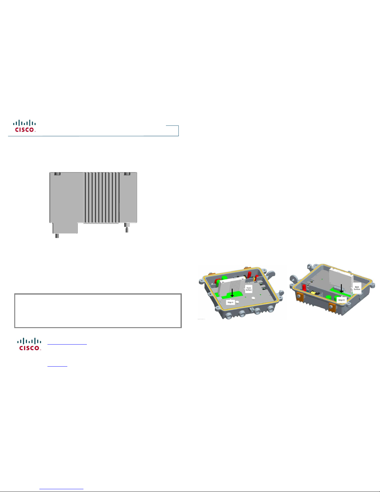
Follow the instructions below to install HPNA
module 1.
1. Power off the AP.
2. Place module 1 in a vertical position and
align its Front Surface with Edge A of the
white cover as shown on the right.
3. Insert the two module screws into the
screw holes and the single guide hole.
4. Gently adjust the module to align and
guide the module connector into the
main board connector.
5. Gently press module 1 and confirm that
the module connector is inserted
completely into the main board
connector.
6. Do not force the module connector into
the main board connector. Repeat steps
4-5 if you find it difficult to insert the
module connector into the main board
connector.
7. Tighten the two module screws with a
flat tip driver from 0.39 Nm to 0.98 Nm.
Module 2 Installation
Follow the instructions below to install HPNA
module 2.
1. Power off the AP.
2. Place module 2 in a vertical position and
align its Back Surface with Edge B of the
white cover as shown below.
3. Insert the two module screws into the
screw holes.
4. Gently adjust the module to align and
guide the module connector into the
main board connector.
5. Gently press module 2 and confirm that
the module connector is inserted
completely into the main board
connector.
6. Do not force the module connector into
the main board connector. Repeat steps
4-5 if you find it difficult to insert the
module connector into the main board
connector.
7. Tighten the two module screws with a
flat tip driver from 0.39 Nm to 0.98 Nm.
Module 1 Installation
Module 2 Installation
Quick Reference Guide
Page 2
用于 DigiStar 以太网同轴网络局端设备 (AP)的
HPNA 模块
简介
此快速安装指南供负责在 DigiStar 以太网同轴网络局端设备 (AP) 中安装 HPNA
模块的人员参考。如需获得更多关于安全、安装和操作的信息,可参考 DigiStar 以
太网同轴网络 (EoC) 局端设备 (AP) E230 安装与操作手册,部件号 4040979。
注意
卸下或安装 HPNA 模块之前请关闭 AP 的电源。热插拔 HPNA 模块可能会损坏 AP 主板
和 HPNA 模块。
请勿强行将 HPNA 模块连接器插入主板连接器。它可能会损坏 HPNA 模块上的连接器以
及主板上的连接器。
Cisco 和 Cisco 徽标是 Cisco 和/或其子公司在美国和其他国家/地区的注册商标或商标。以下网址详细记
录了 Cisco 和/或其子公司的所有注册商标:www.cisco.com/go/trademarks
本文档提及的所有其他商标均是其各自拥有者的商标。
产品和服务情况如有更改,恕不另行通知。
© 2011 Cisco 和/或其子公司。保留所有权利。
Cisco Systems, Inc.
86 400 8108886 接通后拨 4 号键 部件号 4042738 Rev A Number 7019941 Rev A
www.cisco.com 2011 年 10 月 February 2010
HPNA 模块安装
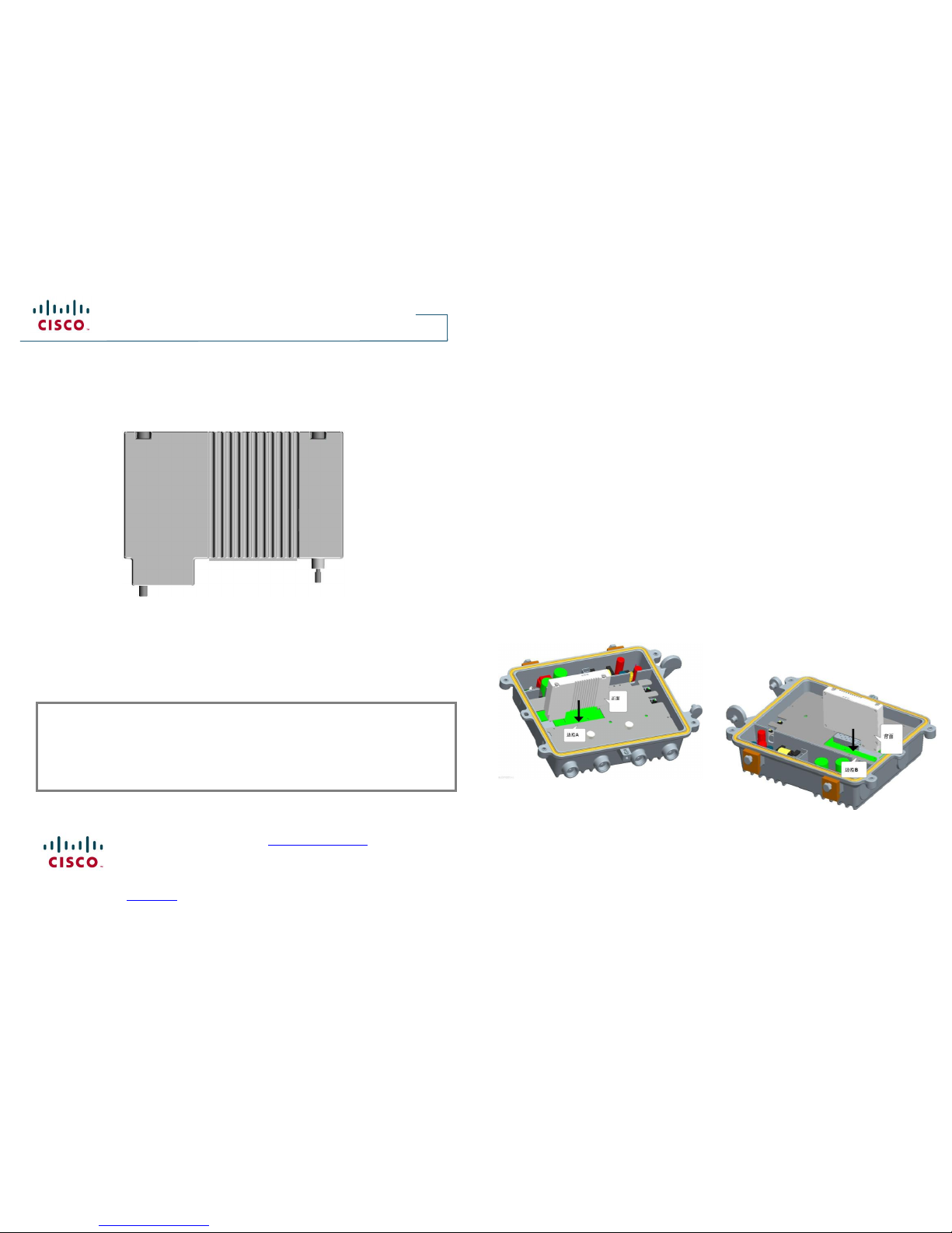
模块 1 安装
请按照以下步骤安装 HPNA 模块 1。
1. 关闭 AP的电源。
2. 将模块 1 垂直放置并将其正面与白色
盖板的边沿 A 对齐,如右所示。
3. 将 2 个模块螺丝分别与其螺孔及导孔
对齐。
4. 轻轻地调整模块,以对齐并引导模块
连接器进入主板连接器。
5. 轻轻地按压模块 1,并确认模块连接
器已全部插入到主板连接器。
6. 请勿强行将模块连接器插入主板连接
器。如果您发现难以将模块连接器插
入主板连接器,请重复第 4-5 步。
7. 使用一字螺丝刀以 0.39 Nm 至 0.98
Nm 的扭力拧紧 2 个模块螺丝。
模块 2 安装
请按照以下步骤安装 HPNA 模块 2。
1. 关闭 AP的电源。
2. 将模块 2 垂直放置并将其背面与白
色盖板的边沿 B 对齐,如下所示。
3. 将 2 个模块螺丝分别与其螺孔对
齐。
4. 轻轻地调整模块,以对齐并引导模
块连接器进入主板连接器。
5. 轻轻地按压模块 2,并确认模块连
接器已全部插入到主板连接器。
6. 请勿强行将模块连接器插入主板连
接器。如果您发现难以将模块连接
器插入主板连接器,请重复第 4-5
步。
7. 使用一字螺丝刀以 0.39 Nm 至
0.98 Nm 的扭力拧紧 2 个模块螺
丝。
Quick Reference Guide
模块 1 安装
模块 2 安装
快速安装手册
 Loading...