

Page 1

GoQAM Modulator RF Output
and IF Output Hardware
Installation and Operati on Guide
Page 2

Page 3

Please Read
Important
Please read this entire guide. If this guide provides installation or operation
instructions, give particular attention to all safety statements included in this guide.
Page 4

Notices
T rademark Acknowledgment s
Cisco and the Cisco logo are trademarks or registered trademarks of Cisco and/or its
affiliates in the U.S. and other countries. A listing of Cisco's trademarks can be found
at www.cisco.com/go/trademarks.
Third party trademarks mentioned are the property of their respective owners.
The use of the word partner does not imply a partnership relationship between
Cisco and any other company. (1009R)
Publication Discl aimer
Cisco Systems, Inc. assumes no responsibility for errors or omissions that may
appear in this publication. We reserve the right to change this publication at any
time without notice. This document is not to be construed as conferring by
implication, estoppel, or otherwise any license or right under any copyright or
patent, whether or not the use of any information in this document employs an
invention claimed in any existing or later issued patent.
Copyright
© 2007, 2012 Cisco and/or its affiliates. All rights reserved. Printed in the United States of
America.
Information in this publication is subject to change without notice. No part of this
publication may be reproduced or transmitted in any form, by photocopy,
microfilm, xerography, or any other means, or incorporated into any information
retrieval system, electronic or mechanical, for any purpose, without the express
permission of Cisco Systems, Inc.
Page 5

4004834 Rev D iii
Contents
Safety Precautions vii
FCC Compliance xi
About This Guide xiii
Chapter 1 Introducing the GoQAM 1
System Overview ..................................................................................................................... 2
GoQAM Input Pairs................................................................................................................. 6
Input/Output Process ............................................................................................................. 7
Front Panel Overview ........................................................................................................... 10
Back Panel Overview ............................................................................................................. 12
Chapter 2 Installing the GoQAM 15
Installation Process Summary .............................................................................................. 16
Unpack and Inspect the GoQAM ........................................................................................ 18
Record the MAC Address ..................................................................................................... 19
Stacking Guidelines ............................................................................................................... 20
Install the Modulator Into a Rack ........................................................................................ 24
Connect Power Sources ......................................................................................................... 27
Connect the DVB ASI Input Ports ....................................................................................... 29
Connect the 10/100BaseT Ethernet Port ............................................................................. 31
Connect the RF OUT or IF OUT Ports ................................................................................ 33
Chapter 3 Provision the RF GoQAM 37
Understand the RF GoQAM GUIs ...................................................................................... 38
Provision GoQAMs on the DNCS ....................................................................................... 46
Chapter 4 Provision the IF GoQAM 53
Understand the IF GoQAM GUIs ........................................................................................ 54
Understand the Set Up IF GoQAM GUI ............................................................................. 55
Understand the Set Up UpConverter GUI ......................................................................... 63
Provision an IF GoQAM on the DNCS ............................................................................... 71
Page 6

Contents
iv 4004834 Rev D
Chapter 5 Operating the RF Modulator 77
Understand the Boot Process ............................................................................................... 78
Change the Boot Mode .......................................................................................................... 81
Read the Default Status Screen ............................................................................................ 83
Use the Front Panel Keys to Change Configuration Settings .......................................... 84
Adjust the Frequencies of a Selected Carrier ..................................................................... 86
Adjust the RF Output Level of a Selected Carrier ............................................................. 87
Mute the RF Output of a Selected Carrier .......................................................................... 88
Change the Carrier Mode of a Selected Carrier ................................................................. 89
Monitor Setup Options .......................................................................................................... 90
Change an RF Carrier Frequency ........................................................................................ 98
Resetting the GoQAM ........................................................................................................... 99
Chapter 6 Operating the IF GoQAM 101
Understand the Boot Process ............................................................................................. 102
Change the Boot Mode ........................................................................................................ 105
Read the Default Status Screen .......................................................................................... 107
Use the Front Panel Keys to Change Configuration Settings ........................................ 108
Adjust the IF Output Level of a Selected Carrier ............................................................ 110
Mute the IF Output of a Selected Carrier ......................................................................... 111
Change the Carrier Mode of a Selected Carrier ............................................................... 112
Monitor Setup Options ........................................................................................................ 113
Select an IF Channel or Carrier .......................................................................................... 121
Chapter 7 Inspect the Modulator 123
Quarterly Inspection ............................................................................................................ 124
Replace the Fuse ................................................................................................................... 125
Diagnose the Fan .................................................................................................................. 127
Replace the Fan .................................................................................................................... 128
Chapter 8 Troubleshooting the GoQAM 131
Alarm Conditions ................................................................................................................ 132
Troubleshooting Alarm Messages ..................................................................................... 134
Troubleshooting Boot Screen Error Messages ................................................................. 143
Chapter 9 Customer Informati on 147
Page 7

Contents
4004834 Rev D v
Appendix A Technical Specif ications 149
Installation and Operation Requirements ........................................................................ 150
IF Specifications.................................................................................................................... 152
RF Specifications .................................................................................................................. 153
ASI Input Specifications ...................................................................................................... 154
Modulation Specifications .................................................................................................. 155
Digital I/O Performance Specifications ............................................................................ 156
Connector Type .................................................................................................................... 157
Factory Default Settings ...................................................................................................... 158
Standard Output Frequencies ............................................................................................ 159
Index 161
Page 8

Page 9
Safety Precautions
4004834 Rev D vii
Safety Precautions
Read, Retain, and F ollow Thes e Instructi ons
Carefully read all safety and operating instructions before operating this product. Follow all
operating instructions that accompany this product. Retain the instructions for future use.
Give particular attention to all safety precautions.
Warni ng and Cautio n Icons
WARNING:
Avoid personal injury and product damage! Do not proceed beyond any icon
until you fully understand the indicated conditions.
The following icons alert you to important information about the safe operation of this
product:
You will find this icon in the literature that accompanies this product. This icon
indicates important operating or maintenance instructions.
You may find this icon affixed to this product and in this document to alert you of
electrical safety hazards. On this product, this icon indicates a live terminal; the
arrowhead points to the terminal device.
You may find this icon affixed to this product. This icon indicates a protective earth
terminal.
You may find this icon affixed to this product. This icon indicates excessive or
dangerous heat.
You may find this symbol affixed to this product and in this document. This symbol
indicates an infrared laser that transmits intensity-modulated light and emits
invisible laser radiation and an LED that transmits intensity-modulated light.
Heed All Warnings
Adhere to all warnings on the product and in the operating instructions.
Avoid El ectric Shoc k
Follow the instructions in this warning.
WARNING:
To reduce risk of electric shock, perform only the instructions that are
included in the operating instructions. Refer all servicing to qualified service
personnel.
Page 10

Safety Precautions
viii 4004834 Rev D
Servicing
WARNING:
Avoid electric shock! Opening or removing the cover may expose you to
dangerous voltages.
Do not open the cover of this product and attempt service unless instructed to do so in the
operating instructions. Refer all servicing to qualified personnel only.
Cleaning, W ater, Moisture, Open Flam e
To protect this product against damage from moisture and open flames, do the following:
Before cleaning, unplug this product from the AC outlet. Do not use liquid or aerosol
cleaners. Use a dry cloth for cleaning.
Do not expose this product to moisture.
Do not place this product on a wet surface or spill liquids on or near this product.
Do not place or use candles or other open flames near or on this product.
Ventilation
To protect this product against damage from overheating, do the following:
This product has openings for ventilation to protect it from overheating. To ensure
product reliability, do not block or cover these openings.
Do not open this product unless otherwise instructed to do so.
Do not push objects through openings in the product or enclosure.
Placement
To protect this product against damage from breakage, do the following:
Place this product close enough to a mains AC outlet to accommodate the length of the
product power cord.
Route all power supply cords so that people cannot walk on, or place objects on, or lean
objects against them. This can pinch or damage the cords. Pay particular attention to
cords at plugs, outlets, and the points where the cords exit the product.
Make sure the mounting surface or rack is stable and can support the size and weight of
this product.
WARNING:
Avoid personal injury and damage to this product! An unstable surface may
cause this product to fall.
Page 11
Safety Precautions
4004834 Rev D ix
When moving a cart that contains this product, check for any of the following possible
hazards:
Move the cart slowly and carefully. If the cart does not move easily, this condition may
indicate obstructions or cables that you may need to disconnect before moving this cart
to another location.
Avoid quick stops and starts when moving the cart.
Check for uneven floor surfaces such as cracks or cables and cords.
WARNING:
Avoid personal injury and damage to this product! Move any appliance and
cart combination with care. Quick stops, excessive force, and uneven
surfaces may cause the appliance and cart to overturn.
Fuse
When replacing a fuse, heed the following warnings.
WARNING:
Avoid electric shock! Always disconnect all power cables before you change a
fuse.
WARNING:
Avoid product damage! Always use a fuse that has the correct type and rating.
The correct type and rating are indicated on this product.
Grounding This Pro duct (U.S .A. and Cana da Only)
Safety Plugs
If this product is equipped with either a three-prong (grounding pin) safety plug or a twoprong (polarized) safety plug, do not defeat the safety purpose of the polarized or
grounding-type plug. Follow these safety guidelines to properly ground this product:
For a 3-prong plug (consists of two blades and a third grounding prong), insert the plug
into a grounded mains, 3-prong outlet.
Note: This plug fits only one way. The grounding prong is provided for your safety. If
you are unable to insert this plug fully into the outlet, contact your electrician to replace
your obsolete outlet.
For a 2-prong plug (consists of one wide blade and one narrow blade), insert the plug
into a polarized mains, 2-prong outlet in which one socket is wider than the other.
Note: If you are unable to insert this plug fully into the outlet, try reversing the plug. The
wide blade is provided for your safety. If the plug still fails to fit, contact an electrician to
replace your obsolete outlet.
Page 12

Safety Precautions
x 4004834 Rev D
Grounding Terminal
If this product is equipped with an external grounding terminal, attach one end of an 18gauge wire (or larger) to the grounding terminal; then, attach the other end of the wire to an
earth ground, such as an equipment rack that is grounded.
20050727 Headend/Rack
Page 13

FCC Compliance
4004834 Rev D xi
FCC Compliance
Where this equipment is subject to U.S.A. FCC and/or Industry Canada rules, the following
statements apply.
United States FCC C ompliance
This device has been tested and found to comply with the limits for a Class A digital device,
pursuant to part 15 of the FCC Rules. These limits are designed to provide reasonable
protection against such interference when this equipment is operated in a commercial
environment.
This equipment generates, uses, and can radiate radio frequency energy, and if not installed
and used in accordance with the instruction manual may cause harmful interference to radio
communications. Operation of this equipment in a residential area is likely to cause harmful
interference, in which case users will be required to correct the interference at their own
expense.
Canada EMI Regulat ion
This Class A digital apparatus complies with Canadian ICES-003.
Cet appareil numérique de la class A est conforme à la norme NMB-003 du Canada.
20061110 FCC HE
Page 14

Page 15

About This Guide
4004834 Rev D xiii
About This Guide
Introduction
This guide describes both the intermediate frequency (IF) Gigabit Overlay
Quadrature Amplitude Modulation (GoQAM) modulator and the radio frequency
(RF) GoQAM.
Note: In this guide, the GoQAM modulator is referred to as the GoQAM.
The RF GoQAM is a software-modified Model D9479-1 Gigabit QAM (GQAM)
Modulator. The Model D9479-3 IF GoQAM is similar to the RF GoQAM, but has IF
outputs in lieu of RF outputs, as well as a different back panel. Both are integral
components of Cisco Overlay solution. The Overlay solution uses Digital Broadband
Delivery System (DBDS) technology to create a network in which different
conditional access (CA) systems can coexist in a coherent manner. Overlay
technology allows a PowerKEY
®
DBDS network to be “laid over” an existing cable
network that uses a different CA system.
Important: The GoQAM requires System Release (SR) 2.5/SR 3.5 (or later) with the
Overlay feature enabled.
Purpose
This guide provides detailed specifications and component descriptions for the
GoQAM and how the GoQAM functions in Cisco’s Overlay solution. This guide also
includes all of the procedures that enable you to install, provision, and operate the
GoQAM within your cable network. Call center personnel can use this guide to
assist them with common troubleshooting procedures.
Scope
This guide includes the following topics:
Descriptions of GoQAM functions
Descriptions of GoQAM components
Installation procedures
Operation procedures
Troubleshooting guidelines
Customer information
IF and RF GoQAM technical specifications
Page 16

About This Guide
xiv 4004834 Rev D
Audience
This guide is written for cable network system administrators and engineers,
operators of the Overlay DNCS, call center personnel, and system operators who are
responsible for installing, operating, maintaining, and troubleshooting the GoQAM.
Document V ersi on
This is the fourth release of this document. In addition to minor text and graphic
changes, the following table provides the technical changes to this document.
Description See Topic
Removed references to locking the front panel Throughout document
Updated compliance information Throughout document
Page 17

4004834 Rev D 1
Introduction
This chapter describes how the GoQAM functions within the Overlay
environment, explains how the GoQAM processes and outputs data, and
provides illustrations and descriptions of the front and back panel
components for both the IF and the RF versions of the GoQAM.
Important! You must be operating SR 2.5/SR 3.5 (or later) to install and
provision (configure) a GoQAM on your system.
1 Chapter 1
Introducing the GoQAM
In This Chapter
System Overview .................................................................................... 2
GoQAM Input Pairs ............................................................................... 6
Input/Output Process ............................................................................ 7
Front Panel Overview .......................................................................... 10
Back Panel Overview............................................................................ 12
Page 18
Chapter 1 Introducing the GoQAM
2 4004834 Rev D
System Overview
Diagram of Cisco’s Overlay Solution
The GoQAM is an integral component of the Overlay solution. The Overlay solution
uses Digital Broadband Delivery System (DBDS) technology to create a network in
which different conditional access (CA) systems can coexist in a coherent manner.
Overlay technology assumes that a PowerKEY DBDS network will be “laid over” an
existing but different cable network.
Important! The GoQAM is supported in SR 2.5/SR 3.5 (or later).
Depending on the system architecture, the GoQAM can be used in either headends
or hubs. The following illustrations are examples of typical Overlay environment
setups.
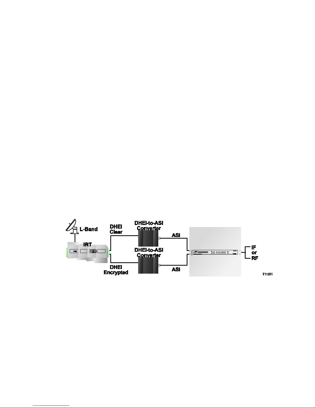
Overlay Environment Without a Multiplexer With an IRT
In an Overlay environment without a multiplexer (MUX), the Integrated Receiver
Transcoder (IRT) does the encryption for the non-Cisco set-tops.
The following graphic illustrates how Overlay technology interfaces to a non-Cisco
headend that uses a simple IRT. The IRT performs a number of functions including
Mediacipher encryption. With an IRT, clear and encrypted signals are available
through DHEI connectors on the IRT back panel.
Page 19
System Overview
4004834 Rev D 3
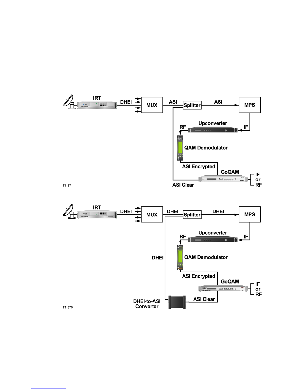
Overlay Environment With a MUX
In an Overlay environment with a MUX, the Modular Processing System (MPS) does
the encryption for the non-Cisco set-tops. The following graphics illustrate how
Overlay technology interfaces to a non-Cisco headend that uses a multiplexer
followed by an MPS. The MPS performs Mediacipher Encryption and may perform
QAM modulation, depending upon the specific device.
Example 1:
Example 2:
Note: The MPS is being replaced by the SmartStream Encryptor Modulator (SEM).
As with the MPS, a number of different options are available for interfacing Overlay
technology with the SEM. Specific details can be obtained by contacting Cisco
Services.
Page 20

Chapter 1 Introducing the GoQAM
4 4004834 Rev D
Features
The GoQAM provides many new digital broadcast features and innovations for your
system. The following table describes these features and innovations.
Feature Function
DVB ASI Input pairs
Supports a maximum ASI data rate of 216 Mbps (MPEG
packet rate) at all four inputs
Accepts two pairs of inputs. Each pair consists of an
incumbent-encrypted stream and its corresponding clear
stream. The GoQAM extracts critical packets—those without
which video cannot be reconstructed—and encrypts them
using Cisco PowerKEY encryption technologies. The GoQAM
also extracts the corresponding critical packets from the
incumbent-encrypted stream. Later, the PowerKEY packets
and the incumbent-encrypted critical packets are multiplexed
with the portion of clear stream that has not been encrypted.
10/100BaseT Ethernet
Interface
Provides a control and management interface to the DNCS
Multiplexing
Functionality
Provides program and packet identifier (PID) remapping and
filtering
MPEG Stream
Management
Provides program clock reference (PCR) timestamp correction
Provides program specific information (PSI) reconstruction
Provides transport stream monitoring
Allows adaptive insertion rate control
Stream Encryption,
Conditional Access,
and Management
PowerKEY Native stream encryption mode
Allows PowerKEY Book One ECM Handling
Provides MPEG packet insertion and entitlement control
messages (ECMs)
Supports broadcast clear-to-air and interactive encrypted
PowerKEY modes
IF Version:
64/256 QAM IF
Output (2)
Provides a separate physical connector for each QAM output
(up to 2 )
Provides a 44 MHz fixed output
Supports International Telecommunications Union (ITU) J.83
Annex-A, and Annex-B, and Annex-C standards
Page 21

System Overview
4004834 Rev D 5
Feature Function
RF Version:
64/256 QAM RF
Output (2)
Provides a separate physical connector for each QAM output
(up to 2)
Allows independent level control for each QAM signal
Allows an adjustable output center frequency range of
91 MHz to 869 MHz
Provides a switched filter bank for superior broadband
combined noise performance
Supports International Telecommunications Union (ITU) J.83
Annex-A, and Annex-B, and Annex-C standards
User Interface
Features
Allows local setting of RF power levels and display of diagnostic
and debug information through the front panel and user interface
Page 22
Chapter 1 Introducing the GoQAM
6 4004834 Rev D
GoQAM Input Pairs
The GoQAM associates the DVB ASI inputs as pairs of clear and encrypted inputs
for Overlay purposes. This means that each DVB ASI input constitutes a dedicated
pair of clear and encrypted streams. Each pair carries a clear digital broadcast stream
on one input and its encrypted form on the other input. For example, ASI IN 1 and
ASI IN 2 carry the clear and encrypted forms of the same digital transport stream,
respectively.
GoQAM Input Pairs Diagram
RF GoQAM Example
The following illustration depicts the fixed input and output combinations for an
RF GoQAM.
Note: For the RF GoQAM, input pair 1 can only be mapped to RF OUT 1, and input
pair 2 can only be mapped to RF OUT 3.
IF GoQAM Example
The following illustration depicts the fixed input and output combinations for an
IF GoQAM.
Note: For the IF GoQAM, input pair 1 can only be mapped to IF OUT 1, and input
pair 2 can only be mapped to IF OUT 2.
Page 23

Input/Output Process
4004834 Rev D 7
Input/Output Process
This section describes how the GoQAMs modulate, encrypt, and transmit the signals
they receive from external sources.
Input/Output Dia gram (RF Version)
The following diagram illustrates the stages of the input/output (I/O) process for
the RF GoQAM.
Note: The stage numbers correspond with the following table.
Input/Output Sta ge/Descript ion Table
The following table describes the stages of the I/O process of the RF GoQAM. The
numbers correspond to the above I/O diagram.
Stage Description
1 A pair of transport streams (a clear version and a third-party encrypted
version of the same stream) are input to the modulator.
2 The digital I/O board timestamps the MPEG packets in each stream, then
filters and routes them according to their PID values.
3 The digital I/O board selects the packets to pass from both the clear and
third-party encrypted streams.
4 PowerKEY encryption is added to selected clear packets and PID values are
remapped.
5 The clear and encrypted streams are synchronized.
6 An overlay output stream is created by muxing (multiplexing) the clear, S-A
encrypted, and third-party encrypted packets.
7 The output stream is modulated at 64 QAM or 256 QAM.
Page 24
Chapter 1 Introducing the GoQAM
8 4004834 Rev D
Stage Description
8 The I/O board directs the transport stream to one of the two RF Agile output
converters and sends the signal through the RF network to the DHCTs.
This section provides the installation process and lists the detailed procedures in this
guide that correspond with each process step.
Important: To ensure proper installation, read this entire guide before starting
installation and then follow these processes in the order shown.
Input/Output Dia gram (I F V ersion)
The following diagram illustrates the stages of the input/output (I/O) process for
the IF GoQAM.
Note: The stage numbers correspond with the following table.
Input/Output Sta ge/Descript ion Table
The following table describes the stages of the I/O process of the IF GoQAM. The
numbers correspond to the above I/O diagram.
Stage Description
1 A pair of transport streams (a clear version and a third-party encrypted
version of the same stream) are input to the GoQAM.
2 The digital I/O board timestamps the MPEG packets in each stream, then
filters and routes them according to their PID values.
3 The digital I/O board selects the packets to pass from both the clear and
third-party encrypted streams.
4 PowerKEY encryption is added to selected clear packets and PID values
are remapped.
Page 25

Input/Output Process
4004834 Rev D 9
Stage Description
5 The clear and encrypted streams are synchronized.
6 An overlay output stream is created by muxing (multiplexing) the clear,
S-A encrypted, and third-party encrypted packets.
7 The output stream is modulated at 64 QAM or 256 QAM and sent out one
of the two IF ports.
Page 26
Chapter 1 Introducing the GoQAM
10 4004834 Rev D
Front Panel Overview
Front Panel Diagr am
This illustration shows the front panel components of each type of GoQAM.
The following table describes the front panel components.
Item Component Description
1 MAJOR ALARM
indicator
This LED is red and lights for a major alarm condition.
Major alarms occur for hardware or software conditions that
indicate a serious disruption of service or the
malfunctioning or failure of important circuits. The LED
goes off when all major alarms have cleared.
2 MINOR ALARM
indicator
This LED is yellow and lights for a minor alarm condition.
Minor alarms indicate a less critical error condition. The
GoQAM may continue to operate with some loss of
functionality. The LED goes off when all minor alarms have
cleared.
3 CW indicator This LED is yellow and lights when any one of the RF
carriers is set to continuous wave (CW) mode.
4 LCD alphanumeric
display screen
This screen displays status and operating screens controlled
by the front panel keys.
5
The Down Arrow key decrements a displayed value or
navigates through a set of displayed values. This key is only
active when the display has a flashing value, which
indicates that the value can be changed. This key is
primarily used for decreasing a displayed value such as
frequency or level.
Page 27

Front Panel Overview
4004834 Rev D 11
Item Component Description
6
The Up Arrow key increments a displayed value or
navigates through a set of values. This key is only active
when the display has a flashing value, which indicates that
the value can be changed. This key is primarily used for
incrementing a displayed value such as frequency or level.
7
FREQ
RF Version: The Frequency key selects the frequency
display screen on which you can adjust the RF output
frequency for each of the RF carriers.
IF Version: The frequency is fixed at 44.00 MHz.
8
LEVEL
RF Version: The Level key selects the RF Output Level
screen on which you can adjust the RF output power
level and mute the RF output (42 dBmV to 56 dBmV).
IF Version: The Level key selects the IF Output Level
screen on which you can adjust the IF output power
level and mute the IF output (27 dBmV to 37 dBmV).
9
CW
The Continuous Wave (CW) key selects the Continuous
Wave Screen on which you can set the GoQAM modulator
to output either a modulated carrier or a continuous carrier
for each of the RF carriers.
CW mode is used for testing and not for normal operation.
10
OPTIONS
The Options key scrolls through status information and
setup options.
11
ENTER
The Enter key saves configuration changes to nonvolatile
memory.
12
RF SEL
RF Version: The RF Port Selection (RF SEL) key selects
one of the RF outputs.
IF Version: Selects one of the IF outputs.
Page 28
Chapter 1 Introducing the GoQAM
12 4004834 Rev D
Back Panel Overview
Back Panel Diagram
This illustration shows the back panel components for each type of GoQAM.
Back Panel Diagram
Back Panel Compon ents
The following table describes the back panel components.
Back Panel Compon ents
Important: The cooling fans for the GoQAM are mounted on the side panel.
Item Component Description
1 Power Switch On/off rocker-type power switch
2 Fuse Holder 4.0 A SLO BLO 250 V fuse (Cisco part number 188106)
3 AC Power Inlet IEC 320-conductor grounded outlet
4 RF OUT and
IF OUT Ports
F-connectors for RF or IF output, 75 Ω
Note: The RF GoQAM uses only RF OUT ports 1 and 3.
5 Gigabit Ethernet Port
LEDs
Not used (disabled) in the Overlay solution
Page 29
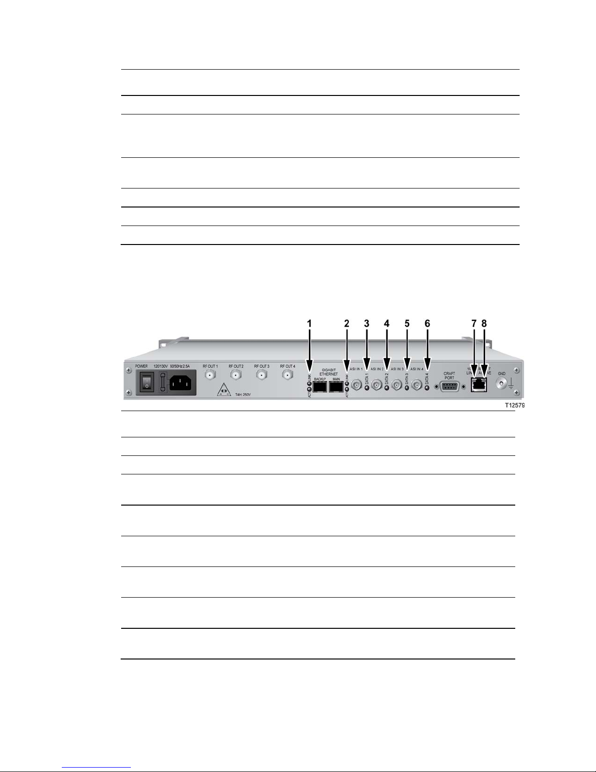
Back Panel Overview
4004834 Rev D 13
Item Component Description
6 Gigabit Ethernet port Not used (disabled) in the Overlay solution
7 DVB ASI INPUTS 1-4
Female BNC, 75 Ω connector. Allows for the input of
MPEG-2 transport stream data at a maximum rate of 216
Mbps
8 DVB ASI LEDs Data LEDs 1 through 4 light when the DVB ASI Input
ports are receiving valid MPEG-2 transport stream packets
9 CRAFT PORT For Cisco diagnostic use only
10 10/100BaseT port Ethernet port shares data with DNCS Ethernet hub
11 GND Ground screw for grounding the GoQAM
Back Panel Indicat or Lights
The following illustration and table show the back panel indicator lights.
Item Indicator Light Description
1 ACTIVE (green) Not used (disabled) in the Overlay solution
2 LINK (green) Not used (disabled) in the Overlay solution
3 DATA 1 (green) Lights when the DVB ASI Input 1 port is receiving
valid MPEG-2 transport stream (TS) packets
4 DATA 2 (green) Lights when the DVB ASI Input 2 port is receiving
valid MPEG-2 TS packets
5 DATA 3 (green) Lights when the DVB ASI Input 3 port is receiving
valid MPEG-2 TS packets
6 DATA 4 (green) Lights when the DVB ASI Input 4 port is receiving
valid MPEG-2 TS packets
7 LINK (yellow) Lights when a valid 10/100BaseT Ethernet link
connection exists
8 ACTIVE (green)
Lights when data traffic is on the 10/100BaseT Ethernet
link
Page 30

Page 31

4004834 Rev D 15
Introduction
This chapter describes how to install the GoQAM into a rack and where to
connect the GoQAM to the other components within the Overlay
environment. The connections used for the GoQAM vary according to its
use in your system.
Note: Refer to Technical Specifications (on page 149) for additional
technical specifications and requirements to help you install and configure
the GoQAM in your system.
2 Chapter 2
Installing the GoQAM
In This Chapter
Installation Process Summary ............................................................. 16
Unpack and Inspect the GoQAM ....................................................... 18
Record the MAC Address .................................................................... 19
Stacking Guidelines .............................................................................. 20
Install the Modulator Into a Rack ....................................................... 24
Connect Power Sources ........................................................................ 27
Connect the DVB ASI Input Ports ...................................................... 29
Connect the 10/100BaseT Ethernet Port ............................................ 31
Connect the RF OUT or IF OUT Ports ............................................... 33
Page 32

Chapter 2 Installing the GoQAM
16 4004834 Rev D
Installation Process Summary
Before Y ou Begin
This process assumes that you have already installed the GoQAM software on the
DNCS. Refer to the release notes and installation instructions for your GoQAM
release for detailed instructions. Also be sure that you have access to the Digital
Network Control System Online Help for your system release before installing the
GoQAM.
GoQAM Installation Pr ocesses
The following process summary provides the recommendations for a GoQAM
installation.
Stage Process See Procedure
1 Review system requirements and
technical specifications.
N/A
2 Consult your Bandwidth Management
Plan and the GoQAM input and
output specifications to allocate your
bandwidth resources properly.
N/A
3 Unpack and inspect the GoQAM.
Unpack and Inspect the GoQAM
(on page 18)
4 Record the MAC address from the
label located on the underside of the
GoQAM unit.
Record the MAC Address (on page
19)
5 Install the GoQAM into a rack.
Stacking Guidelines (on page 20)
Install the Modulator Into a Rack
(on page 24)
6 Connect the GoQAM to an earth
ground and then the power source.
For the 120/230 V AC GoQAM,
connect the power cord.
For the 48V DC GoQAM, connect
the power wires to the DC power
inlet.
Connect Power Sources (on page
27)
7 Connect other network devices to the
GoQAM, except the RF out ports.
Connect the DVB ASI Input Ports
(on page 29)
Connect the 10/100BaseT Ethernet
Port (on page 31)
Page 33

Installation Process Summary
4004834 Rev D 17
Stage Process See Procedure
8 Define the MPEG sources and
provision the GoQAM using DNCS
Element Provisioning according to
your network wiring diagram.
Provision the RF GoQAM (on
page 37)
Provision the IF GoQAM (on page
53)
Digital Network Control System
Online Help
9 Power on the GoQAM N/A
10 Ensure that the GoQAM boots
correctly and check for alarms from the
front panel.
Understand the Boot Process (on
page 78)
Troubleshooting Alarm Messages
(on page 134)
Troubleshooting Boot Screen Error
Messages (on page 143)
11 Connect the RF or IF output ports.
Connect the RF OUT or IF OUT Ports
(on page 33)
12 Set the power output level in
accordance with your network wiring
diagram and spectrum analyzer
measurements.
Adjust the RF Output Level of a
Selected Carrier (on page 87)
Adjust the IF Output Level of a
Selected Carrier (on page 110)
13 If sessions have been defined for the
GoQAM path, verify the correct
session count by pressing the
OPTIONS button.
RF: Viewing the Session Count (on
page 91)
IF: Viewing the Session Count (on
page 114)
14 If encrypted, check the program count.
RF: Viewing the Program Count
(on page 91)
IF: Viewing the Program Count (on
page 114)
15 Verify video and audio from a local
DHCT.
See the post-upgrade procedures for
your current System Release contained
in the upgrade installation
instructions.
Page 34

Chapter 2 Installing the GoQAM
18 Error! No text of specified style in document.
Unpack and Inspect the GoQAM
Carrier’s Respo nsibili ty
Cisco thoroughly inspects and carefully packs all products before shipment. The
carrier is responsible for safe shipping and delivery.
If there are any missing parts or if there is damage to the product contact Cisco
Services.
Retain all boxes for future equipment shipping needs. The boxes are specifically
designed for shipping the GoQAM.
Unpacking and Inspe cting Proce dure
Complete the following steps to unpack and inspect the modulator.
1 Review the Safety Precautions.
2 Inspect the shipping carton for visible damage.
3 Open the shipping carton.
4 Remove all packing material.
5 Inspect the product for visible damage.
6 Inspect for loose items that may indicate concealed damage.
7 Inspect for missing parts using the packing slip as a guide.
8 Go to Record the MAC Address (on page 19).
Page 35

Record the MAC Address
Error! No text of specified style in document. 19
Record the MAC Address
This section contains instructions for recording the MAC address as part of the
installation process.
Recording the MAC Addr ess
1 Unpack and inspect the modulator.
2 Locate the label containing the MAC addresses on the underside of the chassis.
Important! The GbE MAC addresses are typically the MAC address of the
modulator plus 1 (one).
Examples:
GQAM MAC Address: 00:02:de:41:51:03
GbE MAC Address (Main): 00:02:de:41:51:04
GbE MAC Address (Backup): 00:02:de:41:51:05
3 Record the MAC addresses here:
- GQAM MAC Address: ______________________________________
- GbE MAC Address (Main): _______________________________________
- GbE MAC Address (Backup): _____________________________________
Important! You will need these MAC addresses for provisioning (configuring)
the DNCS.
4 Go to Stacking Guidelines (on page 20).
Page 36

Chapter 2 Installing the GoQAM
20 4004834 Rev D
Stacking Guidel ine s
The GoQAM is a high-density, high performance device for digital broadband data
delivery. One GoQAM performs the services of two QAM modulators. This spacesaving feature makes the GoQAM the device of choice for contemporary digital
broadband delivery systems.
Providing proper ventilation and cooling for the modulator is mandatory. You can
stack up to 32 GoQAM devices in a standard 40-rack unit (RU) equipment rack if
you read and carefully follow the guidelines provided in this section and later in this
chapter.
Each GoQAM contains three dual fan packs that provide forced air cooling. These
fan packs, located on the side of the unit, pull air across the internal circuitry to
remove heat.
Important! In order for the fans to operate correctly, you must install each GoQAM
using the rack mount brackets included with the unit. These brackets contain
notched cutout sections to allow for clearance so that air can enter and leave the unit
without restriction.
When you install the GoQAM in the rack using the rack mounts provided, you can
install them directly above and below each other with no requirements for vented
spacers. Using these rack mounts also provides support for the modulator. The
GoQAM is not intended to be suspended or “hung” in the rack by only mounting the
front bezel support.
Controlling Operat ing Temperature
CAUTION:
Cisco headend equipment is designed to operate in a maximum 122°F (50°C)
environment. Specifically, this means that the air temperature at the air inlet
of any GoQAM must never exceed 122°F (50°C).
Each GoQAM draws up to 151 W of input power and a total of 515 BTU/hr. For a
full rack with 32 units, the sum total is 4832 W per rack, or 16,480 BTU/hr. You
should make your HVAC considerations based on these calculations.
Controlling Exhaust Air
Exhaust air management is the key to cooling multiple modulators in a custom rack
configuration. Inlet air temperature should be as cool as possible and should never
exceed 122°F (50°C). Exhaust air should have little or no restrictions. Obstructions
such as cabling or other devices that block airflow to the side or top of the rack
should be avoided.
Page 37

Stacking Guidelines
4004834 Rev D 21
Considerations When Using Side by Side Equipment Racks
Often, side-by-side equipment racks will not include an internal wall between them.
You should take extreme care when installing modulators in these types of systems.
There is approximately an 18°F (10°C) rise from inlet air temperature to exhaust air
temperature on a GoQAM. This rise in temperature could have a cumulative effect
on temperature from one rack to the adjacent one. You must take extreme care not to
exceed the 122°F (50°C) maximum inlet air temperature requirement in these
situations.
Considerations When Using Racks with a Wall on One Side
Rack installations that have the outer wall or side of the rack in place on the exhaust
side of the GoQAM should note that without sufficient airflow through the rack, the
heated exhaust air may re-circulate back to the input side of the GoQAM. Depending
on the situation, this re-circulation air could eventually exceed the specified 122°F
(50°C) maximum.
Measuring the Inl et Air Temperature
If you are concerned about inlet air temperature, you should measure the
temperature of the inlet air in the actual rack as you plan to use it. You should have
all cabling in place and all adjacent units installed and running.
Important! Opening the door on the back panel of the rack can have an adverse effect
on the managed airflow. If access to the door on the back panel is not controlled, you
should take the inlet air temperature with the back panel door open since, in most
instances, opening the door will re-direct the airflow in an adverse manner.
Stacking Consider ations
You have two main options for stacking GoQAMs in a rack. The option you choose
depends on your system requirements. One option is to stack the GoQAMs in a rack
containing a top-mounted exhaust fan with vented panels on the front and back. The
second option is to place a top-vented rack over a floor plenum forced air vent. The
requirements for these two stacking options are described next in this section.
Option 1 – Using a Rack With a Top-Mounted Exhaust Fan
This stacking option uses a 40 RU configuration containing up to 32 GoQAMs. The
remaining 8 RUs are configured with 4 RUs at the bottom and 4 RUs at the top.
The 4 RU space at the bottom is covered with a vented panel on both the front and
the back. This panel allows air to freely enter the rack to cool the modulators.
Page 38

Chapter 2 Installing the GoQAM
22 4004834 Rev D
The 4 RU space at the top is covered with a closed panel. This option uses an exhaust
fan located on top of the rack to draw the heated air upward and out of the rack. The
4 RU space at the top allows the ventilation space needed for the exhaust fan to
operate efficiently. The exhaust fan should be chosen so that a minimum of 600 cubic
feet per minute (cfm) flows through the rack with 2000 cfm being the ideal amount.
Example:
Page 39

Stacking Guidelines
4004834 Rev D 23
Option 2 – Using a Rack With Floor Plenum Forced Air Cooling
This stacking option also uses a 40 RU configuration containing up to 32 GoQAMs.
In Option 2, however, the lower 4 RU space is covered with a solid panel instead of a
vented one. The upper 4 RU space is vented along with the entire top of the rack.
The floor plenum forced airflow must also be a minimum of 600 cfm with 2000 cfm
being the ideal amount.
Example:
Page 40

Chapter 2 Installing the GoQAM
24 4004834 Rev D
Install the Modulator Into a Rack
The front bezel of the GoQAM mounts to the front of the equipment rack. The
GoQAM fits into an EIA RS-310 rack mount.
Important! You must read the preceding section, Stacking Guidelines (on page 20),
before installing the modulators into the rack.
Installation Req uirements
This section lists the power, rack, and environmental conditions necessary for
installation.
Power Requirements Table
The following table describes the power specifications for the GoQAM.
Item Specification
Supply Voltage
90V to 130V AC @ 47 to 63 Hz (AC unit)
180V to 264V AC @ 47 to 63 Hz (AC unit)
–42V to –57V DC (DC unit)
Fuses
4.0 A SLO BLO 250V (AC unit)
6.3 A SLO BLO 250V (DC unit)
Line Frequency
47 Hz to 63 Hz (AC unit only)
Power Required
RF GoQAM: 155 VA (typical)
IF GoQAM: 85 VA (typical)
Power Dissipated
RF GoQAM: 151 Watts (typical)
IF GoQAM: 81 VA (typical)
In Rush Current
35 amps maximum, Vin = 130V AC (AC unit)
75 amps maximum, Vin = 264V AC (AC unit)
15 amps maximum, Vin = -57V DC (DC unit)
Page 41

Install the Modulator Into a Rack
4004834 Rev D 25
Rack Requirements Table
Item Specification
Rack Mount Type EIA RS-310
Height 1.75 in./44.45 mm
Width 19 in./482.6 mm
Depth 22.5 in./571.5 mm
Weight 13.5 lb./5.4 kg
Environmental Requirements Table
Item Specification
Operating Temperature 0° to 50°C (32° to 122°F)
CAUTION:
Avoid damage to this product! Your warranty
is void if you operate this product above the
maximum specified operating temperature.
Use caution when installing wiring and racks
to avoid obstruction of air flow. The
obstruction can occur at the side air vents of
the GoQAM or the vent fans at the GoQAM
side panel.
Important! You must use the supplied notched rack
mounts (Cisco part numbers 734845 and 734846) to
mount this modulator into the rack. These rack mounts
allow correct air circulation through the unit.
Storage Temperature Range -10° to 70°C (14° to 158°F)
Operating Humidity 5 to 95%, non-condensing
Vibration Susceptibility No data errors with a chassis vibration of 0.5 Gs. No
data errors with a vibration frequency of 10 Hz to 400
Hz
Electrostatic Shock Susceptibility No damage sustained from five discharges of 15 KV IEC
electrostatic discharge model (150pF + 150 Ω) to all
exposed connections
Page 42

Chapter 2 Installing the GoQAM
26 4004834 Rev D
Installing the Mod ulator i nto a Rack
CAUTION:
Do not tangle or strain interconnecting cables.
Use caution when installing wiring and racks to avoid obstruction of airflow
into the side air vents of the GoQAM or out of the vent fans on the side of the
GoQAM.
IMPORTANT: You must use the supplied notched rack mounts to provide
additional support and to allow correct air circulation through the unit.
1 Install the rack mounts.
Important: The supplied rack mounts (Cisco part numbers 734845 and 734846)
must be used. When you use the supplied rack mounts, you can install these
modulators above or below each other in the rack with no space required. These
rack mounts provide additional support along with the following features:
Attaches directly to the rack
Allows you to slide modulators partially out of the rack for service
Allows appropriate air circulation throughout the unit
2 Place the modulator in the rack.
3 Insert a mounting screw through each of the four-bezel mounting holes on the
front panel of the GoQAM and then into the rack.
4 Firmly tighten each mounting screw.
5 Go to Connect Power Sources (on page 27).
Page 43

Connect Power Sources
4004834 Rev D 27
Connect Power Sources
This section contains instructions for connecting the DC and AC power sources to
the modulator.
Connecting an Eart h Ground
Complete the following steps to connect an earth ground to either the DC or AC
versions of the GoQAM.
CAUTION:
The 48 V DC GoQAM must be connected to an earth ground.
1 Place a ground wire onto the ground lug (marked GND) on back of the GoQAM;
then, use your fingers to tighten the ground lug to secure the ground wire.
2 Connect the other end of the ground wire to the rack or earth ground.
Connecting a DC Po wer Source
Complete the following steps to connect a DC power source to the 48 V DC Dual SFP
GQAM.
1 Verify that the DC power source is set to the Off position.
2 Insert the wires from the DC power source into the terminal block connector. Use
a small flat-blade screwdriver to tighten the screws at the top of the terminal
block connector to secure the wires.
Page 44

Chapter 2 Installing the GoQAM
28 4004834 Rev D
3 Insert the terminal block connector into the terminal block on the back panel of
the 48 V DC GoQAM.
4 Keep the DC power source set to the Off position until you are ready to power
on the modulator.
5 Go to Connect the DVB ASI Input Ports (on page 29).
Connecting an AC Pow er Source
Complete the following steps to connect an AC power source to the 120/230 V AC
GoQAM.
1 Verify that the power switch on the back panel is placed in the Off position.
2 Connect the power cord to the AC power inlet on the back panel of the 120/230
V AC GoQAM.
3 Connect the other end of the power cord to an AC electrical outlet.
4 Keep the power switch in the Off position until you are ready to power on the
device.
5 Go to Connect the DVB ASI Input Ports (on page 29).
Page 45

Connect the DVB ASI Input Ports
4004834 Rev D 29
Connect the DVB ASI Input Ports
Description
The GoQAM uses ASI input pairs to receive data from ASI-compliant transmitting
devices such as Integrated Receiver Transcoders (IRTs) and MPEG multiplexers.
These ASI inputs conform to the DVB document A010. The DVB ASI Input ports are
BNC-type connectors and connect to 75 Ω coaxial cables. Each DVB ASI Input port
allows for the input of MPEG-2 transport stream (TS) data at a maximum rate of 216
Mbps.
Location of DVB ASI Input Ports
The following illustration shows an example of an IF GoQAM connected to DVB ASI
sources.
Page 46

Chapter 2 Installing the GoQAM
30 4004834 Rev D
Connecting the DVB ASI Ports
Refer to your network wiring diagram to cable the GoQAM in accordance with your
bandwidth allocation plan.
Follow these steps to connect each of the DVB ASI Input ports.
1 Locate the output (DHEI or DVB ASI) on the back of an output device.
Important: If you are connecting an IRT or other DHEI device, you must first
connect a DHEI cable to a DHEI-to-ASI converter before connecting to the
GoQAM.
2 To connect input pair 1, connect clear feed #1 to ASI input port 1 and encrypted
feed #1 to ASI input port 2.
Note: The maximum recommended length for the cable is 100 meters.
3 To connect input pair 2, connect clear feed #2 to ASI input port 3, and encrypted
feed #2 to ASI input port 4.
Note: The maximum recommended length for the cable is 100 meters.
4 Repeat steps 2 and 3 for all DVB ASI inputs according to your system’s
specifications and requirements.
5 Go to Connect the 10/100BaseT Ethernet Port (on page 31).
Page 47

Connect the 10/100BaseT Ethernet Port
4004834 Rev D 31
Connect the 10/100BaseT Ethernet Port
Description
The GoQAM shares data with the DNCS through an ATM switch, a router, an
Ethernet hub, and an Ethernet port. An Ethernet connection enables the DNCS to
perform software downloads, provision the GoQAM, set up broadcast sessions,
monitor alarms, and check system performance.
Note: Connect the 10/100BaseT Ethernet port on the GoQAM to an Ethernet hub as
part of an Ethernet connection. Do not connect it directly to a DNCS workstation or
another PC.
Location of 10/10 0BaseT Eth ernet Port
The following illustration shows an example of a 10/100BaseT Ethernet connection
for the IF GoQAM.
Page 48

Chapter 2 Installing the GoQAM
32 4004834 Rev D
Connecting the 10/ 100BaseT Et hernet Por t
Follow these steps to connect the GoQAM to the Ethernet network.
1 Connect the DNCS to the ATM switch using multi-mode fiber.
2 Connect the ATM switch to the router using single mode fiber.
3 Connect the router to the 10/100BaseT Ethernet hub using CAT-5 Ethernet
10/100BaseT wiring with RJ-45 connectors.
4 Connect the 10/100BaseT port on the GoQAM to the 10/100BaseT Ethernet hub
using CAT-5 Ethernet 10/100BaseT wiring with RJ-45 connectors.
Note: Use a screened or shielded cable to connect the GoQAM to the
10/100BaseT Ethernet hub.
5 Your next step is to provision the GoQAM on the DNCS. See Provision the RF
GoQAM (on page 37) or Provision the IF GoQAM (on page 53), for further
details about provisioning the GoQAM on the DNCS. Then, go to step 6.
6 After your have provisioned the GoQAM on the DNCS, power on the GoQAM
to ensure that the GoQAM boots correctly and check for alarms from the front
panel.
7 Go to Connect the RF OUT or IF OUT Ports (on page 33).
Page 49

Connect the RF OUT or IF OUT Ports
4004834 Rev D 33
Connect the RF OUT or IF OUT Por ts
The back panel of the GoQAM contains ports that are labeled either RF OUT or IF
OUT depending on the model of GoQAM you are using. The RF OUT or IF OUT
ports of the GoQAM should be connected to a system of combiners, through the
cable system, and eventually to subscribers’ DHCTs. Each RF OUT or IF OUT port
provides for the transport of MPEG-2 transport stream (TS) data. The RF OUT and IF
OUT ports use F-connectors and 75 Ω coaxial cable interfaces.
Note: The Overlay solution uses only two of the RF OUT ports (RF OUT 1 and RF
OUT 3) on the RF GoQAM modulator.
CAUTION:
Turning on the GoQAM with default RF output level may cause RF
interference with the services of other units connected to the network.
Therefore, set the RF output frequency and RF output level before you
connect any RF OUT ports to the network.
Important! We strongly recommend that you configure and adjust
frequencies from the Set Up GoQAM window on the DNCS. See
Provision GoQAMs on the DNCS (on page 46) or Provision an IF
GoQAM on the DNCS (on page 71) for detailed instructions.
Location of RF OUT Por ts
The following illustration shows an example of two of the four RF OUT ports
connected to the distribution plant.
Note: The RF GoQAM uses only the RF OUT 1 and RF OUT 3 ports.
Page 50

Chapter 2 Installing the GoQAM
34 4004834 Rev D
Location of IF OUT P orts
The following illustration shows an example of the two IF OUT ports on the IF
GoQAM connected to the upconverter.
Connecting the RF O ut or IF OUT Por ts
Follow these steps to connect the RF OUT or IF OUT ports.
CAUTION:
Establish the RF output level and the IF output level before you
connect the RF OUT or IF OUT ports to the distribution plant.
Important: We strongly recommend that you configure and adjust frequencies
from the Set Up GoQAM window on the DNCS. See Provision the RF
GoQAM (on page 37), or Provision the IF GoQAM (on page 53) for detailed
instructions.
1 Refer to your network wiring diagram to connect the GoQAM properly.
2 Locate the RF OUT or IF OUT ports on the back panel of the GoQAM.
3 Connect one end of a 75 Ω coaxial cable to each port to be used for the GoQAM.
4 Verify that you have established the correct output level for the RF OUT or the IF
OUT ports by completing the following steps:
a Connect the GoQAM to a spectrum analyzer to measure radio frequency
levels.
b Set the RF or IF output levels from the front panel of the GoQAM.
c Provision the GoQAM from the DNCS.
Notes:
For the RF GoQAM, see Adjust the RF Output Level of a Selected Carrier (on
page 87) and Provision GoQAMs on the DNCS (on page 46) for more
information.
For the IF GoQAM, see Adjust the IF Output Level of a Selected Carrier (on
page 110) and Provision an IF GoQAM on the DNCS (on page 71) for more
information.
Page 51

Connect the RF OUT or IF OUT Ports
4004834 Rev D 35
5 Choose one of the following options:
For the RF GoQAM, connect the other end of each 75 Ω coaxial cable to the
distribution plant.
For the IF GoQAM, connect the other end of each 75 Ω coaxial cable to an
upconverter.
Page 52

Page 53

4004834 Rev D 37
Introduction
This chapter provides examples and descriptions of the DNCS graphical
user interfaces (GUIs) used for provisioning (configuring) the RF
GoQAM in an Overlay environment. Provisioning the GoQAM prepares
the device so that the DNCS recognizes it and so that it operates
properly.
Important! Your system must be operating SR 2.4/SR 3.4 (or later) to
use a GoQAM on your system. You must also have the Overlay feature
enabled.
Note: See Technical Specifications (on page 149) for the technical
specifications of the RF GoQAM and consult your network wiring
diagram when you provision the GoQAM to ensure a proper allocation
of bandwidth.
For more information about the DNCS and operating the DNCS
software, refer to the Digital Network Control System Online Help for your
system release.
3 Chapter 3
Provision the RF GoQAM
In This Chapter
Understand the RF GoQAM GUIs ..................................................... 38
Provision GoQAMs on the DNCS ...................................................... 46
Page 54

Chapter 3 Provision the RF GoQAM
38 4004834 Rev D
Understand the RF GoQAM GUIs
This section provides examples and descriptions of the GUIs used for provisioning
the RF GoQAM as a DBDS network element in an Overlay environment.
Important! Actual GUIs may differ slightly from the GUIs presented in this guide.
Understanding the RF GoQAM GUIs
Use the DNCS RF GoQAM GUIs to provision the RF GoQAM on the DNCS. The
main GUI is the Set Up RF GoQAM window. The Set Up RF GoQAM window
contains the following fields:
Basic Parameters
Advanced Parameters
Connectivity
Note: This section includes examples and descriptions of all of the areas within these
fields.
Understanding Basi c Paramet ers
The Basic Parameters fields allow you to identify the GoQAM, assign it to a
headend, and specify the modulation type for each of the RF Out ports. If you want
to view the Basic Parameters fields while reading this section, follow these steps to
examine the Set Up RF GoQAM window.
1 From the DNCS Administrative Console, select one of the following tabs:
For SR 2.7/3.7/4.2 and later, click the Network Element Provisioning tab.
For SR 2.5/3.5/4.0 and earlier, click the Element Provisioning tab.
2 Click QAM. The QAM List window opens.
Page 55

Understand the RF GoQAM GUIs
4004834 Rev D 39
3 Select File > New > GOQAM > RF GOQAM. The Set Up RF GoQAM window
opens with the Basic Parameters tab to the forefront and displays the Basic
Parameters fields as shown in the following example.
Basic Parameters
The following table lists the Basic Parameters fields and their descriptions.
Field Description
Headend Name Displays the name of the headend with which the modulator
is associated
QAM Name Displays the name used for the modulator
IP Address Displays the IP address of the Ethernet interface through
which the DNCS manages and controls the modulator
Modulation Type Allows you to specify one of the following modulation types
for each of the carriers:
ITU J.83 Annex B (6 MHz)
ITU J.83 Annex C DAVIC/DVB
(6 MHz)
Note: The default value is ITU J.83 Annex B (6 MHz).
Page 56

Chapter 3 Provision the RF GoQAM
40 4004834 Rev D
Field Description
Administrative State Specifies whether the modulator is active within the system.
The values are:
Offline: Default
Online: Active
MAC Address Displays the MAC address of the GoQAM
Subnet Mask Displays the IP subnet mask assigned by the system
administrator
Default Gateway Displays the network default gateway assigned by the
system administrator
Ports
The following table lists the Ports field descriptions.
Field Description
Reserved TSID Range Identifies the available range of Transport Stream IDs (TSIDs)
Input Block 1 ASI 1 Clear
Transport Stream ID
Identifies the Transport Stream ID for input block 1 at ASI 1
Input Block 2 ASI 3 Clear
Transport Stream ID
Identifies the Transport Stream ID for input block 2 at ASI 3
Port to Hubs Allows you to specify which hub is associated to any selected
RF output port. The default is all hubs under the defined
headend
RF Out Parameters
The following table lists the RF OUT port (1 – 2) field descriptions.
Note: Overlay technology uses only two of the RF OUT ports on the RF GoQAM.
Field Description
Modulation Displays the modulation format of the individual carriers
The default is 64-QAM for ITU J.83 Annex B.
Transport Stream ID Displays the identifier of the transport stream ID for each RF
Out module
Page 57

Understand the RF GoQAM GUIs
4004834 Rev D 41
Field Description
Channel Center Frequency
(MHz)
Displays the frequency assigned to each carrier (range is 91
MHz to 869 MHz). Valid frequencies use the following format,
with XXX representing a number from 91 to 869:
XXX.000
XXX.25
XXX.75
Continuous Wave Mode Provides an unmodulated RF carrier
Note: Continuous wave mode may be selected for each carrier.
Mute RF Output Disables the RF output. May be selected for each carrier.
Disabled Prevents the DNCS from setting up any additional sessions on
this RF output if the DNCS is choosing QAM resources. Existing
sessions are not affected and continue to function as expected.
May be selected for each RF output.
Interleaver Depth Allows you to select the Interleave setting based on the type of
set-top you are using on your system. Interleaving is a
technique to overcome correlated channel noise. Interleaving
spreads out bursts of errors to remain within the errorcorrecting ability of a device.
Function Keys
The following function keys appear on the Set Up GoQAM window.
Key Function
Save Saves changes to settings and closes the Set Up GoQAM window
Apply Makes changes to settings without closing the Set Up GoQAM
window
Cancel Closes the Set Up GoQAM window without saving changes that
have not been previously applied to settings
Help Opens the DNCS Online Help
Page 58

Chapter 3 Provision the RF GoQAM
42 4004834 Rev D
Understanding Adv anced Parameters
The Advanced Parameters fields of the Set Up RF GOQAM window allow you to
select the configuration file. To view the Advanced Parameters fields while reading
this section, click the Advanced Parameters tab in the Set Up RF GOQAM window.
The following diagram shows an example of the Advanced Parameters fields of the
Set Up RF GOQAM window.
Advanced Parameters
The following table lists Advanced Parameters field descriptions.
Field Description
Configuration File Name Displays the name of the configuration file used by the RF
GoQAM to determine whether it is running the correct
version of application code
Select Opens the File Selection Dialog window so that you can
specify the configuration file for the selected RF GoQAM.
Understanding the File Select ion Dialog Screen
The File Selection Dialog screen allows you to specify the configuration file for the
RF GoQAM. To view the File Selection Dialog screen while reading this section, click
the Select button on the Advanced Parameters tab.
Understanding the BOOTP/TFTP Process
The BOOTP/TFTP process allows the GoQAM, after power on or reset, to request an
IP address and receive configuration parameters, application downloads, and
provisioning from the network BOOTP server. The DNCS, which is a BOOTP server,
uses a BOOTP reply to assign an IP address to the GoQAM if the unit is provisioned
in the DNCS database.
The configuration file selected in the File Selection Dialog window is included in the
BOOTP reply. The GoQAM uses the information in the configuration file to
determine whether it is running the correct version of application code. If the
GoQAM is not running the correct version of application code, it requests the correct
image file(s) from the DNCS.
Page 59

Understand the RF GoQAM GUIs
4004834 Rev D 43
The following diagram shows an example of the File Selection Dialog window.
Function Keys
The following function keys appear in the File Selection Dialog screen.
Key Function
OK Places the selected file name into the Configuration File Name field
and closes the File Selection Dialog window
Filter Enables the contents of the directory to display in the Directories
and Files fields
Cancel Closes the File Selection Dialog window without changing the
original settings
Page 60

Chapter 3 Provision the RF GoQAM
44 4004834 Rev D
Understanding Con nectivit y
The Connectivity fields of the Set Up RF GoQAM window allow you to specify the
input device connected to each of the Input ports on the GoQAM.
Note: When you first provision the RF GoQAM, the Connectivity fields are
accessible only after you click Apply or Save from the Set Up RF GOQAM window.
Thereafter, the Connectivity fields are accessible for viewing or modification.
To view the Connectivity fields while reading this section, click the Connectivity tab
in the Set Up RF GOQAM window.
The following diagram shows an example of the Connectivity fields of the Set Up RF
GOQAM window.
Page 61

Understand the RF GoQAM GUIs
4004834 Rev D 45
Connectivity
The following table lists the Connectivity field descriptions.
Field Description
QAM Name Identifies the name of the selected RF GoQAM and allows you
to specify the Input (ASI) Port (1 or 3)
Headend Name Identifies the headend in which the input device exists
Device Type Identifies the type of input device, such as an Automux or IRT
to which the RF GoQAM is connected
Device Name Identifies the name of the input device to which the RF GoQAM
is connected
Port Number Identifies the port number of the device that is connected to the
RF GoQAM. The server should be entered in the DNCS as a
generic MPEG source. Create as many ports as are available for
the server and connect to the RF GoQAM
Show TSIDs/IPs Displays the Transport Stream (TS) IDs and Internet Protocol
addresses (IPs)
Show (slot, port) Displays the slot and port of the card connected to the RF
GoQAM
Legend Displays a group of icons that represent network elements that
may be displayed in the graphical drawing area
Page 62

Chapter 3 Provision the RF GoQAM
46 4004834 Rev D
Provision GoQAMs on the DN CS
In order for the RF GoQAM to operate properly as a network element within the
DBDS, you must provision the RF GoQAM on the DNCS. This section provides
procedures for provisioning an RF GoQAM on the DNCS.
Before Y ou Begin
Before you begin to provision the GoQAM on the DNCS, you need the following
information:
IP address of the GoQAM
Physical (MAC) address of the GoQAM
Name you need to assign to the GoQAM
Headend to which you need to assign the GoQAM
RF frequencies for each output port
Modulation type this GoQAM will use
Transport Stream IDs for each port of the GoQAM
Interleaver Depth for this GoQAM
Provisioning an R F GoQAM on the DNC S
Follow these steps to provision a new RF GoQAM or to adjust the settings for an
existing RF GoQAM on the DNCS.
1 Verify that you have provisioned the RF GoQAM in accordance with your
network wiring diagram and the input/output specifications for the RF GoQAM
(see Technical Specifications (on page 149)) and other network devices.
Note: Refer to the Digital Network Control System Online Help for more
information about provisioning network elements.
2 From the DNCS Administrative Console, select one of the following tabs:
For SR 2.7/3.7/4.2 and later, click the Network Element Provisioning tab.
For SR 2.5/3.5/4.0 and earlier, click the Element Provisioning tab.
Page 63

Provision GoQAMs on the DNCS
4004834 Rev D 47
3 Click QAM. The QAM List window opens.
4 Choose one of the following options:
To provision a new RF GoQAM, go to step 5.
To change the settings for an existing RF GoQAM, go to step 7.
5 From the QAM List select File >New > GOQAM > RF GOQAM. The Set Up RF
GOQAM window opens.
Page 64

Chapter 3 Provision the RF GoQAM
48 4004834 Rev D
6 Enter the required configuration information into the blank fields on the Basic
Parameters tab in the Set Up RF GOQAM window, then go to step 9.
Important: Be sure to associate the port with a hub by clicking the Port to Hubs
button to open the RF Output Port window.
7 From the QAM List, highlight an RF GoQAM in the list, select File > Open. The
Set Up RF GOQAM window opens with the Basic Parameters tab to the forefront
displaying the Basic Parameters configuration fields.
8 Enter or change the desired information in the Basic Parameters fields.
Important: Be sure to associate the port with a hub by clicking the Port to Hubs
button to open the RF Output Port window.
Notes:
See the Basic Parameters field descriptions, earlier in this section, for
descriptions of each field.
Refer to the Digital Network Control System Online Help for your system
release for more details about required DNCS procedures.
Page 65

Provision GoQAMs on the DNCS
4004834 Rev D 49
9 Click the Advanced Parameters tab. The Set Up RF GOQAM window opens
with the Advanced Parameters tab to the forefront displaying the Advanced
Parameters configuration fields.
10 Enter or change the desired information in the Advanced Parameters fields.
Notes:
See the Advanced Parameters field descriptions, earlier in this section, for
more details.
Refer to the Digital Network Control System Online Help for your system
release for more details about required DNCS procedures.
11 To define the Configuration File Name, click Select. The File Selection Dialog
window opens.
12 Enter the configuration file in the Selection field; then, click OK. The File
Selection Dialog window closes.
Note: See the File Selection Dialog tab description, earlier in this section for
more information.
13 Choose one of the following options:
To provision the connectivity settings for a new RF GoQAM, go to step 14.
To adjust the connectivity settings for an existing RF GoQAM, go to step 15.
Page 66

Chapter 3 Provision the RF GoQAM
50 4004834 Rev D
14 On the Set Up GOQAM window, click Apply.
Results:
The system saves the settings for the new RF GoQAM.
The Connectivity tab becomes sensitized.
Note: When you first provision the RF GoQAM, the Connectivity tab is
accessible only after you click Apply or Save from the Set Up GOQAM window.
Thereafter, the Connectivity tab is accessible for viewing or modification.
15 Click the Connectivity tab. The Set Up RF GOQAM window opens with the
Connectivity tab to the forefront displaying the Connectivity configuration
fields.
16 Select the RF GoQAM input port you want to connect to the network.
17 Select the device you want to connect to the RF GoQAM in the Connect To fields
of the Connectivity tab; then, click Save. The QAM List updates to include the RF
GoQAM.
Notes:
The fields available in the Connect To panel of the Connectivity tab vary
according to which device is selected.
See the Connectivity field descriptions, earlier in this section, for descriptions
of each field.
Refer to the Digital Network Control System Online Help for your system
release for more details about required DNCS procedures.
18 When you have completed provisioning the RF GoQAM, go to Operating the RF
Modulator (on page 77).
Page 67

Provision GoQAMs on the DNCS
4004834 Rev D 51
Page 68

Page 69

4004834 Rev D 53
Introduction
This chapter provides examples and descriptions of the DNCS
graphical user interfaces (GUIs) used for provisioning (configuring) the
IF GoQAM in an Overlay environment. Provisioning the GoQAM
prepares the device so that the DNCS recognizes it and so that it
operates properly.
Important: Your system must be operating SR 2.4/SR 3.4 (or later) to
use a GoQAM on your system. You must also have the Overlay feature
enabled.
Note: See Technical Specifications (on page 149) for the technical
specifications of the IF GoQAM and consult your network wiring
diagram when you provision the GoQAM to ensure a proper allocation
of bandwidth.
For more information about the DNCS and operating the DNCS
software, refer to the Digital Network Control System Online Help for
your system release.
4 Chapter 4
Provision the IF GoQAM
In This Chapter
Understand the IF GoQAM GUIs ....................................................... 54
Understand the Set Up IF GoQAM GUI ............................................ 55
Understand the Set Up UpConverter GUI ........................................ 63
Provision an IF GoQAM on the DNCS .............................................. 71
Page 70

Chapter 4 Provision the IF GoQAM
54 4004834 Rev D
Understand the IF GoQAM GUIs
This section provides examples and descriptions of the GUIs used for provisioning
the IF GoQAM as a DBDS network element an Overlay environment.
Important! Actual GUIs may differ slightly from the GUIs presented in this guide.
File Selection Dia log Screen
The following table lists field descriptions on the File Selection Dialog screen.
Field Description
Filter Displays the path and filename wildcard used by the system to search
for files. Enter the UNIX path, ending with /*.
This field displays the contents of the directory in the Directories and
Files fields of this window when you click Filter.
Directories Displays a list of available directories at the current path specified in
the Filter field
Files Displays a list of files within the current path specified in the Filter
field
Selection Displays the selected file
Understanding the IF GoQAM GUI s
Use the DNCS IF GoQAM GUIs to provision the IF GoQAM on the DNCS. The main
GUIs are the Set Up IF GOQAM window, the UpConverter List window, and the Set
Up UpConverter window. The following list provides descriptions of the IF GoQAM
GUIs:
The Set Up IF GOQAM window contains the following fields:
- Basic Parameters
- Advanced Parameters
- Connectivity
The UpConverter List window contains the UpConverter Name fields
The Set Up UpConverter window contains the following fields:
- Basic Parameters
- Connectivity
Note: The sections within this chapter include examples and descriptions of all of the
fields within these windows.
Page 71

Understand the Set Up IF GoQAM GUI
4004834 Rev D 55
Understand the Set Up IF GoQAM GUI
This section provides descriptions of the fields in the Set Up IF GoQAM GUI.
Understanding Basi c Paramet ers
The Basic Parameters fields allow you to identify the IF GoQAM, assign it to a
headend, and specify the QAM modulation type. If you want to view the Basic
Parameters fields while reading this section, follow these steps to examine the Set
Up IF GOQAM window.
1 From the DNCS Administrative Console, select one of the following tabs:
For SR 2.7/3.7/4.2 and later, click the Network Element Provisioning tab.
For SR 2.5/3.5/4.0 and earlier, click the Element Provisioning tab.
2 Click QAM. The QAM List window opens.
3 Select File > New >GOQAM > IF GOQAM. The Set Up IF GOQAM window
opens with the Basic Parameters tab to the forefront and displays the Basic
Parameters fields as shown in the following example.
Page 72

Chapter 4 Provision the IF GoQAM
56 4004834 Rev D
Basic Parameters
The following table lists the Basic Parameters field descriptions.
Field Description
Headend Name Displays the name of the headend with which the
GoQAM is associated.
QAM Name Displays the name used for the GoQAM.
IP Address Displays the IP address of the Ethernet interface
through which the DNCS manages and controls
the GoQAM.
Modulation Type Allows you to specify one of the following
modulation types for each of the carriers:
ITU J.83 Annex B (6 MHz)
ITU J.83 Annex C DAVIC/DVB
(6 MHz)
Note: The default value is ITU J.83 Annex B (6
MHz).
Administrative State Specifies whether the GoQAM is active within the
system. The values are:
Offline – Default
Online – Active
MAC Address Displays the MAC address of the GoQAM
Subnet Mask Displays the IP Subnet mask assigned by the
system administrator.
Default Gateway Displays the network default gateway assigned by
the system administrator.
Ports
The following table lists the Ports field descriptions.
Field Description
Reserved TSID Range Identifies the available range of Transport
Stream IDs (TSIDs)
Input Block 1 ASI 1
Clear Transport Stream
ID
Identifies the Transport Stream ID for input
block 1 at ASI 1
Input Block 2 ASI 3
Clear Transport Stream
ID
Identifies the Transport Stream ID for input
block 2 at ASI 3
Page 73

Understand the Set Up IF GoQAM GUI
4004834 Rev D 57
IF OUT Parameters
The following table lists the IF OUT port (1 – 2) field descriptions.
Note: Overlay technology uses only two of the IF OUT ports on the IF GoQAM.
Field Description
Modulation Displays the modulation format of the
individual carriers
Note: The default is 64-QAM for ITU J.83
Annex B.
Transport Stream ID Displays the identifier of the transport
stream ID for each IF Out port
Channel Center Frequency
(MHz)
Displays the frequency assigned to each
carrier
The frequency is fixed at 44.00 MHz on
the
IF GoQAM
Continuous Wave Mode Provides an unmodulated carrier
Note: Continuous wave mode may be
selected for each carrier.
Mute RF Output Disables the RF output. May be selected
for each output.
Note: The RF Output should be
provisioned from the front panel of the
GoQAM with the Mute RF option enabled
before you connect the IF GoQAM to the
distribution plant.
Disabled Prevents the DNCS from creating new
sessions on this output port. Existing
sessions are not affected. May be selected
for each output.
Interleaver Depth Allows you to select the Interleave setting
based on the type of set-top you are using
on your system. Interleaving is a
technique to overcome correlated channel
noise. Interleaving spreads out bursts of
errors to remain within the errorcorrecting ability of a device.
Page 74

Chapter 4 Provision the IF GoQAM
58 4004834 Rev D
Function Keys
The following function keys appear on the Set Up GoQAM window.
Key Function
Save Saves changes to GoQAM settings and closes the Set Up IF
GoQAM window
Apply Makes changes to GoQAM settings without closing the Set
Up IF GoQAM window
Cancel Closes the Set Up IF GOQAM window without saving
changes that have not been previously applied to GoQAM
settings
Help Opens the DNCS Online Help
Understanding Adv anced Parameters
The Advanced Parameters fields of the Set Up IF GOQAM window allow you to
select the configuration file. To view the Advanced Parameters fields while reading
this section, click the Advanced Parameters tab in the Set Up IF GOQAM window.
The following diagram shows an example of the Advanced Parameters fields of the
Set Up IF GOQAM window.
Page 75

Understand the Set Up IF GoQAM GUI
4004834 Rev D 59
Advanced Parameters
The following table lists Advanced Parameters field descriptions.
Field Description
Configuration File Name Displays the name of the configuration file used by
the GoQAM to determine whether it is running the
correct version of application code
Select Opens the File Selection Dialog window so that you
can specify the configuration file for the selected
GoQAM. See File Selection Dialog Screen, next in
this section, for more information
Understanding the File Select ion Dialog Screen
The File Selection Dialog screen allows you to specify the configuration file for the
GoQAM. To view the File Selection Dialog screen while reading this section, click
the Select button on the Advanced Parameters tab.
Understanding the BOOTP/TFTP Process
The BOOTP/TFTP process allows the GoQAM, after power on or reset, to request an
IP address and receive configuration parameters, application downloads, and
provisioning from the network BOOTP server. The DNCS, which is a BOOTP server,
uses a BOOTP reply to assign an IP address to the GoQAM if the unit is provisioned
in the DNCS database. The configuration file selected in the File Selection Dialog
window is included in the BOOTP reply. The GoQAM uses the information in the
configuration file to determine whether it is running the correct version of
application code. If the GoQAM is not running the correct version of application
code, it requests the correct image file from the DNCS.
Page 76

Chapter 4 Provision the IF GoQAM
60 4004834 Rev D
The following diagram shows an example of the File Selection Dialog window.
File Selection Dialog Screen
The following table lists field descriptions on the File Selection Dialog screen.
Field Description
Filter Displays the path and filename wildcard used by the system to
search for files. Enter the UNIX path, ending with /*.
This field displays the contents of the directory in the Directories
and Files fields of this window when you click Filter
Directories Displays a list of available directories at the current path
specified in the Filter field
Files Displays a list of files within the current path specified in the
Filter field
Selection Displays the selected file
Page 77

Understand the Set Up IF GoQAM GUI
4004834 Rev D 61
Function Keys
The following function keys appear in the File Selection Dialog screen.
Key Function
OK Places the selected file name into the Configuration File Name
field and closes the File Selection Dialog window
Filter Enables the contents of the directory to display in the Directories
and Files fields
Cancel Closes the File Selection Dialog window without changing the
original settings
Understanding Con nectivit y
The Connectivity fields of the Set Up GoQAM window allow you to specify the
input device connected to each of the input ports on the GoQAM.
Note: When you first provision the GoQAM, the Connectivity fields are accessible
only after you click Apply or Save from the Set Up GoQAM window.
To view the Connectivity fields while reading this section, click the Connectivity tab
in the Set Up GoQAM window.
The following diagram shows an example of the Connectivity fields within the
window.
Connectivity
The following table lists the Connectivity field descriptions.
Field Description
QAM Name Identifies the name of the selected GoQAM and allows
you to specify the Input Port (1 or 3)
Port Number Identifies the port number of the device that is connected
to the GoQAM. The server should be entered in the DNCS
as a generic MPEG source. Create as many ports as are
available for the server and connect to the GoQAM
Headend Name Identifies the headend in which the input device exists
Device Type Identifies the type of input device, such as an IRT to which
the GoQAM is connected
Device Name Identifies the name of the input device to which the
GoQAM is connected
Port Identifies the port number of the device that is connected
to the IF GoQAM. The server should be entered as the
DNCS as a generic MPEG source. Create as many ports as
are available for the server and connect to the IF GoQAM.
Page 78

Chapter 4 Provision the IF GoQAM
62 4004834 Rev D
Field Description
Show TSIDs/IPs Displays the Transport Stream (TS) IDs and Internet
Protocol addresses (IPs)
Show (slot, port) Displays the slot and port of the card connected to the
GoQAM
Legend Displays a group of icons that represent network elements
that may be displayed in the graphical drawing area
Page 79

Understand the Set Up UpConverter GUI
4004834 Rev D 63
Understand the Set Up UpConverter GUI
The Set Up UpConverter GUI allows you to add, provision, monitor, delete, or edit
an upconverter, assign it to a headend, and specify RF output and connectivity
parameters for the upconverter.
Important! You must connect an upconverter to the GoQAM in order to use the
procedures in this section.
Understanding the Set Up UpConv erter GUI
Follow these steps to open the UpConverter List window.
1 From the DNCS Administrative Console, select one of the following tabs:
For SR 2.7/3.7/4.2 and later, click the Network Element Provisioning tab.
For SR 2.5/3.5/4.0 and earlier, click the Element Provisioning tab.
2 Click UpConverter. The UpConverter List window opens.
3 Choose one of the following options:
To create a new upconverter, to go step 4.
To edit an existing upconverter, go to step 6.
Page 80

Chapter 4 Provision the IF GoQAM
64 4004834 Rev D
4 From the UpConverter List window, select File > New. The Set Up UpConverter
window opens with Basic Parameters tab to the forefront.
Important! For a description of the fields in the Set Up UpConverter window, go
to Set Up UpConverter Basic Parameters, later in this section.
5 Enter the required configuration information into the blank fields of the Set Up
UpConverter window, then go to step 7.
Page 81

Understand the Set Up UpConverter GUI
4004834 Rev D 65
6 Double-click one of the upconverters listed in the UpConverter Name column.
The Set Up UpConverter window opens with Basic Parameters tab to the
forefront.
Note: The IF GoQAM transmits a 44.00 MHz IF stream to an upconverter. The
upconverter converts the 44.00 MHZ IF stream to RF output at a specific RF
output port for transmission on the network. Use the Set Up UpConverter
window to add, edit, or delete these RF output ports.
7 Do you want to add an RF Output Port?
If yes, go to step 8.
If no, go to step 10.
Page 82

Chapter 4 Provision the IF GoQAM
66 4004834 Rev D
8 To add an RF Out Port, click Add. An RF Output Port window similar to the
following opens.
Important! For a description of the fields in the RF Output Port window, go to
the RF Output Ports section in Set Up UpConverter Basic Parameters (on page
68).
9 Enter correct information in the RF Output Port window and move an Available
Hub to the Selected Hubs field.
10 Do you want to view or edit an RF Output port?
If yes, go to step 11.
If no, go to step 13.
Page 83

Understand the Set Up UpConverter GUI
4004834 Rev D 67
11 To view or edit an RF Output Port, highlight a row and click Open. An RF
Output port similar to the following opens.
Note: For a description of the fields in the RF Output Port window, go to the RF
Output Ports section in Set Up UpConverter Basic Parameters (on page 68).
12 Did you make changes in the RF Output Port window?
If yes, click Save.
If no, click Cancel.
13 On the Set Up UpConverter window, click Apply. The system applies the
settings.
Page 84

Chapter 4 Provision the IF GoQAM
68 4004834 Rev D
Set Up UpConverter Basic Paramet ers
The UpConverter Name is the name assigned to the upconverter.
Ports
The following table lists the Set Up UpConverter Ports field descriptions.
Field Description
Reserved TSID Range Displays the available range of transport stream
IDs
50 – 45000 for Overlay systems
11 – 50999 for Regional Control System (RCS)
Input UpConverter Stream
ID
Displays the transport stream ID of the currently
selected upconverter
RF Output Ports
The following table lists the Set Up UpConverter RF Output Ports field descriptions.
Field Description
Modulation Displays the frequency modulation for the RF
Output ports
Note: The default is 64-QAM for ITU J.83
Annex B.
Transport Stream ID Displays the identifier of the transport stream
ID for each RF Output ports
Channel Center Frequency
(MHz)
Displays the frequency assigned to the
upconverter
Continuous Wave Mode This option is not operational at this time.
Mute RF Output This option is not operational at this time.
Function Keys
The following table describes the function keys on the Set Up UpConverter window.
Field Description
Add Allows you to add a new RF Output port
Open Allows you to edit an RF Output port
Delete Allows you to delete an RF Output port
Save Saves changes and closes the window
Apply Makes changes without closing the window
Page 85

Understand the Set Up UpConverter GUI
4004834 Rev D 69
Field Description
Cancel Closes the window without saving changes that
have not been previously applied
Help Opens the DNCS Online Help
Understanding Set Up UpConvert er Connect ivity
The Connectivity fields of the Set Up UpConverter window allow you to specify the
IF GoQAM connected to each of the Input ports on the upconverter.
Note: When you first provision the upconverter, the Connectivity fields only appear
after you click Apply or Save from the Set Up UpConverter window. Thereafter, the
Connectivity fields are accessible for viewing or modifying.
To view the Connectivity fields while reading this section, click the Connectivity tab
in the Set Up UpConverter window.
The following diagram shows an example of the Connectivity fields of the Set Up
UpConverter window.
Page 86

Chapter 4 Provision the IF GoQAM
70 4004834 Rev D
Set Up UpConverter Connectivit y
The following table lists the Set Up UpConverter Connectivity field descriptions.
Field Description
UpConverter Name Identifies the name of the selected UpConverter and
allows you to select the Input Port
Headend Name Identifies the headend in which the input device exists
Device Type Identifies the type of input device to which the IF
GoQAM is connected
Device Name Identifies the name of the input device to which the IF
GoQAM is connected
Show TSIDs/IPs Displays the Transport Stream (TS) IDs and Internet
Protocol addresses (IPs)
Show (slot, port) Displays the slot and port of the card connected to the RF
GoQAM
Legend Displays a group of icons that represent network
elements that may be displayed in the graphical drawing
area
Page 87

Provision an IF GoQAM on the DNCS
4004834 Rev D 71
Provision an IF GoQAM on the DN CS
In order for the IF GoQAM to operate properly as a network element within the
DBDS, you must provision the IF GoQAM on the DNCS. This section provides
procedures for provisioning an IF GoQAM on the DNCS.
Before Y ou Begin
Before you begin to provision the GoQAM on the DNCS, you need the following
information:
IP address of the GoQAM
Physical (MAC) address of the GoQAM
Name you need to assign to the GoQAM
Headend to which you need to assign the GoQAM
RF frequencies for each output port
Modulation type this GoQAM will use
Transport Stream IDs for each port of the GoQAM
Interleaver Depth for this GoQAM
Provisioning an I F GoQAM on the DNCS
Follow these steps to provision a new IF GoQAM or to adjust the settings for an
existing IF GoQAM on the DNCS.
1 Verify that you have provisioned the IF GoQAM in accordance with your
network wiring diagram and the input/output specifications for the IF GoQAM
(Appendix A) and other network devices.
Note: Refer to the Digital Network Control System Online Help for your system
release for more information about provisioning network elements.
2 From the DNCS Administrative Console, select one of the following tabs:
For SR 2.7/3.7/4.2 and later, click the Network Element Provisioning tab.
For SR 2.5/3.5/4.0 and earlier, click the Element Provisioning tab.
Page 88

Chapter 4 Provision the IF GoQAM
72 4004834 Rev D
3 Click QAM. The QAM List window opens.
4 Choose one of the following options:
To provision a new IF GoQAM, go to step 5.
To change the settings for an existing IF GoQAM, go to step 7.
5 Select File > New > GOQAM > IF GOQAM. The Set UP IF GOQAM window
opens.
Page 89

Provision an IF GoQAM on the DNCS
4004834 Rev D 73
6 Enter the required configuration information into the blank fields on the Basic
Parameters tab in the Set Up IF GoQAM window, then go to step 9.
7 From the QAM List, highlight a GoQAM in the list, select File > Open. The Set
Up IF GoQAM window opens with the Basic Parameters tab to the forefront
displaying the Basic Parameters configuration fields.
8 Enter or change the desired information in the Basic Parameters fields, then go to
step 9.
Notes:
See the Basic Parameters field descriptions, earlier in this section, for
descriptions of each field.
Refer to the Digital Network Control System Online Help for your system
release for more details about required DNCS procedures.
Page 90

Chapter 4 Provision the IF GoQAM
74 4004834 Rev D
9 Click the Advanced Parameters tab. The Set Up IF GOQAM window opens with
the Advanced Parameters tab to the forefront displaying the Advanced
Parameters configuration fields.
10 Enter or change the desired information in the Advanced Parameters fields.
Notes:
See the Advanced Parameters field descriptions, earlier in this section, for
more details.
Refer to the Digital Network Control System Online Help for your system
release for more details about required DNCS procedures.
11 To define the Configuration File Name, click Select. The File Selection Dialog
window opens.
12 Enter the configuration file in the Selection field; then, click OK. The File
Selection Dialog window closes.
Note: See the File Selection Dialog tab description, earlier in this section for
more information.
Page 91

Provision an IF GoQAM on the DNCS
4004834 Rev D 75
13 Choose one of the following options:
To provision the connectivity settings for a new IF GoQAM, go to step 14.
To adjust the connectivity settings for an existing IF GoQAM, go to step 15.
14 On the Set Up IF GOQAM window, click Apply.
Results:
The system saves the settings for the new IF GoQAM.
The Connectivity tab becomes sensitized.
Note: When you first provision the IF GoQAM, the Connectivity tab is accessible
only after you click Apply or Save from the Set Up IF GOQAM window.
Thereafter, the Connectivity tab is accessible for viewing or modification.
15 Click the Connectivity tab. The Set Up IF GOQAM window opens with the
Connectivity tab to the forefront displaying the Connectivity configuration
fields.
Page 92

Chapter 4 Provision the IF GoQAM
76 4004834 Rev D
16 Select the IF GoQAM input port you want to connect to the network.
17 Select the device you want to connect to the IF GoQAM in the Connect To fields
of the Connectivity tab; then, click Save. The QAM List is updated to include the
IF GoQAM.
Notes:
The fields available in the Connect To panel of the Connectivity tab vary
according to which device is selected.
See the Connectivity field descriptions, earlier in this section, for descriptions
of each field.
Refer to the Digital Network Control System Online Help for your system
release for more details about required DNCS procedures.
Page 93

4004834 Rev D 77
Introduction
This chapter contains procedures for viewing and changing GoQAM
RF settings, descriptions of screens and messages, and instructions for
performing routine maintenance.
Note: Actual screen settings may differ slightly from the examples
presented in this guide.
5 Chapter 5
Operating the RF Modulator
In This Chapter
Understand the Boot Process .............................................................. 78
Change the Boot Mode ......................................................................... 81
Read the Default Status Screen ........................................................... 83
Use the Front Panel Keys to Change Configuration Settings ......... 84
Adjust the Frequencies of a Selected Carrier .................................... 86
Adjust the RF Output Level of a Selected Carrier ............................ 87
Mute the RF Output of a Selected Carrier ......................................... 88
Change the Carrier Mode of a Selected Carrier ................................ 89
Monitor Setup Options ........................................................................ 90
Change an RF Carrier Frequency ....................................................... 98
Resetting the GoQAM .......................................................................... 99
Page 94

Chapter 5 Operating the RF Modulator
78 4004834 Rev D
Understand the Boot Process
This section describes the boot process and lists examples of the screens that appear
during a normal boot process. The Bootstrap (BOOTP) protocol is used to initialize
and to acquire the following configuration information:
IP address
Address mask
Location of default gateway
Addresses of important servers
Name and location of software download file(s) from the network BOOTP server
Note: The GoQAM downloads software using Trivial File Transfer Protocol (TFTP),
which is a simplified version of FTP.
See Change the Boot Mode (on page 81) for a description of the boot modes available
and instructions for changing the boot mode.
See Troubleshooting Boot Screen Error Messages (on page 143) for troubleshooting
booting conditions.
1 The GoQAM sends a BOOTP request to the DNCS.
2 The DNCS responds to the BOOTP request, sending the IP address for the
GoQAM.
3 The GoQAM sends a TFTP request for the configuration file.
Note: The configuration file (goqam.config) contains environment variables,
download files, and server addresses.
4 The DNCS sends the TFTP goqam.config file.
5 If the files in the goqam.config file are different from those stored in the GoQAM,
then the GoQAM requests the download files, which consist of the following:
Boot code for Host, NP1, NP2, and NP3
Application code for Host, NP1, NP2, and NP3
RF module code for RF Modules 1, 2, 3, and 4
Note: The messages that appear on the front panel of the GoQAM during the
boot process are described in Initial Boot Screens and Code Download Screens.
The following illustrations show examples of the initial boot screens.
Note: Actual screen settings may differ from the examples presented in this guide.
Page 95

Understand the Boot Process
4004834 Rev D 79
When the GoQAM boots, the boot code version and release date appear.
If BOOTP completes successfully, the IP address boot screen appears.
Note: Although it is not a typical setting, if the GoQAM is set to run in a Standalone
mode (boot mode 0), the following Standalone mode boot screen appears instead of
the “Starting GoQAM” boot screen.
The IP address boot screen remains visible for approximately 2 seconds. If no errors
occur and no downloads are attempted, the boot code starts the application code and
the following screen appears.
Next, a screen similar to the following appears.
Then, the default status screen appears.
Page 96

Chapter 5 Operating the RF Modulator
80 4004834 Rev D
The boot code, application code, and RF module code messages appear on the front
panel LCD screen during code download or during a download attempt. The
following table represents the sequence of events that occur during a complete boot
code, application code, and RF module code upgrade.
Code Type Front Panel Screen Message
Initial Boot
GoQAM Boot
vv.vv.vv MM/DD/YY
GoQAM Boot
xxx.xxx.xxx.xxx
Host Processor Boot Code
Downloading Host Code
!!! Do Not Power Off !!!
GoQAM Boot
vv.vv.vv MM/DD/YY
GoQAM Boot
xxx.xxx.xxx.xxx
Host Processor Application Code
Downloading Host Code
Please Wait ….
Writing App Code Flash
Please Wait ….
RF Code
Downloading RF # Code
Please Wait ….
(where # = 1-4)
Input Processor Boot Code
Downloading NP1 Code
Please Wait ….
Output Processor 1 & 2 Boot Code
Downloading NP2&3 Code
Please Wait ….
GoQAM Boot
vv.vv.vv MM/DD/YY
GoQAM Boot
xxx.xxx.xxx.xxx
Input Processor Application Code
Downloading NP1 Code
Please Wait ….
Output Processor 1 & 2 Application Code
Downloading NP2&3 Code
Please Wait ….
Starting GoQAM
Please Wait….
(a blank screen appears momentarily)
D9479 GoQAM
vv.vv.vv MM/DD/YY
When the code download is complete, the
default status screen appears.
CH 1 300.00 MHz 50.0 dBmV
ITUB 256QAM Alarm 0
Page 97

Change the Boot Mode
4004834 Rev D 81
Change the Boot Mode
This section describes the available boot modes available and contains instructions
for changing the boot mode from the craft port using a diagnostic PC.
Boot Modes
Three boot modes (0 through 2) exist and are described in the following list:
0 - Skip BootP (Standalone mode) – This mode bypasses the boot mode when
you power on the GoQAM. Use the Skip BootP mode when operating in
Standalone mode, when provisioning and monitoring the GoQAM from the
front panel or the craft port, or when operating without the control of the DNCS.
This mode skips the BOOTP and TFTP processes and jumps directly to the
application code.
1 - Attempt BootP One Time (Attempt Bootp Once mode) – This mode is not
normally used in network operation. If used when the GoQAM is connected to
the network and the network connection is lost or reset, the GoQAM must be
rebooted. This mode attempts each BOOTP and TFTP step only once. If a failure
occurs during any step, the step is skipped; the GoQAM attempts the remaining
steps and eventually attempts to start the application. If the BOOTP and/or
configuration file TFTP steps are aborted due to errors, the GoQAM may not
communicate with the DNCS.
2 - Bootp Until Successful (Boot Until Successful mode) – This is the default
mode. This mode continues to boot until the GoQAM receives an IP address and
all download images. This setting is useful when upgrading the software.
Booting until successful ensures that the GoQAM completes all startup
procedures successfully. Use the standard mode (boot forever until successful)
when a network controller such as the DNCS monitors and provisions the
GoQAM through the Ethernet port. This mode attempts to boot and to TFTP the
configuration file and any requested boot and/or application code files until the
entire process is successful. If an error occurs at any step, the GoQAM restarts
until a successful boot occurs.
Important! Do not select this setting when operating the GoQAM outside a
DNCS environment.
Page 98

Chapter 5 Operating the RF Modulator
82 4004834 Rev D
Changing the Boot M ode
1 Connect a diagnostic PC to the CRAFT PORT on the back panel of the GoQAM.
2 Power on the diagnostic PC and activate a Procomm or Hyperterminal window
using the following modem connection settings:
9600 baud
1 stop bit
No parity
8 data bits
No flow control
3 Power on the GoQAM; then, during the boot sequence, watch for the following
message on the PC monitor screen:
Type any key within 2 seconds to get shell prompt
Note: See the Connect Power Sources (on page 27) section for more details about
powering on the GoQAM.
4 Press any key on the PC to display the boot prompt. The following boot prompt
appears: boot>
Note: If you do not press a key in time to get the boot prompt, do one of the
following:
Cycle power to the GoQAM, and repeat this step. See Resetting the
Modulator for more details.
At the GoQAM> prompt, type boot; then, after the Type any key message
appears, press any key to display the boot prompt.
5 At the boot prompt, type setbootmode and press Enter. The current boot mode
setting appears.
6 Type one of the following numbers to select the boot mode:
0 - Skip BootP
1 - Attempt BootP One Time
2 - Bootp Until Successful
Result: The system saves the new boot mode to nonvolatile memory (NVRAM)
with the new setting.
7 Type exit and press Enter. The GoQAM reboots using the new boot mode.
8 Disconnect the diagnostic PC.
Page 99

Read the Default Status Screen
4004834 Rev D 83
Read the Default Status Screen
The Default Status screen provides status information such as the channel frequency
setting, RF level settings, modulation type, and the number of active alarms. The
default status screen displays after one of the following occurs:
The reset process is complete.
You press ENTER to complete a command.
The following is an example of the Default Status screen.
Reading the Defaul t Status Scre en
The following table describes the information displayed on the default status screen.
Display Function
CH1 Current RF Channel output selected. The CH
number corresponds to the channel number
Note: The GoQAM uses only CH1 and CH2.
285.00 MHz Established RF frequency setting for the selected
RF modulator (91 MHz to
869 MHz)
50.0 dBmV Configured RF level setting (42 dBmV to 56
dBmV)
ITUB 64QAM Selected modulation type. Values are:
ITUB 64 QAM
ITUB 256 QAM
DAVIC 256 QAM
DAVIC 16 QAM
DAVIC 64 QAM
Alarm 0 Current number of active alarms
Page 100

Chapter 5 Operating the RF Modulator
84 4004834 Rev D
Use the Front Panel Keys to Change Configuration
Settings
The front panel of the GoQAM contains an alphanumeric LCD screen and three
alarm indicators. There are also several keys on the front panel to allow you to
change parameters. See the Front Panel Overview (on page 10) section for more
information on the front panel components.
Diagram of RF GoQAM Menu Structure
The following diagram illustrates the RF GoQAM menu structure in sequential
order.
Note: The settings on this menu are examples, not recommended settings.
 Loading...