

Page 1

REVIEW DRAFT—CISCO CONFIDENTIAL
Cisco Catalyst IW6300 Heavy Duty Series Access Point Hardware Installation Guide
November 2019
Americas Headquarters
Cisco Systems, Inc.
170 West Tasman Drive
San Jose, CA 95134-1706
USA
http://www.cisco.com
Tel: 408 526-4000
800 553-NETS (6387)
Fax: 408 527-0883
Page 2

THE SPECIFICATIONS AND INFORMATION REGARDING THE PRODUCTS IN THIS MANUAL ARE SUBJECT TO CHANGE WITHOUT NOTICE. ALL
STATEMENTS, INFORMATION, AND RECOMMENDATIONS IN THIS MANUAL ARE BELIEVED TO BE ACCURATE BUT ARE PRESENTED WITHOUT
WARRANTY OF ANY KIND, EXPRESS OR IMPLIED. USERS MUST TAKE FULL RESPONSIBILITY FOR THEIR APPLICATION OF ANY PRODUCTS.
THE SOFTWARE LICENSE AND LIMITED WARRANTY FOR THE ACCOMPANYING PRODUCT ARE SET FORTH IN THE INFORMATION PACKET THAT
SHIPPED WITH THE PRODUCT AND ARE INCORPORATED HEREIN BY THIS REFERENCE. IF YOU ARE UNABLE TO LOCATE THE SOFTWARE LICENSE
OR LIMITED WARRANTY, CONTACT YOUR CISCO REPRESENTATIVE FOR A COPY.
The following information is for FCC compliance of Class A devices: This equipment has been tested and found to comply with the limits for a Class A digital device, pursuant
to part 15 of the FCC rules. These limits are designed to provide reasonable protection against harmful interference when the equipment is operated in a commercial
environment. This equipment generates, uses, and can radiate radio-frequency energy and, if not installed and used in accordance with the instruction manual, may cause
harmful interference to radio communications. Operation of this equipment in a residential area is likely to cause harmful interference, in which case users will be required
to correct the interference at their own expense.
The following information is for FCC compliance of Class B devices: This equipment has been tested and found to comply with the limits for a Class B digital device, pursuant
to part 15 of the FCC rules. These limits are designed to provide reasonable protection against harmful interference in a residential installation. This equipment generates,
uses and can radiate radio frequency energy and, if not installed and used in accordance with the instructions, may cause harmful interference to radio communications.
However, there is no guarantee that interference will not occur in a particular installation. If the equipment causes interference to radio or television reception, which can be
determined by turning the equipment off and on, users are encouraged to try to correct the interference by using one or more of the following measures:
• Reorient or relocate the receiving antenna.
• Increase the separation between the equipment and receiver.
• Connect the equipment into an outlet on a circuit different from that to which the receiver is connected.
• Consult the dealer or an experienced radio/TV technician for help.
Modifications to this product not authorized by Cisco could void the FCC approval and negate your authority to operate the product.
The Cisco implementation of TCP header compression is an adaptation of a program developed by the University of California, Berkeley (UCB) as part of UCB’s public
domain version of the UNIX operating system. All rights reserved. Copyright © 1981, Regents of the University of California.
NOTWITHSTANDING ANY OTHER WARRANTY HEREIN, ALL DOCUMENT FILES AND SOFTWARE OF THESE SUPPLIERS ARE PROVIDED “AS IS” WITH
ALL FAULTS. CISCO AND THE ABOVE-NAMED SUPPLIERS DISCLAIM ALL WARRANTIES, EXPRESSED OR
LIMITATION, THOSE OF MERCHANTABILITY, FITNESS FOR A PARTICULAR PURPOSE AND NONINFRINGEMENT OR ARISING FROM A COURSE OF
DEALING, USAGE, OR TRADE PRACTICE.
IN NO EVENT SHALL CISCO OR ITS SUPPLIERS BE LIABLE FOR ANY INDIRECT, SPECIAL, CONSEQUENTIAL, OR INCIDENTAL DAMAGES, INCLUDING,
WITHOUT LIMITATION, LOST PROFITS OR LOSS OR DAMAGE TO DATA ARISING OUT OF THE USE OR INABILITY TO USE THIS MANUAL, EVEN IF CISCO
OR ITS SUPPLIERS HAVE BEEN ADVISED OF THE POSSIBILITY OF SUCH DAMAGES.
CCDE, CCENT, Cisco Eos, Cisco HealthPresence, the Cisco logo, Cisco Lumin, Cisco Nexus, Cisco StadiumVision, Cisco TelePresence, Cisco WebEx, DCE, and Welcome
to the Human Network are trademarks; Changing the Way We Work, Live, Play, and Learn and Cisco
Bringing the Meeting To You, Catalyst, CCDA, CCDP, CCIE, CCIP, CCNA, CCNP, CCSP, CCVP, Cisco, the Cisco
Cisco
Press, Cisco Systems, Cisco Systems Capital, the Cisco Systems logo, Cisco Unity, Collaboration Without Limitation, EtherFast, EtherSwitch, Event Center, Fast Step,
Follow Me Browsing, FormShare, GigaDrive, HomeLink, Internet Quotient, IOS, iPhone, iQuick Study, IronPort, the IronPort
MeetingPlace, MeetingPlace Chime Sound, MGX, Networkers, Networking Academy, Network Registrar, PCNow, PIX, PowerPanels, ProConnect, ScriptShare, SenderBase,
SMARTnet, Spectrum Expert, StackWise, The Fastest Way to Increase Your Internet Quotient, TransPath, WebEx, and the WebEx
Cisco
Systems, Inc. and/or its affiliates in the United States and certain other countries.
All other trademarks mentioned in this document or website are the property of their respective owners. The use of the word partner does not imply a partnership relationship
between Cisco and any other company. (0812R)
Any Internet Protocol (IP) addresses and phone numbers used in this document are not intended to be actual addresses and phone numbers. Any examples, command display
output, network topology diagrams, and other figures included in the document are shown for illustrative purposes only. Any use of actual IP addresses or phone numbers in
illustrative content is unintentional and coincidental.
Cisco Catalyst IW6300 Heavy Duty Series Access Point Hardware Installation Guide
© 2019 Cisco Systems, Inc. All rights reserved.
Store are service marks; and Access Registrar, Aironet, AsyncOS,
IMPLIED, INCLUDING, WITHOUT
Certified Internetwork Expert logo, Cisco IOS,
logo, LightStream, Linksys, MediaTone,
logo are registered trademarks of
Page 3

Preface 1
Objectives 1
Audience 1
Conventions 1
Related Documents 2
Finding the Product Serial Number 3
CONTENTS
CHAPTER
CHAPTER
1 Overview 1-1
About the Access Point 1-1
Hardware Models 1-2
Hardware Features 1-4
Connectors 1-4
IW-6300H Access Point Internal Connectors 1-4
Console Port and Reset Button 1-5
Power Connector 1-5
Antenna Ports 1-7
Power Sources 1-8
Power Injectors 1-8
Ethernet (PoE) Ports 1-9
Fiber Option 1-9
1/2-NPT I/O Ports 1-9
Optional Hardware 1-11
2 Before You Begin 2-1
Unpacking the Access Point 2-1
Package Contents 2-1
Tools and Hardware 2-2
Optional Tools and Hardware 2-2
Optional Tools and Hardware That You Supply 2-2
Pole Installation Hardware and Tools 2-3
Warnings 2-3
Safety Information 2-3
FCC Safety Compliance Statement 2-4
Safety Precautions 2-4
Cisco Industrial Wireless 6300 Series Access Point Hardware Installation Guide
1
Page 4

Contents
Avoiding Damage to Radios in a Testing Environment 2-5
Safety Precautions When Installing Antennas 2-6
Installation Guidelines 2-7
Site Surveys 2-7
Before Beginning the Installation 2-8
CHAPTER
3 Installing the Access Points 3-1
Mounting on a Wall or a Pole 3-1
Installation Option 3-1
Access Point Mounting Orientation 3-2
Mounting the Access Point on a Wall 3-3
Mounting the Access Point on a Pole 3-6
Assembling the Pole Clamp Bracket and the Mounting Bracket 3-6
Pole Mounting 3-8
Working with the Access Cover 3-14
Opening the Access Cover 3-14
Closing the Access Cover 3-15
Installing External Antennas 3-15
Non-Cisco Antennas 3-16
Grounding the Access Point 3-16
Using the Reset Button 3-18
Powering the Access Point 3-18
Connecting a Power Injector 3-19
Connecting an Ethernet Cable to the Access Point 3-20
Connecting AC Power to IW-6300H-AC-X-K9 3-21
Connecting DC Power to IW-6300H-DCW-X-K9 3-22
Connecting DC Power to IW-6300H-DC-X-K9 3-23
CHAPTER
2
Performing Maintenance 3-25
Removing the Access Point from Service 3-25
Conducting Periodic Inspections 3-25
Conducting Periodic Cleaning 3-25
What to Do Next 3-25
4 Troubleshooting 4-1
Guidelines for Using the Access Points 4-1
Important Notes 4-2
Convergence Delays 4-2
Bridge Loop 4-2
Cisco Industrial Wireless 6300 Series Access Point Hardware Installation Guide
Page 5

Controller DHCP Server 4-2
MAP Data Traffic 4-3
Controller MAC Filter List 4-3
Accessing the Console Port and the Reset Button 4-3
Resetting the Access Point 4-4
Monitoring the Access Point LEDs 4-4
Verifying Controller Association 4-6
Changing the Bridge Group Name 4-7
Contents
APPENDIX
A Declarations of Conformity and Regulatory Information A-1
Manufacturers Federal Communication Commission Declaration of Conformity Statement A-2
Industry Canada A-3
Canadian Compliance Statement A-3
Declaration of Conformity for RF Exposure A-3
European Community, Switzerland, Norway, Iceland, and Liechtenstein A-4
Declaration of Conformity with regard to the R&TTE Directive 1999/5/EC & Medical Directive
93/42/EEC
A-4
Declaration of Conformity for RF Exposure A-5
United States A-5
Canada A-5
European Union A-5
Australia A-5
Guidelines for Operating Cisco Aironet Access Points in Japan A-6
Japanese Translation A-6
English Translation A-6
Japanese Translation A-7
English Translation A-7
VCCI Statement for Japan A-7
Administrative Rules for Cisco Aironet Access Points in Taiwan A-8
Chinese Translation A-8
English Translation A-9
Chinese Translation A-9
English Translation A-9
Taiwan NCC Statement A-10
English Translation A-10
Chinese Translation A-10
English Translation A-10
Chinese Translation A-10
Cisco Industrial Wireless 6300 Series Access Point Hardware Installation Guide
3
Page 6

Contents
EU Declaration of Conformity A-10
APPENDIX
APPENDIX
B Access Point Specifications B-1
C Access Point Pinouts C-1
Cisco Industrial Wireless 6300 Series Access Point Hardware Installation Guide
4
Page 7

Objectives
REVIEW DRAFT—CISCO CONFIDENTIAL
Preface
This section describes the objectives, audience, organization, and conventions of the Cisco Catalyst
IW6300 Heavy Duty Series Access Point Hardware Installation Guide.
This publication explains the steps for installing the Cisco Catalyst IW6300 Heavy Duty Series Access
Point (called the access point or AP in this document).
Audience
This publication is for the person installing and configuring an access point for the first time. The
installer should be familiar with network structures, terms, and concepts.
For installations in a hazardous locations environment, please refer to Getting Started and Product
Document of Compliance for the Cisco Catalyst IW6300 Heavy Duty Series Access Points for additional
installation information.
Warning
Only trained and qualified personnel should be allowed to install, replace, or service this equipment.
Statement 1030
Conventions
This publication uses the following conventions:
Convention Description
boldface font Commands, command options, and keywords are in boldface.
italic font Arguments for which you supply values are in italics.
[ ] Elements in square brackets are optional.
screen font
boldface screen font
Terminal sessions and information the system displays are in
screen font.
Information you must enter is in boldface screen font.
Cisco Catalyst IW6300 Heavy Duty Series Access Point Hardware Installation Guide
1
Page 8

REVIEW DRAFT—CISCO CONFIDENTIAL
Convention Description
italic screen font
^ The symbol ^ represents the key labeled Control. For example, the
< > Nonprinting characters, such as passwords, are in angle brackets.
Notes use the following conventions:
Note Means reader take note. Notes contain helpful suggestions or references to materials not contained in
this manual.
Cautions use the following conventions:
Caution Means reader be careful. In this situation, you might do something that could result in equipment
damage or loss of data.
Arguments for which you supply values are in italic screen font.
key combination ^D in a screen display means hold down the
Control key while you press the D key.
Warnings use the following conventions:
Warning
IMPORTANT SAFETY INSTRUCTIONS
This warning symbol means danger. You are in a situation that could cause bodily injury. Before you
work on any equipment, be aware of the hazards involved with electrical circuitry and be familiar
with standard practices for preventing accidents. Use the statement number provided at the end of
each warning to locate its translation in the translated safety warnings that accompanied this
device.
SAVE THESE INSTRUCTIONS
Statement 1071
Related Documents
To view all support information for the Cisco Catalyst IW6300 Heavy Duty Series Access Point, see:
https://www.cisco.com/c/en/us/products/wireless/industrial-wireless/index.html
In addition to the documentation available on the support page, you will need to refer to the following
guides:
• Cisco Wireless LAN Controller Configuration Guide
http://www.cisco.com/c/en/us/support/wireless/wireless-lan-controller-software/products-installati
on-and-configuration-guides-list.html
• Release Notes for Cisco Wireless LAN Controllers and Lightweight Access Points
http://www.cisco.com/c/en/us/support/wireless/wireless-lan-controller-software/products-release-n
otes-list.html
• Cisco Mobility Express Configuration and User Guide
Cisco Catalyst IW6300 Heavy Duty Series Access Point Hardware Installation Guide
2
Page 9

REVIEW DRAFT—CISCO CONFIDENTIAL
http://www.cisco.com/c/en/us/support/wireless/mobility-express/products-installation-and-configu
ration-guides-list.html
• DHCP OPTION 43 for Lightweight Cisco Aironet Access Points Configuration Example
http://www.cisco.com/c/en/us/support/docs/wireless-mobility/wireless-lan-wlan/97066-dhcp-optio
n-43-00.html
Click this link to browse to the Cisco Wireless documentation home page:
http://www.cisco.com/en/US/products/hw/wireless/index.html
To browse to the access point documentation, click Cisco Catalyst IW6300 Heavy Duty Series Access
Point listed under “Outdoor and Industrial Wireless.” The documentation can be accessed from the
Support box.
To browse to the Cisco Wireless LAN Controller documentation, click Standalone Controllers listed
under “Wireless LAN Controllers.” The documentation can be accessed from the Support box.
Finding the Product Serial Number
The access point serial number is on the side of the access point.
The access point serial number label contains the following information:
• Serial number, such as WCN0636279B (11 alphanumeric digits).
• Access point MAC address, for example 68BDABF54600 (12 hexadecimal digits). It is located
under the serial number.
You need your product serial number when requesting support from the Cisco Technical Assistance
Center.
Cisco Catalyst IW6300 Heavy Duty Series Access Point Hardware Installation Guide
3
Page 10

REVIEW DRAFT—CISCO CONFIDENTIAL
Cisco Catalyst IW6300 Heavy Duty Series Access Point Hardware Installation Guide
4
Page 11

REVIEW DRAFT—CISCO CONFIDENTIAL
Overview
The Cisco Catalyst IW6300 Heavy Duty Series Access Point (hereafter called the access point or AP) is
a wireless outdoor access point which is designed for use in a variety of network configurations. The
access point supports wireless client access, bridging, and mesh wireless connectivity.
About the Access Point
The detailed up-to-date technical specifications for the Cisco Catalyst IW6300 Heavy Duty Series
Access Points are available in the Cisco Catalyst IW6300 Heavy Duty Series Access Point Data Sheet
at:
https://www.cisco.com/c/en/us/products/collateral/wireless/industrial-wireless-6300-series/datasheet-c
78-742907.html
The Cisco Catalyst IW6300 Heavy Duty Series Access Point supports two radios (2.4-GHz and 5-GHz)
and provides client access using the unlicensed RF Wi-Fi spectrum. Each model is equiped with four
external Antenna ports, four Ethernet ports (one POE-In port, one SFP port, and two PoE-Out ports), and
one USB2.0/3.0 port to support add-on module.
CHA P T ER
1
The 5 GHz radios have 802.11ac Wave 2 capability. The 2.4 GHz or 5 GHz radio can be used for client
access or can be used for both client access and backhaul traffic.
The IW-6300 access point is a standalone unit that can be wall or pole mounted. The access point can
operate as a relay node for other access points not directly connected to a wired network. Intelligent
wireless routing is provided by the patented Adaptive Wireless Path Protocol (AWPP). This enables each
access point to identify its neighbors and intelligently choose the optimal path to the wired network by
calculating the cost of each path in terms of signal strength and the number of hops required to get to a
controller.
The access point can be configured, monitored, and operated through a Cisco wireless LAN controller
(hereafter called a controller) as described in the Cisco Wireless LAN Controller Configuration Guide.
The Cisco Wireless Mesh Access Points, Design and Deployment Guide, describes how to plan and
initially configure the Cisco mesh network, which supports wireless point-to-point, point-to-multipoint,
and mesh deployments.
The controllers use a browser-based management system, a command-line interface (CLI), or the Cisco
Prime Infrastructure (PI) network management system to manage the controller and the associated
access points. The access point supports hardware-based advanced encryption standard (AES)
encryption between wireless nodes to provide end-to-end security.
Cisco Catalyst IW6300 Heavy Duty Series Access Point Hardware Installation Guide
1-1
Page 12
Hardware Models
REVIEW DRAFT—CISCO CONFIDENTIAL
Hardware Models
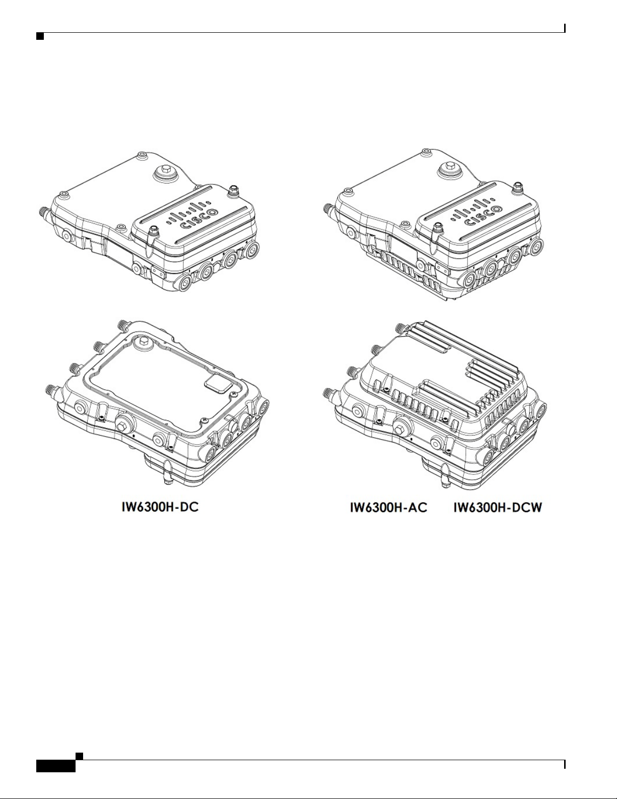
Figure 1-1 IW-6300H Access Points
Chapter 1 Overview
1-2
Cisco Catalyst IW6300 Heavy Duty Series Access Point Hardware Installation Guide
Page 13

Chapter 1 Overview
Hardware Models
REVIEW DRAFT—CISCO CONFIDENTIAL
The model numbers (or part numbers) and configuration for the Cisco Catalyst IW6300 Heavy Duty
Series Access Points are described in the following table.
Ta b l e 1-1 Access Point Model Numbers and Descriptions
Model (or part number)
1
Configuration
IW-6300H-AC-X-K9 IP66 and IP67 rated, hazardous location certified, AC power version.
This model has 4 external antenna ports and contains a 2.4 GHz and 5
GHz radio with an option to configure in centralized, Flexconnect, or
mesh mode and supports AC power source.
IW-6300H-DCW-X-K9 IP66 and IP67 rated, hazardous location certified, DC wide range
power version.
This model has 4 external antenna ports and contains a 2.4 GHz and 5
GHz radio with an option to configure in centralized, Flexconnect, or
mesh mode, and supports 10.8 VDC to 36 VDC power source.
Note The marked DC input range is an absolute range. Do not apply
tolerances.
IW-6300H-DC-X-K9 IP66 and IP67 rated, hazardous location certified, DC power version.
This model has 4 external antenna ports and contains a 2.4 GHz and 5
GHz radio with an option to configure in centralized, Flexconnect, or
mesh mode and supports 44VDC to 57 VDC power source.
Note The marked DC input range is an absolute range. Do not apply
tolerances.
1. The “-X” in the model number represents a regulatory domain for a specific country.
A detailed list of components supported by each access point model is shown in the following table.
Ta b l e 1-2 Components of Each Access Point Model
Customer
1
Product/PID Antenna Ports Ethernet Ports PoE Out Port
IW-6300H-AC-X-K9 Four Type N
Connectors
IW-6300H-DCW-XK9
IW-6300H-DC-X-K9 UPoE, PoE+, DC
• One 100/1000Mbps SFP
for WAN
• One 100/1000Mbps RJ45
for WAN (UPoE or PoE+
in)
• Two 100/1000Mbps RJ45
35.3W Four 1/2”
I/O Ports Power Option
UPoE, PoE+, AC
NPT Ports
(100V to 240V)
UPoE, PoE+, DC
(10.8V to 36V)
(44V to 57V)
2
for LAN (802.11at or
802.3af out)
1. When powered with PoE+, the PoE Out power is not available, The PoE-Out port data link can still be active.
2. For DC SKU, if you want to output 802.3at type 2 PoE out power, DC input must >=51V. If you want to output 802.3af (802.3at type 1) PoE out power,
DC input must >=45V.
For a detailed description of the declarations of conformity and regulatory information for the Cisco
Catalyst IW6300 Heavy Duty Series Access Points, see
Appendix A, “Declarations of Conformity and
Regulatory Information.”
Cisco Catalyst IW6300 Heavy Duty Series Access Point Hardware Installation Guide
1-3
Page 14
Hardware Features
REVIEW DRAFT—CISCO CONFIDENTIAL
Hardware Features
This section describes the hardware features of the IW-6300H series access points.
Connectors
This section describes the access point connectors.
Note The illustrations in this document show all available connections for the access point. Unused
connections are capped with a connector plug to ensure the dust/watertight integrity of the access point.
See Working with the Access Cover for further details.
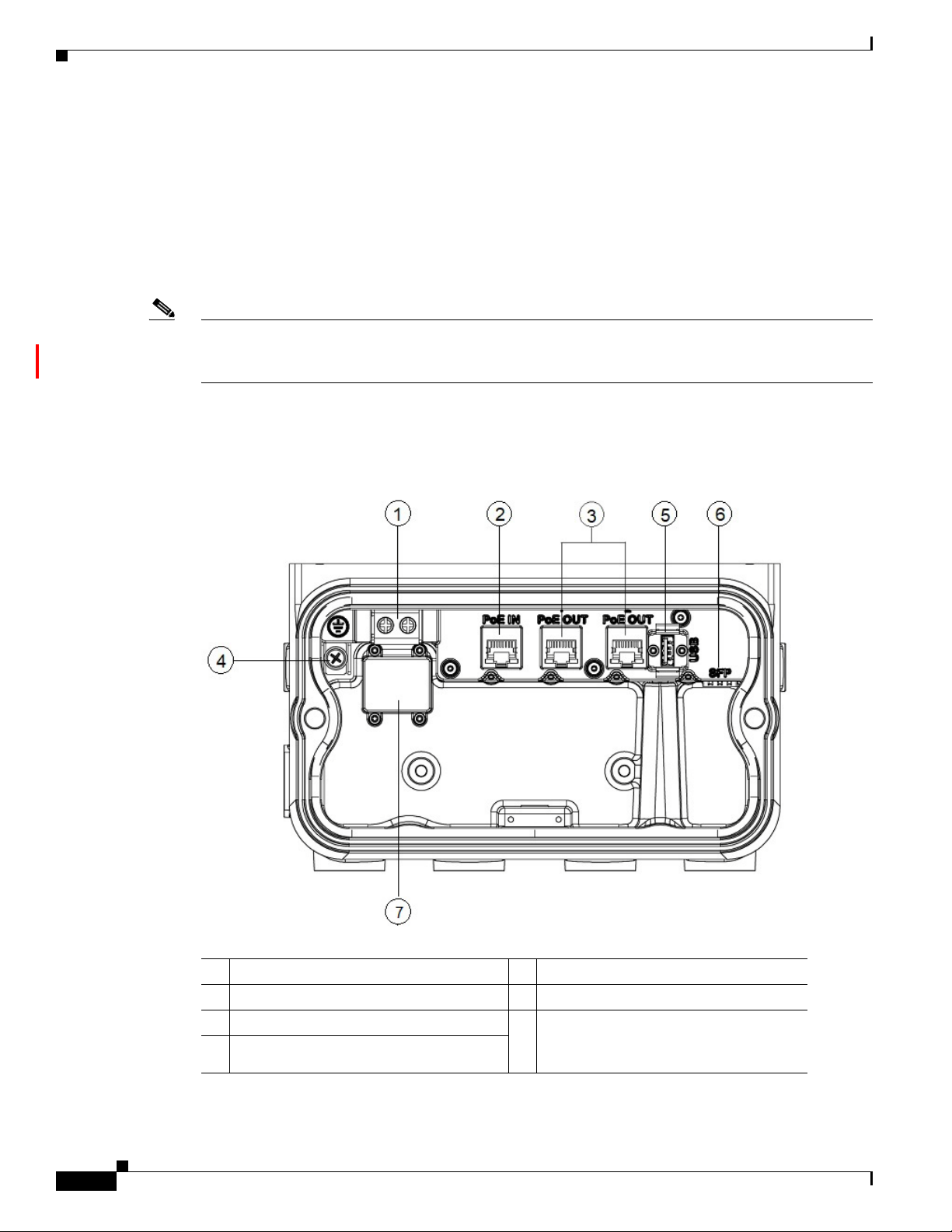
IW-6300H Access Point Internal Connectors
Figure 1-2 IW-6300H Access Point Internal Connectors
Chapter 1 Overview
1-4
1 Power-IN (IW-6300H-DC-X-K9) 5 USB port
2 PoE In port 6 SFP port
3 PoE Out port 7 Terminal block location of
4 Internal ground
Cisco Catalyst IW6300 Heavy Duty Series Access Point Hardware Installation Guide
IW-6300H-AC-X-K9 and
IW-6300H-DCW-X-K9
Page 15
Chapter 1 Overview
REVIEW DRAFT—CISCO CONFIDENTIAL
Console Port and Reset Button
The console port and reset button are under a covering M25 plug located on the side of the access point,
as shown in the following figure.
Figure 1-3 IW-6300H Access Point Console Port and Reset Button
Hardware Features
Power Connector
1 Console port 2 Reset button
Inspect the seal of the plug and properly tighten it at the time of installation, and also every time the plug
is removed and replaced. Tighten the plug to 5-6 lb-ft. If you do not tighten the plug properly, it will not
meet IP66/67 criteria, and may lead to water leaking into the unit.
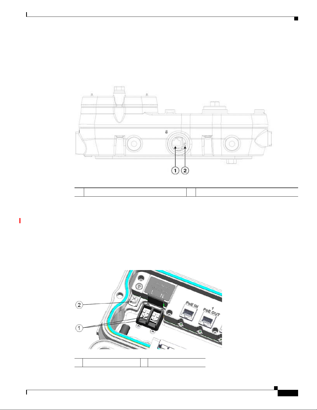
The following figure shows the AC power connector of access point model IW-6300-AC-X-K9.
Figure 1-4 AC Power Connector of Access Point Model IW-6300H-AC-X–K9
1 AC Power-IN 2 Internal ground
Cisco Catalyst IW6300 Heavy Duty Series Access Point Hardware Installation Guide
1-5
Page 16
Hardware Features
Chapter 1 Overview
REVIEW DRAFT—CISCO CONFIDENTIAL
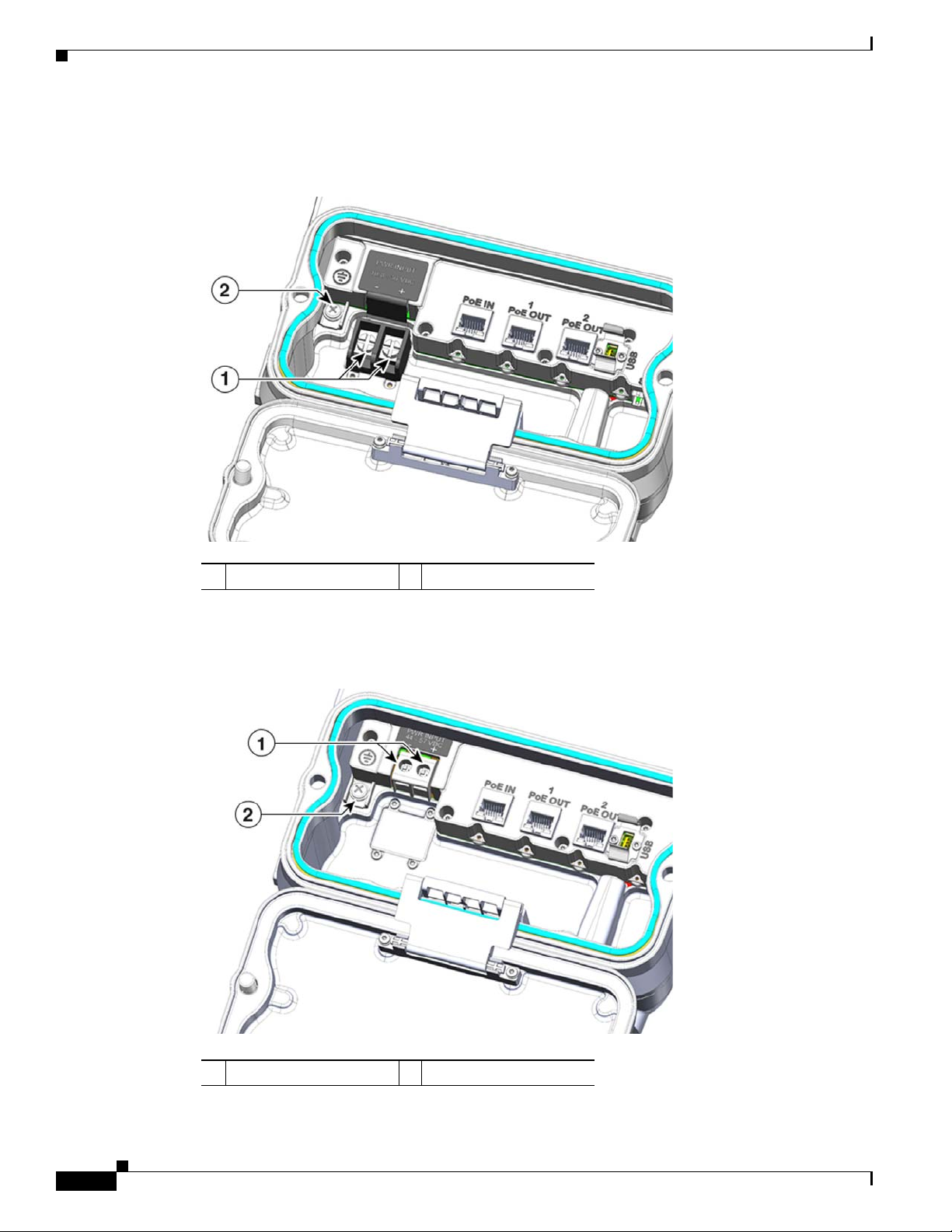
The following figure shows the DC power connector of access point model IW-6300-DCW-X-K9.
Figure 1-5 IW-6300H-DCW-X–K9 Power Connector
1 DC Power-IN 2 Internal ground
The following figure shows the DC power connector of access point model IW-6300-DC-X-K9.
Figure 1-6 IW-6300H-DC-X–K9 Power Connector
1-6
1 DC Power-IN 2 Internal ground
Cisco Catalyst IW6300 Heavy Duty Series Access Point Hardware Installation Guide
Page 17
Chapter 1 Overview
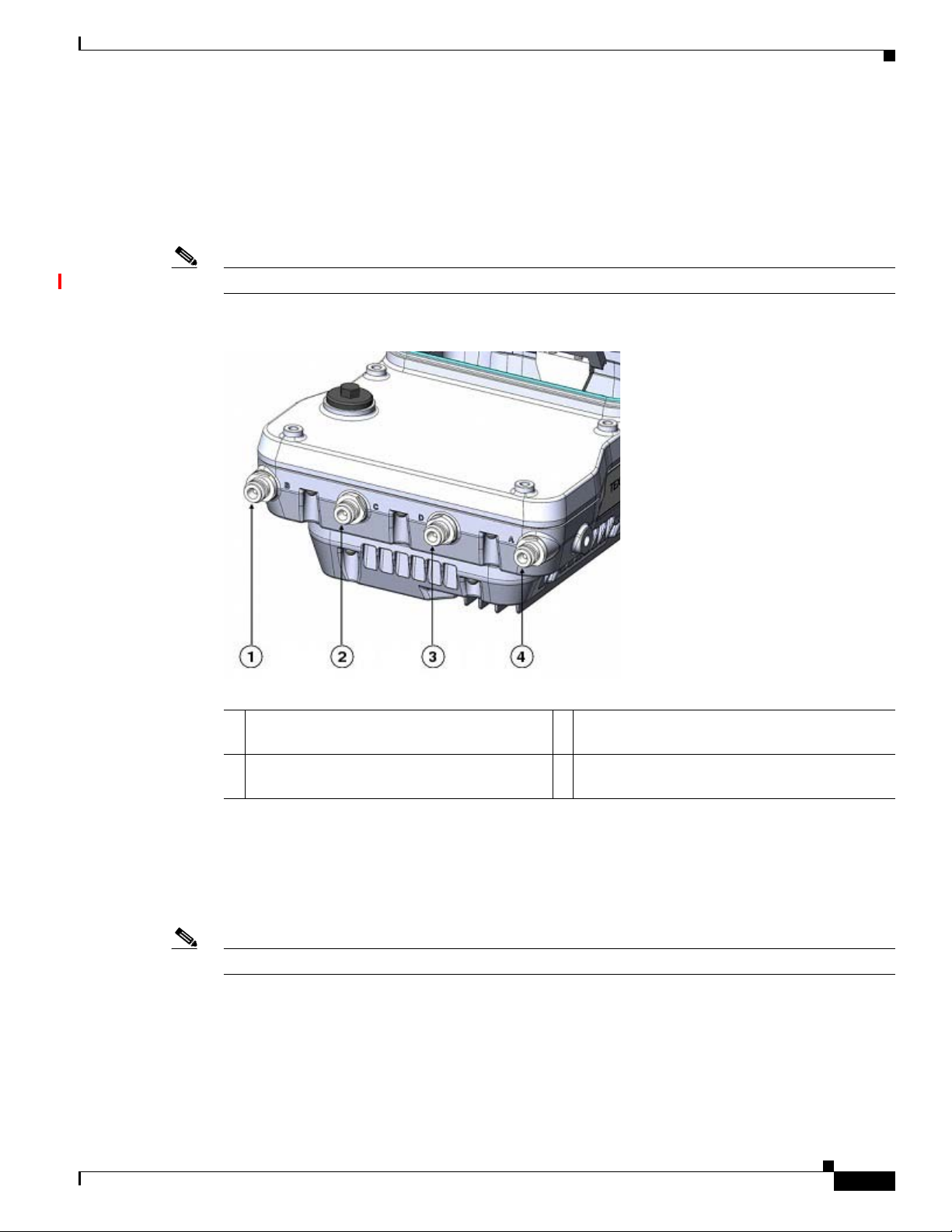
Antenna Ports
Note Antenna caps must be installed when an antenna is not in use (maximum torque range: 6.2-9.7 in-lbs).
Hardware Features
REVIEW DRAFT—CISCO CONFIDENTIAL
The access point antenna N-type connectors are located on the top of each model (see the following
figure). The supported antennas can be directly attached to the access point or remotely located. When
used in a Class 1, Zone 2, Division 2 hazardous location, this equipment must be mounted with proper
RF cables (if required) and electrical wiring methods that comply with the governing electrical codes.
Figure 1-7 Antenna Ports of IW-6300H Access Points
1 Antenna port B - Type N connector Wi-Fi
2.4/5 GHz TX/RX
2 Antenna port C - Type N connector Wi-Fi 5
GHz TX/RX
3 Antenna port D - Type N connector Wi-Fi 5 GHz
TX/RX
4 Antenna port A - Type N connector Wi-Fi 2.4/5
GHz TX/RX
The IW-6300H access point can be configured via software to support dual band or single band antennas.
When configured for dual band antennas, antenna ports A and B are used to support multiple
input/output (MIMO) operation on both 2.4 and 5 GHz radios. When using Cisco Aironet
omnidirectional antennas with Type N male connectors, the antennas can be connected directly to the
access point. If the antennas are remotely located, an appropriate low loss RF cable should be used.
Note Ensure that the antenna band mode is configured before the access point is installed.
When configured for single band antennas, antenna ports A and B support MIMO operation on the 2.4
GHz radio and antenna ports C and D support MIMO operation on the 5 GHz radio. See the Cisco
Wireless LAN Controller Configuration Guide for information on the software configuration.
Cisco Catalyst IW6300 Heavy Duty Series Access Point Hardware Installation Guide
1-7
Page 18

Hardware Features
Use of four omnidirectional antennas attached directly to the Type N connectors is not recommended.
To provide omnidirectional coverage with both 2.4 and 5 GHz radios using directly attached antennas,
it is recommended to configure the IW-6300H in dual band mode, connect two dual band antennas such
as AIR-ANT2547V-N, AIR-ANT2547V-N-HZ, or AIR-ANT2568VG-N to ports A and B, and cap ports
C and D.
The 2 GHz b/g/n radio operates in 2.4 GHz ISM band. It supports channels 1-11 in the US, 1-13 in
Europe, and 1-13 in Japan. It has 2 transmitters with a maximum total output power of 27 dBm for
802.11b/g/n operation. Output power is configurable for 8 levels in 3 dB steps. It has two receivers that
enable maximum-ratio combining (MRC).
The 5 GHz a/n radio operates in the UNII-1 band (5.15-5.25 GHz), UNII-2 band (5.25 - 5.35 GHz),
UNII-2 Extended/ETSI band (5.47 - 5.725 GHz), and the upper ISM band (5.725 - 5.850 GHz). It has
two transmitters with a maximum total output power of 27 dBm depending on the regulatory domain. Tx
power settings will change depending on the regulatory domain. Output power is configurable in 3 dB
steps. Its two receivers enable maximum-ratio combining (MRC).
Power Sources
The Cisco Catalyst IW6300 Heavy Duty Series Access Points support the following power options:
Chapter 1 Overview
REVIEW DRAFT—CISCO CONFIDENTIAL
1. Power over Ethernet by power injector AIR-PWRINJ-60RGD1= and AIR-PWRINJ-60RGD2=
2. AC or DC power
Warning
Power Injectors
IW-6300H-AC-X-K9
85-264V~ maximum, marked 100-240V~, 50-60Hz, 1.3A
IW-6300H-DC-X–K9
44 to 57Vdc, 1.2A
IW-6300H-DCW-X-K9
10.8 to 36Vdc, 5.9A
Note The marked DC input range is an absolute range. Do not apply tolerances.
To reduce risk of electric shock, connect the unit only to DC power source that complies with the
Safety Extra-Low Voltage (SELV) requirements in IEC 60950 based safety standards or ES1
requirements in IEC 62368 based safety standards.
Statement 1033
The IW6300 series access points support the following power injectors:
• AIR-PWRINJ-60RGD1=
• AIR-PWRINJ-60RGD2=
1-8
Caution Power injector AIR-PWRINJ-60RGD is not certified for installation within hazardous locations
environments.
Cisco Catalyst IW6300 Heavy Duty Series Access Point Hardware Installation Guide
Page 19

Chapter 1 Overview
REVIEW DRAFT—CISCO CONFIDENTIAL
For more information about installing the AIR-PWRINJ-60RGDx= power injectors, see Cisco Aironet
Series Power Injectors AIR-PWRINJ-60RGD1= and AIR-PWRINJ-60RGD2= Installation Instructions.
Ethernet (PoE) Ports
The access point supports two Ethernet uplink port (one PoE-In port and one SPF fiber port), and two
PoE-Out ports. The access point Ethernet uplink port uses an RJ-45 connector (with weatherproofing)
to link the access point to the 10BASE-T, 100BASE-T, or 1000BASE-T network. The Ethernet cable is
used to send and receive Ethernet data and to optionally supply inline power from the power injector or
a suitably powered switch port.
Tip The access point senses the Ethernet and power signals and automatically switches internal circuitry to
match the cable connections.
The Ethernet cable must be a shielded outdoor rated Category 5e (CAT5e) or better cable. The access
point senses the Ethernet and power signals and automatically switches internal circuitry to match the
cable connections.
Hardware Features
Fiber Option
Warning
Note SFP modules are not hot-swappable. Plug and unplug the SFP module, the AP will reboot.
Class 1 laser product.
The factory-orderable fiber option provides a fiber input and output capability. Fiber data is transmitted
and received over a single or dual-strand fiber cable, depending on the SFP, which is connected to the
access point using these SFP modules:
• 1000BASE-LX single-mode rugged SFP (GLC-LX-SM-RGD=)
• 1000BASE-SX multi-mode rugged SFP (GLC-SX-MM-RGD=)
• 100BaseBX10-U rugged SFP (GLC-FE-100BX-URGD=)
• 100BASE-FX rugged SFP (GLC-FE-100FX-RGD=)
• 100BASE-LX10 rugged SFP (GLC-FE-100LX-RGD=)
• 1000BASE-T rugged SFP (GLC-T-RGD=)
Client data is passed to the network controller through the fiber connection via a fiber-capable switch or
controller. Configuration information can be found in the controller configuration guide of the switch or
controller you are using.
Statement 1008
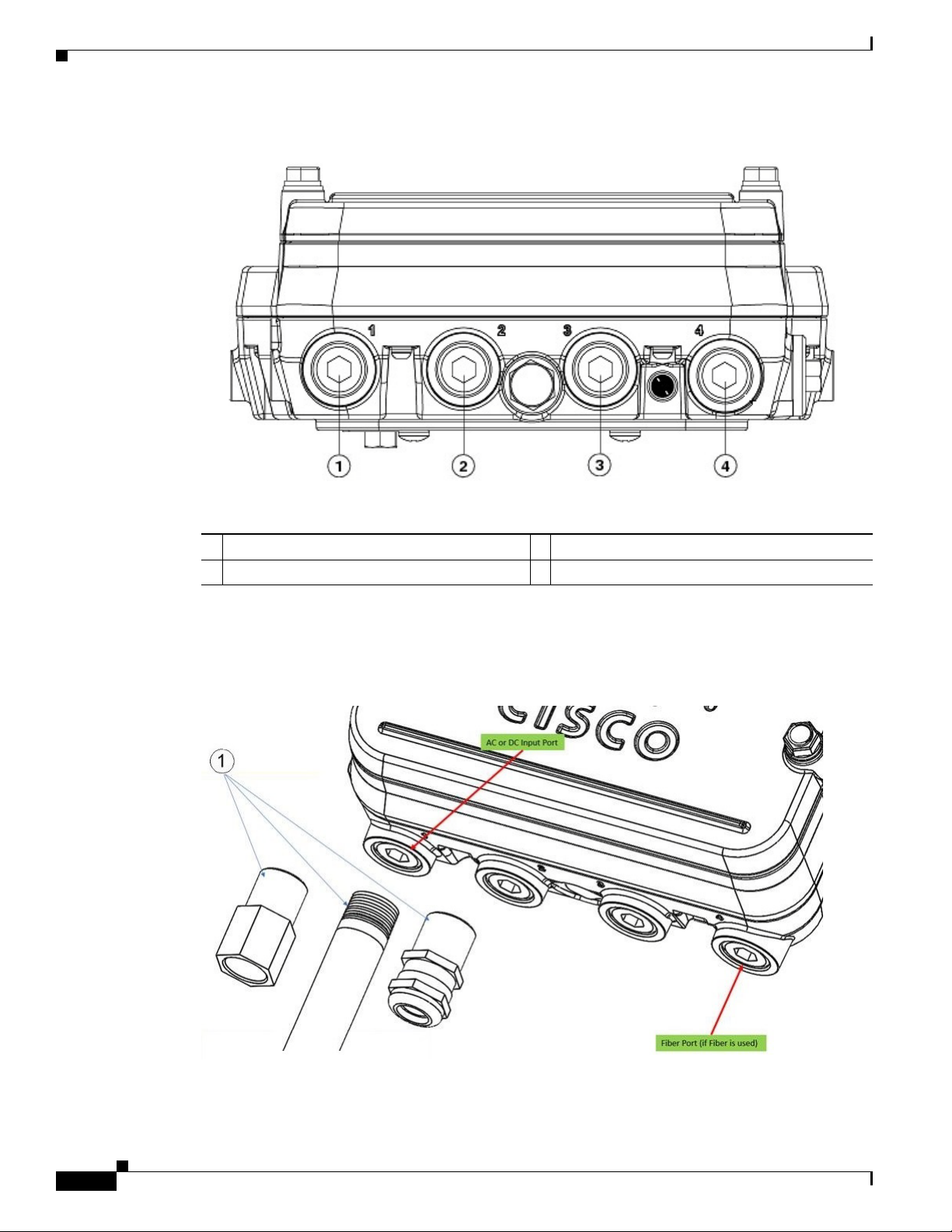
1/2” NPT I/O Ports
The four 1/2-NPT I/O ports are located at the bottom of the access point. These ports are tapered pipe
threads. It is recommended that you use a 3/8” Allen wrench with 13-18" long wrench handle to remove
the port plug.
Cisco Catalyst IW6300 Heavy Duty Series Access Point Hardware Installation Guide
1-9
Page 20
Hardware Features
Chapter 1 Overview
REVIEW DRAFT—CISCO CONFIDENTIAL
Figure 1-8 1/2-NPT I/O Ports
1 AC or DC input 3 PoE port
2 PoE port 4 Fiber port
Loctite 565 Thread Sealant needs to be applied to the threads prior to the installation, as shown in the
following figure. Customer should supply certified 1/2” NPT conduit, gland, or adapter for each port
used for appropriate installation. (For example, Sealcon provides glands and adapters that are certified.
See
https://www.sealconex.com/?ex=9wkuir-fln65y-13897wy-drrs7y.)
1-10
Cisco Catalyst IW6300 Heavy Duty Series Access Point Hardware Installation Guide
Page 21

Chapter 1 Overview
REVIEW DRAFT—CISCO CONFIDENTIAL
Optional Hardware
Depending on the order configuration, the following optional access point hardware may be part of the
shipment:
• Cisco Aironet Antennas
• Pole mount kits (IOT-ACCPMK)
• Band installation tool for pole mount kit (AIR-BAND-INS-TL=)
• Power injector (AIR-PWRINJ-60RGDx=)
• 1000BASE-LX single-mode rugged SFP (GLC-LX-SM-RGD=)
• 1000BASE-SX multi-mode rugged SFP (GLC-SX-MM-RGD=)
• 100BaseBX10-U rugged SFP (GLC-FE-100BX-URGD=)
• 100BASE-FX rugged SFP (GLC-FE-100FX-RGD=)
• 100BASE-LX10 rugged SFP (GLC-FE-100LX-RGD=)
• 1000BASE-T rugged SFP (GLC-T-RGD=)
Hardware Features
Cisco Catalyst IW6300 Heavy Duty Series Access Point Hardware Installation Guide
1-11
Page 22

Hardware Features
Chapter 1 Overview
REVIEW DRAFT—CISCO CONFIDENTIAL
1-12
Cisco Catalyst IW6300 Heavy Duty Series Access Point Hardware Installation Guide
Page 23

REVIEW DRAFT—CISCO CONFIDENTIAL
Before You Begin
This chapter describes what steps you need to take before beginning the installation of your Access Point
and contains the following sections:
• Unpacking the Access Point, page 2-1
• Tools and Hardware, page 2-2
• Warnings, page 2-3
• Safety Information, page 2-3
• Avoiding Damage to Radios in a Testing Environment, page 2-5
• Installation Guidelines, page 2-7
Unpacking the Access Point
CHA P T ER
2
When you are unpacking the access point, do not remove the foam blocks attached to the antenna
connectors. The foam protects the antenna connectors during installation.
To unpack the access point, follow these steps:
Step 1 Open the shipping container and carefully remove the contents.
Step 2 Return all packing materials to the shipping container, and save it.
Step 3 Ensure that all items listed in “Package Contents” section on page 2-1 are included in the shipment. If
any item is damaged or missing, notify your sales representative.
Package Contents
The typical access point package contains the following items:
• Access point
–
–
–
• Mount kit (IOT-ACCPMK)
IW-6300H-AC-X-K9 (AC power model)
IW-6300H-DC-X–K9 (DC power model)
IW-6300H-DCW-X-K9 (DC wide range power model)
Cisco Catalyst IW6300 Heavy Duty Series Access Point Hardware Installation Guide
2-1
Page 24

Tools and Hardware
REVIEW DRAFT—CISCO CONFIDENTIAL
• Ground lug and screws with lock washers
• Weatherization tape and anti-seize compound
Tools and Hardware
The tools and hardware used to install the access point are described in:
• Optional Tools and Hardware, page 2-2
• Optional Tools and Hardware That You Supply, page 2-2
• Pole Installation Hardware and Tools, page 2-3
Optional Tools and Hardware
The optional tools and hardware that can be obtained from Cisco are:
• Optional power injector (AIR-PWRINJ-60GRDx=)
• Antennas, 2.4/5-GHz
Chapter 2 Before You Begin
• Optional banding strap tool (BAND IT) (AIR-BAND-INST-TL=)
Optional Tools and Hardware That You Supply
Tools and materials that are user-supplied are:
• 1/2” or 13-mm socket wrench, used to open the Access Cover and to attach the mounting bracket
• #2 Phillips or Flat screw driver to clamp wire terminal and ground terminal
• 3/8” Allen wrench with 13-18" long wrench handle to remove 1/2” NPT port plugs
• Loctite 565 Thread Sealant for 1/2” NPT Ports
• 6-AWG copper ground wire
• Ethernet RJ-45 connector and installation tool
• Optional ground rod, as required by local regulations
• Optional ladder, power lift, rope, or other tools as required
• ESD-preventive cord and wrist strap.
• Wire-stripping tools for stripping 14- and 18-gauge wires
• Crimping tool
If installed in a hazardous location, please note the additional items (see Product Document of
Compliance for further details)
• ATEX certified Armored cable for routing in conduit
2-2
• Customer supplied ATEX certified 1/2” NPT conduit (rigid or flex), or ATEX certified cable gland
or barrier gland for each connection
• ATEX-certified AC or DC power cable, based on the AP model ordered
Cisco Catalyst IW6300 Heavy Duty Series Access Point Hardware Installation Guide
Page 25

Chapter 2 Before You Begin
REVIEW DRAFT—CISCO CONFIDENTIAL
Pole Installation Hardware and Tools
To install the access point on a vertical or horizontal metal, wood, or fiberglass pole, you need the
following additional hardware and tools:
• Customer banding strap tool (BAND IT)—(AIR-BAND-INST-TL=)
• Customer-supplied 13-mm and box-end wrench or socket set
Warnings
Warnings
Warning
Caution The installer is responsible for obtaining any required local or national safety inspections of the
Warning
Warning
Warning
IMPORTANT SAFETY INSTRUCTIONS
This warning symbol means danger. You are in a situation that could cause bodily injury. Before you
work on any equipment, be aware of the hazards involved with electrical circuitry and be familiar
with standard practices for preventing accidents. Use the statement number provided at the end of
each warning to locate its translation in the translated safety warnings that accompanied this device.
Statement 1071
SAVE THESE INSTRUCTIONS
structural integrity of the installation by the local authority/inspection department.
This equipment must be externally grounded using a customer-supplied ground wire before power is
applied. Contact the appropriate electrical inspection authority or an electrician if you are uncertain
that suitable grounding is available.
Read the installation instructions before connecting the system to the power source.
Ultimate disposal of this product should be handled according to all national laws and regulations.
Statement 1040
Statement 366
Statement 1004
Safety Information
Follow the guidelines in this section to ensure proper operation and safe use of the access point.
Cisco Catalyst IW6300 Heavy Duty Series Access Point Hardware Installation Guide
2-3
Page 26

Safety Information
REVIEW DRAFT—CISCO CONFIDENTIAL
FCC Safety Compliance Statement
The FCC, with its action in ET Docket 96-8, has adopted a safety standard for human exposure to RF
electromagnetic energy emitted by FCC-certified equipment. When used with approved Cisco Aironet
antennas, Cisco Aironet products meet the uncontrolled environmental limits found in OET-65 and ANSI
C95.1, 1991. Proper operation of this radio device according to the instructions in this publication results
in user exposure substantially below the FCC recommended limits.
Safety Precautions
Chapter 2 Before You Begin
Warning
Warning
Warning
Warning
Warning
Warning
The AC power supply has double pole/neutral fusing.
In order to comply with FCC radio frequency (RF) exposure limits, antennas should be located at a
minimum of 7.9 inches (20 cm) or more from the body of all persons.
Do not work on the system or connect or disconnect cables during periods of lightning activity.
Statement 1001
Read the installation instructions before connecting the system to the power source.
This unit is intended for installation in restricted access areas. A restricted access area can be
accessed only through the use of a special tool, lock and key, or other means of security.
1017
This equipment must be grounded. Never defeat the ground conductor or operate the equipment in the
absence of a suitably installed ground conductor. Contact the appropriate electrical inspection
authority or an electrician if you are uncertain that suitable grounding is available.
Statement 188
Statement 332
Statement 1004
Statement
Statement 1024
2-4
Warning
Warning
Warning
Cisco Catalyst IW6300 Heavy Duty Series Access Point Hardware Installation Guide
Only trained and qualified personnel should be allowed to install, replace, or service this equipment.
Statement 1030
Ultimate disposal of this product should be handled according to all national laws and regulations.
Statement 1040
When installing or replacing the unit, the ground connection must always be made first and
disconnected last.
Statement 1046
Page 27

Chapter 2 Before You Begin
Avoiding Damage to Radios in a Testing Environment
REVIEW DRAFT—CISCO CONFIDENTIAL
Warning
Warning
Warning
To prevent the system from overheating, do not operate it in an area that exceeds the maximum
recommended ambient temperature of:
75° C (167° F)
Do not locate the antenna near overhead power lines or other electric light or power circuits, or
where it can come into contact with such circuits. When installing the antenna, take extreme care
not to come into contact with such circuits, because they may cause serious injury or death. For
proper installation and grounding of the antenna, please refer to national and local codes (for
example, U.S.:NFPA 70, National Electrical Code, Article 810, Canada: Canadian Electrical Code,
Section 54).
Installation of the equipment must comply with local and national electrical codes.
Statement 1047
Statement 1052
Statement 1074
For safety and to achieve a good installation, please read and follow these safety precautions:
• Select your installation site with safety, as well as performance in mind. Remember: electric power
lines and phone lines look alike. For safety, assume that any overhead line can kill.
• Call your electric power company. Tell them your plans, and ask them to come look at your proposed
installation.
• Plan your installation carefully and completely before you begin. Successful raising of a mast or
tower is largely a matter of coordination. Each person should be assigned to a specific task and
should know what to do and when to do it. One person should be in charge of the operation to issue
instructions and watch for signs of trouble.
• When installing the access point and antennas, remember:
–
Do not use a metal ladder.
–
Do not work on a wet or windy day.
–
Do dress properly—shoes with rubber soles and heels, rubber gloves, long sleeved shirt or
jacket.
• Use a rope to lift the access point. If the assembly starts to drop, get away from it and let it fall.
• If any part of the antenna system should come in contact with a power line, do not touch it or try to
remove it yourself. Call your local power company. They will remove it safely.
If an accident should occur, call for qualified emergency help immediately.
Avoiding Damage to Radios in a Testing Environment
The radios on outdoor units (bridges) have higher transmit power levels than radios on indoor units
(access points). When you test high-power radios in a link, you must avoid exceeding the maximum
receive input level for the receiver. At levels above the normal operating range, packet error rate (PER)
performance is degraded. At even higher levels, the receiver can be permanently damaged. To avoid
receiver damage and PER degradation, you can use one of the following techniques:
• Separate the omnidirectional antennas by at least 2 ft (0.6 m) to avoid receiver damage or by at least
25 ft (7.6 m) to avoid PER degradation.
Cisco Catalyst IW6300 Heavy Duty Series Access Point Hardware Installation Guide
2-5
Page 28

Avoiding Damage to Radios in a Testing Environment
REVIEW DRAFT—CISCO CONFIDENTIAL
Note These distances assume free space path loss and are conservative estimates. Required separation
distances for damage and performance degradation levels in actual deployments are less if
conditions are not non-line-of-sight.
• Reduce the configured transmit power to the minimum level.
• Use directional antennas, and keep them away from each other.
• Cable the radios together using a combination of attenuators, combiners, or splitters to achieve a total
attenuation of at least 60 dB.
For a radiated test bed, the following equation describes the relationships among transmit power, antenna
gain, attenuation, and receiver sensitivity:
txpwr + tx gain + rx gain - [attenuation due to antenna spacing] < max rx input level
Where:
txpwr = Radio transmit power level
tx gain = transmitter antenna gain
rx gain = receiver antenna gain
For a conducted test bed, the following equation describes the relationships among transmit power,
antenna gain, and receiver sensitivity:
txpwr - [attenuation due to coaxial components] < max rx input level
Chapter 2 Before You Begin
Caution Under no circumstances should you connect the antenna port from one access point to the antenna port
of another access point without using an RF attenuator. If you connect antenna ports, you must not
exceed the maximum survivable receive level of 0 dBm. Never exceed 0 dBm, or damage to the access
point can occur. It is recommended to keep the received signal strength at or below -30 dBm to avoid
degraded PER. Using attenuators, combiners, and splitters having a total of at least 60 dB of attenuation
ensures that the receiver is not damaged and that PER performance is not degraded.
Safety Precautions When Installing Antennas
Warning
Do not locate the antenna near overhead power lines or other electric light or power circuits, or
where it can come into contact with such circuits. When installing the antenna, take extreme care
not to come into contact with such circuits, as they may cause serious injury or death. For proper
installation and grounding of the antenna, please refer to national and local codes (e.g. U.S.: NFPA 70,
National Electrical Code, Article 810, Canada: Canadian Electrical Code, Section 54).
1. Before you install an antenna, contact your Cisco account representative to explain which mounting
method to use for the size and type of antenna that you are about to install.
2. Select your installation site with safety, as well as performance, in mind. Remember that electric
power lines and phone lines look alike. For your safety, assume that any overhead line can kill you.
3. Contact your electric power company. Tell them your plans and ask them to come look at your
proposed installation.
Statement 280
2-6
4. Plan your installation carefully and completely before you begin. Each person involved in an
installation should be assigned to a specific task and should know what to do and when to do it. One
person should be in charge of the operation to issue instructions and watch for signs of trouble.
5. When installing your antenna, follow these guidelines:
Cisco Catalyst IW6300 Heavy Duty Series Access Point Hardware Installation Guide
Page 29

Chapter 2 Before You Begin
REVIEW DRAFT—CISCO CONFIDENTIAL
–
Do not use a metal ladder.
–
Do not work on a wet or windy day.
–
Do dress properly—wear shoes with rubber soles and heels, rubber gloves, and a long-sleeved
shirt or jacket.
6. If the assembly starts to drop, move away from it and let it fall. Because the antenna, mast, cable,
and metal guy wires are all excellent conductors of electrical current, even the slightest touch of any
of these parts to a power line completes an electrical path through the antenna and the installer.
7. If any part of the antenna system should come in contact with a power line, do not touch it or try to
remove it yourself. Call your local power company to have it removed safely.
8. If an accident should occur with the power lines, call for qualified emergency help immediately.
Installation Guidelines
Because the access point is a radio device, it is susceptible to common causes of interference that can
reduce throughput and range. Follow these basic guidelines to ensure the best possible performance:
• For information on planning and initially configuring your Cisco Mesh network, refer to the Cisco
Wireless Mesh Access Points, Design and Deployment Guide.
Installation Guidelines
Note To calculate path loss and to determine how far apart to install access points, consult an RF planning
Site Surveys
• Review the FCC guidelines for installing and operating outdoor wireless LAN devices.
• Perform a site survey before beginning the installation.
• Install the access point in an area where structures, trees, or hills do not obstruct radio signals to and
from the access point.
• The access points can be installed at any height, but best throughput is achieved when all the access
points are mounted at the same height. Cisco recommends installing the access points no higher than
40 feet to allow support for wireless clients on the ground.
expert.
Every network application is a unique installation. Before installing multiple access points, you should
perform a site survey to determine the optimum use of networking components and to maximize range,
coverage, and network performance.
Consider the following operating and environmental conditions when performing a site survey:
• Data rates—Sensitivity and range are inversely proportional to data bit rates. The maximum radio
range is achieved at the lowest workable data rate. A decrease in receiver sensitivity occurs as the
radio data increases.
• Antenna type and placement—Proper antenna configuration is a critical factor in maximizing radio
range. As a general rule, range increases in proportion to antenna height. However, do not place the
antenna higher than necessary, because the extra height also increases potential interference from
other unlicensed radio systems and decreases the wireless coverage from the ground.
• Physical environment—Clear or open areas provide better radio range than closed or filled areas.
Cisco Catalyst IW6300 Heavy Duty Series Access Point Hardware Installation Guide
2-7
Page 30

Installation Guidelines
REVIEW DRAFT—CISCO CONFIDENTIAL
• Obstructions—Physical obstructions such as buildings, trees, or hills can hinder performance of
wireless devices. Avoid locating the devices in a location where there is an obstruction between the
sending and receiving antennas.
• Applications and type of devices to be used on the WLAN.
Before Beginning the Installation
Before you begin the installation process:
• Ensure that a site survey has been performed.
• Ensure that your network infrastructure devices are operational and properly configured.
• Ensure that your controllers are connected to switch trunk ports.
• Ensure that your switch is configured with untagged access ports for connecting your access points.
• Ensure that a DHCP server with Option 43 configured is reachable by your access points, or
manually configure the controller information in the access point (for additional information, refer
to the software configuration guide).
• Become familiar with the access point installation components.
Chapter 2 Before You Begin
2-8
Cisco Catalyst IW6300 Heavy Duty Series Access Point Hardware Installation Guide
Page 31

REVIEW DRAFT—CISCO CONFIDENTIAL
Installing the Access Points
This chapter describes how to install the access point and contains the following sections:
• Mounting on a Wall or a Pole, page 3-1
• Working with the Access Cover, page 3-14
• Installing External Antennas, page 3-15
• Grounding the Access Point, page 3-16
• Using the Reset Button, page 3-18
• Powering the Access Point, page 3-18
• Performing Maintenance, page 3-25
Mounting on a Wall or a Pole
CHA P T ER
3
This section provides instructions for the physical installation of your access points. Personnel installing
the access point must understand wireless access points and bridging techniques and grounding methods.
Caution All installation methods for mounting an access point on any wall surface is subject to the acceptance of
local jurisdiction.
Installation Option
The Cisco Catalyst IW6300 Heavy Duty Series Access Points are installed using the pole mount
installation kit (IOT-ACCPMK), which is used for pole or wall installations.
Warning
Warning
Only trained and qualified personnel should be allowed to install, replace, or service this equipment.
Statement 1030
Installation of the equipment must comply with local and national electrical codes.
Refer to these sections for installation details:
• Access Point Mounting Orientation, page 3-2
Statement 1074
Cisco Catalyst IW6300 Heavy Duty Series Access Point Hardware Installation Guide
3-1
Page 32

Mounting on a Wall or a Pole
REVIEW DRAFT—CISCO CONFIDENTIAL
• Mounting the Access Point on a Wall, page 3-3
• Mounting the Access Point on a Pole, page 3-6
Access Point Mounting Orientation
When mounting an access point on a horizontal or vertical surface, you must ensure that the access point
is oriented with the system LED pointing down. This positioning allows the LEDs to be visible to
someone on the ground below the access point.
You must also ensure the access point is mounted with the hinged access cover facing out.
Note Omnidirectional antennas are vertically polarized and should be mounted vertically.
The following figures show the dimension of the access point:
Figure 3-1 Unit Dimension - Front
Chapter 3 Installing the Access Points
3-2
Cisco Catalyst IW6300 Heavy Duty Series Access Point Hardware Installation Guide
Page 33

Chapter 3 Installing the Access Points
REVIEW DRAFT—CISCO CONFIDENTIAL
Figure 3-2 Unit Dimension - Side
Mounting on a Wall or a Pole
Mounting the Access Point on a Wall
The optional pole mount kit contains a mounting bracket for wall mounting. You can use the mounting
bracket as a template to mark the positions of the mounting holes for your installation. You then install
the mounting plate, and attach the access point when you are ready. The following table lists the material
that you will need to provide in addition to the pole mount kit.
Ta b l e 3-1 Material Needed to Mount Access Point to a Vertical Wall
Materials Required In Kit
Ground lug and screws (provided with access point) Ye s
Crimping tool for ground lug No
Four M8 or 5/16 in. (31 mm) screws No
Four wall anchors (specified for wall material) No
Drill bit for wall anchors No
Electric drill and standard screwdriver No
#6-AWG ground wire No
Cisco Catalyst IW6300 Heavy Duty Series Access Point Hardware Installation Guide
3-3
Page 34

Mounting on a Wall or a Pole
Table 3-1 Material Needed to Mount Access Point to a Vertical Wall (continued)
Materials Required In Kit
Shielded outdoor-rated Ethernet (CAT5e or better) cable No
Grounding block No
Grounding rod No
13-mm box-end wrench or socket set No
Caution The mounting surface, attaching screws, and optional wall anchors must be able to support a 50-lb
(22.7 kg) static weight.
The mounting bracket can be used as a template to mark the screw hole locations. To mount the access
point on a vertical wall, follow these instructions:
Step 1 Use the mounting bracket as a template to mark four screw hole locations on your mounting surface. You
can optionally use the individual mounting holes or the mounting slots.
Chapter 3 Installing the Access Points
REVIEW DRAFT—CISCO CONFIDENTIAL
Figure 3-3 Mounting Bracket Dimension
3-4
Cisco Catalyst IW6300 Heavy Duty Series Access Point Hardware Installation Guide
Page 35

Chapter 3 Installing the Access Points
REVIEW DRAFT—CISCO CONFIDENTIAL
Figure 3-4 Screw Hole Locations on the Mounting Bracket
Mounting on a Wall or a Pole
1 Mounting slots 3 Hands-free attach point
2 Mounting holes 4 Second support bolt hole
Step 2 Use four customer-supplied screws and optional screw anchors to attach the mounting plate to the
mounting surface.
Note If necessary, use suitable screw anchors and an exterior-grade plywood backboard to mount the
access point to stucco, cement, or drywall.
Step 3 Screw a M8 x16 bolt in the top support bolt hole on each side the access point. Do not screw the bolt all
the way in; leave approximately a 0.25 inch (0.635 cm) space.
Step 4 Position the two bolts on the access point onto the hands-free attach points on each side of the mounting
bracket. Ensure that the access point cover is facing out. Never leave the access point unattended until
fully installed.
Cisco Catalyst IW6300 Heavy Duty Series Access Point Hardware Installation Guide
3-5
Page 36

Mounting on a Wall or a Pole
Figure 3-5 Support Bolt Installation
Chapter 3 Installing the Access Points
REVIEW DRAFT—CISCO CONFIDENTIAL
1 Top support M8 x16 bolt 2 Second support M8x16 bolt
Step 5 Screw a M8 x16 bolt (with flat and lock washers) into the second bolt hole on each side of the access
point.
Step 6 Ensure that the front of the access point is vertical, and tighten the four bolts to 13 to 15 ft lbs
(17.6 to 20.3 Nm).
Step 7 When using the Cisco Aironet Dual-Band Omnidirectional Antennas, connect them to the access point.
Hand-tighten the antennas to the access point.
Step 8 Continue with Grounding the Access Point and Powering the Access Point.
Mounting the Access Point on a Pole
When installing an access point on a vertical pole, you should use the optional Cisco pole mount kit. The
kit supports metal, wood, or fiberglass poles from 2 to 16 inches in diameter.
Assembling the Pole Clamp Bracket and the Mounting Bracket
The pole mount kit contains several parts that you must assemble prior to mounting on a pole. First you
need to assemble two strap brackets on the pole clamp bracket that are positioned for the pole diameter
you are using to mount the access point. The following figure illustrates the pole diameter indicators and
bolt holes on the pole clamp bracket.
3-6
Cisco Catalyst IW6300 Heavy Duty Series Access Point Hardware Installation Guide
Page 37

Chapter 3 Installing the Access Points
REVIEW DRAFT—CISCO CONFIDENTIAL
Figure 3-6 Pole Clamp Bracket Adjustment Hole Locations
Mounting on a Wall or a Pole
1 Pole size indicators
• 2 to 6 inches (5.08 cm to 15.24 cm)
• 6 to 11 inches (15.24 cm to 27.94
2 Bolt holes for pole diameters
(11 to 16 inches (27.94 cm to 40.64 cm)
indicated)
cm)
• 11 to 16 inches (27.94 cm to 40.64
cm)
To assemble the pole clamp bracket, follow these steps:
Step 1 Position the strap brackets on the pole clamp bracket for the pole diameter you are using and secure each
strap bracket with two M8 x16 bolts (with lock washers). Tighten the bolts to 13 to 15 ft lbs (17.6 to 20.3
Nm).
Cisco Catalyst IW6300 Heavy Duty Series Access Point Hardware Installation Guide
3-7
Page 38

Mounting on a Wall or a Pole
Figure 3-7 Assembled Pole Clamp Bracket and Strap Brackets
Chapter 3 Installing the Access Points
REVIEW DRAFT—CISCO CONFIDENTIAL
Step 2 Screw the M8 nut onto the pole clamp bracket support bolt, and tighten just enough to prevent the bolt
Step 3 Go to Pole Mounting.
Pole Mounting
1 M8 x1.25x16 bolts (with lock washers) 2 Pole clamp bracket
3 Strap bracket (shown positioned for 11 to 16 inch diameter pole)
from falling off.
To mount your access point on a vertical pole, you need to install two metal bands around the pole to
support the access point. This process requires extra tools and material not provided in the pole mount
kit (see the following table).
3-8
Cisco Catalyst IW6300 Heavy Duty Series Access Point Hardware Installation Guide
Page 39

Chapter 3 Installing the Access Points
REVIEW DRAFT—CISCO CONFIDENTIAL
Ta b l e 3-2 Materials Needed to Mount Access Point on a Pole
Mounting Method Materials Required In Kit
Vertical or streetlight pole Two 0.75-in (1.9 cm) stainless steel bands Yes
To mount the access point onto a vertical pole, follow these steps:
Step 1 Select a mounting location on the pole to mount the access point. You can attach the access point to any
pole from 2 to 16 inch (5.1 to 40.6 cm) in diameter.
Step 2 For poles larger than 3.5 inch (8.9 cm), mount the pole clamp bracket assembly to a pole using two metal
straps. Following the instructions provided with the banding strap tool (BAND IT)
(AIR-BAND-INST-TL=), loop each metal strap twice through the slots on the strap bracket.
Mounting on a Wall or a Pole
Banding strap tool (BAND IT) (Cisco
No
AIR-BAND-INST-TL=)
Ground lug (provided with access point) Yes
Crimping tool for ground lug, Panduit CT-720 with
No
CD-720-1 die (http://onlinecatalog.panduit.com)
#6 AWG ground wire No
Caution Do not place the metal straps in the large open area between the pole clamp bracket and the strap brackets
because this does not properly secure the access point.
Figure 3-8 Clamp Bracket Assembly Mounted on Poles Larger than 3.5 inch (8.9 cm)
23
1
231418
2
3
4
1 Pole clamp bracket 3 Metal mounting strap
2 Strap slot in strap bracket 4 Pole
Cisco Catalyst IW6300 Heavy Duty Series Access Point Hardware Installation Guide
3-9
Page 40

Mounting on a Wall or a Pole
Step 3 For pole diameters of 3.5 inch (8.9 cm) or less, mount the pole clamp bracket assembly to a pole using
two metal straps looped through the space between the pole clamp bracket and the strap brackets to
provide maximum holding strength for extreme environments. Following the instructions provided with
the banding strap tool (BAND IT) (AIR-BAND-INST-TL=), loop each metal strap twice.
Caution Do not place the metal straps in the large open area between the pole clamp bracket and the strap brackets
because this does not properly secure the access point.
Step 4 Position the pole clamp bracket on the pole as needed before tightening the metal bands.
Note When the metal bands are tightened to the full tension, the pole clamp bracket cannot be adjusted
Step 5 Tighten the metal bands using the banding strap tool (BAND IT) (Cisco AIR-BAND-INST-TL=) by
following the operating instructions in the box with the tool. Ensure that the metal bands are as tight as
possible.
Step 6 Place the mounting bracket onto the pole clamp bracket support bolt.
Step 7 Install four M8 x16 bolts (with flat and lock washers) into the bolt holes.
Step 8 Hand-tighten the bolts and the nut (do not overtighten).
Chapter 3 Installing the Access Points
REVIEW DRAFT—CISCO CONFIDENTIAL
unless the metal bands are cut or disassembled.
Step 9 Adjust the top edge of the mounting bracket until it is horizontal and tighten the bolts and the flange nut
to 13 to 15 ft lbs (17.6 to 20.3 Nm).
Figure 3-9 Attach the Mount Bracket
3-10
1 M8 x 16 bolts 2 Flange nut
Cisco Catalyst IW6300 Heavy Duty Series Access Point Hardware Installation Guide
Page 41

Chapter 3 Installing the Access Points
REVIEW DRAFT—CISCO CONFIDENTIAL
Step 10 Screw a M8 x16 bolt (without a flat or lock washer) in the top support bolt hole on each side the access
point. Do not screw the bolt all the way in. Leave a gap of approximately 0.25 inch (0.635 cm).
Step 11 Position the two bolts on the access point onto the hands-free attach point of the mounting bracket.
Note The access point should be positioned with the LEDs on the bottom to allow viewing from the
ground and with the hinged cover facing out.
Figure 3-10 Assembling Access Point to Hands-Free Attach Point with Top Support Bolts
Mounting on a Wall or a Pole
1 Top Support M8 x16 bolt hole 3 Hands-free attach point
2 Second M8 x16 bolt hole
Cisco Catalyst IW6300 Heavy Duty Series Access Point Hardware Installation Guide
3-11
Page 42

Mounting on a Wall or a Pole
Step 12 Screw a M8 x16 bolt (with flat and lock washers) into the second bolt hole on each side of the access
point.
Figure 3-11 Second Support Bolt Installation
Chapter 3 Installing the Access Points
REVIEW DRAFT—CISCO CONFIDENTIAL
3-12
1 M8 x16 bolt
Cisco Catalyst IW6300 Heavy Duty Series Access Point Hardware Installation Guide
Page 43

Chapter 3 Installing the Access Points
REVIEW DRAFT—CISCO CONFIDENTIAL
Step 13 Ensure that the front of the access point is vertical, and tighten the four bolts to 13 to 15 ft lbs
(17.6 to 20.3 Nm).
Figure 3-12 Assembled Access Point Hanging in Mounting Bracket
Mounting on a Wall or a Pole
1 Access point 3 Pole (wood, metal, or fiberglass)
2 to 16 in. (5.1 to 40.6 cm) diameter
2 Mount bracket 4 Stainless steel mounting straps
Step 14 When using the Cisco Aironet Dual-Band Omnidirectional Antennas, connect them to the access point.
Hand-tighten the antennas to the access point.
Step 15 Continue with Grounding the Access Point and Powering the Access Point.
Cisco Catalyst IW6300 Heavy Duty Series Access Point Hardware Installation Guide
3-13
Page 44

Working with the Access Cover
REVIEW DRAFT—CISCO CONFIDENTIAL
Working with the Access Cover
This section details opening and closing the access cover of the access point.
Opening the Access Cover
Caution The access cover must not be opened unless the area is considered non-hazardous and the AP has been
powered off.
You need to open the access cover to access the AC or DC terminal block, the Ethernet ports, and when
you are installing the fiber-optic SFP module.
To open the access cover, follow these steps:
Step 1 Use 0.5-in (13-mm) box-end wrench or socket set to unscrew the two bolts on the front cover of the unit.
Only unscrew the bolts about 2 turns until they are easily turned by hand, and the bolts are resting on
springs.
Chapter 3 Installing the Access Points
Figure 3-13 Access Point Front View of Cover
1 M8 bolts
Step 2 The cover is hinged on the bottom, and the bolts are designed to be captive. Carefully open the cover and
fold the cover back.
3-14
Cisco Catalyst IW6300 Heavy Duty Series Access Point Hardware Installation Guide
Page 45

Chapter 3 Installing the Access Points
REVIEW DRAFT—CISCO CONFIDENTIAL
Closing the Access Cover
To close the access cover, follow these steps:
Step 1 Ensure that O-ring sealing surface is free of debris and that O-ring is undamaged and fully contained in
groove.
Step 2 When closing the access cover, be careful not to pinch internal wires.
Step 3 Carefully position the cover flush with all sides of the access point, then slowly hand-tighten each bolt.
Step 4 When all bolts are hand-tightened, use a 13-mm closed-end wrench or socket to partially tighten the bolts
in the tightening sequence. Tighten each bolt to 3 to 4 ft lbs (0.34 to 0.45 Nm).
Step 5 Repeat Step 3 using the same tightening sequence to fully tighten each bolt to 6 to 7 ft lbs
(0.68 to 0.79 Nm).
Installing External Antennas
Installing External Antennas
Note When operating in the 5GHz UNII-1 band, all Omni Directional antennas should be installed vertically,
and all directional antennas should be installed with the main beam aimed parallel to or tilted down
toward the horizon.
The following table shows the external antennas supported by the IW-6300H access point and provides
required quantities for each model.
Ta b l e 3-3 IW-6300H Access Point Supported External Antennas
Frequency
Product ID
AIR-ANT2547V-N 2.4 / 5 GHz 4 / 7 dBi Omnidirectional, vertically polarized, white
AIR-ANT2547VG-N 2.4 / 5 GHz 4 / 7 dBi Omnidirectional, vertically polarized, gray
AIR-ANT2547V-N-HZ 2.4 / 5 GHz 4 / 7 dBi Omnidirectional, vertically polarized,
AIR-ANT2568VG-N 2.4 / 5 GHz 6 / 8 dBi Omnidirectional, vertically polarized, gray
AIR-ANT2588P3M-N= 2.4 / 5 GHz 8 / 8 dBi Directional, dual polarized, 3 port
AIR-ANT2513P4M-N= 2.4 / 5 GHz 13 / 13 dBi Directional, dual polarized, 4 port
AIR-ANT2450V-N= 2.4 GHz 5 dBi Omnidirectional, vertically polarized, white
AIR-ANT2450V-N-HZ= 2.4 GHz 5 dBi Omnidirectional, vertically polarized,
AIR-ANT2450VG-N= 2.4 GHz 5 dBi Omnidirectional, vertically polarized, gray
AIR-ANT2450HG-N= 2.4 GHz 5 dBi Omnidirectional, horizontally polarized,
AIR-ANT2480V-N= 2.4 GHz 8 dBi Omnidirectional, vertically polarized
AIR-ANT2413P2M-N= 2.4 GHz 13 dBi Directional, dual polarized, 2 port
Band
Gain Typ e
white, for Hazardous Locations
white, for Hazardous Locations
gray
Cisco Catalyst IW6300 Heavy Duty Series Access Point Hardware Installation Guide
3-15
Page 46

Grounding the Access Point
Table 3-3 IW-6300H Access Point Supported External Antennas (continued)
Product ID
AIR-ANT5150VG-N= 5 GHz 5 dBi Omnidirectional, vertically polarized, gray
AIR-ANT5150HG-N= 5 GHz 5 dBi Omnidirectional, horizontally polarized,
AIR-ANT5180V-N= 5 GHz 8 dBi Omnidirectional, vertically polarized
AIR-ANT5114P2M-N= 5 GHz 13 dBi Directional, dual polarized, 2 port
For installation instructions and detailed information on any of these antennas, refer to the following
antenna guides:
• https://www.cisco.com/c/en/us/td/docs/routers/connectedgrid/antennas/installing-combined/industria
• http://www.cisco.com/c/en/us/support/wireless/aironet-antennas-accessories/products-installation-gu
Follow all safety precautions when installing the antennas. For information on safety, see Safety
Precautions When Installing Antennas.
Chapter 3 Installing the Access Points
REVIEW DRAFT—CISCO CONFIDENTIAL
Frequency
Band Gain Type
gray
l-routers-and-industrial-wireless-antenna-guide.html
ides-list.html
Non-Cisco Antennas
Cisco does not support any third-party antennas. RF connectivity and compliance of third party antennas
is the user’s responsibility. Cisco does not recommend any third-party antennas, and Cisco Technical
Assistance Center will not be able to provide any support for third-party antennas. Cisco’s FCC Part 15
compliance is only guaranteed with Cisco antennas or antennas that are of the same design and gain as
Cisco antennas.
Grounding the Access Point
The access point must be grounded before connecting power.
In all outdoor installations you must follow these instructions to properly ground the case:
Step 1 If using insulated 6-AWG copper ground wire, strip the insulation as required for the grounding lug.
Step 2 Use the appropriate crimping tool to crimp the bare 6-AWG copper ground wire to the supplied
grounding lug.
Note The grounding lug and hardware used must comply with local and national electrical codes.
Step 3 Open the anti-corrosion sealant (supplied), and apply a liberal amount over the metal surface, called the
Ground Pad, where the ground strap screw holes are located (see the following figure).
3-16
Cisco Catalyst IW6300 Heavy Duty Series Access Point Hardware Installation Guide
Page 47

Chapter 3 Installing the Access Points
REVIEW DRAFT—CISCO CONFIDENTIAL
Figure 3-14 Position of the Ground Pad on the Right Side of the AP
Grounding the Access Point
520005
1
1 Ground pad, where the ground strap screw holes are located.
Step 4 Connect the grounding lug to the access point grounding screw holes using the supplied two Phillips
head screws (M4 x10 mm) with lock washers. Tighten the grounding screw to
22
to 24 lb-in (2.49 to 2.71 Nm).
520006
Step 5 If necessary, strip the other end of the ground wire and connect it to a reliable earth ground, such as a
grounding rod or an appropriate grounding point on a metal streetlight pole that is grounded.
Cisco Catalyst IW6300 Heavy Duty Series Access Point Hardware Installation Guide
3-17
Page 48

Using the Reset Button
REVIEW DRAFT—CISCO CONFIDENTIAL
Using the Reset Button
The access point has a reset button located on the right side of the unit (see the following figure).
Figure 3-15 IW-6300H Access Point Console Port and Reset Button
Chapter 3 Installing the Access Points
1 Console port 2 Reset button
The reset button is under a covering M25 plug. Properly tighten it at the time of installation, and also
every time it is removed and replaced. Tighten the screw to 5-6 lb-ft. If you do not tighten the plug
properly, it will not meet IP67 criteria, and may lead to water leaking into the unit.
Powering the Access Point
The access point can be powered by one of these methods:
1. PoE power source by power injector
2. AC or DC power:
IW-6300H-AC-X-K9
85-264V~ maximum, marked 100-240V~, 50-60Hz, 1.3A
IW-6300H-DC-X–K9
44 to 57Vdc, 1.2A
IW-6300H-DCW-X-K9
10.8 to 36Vdc, 5.9A
3-18
Note The marked DC input range is an absolute range. Do not apply tolerances.
Cisco Catalyst IW6300 Heavy Duty Series Access Point Hardware Installation Guide
Page 49

Chapter 3 Installing the Access Points
REVIEW DRAFT—CISCO CONFIDENTIAL
Note In all cases above, the AC branch circuit powering the access point must be limited to no more than 20A
from the over-protection device supplied by the user. This branch power protection must meet all local
and national electrical codes.
The IW6300 access point for hazardous locations can be connected to more than one power source. The
access point detects the available power sources and switches to the preferred power source using the
following priority:
1. AC or DC power
2. Power over Ethernet
Connecting a Power Injector
The power injector provides 55 VDC to the access point over the Ethernet cable and supports a total
end-to-end Ethernet cable length of 100 m (328 ft) from the switch to the access point.
Powering the Access Point
Caution Power injector AIR-PWRINJ-60RGDx= is not certified for installation within hazardous locations
environments.
Note The PoE Out power is disabled when the access point is powered by the power injector. But the PoE Out
data link can still be active when using power injector.
When your access point is powered by an optional power injector, follow these steps to complete the
installation:
Step 1 Before applying PoE to the access point, ensure that the access point is grounded (see Grounding the
Access Point).
Step 2 Connect a CAT5e or better Ethernet cable from your wired LAN network to the power injector.
Warning
To reduce the risk of fire, use only No. 26 AWG or larger telecommunication line cord.
Statement 1023
Use only the power injector (AIR-PWRINJ-60RGDx=) for the access point.
Note The installer is responsible for ensuring that powering the access point from this type of power injector
is allowed by local and/or national safety and telecommunications equipment standards.
Tip To forward bridge traffic, add a switch between the power injector and controller. Refer to the
latest Cisco Wireless Mesh Access Points, Design and Deployment Guide for more information.
Step 3 Ensure that the antennas are connected and that a ground is attached to the access point before you apply
power to the access point.
Cisco Catalyst IW6300 Heavy Duty Series Access Point Hardware Installation Guide
3-19
Page 50

Powering the Access Point
REVIEW DRAFT—CISCO CONFIDENTIAL
Step 4 Ensure that the power injector is grounded. See the power injector installation guide for details:
https://www.cisco.com/c/en/us/td/docs/wireless/access_point/power/guide/air_pwrinj_60rgd.html
Step 5 Connect a shielded outdoor-rated Ethernet (CAT5e or better) cable between the power injector and the
PoE In connector of the access point.
Step 6 Connect the Ethernet cable to the access point PoE IN port (see Connecting an Ethernet Cable to the
Access Point).
Note When the access point is powered by PoE+, the PoE Out power is disabled. But the PoE Out data link
can still be active.
Step 7 Continue with What to Do Next.
Connecting an Ethernet Cable to the Access Point
The following tools and materials are required:
• Shielded outdoor-rated Ethernet (CAT5e or better) cable
Chapter 3 Installing the Access Points
Note The Ethernet cable from the power injector to the access point must be at least 10 ft
(3.05 m) long.
• RJ-45 connector and installation tool
• Adjustable wrench
• Ex-certified cable gland or conduit
To connect the shielded Ethernet cable to the access point, follow these steps:
Step 1 Disconnect power to the power injector, and ensure all power sources to the access point are turned off.
Step 2 Ensure a 6 AWG ground wire is connected to the access point (see Grounding the Access Point).
Step 3 Use a 3/8” Allen wrench to remove the 1/2” NPT Ethernet connector plug from the access point.
Step 4 Insert the unterminated end of the Ethernet cable into the conduit, and pull several inches of cable
through the conduit.
Step 5 Install an RJ-45 connector on the unterminated end of the Ethernet cable using your Ethernet cable
installation tool.
Warning
Step 6 Carefully insert the RJ-45 cable connector into the Ethernet port opening on the access point, and
To reduce the risk of fire, use only No. 26 AWG or larger telecommunication line cord.
Statement 1023
connect to the internal Ethernet connector.
Step 7 Ensure that the antennas are connected to the access point before you apply power to the access point.
3-20
Step 8 Route your Ethernet cable, and cut off any excess cable.
Step 9 Install an RJ-45 connector on the unterminated cable end, and insert it into the power injector.
Cisco Catalyst IW6300 Heavy Duty Series Access Point Hardware Installation Guide
Page 51

Chapter 3 Installing the Access Points
REVIEW DRAFT—CISCO CONFIDENTIAL
Step 10 Turn on power to the power injector.
Connecting AC Power to IW-6300H-AC-X-K9
Note When you install the conduit, be sure to comply with the local electrical codes for your area.
To route and connect the ground and AC power cabling to the IW-6300H-AC-X-K9 access point model,
follow these steps:
Powering the Access Point
Warning
Warning
Caution Always install the ground wire before connecting all power leads.
Step 1 Open the access point cover. See Opening the Access Cover for instructions.
Step 2 Ensure a 6 AWG ground wire is connected to the access point (see Grounding the Access Point).
Step 3 Route the AC power cable through the 1/2-NPT port.
A readily accessible two-poled disconnect device must be incorporated in the fixed wiring.
Statement 1022
When installing or replacing the unit, the ground connection must always be made first and
disconnected last.
Statement 1046
Cisco Catalyst IW6300 Heavy Duty Series Access Point Hardware Installation Guide
3-21
Page 52

Powering the Access Point
Figure 3-16 Connecting Internal Ground and AC Power Connection for IW-6300H-AC-X-K9
Chapter 3 Installing the Access Points
REVIEW DRAFT—CISCO CONFIDENTIAL
1 Customer-supplied harness 3 Terminal block
2 Customer-supplied cable (ATEX only)
Step 4 Use a wire stripper tool to remove the insulation from each wire. Remove only enough wire to provide
a solid connection in the terminal block. The hot wires should have no bare wire exposed after the
connection is made.
Step 5 Insert the ground wire into the internal ground.
Step 6 Insert each hot wire into the AC entry terminal block.
Step 7 Use a Phillips screwdriver to tighten the terminal block set screws to secure the wires in the terminal
block.
Step 8 Verify that no bare wire is exposed. If wire is exposed, remove it from the terminal block, adjust the
length, and reinstall.
Step 9 Check your work.
Step 10 Close the access point cover. See Closing the Access Cover for details.
Connecting DC Power to IW-6300H-DCW-X-K9
3-22
Warning
Cisco Catalyst IW6300 Heavy Duty Series Access Point Hardware Installation Guide
This product relies on the building’s installation for short-circuit (overcurrent) protection. Ensure that
the protective device is rated not greater than:
10 A.
Statement 1005
Page 53

Chapter 3 Installing the Access Points
REVIEW DRAFT—CISCO CONFIDENTIAL
Powering the Access Point
Warning
A readily accessible two-poled disconnect device must be incorporated in the fixed wiring.
Statement 1022
Warning
To reduce risk of electric shock, connect the unit only to DC power source that complies with the
Safety Extra-Low Voltage (SELV) requirements in IEC 60950 based safety standards or ES1
requirements in IEC 62368 based safety standards.
Statement 1033
To route and connect the power cable to the IW-6300H-DCW-X–K9 model, follow these steps:
Step 1 Open the access point cover. See Opening the Access Cover for instructions.
Step 2 Ensure a 6 AWG ground wire is connected to the access point (see Grounding the Access Point).
Step 3 Route the power cable through the 1/2 NPT port.
Step 4 Use a wire stripper tool to remove the insulation from each wire. Remove only enough wire to provide
a solid connection in the terminal block. The hot wires should have no bare wire exposed after the
connection is made.
Step 5 Insert the ground wire into the internal ground.
Step 6 Insert each hot wire into the terminal block.
Figure 3-17 IW-6300H-DCW-X-K9 Internal Ground and Terminal Block Location
1 Te rminal block 2 Internal ground
Step 7 Use a Phillips screwdriver to tighten the terminal block set screws to secure the wires in the terminal
block.
Cisco Catalyst IW6300 Heavy Duty Series Access Point Hardware Installation Guide
3-23
Page 54

Powering the Access Point
REVIEW DRAFT—CISCO CONFIDENTIAL
Step 8 Verify that no bare wire is exposed. If wire is exposed, remove it from the terminal block, adjust the
length, and reinstall.
Step 9 Check your work.
Step 10 Close the access point cover. See Closing the Access Cover for details.
Connecting DC Power to IW-6300H-DC-X-K9
Chapter 3 Installing the Access Points
Warning
Warning
Warning
This product relies on the building’s installation for short-circuit (overcurrent) protection. Ensure that
the protective device is rated not greater than:
5 A.
Statement 1005
A readily accessible two-poled disconnect device must be incorporated in the fixed wiring.
Statement 1022
To reduce risk of electric shock, connect the unit only to DC power source that complies with the
Safety Extra-Low Voltage (SELV) requirements in IEC 60950 based safety standards or ES1
requirements in IEC 62368 based safety standards.
Statement 1033
To route and connect the power cable to the IW-6300H-DC-X–K9 model, follow these steps:
Step 1 Open the access point cover. See Opening the Access Cover for instructions.
Step 2 Ensure a 6 AWG ground wire is connected to the access point (see Grounding the Access Point).
Step 3 Route the power cable through the 1/2-NPT port.
3-24
Cisco Catalyst IW6300 Heavy Duty Series Access Point Hardware Installation Guide
Page 55

Chapter 3 Installing the Access Points
REVIEW DRAFT—CISCO CONFIDENTIAL
Figure 3-18 Connecting Internal Ground and DC Power for IW-6300H-DC-X-K9
Performing Maintenance
1 Te rminal block 2 Internal ground
Step 4 Use a wire stripper tool to remove the insulation from each wire. Remove only enough wire to provide
adequate crimp on to ring terminals (Cisco supplied).
Step 5 Remove terminal strip screw and square washer. Connect DC line to terminal strip location. Tighten
terminal strip screws to secure ring terminal and wire.
Step 6 Secure DC input cord to wire tie anchor adjacent to terminal strip.
Step 7 Check your work.
Step 8 Close the access point cover. See Closing the Access Cover for details.
Performing Maintenance
The access point requires minimal periodic or preventive maintenance as it has no moving parts, filters,
lubricants, or mechanical contact components. However, when installed in a hazardous location, periodic
inspections should be conducted in order to ensure that the access point is operating satisfactory. This
section provides information about performing maintenance on an access point installed in a hazardous
location.
Additional maintenance information can be found in Chapter 4, “Troubleshooting” and the
Troubleshooting a Mesh Network Guide.
Cisco Catalyst IW6300 Heavy Duty Series Access Point Hardware Installation Guide
3-25
Page 56

Performing Maintenance
REVIEW DRAFT—CISCO CONFIDENTIAL
Removing the Access Point from Service
When removing an access point from service, make sure you remove power from the access point before
opening the cover and disconnecting the input wiring. When removing the wiring, the ground connection
should be the last to be disconnected.
Conducting Periodic Inspections
The access point should be inspected periodically to ensure normal and airtight operation in the
hazardous location environment.
Ta b l e 3-4 Periodic Inspection Table
Inspection Routine Periodicity
Inspect O-ring seals and exterior electrical connections for aging, corrosion, and low
ground resistance.
Inspect cover and liquid-tight adapter gaskets for airtightness. Every 5 years
Chapter 3 Installing the Access Points
Table 3-4 lists the inspection routines and their periodicity.
Every 3 years
Conducting Periodic Cleaning
The access point is designed to not require periodic cleaning.
What to Do Next
When you power up a MAP that is not connected to a wired Ethernet, fiber-optic, or cable network to
the controller, the access point uses the Cisco Adaptive Wireless Path Protocol (AWPP) to bind to
another mesh access point (MAP) with the best path to a root access point (RAP) connected to the wired
network to a controller. The access point sends a discovery request when powered up. If you have
configured the access point in the controller correctly, the controller sends back a discovery response to
the access point. When that happens, the access point sends out a join request to the controller, and the
controller responds with a join confirmation response. Then the access point establishes a Control And
Provisioning of Wireless Access Points (CAPWAP) connection to the controller and gets the shared
secret configured on the controller.
Refer to the Cisco Wireless LAN Controller Configuration Guide for more information on configuring,
monitoring, and operating your access points.
3-26
Cisco Catalyst IW6300 Heavy Duty Series Access Point Hardware Installation Guide
Page 57

REVIEW DRAFT—CISCO CONFIDENTIAL
CHA P T ER
Troubleshooting
This chapter provides troubleshooting procedures for basic problems with the access point. Sections in
this chapter include:
• Guidelines for Using the Access Points, page 4-1
• Controller MAC Filter List, page 4-3
• Accessing the Console Port and the Reset Button, page 4-3
• Monitoring the Access Point LEDs, page 4-4
• Verifying Controller Association, page 4-6
• Changing the Bridge Group Name, page 4-7
Guidelines for Using the Access Points
4
You should keep these guidelines in mind when you use the access points:
• The access point can only communicate with controllers and cannot operate independently.
• The access point does not support Wireless Domain Services (WDS) and cannot communicate with
WDS devices. However, the controller provides functionality equivalent to WDS when the access
point associates to it.
• The access point only supports Layer 3 CAPWAP communications with the controllers.
In Layer 3 operation, the access point and the controller can be on the same or different subnets. The
access point communicates with the controller using standard IP packets. A Layer 3 access point on
a different subnet than the controller requires a DHCP server on the access point subnet and a route
to the controller. The route to the controller must have destination UDP ports 12222 and 12223 open
for CAPWAP communications. The route to the primary, secondary, and tertiary controllers must
allow IP packet fragments.
• Before deploying your access points, ensure that the following has been done:
–
Your controllers are connected to switch ports that are configured as trunk ports.
–
Your access points are connected to switch ports that are configured as untagged access ports.
–
A DHCP server is reachable by your access points and has been configured with Option 43.
Option 43 provides the IP addresses of the management interfaces of your controllers. Typically,
a DHCP server can be configured on a Cisco switch.
–
Optionally, a DNS server can be configured to enable CISCO-CAPWAP-CONTROLLER. Use
local domain to resolve to the IP address of the management interface of your controller.
Cisco Catalyst IW6300 Heavy Duty Series Access Point Hardware Installation Guide
4-1
Page 58

Important Notes
REVIEW DRAFT—CISCO CONFIDENTIAL
–
Your controllers are configured and reachable by the access points.
–
Your controllers are configured with the access point MAC addresses and the MAC filter list is
enabled.
–
If layer 3 functionality is enabled on your switch, make sure that DHCP broadcast and request
can be passed.
• The access point PoE Out port should be connected only to a single peripheral customer device, such
as a camera or sensor gateway. We recommend that the PoE Out port not be connected to a switch
or hub.
• After the access points are associated to the controller, you should change the bridge group name
(BGN) from the default value. With the default BGN, the mesh access points (MAPs) can potentially
try to connect with other mesh networks and slow down the convergence of the network.
Important Notes
Convergence Delays
Chapter 4 Troubleshooting
During deployment, the access points can experience convergence delays due to various causes. The
following list identifies some operating conditions that can cause convergence delays:
• A root access point (RAP) attempts to connect to a controller using any of the wired ports (cable,
fiber-optic, or PoE-In). If the wired ports are operational, the RAP can potentially spend several
minutes on each port prior to connecting to a controller.
• If a RAP is unable to connect to a controller over the wired ports, it attempts to connect using the
wireless network. This results in additional delays when multiple potential wireless paths are
available.
• If a MAP is unable to connect to a RAP using a wireless connection, it then attempts to connect using
any available wired port. The access point can potentially spend several minutes for each connection
method, before attempting the wireless network again.
Bridge Loop
The access point supports packet bridging between wired and wireless network connections. The same
network must never be connected to multiple wired ports on an access point or on two bridged access
points. A bridge loop causes network routing problems.
Controller DHCP Server
The controller DHCP server only assigns IP addresses to lightweight access points, Ethernet bridging
clients on the mesh access points, and wireless clients associated to an access point. It does not assign
an IP address to other devices.
4-2
Cisco Catalyst IW6300 Heavy Duty Series Access Point Hardware Installation Guide
Page 59

Chapter 4 Troubleshooting
REVIEW DRAFT—CISCO CONFIDENTIAL
MAP Data Traffic
If the signal on the access point backhaul channel has a high signal-to-noise ratio, it is possible for a
MAP to connect to the controller, via parent node, but not be able to pass data traffic, such as pinging
the access point. This can occur because the default data rate for backhaul control packets is set to 6
Mb/s, and the backhaul data rate set to auto by the user.
Controller MAC Filter List
Before activating your access point, you must ensure that the access point MAC address has been added
to the controller MAC filter list and that Mac Filter List is enabled.
Note The access point MAC address and barcode is located on the bottom of the unit. When two MAC
addresses are shown, use the top MAC address.
Check if Duplo has two MAC address on labels.
Controller MAC Filter List
To view the MAC addresses added to the controller MAC filter list, you can use the controller CLI or the
controller GUI:
• Controller CLI—Use the show macfilter summary controller CLI command to view the MAC
addresses added to the controller filter list.
• Controller GUI—Log into your controller web interface using a web browser, and choose
SECURITY > AAA > MAC Filtering to view the MAC addresses added to the controller filter list.
Accessing the Console Port and the Reset Button
The console port and reset button are under a covering M25 plug located on the side of the access point,
as shown in the following figure.
Figure 4-1 IW-6300H Access Point Console Port and Reset Button
1 Console port 2 Reset button
Cisco Catalyst IW6300 Heavy Duty Series Access Point Hardware Installation Guide
4-3
Page 60

Monitoring the Access Point LEDs
REVIEW DRAFT—CISCO CONFIDENTIAL
Inspect the seal of the plug and properly tighten it at the time of installation, and also every time the plug
is removed and replaced. Tighten the plug to 5-6 lb-ft. If you do not tighten the plug properly, it will not
meet IP67 criteria, and may lead to water leaking into the unit.
Resetting the Access Point
Using the Reset button you can:
• Reset the AP to the default factory-shipped configuration.
• Clear the AP internal storage, including all configuration files.
To use the Reset button, press, and keep pressed, the Reset button on the access point during the AP boot
cycle. Wait until the AP status LED changes to Amber. During this, the AP console shows a seconds
counter, counting the number of seconds the Reset button is pressed. Then:
• To reset the AP to it’s default factory-shipped configuration, keep the Reset button pressed for less
than 20 seconds. The AP configuration files are cleared.
This resets all configuration settings to factory defaults, including passwords, WEP keys, the IP
address, and the SSID.
• To clear the AP internal storage, including all configuration files and the regulatory domain
configuration, keep the Reset button pressed for more than 20 seconds, but less than 60 seconds.
The AP status LED changes from Amber to Red, and all the files in the AP storage directory are
cleared.
Chapter 4 Troubleshooting
If you keep the Reset button pressed for more than 60 seconds, the Reset button is assumed faulty and
no changes are made.
Monitoring the Access Point LEDs
If your access point is not working properly, look at the system LED and port LEDs. You can use them
to quickly assess the status of the unit.
Note It is expected that there will be small variations in LED color intensity and hue from unit to unit. This is
within the normal range of the LED manufacturer specifications and is not a defect.
4-4
Cisco Catalyst IW6300 Heavy Duty Series Access Point Hardware Installation Guide
Page 61

Chapter 4 Troubleshooting
The access point LED signals are listed in the following table.
Ta b l e 4-1 Access Point System LED Signals
Monitoring the Access Point LEDs
REVIEW DRAFT—CISCO CONFIDENTIAL
LED Message Type Color Meaning
Boot loader status
sequence
Association status Chirping (short blips) Green This status indicates a normal operating
Operating Status Blinking Amber A software upgrade is in progress
Boot loader
warnings
Blinking Green Boot loader status sequence:
• DRAM memory test in progress
• DRAM memory test OK
• Board initialization in progress
• Initializing FLASH file system
• FLASH memory test OK
• Initializing Ethernet
• Ethernet OK
• Starting Cisco IOS
• Initialization successful
condition. The unit is joined to a controller,
but no wireless client is associated with it.
Solid Green Normal operating condition with at least
one wireless client associated with the unit
Cycling through Green, Red, and
Discovery/join process is in progress
Amber
Rapidly cycling through Red,
Green, Amber, and Off
This status indicates that the Access Point
location command has been invoked.
Blinking Red This status indicates that an Ethernet link is
not operational
Blinking Amber Configuration recovery is in progress (the
Reset button has been pushed for 2-3
seconds)
Red There is an Ethernet failure or an image
recovery (the Reset button has been pushed
for 20-30 seconds)
Blinking Green An image recovery is in progress (the Reset
button has been released)
Cisco Catalyst IW6300 Heavy Duty Series Access Point Hardware Installation Guide
4-5
Page 62

Verifying Controller Association
REVIEW DRAFT—CISCO CONFIDENTIAL
Table 4-1 Access Point System LED Signals
LED Message Type Color Meaning
Boot loader errors Red There has been a DRAM memory test
AP OS errors Red There has been a software failure; a
Chapter 4 Troubleshooting
failure
Blinking Red and Amber There has been a FLASH file system failure
Blinking Red and Off This sequence may indicate any of the
following:
• Environment variable failure
• Bad MAC address
• Ethernet failure during image recovery
• Boot environment failure
• No Cisco image file
• Boot failure
disconnect then reconnect of the unit power
may resolve the issue
Cycling through Red, Green,
Amber, and Off
This is a general warning of insufficient
inline power
The access point port LED signals are listed in the following table.
Ta b l e 4-2 Access Point Port LED Signals
LED Message Type Color Meaning
Port link status Green Link on
Blinking Green Link activity
Off No link
Verifying Controller Association
To verify that your access point is associated to the controller, follow these steps:
Step 1 Log into your controller web interface using a web browser.
You can also use the controller CLI show ap summary command from the controller console port.
Step 2 Click Wireless, and verify that your access point MAC address is listed under Ethernet MAC.
Step 3 Log out of the controller, and close your web browser.
4-6
Cisco Catalyst IW6300 Heavy Duty Series Access Point Hardware Installation Guide
Page 63

Chapter 4 Troubleshooting
REVIEW DRAFT—CISCO CONFIDENTIAL
Changing the Bridge Group Name
The bridge group name (BGN) controls the association of the access points to a RAP. BGNs can be used
to logically group the radios to avoid different networks on the same channel from communicating with
each other. This setting is also useful if you have more than one RAP in your network in the same area.
If you have two RAPs in your network in the same area (for more capacity), we recommend that you
configure the two RAPs with different BGNs and on different channels.
The BGN is a string of ten characters maximum. A factory-set bridge group name (NULL VALUE) is
assigned during manufacturing. It is not visible to you, but allows new access point radios to join a
network of new access points. The BGN can be reconfigured from the Controller CLI and GUI. After
configuring the BGN, the access point reboots.
After the access points are deployed and associated to the controller, the BGN should be changed from
the default value to prevent the MAPs from attempting to associate to other mesh networks.
The BGN should be configured very carefully on a live network. You should always start with the most
distant access point (last node) from the RAP and move towards the RAP. If you start configuring the
BGN in a different location, then the access points beyond this point (farther away) are dropped, as they
have a different BGN. MAPS with unconfigured BGNs will periodically join to RAPs with configured
BGNs. This prevents the stranding of MAPs.
To configure the BGN for the access points using the controller GUI, follow these steps:
Changing the Bridge Group Name
Step 1 Log into your controller using a web browser.
Step 2 Click Wireless. When access points associates to the controller, the access point name appears in the AP
Name list.
Step 3 Click on an access point name.
Step 4 Find the Mesh Information section, and enter the new BGN in the Bridge Group Name field.
Step 5 Click Apply.
Step 6 Repeat Steps 2 through 5 for each access point.
Step 7 Log out from your controller, and close your web browser.
Cisco Catalyst IW6300 Heavy Duty Series Access Point Hardware Installation Guide
4-7
Page 64

Changing the Bridge Group Name
REVIEW DRAFT—CISCO CONFIDENTIAL
Chapter 4 Troubleshooting
4-8
Cisco Catalyst IW6300 Heavy Duty Series Access Point Hardware Installation Guide
Page 65

APPENDIX
A
Declarations of Conformity and Regulatory Information
This appendix provides declarations of conformity and regulatory information for the Cisco Catalyst
IW6300 Heavy Duty Series Access Point.
This appendix contains the following sections:
• Manufacturers Federal Communication Commission Declaration of Conformity Statement,
page A-2
• Industry Canada, page A-3
• European Community, Switzerland, Norway, Iceland, and Liechtenstein, page A-4
• Declaration of Conformity with regard to the R&TTE Directive 1999/5/EC & Medical Directive
93/42/EEC, page A-4
• Declaration of Conformity for RF Exposure, page A-5
• Guidelines for Operating Cisco Aironet Access Points in Japan, page A-6
• Administrative Rules for Cisco Aironet Access Points in Taiwan, page A-8
Cisco Catalyst IW6300 Heavy Duty Series Access Point Hardware Installation Guide
A-1
Page 66

Appendix A Declarations of Conformity and Regulatory Information
Tested To Comply
With FCC Standards
FOR HOME OR OFFICE USE
Manufacturers Federal Communication Commission Declaration of Conformity Statement
Manufacturers Federal Communication Commission
Declaration of Conformity Statement
Models: FCC Certification number:
IW-6300H-AC-X-K9 TBD
IW-6300H-DC-X–K9
IW-6300H-DCW-X-K9
Manufacturer:
Cisco Systems, Inc.
170 West Tasman Drive
San Jose, CA 95134-1706
USA
This device complies with Part 15 rules. Operation is subject to the following two conditions:
1. This device may not cause harmful interference, and
2. This device must accept any interference received, including interference that may cause undesired
operation.
This equipment has been tested and found to comply with the limits of a Class B digital device, pursuant
to Part 15 of the FCC Rules. These limits are designed to provide reasonable protection against harmful
interference when the equipment is operated in a residential environment. This equipment generates,
uses, and radiates radio frequency energy, and if not installed and used in accordance with the
instructions, may cause harmful interference. However, there is no guarantee that interference will not
occur. If this equipment does cause interference to radio or television reception, which can be determined
by turning the equipment off and on, the user is encouraged to correct the interference by one of the
following measures:
• Reorient or relocate the receiving antenna.
• Increase separation between the equipment and receiver.
• Connect the equipment to an outlet on a circuit different from which the receiver is connected.
• Consult the dealer or an experienced radio/TV technician.
Caution The Part 15 radio device operates on a non-interference basis with other devices operating at this
frequency when using Cisco-supplied antennas. Any changes or modification to the product not
expressly approved by Cisco could void the user’s authority to operate this device.
A-2
Cisco Catalyst IW6300 Heavy Duty Series Access Point Hardware Installation Guide
Page 67

Appendix A Declarations of Conformity and Regulatory Information
Caution To meet regulatory restrictions, the access point must be professionally installed.
Industry Canada
Models: IC Certification Number:
IW-6300H-AC-X-K9 TBD
IW-6300H-DC-X–K9
IW-6300H-DCW-X-K9
Canadian Compliance Statement
This Class B Digital apparatus meets all the requirements of the Canadian Interference-Causing
Equipment Regulations.
Cet appareil numerique de la classe B respecte les exigences du Reglement sur le material broilleur du
Canada.
This device complies with Class B Limits of Industry Canada. Operation is subject to the following two
conditions:
Industry Canada
1. This device may not cause harmful interference, and
2. This device must accept any interference received, including interference that may cause undesired
operation.
Cisco Aironet Access Points are certified to the requirements of RSS-210. The use of this device in a
system operating either partially or completely outdoors may require the user to obtain a license for the
system according to the Canadian regulations. For further information, contact your local Industry
Canada office.
The IW6300 device has been designed to operate with antennas having a maximum gain of 4 dBi for 2.4
GHz and 7 dBi for 5 GHz. Antennas having a gain greater are strictly prohibited for use with this device.
The required antenna impedance is 50 ohms.
To reduce potential radio interference to other users, the antenna type and its gain should be so chosen
that the equivalent isotropically radiated power (EIRP) is not more than necessary for successful
communication.
Declaration of Conformity for RF Exposure
This access point product has been found to be compliant to the requirements set forth in CFR 47
Section 1.1307 addressing RF Exposure from radio frequency devices as defined in Evaluating
Compliance with FCC Guidelines for Human Exposure to Radio Frequency Electromagnetic Fields.T he
antennas should be positioned more than 7.9 in (20 cm) from the body of all persons.
This access point is also compliant to EN 50835 for RF exposure.
Cisco Catalyst IW6300 Heavy Duty Series Access Point Hardware Installation Guide
A-3
Page 68

Appendix A Declarations of Conformity and Regulatory Information
The equipment is in compliance with the essential requirements and other relevant provisions of
Directive 1999/5/EC.
European Community, Switzerland, Norway, Iceland, and Liechtenstein
European Community, Switzerland, Norway, Iceland, and
Liechtenstein
Access Point Models:
IW-6300H-AC-X-K9
IW-6300H-DC-X–K9
IW-6300H-DCW-X-K9
Declaration of Conformity with regard to the R&TTE Directive 1999/5/EC & Medical Directive 93/42/EEC
This declaration is only valid for configurations (combinations of software, firmware, and hardware)
provided and supported by Cisco Systems. The use of software or firmware not provided and supported
by Cisco Systems may result in the equipment no longer being compliant with the regulatory
requirements.
The following standards were applied:
EMC—EN 301.489-1 v1.8.1; EN 301.489-17 v2.1.1
Health & Safety—EN60950-1: 2005; EN 50385: 2002
Radio—EN 300 328 v 1.7.1; EN 301.893 v 1.5.1
The conformity assessment procedure referred to in Article 10.4 and Annex III of Directive 1999/5/EC
has been followed.
This device also conforms to the EMC requirements of the Medical Devices Directive 93/42/EEC.
Note This equipment is intended to be used in all EU and EFTA countries. Outdoor use may be restricted to
certain frequencies and/or may require a license for operation. For more details, contact Cisco Corporate
Compliance.
The product carries the CE Mark:
Cisco Catalyst IW6300 Heavy Duty Series Access Point Hardware Installation Guide
A-4
Page 69

Appendix A Declarations of Conformity and Regulatory Information
Declaration of Conformity for RF Exposure
The following is the declaration of conformity for RF exposure for the United States, Canada, European
Union and Australia.
United States
This system has been evaluated for RF exposure for Humans in reference to ANSI C 95.1 (American
National Standards Institute) limits. The evaluation was based on ANSI C 95.1 and FCC OET Bulletin
65C rev 01.01. The minimum separation distance from the antenna to general bystander is 7.9 inches
(20cm) to maintain compliance.
Canada
This system has been evaluated for RF exposure for Humans in reference to ANSI C 95.1 (American
National Standards Institute) limits. The evaluation was based on RSS-102 Rev 2. The minimum
separation distance from the antenna to general bystander is 7.9 inches (20cm) to maintain compliance.
Declaration of Conformity for RF Exposure
European Union
This system has been evaluated for RF exposure for Humans in reference to the ICNIRP (International
Commission on Non-Ionizing Radiation Protection) limits. The evaluation was based on the EN 50385
Product Standard to Demonstrate Compliance of Radio Base stations and Fixed Terminals for Wireless
Telecommunications Systems with basic restrictions or reference levels related to Human Exposure to
Radio Frequency Electromagnetic Fields from 300 MHz to 40 GHz. The minimum separation distance
from the antenna to general bystander is 20cm (7.9 inches).Dual antennas used for diversity operation
are not considered co-located.
Australia
This system has been evaluated for RF exposure for Humans as referenced in the Australian Radiation
Protection standard and has been evaluated to the ICNIRP (International Commission on Non-Ionizing
Radiation Protection) limits. The minimum separation distance from the antenna to general bystander is
20cm (7.9 inches).
Cisco Catalyst IW6300 Heavy Duty Series Access Point Hardware Installation Guide
A-5
Page 70

Appendix A Declarations of Conformity and Regulatory Information
03-6434-6500
43768
Guidelines for Operating Cisco Aironet Access Points in Japan
Guidelines for Operating Cisco Aironet Access Points in Japan
This section provides guidelines for avoiding interference when operating Cisco Aironet access points
in Japan. These guidelines are provided in both Japanese and English.
Lightweight Access Point Model:
IW-6300H-AC-X-K9
IW-6300H-DC-X–K9
IW-6300H-DCW-X-K9
Japanese Translation
English Translation
This equipment operates in the same frequency bandwidth as industrial, scientific, and medical devices
such as microwave ovens and mobile object identification (RF-ID) systems (licensed premises radio
stations and unlicensed specified low-power radio stations) used in factory production lines.
1. Before using this equipment, make sure that no premises radio stations or specified low-power radio
stations of RF-ID are used in the vicinity.
2. If this equipment causes RF interference to a premises radio station of RF-ID, promptly change the
frequency or stop using the device; contact the number below and ask for recommendations on
avoiding radio interference, such as setting partitions.
3. If this equipment causes RF interference to a specified low-power radio station of RF-ID, contact
the number below.
Contact Number: 03-6434-6500
Cisco Catalyst IW6300 Heavy Duty Series Access Point Hardware Installation Guide
A-6
Page 71

Appendix A Declarations of Conformity and Regulatory Information
Japanese Translation
English Translation
Specific notes on Japan explosion-proof certification are as follows.
1. Use a heat-resistant cable of 65 degree or higher for various cables connected to the equipment.
2. This model uses the following cable gland / blind plug for the input / output port of this unit.
Guidelines for Operating Cisco Aironet Access Points in Japan
(TIIS Certified parts as of Jan/2017)
For Cable ground of Fiber Port and PoE port
Cable Grand: Ceftec Electric Co., Ltd. SFGU 10-M-ES
Blind plug: Ceftec Electric Co., Ltd. PXN10-M20
3. Do not attach / detach the antenna in an explosive atmosphere or in a dangerous place.
VCCI Statement for Japan
Warning
This is a Class B product based on the standard of the VCCI Council. If this equipment is used near
a radio or television receiver in a domestic environment, it may cause radio interference. Install and
use the equipment according to the instruction manual.
Cisco Catalyst IW6300 Heavy Duty Series Access Point Hardware Installation Guide
A-7
Page 72

Appendix A Declarations of Conformity and Regulatory Information
Administrative Rules for Cisco Aironet Access Points in Taiwan
Administrative Rules for Cisco Aironet Access Points in Taiwan
This section provides administrative rules for operating Cisco Aironet Access Points in Taiwan. The
rules are provided in both Chinese and English.
Chinese Translation
A-8
Cisco Catalyst IW6300 Heavy Duty Series Access Point Hardware Installation Guide
Page 73

Appendix A Declarations of Conformity and Regulatory Information
English Translation
Administrative Rules for Low-power Radio-Frequency Devices
Article 12
For those low-power radio-frequency devices that have already received a type-approval, companies,
business units or users should not change its frequencies, increase its power or change its original
features and functions.
Article 14
The operation of the low-power radio-frequency devices is subject to the conditions that no harmful
interference is caused to aviation safety and authorized radio station; and if interference is caused, the
user must stop operating the device immediately and can't re-operate it until the harmful interference is
clear.
The authorized radio station means a radio-communication service operating in accordance with the
Communication Act.
The operation of the low-power radio-frequency devices is subject to the interference caused by the
operation of an authorized radio station, by another intentional or unintentional radiator, by industrial,
scientific and medical (ISM) equipment, or by an incidental radiator.
Administrative Rules for Cisco Aironet Access Points in Taiwan
Chinese Translation
English Translation
Low-power Radio-frequency Devices Technical Specifications
4.7
Unlicensed National Information Infrastructure
4.7.6
The U-NII devices shall accept any interference from legal communications and shall not interfere the
legal communications. If interference is caused, the user must stop operating the device immediately and
can't re-operate it until the harmful interference is clear.
Cisco Catalyst IW6300 Heavy Duty Series Access Point Hardware Installation Guide
A-9
Page 74

Administrative Rules for Cisco Aironet Access Points in Taiwan
4.7.7
Manufacturers of U-NII devices are responsible for ensuring frequency stability such that an emission
is maintained within the band of operation under all conditions of normal operation as specified in the
user manual.
Taiwan NCC Statement
English Translation
This product cannot be used unless installed and setup by professional staff, and may not be sold directly
to the general consumer.
Chinese Translation
Appendix A Declarations of Conformity and Regulatory Information
English Translation
MPE standard value is 1mW / CM2, the assessment result is 0.19mW/CM2.
Chinese Translation
EU Declaration of Conformity
All the Declaration of Conformity statements related to this product can be found at the following
location:
http://www.ciscofax.com
A-10
Cisco Catalyst IW6300 Heavy Duty Series Access Point Hardware Installation Guide
Page 75

APPENDIX
B
Access Point Specifications
The following table lists the technical specifications for the Cisco Catalyst IW6300 Heavy Duty Series
Access Points. For detailed specifications, refer to the Cisco Catalyst IW6300 Heavy Duty Series Access
Point data sheet at:
https://www.cisco.com/c/en/us/products/collateral/wireless/industrial-wireless-6300-series/datasheet-c
78-742907.html
Ta b l e B-1 Access Point Specifications
Category IW-6300H-AC-X-K9 IW-6300H-DC-X–K9 IW-6300H-DCW-X-K9
Size 9.7 in. x 11 in. x 5.6 in. (24.7 cm x
28 cm x 14.2 cm)
Weight 13.3 lbs (6.03 kg) 9.8 lbs (4.45 kg) 12.7 lbs (5.76 kg)
Antenna connectors Four Type N antenna connectors for 2.4 GHz radio and 5 GHz 802.11ac radio (depends on
configuration)
Power sources 100 to 240 VAC, 1.3A,50–60 Hz 44 to 57VDC, 1.2A 10.8 to 36Vdc, 5.9A
Ethernet connectors • One 100/1000M SFP for WAN
9.7 in. x 11 in. x 3.8 in. (24.2 cm
x 28 cm x 9.65 cm)
9.7 in. x 11 in. x 5.6 in. (24.7
cm x 28 cm x 14.2 cm)
• One 10/100/1000M RJ45 for WAN (UPoE or PoE+ in)
• Two 10/100/1000M RJ45 for LAN (802.11at or 802.3af out)
Operating temperature -50° to 75°C (-58° to 167°F) without solar loading, still air, and cold start limited to -40°C
Storage temperature -40 to 85°C (-40 to 185°F)
Humidity 10 to 90% noncondensing
Environmental ratings UL 50E (type 4X)
EN/IEC 60529 (IP66 and IP67)
UL/CSA/IEC 60950-22 outdoor rating
Wind resistance Wind resistance:
• Up to 100 MPH sustained winds
• Up to 165 MPH wind gusts
Cisco Catalyst IW6300 Heavy Duty Series Access Point Hardware Installation Guide
B-1
Page 76

Appendix B Access Point Specifications
Table B-1 Access Point Specifications (continued)
Category IW-6300H-AC-X-K9 IW-6300H-DC-X–K9 IW-6300H-DCW-X-K9
WW EMC-Emissions:
FCC 47 CFR Part 15B
CLASS: A
ICES-003 Issue 6: 2016
CISPR 22
EN 55022
CISPR32 Edition 2
EN 55032:2015
EN 61000-3-2: 2014 (Applicable to IW-6300H-AC-X-K9 only)
EN 61000-3-3:2013 (Applicable to IW-6300H-AC-X-K9 only)
VCCI CLASS A
AS/NZ CISPR32
WW EMC-Immunity CISPR24: 2010 + A1: 2015
EN 55024: 2010 + A1: 2015
CISPR35, EN 55035
EN 300386 V1.6.1
Radio (Wi-Fi) FCC Part 15.247, 15.407
FCC 2.1091
RSS - 247
RSS-102
AS/NZS 4268 2017
MIC Article 2 paragraph 1 item (19)-2,3,3-2
KCC Notice No. 2013-1
EN 300 328 v2.1.1, v1.9.1, v1.8.1
EN 301 893 v2.1.1, v1.8.1, v1.7.1
EN 62311
LP0002: 2018
Regulatory Domain Support:
FCC (Americas Middle East, Africa, and parts of Asia)
ETSI (Europe, Middle East, Africa, and parts of Asia)
TELEC (Japan)
KCC (Korea)
Radio EMC EN 301 489 – 17
KN 301 489 – 17
Cisco Catalyst IW6300 Heavy Duty Series Access Point Hardware Installation Guide
B-2
Page 77

Appendix B Access Point Specifications
Table B-1 Access Point Specifications (continued)
Category IW-6300H-AC-X-K9 IW-6300H-DC-X–K9 IW-6300H-DCW-X-K9
Safety UL/CSA/EN/IEC 60950-1:2016 +A1:2010 +A11:2009 +A12:2011 +A2:2013
IEC 60950-1
UL/CSA/EN/IEC 62368-1
Ingress (water and
dust) Protection
UL 50E (type 4X)
EN/IEC 60529 (IP66 and IP67)
UL/CSA/IEC 60950-22 Outdoor rating
The following table lists the power distribution budget for the IW-6300H access point configurations.
Ta b l e B-2 Power Consumption Budget for the IW-6300H Access Point Configurations
Power Options
AC Power input
(85V-264V)
DC Power input
(44V-57V)
DCW Power input
(10.8-36V)
UPOE Power input on
AC Hazloc SKU
Ambient Temperature 80 80 80 80
Traffic Configuration
5G UP: 0.01M
5G DOWN: 500M
2.4G DOWN: 50M
2.4G UP: 0.001M
LAN: 4x1M
5G UP: 0.01M
5G DOWN: 500M
2.4G DOWN: 50M
2.4G UP: 0.01M
LAN: 4x1M
5G UP: 0.01M
5G DOWN: 500M
2.4G DOWN: 50M
2.4G UP: 0.01M
LAN: 4x1M
5G UP: 0.01M
5G DOWN: 500M
2.4G DOWN: 50M
2.4G UP: 0.01M
LAN: 4x1M
4.5W USB Load Yes No Yes No Yes No Yes No
POE load (W) 0+29.9 0+29.9 24.7+0 24.7+0 0+30.6 0+30.7 OFF OFF
Input Voltage (V) 85VAC 85VAC 44VDC 44VDC 12VDC 12VDC 55.29VDC 55.48VDC
Input Current (A) 1.347 1.254 1.140 1.056 5.350 4.822 0.531 0.450
Input Power
63.546 57.854 50.142 46.477 64.205 57.865 29.371 24.938
Consumption (W)
Cisco Catalyst IW6300 Heavy Duty Series Access Point Hardware Installation Guide
B-3
Page 78

Appendix B Access Point Specifications
B-4
Cisco Catalyst IW6300 Heavy Duty Series Access Point Hardware Installation Guide
Page 79

APPENDIX
C
Access Point Pinouts
This appendix describes the pin signals of the access point Ethernet connectors, and the power injector
input and output connectors. The following table describes the pin signals of the access point PoE Out
connector.
Ta b l e C-1 Access Point PoE Out Ethernet Connector Pinouts
Pin Number Signal Name
1 Ethernet signal pair (10/100/1000BASE-T) and VDC return
2
3 Ethernet signal pair (10/100/1000BASE-T) and VDC (+)
6
4 Ethernet signal pair (10/100/1000BASE-T)
5
7 Ethernet signal pair (10/100/1000BASE-T)
8
Shield Chassis ground
The following table describes the pin signals for the access point PoE In Ethernet connector.
Ta b l e C-2 Access Point PoE In Ethernet Connector Pinouts
Pin Number Signal Name
1 Ethernet signal pair (10/100/1000BASE-T) and VDC return
2
3 Ethernet signal pair (10/100/1000BASE-T) and VDC (+)
6
4 Ethernet signal pair (1000BASE-T) and VDC (+)
5
7 Ethernet signal pair (1000BASE-T) and VDC return
8
Shield Chassis ground
Cisco Catalyst IW6300 Heavy Duty Series Access Point Hardware Installation Guide
C-1
Page 80

Appendix C Access Point Pinouts
The following table describes the pin signals for the power injector input connector (To Switch).
Ta b l e C-3 Power Injector AIR-PWRINJ-60RGD1= and AIR-PWRINJ-60RGD2= Input Connector (To
Switch) Pinouts
Pin Number Signal Name
1 Ethernet signal pair (10/100/1000BASE-T)
2
3 Ethernet signal pair 10/100/1000BASE-T)
6
4 Ethernet signal pair (1000BASE-T)
5
7 Ethernet signal pair (1000BASE-T)
8
Shield Chassis ground
The following table describes the RJ-45 pin signals for the power injector output connector (To AP).
Ta b l e C-4 Power Injector AIR-PWRINJ-60RGD1= and AIR-PWRINJ-60RGD2= Output Connector
(To AP) Pinouts
Pin Number Signal Name
1 Ethernet signal pair (10/100/1000BASE-T) and 55 VDC return
2
3 Ethernet signal pair (10/100/1000BASE-T) and 55 VDC (+)
6
4 Ethernet signal pair (1000BASE-T) and 55 VDC (+)
5
7 Ethernet signal pair (1000BASE-T) and 55 VDC return
8
Shield Chassis ground
Note The power injector output connector (To AP) only supplies 55 VDC power when the Ethernet cable is
connected to the IW6300 PoE IN connector.
C-2
Cisco Catalyst IW6300 Heavy Duty Series Access Point Hardware Installation Guide
 Loading...