

Page 1

Cisco Craft Works Interface Quick Start Guide
Cisco IOS XR Software Release 3.4
1 Introduction
2 About CWI
3 Prerequisites
4 Configuring the Router and CWI Client
5 Installing, Launching, and Uninstalling CWI
6 Getting Started with the Operation of CWI
7 Reference Information
8 Obtaining Documentation
9 Documentation Feedback
10 Cisco Product Security Overview
11 Product Alerts and Field Notices
12 Obtaining Technical Assistance
13 Obtaining Additional Publications and Information
Quick Start Guide
Page 2

1 Introduction
This document introduces Craft Works Interface (CWI) that supports Cisco IOS XR Software Release 3.4.
Note This document refers to CWI managing devices. For Cisco IOS XR software, the devices can be any or all of the secure
domain routers (SDRs) of which your Cisco IOS XR system is composed.
Related Documentation
See the following list for related documents that may be useful:
• Cisco Craft Works Interface User Guide
• Cisco Craft Works Interface Online Help
Intended Audience
This document is intended for experienced service provider administrators, Cisco telecommunication management engineers,
and third-party field service technicians who have completed the required Cisco router training sessions.
2 About CWI
CWI is a powerful, session-based tool that allows you to manage, monitor, and configure a single device or a network of devices.
CWI is designed to operate in as many situations as possible. You can:
• Connect to the devices in several ways through a serial port, a terminal server, or an IP-based method, such as Telnet, SSH,
or CORBA.
• Run Windows, Macintosh, and Linux clients.
• Connect to devices with or without XML or command-line interface (CLI) capabilities.
• Display both the administrative (admin) plane and device plane for Cisco IOS XR devices.
Depending on the tasks that you want to perform, CWI offers a selection of CLI- and graphic-based tools from which you can
choose to perform the tasks. In addition to monitoring tools, CWI provides the following three methods to configure devices:
• Telnet, SSH, and Terminal Plus applications for direct access to the CLI of the device.
• CLI-based configuration editor tool for free-form editing and advanced navigation of the device configuration.
• Table-based applications that are used for bulk-configuration and client-side validation.
Unlike an Element Management System (EMS), CWI provides the following capabilities:
• Any Cisco IOS XR user can download CWI.
• CWI has a small footprint and no server is required.
• CWI has the flexibility to connect to the router through a serial port, terminal server, or management interface that uses
CLI or XML data.
• Many features are aimed at the CLI user.
See Cisco
Craft Works Interface User Guide for details on the activities in the CWI Desktop.
3 Prerequisites
Prerequisites ensure that the CWI client and router are correctly set up to allow them to communicate. Meeting all prerequisites
before starting any of the procedures in this guide is recommended to ensure successful communication between the CWI client
and router. For network information, see “Network Considerations” section on page 21.
2
Page 3

Note If you are using a CORBA connection and require notifications, the router must be explicitly configured for each client
that is to receive notifications. These notifications include real-time inventory updates (for example, online insertion
and removal [OIR]), alarms, and change-of-configuration events. See the “Configuring the Router and CWI Client”
section on page 4 for information on configuring the router to send notifications to a specified client.
These prerequisites sections are described:
• Router Prerequisites, page 3
• CWI Client Prerequisites, page 3
• CWI Client System Requirements, page 3
Router Prerequisites
The router prerequisites ensure that the router is correctly set up. Before logging in to a router using CWI, you must meet the
router prerequisites that are described in Table 1.
Table 1 Checklist for Router Prerequisites
Item Task Additional Information
Base image and
manageability PIE
Minimum router
configuration
TTY or CORBA
connection method
1
username and
AAA
password
1. AAA = Authentication, Authorization, and Accounting
Ensure that the base image and manageability pie are
installed and running on the router to which you are
connecting using CWI client. Optionally, install and
activate the Cisco IOS XR Security Package (K9SEC) to
enable SSH and SSL functionality.
Set the minimum router configuration before configuring
the CWI client and required Management Services
Ensure if that connectivity is established between the
router Management Ethernet interface and CWI client.
Configure at least one username and password on the
router. A valid AAA username and password for accessing
the router must be configured.
See Cisco IOS XR System Management
Configuration Guide for information on
how to start the base image.
—
See Cisco IOS XR Getting Started Guide
for information on connecting an
Ethernet interface from CWI client to the
router.
See Cisco IOS XR System Security
Configuration Guide for information on
configuring usernames and passwords
on the router.
CWI Client Prerequisites
Ensure that the CWI client is correctly set up to communicate with the router. You should test the client connection. No special
configuration is required on CWI client.
Contact your system administrator to obtain the following information required to configure the router for use with CWI:
• Router hostname
• CWI client IP address if the client DNS name is not registered in a DNS server accessible by the router
CWI Client System Requirements
These sections list the CWI client hardware and software requirements. The CWI client hardware requirements ensure that the
CWI client has the proper verified system requirements for the chosen platform.
3
Page 4

Hardware Requirements
Table 2 lists the CWI client hardware requirements.
Table 2 CWI Client Hardware Requirements
System
Requirement CPU and CPU Speed MHz RAM Drive Space
Windows-based
PC
UNIX Solaris 550 MHz minimum,
Linux-based PC IBM PC-compatible 500 MHz PentiumIII minimum,
Macintosh 500 MHz minimum,
IBM PC-compatible 500 MHz PentiumIII minimum,
1.20 GHz Pentium IV recommended
1.2 GHz recommended
1.20 GHz Pentium IV recommended
1.20 GHz recommended
256 MB minimum,
512 MB recommended
256 MB minimum,
512 MB recommended
256 MB minimum,
512 MB recommended
256 MB minimum,
512 MB recommended
CWI=5MB,
JRE=48MB.
CWI=5MB,
JRE=48MB
CWI=5MB,
JRE=48MB
CWI=5MB,
JRE=48MB
Software Requirements
Table 3 lists the CWI client software requirements.
Table 3 CWI Client Software Requirements
System Requirement Operating System Additional Software
Windows-based PC
Linux-based PC Red Hat Linux Release 7.1 or any Linux operating
Macintosh MAC OS X 10 Safari version 1.2.3
1. JRE = Java Runtime Environment
Windows 2000 or Windows XP One of these browsers:
• Microsoft Internet Explorer 5.0 or higher
• Netscape Navigator 7.0 or higher
JRE version 1.5
Netscape Navigator
JRE version 1.5
See the Sun website for the latest minimum system
requirements for the JRE on Linux.
JRE version 1.5
system on which JRE
1
1.5 runs
Monitor Display
Settings
1024 by
768 pixels
1024 by
768 pixels
1024 by
768 pixels
1024 by
768 pixels
4 Configuring the Router and CWI Client
To install CWI and for CWI to manage a router, specific configuration pieces must be active on the router. If you want to use
the serial port or terminal server connection method after installation, no further router configuration is required. For all other
connection methods, ensure that the router is configured, as described in this section.
The “Troubleshooting Basic IP Connectivity” section on page 24 provides information on resolving connectivity problems. See
Cisco IOS XR System Management Configuration Guide for information on the capabilities of, installation of
Cisco IOS XR software packages on, and bootup of the router.
These sections describe how to set up client connections on the router:
• Enabling the HTTP Server, page 5
• Setting Up the Common Configuration for IP Connection Methods, page 5
• Connection Methods, page 6
• Setting Up the Minimum Crypto Requirements, page 6
4
Page 5

Enabling the HTTP Server
To download and install CWI, you must enable the HTTP server on the device.
Note The HTTP server is used only to install CWI. After installation, the server can be deactivated.
To activate the HTTP server, install the manageability PIE, and add the configuration, use the http server command in global
configuration mode, as shown in the following example:
RP/0/RP0/CPU0:router# configure
RP/0/RP0/CPU0:router(config)# http server
In addition, you can enable SSL by using the ssl keyword from the http server command in global configuration mode, as shown
in the following example:
RP/0/RP0/CPU0:router# configure
RP/0/RP0/CPU0:router(config)# http server ssl
Setting Up the Common Configuration for IP Connection Methods
For CWI to manage the device through an IP connection method (for example, Secure Shell Version 1 [SSHv1], Secure Shell
Version 2 [SSHv2], or CORBA) one or more of Telnet, SSHv1, and SSHv2 must be active on the router, regardless of which main
connection method you are using. The default number of available virtual terminal lines (vtys) is relatively small. We strongly
recommend that the number be increased to allow several management sessions to run simultaneously.
To set the maximum number of vtys, use the vty-pool command in global configuration mode, as shown in the following
example:
RP/0/RP0/CPU0:router# configure
RP/0/RP0/CPU0:router(config)# vty-pool default 0 max vty
For more information, see Cisco IOS XR System Management Command Reference.
Enabling the Telnet Server
To enable the Telnet server on a device for CWI, use the telnet server command in global configuration mode. The following
example shows that you can set the default VPN routing and forwarding (VRF) instance name for the Telnet server, specify the
IPv4 address prefix, and either specify the maximum number of Telnet servers or specify no limit to the maximum number of
Telnet services:
RP/0/RP0/CPU0:router# configure
RP/0/RP0/CPU0:router(config)# telnet vrf default ipv4 server max-servers [no-limit | 1-200]
For more information, see Cisco IOS XR IP Addresses and Services Command Reference.
Enabling the SSH Server
Before you begin to enable the SSH server, ensure that you have generated the Rivest, Shamir, and Adelman (RSA) key pair for
SSHv1 and Digital Signature Algorithm (DSA) key pair for SSHv2, as described in the “Setting Up the Minimum Crypto
Requirements” section on page 6. To enable the SSHv1 server and SSHv2 server, use the ssh server command in EXEC mode,
as shown in the following example:
RP/0/RP0/CPU0:router# ssh server
You can set both the rate limit and session limit options for the SSH server. For more information, see Cisco IOS XR System
Security Configuration Guide.
5
Page 6

Connection Methods
Some connection methods require additional configuration on the router, as described in Table 4. For the connection methods
that require cryptographic (crypto) set up, see the “Setting Up the Minimum Crypto Requirements” section on page 6.
Table 4 Connection Methods and Requirements
Additional Router
Connection Method
Serial port — — —
Terminal server (all types) — — —
CLI over Telnet/SSHv1/SSHv2 — — Yes
XML over Telnet xml agent tty Yes —
XML over SSHv1/SSHv2 xml agent tty Yes Yes
XML over CORBA xml agent corba Yes —
XML over CORBA SSL xml agent corba ssl Yes Yes
Configuration Command
Manageability PIE
Requirement Crypto Setup Requirement
Setting Up the Minimum Crypto Requirements
This section describes the essential crypto requirements to enable the various secure communication options. If you want to run
CWI in a nonsecure (for example, Telnet- or CORBA-based) environment, this configuration is not required. For more detailed
information, see Cisco IOS XR System Security Configuration Guide.
Setting Up the Minimum Crypto Configuration for SSHv1 or SSHv2
To set up the minimum crypto configuration for SSHv1, use the crypto key generate rsa command in EXEC mode to generate a
RSA key pair. You must accept all prompted defaults. For more detailed information, see Cisco IOS XR System Security
Configuration Guide.
To set up the minimum crypto configuration for SSHv2, use the crypto key generate dsa command in EXEC mode to generate
a DSA key pair. For more detailed information, see Cisco IOS XR System Security Configuration Guide.
Setting Up the Minimum Crypto Configuration for SSL
To set up the minimum crypto configuration for SSL (CORBA, HTTP, or both), perform the following steps:
Step 1 Generate an RSA key pair. Accept all prompted defaults. If the key pair label is not specified, “the_default” is used.
RP/0/RP0/CPU0:router# crypto key generate rsa
Step 2 Configure the certification authority (CA) trust point.
RP/0/RP0/CPU0:router(config)# crypto ca trustpoint ca-name
RP/0/RP0/CPU0:router(config-trustp)# enrollment url ca-URL
RP/0/RP0/CPU0:router(config-trustp)# rsakeypair keypair-label (If your RSA key pair was assigned a label)
RP/0/RP0/CPU0:router(config-trustp)# exit
RP/0/RP0/CPU0:router(config)# commit
The following example shows how to configure the CA trust point:
RP/0/RP0/CPU0:router(config)# crypto ca trustpoint myca
RP/0/RP0/CPU0:router(config-trustp)# enrollment url http://myca/mydomain.com
RP/0/RP0/CPU0:router(config-trustp)# rsakeypair keypair-label
RP/0/RP0/CPU0:router(config-trustp)# exit
RP/0/RP0/CPU0:router(config)# commit
Step 3 Exit configuration mode.
RP/0/RP0/CPU0:router(config)# commit
6
Page 7

Step 4 Authenticate the CA by getting the certificate for the CA.
RP/0/RP0/CPU0:router# crypto ca authenticate ca-name
Step 5 Obtain a router certificate from the CA.
RP/0/RP0/CPU0:router# crypto ca enroll ca-name
5 Installing, Launching, and Uninstalling CWI
This section provides information on how to install, launch, and uninstall CWI. For a list of the login modes, see the “Login
Modes and Requirements” section on page 22.
The following sections are presented:
• Installing CWI, page 7
• Launching CWI, page 8
• Closing CWI, page 16
• Uninstalling CWI, page 17
Installing CWI
Use this procedure to install CWI and log in to a router when SSL is either enabled or not enabled on the required Management
Services. Ensure that you have already set up the minimum client connections on the router. See the “Configuring the Router
and CWI Client” section on page 4 for more information.
Note All steps associated with accepting a certificate are not required after the first time you have started the CWI client and
logged in to a router if you choose the certificate option Always.
To install CWI, perform the following steps:
Step 1 Launch your HTTP- or HTTPS-enabled web browser. See the “CWI Client System Requirements” section on page 3 for
information on web browsers.
If SSL is enabled, the router SSL certificate must be accepted. To choose the applicable option, follow the online
instructions.
Note If you click No to deny the SSL certificate, the login process is canceled.
Step 2 Enter the DNS name or IP address of the router to be accessed in the Address field located near the top of the web
browser window. Press Enter.
You must enter the DNS name or IP address in the Address field using the following format:
http://router-dns-name or http://ip-address
If SSL is enabled, use the following format:
https://router-dns-name or https://ip-address
Step 3 A router HTTP authentication dialog box appears. See Cisco IOS XR System Security Configuration Guide for
information on the AAA username and password.
a. Enter your AAA username and password in the User Name and Password fields.
b. Click OK. The Cisco Systems router home page appears.
Step 4 Click the Craft Works Interface link in the web browser to start the CWI installation.
7
Page 8

Note You must install JRE 1.5 to proceed with the CWI installation.
Step 5 If this is the first time the CWI client has started CWI, the Java Plug-in must be installed and the CWI Cisco security
certificate must be accepted.
a. If the Java Plug-in installation is completed, a dialog box appears asking you to trust the security certificate distributed
by Cisco Systems. This dialog box differs depending on the client platform.
b. The security certificate must be accepted to run CWI. To choose the applicable option, follow the online instructions.
If applicable, the Craft Works Interface Launcher appears.
Step 6 If this is the first time you have started CWI or you have installed a new version of CWI, the CWI components start
downloading. Otherwise, a cached version of the CWI components is used, reducing CWI start time.
Launching CWI
This section describes how to select the devices for managing your CWI session before and after launch.
The CWI device tree is a graphical, user-customized hierarchy of devices to manage, which provides a very simple method to
select devices to manage on a daily basis. The device tree lets you add, delete, and edit devices. In addition, the device tree lets
you to define device groups to organize your devices into logical sets. Your customizations are automatically saved for the next
time you launch CWI.
Because CWI can manage multiple routers in a session, you can select one or more devices or device groups from the device tree
and have CWI automatically log in to all of them. The login credentials for all the devices must be the same; for example, they
must have the same username and password. When you login, the progress window displays the login activity for each device.
When the login has been completed for all the devices, the main desktop appears. The CWI Inventory Tree is populated with
the chosen devices, and from this tree you can launch various applications to manage them.
After launching CWI, you can continue to add or delete devices by choosing File > Login. The following list of attributes are
included:
• Device name or address
• Connection method
• Description (optional)
In addition, you can connect to a device without using the Device Tree by choosing the Login Information root node in the tree.
CWI provides the user and device credentials on the right-hand side of the CWI - Login window.
The following sections are presented:
• Scripted Login Capability Overview, page 8
• Launching CWI Without Using the Device Tree, page 9
• Launching CWI from the Device Tree, page 10
• Encountering an Error While Logging into Multiple Devices Simultaneously, page 14
• Specifying the User Login Script, page 15
Scripted Login Capability Overview
The Scripted Login capability allows CWI to access devices not directly accessible from the CWI workstation. The following
steps are performed through a Scripted Login connection:
1. Connect by using Telnet, Secure Shell Version 1 (SSHv1), and Secure Shell Version 2 (SSHv2) to an intermediate device; for
example, a UNIX server.
2. Execute a user-specified series of commands to open a character-based connection such as a Telnet or SSH connection to
the remote device.
Then, CWI logs in to the remote device and communicates over the end-to-end connection by using XML or CLI, as specified
by the user.
8
Page 9
Launching CWI Without Using the Device Tree
To launch CWI with SSL either enabled or not enabled, perform the following steps:
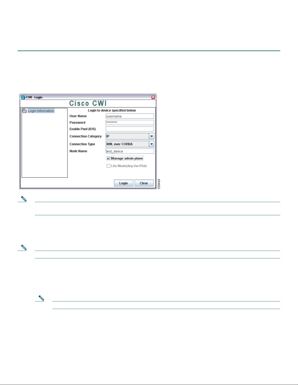
Step 1 Double-click the CWI icon to launch the client desktop. The CWI - Login window appears (see Figure 1).
You have the option to add a device or device group and log in to multiple routers. See the “Launching CWI from the
Device Tree” section on page 10 for more information.
Figure 1 CWI - Login Window
Note Enter the same AAA username and password that you used in Step 4 to access the router that must be configured. See the
“Installing CWI” section on page 7.
Step 2 Enter the same AAA username.
Step 3 Enter the same AAA password.
Step 4 (Optional) Enter the enable password for IOS.
Note When you connect to an IOS device, you must enter the enable password.
Step 5 Choose one of the following connection categories from the drop-down menu:
• IP
• Console/Aux
• Scripted
Note If you choose the IP-based or Console/Aux connection categories, the scripted login fields are not displayed.
Step 6 Choose one of the following connection types from the drop-down menu:
• XML over CORBA. Choose the node name. Note that XML over CORBA is the default.
• CLI over Telnet/SSH. Choose the server name. Specifying the port is optional. If you specify a port, CWI tries to
connect using only that port. CWI does not automatically try to connect with other ports.
• Terminal Server. Choose the server name and port.
• Serial Port. Choose the Serial Port. You can also set the parameters for the serial port.
9
Page 10

Step 7 (Optional) If you chose the Scripted connection category to log in to the intermediate or Scripted server:
a. Enter the Scripted username.
b. Enter the Scripted password.
c. Click the ellipsis button to display the Login Script Steps window (see Figure 7). Follow the procedure in the “Specifying
the User Login Script” section on page 15.
Note In addition, you must enter the applicable information in the Device Description field to uniquely identify the
connection. For example, if you are connecting to a device such as router_1 through the intermediate machine, enter
router_1 in the Description field.
Step 8 Enter the node name (DNS name or IP address) of the device that CWI is directly connecting to.
Step 9 (Optional) Check the Manage admin plane check box to enable the admin plane for the applicable device group or
device. If checked, the admin plane node appears above the corresponding device node in the Inventory Tree. For more
information, see “Understanding the Admin Planes and Device Planes” section on page 18.
Step 10 Click Login. Note that if you checked the Lite Mode check box, the XML option is disabled.
For SSL enabled: If you did not choose Always to automatically accept the SSL certificate from the “Installing CWI”
section on page 7, you must accept the SSL certificate.
Step 11 After the CWI initialization is completed, the CWI Desktop window appears. The chosen login mode is indicated in the
Inventory Tree. See the “CWI Desktop Window” section on page 19 for information on the CWI Desktop window.
Note CWI is automatically locked when there is no activity in the CWI session for 15 minutes. To unlock CWI, you
must provide the username and password used when logging in to the router. See Cisco Craft Works Interface
User Guide for CWI unlocking procedures.
If any of the minimum requirements of the initialization steps fails, a CWI dialog box appears allowing you to abort,
troubleshoot, or continue the initialization process.
Step 12 If necessary, complete the following steps to troubleshoot the initialization process.
a. To stop the initialization process, click Abort.
b. To troubleshoot the process, click Troubleshoot. The Troubleshooter application is started, and a Troubleshoot New
Device Launch problems dialog box appears. The Troubleshooter application runs fault isolation tests on the
client/server communication path between the CWI and router management agent. The Troubleshooter application
provides a window that describes the reason for the failure, possible cause, and recommended repair action. An
automatic repair option is provided in many instances. See Cisco
using the Troubleshooter feature.
c. To continue the initialization process, click Continue.
Craft Works Interface User Guide for information on
Launching CWI from the Device Tree
These sections describe how to launch CWI through configured devices or device groups:
• Adding or Editing a Device, page 11
• Adding or Editing a Device Group, page 12
• Removing a Device or Device Group, page 12
• Logging In to Multiple Network Elements, page 12
10
Page 11

Adding or Editing a Device
To add or edit a new device to the Device Tree, perform the following steps:
Step 1 From the CWI - Login window, right-click the Login information directory and choose Add New Device. The Add
Device window appears (see Figure 2). Or you can right-click the device in the Login information directory and choose
Edit to display the Edit Device window.
Figure 2 Add Device Window
Step 2 Choose one of the following connection categories from the drop-down menu:
• IP
• Console/Aux
• Scripted
Note If you choose the IP-based or Console/Aux connection categories, the scripted login fields are not displayed.
Step 3 Choose the applicable connection type from the drop-down list. For a list of the connections, see the “Launching CWI
Without Using the Device Tree” section on page 9.
Step 4 Click the ellipsis button to display the Login Script Steps window (see Figure 7). For more information on how to specify the
login script steps, see “Specifying the User Login Script” section on page 15.
Note This step is mandatory only if you selected the Scripted connection category.
Step 5 Enter the IP address or name of the node in the Node Name/Port field.
Step 6 (Optional) From the Device Tree, check the Manage admin plane check box to enable the admin plane for the applicable
device group or device. If checked, the admin plane node appears above the corresponding device node in the Inventory
Tree. For more information, see “Understanding the Admin Planes and Device Planes” section on page 18.
Step 7 (Optional) Check the Lite Mode check box to force a connection to the device in Lite Mode.
Step 8 Click OK to accept the device information for the Device Tree.
11
Page 12
Adding or Editing a Device Group
To add or edit a new device group to the device tree, perform the following steps:
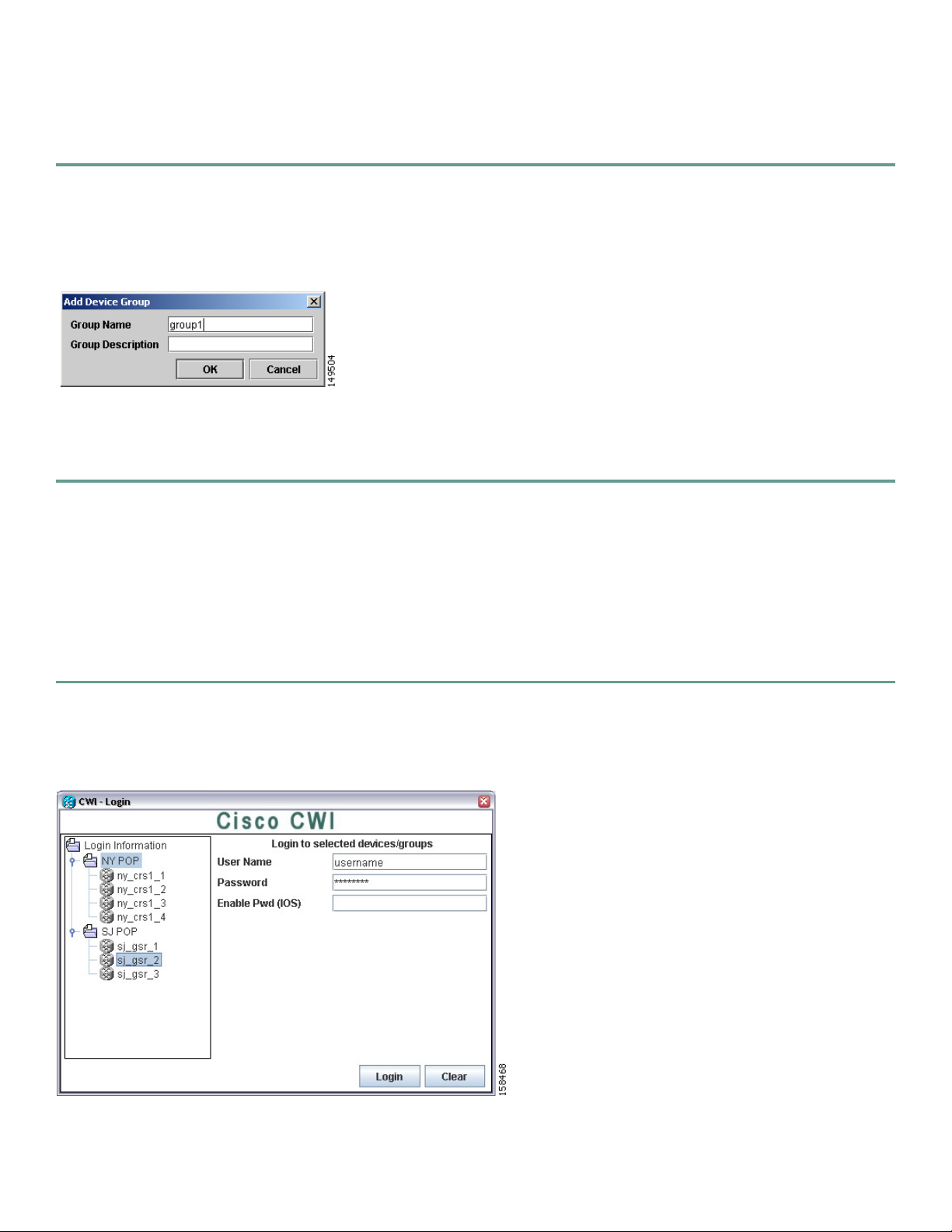
Step 1 From the CWI - Login window, right-click the Login Information directory and choose Add New Device Group. The
Add Device Group window appears (see Figure 3). Or you can right-click the device group and choose Edit to display
the Edit Device Group window.
Figure 3 Add Device Group Window
Step 2 Enter the name of the group in the Group Name field.
Step 3 (Optional) Enter a description of the group in the Group Description field.
Step 4 Click OK to accept the device group information for the device tree.
Removing a Device or Device Group
To remove a device or device group from the Login Information directory, right-click the device or device group and choose
Delete. Click Yes to confirm.
Logging In to Multiple Network Elements
To log in to multiple network elements, perform the following steps:
Step 1 From the CWI - Login window, choose the devices or device groups that you want to log in to. The CWI - Login for
Selected Devices/Groups window is displayed (see Figure 4).
Figure 4 CWI - Login for Selected Devices and Groups Window
Step 2 Enter the same AAA username across all routers.
12
Page 13

Step 3 Enter the same AAA password across all routers.
Step 4 (Optional) Enter the enable password for IOS.
Note When you connect to an IOS device, you must enter the enable password.
Step 5 Choose one of the following connection categories from the drop-down menu:
• IP
• Console/Aux
• Scripted
Note If you choose the IP-based or Console/Aux connection categories, the scripted login fields are not displayed.
Step 6 Choose one of the following connection types from the drop-down menu:
• XML over CORBA. Choose the node name. Note that XML over CORBA is the default.
• CLI over Telnet/SSH. Choose the server name. Specifying the port is optional. If you specify a port, CWI tries to
connect using only that port. CWI does not automatically try to connect with other ports.
• Terminal Server. Choose the server name and port.
• Serial Port. Choose the Serial Port. You can also set the parameters for the serial port.
Step 7 (Optional) If you chose the Scripted connection category to log in to the intermediate or Scripted server:
a. Enter the Scripted username.
b. Enter the Scripted password.
c. Click the ellipsis button to display the Login Script Steps window (see Figure 7). Follow the procedure in the “Specifying
the User Login Script” section on page 15.
Note In addition, you must enter the applicable information in the Device Description field to uniquely identify the
connection. For example, if you are connecting to a device such as router_1 through the intermediate machine, enter
router_1 in the Description field.
Step 8 Enter the node name (DNS name or IP address) of the device that CWI is directly connecting to.
Step 9 (Optional) From the device tree, check the Manage admin plane check box to enable the admin plane for the applicable
device group or device. If checked, the admin plane node appears above the corresponding device node in the Inventory
Tree. For more information, see “Understanding the Admin Planes and Device Planes” section on page 18.
Step 10 (Optional) Check the Lite Mode check box to force a connection to the device in Lite Mode.
Step 11 Click Login. You can log in to all devices simultaneously or one device. All devices appear in the Inventory Tree in the
same order as they are displayed in the Login Information directory.
Note If you are logged in to one device, the Inventory Tree is collapsed when the CWI Desktop appears. To expand the
Inventory Tree, click the right-arrow to display the objects in the Inventory Tree.
The progress window (see Figure 5) displays the login activity for each device. When the login has been completed for
all the devices, the main desktop appears.
13
Page 14

Figure 5 Progress Window
If one or more devices failed, see the “Encountering an Error While Logging into Multiple Devices Simultaneously”
section on page 14.
Encountering an Error While Logging into Multiple Devices Simultaneously
If an error is encountered while logging in to multiple devices simultaneously from the Progress window (see Figure 5), you can:
• Click the Continue to Desktop button if at least one device passed.
• Click the Back to Login button to go back to the CWI - Login window.
• Click the Details button that is located next to the failed device to display the entire log and display fallback and
troubleshooting options, if any.
14
Page 15

Figure 6 displays the Failed Log window. Click the Close button to go back to the Progress window.
Figure 6 Failed Log Window
Specifying the User Login Script
You can access devices not directly accessible from the CWI workstation through the Scripted Login capability. Table 5 lists the
fields in the Login Script Steps window (see Figure 7).
Table 5 Fields for Login Script Steps Window
Field Description
Wait For Represents the output from the intermediate device that CWI should wait for before sending the data specified
in the corresponding Send.
Send Represents the information that is sent to the device following the proceeding Wait For. You can enter a string
to be sent to connect to the router; for example, telnet term-server 2001. Or you can choose either Scripted
Username or Scripted Password options from the drop-down list. If you choose either Scripted Username
option or Scripted Password option, CWI uses the same scripted username and scripted password that you
specified from the CWI - Login window (see Figure 1).
In addition, you can enter the following special characters in the Send field:
• \n is a new line.
• \r is a carriage return.
• \t is a tab.
• %USERNAME%
1. CWI substitutes with what was entered in the User Name field when you logged in.
1
15
Page 16

Figure 7 Login Script Steps Window
The exact inputs depend on the intermediate server that is being used. If you are connecting to the intermediate machine by
using SSHv1 or SSHv2, you do not need to specify steps for sending the username and password to the intermediate machine,
because this is done when establishing a connection.
Table 6 lists the steps that you can enter for a Telnet connection to the intermediate server with a Telnet connection from the
server to the device.
Ta b le 6 Te l ne t E xa mp l e
Wait For Send
login Scripted Username
Password Scripted Password
<router prompt> telnet <router IP address>
Table 7 lists the steps that you can enter for a SSH connection.
Table 7 SSH Example
Wait For Send
login Scripted Username
Password Scripted Password
<router prompt> ssh -1 %USERNAME% <router IP address>
Depending on where you launched the Login Script Steps window, click OK to go back to the CWI - Login window or the Add
Device window.
Closing CWI
To close CWI, perform the following steps:
Step 1 Choose File> Exit. Or click the Close button on the CWI Desktop title bar.
A Craft Works Interface dialog box appears.
Step 2 Click Yes to exit the application.
The CWI Desktop window closes.
16
Page 17

Uninstalling CWI
To uninstall a specific version of CWI, perform the following steps:
Step 1 Navigate to the following CWI uninstall directory:
<CWI installation directory>/uninstall
Step 2 Execute the uninstall script of the desired version, as shown in the following example:
CWI_<version>_uninstall.cmd
For Windows, you have the option to double-click the CWI_<version>_uninstall.cmd filename to uninstall CWI. Follow
the online instructions.
6 Getting Started with the Operation of CWI
These sections describe how to get started with the operation of CWI:
• Installing and Accessing Online Help, page 17
• Understanding the Admin Planes and Device Planes, page 18
• Configuring a Router with CWI, page 18
• Capabilities of the CWI Desktop, page 18
• CWI Desktop Window, page 19
• Reference Information, page 21
When starting CWI, you can log into one or more devices or device groups. For more information, see the Logging In to Multiple
Network Elements, page 12.
Installing and Accessing Online Help
The first time the CWI Desktop is opened, the online help should be installed. The online help provides a descriptive overview
of the windows, menu items, toolbar buttons, status icons, and other interface features of CWI that can be launched from the
CWI Desktop Help menu. For information on the CWI Desktop Help menu, see Cisco Craft Works Interface User Guide.
To install the CWI online help, perform the following steps:
Step 1 In the CWI Desktop, choose Help > Help Desktop.
A Help dialog box appears.
Step 2 Click Yes to install help.
An Online Help Installer dialog box appears and downloads the help files. When the download is complete, a CWI Help
installation complete message appears in the dialog box.
Step 3 Click Close.
The Online Help Installer dialog box closes.
Step 4 To access the online help, choose Help > Help Desktop to open the online help.
17
Page 18

Understanding the Admin Planes and Device Planes
For Cisco IOS XR devices, CWI can manage both the admin planes and device planes on a single desktop. A node is available
for each plane in the Inventory Tree of the CWI desktop. Each plane provides you with different domains (see Table 8).
Table 8 Supported Domains
Node Application Inventory
Device All
Admin Inventory Viewer Nonshared and shared. For example, power supplies, fans, fabric,
1. You cannot access the Rack Environment Monitor application from the device node.
2. PLIM = physical layer interface module
3. SPA = shared port adapter
1
Rack Environment Monitor
Card Environment Monitor
Sensor Environment Monitor
Telnet
SSHv1
SSHv2
Configuration Editor
Nonshared. For example, line cards, PLIMs2, SPAs3, and so forth.
and so forth.
Configuring a Router with CWI
Table 9 lists the applications to configure a router using CWI.
Table 9 Applications Used to Configure a Router with CWI
Application Function
Telnet/SSH/Terminal Plus Configures and manages the router using CLI commands.
Configuration Editor Views and edits the running configuration in CLI format. The configuration editor provides
common text editing functionality, such as copying, pasting, redoing, and undoing, and
provides syntax checking. In addition, you can use traditional CLI features and functions, such
as command completion and CLI help.
Capabilities of the CWI Desktop
The following capabilities of the CWI Desktop are described:
• View, filter, sort, search, correlate, purge, and monitor real-time alarms.
• View, filter, export, and search real-time inventory and interface object attribute information.
• Monitor network elements to display various attributes of the state of one or more devices, such as environmental and
performance data.
• Troubleshoot management connectivity problems.
• View and modify a configuration through the Configuration Editor.
• Use Telnet or Secure Shell (SSH) for command-line interaction with the router.
• Display a dynamic graphical representations of routers.
• Print, export, and search data.
• Sort and move columns.
18
Page 19

• Filter records.
• Set preferences.
CWI Desktop Window
The CWI Desktop is the main point of access to all CWI applications and tools, allowing you to configure, monitor, and manage
routers (see Figure 8).
The CWI Desktop is designed with common elements that provide an easy-to-use and consistent user interface. The elements of
the CWI Desktop window are described in Table 10.
Table 10 CWI Desktop Window Elements
Element Description
Menu bar Provides a list of options available on the basis of the selected object and active application. The
options include administrating tasks, editing tasks, viewing tasks, starting applications, and arranging
windows.
Toolbar Contains icons, referred to as tools, that provide direct access to context-sensitive functions. Clicking
a tool selects a task.
Inventory Tree Displays all components of each router that CWI can access and is the primary interface to these
components. The Inventory Tree dynamically shows current alarms and events, connectivity status,
and physical and logical tree views. The Inventory Tree provides context-sensitive launching of
applications by selecting an object, a group of objects, or an entire router in the Inventory Tree and
then choosing an available application
CWI application pane Contains the active CWI applications that are used to manage the router. Multiple applications can
be opened concurrently in the CWI application pane.
19
Page 20

Figure 8 CWI Desktop
Inventory tree
1
CWI Desktop menu bar
2
The CWI Desktop lets you to communicate with the router using the applications that are described in Table 11.
Table 11 Applications for the CWI Desktop
CWI Desktop toolbar
3
CWI application pane
4
Application Description
Alarm Dashboard Provides a summary of the alarm status information for all routers on the CWI Desktop. A
color code is used to indicate active alarm counts by severity. A resettable running count of
new alarm arrivals is provided.
Alarm Viewer Provides an interface between CWI and the alarm management functions of the router
controller, allowing you to dynamically view alarm records with powerful filtering
capabilities. Alarm Viewer also provides a launch point to view correlated alarms.
Inventory Viewer Displays the attribute values of selected objects.
Interface Viewer Provides a view of interface attributes for selected cards.
Telnet/SSH/Terminal Plus Provides the capability to issue CLI commands and view session information within CWI.
Telnet/SSH/Terminal Plus includes additional CWI features for creating command lists and
running commands from the command list, saving and loading command lists from a file, and
running in batch mode. Additionally, console text can be displayed in a separate window. The
SSH application connects to the router with a secure connection.
Troubleshooter Provides fault isolation and repair of connectivity problems between CWI and router.
20
Page 21

Table 11 Applications for the CWI Desktop (continued)
Application Description
Configuration Editor Displays the target configuration in CLI format. The Configuration Editor provides general
text editor functions, such as copy, paste, redo, and undo, and provides syntax checking and
CLI functions, such as command completion and CLI help.
Fabric Status Viewer Displays the port ID and port status columns in text format in a Fabric Status Viewer table.
Rack Environment Monitor Displays the attributes at the rack level.
Card Environment Monitor Displays the attributes at the card level.
Sensor Environment Monitor Displays the attributes at the sensor level.
Health Monitor Displays the attributes for each card.
Performance System Monitor Displays the system-wide performance statistics.
Performance Process Monitor Displays the attributes for each process.
Performance Interface
Monitor
Displays the attributes at the interface level.
7 Reference Information
These sections describe additional reference information:
• Network Considerations, page 21
• Login Modes and Requirements, page 22
• CWI Supported Connection Methods and Applications, page 23
• Testing the CWI Client, page 24
Network Considerations
Before you start setting up the minimum router and CWI client configurations, network information must be taken into
consideration (see Table 12). Note that the specific setup is dependent on the session used from the “About CWI” section.
Table 12 Network Information
Type Function
Network Security The default configuration is not secure.
SSL Encryption Configuration The secure configuration uses Secure Socket Layer (SSL) encryption. If you use the SSL
protocol on your network, use the SSL configuration.
IP Security IP security (IPSec) does not require any special configuration for CWI on the router or client.
Firewall If you have a firewall in your network, you can use the basic or SSL encryption configuration.
See Table 13 for a list of firewall ports.
21
Page 22

Table 12 Network Information (continued)
Type Function
VPN When setting the minimum router configuration, you must use the client Virtual Private
Network (VPN) IP address and Domain Name Server (DNS) name instead of the client IP
address and DNS name when configuring the IP hostname for the CWI client. This mapping
is required for the client to receive notifications from the router.
If you have a VPN, you can use the basic or SSL encryption configuration.
Dual-Homed Dual-homed devices are used to bridge two networks. You can run an instance of CWI on the
dual-homed device so that you can access the secondary network. You need terminal services
or X-client software to run the CWI graphical application from the client PC. A dual-homed
device contains a client-side interface (IP address) and router-side interface (IP address).
If you have a dual-homed device in your network, you can use the standard or SSL encryption
configuration. See Figure 9 for an example.
You must open the ports listed in Table 13 when configuring the firewall. See the firewall documentation for information on
opening the ports.
Table 13 Firewall Ports
Component Port Direction
HTTP and HTTPS 80/443 Inbound
CORBA and CORBA SSL 10001/10002 Inbound
CORBA Notifications 49901 to 49950 Outbound
Telnet and SSH 23/22 Inbound and Outbound
For an example of a dual-homed device configuration, the client side is the primary interface, and the router side is the secondary
interface (see Figure 9). When setting the minimum router configuration, you must use the dual-homed device router side
(secondary) IP address and DNS name when configuring the IP hostname for the CWI client. This mapping is required for the
client to view the notifications from the router received by the dual-homed instance of CWI.
Figure 9 Dual-Homed Device Configuration
S
E
C
O
N
D
A
R
Y
Router
111615
Client PC
P
R
I
M
A
R
Y
Dual-homed device
Login Modes and Requirements
A primary goal of CWI is to communicate with a device in any state by dynamically supporting three operational modes (see
Table 14). CWI can manage multiple devices with different modes simultaneously.
The three different login modes are based on the following requirements:
• Connection methods
• MGBL-PIE files (installed or not installed). MGBL refers to Manageability. PIE refers to Package Installation Envelope.
22
Page 23

• HTTP server status (running or not running)
• XML agent status (running or not running)
Table 14 lists the applications and features to the corresponding login mode type.
Table 14 Login Modes Used for Applications and Features
Mode Description
Full Mode (MGBL-PIE and XML Agent) The entire set of CWI applications is provided. The following list of features is
included:
• Reduced Mode of applications and features
• Notification-driven features
• Troubleshooter application
• Rack Environment Monitor
• Card Environment Monitor
• Sensor Environment Monitor
• Health Monitor
• Performance System Monitor
• Performance Process Monitor
• Performance Interface Monitor
Reduced Mode Reduced Mode functions as a default that operates independently of the presence
of the manageability pie or state of XML agent. The following CWI applications
are included:
• Lite Mode of applications and features
• Inventory Tree
• Inventory Viewer application
• Interface Viewer application
• Alarm Viewer application
• Health Monitor
CWI Lite Mode CWI communicates with the device using CLI and not XML
operates under any circumstances and always works. This mode has no
dependence on chassis type, software version, presence of the manageability pie,
or state of the XML agent. The following features are included:
• CWI Desktop
• Telnet, Terminal Plus, and SSH
• Configuration Editor application
1. XML = Extensible Markup Language
1
. CWI Lite Mode
CWI Supported Connection Methods and Applications
Table 15 provides detailed information on the supported CWI connection methods and available applications.
Note If you are connecting to the router through either the Terminal Server or Serial Port connection methods from CWI,
you must ensure that the logging console is not configured on the router.
23
Page 24

Table 15 Connection Methods and Applications
Console Port (Serial Cable or
CWI Application
Launch and Login Yes. Enter the serial port or
Main Desktop Yes, but no notifications or
Alarm Viewer Yes, but no alerts are
Alarm Dashboard — — Yes
Inventory Viewer Yes Yes Yes
Interface Viewer Yes Yes Yes
Telnet Plus/SSH Plus — Yes Yes
Terminal Plus Yes, but are mutually exclusive
Troubleshooter — — Yes
Configuration Editor Yes Yes Yes
1. When connecting through the serial port or terminal server, the Terminal Plus application requires exclusive access to the connection, so no
other applications can be launched or refreshed while it is open.
Through a Terminal Server) Telnet (No XML)
Yes. Enter the DNS name or IP
terminal server and port name.
associated alarms are
displayed.
displayed.
1
other applications
.
address.
Yes, but no notifications or
associated alarms are
displayed.
Yes, but no alerts are
displayed.
——
Telnet/SSH, or CORBA
Connection (XML)
Yes. Enter the DNS name or IP
address.
Yes
Yes
Testing the CWI Client
Verify that you can connect to the router by logging in to the router. See the “Installing CWI” section on page 7 for procedures.
If you are unable to log in to the router, see the “Troubleshooting Basic IP Connectivity” section on page 24.
Troubleshooting Basic IP Connectivity
This section provides information on troubleshooting basic IP connectivity problems when attempting to log in to a router using
CWI.
If you are unable to connect to the router HTTP server using the browser, follow these steps in sequence, exiting the test steps
when a failure is encountered.
Step 1 Ping the IP address of the router management Ethernet interface from the client PC or workstation.
If this step fails, the problem can be an incorrect IP address, incorrect management Ethernet interface configuration, or
a network connectivity problem.
Step 2 (Optional) Ping the DNS name of the router.
If this step fails, the problem is an incorrect hostname-to-IP address mapping. See the “Configuring the Router and CWI
Client” section on page 4.
Step 3 Check that the HTTP server is running on the router using the following command:
RP/0/RP0/CPU0:router# show process emweb
If this step fails, start the HTTP server. See the “Setting Up the Common Configuration for IP Connection Methods”
section on page 5.
If you are unable to log in to the router from the CWI login screen, run the Troubleshooter application at the prompt. See Cisco
Craft Works Interface User Guide for information on using the Troubleshooter application.
24
Page 25

8 Obtaining Documentation
Cisco documentation and additional literature are available on Cisco.com. This section explains the product documentation
resources that Cisco offers.
Cisco.com
You can access the most current Cisco documentation at this URL:
http://www.cisco.com/techsupport
You can access the Cisco website at this URL:
http://www.cisco.com
You can access international Cisco websites at this URL:
http://www.cisco.com/public/countries_languages.shtml
Product Documentation DVD
The Product Documentation DVD is a library of technical product documentation on a portable medium. The DVD enables you
to access installation, configuration, and command guides for Cisco hardware and software products. With the DVD, you have
access to the HTML documentation and some of the PDF files found on the Cisco website at this URL:
http://www.cisco.com/univercd/home/home.htm
The Product Documentation DVD is created and released regularly. DVDs are available singly or by subscription. Registered
Cisco.com users can order a Product Documentation DVD (product number DOC-DOCDVD= or DOC-DOCDVD=SUB) from
Cisco Marketplace at the Product Documentation Store at this URL:
http://www.cisco.com/go/marketplace/docstore
Ordering Documentation
You must be a registered Cisco.com user to access Cisco Marketplace. Registered users may order Cisco documentation at the
Product Documentation Store at this URL:
http://www.cisco.com/go/marketplace/docstore
If you do not have a user ID or password, you can register at this URL:
http://tools.cisco.com/RPF/register/register.do
9 Documentation Feedback
You can provide feedback about Cisco technical documentation on the Cisco Technical Support & Documentation site area by
entering your comments in the feedback form available in every online document.
10 Cisco Product Security Overview
Cisco provides a free online Security Vulnerability Policy portal at this URL:
http://www.cisco.com/en/US/products/products_security_vulnerability_policy.html
From this site, you will find information about how to do the following:
• Report security vulnerabilities in Cisco products
• Obtain assistance with security incidents that involve Cisco products
• Register to receive security information from Cisco
25
Page 26

A current list of security advisories, security notices, and security responses for Cisco products is available at this URL:
http://www.cisco.com/go/psirt
To see security advisories, security notices, and security responses as they are updated in real time, you can subscribe to the
Product Security Incident Response Team Really Simple Syndication (PSIRT RSS) feed. Information about how to subscribe to
the PSIRT RSS feed is found at this URL:
http://www.cisco.com/en/US/products/products_psirt_rss_feed.html
Reporting Security Problems in Cisco Products
Cisco is committed to delivering secure products. We test our products internally before we release them, and we strive to correct
all vulnerabilities quickly. If you think that you have identified a vulnerability in a Cisco product, contact PSIRT:
• For emergencies only—security-alert@cisco.com
An emergency is either a condition in which a system is under active attack or a condition for which a severe and urgent
security vulnerability should be reported. All other conditions are considered nonemergencies.
• For nonemergencies— psirt@cisco.com
In an emergency, you can also reach PSIRT by telephone:
• 1 877 228-7302
• 1 408 525-6532
Tip We encourage you to use Pretty Good Privacy (PGP) or a compatible product (for example, GnuPG) to encrypt any
sensitive information that you send to Cisco. PSIRT can work with information that has been encrypted with PGP
versions 2.x through 9.x.
Never use a revoked encryption key or an expired encryption key. The correct public key to use in your correspondence
with PSIRT is the one linked in the Contact Summary section of the Security Vulnerability Policy page at this URL:
http://www.cisco.com/en/US/products/products_security_vulnerability_policy.html
The link on this page has the current PGP key ID in use.
If you do not have or use PGP, contact PSIRT to find other means of encrypting the data before sending any sensitive
material.
11 Product Alerts and Field Notices
Modifications to or updates about Cisco products are announced in Cisco Product Alerts and Cisco Field Notices. You can
receive Cisco Product Alerts and Cisco Field Notices by using the Product Alert Tool on Cisco.com. This tool enables you to
create a profile and choose those products for which you want to receive information.
To access the Product Alert Tool, you must be a registered Cisco.com user. (To register as a Cisco.com user, go to this URL:
http://tools.cisco.com/RPF/register/register.do) Registered users can access the tool at this URL:
http://tools.cisco.com/Support/PAT/do/ViewMyProfiles.do?local=en
12 Obtaining Technical Assistance
Cisco Technical Support provides 24-hour-a-day award-winning technical assistance. The Cisco Technical Support &
Documentation website on Cisco.com features extensive online support resources. In addition, if you have a valid Cisco service
contract, Cisco Technical Assistance Center (TAC) engineers provide telephone support. If you do not have a valid Cisco service
contract, contact your reseller.
26
Page 27

Cisco Technical Support & Documentation Website
The Cisco Technical Support & Documentation website provides online documents and tools for troubleshooting and resolving
technical issues with Cisco products and technologies. The website is available 24 hours a day at this URL:
http://www.cisco.com/techsupport
Access to all tools on the Cisco Technical Support & Documentation website requires a Cisco.com user ID and password. If you
have a valid service contract but do not have a user ID or password, you can register at this URL:
http://tools.cisco.com/RPF/register/register.do
Note Use the Cisco Product Identification Tool to locate your product serial number before submitting a request for service
online or by phone. You can access this tool from the Cisco Technical Support & Documentation website by clicking
the Tools & Resources link, clicking the All Tools (A-Z) tab, and then choosing Cisco Product Identification Tool from
the alphabetical list. This tool offers three search options: by product ID or model name; by tree view; or, for certain
products, by copying and pasting show command output. Search results show an illustration of your product with the
serial number label location highlighted. Locate the serial number label on your product and record the information
before placing a service call.
Tip Displaying and Searching on Cisco.com
If you suspect that the browser is not refreshing a web page, force the browser to update the web page by holding down
the Ctrl key while pressing F5.
To find technical information, narrow your search to look in technical documentation, not the entire Cisco.com
website. On the Cisco.com home page, click the Advanced Search link under the Search box and then click the Technical
Support & Documentation radio button.
To provide feedback about the Cisco.com website or a particular technical document, click Contacts & Feedback at the
top of any Cisco.com web page.
Submitting a Service Request
Using the online TAC Service Request Tool is the fastest way to open S3 and S4 service requests. (S3 and S4 service requests are
those in which your network is minimally impaired or for which you require product information.) After you describe your
situation, the TAC Service Request Tool provides recommended solutions. If your issue is not resolved using the recommended
resources, your service request is assigned to a Cisco engineer. The TAC Service Request Tool is located at this URL:
http://www.cisco.com/techsupport/servicerequest
For S1 or S2 service requests, or if you do not have Internet access, contact the Cisco TAC by telephone. (S1 or S2 service
requests are those in which your production network is down or severely degraded.) Cisco engineers are assigned immediately
to S1 and S2 service requests to help keep your business operations running smoothly.
To open a service request by telephone, use one of the following numbers:
Asia-Pacific: +61 2 8446 7411
Australia: 1 800 805 227
EMEA: +32 2 704 55 55
USA: 1 800 553 2447
For a complete list of Cisco TAC contacts, go to this URL:
http://www.cisco.com/techsupport/contacts
Definitions of Service Request Severity
To ensure that all service requests are reported in a standard format, Cisco has established severity definitions.
27
Page 28

Severity 1 (S1)—An existing network is “down” or there is a critical impact to your business operations. You and Cisco will
commit all necessary resources around the clock to resolve the situation.
Severity 2 (S2)—Operation of an existing network is severely degraded, or significant aspects of your business operations are
negatively affected by inadequate performance of Cisco products. You and Cisco will commit full-time resources during normal
business hours to resolve the situation.
Severity 3 (S3)—Operational performance of the network is impaired while most business operations remain functional. You
and Cisco will commit resources during normal business hours to restore service to satisfactory levels.
Severity 4 (S4)—You require information or assistance with Cisco product capabilities, installation, or configuration. There is
little or no effect on your business operations.
13 Obtaining Additional Publications and Information
Information about Cisco products, technologies, and network solutions is available from various online and printed sources.
• The Cisco Online Subscription Center is the website where you can sign up for a variety of Cisco e-mail newsletters and
other communications. Create a profile and then select the subscriptions that you would like to receive. To visit the Cisco
Online Subscription Center, go to this URL:
http://www.cisco.com/offer/subscribe
• The Cisco Product Quick Reference Guide is a handy, compact reference tool that includes brief product overviews, key
features, sample part numbers, and abbreviated technical specifications for many Cisco products that are sold through
channel partners. It is updated twice a year and includes the latest Cisco channel product offerings. To order and find out
more about the Cisco Product Quick Reference Guide, go to this URL:
http://www.cisco.com/go/guide
• Cisco Marketplace provides a variety of Cisco books, reference guides, documentation, and logo merchandise. Visit
Cisco Marketplace, the company store, at this URL:
http://www.cisco.com/go/marketplace/
• Cisco Press publishes a wide range of general networking, training, and certification titles. Both new and experienced users
will benefit from these publications. For current Cisco Press titles and other information, go to Cisco Press at this URL:
http://www.ciscopress.com
• Internet Protocol Journal is a quarterly journal published by Cisco Systems for engineering professionals involved in
designing, developing, and operating public and private internets and intranets. You can access the Internet Protocol
Journal at this URL:
http://www.cisco.com/ipj
• Networking products offered by Cisco Systems, as well as customer support services, can be obtained at this URL:
http://www.cisco.com/en/US/products/index.html
• Networking Professionals Connection is an interactive website where networking professionals share questions,
suggestions, and information about networking products and technologies with Cisco experts and other networking
professionals. Join a discussion at this URL:
http://www.cisco.com/discuss/networking
• “What’s New in Cisco Documentation” is an online publication that provides information about the latest documentation
releases for Cisco products. Updated monthly, this online publication is organized by product category to direct you quickly
to the documentation for your products. You can view the latest release of “What’s New in Cisco Documentation” at this
URL:
http://www.cisco.com/univercd/cc/td/doc/abtunicd/136957.htm
• World-class networking training is available from Cisco. You can view current offerings at this URL:
http://www.cisco.com/en/US/learning/index.html
28
Page 29

29
Page 30

30
Page 31

Corporate Headquarters
Cisco Systems, Inc.
170 West Tasman Drive
San Jose, CA 95134-1706
USA
www.cisco.com
Tel: 408 526-4000
800 553-NETS (6387)
Fax: 408 526-4100
European Headquarters
Cisco Systems International BV
Haarlerbergpark
Haarlerbergweg 13-19
1101 CH Amsterdam
The Netherlands
www-europe.cisco.com
Tel: 31 0 20 357 1000
Fax: 31 0 20 357 1100
Americas Headquarters
Cisco Systems, Inc.
170 West Tasman Drive
San Jose, CA 95134-1706
USA
www.cisco.com
Tel: 408 526-7660
Fax: 408 527-0883
Asia Pacific Headquarters
Cisco Systems, Inc.
168 Robinson Road
#28-01 Capital Tower
Singapore 068912
www.cisco.com
Tel: +65 6317 7777
Fax: +65 6317 7799
Cisco Systems has more than 200 offices in the following countries. Addresses, phone numbers, and fax numbers are listed on the
Cisco Web site at www.cisco.com/go/offices
Argentina • Australia • Austria • Belgium • Brazil • Bulgaria • Canada • Chile • China PRC • Colombia • Costa Rica • Croatia • Cyprus • Czech Republic • Denmark
Dubai, UAE • Finland • France • Germany • Greece • Hong Kong SAR • Hungary • India • Indonesia • Ireland • Israel • Italy • Japan • Korea • Luxembourg • Malaysia
Mexico • The Netherlands • New Zealand • Norway • Peru • Philippines • Poland • Portugal • Puerto Rico • Romania • Russia • Saudi Arabia • Scotland • Singapore
Slovakia • Slovenia • South Africa • Spain • Sweden • Switzerland • Taiwan • Thailand • Turkey • Ukraine • United Kingdom • United States • Venezuela • Vietnam
Zimbabwe
CVP, the Cisco logo, and the Cisco Square Bridge logo are trademarks of Cisco Systems, Inc.; Changing the Way We Work, Live, Play, and Learn is a service mark of Cisco Systems, Inc.; and Access Registrar,
ironet, BPX, Catalyst, CCDA, CCDP, CCIE, CCIP, CCNA, CCNP, CCSP, Cisco, the Cisco Certified Internetwork Expert logo, Cisco IOS, Cisco Press, Cisco Systems, Cisco Systems Capital, the Cisco Systems logo,
isco Unity, Enterprise/Solver, EtherChannel, EtherFast, EtherSwitch, Fast Step, Follow Me Browsing, FormShare, GigaDrive, HomeLink, Internet Quotient, IOS, iPhone, IP/TV, iQ Expertise, the iQ logo, iQ Net
eadiness Scorecard, iQuick Study, LightStream, Linksys, MeetingPlace, MGX, Networking Academy, Network Registrar, PIX, ProConnect, ScriptShare, SMARTnet, StackWise, The Fastest Way to Increase Your
nternet Quotient, and TransPath are registered trademarks of Cisco Systems, Inc. and/or its affiliates in the United States and certain other countries.
ll other trademarks mentioned in this document or Website are the property of their respective owners. The use of the word partner does not imply a partnership relationship between Cisco and any other company.
0709R)
© 2006 Cisco Systems, Inc. All rights reserved.
Printed in the USA on recycled paper containing 10% postconsumer waste.
OL-11308-01
Page 32

32
 Loading...