

Page 1

Cisco CSS UCS Platform Series User Guide, CPS-UCS-1RU-K9 / CPS-UCS-2RU-K9
Revised: April, 2016
Document release 1.1
Americas Headquarters
Cisco Systems, Inc.
170 West Tasman Drive
San Jose, CA 95134-1706
USA
http://www.cisco.com
Tel: 408 526-4000
800 553-NETS (6387)
Fax: 408 527-0883
Page 2

THE SPECIFICATIONS AND INFORMATION REGARDING THE PRODUCTS IN THIS MANUAL ARE SUBJECT TO CHANGE WITHOUT NOTICE. ALL
STATEMENTS, INFORMATION, AND RECOMMENDATIONS IN THIS MANUAL ARE BELIEVED TO BE ACCURATE BUT ARE PRESENTED WITHOUT
WARRANTY OF ANY KIND, EXPRESS OR IMPLIED. USERS MUST TAKE FULL RESPONSIBILITY FOR THEIR APPLICATION OF ANY PRODUCTS.
THE SOFTWARE LICENSE AND LIMITED WARRANTY FOR THE ACCOMPANYING PRODUCT ARE SET FORTH IN THE INFORMATION PACKET THAT
SHIPPED WITH THE PRODUCT AND ARE INCORPORATED HEREIN BY THIS REFERENCE. IF YOU ARE UNABLE TO LOCATE THE SOFTWARE LICENSE
OR LIMITED WARRANTY, CONTACT YOUR CISCO REPRESENTATIVE FOR A COPY.
The Cisco implementation of TCP header compression is an adaptation of a program developed by the University of California, Berkeley (UCB) as part of UCB’s public
domain version of the UNIX operating system. All rights reserved. Copyright © 1981, Regents of the University of California.
NOTWITHSTANDING ANY OTHER WARRANTY HEREIN, ALL DOCUMENT FILES AND SOFTWARE OF THESE SUPPLIERS ARE PROVIDED “AS IS” WITH
ALL FAULTS. CISCO AND THE ABOVE-NAMED SUPPLIERS DISCLAIM ALL WARRANTIES, EXPRESSED OR
LIMITATION, THOSE OF MERCHANTABILITY, FITNESS FOR A PARTICULAR PURPOSE AND NONINFRINGEMENT OR ARISING FROM A COURSE OF
DEALING, USAGE, OR TRADE PRACTICE.
IN NO EVENT SHALL CISCO OR ITS SUPPLIERS BE LIABLE FOR ANY INDIRECT, SPECIAL, CONSEQUENTIAL, OR INCIDENTAL DAMAGES, INCLUDING,
WITHOUT LIMITATION, LOST PROFITS OR LOSS OR DAMAGE TO DATA ARISING OUT OF THE USE OR INABILITY TO USE THIS MANUAL, EVEN IF CISCO
OR ITS SUPPLIERS HAVE BEEN ADVISED OF THE POSSIBILITY OF SUCH DAMAGES.
Cisco and the Cisco logo are trademarks or registered trademarks of Cisco and/or its affiliates in the U.S. and other countries. To view a list of Cisco trademarks, go to this
URL:
www.cisco.com/go/trademarks. Third-party trademarks mentioned are the property of their respective owners. The use of the word partner does not imply a partnership
relationship between Cisco and any other company. (1110R)
Any Internet Protocol (IP) addresses and phone numbers used in this document are not intended to be actual addresses and phone numbers. Any examples, command display
output, network topology diagrams, and other figures included in the document are shown for illustrative purposes only. Any use of actual IP addresses or phone numbers in
illustrative content is unintentional and coincidental.
Cisco CSS UCS Platform Series User Guide, CPS-UCS-1RU-K9 / CPS-UCS-2RU-K9
© 2013 - 2016 Cisco Systems, Inc. All rights reserved.
IMPLIED, INCLUDING, WITHOUT
Page 3

CONTENTS
Preface v
Purpose v
Revision History v
Related Documentation v
Obtaining Documentation, Obtaining Support, and Security Guidelines vi
Command Syntax Conventions vi
CHAPTER
1 Overview 1-1
System Overview 1-2
Server Model Comparison 1-2
Cisco Connected Safety and Security UCS C220 (1RU) Overview 1-2
Cisco Connected Safety and Security UCS C240 (2RU) Overview 1-6
Status LEDs and Buttons 1-10
Cisco Connected Safety and Security UCS C220 LEDs and Buttons 1-10
Cisco Connected Safety and Security UCS C240 LEDs and Buttons 1-15
Cisco Connected Safety and Security UCS C220 Front Panel 1-3
Cisco Connected Safety and Security UCS C220 Rear Panel 1-4
Summary of Cisco Connected Safety and Security UCS C220 Server Features 1-4
Cisco Connected Safety and Security UCS C240 Front Panel 1-6
Cisco Connected Safety and Security UCS C240 Rear Panel 1-7
Summary of Cisco Connected Safety and Security UCS C240 Server Features 1-8
Front Panel LEDs 1-10
Rear Panel LEDs and Buttons 1-12
Internal Diagnostic LEDs 1-14
Front Panel LEDs 1-15
Rear Panel LEDs and Buttons 1-17
Internal Diagnostic LEDs 1-18
Supported PSBU Hardware Configurations 1-20
DIMM Memory Configuration 1-20
Cisco Connected Safety and Security UCS C220 Memory 1-20
Cisco Connected Safety and Security UCS C240 Memory 1-20
Supported NIC (GigE) Ports (Cisco Video Surveillance) 1-21
Server and Accessories Part Numbers 1-22
Server Monitoring and Management Tools 1-22
Cisco CSS UCS Platform Series User Guide, CPS-UCS-1RU-K9 / CPS-UCS-2RU-K9
i
Page 4

Contents
Cisco Integrated Management Interface (CIMC) 1-22
Cisco Video Surveillance Management Console 1-22
Supported Applications 1-23
CHAPTER
CHAPTER
2 Supported Applications 2-1
Cisco Video Surveillance Manager, Release 7.2 and Higher 2-1
Overview 2-1
Initial Setup Procedure 2-2
Upgrading the Cisco VSM System Software 2-2
Recovering the Cisco VSM System Software 2-2
Supported RAID and Hard Drive Configurations (Cisco VSM) 2-3
Requirements and Conditions 2-4
Supported RAID Upgrade Paths 2-4
Supported Hard Drives 2-5
Requirements for All Servers 2-5
Cisco Connected Safety and Security UCS C220 Hard Disk Configuration 2-5
Cisco Connected Safety and Security UCS C240 Hard Disk Configuration 2-5
More Information 2-6
3 Installing the Server 3-1
Unpacking and Inspecting the Server 3-2
Preparing for Server Installation 3-3
Installation Guidelines 3-3
Rack Requirements 3-4
Equipment Requirements 3-4
Slide Rail Adjustment Range 3-4
Installing the Cisco Connected Safety and Security UCS C220 Server In a Rack 3-5
Installing the Cisco Connected Safety and Security UCS C240 Server In a Rack 3-9
Installing the Slide Rails 3-9
Installing the Cable Management Arm (Optional) 3-12
Reversing the Cable Management Arm (Optional) 3-14
Initial Server Setup 3-16
Connecting and Powering On the Server (Standalone Mode) 3-16
System BIOS and CIMC Firmware 3-18
Updating the BIOS and CIMC Firmware 3-18
Accessing the System BIOS 3-19
Cisco CSS UCS Platform Series User Guide, CPS-UCS-1RU-K9 / CPS-UCS-2RU-K9
ii
Page 5

Contents
CHAPTER
4 Replacing Hardware Components 4-1
Preparing for Server Component Installation 4-1
Required Equipment 4-2
Shutting Down and Powering Off the Server 4-2
Removing and Replacing the Server Top Cover 4-3
Cisco Connected Safety and Security UCS C220 Top Cover 4-3
Cisco Connected Safety and Security UCS C240 Top Cover 4-4
Replaceable Component Locations 4-6
Cisco Connected Safety and Security UCS C220 Replaceable Components 4-6
Cisco Connected Safety and Security UCS C240 Replaceable Components 4-7
Serial Number Location 4-9
Color-Coded Touch Points 4-9
Installing or Replacing Server Components 4-9
Replacing Hard Drives 4-9
Cisco Connected Safety and Security UCS C220: Replacing a Hard Drive 4-9
Cisco Connected Safety and Security UCS C240: Replacing a Hard Drive 4-11
Replacing a PCIe Card 4-13
Emulex LPe 12002 Dual Port 8Gb Fibre Channel HBA Card 4-13
Installing or Replacing a PCIe Card: Cisco Connected Safety and Security UCS C220 4-13
Installing or Replacing a PCIe Card: Cisco Connected Safety and Security UCS C240 4-15
Replacing Additional Hardware Components (Related Documentation) 4-18
APPENDIX
APPENDIX
A Server Specifications A-1
Cisco Connected Safety and Security UCS C220 (1RU) Specifications A-1
Physical Specifications A-1
Environmental Specifications A-2
Power Specifications A-2
Cisco Connected Safety and Security UCS C240 (2RU) Specifications A-3
Physical Specifications A-3
Environmental Specifications A-3
Power Specifications A-4
B Related Documentation B-1
Cisco CSS UCS Platform Series User Guide, CPS-UCS-1RU-K9 / CPS-UCS-2RU-K9
iii
Page 6

Contents
iv
Cisco CSS UCS Platform Series User Guide, CPS-UCS-1RU-K9 / CPS-UCS-2RU-K9
Page 7

Purpose
Preface
This document summarizes the requirements and supported features of the following Cisco Connected
Safety and Security UCS Platform Series servers:
• CPS-UCS-1RU-K9
• CPS-UCS-2RU-K9
This document also includes a summary of common installation and configuration topics, and links to
tailed instructions. Additional summaries are included for the applications supported on the servers,
de
such as the Cisco Video Surveillance Manager.
Revision History
Ta b l e 1 Revision History
Document
Release
Release 1.0 September, 2013 Initial draft
Release 1.0 September, 2015 Updated for Cisco VSM Release 7.7
Release 1.1 April, 2016 Updated to clarify that this document is for the following servers only:
Document
Revision Date Change Summary
• CPS-UCS-1RU-K9
• CPS-UCS-2RU-K9
Related Documentation
This document describes installation of the following Cisco Connected Safety and Security servers:
• CPS-UCS-1RU-K9
• CPS-UCS-2RU-K9
Cisco CSS UCS Platform Series User Guide, CPS-UCS-1RU-K9 / CPS-UCS-2RU-K9
v
Page 8
Note For information about the CPS-UCSM4-1RU-K9 and CPS-UCSM4-2RU-K9 servers, see Cisco CSS
UCS Platform Series User Guide, CPS-UCSM4-1RU-K9 / CPS-UCSM4-2RU-K9.
See the “Related Documentation” section for more information.
Obtaining Documentation, Obtaining Support, and Security
Guidelines
For information about obtaining documentation, submitting a service request, and gathering additional
information, see the monthly What’s New in Cisco Product Documentation. Th
new and revised Cisco technical documentation. It is available at:
http://www.cisco.com/en/US/docs/general/whatsnew/whatsnew.html
is document also lists all
Subscribe to the Wh
and set content to be delivered directly to your desktop using a reader application. The RSS feeds are a free
service and Cisco currently supports RSS version 2.0.
Tip See “Related Documentation” for more information and links to Cisco Video Surveillance
documentation.
at’s New in Cisco Product Documentation as a Really Simple Syndication (RSS) feed
Command Syntax Conventions
Table 2 describes the syntax used with the commands in this document.
Ta b l e 2 Command Syntax Guide
Convention Description
boldface Commands and keywords.
italic Command input that is supplied by you.
[ ] Keywords or arguments that appear wi
{ x | x | x } A choice of keywords (represented by x) appears in braces separated by
ertical bars. You must select one.
v
^ or Ctrl Represent the key labeled Cont
Ctrl-D, you should hold down the Control key while you press the D key.
screen font Examples of information displayed on the screen.
boldface screen font Examples of information that you must enter.
< > Nonprinting characters, such as passw
[ ] Default responses to system promp
thin square brackets are optional.
rol. For example, when you read ^D or
ords, appear in angled brackets.
ts appear in square brackets.
vi
Cisco CSS UCS Platform Series User Guide, CPS-UCS-1RU-K9 / CPS-UCS-2RU-K9
Page 9

CHA P T ER
1
Overview
The Cisco Connected Safety and Security UCS Platform Series servers provide a hardware platform for
Cisco Connected Safety and Security applications, such as the Cisco Video Surveillance Manager. This
document describes the features and requirements of the supported server models and includes
references to detailed installation and configuration instructions available in related documentation.
This document describes installation of the following Cisco Connected Safety and Security servers:
• Cisco Connected Safety and Security UCS C220 (CPS-UCS-1RU-K9)
• Cisco Connected Safety and Security UCS C240 (CPS-UCS-2RU-K9)
Note For information about the CPS-UCSM4-1RU-K9 and CPS-UCSM4-2RU-K9 servers, see Cisco CSS
UCS Platform Series User Guide, CPS-UCSM4-1RU-K9 / CPS-UCSM4-2RU-K9.
Refer to the following topics for more information.
• System Overview, page 1-2
–
Server Model Comparison, page 1-2
–
Cisco Connected Safety and Security UCS C220 (1RU) Overview, page 1-2
–
Cisco Connected Safety and Security UCS C240 (2RU) Overview, page 1-6
• Status LEDs and Buttons, page 1-10
–
Cisco Connected Safety and Security UCS C220 LEDs and Buttons, page 1-10
–
Cisco Connected Safety and Security UCS C240 LEDs and Buttons, page 1-15
• Supported PSBU Hardware Configurations, page 1-20
–
DIMM Memory Configuration, page 1-20
–
Supported NIC (GigE) Ports (Cisco Video Surveillance), page 1-21
• Server and Accessories Part Numbers, page 1-22
• Server Monitoring and Management Tools, page 1-22
–
Cisco Integrated Management Interface (CIMC), page 1-22
–
Cisco Video Surveillance Management Console, page 1-22
• Supported Applications, page 1-23
Cisco CSS UCS Platform Series User Guide, CPS-UCS-1RU-K9 / CPS-UCS-2RU-K9
1-1
Page 10
System Overview
System Overview
Refer to the following topics for an overview of the supported server models and features.
Note The Cisco Connected Safety and Security UCS series servers support a subset of the features available
on the Cisco UCS series servers.
• Server Model Comparison, page 1-2
• Cisco Connected Safety and Security UCS C220 (1RU) Overview, page 1-2
• Cisco Connected Safety and Security UCS C240 (2RU) Overview, page 1-6
Server Model Comparison
The Cisco Connected Safety and Security UCS series servers are available in a 1RU and 2RU
configuration and include the following features:
Chapter 1 Overview
Ta b l e 1-1 Supported Hardware Feature Comparison
Cisco Connected Safety and Security UCS C220
Feature
Form-Factor 1 RU 2 RU
Processor Single E5-2609 CPU Dual E5-2620 CPUs
Memory 8GB,DDR3,1600-MHz RDIMM, PC3-12800 8GB/processor,DDR3,1600-MHz RDIMM,
I/O Hub Patsburg Patsburg
PCIe Riser cards Only Riser1 and PCIe slot 1 are supported Both Riser 1 and Riser 2 are supported.
HDD 4 large form factor (LFF) drives
(C
PS-UCS-1RU-K9)
(3.5” hard drives)
Note The supported features described in Tab le 1-1 are a sub-set of the features supported by the Cisco UCS
platform.
Cisco Connected Safety and Security UCS C240
(CPS-UCS-2RU-K9)
-12800
PC3
Both PCIe slot1 and slot 2 are supported.
12 LFF drives
(3.5” hard drives)
Cisco Connected Safety and Security UCS C220 (1RU) Overview
1-2
The Cisco Connected Safety and Security UCS C220 (1RU) is a 1RU server available in the large form
factor (LFF) only, which supports up to four 3.5-inch hard drives.
Note The small form-factor (SFF) version of the Cisco Connected Safety and Security UCS C220 is not
supported for Cisco Physical Security applications.
• Cisco Connected Safety and Security UCS C220 Front Panel, page 1-3
Cisco CSS UCS Platform Series User Guide, CPS-UCS-1RU-K9 / CPS-UCS-2RU-K9
Page 11
Chapter 1 Overview
• Cisco Connected Safety and Security UCS C220 Rear Panel, page 1-4
• Summary of Cisco Connected Safety and Security UCS C220 Server Features, page 1-4
Cisco Connected Safety and Security UCS C220 Front Panel
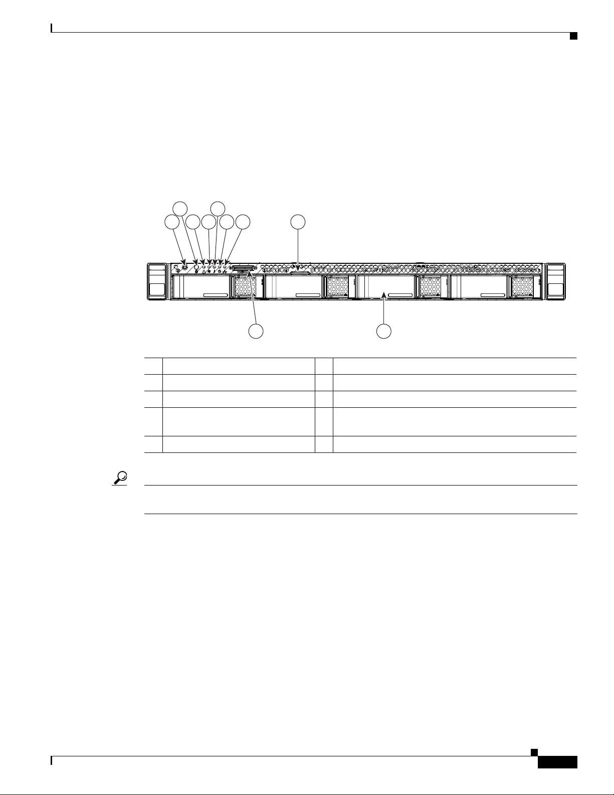
Figure 1-1 shows the front panel features of the LFF drives version of the server.
Figure 1-1 Cisco Connected Safety and Security UCS C220 Server Front Panel Features
System Overview
2
5
31
84 6 7
HDD1 HDD2 HDD3 HDD4
109
1 Power button/Power status LED 6 Power supply status LED
2 Identification button/LED 7 Network link activity LED
3 System status LED 8 Pull-out asset tag
4 Fan status LED 9 KVM connector (used with KVM cable that provides
wo USB, one VGA, and one serial connector)
t
5 Temperature status LED 10 Drives, hot-swappable (up to four 3.5-inch drives)
Tip See the “Cisco Connected Safety and Security UCS C220 LEDs and Buttons” section on page 1-10 for
more information.
331684
Cisco CSS UCS Platform Series User Guide, CPS-UCS-1RU-K9 / CPS-UCS-2RU-K9
1-3
Page 12
System Overview
PSU1PSU1 PSU2PSU2PSU1 PSU2
PCIe2
PCIe1
4 5 6 98
2 31
7
331683
Cisco Connected Safety and Security UCS C220 Rear Panel
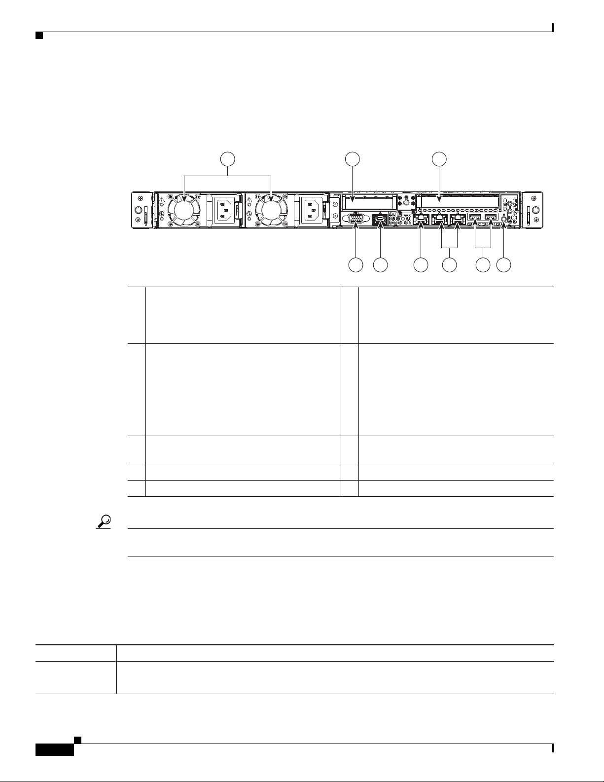
Figure 1-2 shows the rear panel features of the server.
Figure 1-2 Cisco Connected Safety and Security UCS C220 Server Rear Panel Features
1 Power supplies (up to two) 6 1-Gb Ethernet dedicated management port
2 Low-profile PCIe slot 2 on riser
(half-height, half-length, x8 lane)
Note The low-profile slots are not
supported in the Cisco Connected
Safety and Security UCS C220
(CPS-UCS-1RU-K9)
3 Standard-profile PCIe slot on riser
(full-height, half-length, x16 lane)
4 VGA video connector 9 Rear Identification button/LED
5 Serial port (RJ-45 connector) –
Chapter 1 Overview
Note The CIMC can be accessed only
through the 1Gb Ethernet dedicated
management port.
7 Dual 1-Gb Ethernet ports
(LAN1 and LAN2)
Note The LAN Ethernet posts are referred
to as “Eth 0” and “Eth1” in the Cisco
Connected Safety and Security
applications, such as Cisco Video
Surveillance.
8 USB ports
Tip See the “Cisco Connected Safety and Security UCS C220 LEDs and Buttons” section on page 1-10 for
more information.
Summary of Cisco Connected Safety and Security UCS C220 Server Features
Table 1-2 lists the features of the server.
.
Ta b l e 1-2 Cisco Connected Safety and Security UCS C220 Server Features
Chassis One rack-unit (1RU) chassis.
Processors A single Intel Xeon E5-2600 Series processor is supported.
CPU2 and associated DIMMs are not supported.
Cisco CSS UCS Platform Series User Guide, CPS-UCS-1RU-K9 / CPS-UCS-2RU-K9
1-4
Page 13

Chapter 1 Overview
Table 1-2 Cisco Connected Safety and Security UCS C220 Server Features (continued)
System Overview
Memory 8 BG of internal memory (DIMM
1
).
See the “DIMM Memory Configuration” section on page 1-20.
Baseboard
management
Pilot III BMC, running Cisco Integrated Management Controller (CIMC) firmware.
• The CIMC can be accessed only through the 1Gb Ethernet dedicated management port.
• See the “Cisco Integrated Management Interface (CIMC)” section on page 1-22 for more
information.
Network and
management I/O
The server provides these rear-panel connectors:
• One 1-Gb Ethernet dedicated management port
• Two 1-Gb Base-T Ethernet ports
Note The LAN Ethernet posts are referred to as “Eth 0” and “Eth1” in the Cisco Connected Safety and
Security applications, such as Cisco Video Surveillance.
• One RS-232 serial port (RJ-45 connector)
• One 15-pin VGA
• Two USB
• One front-panel KVM connector that is used with the included KVM cable, which provides two USB,
3
2
connector
2.0 connectors
one VGA, and one serial connector.
Power Up to two 650 W power supplies are supported, including 1+1 redundancy (the 450W is not supported).
Do not mix power supply types in the server.
See Power Specifications, page A-2 for more information on power supplies.
Cooling Five hot-swappable fan modules for front-to-rear cooling.
PCIe I/O Two horizontal PCIe
4
expansion slots on risers.
See the “Replacing a PCIe Card” section on page 4-13 more information.
Not Supported
Only standard-profile PCIe slots are supported. The low-profile slots are not supported
Stora ge Drives are installed into front-panel drive bays that provide hot-pluggable access. Only the Large Form
Factor is supported (the server can hold up to four 3.5-inch SAS or SATA hard drives).
Not Supported
• The Small Form Factor server is NOT supported.
• The internal USB 2.0 port on the motherboard is NOT supported.
• The optional Cisco Flexible Flash drive (SD card) is not supported.
Disk
Management
For a list of supported RAID5 options, see the application-specific details. For example, see the
“Supported RAID and Hard Drive Configurations (Cisco VSM)” section on page 2-3.
(RAID)
1. DIMM = dual inline memory module
2. VGA = video graphics array
3. USB = universal serial bus
4. PCIe = peripheral component interconnect express
5. RAID = redundant array of independent disks
Cisco CSS UCS Platform Series User Guide, CPS-UCS-1RU-K9 / CPS-UCS-2RU-K9
1-5
Page 14
System Overview
HDD 1
HDD 5
HDD 9
HDD 2
HDD 6
HDD 10
HDD 3
HDD 7
HDD 11
HDD 4
HDD 8
HDD 12
331825
4
5
6
7
8
10
9
3
2
1
Cisco Connected Safety and Security UCS C240 (2RU) Overview
The Cisco Connected Safety and Security UCS C240 (CPS-UCS-2RU-K9) is available in the large form
factor (LFF) only, which supports up to 12 3.5-inch hard drives.
Note The small form-factor (SFF) versions of the Cisco Connected Safety and Security UCS C240 are not
supported for Cisco Physical Security applications.
• Cisco Connected Safety and Security UCS C240 Front Panel, page 1-6
• Cisco Connected Safety and Security UCS C240 Rear Panel, page 1-7
• Summary of Cisco Connected Safety and Security UCS C240 Server Features, page 1-8
Cisco Connected Safety and Security UCS C240 Front Panel
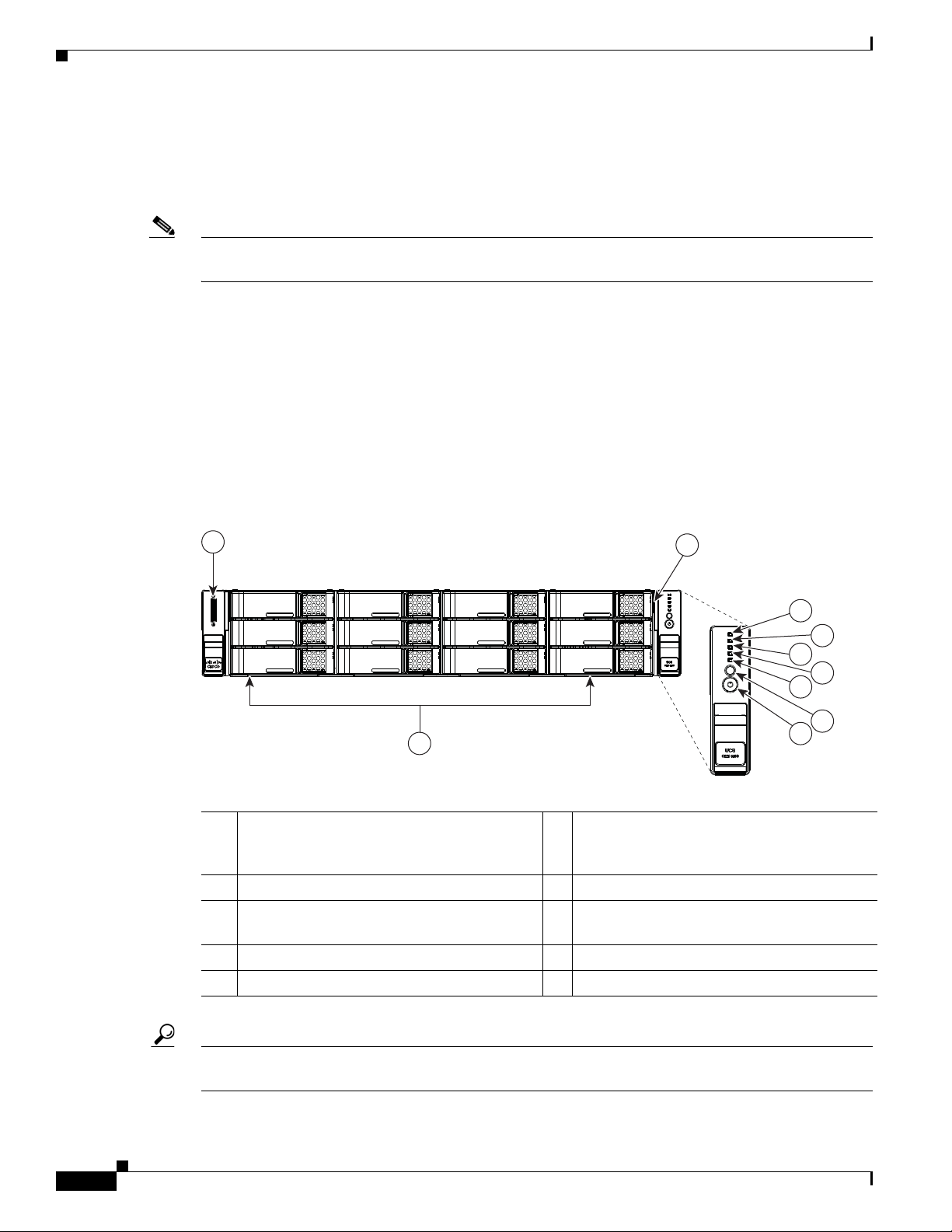
Figure 1-3 shows the front panel features of the Large Form-Factor drives version of the server. This
version of the server has a 12-drive.
Chapter 1 Overview
Figure 1-3 Cisco Connected Safety and Security UCS C240 Server Front Panel Features
1 KVM connector
6 Temperature status LED
(used with KVM cable that provides two
USB 2.0, one VGA, and one serial connector)
2 Pull-out asset tag 7 Fan status LED
3 Drives, hot-swappable
8 System status LED
(up to twelve 3.5-inch drives)
4 Network link activity LED 9 Identification button/LED
5 Power supply status LED 10 Power button/power status LED
1-6
Tip See the “Cisco Connected Safety and Security UCS C240 LEDs and Buttons” section on page 1-15 for
more information.
Cisco CSS UCS Platform Series User Guide, CPS-UCS-1RU-K9 / CPS-UCS-2RU-K9
Page 15

Chapter 1 Overview
PSU1 PSU2
PCIe 1
PCIe 2
PCIe 3
PCIe 4
PCIe 5
4 98 107 1165
2 3
331826
1
Note The backplane expander is not supported by the Cisco Connected Safety and Security UCS C240.
Cisco Connected Safety and Security UCS C240 Rear Panel
Figure 1-4 shows the rear panel features of the server.
Figure 1-4 Cisco Connected Safety and Security UCS C240 Server Rear Panel Features
System Overview
1 Power supplies (two) 7 1-Gb Ethernet dedicated management port
2 PCIe slot on riser 2:
8 USB 2.0 port
PCIe 5—full-height, 3/4-length, x16 lane)
Note The SD card slots on the PCIe riser
are NOT supported.
3 PCIe slot on riser 2:
PCIe 4—half-height, 3/4-length, x8 lane)
Note The SD card slots on the PCIe riser
are NOT supported.
9 Quad 1-Gb Ethernet ports
(LAN1 and LAN2)
Note Only LAN1 and LAN2 ports are
supported (referred to as “Eth 0” and
“Eth1” in the Cisco Connected Safety
and Security applications, such as Cisco
Video Surveillance).
Note The LAN3 and LAN4 ports are not
supported.
4 VGA video connector 10 PCIe slots on riser 1:
PCIe 1—full-height, half-length, x8 lane
PCIe 2—full-height, half-length, x16 lane
PCIe 3—full-height, half-length, x8 lane
5 Serial port (RJ-45 connector) 11 Rear Identification button/LED
6 USB port –
Tip See the “Cisco Connected Safety and Security UCS C240 LEDs and Buttons” section on page 1-15 for
more information.
Cisco CSS UCS Platform Series User Guide, CPS-UCS-1RU-K9 / CPS-UCS-2RU-K9
1-7
Page 16

System Overview
Summary of Cisco Connected Safety and Security UCS C240 Server Features
Table 1-3 lists a summary of server features.
.
Ta b l e 1-3 Cisco Connected Safety and Security UCS C240 Server Features
Chassis Two rack-unit (2RU) chassis.
Processors Two Intel Xeon E5-2600 Series processors.
Memory 8 BG of internal memory (DIMM
1
).
See the “DIMM Memory Configuration” section on page 1-20.
Baseboard
management
Pilot III BMC, running Cisco Integrated Management Controller (CIMC)
firmware.
• The CIMC can be accessed only through the 1Gb Ethernet dedicated
management port.
• See the “Cisco Integrated Management Interface (CIMC)” section on
page 1-22.
Network and
management I/O
The server provides these connectors:
• One 1-Gb Ethernet dedicated management port
• Two 1-Gb Base-T Ethernet LAN ports
Chapter 1 Overview
Note Only LAN1 and LAN2 ports are supported (referred to as “Eth 0” and
“Eth1” in the Cisco Connected Safety and Security applications, such as
Cisco Video Surveillance). The LAN3 and LAN4 ports are not supported.
• One RS-232 serial port (RJ-45 connector)
• One 15-pin VGA
• Two USB
• One front-panel KVM connector that is used with the included KVM cable,
3
2
connector
2.0 connectors
which provides two USB, one VGA, and one serial connector.
Power Two 650 W power supplies are supported, including 1+1 redundancy (the 1200 W
is not supported). Do not mix power supply types in the server.
See Power Specifications, page A-4.
Cooling Six hot-swappable fan modules for front-to-rear cooling.
PCIe I/O Five horizontal PCIe
4
expansion slots on two risers.
See Replacing a PCIe Card, page 4-13 for specifications of the slots.
1-8
Cisco CSS UCS Platform Series User Guide, CPS-UCS-1RU-K9 / CPS-UCS-2RU-K9
Page 17

Chapter 1 Overview
System Overview
Table 1-3 Cisco Connected Safety and Security UCS C240 Server Features (continued)
Stora ge Drives are installed into front-panel drive bays that provide hot-pluggable access.
Only the Large Form Factor is supported (the server can hold up to 12 3.5-inch SAS
or SATA hard drives).
Not Supported
• The Small Form Factor configurations are NOT supported.
• The internal USB 2.0 port on the motherboard is NOT supported.
• The optional Cisco Flexible Flash drive (SD card) are not supported
Disk
Management
(RAID)
1. DIMM = dual inline memory module
2. VGA = video graphics array
3. USB = universal serial bus
4. PCIe = peripheral component interconnect express
5. RAID = redundant array of independent disks
For a list of supported RAID5 options, see the application-specific information. For
example, see the “Supported RAID and Hard Drive Configurations (Cisco VSM)”
section on page 2-3.
Cisco CSS UCS Platform Series User Guide, CPS-UCS-1RU-K9 / CPS-UCS-2RU-K9
1-9
Page 18

Status LEDs and Buttons
Status LEDs and Buttons
This section describes the location and meaning of LEDs and buttons and includes the following topics:
• Cisco Connected Safety and Security UCS C220 LEDs and Buttons, page 1-10
• Cisco Connected Safety and Security UCS C240 LEDs and Buttons, page 1-15
Cisco Connected Safety and Security UCS C220 LEDs and Buttons
This section describes the location and meaning of LEDs and buttons and includes the following topics:
• Front Panel LEDs, page 1-10
• Rear Panel LEDs and Buttons, page 1-12
• Internal Diagnostic LEDs, page 1-14
Front Panel LEDs
Chapter 1 Overview
Figure 1-5 shows the front panel LEDs for the Cisco Connected Safety and Security UCS C220.
Figure 1-5 Cisco Connected Safety and Security UCS C220 Server Front Panel Features
1 Power button/Power status LED 7 Network link activity LED
2 Identification button/LED 8 Pull-out asset tag
3 System status LED 9 KVM connector (used with KVM cable that provides
wo USB, one VGA, and one serial connector)
t
4 Fan status LED 10 Drives, hot-swappable (up to four 3.5-inch drives)
5 Temperature status LED 11 Hard drive fault LED
6 Power supply status LED 12 Hard drive activity LED
1-10
Cisco CSS UCS Platform Series User Guide, CPS-UCS-1RU-K9 / CPS-UCS-2RU-K9
Page 19

Chapter 1 Overview
Status LEDs and Buttons
Table 1-4 defines the LED states for the Cisco Connected Safety and Security UCS C220.
Ta b l e 1-4 Front Panel LEDs, Definitions of States: Cisco Connected Safety and Security UCS C220
LED Name State
Power button/Power status LED • Off—There is no AC power to the server.
• Amber—The server is in standby power mode. Power is supplied only to the CIMC
and some motherboard functions.
• Green—The server is in main power mode. Power is supplied to all server
components.
Identification • Off—The Identification LED is not in use.
• Blue—The Identification LED is activated.
System status • Green—The server is running in normal operating condition.
• Green, blinking—The server is performing system initialization and memory check.
• Amber, steady—The server is in a degraded operational state. For example:
–
Power supply redundancy is lost.
–
CPUs are mismatched.
–
At least one CPU is faulty.
–
At least one DIMM is faulty.
–
At least one drive in a RAID configuration failed.
• Amber, blinking—The server is in a critical fault state. For example:
–
Boot failed.
–
Fatal CPU and/or bus error is detected.
–
Server is in over-temperature condition.
Fan status • Green—All fan modules are operating properly.
• Amber, steady—One fan module has failed.
• Amber, blinking—Critical fault, two or more fan modules have failed.
Temperature status • Green—The server is operating at normal temperature.
• Amber, steady—One or more temperature sensors have exceeded a warning
threshold.
• Amber, blinking—One or more temperature sensors have exceeded a critical
threshold.
Power supply status • Green—All power supplies are operating normally.
• Amber, steady—One or more power supplies are in a degraded operational state.
• Amber, blinking—One or more power supplies are in a critical fault state.
Network link activity • Off—The Ethernet link is idle.
• Green—One or more Ethernet LOM ports are link-active, but there is no activity.
• Green, blinking—One or more Ethernet LOM ports are link-active, with activity.
Cisco CSS UCS Platform Series User Guide, CPS-UCS-1RU-K9 / CPS-UCS-2RU-K9
1-11
Page 20

Chapter 1 Overview
PSU1PSU1 PSU2PSU2PSU1 PSU2
1
2 3 4 75 6
331692
Status LEDs and Buttons
Table 1-4 Front Panel LEDs, Definitions of States: Cisco Connected Safety and Security UCS C220 (continued)
LED Name State
Hard drive fault
Hard drive activity
• Off—The hard drive is operating properly.
• Amber—This hard drive has failed.
• Amber, blinking—The device is rebuilding.
• Off—There is no hard drive in the hard drive sled (no access, no fault).
• Green—The hard drive is ready.
• Green, blinking—The hard drive is reading or writing data.
Rear Panel LEDs and Buttons
Figure 1-6 shows the rear panel LEDs and buttons for the Cisco Connected Safety and Security UCS
C220.
Figure 1-6 Rear Panel LEDs and Buttons: Cisco Connected Safety and Security UCS C220
1 Power supply fault LED 5 1-Gb Ethernet link speed LED
2 Power supply AC OK LED 6 1-Gb Ethernet link status LED
3 1-Gb Ethernet dedicated management link
7 Rear Identification button/LED
status LED
4 1-Gb Ethernet dedicated management link
–
speed LED
Cisco CSS UCS Platform Series User Guide, CPS-UCS-1RU-K9 / CPS-UCS-2RU-K9
1-12
Page 21

Chapter 1 Overview
Status LEDs and Buttons
Table 1-5 defines the LED states for the Cisco Connected Safety and Security UCS C220.
Ta b l e 1-5 Rear Panel LEDs, Definitions of States: Cisco Connected Safety and Security UCS C220
LED Name State
Power supply fault
Power supply AC OK
1-Gb Ethernet dedicated
management l
ink speed
1-Gb Ethernet dedicated
management l
ink status
1-Gb Ethernet link speed
• Off—The power supply is operating normally.
• Amber, blinking—An event warning threshold has been reached, but the power
supply continues to operate.
• Amber, solid—A critical fault threshold has been reached, causing the power
supply to shut down (for example, a fan failure or an over-temperature condition).
• Off—There is no AC power to the power supply.
• Green, blinking—AC power OK, DC output not enabled.
• Green, solid—AC power OK, DC outputs OK.
• Off—link speed is 10 Mbps.
• Amber—link speed is 100 Mbps.
• Green—link speed is 1 Gbps.
• Off—No link is present.
• Green—Link is active.
• Green, blinking—Traffic is present on the active link.
• Off—link speed is 10 Mbps.
• Amber—link speed is 100 Mbps.
1-Gb Ethernet link status
Identification
• Green—link speed is 1 Gbps.
• Off—No link is present.
• Green—Link is active.
• Green, blinking—Traffic is present on the active link.
• Off—The Identification LED is not in use.
• Blue—The Identification LED is activated.
Cisco CSS UCS Platform Series User Guide, CPS-UCS-1RU-K9 / CPS-UCS-2RU-K9
1-13
Page 22

Status LEDs and Buttons
Internal Diagnostic LEDs
The server has internal fault LEDs for fan modules and DIMMs. An LED lights amber to indicate a failed
component.
Note Power must be connected to the server for these LEDs to be operate.
See Figure 1-7 for the locations of these internal LEDs.
Figure 1-7 Internal Diagnostic LED Locations: Cisco Connected Safety and Security UCS C220
Chapter 1 Overview
1 2
FAN4
1 Fan module fault LEDs (one next to each fan
connector on the motherboard)
2 DIMM fault LEDs (one next to each DIMM
socket on the motherboard)
Table 1-6 describes the LED states.
Ta b l e 1-6 Internal Diagnostic LEDs, Definition of States: Cisco Connected Safety and Security
UCS C220
LED Name State
Internal diagnostic LEDs (all)
• Off—Component is functioning normally.
• Amber—Component has failed.
331693
1-14
Cisco CSS UCS Platform Series User Guide, CPS-UCS-1RU-K9 / CPS-UCS-2RU-K9
Page 23

Chapter 1 Overview
Cisco Connected Safety and Security UCS C240 LEDs and Buttons
This section describes the location and meaning of LEDs and buttons and includes the following topics
• Front Panel LEDs, page 1-15
• Rear Panel LEDs and Buttons, page 1-17
• Internal Diagnostic LEDs, page 1-18
Front Panel LEDs
Figure 1-8 shows the front panel LEDs for the Cisco Connected Safety and Security UCS C240.
Figure 1-8 Cisco Connected Safety and Security UCS C240 Server Front Panel Features
Status LEDs and Buttons
1 KVM connector 7 Fan status LED
2 Pull-out asset tag 8 System status LED
3 Drives, hot-swappable
9 Identification button/LED
(up to twelve 3.5-inch drives)
4 Network link activity LED 10 Power button/power status LED
5 Power supply status LED 11 Hard drive fault LED
6 Temperature status LED 12 Hard drive activity LED
Table 1-7 defines the LED states.
Ta b l e 1-7 Front Panel LEDs, Definitions of States: Cisco Connected Safety and Security UCS C240
LED Name State
Hard drive fault
Hard drive activity
• Off—The hard drive is operating properly.
• Amber—This hard drive has failed.
• Amber, blinking—The device is rebuilding.
• Off—There is no hard drive in the hard drive sled (no access, no fault).
• Green—The hard drive is ready.
• Green, blinking—The hard drive is reading or writing data.
Cisco CSS UCS Platform Series User Guide, CPS-UCS-1RU-K9 / CPS-UCS-2RU-K9
1-15
Page 24

Chapter 1 Overview
Status LEDs and Buttons
Table 1-7 Front Panel LEDs, Definitions of States: Cisco Connected Safety and Security UCS C240 (continued)
LED Name State
Network link activity • Off—The Ethernet link is idle.
• Green—One or more Ethernet LOM ports are link-active, but there is no activity.
• Green, blinking—One or more Ethernet LOM ports are link-active, with activity.
Power supply status • Green—All power supplies are operating normally.
• Amber, steady—One or more power supplies are in a degraded operational state.
• Amber, blinking—One or more power supplies are in a critical fault state.
Temperature status • Green—The server is operating at normal temperature.
• Amber, steady—One or more temperature sensors have exceeded a warning
threshold.
• Amber, blinking—One or more temperature sensors have exceeded a critical
threshold.
Fan status • Green—All fan modules are operating properly.
• Amber, steady—One fan module has failed.
• Amber, blinking—Critical fault, two or more fan modules have failed.
System status • Green—The server is running in normal operating condition.
• Green, blinking—The server is performing system initialization and memory check.
• Amber, steady—The server is in a degraded operational state. For example:
–
Power supply redundancy is lost.
–
CPUs are mismatched.
–
At least one CPU is faulty.
–
At least one DIMM is faulty.
–
At least one drive in a RAID configuration failed.
• Amber, blinking—The server is in a critical fault state. For example:
–
Boot failed.
–
Fatal CPU and/or bus error is detected.
–
Server is in over-temperature condition.
Identification • Off—The Identification LED is not in use.
• Blue—The Identification LED is activated.
Power button/Power status LED • Off—There is no AC power to the server.
• Amber—The server is in standby power mode. Power is supplied only to the CIMC
and some motherboard functions.
• Green—The server is in main power mode. Power is supplied to all server
components.
1-16
Cisco CSS UCS Platform Series User Guide, CPS-UCS-1RU-K9 / CPS-UCS-2RU-K9
Page 25

Chapter 1 Overview
Rear Panel LEDs and Buttons
Figure 1-9 shows the rear panel LEDs and buttons.
Figure 1-9 Rear Panel LEDs and Buttons: Cisco Connected Safety and Security UCS C240
PSU1 PSU2
PCIe 5
Status LEDs and Buttons
PCIe 1
PCIe 4
PCIe 2
PCIe 3
331829
3 4 5 61 2
1 Power supply fault LED 5 1-Gb Ethernet link speed LED
2 Power supply AC OK LED 6 1-Gb Ethernet link status LED
3 1-Gb Ethernet dedicated management link
7 Identification button/LED
status LED
4 1-Gb Ethernet dedicated management link
–
speed LED
Table 1-8 defines the LED states.
Ta b l e 1-8 Rear Panel LEDs, Definitions of States: Cisco Connected Safety and Security UCS C240
LED Name State
Power supply fault
• Off—The power supply is operating normally.
• Amber, blinking—An event warning threshold has been reached, but the power
supply continues to operate.
• Amber, solid—A critical fault threshold has been reached, causing the power
supply to shut down (for example, a fan failure or an over-temperature condition).
Power supply AC OK
• Off—There is no AC power to the power supply.
• Green, blinking—AC power OK, DC output not enabled.
7
1-Gb Ethernet dedicated
management l
ink speed
1-Gb Ethernet dedicated
management l
ink status
1-Gb Ethernet link speed
• Green, solid—AC power OK, DC outputs OK.
• Off—link speed is 10 Mbps.
• Amber—link speed is 100 Mbps.
• Green—link speed is 1 Gbps.
• Off—No link is present.
• Green—Link is active.
• Green, blinking—Traffic is present on the active link.
• Off—link speed is 10 Mbps.
• Amber—link speed is 100 Mbps.
• Green—link speed is 1 Gbps.
Cisco CSS UCS Platform Series User Guide, CPS-UCS-1RU-K9 / CPS-UCS-2RU-K9
1-17
Page 26
Chapter 1 Overview
SAS2
SAS1
FAN1
FAN2
FAN3
FAN4
FAN5
FAN6
CPU1
CPU2
SAS1
SAS2
Riser 1
Riser 2
SAS2
SAS1
1 2
331830
Status LEDs and Buttons
Table 1-8 Rear Panel LEDs, Definitions of States: Cisco Connected Safety and Security UCS C240 (continued)
LED Name State
1-Gb Ethernet link status
Identification
• Off—No link is present.
• Green—Link is active.
• Green, blinking—Traffic is present on the active link.
• Off—The Identification LED is not in use.
• Blue—The Identification LED is activated.
Internal Diagnostic LEDs
The server is equipped with a SuperCap voltage source that can activate internal component fault LEDs
up to one half-hour after AC power is removed. The server has internal fault LEDs for fan modules and
DIMMs.
To use these LEDs to identify a faile
Figure 1-8 or Figure 1-9) with AC power removed. An LED lights amber to indicate a failed component.
d component, press the front or rear Identification button (see
See Figure 1-10 for the locations of these internal LEDs.
Figure 1-10 Inte rnal D iagnost ic LED Locations: Cisco Connected Safety and Security UCS C240
1-18
1 Fan module fault LEDs (one on each fan
module)
Cisco CSS UCS Platform Series User Guide, CPS-UCS-1RU-K9 / CPS-UCS-2RU-K9
2 DIMM fault LEDs (one next to each DIMM
socket on the motherboard)
Page 27

Chapter 1 Overview
Table 1-9 describes the LED states.
Ta b l e 1-9 Internal Diagnostic LEDs, Definition of States
LED Name State
Internal diagnostic LEDs (all)
• Off—Component is functioning normally.
• Amber—Component has failed.
Status LEDs and Buttons
Cisco CSS UCS Platform Series User Guide, CPS-UCS-1RU-K9 / CPS-UCS-2RU-K9
1-19
Page 28

Supported PSBU Hardware Configurations
Supported PSBU Hardware Configurations
• DIMM Memory Configuration, page 1-20
• Supported NIC (GigE) Ports (Cisco Video Surveillance), page 1-21
DIMM Memory Configuration
• Cisco Connected Safety and Security UCS C220 Memory, page 1-20
• Cisco Connected Safety and Security UCS C240 Memory, page 1-20
Cisco Connected Safety and Security UCS C220 Memory
The Cisco Connected Safety and Security UCS C220 (1RU) server is pre-configured with 8GB of system
memory. A single 8GB DIMM is installed in slot A1. (Figure 1-11).
Note DIMMs are not field replacable or upgradable in the Cisco Connected Safety and Security UCS series
servers.
Chapter 1 Overview
Note • Only CPU 1 (and the associated channels A, B, C, and D) are supported in this release.
Figure 1-11 DIMM Slot Numbering: Cisco Connected Safety and Security UCS C220
• CPU2 is not supported. Any DIMM modules installed in the CPU2-supported channels E, F, G, and
H will be ignored and unused by the server.
Cisco Connected Safety and Security UCS C240 Memory
The Cisco Connected Safety and Security UCS C240 (2RU) server is pre-configured with 16GB of
system memory. 8GB DIMM is installed in the slots associated with each CPU (CPU1 and CPU2).
Cisco CSS UCS Platform Series User Guide, CPS-UCS-1RU-K9 / CPS-UCS-2RU-K9
1-20
Page 29

Chapter 1 Overview
Front of Server
CPU 1
CPU 2
F3
F2
F1
E3
E2
E1
G1
G2
G3
H1
H2
H3
B3
B2
B1A3A2
A1
C1
C2
C3D1D2
D3
331840
Supported PSBU Hardware Configurations
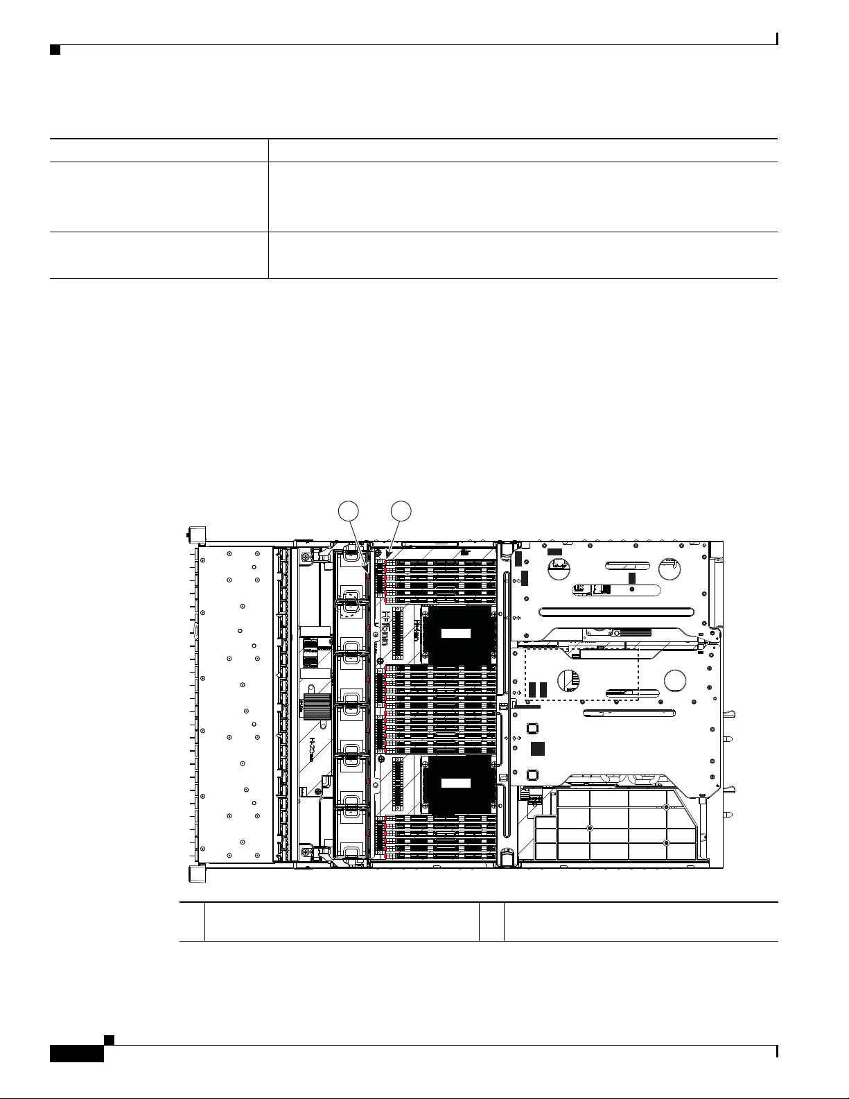
• CPU1—One 8GB DIMM is installed in slot A1 (Figure 1-12).
• CPU2—One 8GB DIMM is installed in slot E1.
Note DIMMs are not field replacable or upgradable in the Cisco Connected Safety and Security UCS series
servers.
Figure 1-12 CPUs and DIMM Slots on Motherboard: Cisco Connected Safety and Security UCS
C240
Supported NIC (GigE) Ports (Cisco Video Surveillance)
The Cisco Connected Safety and Security UCS series servers support the following:
• One 1-Gb Ethernet dedicated management port
• Two 1-Gb Base-T Ethernet ports
See the “System Overview” section on page 1-2 for port locations.
Note • The LAN Ethernet posts are referred to as “Eth 0” and “Eth1” in the Cisco Connected Safety and
Security applications, such as Cisco Video Surveillance.
• The Cisco Connected Safety and Security UCS series servers do NOT support the NIC redundancy
modes. Only the None option is supported: the Ethernet ports operate independently and do not fail
over if there is a problem.
Cisco CSS UCS Platform Series User Guide, CPS-UCS-1RU-K9 / CPS-UCS-2RU-K9
1-21
Page 30

Chapter 1 Overview
Server and Accessories Part Numbers
Server and Accessories Part Numbers
The following servers and field replaceable units (FRUs) are supported by the Cisco Connected Safety
and Security UCS Platform Series servers. Refer to these PIDs when ordering new or replacement
components.
Ta b l e 1-10 Part Numbers for the Cisco Connected Safety and Security UCS Platform Series
Ty pe Part Number (PID) Description
Server appliance CPS-UCS-1RU-K9= Cisco Connected Safety and Securi
CPS-UCS-2RU-K9= Cisco Connected Safety and Securi
Fiber Channel PCIe Cards
tional)
(Op
Hard Drives
Note You can order
drives in bundles
of 2 or 6 drives for
replacement or
expansion.
Bundles must be
the same capacity.
RAID CPS-RAID9271CV-8I= MegaRAID 9271CV Raid card with 8 internal SAS/SATA parts, S
Power Supplies CPS-PSU-650W= 650W power supply.
CPS-AEPCI05= Emulex LPe 12002 Dual Port 8Gb Fibre Channel HBA
CPS-HDD1TI2F212= 1TB SAS 7.2K RPM 3.5 inch HDD/hot plug/drive sled mounted
CPS-HDD2TI2F213= 2TB SAS 7.2K RPM 3.5 inch HDD/hot plug/drive sled mounted
CPS-HDD3TI2F214= 3TB SAS 7.2K RPM 3.5 inch HDD/hot plug/drive sled mounted
ty UCS C220 (1RU) server
ty UCS C240 (2RU) server
Server Monitoring and Management Tools
The following software tools are used to monitor server health and events:
• Cisco Integrated Management Interface (CIMC), page 1-22
• Cisco Video Surveillance Management Console, page 1-22
Cisco Integrated Management Interface (CIMC)
You can monitor the server inventory, health, and system event logs by using the built-in Cisco Integrated
Management Controller (CIMC) GUI or CLI interfaces. See the user documentation for your firmware
release at the following URL:
http://www.cisco.com/en/US/products/ps10739/products_installation_and_configuration_guides_list.html
For example: see the Cisco UCS C-Series Servers Integrated Management Controller GUI Configuration
Guide, Release 1.5.
Cisco Video Surveillance Management Console
For Cisco Video Surveillance Manager applications, use the browser-based Cisco VSM Management
Console to configure, manage and monitor the server.
1-22
Cisco CSS UCS Platform Series User Guide, CPS-UCS-1RU-K9 / CPS-UCS-2RU-K9
Page 31

Chapter 1 Overview
See the Cisco Video Surveillance Management Console Administration Guide for more information.
Supported Applications
The current release of the Cisco Connected Safety and Security UCS series servers support the Cisco
Video Surveillance Manager and associated servers and devices. See the following for more information:
• Supported Applications, page 2-1
• Related Documentation, page B-1
• The Cisco Video Surveillance 7 Documentation Roadmap available at
http://www.cisco.com/go/physicalsecurity/vsm/roadmap. This document provides descriptions and
links to Cisco Video Surveillance documentation, server and storage platform documentation, and
other related documentation.
Supported Applications
Cisco CSS UCS Platform Series User Guide, CPS-UCS-1RU-K9 / CPS-UCS-2RU-K9
1-23
Page 32

Supported Applications
Chapter 1 Overview
1-24
Cisco CSS UCS Platform Series User Guide, CPS-UCS-1RU-K9 / CPS-UCS-2RU-K9
Page 33

CHA P T ER
2
Supported Applications
The current release of the Cisco Connected Safety and Security UCS series servers support the following
application:
• Cisco Video Surveillance Manager, Release 7.2 and Higher, page 2-1
Cisco Video Surveillance Manager, Release 7.2 and Higher
• Overview, page 2-1
• Initial Setup Procedure, page 2-2
• Upgrading the Cisco VSM System Software, page 2-2
• Recovering the Cisco VSM System Software, page 2-2
• Supported RAID and Hard Drive Configurations (Cisco VSM), page 2-3
• Supported Hard Drives, page 2-5
• More Information, page 2-6
Overview
The current release of the Cisco Connected Safety and Security UCS series servers support the Cisco
Video Surveillance Manager (Cisco VSM) Release 7.2 and higher, including associated servers and
devices.
The Cisco Connected Safety and Security UCS C220 (1RU) and Cisco Connected Safety and Security
UCS C240 (2RU) servers are shipped as server appliances, meaning that the Cisco Video Surveillance
Manager system software is pre-loaded in a “bare-metal” configuration.
Note These servers do not currently support additional virtual machine (VM) installations. Virtual Machine
deployment is supported on separate Cisco UCS Express, and B-, C-, and E- Series platform servers. See
the
Cisco Video Surveillance Virtual Machine Deployment, Recovery and HA Guide for UCS Platforms
for more information.
Cisco CSS UCS Platform Series User Guide, CPS-UCS-1RU-K9 / CPS-UCS-2RU-K9
2-1
Page 34

Cisco Video Surveillance Manager, Release 7.2 and Higher
Initial Setup Procedure
To install and configure a Cisco Connected Safety and Security UCS series server appliance for the first
time, complete the following high-level steps:
Procedure
Step 1 Physically install the Cisco Connected Safety and Security UCS series server appliance.
See the “Installing the Server” section on page 3-1.
Step 2 Complete the initial server setup.
See the “Initial Server Setup” section on page 3-16.
Step 3 Use the browser-based Cisco Video Surveillance Management Console to complete the initial server
setup for the Cisco Video Surveillance Manager.
See the Cisco Video Surveillance Management Console Administration Guide.
Step 4 Use the browser-based Cisco Video Surveillance Operations Manager to configure additional server
options and Cisco VSM features.
See the Cisco Video Surveillance Operations Manager User Guide.
Chapter 2 Supported Applications
Upgrading the Cisco VSM System Software
To to update the Cisco VSM system software, use the browser-based Cisco VSM Operations Manager
or Cisco VSM Management Console to install the upgrade file that contains all required packages and
components.
Refer to the following for more information:
• Cisco VSM Release 7.6 and higher—See the Cisco Video Surveillance Install and Upgrade Guide
for your release.
• Cisco VSM Release 7.2 to 7.5— See the Server Upgrade section of Cisco Video Surveillance
Management Console Administration Guide for instructions to obtain and install system upgrades.
Recovering the Cisco VSM System Software
To create a bootable USB flash drive that can be used to recover an installation or perform a factory
installation of Cisco VSM 7, see the following:
• Cisco VSM Release 7.6 and higher—See the Cisco Video Surveillance Install and Upgrade Guide
for your release.
• Cisco VSM Release 7.2 to 7.5— See the Cisco Video Surveillance Manager Recovery Guide (Cisco
Connected Safety and Security UCS Platform Series).
2-2
Cisco CSS UCS Platform Series User Guide, CPS-UCS-1RU-K9 / CPS-UCS-2RU-K9
Page 35

Chapter 2 Supported Applications
The recovery options include the following:
Ta b l e 2-1 Recovery Options
Option Description
recovery Reinstalls the operating system.
factory Restores the server to the factory default settings:
Cisco Video Surveillance Manager, Release 7.2 and Higher
• Recorded video and configurations are preserved.
• RAID configurations are preserved (only the OS partitions are
formatted).
Note You must disconnect any external storage before using this option
• Reinstalls the operating system.
• Clears and reconfigures the RAID.
Caution This action deletes all data and video files.
factory_raid5 Restores a Cisco Connected Safety and S
ecurity UCS C240 server to the
factory default settings, including:
Note Valid only on the Cisco Connected Safety and Security UCS C240
with 6 or 12 internal drives.
Note You must disconnect any external storage before using this option.
• Reinstalls the operating system.
• Clears and reconfigures the RAID.
Caution This action deletes all data and video files.
rescue Boot to prompt from USB media. Use this option to recover a password or
for
other administrative tasks
Supported RAID and Hard Drive Configurations (Cisco VSM)
Table 2-2 defines the drive configurations supported by the Cisco Video Surveillance Manager. The
Cisco Connected Safety and Security UCS C220 serv
Connected Safety and Security UCS C240 server supports RAID levels 1, 5 and 6.
er supports RAID 1 and 5, while the Cisco
Ta b l e 2-2 Supported Drive Configurations
Cisco Connected Safety and
Security UCS C220
2 drives RAID 1
4 drives RAID 5
Cisco CSS UCS Platform Series User Guide, CPS-UCS-1RU-K9 / CPS-UCS-2RU-K9
2-3
Page 36

Cisco Video Surveillance Manager, Release 7.2 and Higher
Table 2-2 Supported Drive Configurations (continued)
Chapter 2 Supported Applications
Cisco Connected Safety and
Securit
y UCS C240
Requirements and Conditions
The following notes apply to drive configurations, recovery and expansion.
• All drives must be installed in the lowest numbered available slot.
• Hot Standby drives are not supported.
• Mixing RAID configurations is not supported. For example, 6 drives in RAID 6, and 6 drives in
RAID 5).
• RAID expansion is not supported during a “Recovery” installation (RAID configuration remains the
same during a “Recovery” installation).
• RAID configuration may be changed during a “Factory” reimage (note that all data will be lost
unless backed up prior to the procedure).
Supported RAID Upgrade Paths
Table 2-3 defines the supported paths to add additional drives.
Ta b l e 2-3 Supported Upgrade Paths
2 drives RAID 1
6 drives RAID 5 or RAID 6
12 drives RAID 5 or RAID 6
Cisco Connected
Safety and Securit
UCS C220
Cisco Connected
Safety and Securit
UCS C240
From To Notes
2 drives 4 Drives/RAID 5 RAID Change, Factory Reimage required
y
2 drives/RAID 1 6 Drives/RAID 5 RAID Change, Factory Reimage required
y
2 drives/RAID 1 6 Drives/RAID 6
2 drives/RAID 1 12 Drives/RAID 5
2 drives/RAID 1 12 Drives/RAID 6
6 drives/RAID 5 12 Drives/RAID 6
6 drives/RAID 6 12 Drives /RAID 5
6 drives/RAID 5 12 Drives (as 1 RAID Group)
AID 5
/R
6 drives/RAID 6 12 Drives (as 1 RAID Group)
AID 6
/R
Factory Reimage required.
Dynamic expansion of existing VD, /media
artitions not supported
p
2-4
Cisco CSS UCS Platform Series User Guide, CPS-UCS-1RU-K9 / CPS-UCS-2RU-K9
Page 37

Chapter 2 Supported Applications
Note You can order drives in bundles of 2 drives. The bundles are for replacement and for expansion to get to
four drives. These drives that are shipped are of the same capacity. They can be 1TB, 2TB, or 3TB. See
the “Server and Accessories Part Numbers” section on page 1-22 for more information.
Note RAID configuration changes require a “Factory” reimage. All data will be lost unless backed up prior to
the procedure.
Supported Hard Drives
You can order drives in bundles of 2 drives. The bundles are for replacement and for expansion to get to
four drives. These drives that are shipped are of the same capacity. They can be 1TB, 2TB, or 3TB.
Requirements for All Servers
• Drives are not rebuilt when the same drive is removed and reinserted. The removed drive must be
replaced with a new drive. The rebuild will start automatically.
Cisco Video Surveillance Manager, Release 7.2 and Higher
• All drives must be of the same capacity. Drives of different capacities are not supported (for
example, you cannot mix 1TB, 2TB and/or 3TB drives in the same server).
• Installation is supported only if all hard drives are in optimal state.
• You can order drives in bundles of 2 drives for replacement or expansion. See the “Server and
Accessories Part Numbers” section on page 1-22.
• See the “Replacing Hard Drives” section on page 4-9 for more information.
Cisco Connected Safety and Security UCS C220 Hard Disk Configuration
• The Cisco Connected Safety and Security UCS C220 server ships with 2 or 4 disk drives (other
combinations are not supported).
• Up to four large form factor (LFF) disk drives (3.5” hard drives) of 1TB, 2TB, and 3TB are
supported. These are driven directly from the RAID controller and do not require any expander.
• RAID levels 1, 5 are supported. See the “Supported RAID and Hard Drive Configurations (Cisco
VSM)” section on page 2-3.
Cisco Connected Safety and Security UCS C240 Hard Disk Configuration
• Cisco Connected Safety and Security UCS C240 server ships with 2 or 12 disk drives.
• Up to 12 large form factor (LFF) disk drives (3.5” hard drives) of 1TB, 2TB, and 3TB are supported.
These are driven directly from the RAID controller and do not require any expander.
• RAID levels 1, 5 and 6 are supported. See the “Supported RAID and Hard Drive Configurations
(Cisco VSM)” section on page 2-3.
Cisco CSS UCS Platform Series User Guide, CPS-UCS-1RU-K9 / CPS-UCS-2RU-K9
2-5
Page 38

Cisco Video Surveillance Manager, Release 7.2 and Higher
More Information
See the following for more information:
• Related Documentation, page B-1
• The Cisco Video Surveillance 7 Documentation Roadmap available at
http://www.cisco.com/go/physicalsecurity/vsm/roadmap. This document provides descriptions and
links to Cisco Video Surveillance documentation, server and storage platform documentation, and
other related documentation.
Chapter 2 Supported Applications
2-6
Cisco CSS UCS Platform Series User Guide, CPS-UCS-1RU-K9 / CPS-UCS-2RU-K9
Page 39

CHA P T ER
3
Installing the Server
This chapter describes how to install the server, and it includes the following sections:
• Unpacking and Inspecting the Server, page 3-2
• Preparing for Server Installation, page 3-3
• Installing the Cisco Connected Safety and Security UCS C220 Server In a Rack, page 3-5
• Installing the Cisco Connected Safety and Security UCS C240 Server In a Rack, page 3-9
• Initial Server Setup, page 3-16
• System BIOS and CIMC Firmware, page 3-18
• Updating the BIOS and CIMC Firmware, page 3-18
Note Before you install, operate, or service a server, review the Regulatory Compliance and Safety
Information for Cisco UCS C-Series Servers for important safety information.
Warning
IMPORTANT SAFETY INSTRUCTIONS
This warning symbol means danger. You are in a situation that could cause bodily injury. Before you
work on any equipment, be aware of the hazards involved with electrical circuitry and be familiar
with standard practices for preventing accidents. Use the statement number provided at the end of
each warning to locate its translation in the translated safety warnings that accompanied this device.
Statement 1071
SAVE THESE INSTRUCTIONS
Cisco CSS UCS Platform Series User Guide, CPS-UCS-1RU-K9 / CPS-UCS-2RU-K9
3-1
Page 40

Unpacking and Inspecting the Server
Unpacking and Inspecting the Server
Caution When handling internal server components, wear an ESD strap and handle modules by the carrier edges
only.
Tip Keep the shipping container in case the server requires shipping in the future.
Note The chassis is thoroughly inspected before shipment. If any damage occurred during transportation or
any items are missing, contact your customer service representative immediately.
To inspect the shipment, follow these steps:
Step 1 Remove the server from its cardboard container and save all packaging material.
Step 2 Compare the shipment to the equipment list provided by your customer service representative and
Figure 3-1. Verify that you have all items.
Chapter 3 Installing the Server
Step 3 Check for damage and report any discrepancies or damage to your customer service representative. Have
the following information ready:
• Invoice number of shipper (see the packing slip)
• Model and serial number of the damaged unit
• Description of damage
• Effect of damage on the installation
Figure 3-1 Shipping Box Contents
3-2
1 Server 3 Documentation
2 Power cord (optional, up to two) 4 KVM cable
Cisco CSS UCS Platform Series User Guide, CPS-UCS-1RU-K9 / CPS-UCS-2RU-K9
Page 41

Chapter 3 Installing the Server
Preparing for Server Installation
This section provides information about preparing for server installation, and it includes the following
topics:
• Installation Guidelines, page 3-3
• Rack Requirements, page 3-4
• Equipment Requirements, page 3-4
• Slide Rail Adjustment Range, page 3-4
Installation Guidelines
Preparing for Server Installation
Warning
Warning
Warning
Warning
Caution Do not block the air vents on the top of the server’s cover. Do not stack another server directly on top of
To prevent the system from overheating, do not operate it in an area that exceeds the maximum
recommended ambient temperature of: 40° C (104° F).
Statement 1047
The plug-socket combination must be accessible at all times, because it serves as the main
disconnecting device.
Statement 1019
This product relies on the building’s installation for short-circuit (overcurrent) protection. Ensure that
the protective device is rated not greater than: 250 V, 15 A.
Statement 1005
Installation of the equipment must comply with local and national electrical codes.
Statement 1074
the C220 server. Doing so blocks the proper airflow, which could result in overheating, higher fan
speeds, and higher power consumption.
Caution Avoid UPS types that use ferroresonant technology. These UPS types can become unstable with systems
such as the Cisco UCS, which can have substantial current draw fluctuations from fluctuating data traffic
patterns.
When you are installing a server, use the following guidelines:
• Plan your site configuration and prepare the site before installing the server. See the Cisco UCS Site
Preparation Guide for the recommended site planning tasks.
• Ensure that there is adequate space around the server to allow for servicing the server and for
adequate airflow. The airflow in this server is from front to back.
Cisco CSS UCS Platform Series User Guide, CPS-UCS-1RU-K9 / CPS-UCS-2RU-K9
3-3
Page 42

Preparing for Server Installation
• Ensure that the air-conditioning meets the thermal requirements listed in the “Server
Specifications”.
• Ensure that the cabinet or rack meets the requirements listed in the “Rack Requirements” section on
page 3-4.
• Ensure that the site power meets the power requirements listed in the “Server Specifications”. If
available, you can use an uninterruptible power supply (UPS) to protect against power failures.
Rack Requirements
This section provides the requirements for the standard open racks.
The rack must be of the following type:
• A standard 19-in. (48.3-cm) wide, four-post EIA rack, with mounting posts that conform to English
universal hole spacing, per section 1 of ANSI/EIA-310-D-1992.
• The rack post holes can be square 0.38-inch (9.6 mm), round 0.28-inch (7.1 mm), #12-24 UNC, or
#10-32 UNC when you use the supplied slide rails.
• The minimum vertical rack space per server must be the following:
–
Chapter 3 Installing the Server
Cisco Connected Safety and Security UCS C220 (1RU): one RU, equal to 1.75 in. (44.45 mm).
–
Cisco Connected Safety and Security UCS C240 (2RU): The minimum vertical rack space per
server must be two RUs, equal to 3.5 in. (88.9 mm).
Equipment Requirements
Cisco Connected Safety and Security UCS C220 (1RU)
The slide rails supplied by Cisco Systems for this server do not require tools for installation. The inner
rails (mounting brackets) are pre-attached to the sides of the server.
Cisco Connected Safety and Security UCS C240 (2RU)
The slide rails supplied by Cisco Systems for this server do not require tools for installation if you install
them in a rack that has square 0.38-inch (9.6 mm), round 0.28-inch (7.1 mm), or #12-24 UNC threaded
holes. The inner rails are pre-attached to the sides of the server.
However, if you install the slide rails in a rack that has #10-32 round holes, a bladed screwdriver is
required to remove the larger square/round mounting pegs from the front of the slide rails.
Slide Rail Adjustment Range
The slide rails for this server have an adjustment range of 24 to 36 inches (610 to 914 mm).
3-4
Cisco CSS UCS Platform Series User Guide, CPS-UCS-1RU-K9 / CPS-UCS-2RU-K9
Page 43

Chapter 3 Installing the Server
Installing the Cisco Connected Safety and Security UCS C220 Server In a Rack
Installing the Cisco Connected Safety and Security UCS C220
Server In a Rack
This section describes how to install the server in a rack.
Warning
To prevent bodily injury when mounting or servicing this unit in a rack, you must take special
precautions to ensure that the system remains stable. The following guidelines are provided to ensure
your safety:
This unit should be mounted at the bottom of the rack if it is the only unit in the rack.
When mounting this unit in a
at the bottom of the rack.
If the rack is provided with stabilizing devices, install the stabilizers before mounting or servicing the unit in the rack.
partially filled rack, load the rack from the bottom to the top with the heaviest component
Statement 1006
To install the slide rails and the server into a rack, follow these steps:
Step 1 Open the front securing latch (see Figure 3-2). The end of the slide-rail assembly marked “FRONT” has
a spring-loaded securing latch that must be open before y
ou can insert the mounting pegs into the
rack-post holes.
a. On the rear side of the securing-latch assembly, hold open the clip marked “PULL.”
b. Slide the spring-loaded securing latch away from the mounting pegs.
c. Release the clip marked “PULL” to lock the securing latch in the open position.
Figure 3-2 Front Securing Latch
1
3
2
332061
1 Clip marked “PULL” on rear of assembly 3 Spring-loaded securing latch on front of
assembly
2 Front mounting pegs --
Cisco CSS UCS Platform Series User Guide, CPS-UCS-1RU-K9 / CPS-UCS-2RU-K9
3-5
Page 44

Installing the Cisco Connected Safety and Security UCS C220 Server In a Rack
331689
1
3
2
5
6
4
Step 2 Install the slide rails onto the rack:
a. Position a slide-rail assembly inside the two left-side rack posts (see Figure 3-3).
Chapter 3 Installing the Server
Use the “FRONT” and “REAR” markings on the slide-rail assem
bly to orient the assembly correctly
with the front and rear rack posts.
b. Position the front mounting pegs so that they enter the desired front rack-post holes from the front.
Note The mounting pegs that protrude through the rack-post holes are designed to fit round or square holes,
or smaller #10-32 round holes when the mounting peg is compressed. If your rack has #10-32 rack-post
holes, align the mounting pegs with the holes and then compress the spring-loaded pegs to expose the
#10-32 inner peg.
c. Expand the length-adjustment bracket until the rear mounting pegs protrude through the desired
holes in the rear rack post.
Use your finger to hold the rear securing latch open when you insert the rear mounting pegs to their
holes. W
Figure 3-3 Attaching a Slide-Rail Assembly
hen you release the latch, it wraps around the rack post and secures the slide-rail assembly.
1 Front-left rack post 4 Length-adjustment bracket
2 Front mounting pegs 5 Rear mounting pegs
3 Slide-rail assembly 6 Rear securing latch
d. Attach the second slide-rail assembly to the opposite side of the rack. Ensure that the two slide-rail
assemblies are level and at the same height with each other.
e. Pull the inner slide rails on each assembly out toward the rack front until they hit the internal stops
Step 3 Insert the server into the slide rails:
Cisco CSS UCS Platform Series User Guide, CPS-UCS-1RU-K9 / CPS-UCS-2RU-K9
3-6
and lock in place.
Page 45

Chapter 3 Installing the Server
7
331690
6
5
4
3
1
2
Note The inner rails are pre-attached to the sides of the server at the factory. You can order
a. Align the inner rails that are pre-attached to the server sides with the front ends of the empty slide
b. Push the server into the slide rails until it stops at the internal stops.
c. Push in the plastic release clip on each inner rail (labelled PUSH), and then continue pushing the
Step 4 Attach the (optional) cable management arm (CMA) to the rear of the slide rails:
Note The CMA is designed for mounting on either the right or left slide rails. These instructions
a. Slide the plastic clip on the inner CMA arm over the flange on the mounting bracket that attached
Installing the Cisco Connected Safety and Security UCS C220 Server In a Rack
replacement inner rails if these are damaged or lost (Cisco PID UCSC-RAIL1-I).
rails.
server into the rack until its front latches engage the rack posts.
describe an installation to the rear of the right slide rails, as viewed from the rear of server.
to the side of the server. See Figure 3-4.
Note Whether you are mounting the CMA to the left or right slide rails, be sure to orient the engraved
marking, “UP” so that it is always on the upper side of the CMA. See Figure 3-4.
b. Slide the plastic clip on the outer CMA arm over the flange on the slide rail. See Figure 3-4.
c. Attach the CMA retaining bracket to the left slide rail. Slide the plastic clip on the bracket over the
flange on the end of the left slide rail. See Figure 3-4.
Figure 3-4 Attaching the Cable Management Arm (Rear of Server Shown)
1 Flange on rear of outer left slide rail 5 Inner CMA arm attachment clip
2 CMA retaining bracket 6 “UP” orientation marking
3 Flange on rear of right mounting bracket 7 Outer CMA arm attachment clip
4 Flange on rear of outer right slide rail
Cisco CSS UCS Platform Series User Guide, CPS-UCS-1RU-K9 / CPS-UCS-2RU-K9
3-7
Page 46

Installing the Cisco Connected Safety and Security UCS C220 Server In a Rack
Step 5 Continue with the “Initial Server Setup” section on page 3-16.
Chapter 3 Installing the Server
3-8
Cisco CSS UCS Platform Series User Guide, CPS-UCS-1RU-K9 / CPS-UCS-2RU-K9
Page 47

Chapter 3 Installing the Server
Installing the Cisco Connected Safety and Security UCS C240 Server In a Rack
Installing the Cisco Connected Safety and Security UCS C240
Server In a Rack
This section contains the following sections:
• Installing the Slide Rails, page 3-9
• Installing the Cable Management Arm (Optional), page 3-12
• Reversing the Cable Management Arm (Optional), page 3-14
Installing the Slide Rails
Warning
Step 1 Install the slide rails into the rack (see Figure 3-3):
To prevent bodily injury when mounting or servicing this unit in a rack, you must take special
precautions to ensure that the system remains stable. The following guidelines are provided to ensure
your safety:
This unit should be mounted at the bottom of the rack if it is the only unit in the rack.
When mounting this unit in a partially filled rack, load the rack from the bottom to the top with the heaviest component
at the bottom of the rack.
If the rack is provided with stabilizing devices, install the stabilizers before mounting or servicing the unit in the rack.
Statement 1006
To install the slide rails and the server into a rack, follow these steps:
a. Align the slide-rail assembly inside the rack posts with the length-adjustment bracket (Figure 3-3,
item 4) toward the rear of the rack.
b. Compress the length-adjustment bracket until the mounting pegs (item 5) and locking clips (item 6)
engage the desired rack holes on the front and rear rack posts.
–
–
The mounting pegs fit square 0.38-inch (9.6 mm), round 0.28-inch (7.1 mm), or #12-24 UNC
threaded holes. They fit the shape of the hole when the pegs are compressed.
The smaller #10-32 round mounting pegs are enclosed in the center of the compressible rear
pegs. However, to use the #10-32 pegs, you must use a bladed screwdriver to remove the
square/round front pegs.
Cisco CSS UCS Platform Series User Guide, CPS-UCS-1RU-K9 / CPS-UCS-2RU-K9
3-9
Page 48

Installing the Cisco Connected Safety and Security UCS C240 Server In a Rack
Figure 3-5 Attaching a Slide-Rail Assembly
1 2
Chapter 3 Installing the Server
3
4
5
66
1 Front-right rack post 4 Length-adjustment bracket
2 Rear-right rack post 5 Mounting pegs (two on each end of assembly)
3 Slide-rail assembly 6 Locking clips (one on each end of assembly)
c. Attach the second slide-rail assembly to the opposite side of the rack. Ensure that the two slide-rail
assemblies are level and at the same height with each other.
d. Pull the inner slide rails on each assembly out toward the rack front until they hit the internal stops
and lock in place.
Step 2 Insert the server into the slide rails (see Figure 3-6):
Caution This server weighs approximately 60 pounds (28 kilograms) when fully loaded with components. We
recommend that you use a minimum of two people when lifting the server. Attempting this procedure
alone could result in personal injury or equipment damage.
330499
3-10
Note The inner rails are pre-attached to the sides of the server at the factory. You can order
replacement inner rails if these are damaged or lost (Cisco PID UCSC-RAIL-2U-I).
a. Align the inner rails that are attached to the server sides with the front ends of the empty slide rails.
b. Push the server into the slide rails until it stops at the internal stops.
c. Push in the slide rail locking clip (item 2) on each inner rail, and then continue pushing the server
into the rack until its front flanges latch onto the rack posts.
Cisco CSS UCS Platform Series User Guide, CPS-UCS-1RU-K9 / CPS-UCS-2RU-K9
Page 49

Chapter 3 Installing the Server
Figure 3-6 Inserting the Server Into the Slide Rails
1 Inner rail on server 3 Slide rail assembly on rack post
2 Slide rail locking clip 4 Right-front rack post
Installing the Cisco Connected Safety and Security UCS C240 Server In a Rack
3
2
1
4
330534
Step 3 Optional–If you want to install the cable management arm, continue with Installing the Cable
Management Arm (Optional), page 3-12.
Cisco CSS UCS Platform Series User Guide, CPS-UCS-1RU-K9 / CPS-UCS-2RU-K9
3-11
Page 50

Installing the Cisco Connected Safety and Security UCS C240 Server In a Rack
Installing the Cable Management Arm (Optional)
To install the cable management arm (CMA) to the rear of the slide rails, use the following procedure.
Note The CMA is reversible right-to-left. However when reversing, you must remove and reposition
the CMA attachment tabs for correct installation. To reverse the CMA, see
Management Arm (Optional), page 3-14 before installation.
Note When positioning the CMA, make sure that the CMA is correctly oriented with the “TOP” stamp
on the CMA arms facing upward. See Figure 3-4.
Step 1 With the server pushed fully into the rack, insert the outer CMA tab into the clip inside the rear of the
outer slide rail. Insert the tab into the clip until it clicks and locks.
Step 2 Pull outward on the spring-loaded peg that is on the inner CMA tab. You can turn this peg 90 degrees to
lock it in the open position.
Step 3 Push the inner CMA tab over the end of the inner rail that is attached to the server, and then release the
spring-loaded peg.
Chapter 3 Installing the Server
Reversing the Cable
The spring-loaded peg must align with and enter the hole in the inner rail to lock the CMA in place. If
you turned the peg 90 degrees to lock it open, now turn it back 90 degrees to release it.
3-12
Cisco CSS UCS Platform Series User Guide, CPS-UCS-1RU-K9 / CPS-UCS-2RU-K9
Page 51

Chapter 3 Installing the Server
TOP VIEW
SIDE VIEW
2
4
1
4
1
3
3
2
350825
Figure 3-7 Attaching the Cable Management Arm
Installing the Cisco Connected Safety and Security UCS C240 Server In a Rack
1 Outer CMA tab attached to outer slide rail 3 Rear of right slide rail assembly
2 Inner CMA tab with spring-loaded peg
attached to
inner rail
4 “TOP” stamp on CMA arms facing upward
Cisco CSS UCS Platform Series User Guide, CPS-UCS-1RU-K9 / CPS-UCS-2RU-K9
3-13
Page 52

Installing the Cisco Connected Safety and Security UCS C240 Server In a Rack
Reversing the Cable Management Arm (Optional)
The CMA is shipped assembled for installation to the rear of the right-hand slide rails (when facing the
rear of the server). The CMA is reversible so that you can mount it to the rear of either the right or left
slide rails. However, you must remove and reposition the CMA tabs so that the hinges open correctly.
To reverse the CMA, use the following procedure:
Step 1 Orient the CMA so that the “TOP” stamp on the CMA arms are facing upward (see Figure 3-8).
Step 2 Reverse the entire CMA assembly 180 degrees, kee ping the “TOP” stamp on the CMA arms facing
upward.
Step 3 Loosen the captive thumbscrew on each CMA arm.
Step 4 Remove the CMA tab from each arm.Slide the CMA tab forward until its pegs can be removed from the
keyed holes on the CMA arms.
Step 5 Install the inner CMA tab with the spring-loaded peg onto the CMA arm that is closest to the server (the
inner CMA arm). The tab fits onto the side of the arm that is opposite the captive thumbscrew.
a. Insert the pegs on the CMA tab into the keyed holes on the CMA arm and slide the tab to lock the
pegs in place.
Chapter 3 Installing the Server
b. Tighten the captive thumbscrew.
Step 6 Install the CMA tab with no spring-loaded tab onto the CMA arm that is farthest from the server (the
outer CMA arm).The tab fits onto the side of the arm that is opposite the captive thumbscrew.
a. Insert the pegs on the CMA tab into the keyed holes on the CMA arm and slide the tab to lock the
pegs in place.
b. Tighten the captive thumbscrew.
Step 7 Install the CMA to the sli de rails using the procedure in Installing the Cab le Manageme nt Arm
(Optional), page 3-12.
3-14
Cisco CSS UCS Platform Series User Guide, CPS-UCS-1RU-K9 / CPS-UCS-2RU-K9
Page 53

Chapter 3 Installing the Server
Orientation for mounting to left slide rail
Orientation for mounting to right slide rail
3
3
1
1
2
2
4
4
Figure 3-8 Reversing the Cable Management Arm
Installing the Cisco Connected Safety and Security UCS C240 Server In a Rack
1 “TOP” stamp on CMA arms 3 Inner CMA tab attaches to CMA arm closest
to server
2 Captive thumbscrews on CMA arms 4 Outer CMA tab attaches to CMA arm farthest
from serv
er
Cisco CSS UCS Platform Series User Guide, CPS-UCS-1RU-K9 / CPS-UCS-2RU-K9
3-15
Page 54

Initial Server Setup
Initial Server Setup
This section includes the following topics:
• Connecting and Powering On the Server (Standalone Mode), page 3-16
• System BIOS and CIMC Firmware, page 3-18
Connecting and Powering On the Server (Standalone Mode)
This section describes how to power on the server, assign an IP address, and connect to server
management when using the server in standalone mode.
Note UCS integration mode is not supported.
Procedure
Chapter 3 Installing the Server
Step 1 Attach a supplied power cord to each power supply in your server, and then attach the power cord to a
grounded AC power outlet. See the
Wait for approximately two minutes to let the server boot in standby power during the first bootup.
You can verify power status by looking at the Power Status LED (see the front panel illustrations in
Figure 1-1 and Figure 1-3):
• Off—There is no AC power present in the server.
• Amber—The server is in standby power mode. Power is supplied only to the CIMC and some
motherboard functions.
• Green—The server is in main power mode. Power is supplied to all server components.
Note During bootup, the server beeps once for each USB device that is attached to the server. Even if
there are no external USB devices attached, there is a short beep for each virtual USB device
such as a virtual floppy drive, CD/DVD drive, keyboard, or mouse. A beep is also emitted if a
USB device is hot-plugged or hot-unplugged during BIOS power-on self test (POST), or while
you are accessing the BIOS Setup utility or the EFI shell.
Step 2 Connect a USB keyboard and VGA monitor by using the supplied KVM cable connected to the KVM
connector on the front panel (see the front panel illustrations in
Note Alternatively, you can use the VGA and USB ports on the rear panel. However, you cannot use
the front panel VGA and the rear panel VGA at the same time. If you are connected to one VGA
connector and you then connect a video device to the other connector, the first VGA connector
is disabled.
“Server Specifications” for power specifications.
Figure 1-1 and Figure 1-3).
3-16
Step 3 Set NIC mode to Dedicated and choose whether to enable DHCP or set static network settings:
a. Press the Power button to boot the server. Watch for the prompt to press F8.
Cisco CSS UCS Platform Series User Guide, CPS-UCS-1RU-K9 / CPS-UCS-2RU-K9
Page 55

Chapter 3 Installing the Server
b. During bootup, press F8 when prompted to open the BIOS CIMC Configuration Utility. Verify that
Note The other NIC modes are NOT supported. For example: Shared LOM EXT, Shared LOM and
c. Verify that the NIC redundancy setting is None (default):
Note The NIC redundancy modes Active-standby and Active-active are NOT supported.
d. Choose whether to enable DHCP for dynamic network settings, or to enter static network settings.
Note Before you enable DHCP, your DHCP server must be pre-configured with the range of MAC
Initial Server Setup
the NIC mode is set to Dedicated (default) to indicate that the 1GE management port is used to
access the CIMC for server management (see the rear panel illustrations in
Figure 1-4 for identification of the ports).
Cisco Card.
addresses for this server. The MAC address is printed on a label on the rear of the server. This
server has a range of six MAC addresses assigned to the CIMC. The MAC address printed on
the label is the beginning of the range of six contiguous MAC addresses.
Figure 1-2 and
e. (Optional) Use this utility to make VLAN settings, and to set a default CIMC user password.
Note Changes to the settings take effect after approximately 45 seconds. Refresh with F5 and wait
until the new settings appear before you reboot the server in the next step.
f. Press F10 to save your settings and reboot the server.
Note If you chose to enable DHCP, the dynamically assigned IP and MAC addresses are displayed on
the console screen during bootup.
Step 4 Connect to the CIMC for server management. Connect Ethernet cables from your LAN to the server 1
GE management port (
Step 5 Use a browser and the IP address of the CIMC to connect to the CIMC Setup Utility. The IP address is
based upon the settings that you made in
Figure 1-2 and Figure 1-4 for identification of the ports).
Step 3 (either a static address or the address assigned by your
DHCP server).
Note The default user name for the server is admin. The default password is password.
To manage the server, see the Cisco UCS C-Series Rack-Mount Server Configuration Guide or the Cisco
UCS C-Series Rack-Mount Server CLI Configuration Guide for instructions on using those interfaces.
The links to these documents are in the C-Series documentation roadmap:
http://www.cisco.com/go/unifiedcomputing/c-series-doc
Cisco CSS UCS Platform Series User Guide, CPS-UCS-1RU-K9 / CPS-UCS-2RU-K9
3-17
Page 56

System BIOS and CIMC Firmware
System BIOS and CIMC Firmware
This section includes information about the system BIOS and it includes the following sections:
• Updating the BIOS and CIMC Firmware, page 3-18
• Accessing the System BIOS, page 3-19
Updating the BIOS and CIMC Firmware
Caution When you upgrade the BIOS firmware, you must also upgrade the CIMC firmware to the same version
or the server will not boot. Do not power off the server until the BIOS and CIMC firmware are matching
or the server will not boot.
Cisco provides the Cisco Host Upgrade Utility to assist with simultaneously upgrading the BIOS, CIMC,
and other firmware to compatible levels.
Chapter 3 Installing the Server
The server uses firmware obtained from and certified by Cisco. Cisco provides release notes with each
firmware image. There are several methods for updating the firmware:
• Recommended method for systems running firmware level 1.2 or later: Use the Cisco Host
Upgrade Utility to simultaneously upgrade the CIMC, BIOS, LOM, LSI storage controller, and
Cisco UCS P81E VIC firmware to compatible levels.
See the Cisco Host Upgrade Utility Quick Reference Guide for your firmware level at the
documentation roadmap link below.
Note Your system firmware must be at minimum level 1.2 to use the Cisco Host Upgrade Utility. If
your firmware is prior to level 1.2, you must use the methods below to update the BIOS and
CIMC firmware individually.
• You can upgrade the BIOS using the EFI interface, or upgrade from a Windows or Linux platform.
See the Cisco UCS C-Series Rack-Mount Server BIOS Upgrade Guide.
• You can upgrade the CIMC and BIOS firmware by using the CIMC GUI interface.
See the Cisco UCS C-Series Rack-Mount Server Configuration Guide.
• You can upgrade the CIMC and BIOS firmware by using the CIMC CLI interface.
See the Cisco UCS C-Series Rack-Mount Server CLI Configuration Guide.
For links to the documents listed above, see the documentation roadmap at the following URL:
http://www.cisco.com/go/unifiedcomputing/c-series-doc
3-18
Cisco CSS UCS Platform Series User Guide, CPS-UCS-1RU-K9 / CPS-UCS-2RU-K9
Page 57

Chapter 3 Installing the Server
Accessing the System BIOS
To change the BIOS settings for your server, follow these steps. Detailed instructions are also printed on
the BIOS screens.
Step 1 Enter the BIOS setup utility by pressing the F2 key when prompted during bootup.
Note The version and build of the current BIOS are displayed on the Main page of the utility.
Step 2 Use the arrow keys to select the BIOS menu page.
Step 3 Highlight the field to be modified by using the arrow keys.
Step 4 Press Enter to select the field that you want to change, and then modify the value in the field.
Step 5 Press the right arrow key until the Exit menu screen is displayed.
Step 6 Follow the instructions on the Exit menu screen to save your changes and exit the setup utility (or Press
F10). You can exit without saving changes by pressing Esc.
System BIOS and CIMC Firmware
Cisco CSS UCS Platform Series User Guide, CPS-UCS-1RU-K9 / CPS-UCS-2RU-K9
3-19
Page 58

System BIOS and CIMC Firmware
Chapter 3 Installing the Server
3-20
Cisco CSS UCS Platform Series User Guide, CPS-UCS-1RU-K9 / CPS-UCS-2RU-K9
Page 59

CHA P T ER
Replacing Hardware Components
This chapter describes how to install or replace hardware components.
Refer to the following topics for more information:
• Preparing for Server Component Installation, page 4-1
–
Required Equipment, page 4-2
–
Shutting Down and Powering Off the Server, page 4-2
–
Removing and Replacing the Server Top Cover, page 4-3
–
Replaceable Component Locations, page 4-6
–
Serial Number Location, page 4-9
–
Color-Coded Touch Points, page 4-9
• Installing or Replacing Server Components, page 4-9
–
Replacing Hard Drives, page 4-9
–
Replacing a PCIe Card, page 4-13
4
–
Replacing Additional Hardware Components (Related Documentation), page 4-18
Preparing for Server Component Installation
This section describes how to prepare for component installation, and it includes the following topics:
• Required Equipment, page 4-2
• Shutting Down and Powering Off the Server, page 4-2
• Removing and Replacing the Server Top Cover, page 4-3
• Replaceable Component Locations, page 4-6
• Serial Number Location, page 4-9
• Color-Coded Touch Points, page 4-9
For more information, see the following:
• Cisco Connected Safety and Security UCS C220: “Preparing for Server Component Installation” in
the Cisco UCS C220 Server Installation and Service Guide.
• Cisco Connected Safety and Security UCS C240: “Preparing for Server Component Installation” in
the Cisco UCS C240 Server Installation and Service Guide.
Cisco CSS UCS Platform Series User Guide, CPS-UCS-1RU-K9 / CPS-UCS-2RU-K9
4-1
Page 60

Preparing for Server Component Installation
Required Equipment
The following equipment is used to perform the procedures in this chapter:
• Number 2 Phillips-head screwdriver
• Electrostatic discharge (ESD) strap or other grounding equipment such as a grounded mat
Shutting Down and Powering Off the Server
The server can run in two power modes:
• Main power mode—Power is supplied to all server components and any operating system on your
drives can run.
• Standby power mode—Power is supplied only to the service processor and the cooling fans and it
is safe to power off the server from this mode.
You can invoke a graceful shutdown or an hard shutdown by using either of the following methods:
• Use the CIMC management interface.
Chapter 4 Replacing Hardware Components
• Use the Power button on the server front panel. To use the Power button, follow these steps:
Step 1 Check the color of the Power Status LED (see the “Cisco Connected Safety and Security UCS C240
LEDs and Buttons” section on page 1-15).
• Green—the server is in main power mode and must be shut down before it can be safely powered
off. Go to
• Amber—the server is already in standby mode and can be safely powered off. Go to Step 3.
Step 2 Invoke either a graceful shutdown or a hard shutdown:
Caution To avoid data loss or damage to your operating system, you should always invoke a graceful shutdown
Step 2.
of the operating system.
• Graceful shutdown—Press and release the Power button. The operating system performs a graceful
shutdown and the server goes to st andby m ode, wh ich is indic ated by an am ber Power Status LED .
• Emergency shutdown—Press and hold the Power button for 4 seconds to force the main power off
and immediately enter standby mode.
Step 3 Disconnect the power cords from the power supplies in your server to completely power off the server.
4-2
Cisco CSS UCS Platform Series User Guide, CPS-UCS-1RU-K9 / CPS-UCS-2RU-K9
Page 61

Chapter 4 Replacing Hardware Components
Removing and Replacing the Server Top Cover
• Cisco Connected Safety and Security UCS C220 Top Cover, page 4-3
• Cisco Connected Safety and Security UCS C240 Top Cover, page 4-4
Cisco Connected Safety and Security UCS C220 Top Cover
T o remove or replace th e top cover of th e Cisco Connected Safet y and Security UCS C2 20server, follow
these steps:
Tip You do not have to remove the cover to replace hard drives or power supplies.
Step 1 Remove the top cover (see Figure 4-1):
a. Loosen the captive thumbscrew that secures the rear edge of the cover to the chassis.
b. Press the release button.
c. Using the rubber finger pads, push the top cover toward the server rear about one-half inch
(1.27
cm), until it stops.
Preparing for Server Component Installation
d. Lift the top cover straight up from the server and set it aside.
Step 2 Replace the top cover:
a. Place the cover on top of the server about one-half inch (1.27 cm) behind the lip of the ch assis front
cover panel. The cover should sit flat.
Note Make sure that the wrap-around flanged edge on the rear of the cover is correctly aligned with
the chassis features so that there is clearance when sliding the cover forward.
b. Slide the top cover toward the front cover panel until it stops and the release button locks.
c. Tighten the captive thumbscrew that secures the rear edge of the cover to the chassis.
Cisco CSS UCS Platform Series User Guide, CPS-UCS-1RU-K9 / CPS-UCS-2RU-K9
4-3
Page 62

Preparing for Server Component Installation
Figure 4-1 Removing the Top Cover: Cisco Connected Safety and Security UCS C220
Chapter 4 Replacing Hardware Components
4
1 2 3
1 Front cover panel 3 Rubber finger pads (two)
2 Release button 4 Captive thumbscrew
Cisco Connected Safety and Security UCS C240 Top Cover
To remove or replace the top cover of the Cisco Connected Safety and Security UCS C220 server, follow
these steps:
Tip You do not have to remove the cover to replace hard drives or power supplies.
Step 1 Remove the top cover (see Figure 4-2).
a. Loosen the captive thumbscrew that secures the rear edge of the cover to the chassis.
b. Press the release button.
c. Using the rubber finger pads, push the top cover toward the server rear about one-half inch
(1.27 cm), until it stops.
d. Lift the top cover straight up from the server and set it aside.
Step 2 Replace the top cover:
331722
4-4
a. Place the cover on top of the server about one-half inch (1.27 cm) behind the l ip of th e chassi s front
cover panel. The cover should sit flat.
Note The rear of the cover has a wrap-around flanged edge that must be correctly aligned with the
chassis rear edge when sliding the cover forward.
b. Slide the top cover toward the front cover panel until it stops and the release button locks.
Cisco CSS UCS Platform Series User Guide, CPS-UCS-1RU-K9 / CPS-UCS-2RU-K9
Page 63

Chapter 4 Replacing Hardware Components
c. Tighten the captive thumbscrew that secures the rear edge of the cover to the chassis.
Figure 4-2 Removing the Top Cover: Cisco Connected Safety and Security UCS C240
Preparing for Server Component Installation
2
4
3
1
331832
1 Front cover panel 3 Rubber finger pads (two)
2 Release button 4 Captive thumbscrew
Cisco CSS UCS Platform Series User Guide, CPS-UCS-1RU-K9 / CPS-UCS-2RU-K9
4-5
Page 64

Chapter 4 Replacing Hardware Components
FAN1
FAN2
FAN3
FAN4
FAN5
Preparing for Server Component Installation
Replaceable Component Locations
• Cisco Connected Safety and Security UCS C220 Replaceable Components, page 4-6
• Cisco Connected Safety and Security UCS C240 Replaceable Components, page 4-7
Cisco Connected Safety and Security UCS C220 Replaceable Components
This section shows the locations of the components in the Cisco Connected Safety and Security UCS
C220 server. The view in Figure 4-3 is from the top down with the top cover and air baffles removed.
Figure 4-3 Replaceable Component Locations: Cisco Connected Safety and Security UCS C220
SAS1
SAS2
985
10
11
PCIe1
12
2 3
FAN1
FAN1
FAN2
FAN2
4
76
SAS1
SAS2
CPU1
13
1
FAN3
FAN3
FAN4FAN4
FAN4
CPU2
PCIe2
PSU2
14
15
16
FAN5
FAN5
PSU1
1718
1 Drives (hot-swappable,
accessed through front panel)
2 Drive backplane 11 Standard-height PCIe riser (PCIe slot 1)
3 Mounting location on air baffle for LSI battery
backup
baffle not shown)
unit or SuperCap Power Module (air
4 Cooling fan modules (five) 13 Cisco Flexible Flash card slot SD2 socket on
5 SCU upgrade ROM header
(PBG DYNAMIC SKU)
6 DIMM slots on motherboard (sixteen) 15 Internal USB 2.0 port
10 Trusted platform module socket on
motherboard
12 Half-height PCIe riser (PCIe slot 2)
PCIe ri
ser 2 (not supported)
14 Cisco Flexible Flash card slot SD1 socket on
ser 2 (not supported)
PCIe ri
4-6
Cisco CSS UCS Platform Series User Guide, CPS-UCS-1RU-K9 / CPS-UCS-2RU-K9
Page 65

Chapter 4 Replacing Hardware Components
SAS2
SAS1
FAN1
FAN2
FAN3
FAN4
FAN5
FAN6
CPU1
CPU2
SAS1
SAS2
Riser 1
Riser 2
SAS2
SAS1
5 6
1
2 3 4 7 8 9 10 12
3213
3214
11
15
17
18
19
331833
16
Preparing for Server Component Installation
7 CPUs and heatsinks (two) 16 Power supplies (two)
8 Integrated RAID mini-SAS connectors on
motherboar
d, SASPORT 1 and SASPORT 2
9 Mezzanine RAID card,
mini-SAS connectors SAS1 and SAS2
17 RTC battery on motherboard
18 Software RAID 5 key header
(SW RAID KEY)
Cisco Connected Safety and Security UCS C240 Replaceable Components
This section shows the locations of the components for the Cisco Connected Safety and Security UCS
C240 server. The view in Figure 4-4 is from the top down with the top cover and air baffles removed.
Figure 4-4 Replaceable Component Locations: Cisco Connected Safety and Security UCS C240
1 Drives
(hot-swappable, accessed through front panel)
11 Optional mezzanine RAID controller card,
mini-SAS connectors SAS1 and SAS2
2 Drive backplane 12 Trusted platform module socket on
3 Drive backplane expander 13 PCIe riser 1 (three full-height slots)
4 RTC battery (on motherboard under fan tray) 14 PCIe riser 2 (one full-height slot and one
5 Fan modules (six, hot-swappable) 15 Cisco Flexible Flash card slot SD2 (not
6 DIMM slots on motherboard (24) 16 Cisco Flexible Flash card slot SD1 (not
7 CPUs and heatsinks (two) 17 Internal USB 2.0 port on motherboard
therboard
mo
alf-height slot)
h
pported)
su
pported)
su
Cisco CSS UCS Platform Series User Guide, CPS-UCS-1RU-K9 / CPS-UCS-2RU-K9
4-7
Page 66

Preparing for Server Component Installation
Chapter 4 Replacing Hardware Components
8 SCU upgrade ROM header
(PBG DYNAMIC SKU)
9 Integrated RAID mini-SAS connectors on
motherboard, SASPORT 1 and SASPORT2
10 Software RAID 5 key header
(SW RAID KEY)
18 Power supplies (two, hot-swappable access
through rear panel)
19 RAID backup unit mounting locations
(two, on air baffle not shown in this view)
4-8
Cisco CSS UCS Platform Series User Guide, CPS-UCS-1RU-K9 / CPS-UCS-2RU-K9
Page 67

Chapter 4 Replacing Hardware Components
Serial Number Location
The serial number for the server is printed on a la bel on t he top of the server, near the front.
Color-Coded Touch Points
This server has color-coded touch points that indicate thumbscrews and latches on replaceable and
hot-swappable components.
• Hot-swappable components have green plastic touch points. This includes the internal cooling fans
and the power supplies. (An exception is the drive trays on the front panel, which are hot-swappable
but not green).
• Some replaceable but non-hot-sw appable co mponents h ave ligh t-blue plast ic touch-p oints.
Installing or Replacing Server Components
Refer to the following topics for information on the components and configurations supported by the
Cisco Connected Safety and Security UCS series servers.
Installing or Replacing Server Components
• Replacing Hard Drives, page 4-9
• Replacing a PCIe Card, page 4-13
• Replacing Additional Hardware Components (Related Documentation), page 4-18
Note The Cisco Connected Safety and Security UCS series servers support a sub-set of the hardware and
features available in the Cisco UCS series servers. Review the following information carefully.
Replacing Hard Drives
Refer to the following topics for more information:
• Cisco Connected Safety and Security UCS C220: Replacing a Hard Drive, page 4-9
• Cisco Connected Safety and Security UCS C240: Replacing a Hard Drive, page 4-11
Cisco Connected Safety and Security UCS C220: Replacing a Hard Drive
The 1RU Cisco Connected Safety and Security UCS series server (CPS-UCS-1RU-K9) is available in
the large form factor (LFF) only, which supports up to four 3.5-inch hard drives.
Note The small form-factor (SFF) version of the Cisco UCS C220 is not supported for Cisco Physical Security
applications.
See the “Supported Hard Drives” section on page 2-5 for more information.
This section includes the following information:
• Drive Population Guidelines, page 4-10
Cisco CSS UCS Platform Series User Guide, CPS-UCS-1RU-K9 / CPS-UCS-2RU-K9
4-9
Page 68

Installing or Replacing Server Components
HDD1 HDD2 HDD3 HDD4
331696
• Drive Replacement Procedure, page 4-10
• Related Information, page 4-11
Drive Population Guidelines
The Cisco Connected Safety and Security UCS C220 server supports the Large Form Factor backplane
option, which supports up to four 3.5-inch hard drives.
The drive-bay numbering is shown in Figure 4-5.
Chapter 4 Replacing Hardware Components
Note The Small Form Factor drive version of the server is NOT supported.
Figure 4-5 Drive Numbering, Large Form Factor
Observe these drive population guidelines for optimum performance:
• When populating drives, add drives to the lowest-numbered bays first.
• Keep an empty drive blanking tray in any unused bays to ensure proper air flow.
Note The large form-factor drives version of the server does not support 3.5-inch solid state drives.
Drive Replacement Procedure
To replace or install a hot-pluggable hard drive, follow these steps:
Tip You do not have to shut down or power off the server to replace hard drives because they are
hot-pluggable.
Step 1 Remove the drive that you are replacing or remove a blank drive tray from the bay:
a. Press the release button on the face of the drive tray. See Figure 4-6.
b. Grasp and open the ejector lever and then pull the drive tray out of the slot.
c. If you are replacing an existing drive, remove the four drive-tr ay screws that secure the drive to the
tray and then lift the drive out of the tray.
Step 2 Install a new drive:
a. Place a new drive in the empty drive tray and install the four drive-tray screws.
b. With the ejector lever on the drive t ray open , insert th e drive t ray into t he empty drive ba y.
c. Push the tray into the slot until it touches the backplane, then close the ejector lever t o lock the drive
in place.
Cisco CSS UCS Platform Series User Guide, CPS-UCS-1RU-K9 / CPS-UCS-2RU-K9
4-10
Page 69

Chapter 4 Replacing Hardware Components
Figure 4-6 Replacing Hard Drives
Installing or Replacing Server Components
1 Ejector lever 3 Drive tray securing screws (4)
2 Release button –
Related Information
For more information about hard drive replacement, see “Replacing Hard Drives or Solid State Drives”
in the Cisco UCS C220 Server Installation and Service Guide. This document also includes instructions
to replace a drive backplane.
Cisco Connected Safety and Security UCS C240: Replacing a Hard Drive
The 2RU Cisco Connected Safety and Security UCS series server (CPS-UCS-2RU-K9) is available in
the large form factor (LFF) only, which supports up to 12 (3.5-inch) hard drives.
Note The small form-factor (SFF) versions of the Cisco UCS C240 are not supported for Cisco Physical
Security applications.
See the “Supported Hard Drives” section on page 2-5 for more information.
This section includes the following information:
• Drive Population Guidelines, page 4-12
• Drive Replacement Procedure, page 4-12
• Related Information, page 4-13
Cisco CSS UCS Platform Series User Guide, CPS-UCS-1RU-K9 / CPS-UCS-2RU-K9
4-11
Page 70

Installing or Replacing Server Components
HDD 1
HDD 5
HDD 9
HDD 2
HDD 6
HDD 10
HDD 3
HDD 7
HDD 11
HDD 4
HDD 8
HDD 12
331835
Drive Population Guidelines
The server is orderable in the large form-factor (LFF) drive version only, which holds up to twelve
3.5-inch hard drives.
The drive-bay numbering is shown in Figure 4-7.
Chapter 4 Replacing Hardware Components
Figure 4-7 Drive Numbering, Large Form-Factor Drives
Observe these drive population guidelines for optimal performance:
• When populating drives, add drives in the lowest numbered bays first (populate HDD1 to HDD14).
• Keep an empty drive blanking tray in an y unused b ays to ensure op timal air flo w and cooli ng.
Note The large form-factor drives version of the server does not support 3.5-inch solid state drives.
Drive Replacement Procedure
To replace or install a hot-pluggable hard drive, follow these steps:
Tip You do not have to shut down or power off the server to replace hard drives because they are
hot-pluggable.
4-12
Step 1 Remove the drive that you are replacing or remove a blank drive tray from an empty bay:
a. Press the release button on the face of the drive tray.
b. Grasp and open the ejector lever and then pull the drive tray out of the slot.
c. If you are replacing an existing drive, remove the four drive-tr ay screws that secure the drive to the
tray and then lift the drive out of the tray.
Step 2 Install a new drive:
a. Place a new drive in the empty drive tray and replace the four drive-tray screws.
b. With the ejector lever on the drive t ray open , insert th e drive t ray into t he empty drive ba y.
c. Push the tray into the slot until it touches the backplane, then close the ejector lever to lock the drive
in place.
Cisco CSS UCS Platform Series User Guide, CPS-UCS-1RU-K9 / CPS-UCS-2RU-K9
Page 71

Chapter 4 Replacing Hardware Components
Related Information
For more information about hard drive replacement, see the “Replacing Hard Drives or Solid State
Drives” in the Cisco UCS C240 Server Installation and Service Guide. This document also includes
instructions to replace a drive backplane.
Replacing a PCIe Card
Refer to the following topics for more information:
• Emulex LPe 12002 Dual Port 8Gb Fibre Channel HBA Card, page 4-13
• Installing or Replacing a PCIe Card: Cisco Connected Safety and Security UCS C220, page 4-13
• Installing or Replacing a PCIe Card: Cisco Connected Safety and Security UCS C240, page 4-15
Caution Cisco supports all PCIe cards qualified and sold by Cisco. PCIe cards not qualified or sold by Cisco are
the responsibility of the customer. Although Cisco will always stand behind and support the C-Series
rack-mount servers, customers using standard, off-the-shelf, thir d-party cards must go to the th ird-party
card vendor for support if any issue with that particular third-party card occurs.
Installing or Replacing Server Components
Emulex LPe 12002 Dual Port 8Gb Fibre Channel HBA Card
The Cisco Connected Safety and Security UCS C220 and Cisco Connected Safety and Security UCS
C240 servers support the (optional) Emulex LPe 12002 Dual Port 8Gb Fibre Channel HBA
(CPS-AEPCI05) card. This card is used to connect external components, such as external storage
devices.
See the following for more information:
• LightPulse® LPe12000/LPe12002 Data Sheet for product overview information:
http://www.cisco.com/en/US/prod/collateral/modules/ps10277/ps12571/elx_ds_all_hba_lpe12000.
pdf
• Emulex LightPulse LPe12002 website, including features, specifications, and other information:
http://www.emulex.com/products/fibre-channel-hbas/emulex-branded/lightpulse-lpe12002/feature
s.html
Installing or Replacing a PCIe Card: Cisco Connected Safety and Security UCS C220
For instructions to install or replace a PCIe card, see the following topics:
• PCIe Slots: Cisco Connected Safety and Security UCS C220, page 4-14
• Replacing a PCIe Card: Cisco Connected Safety and Security UCS C220, page 4-14
• Related Documentation, page 4-15
Cisco CSS UCS Platform Series User Guide, CPS-UCS-1RU-K9 / CPS-UCS-2RU-K9
4-13
Page 72

Installing or Replacing Server Components
PSU1PSU1 PSU2PSU2PSU1 PSU2
331712
PCIe 2
PCIe 1
PCIe Slots: Cisco Connected Safety and Security UCS C220
The Cisco Connected Safety and Security UCS C220 server contains a single toolless PCIe riser for
horizontal installation of a PCIe card in slot 1, as shown in Figure 4-8. Table 4-1 describes the PCIe slots
on these risers.
Note PCIe riser and the associated PCIe slot 2 are not supported in this release in the Cisco Connected Safety
and Security UCS C220 server.
Figure 4-8 Rear Panel, Showing PCIe Slots
Ta b l e 4-1 PCIe Expansion Slots
Chapter 4 Replacing Hardware Components
Electrical
Slot Number
1 (on riser 1)
2 (on riser 2)
1. This is the supported length because of internal clearance.
2. This is the size of the rear panel opening.
3. Network Communications Services Interface protocol
4. Slot 1 can operate when the server is in standby power mode.
5. Slot 2 is not available in single-CPU configurations.
Lane Width Connector Length Card Length
Gen-3 x16 x24 extended 1/2 length Full-height
5
Not supported in this release.
Replacing a PCIe Card: Cisco Connected Safety and Security UCS C220
Note If you are installing a Cisco UCS Virtual Interface Card, there are prerequisite considerations. See
“Special Considerations for Cisco UCS V
irtual Interface Cards” in the Cisco UCS C220 Server
Installation and Service Guide.
Note If you are installing a RAID controller card, see “RAID Controller Considerations” in the Cisco UCS
C220 Server Installation and Service Guide for more information about supported cards and cabling.
To install or replace a PCIe card, follow these steps:
1
Card Height 2
NCSI3 Support
4
Yes
Step 1 Remove a PCIe card (or a blank filler panel) from the PCIe riser:
a. Shut down and power off the server as described in the “Shutting Down and Powering Off the
b. Slide the server out the front of the rack far enough so that you can remove the top cover. You might
Cisco CSS UCS Platform Series User Guide, CPS-UCS-1RU-K9 / CPS-UCS-2RU-K9
4-14
Server” section on page 4-2.
have to detach cables from the rear panel to provide clearance.
Page 73

Chapter 4 Replacing Hardware Components
Caution If you cannot safely view and access the component, remove the server from the rack.
c. Remove the top cover as described in the “Removing and Replacing the Server Top Cover” section
on page 4-3.
d. Remove any cables from the ports of the PCIe card that you are replacing.
Tip Label the cables when you disconnect them to aid correct connection to the new card.
e. Lift straight up on both ends of the PCIe riser to disengage it from the socket on the motherboard.
f. Pull evenly on both ends of the PCIe card to remove it from the socket on the PCIe riser.
If the riser has no card, remove the blanking panel from the rear opening of the riser.
Step 2 Install a new PCIe card:
a. Align the new PCIe card with the empty socket on the PCIe riser.
Installing or Replacing Server Components
Related Documentation
Note Align and insert the card’s rear panel tab into the r iser’s rear panel opening at the same time you
align the card with the empty socket.
b. Push down evenly on both ends of the card until it is fully seated in the socket.
c. Ensure that the card rear panel tab sits flat against the PCIe riser rear panel opening.
d. Position the PCIe riser over its socket on the motherboard and over the alignment features (see
“Replacing the PCIe Riser”).
e. Carefully push down on both ends of the PCIe riser to fully engage its circuit board connector with
the socket on the motherboard.
f. Replace the top cover.
g. Replace the server in the rack, replace cables, and then power on the server by pressing the Power
button.
h. If the card that you replaced was a RAID controller, continue with “Restoring RAID Configuration
After Replacing a RAID Controller”.
For more information, see “Replacing a PCIe Card” in the Cisco UCS C220 Server Installation and
Service Guide. Topics include:
• Special Considerations for Cisco UCS Virtual Interface Cards
• RAID Controller Card Cable Routing
• Installing Multiple PCIe Cards and Resolving Limited Resources
Installing or Replacing a PCIe Card: Cisco Connected Safety and Security UCS C240
For instructions to install or replace a PCIe card, see the following topics:
• PCIe Slots: Cisco Connected Safety and Security UCS C240, page 4-16
Cisco CSS UCS Platform Series User Guide, CPS-UCS-1RU-K9 / CPS-UCS-2RU-K9
4-15
Page 74

Installing or Replacing Server Components
• Replacing a PCIe Card: Cisco Connected Safety and Security UCS C220, page 4-14
• Related Documentation, page 4-15
PCIe Slots: Cisco Connected Safety and Security UCS C240
The server contains two toolless PCIe risers for horizontal installation of PCIe cards. See Figure 4-9 and
Table 4-2.
Chapter 4 Replacing Hardware Components
1
PCIe 1
PCIe 2
PCIe 3
331841
PSU1 PSU2
PCIe 5
2
PCIe 4
1 PCIe riser 1 (slots 1, 2, and 3) 2 PCIe riser 2 (slots 4 and 5)
Figure 4-9 Rear Panel PCIe Slots: Cisco Connected Safety and Security UCS C240
Ta b l e 4-2 PCIe Expansion Slots: Cisco Connected Safety and Security UCS C240
Electrical
Slot Number
1
Lane Width Connector Length Card Length
Gen-3 x8 x16 connector 3/4 length Full-height No
2 Gen-3 x16 x24 extended 3/4 length
1
Card Height 2
NCSI3 Support
Full-height Yes
(10.5 in./26.67 cm)
3 Gen-3 x8 x16 connector 1/2 length Full-height No
5
4
6
5
1. This is the supported length because of internal clearance.
2. This is the size of the rear panel opening.
3. Network Communications Services Interface protocol
4. Slot 2 can operate when the server is in standby power mode.
5. Slot 4 is not available in single-CPU configurations.
6. Slot 5 is not available in single-CPU configurations.
Gen-3 x8 x16 connector 1/2 length Half-height No
Gen-3 x16 x24 extended 3/4 length
10.5 in./26.67 cm)
Full-height, also
supports double-width cards
Yes
4
Replacing a PCIe Card: Cisco Connected Safety and Security UCS C240
Note If you are installing a Cisco UCS Virtual Interface Card, there are prerequisite considerations. See
“Special Considerations for Cisco UCS Virtual Interface Cards”.
Note If you are installing a RAID controller card, see “RAID Controller Considerations” for more information
about supported cards and cabling.
Cisco CSS UCS Platform Series User Guide, CPS-UCS-1RU-K9 / CPS-UCS-2RU-K9
4-16
Page 75

Chapter 4 Replacing Hardware Components
To install or replace a PCIe card, follow these steps:
Step 1 Remove a PCIe card (or a blank filler panel) from the PCIe riser assembly:
a. Shut down and power off the server as described in the “Shutting Down and Powering Off the
Server” section on page 4-2.
b. Slide the server out the front of the rack far enough so that you can remove the top cover. You might
have to detach cables from the rear panel to provide clearance.
Caution If you cannot safely view and access the component, remove the server from the rack.
c. Remove the top cover as described in the “Removing and Replacing the Server Top Cover” section
on page 4-3.
d. Disconnect cables from any PCIe cards that are installed in the PCIe riser.
Tip Label the cables when you disconnect them to aid correct connection to the new card.
Installing or Replacing Server Components
e. Use the finger holes to lift straight up on both ends of the riser to disengage its circuit board from
the socket on the motherboard. Set the riser on an antistatic ma t.
f. Push down on the securing clip on the hinged card retainer and then swing open the retainer to free
the rear-panel tab of the existing card (or blanking panel). See
Note Slot 5 on PCIe riser 2 has an additional plastic retaining clip that stabilizes the front end of a
card. Push down on this clip before pulling the card from the riser socket (see Figure 4-10).
g. Pull evenly on both ends of the PCIe card to disengage it from the socket on the PCIe riser (or
remove a blanking panel) and then set the card aside.
Step 2 Install a PCIe card:
a. Align the new PCIe card with the empty socket on the PCIe riser.
b. Push down evenly on both ends of the card until it is fully seated in the socket.
Ensure that the card rear panel tab sits flat against the PCIe riser rear panel opening.
c. Close the hinged card retainer over the rear panel tab of the card and push in on the retainer until its
clip clicks into place to secure the card.
d. Position the PCIe riser over its socket on the motherboard and over its alignment features in the
chassis (see
e. Carefully push down on both ends of the PCIe riser to fully engage its circuit board connector with
“Replacing the PCIe Riser”).
the socket on the motherboard.
f. Connect cables to the PCIe card. See “RAID Controller Considerations” for more information about
supported cards and cabling.
Figure 4-10.
g. Replace the top cover.
h. Replace the server in the rack, replace cables, and then power on the server by pressing the Power
button.
i. If you replaced a RAID controller card, continue with “Restoring RAID Configuration After
Replacing a RAID Controller”.
Cisco CSS UCS Platform Series User Guide, CPS-UCS-1RU-K9 / CPS-UCS-2RU-K9
4-17
Page 76

Installing or Replacing Server Components
1 2 3 4
331850
Chapter 4 Replacing Hardware Components
Related Documentation
Figure 4-10 PCIe Riser card Retainers (Slot 5 on PCIe Riser 2 Shown)
1 Long card retainer
3 Securing clip on hinged card retainer
(on riser 2, slot 5 only)
2 Card socket on riser 4 Hinged card retainer
For more information, see “Replacing a PCIe Card” in the Cisco UCS C240 Server Installation and
Service Guide. Topics include:
• Special Considerations for Cisco UCS Virtual Interface Cards
• RAID Controller Card Cable Routing
• Installing Multiple PCIe Cards and Resolving Limited Resources
Replacing Additional Hardware Components (Related Documentation)
For instructions to replace additional hardware components, refer to the following documentation:
• Cisco Connected Safety and Security UCS C220: “Installing or Replacing Server Components” in
the Cisco UCS C220 Server Installation and Service Guide.
• Cisco Connected Safety and Security UCS C240: “Installing or Replacing Server Components” in
the Cisco UCS C240 Server Installation and Service Guide.
Note The Cisco Connected Safety and Security UCS series servers support a sub-set of the hardware and
features available in the Cisco UCS series servers. Review the information in this document carefully,
including the “Overview” section on page 1-1.
This documentation includes the following topics:
• Replacing Hard Drives
• Replacing Fan Modules
• Replacing a PCIe Card
• Replacing Power Supplies
4-18
Cisco CSS UCS Platform Series User Guide, CPS-UCS-1RU-K9 / CPS-UCS-2RU-K9
Page 77

Chapter 4 Replacing Hardware Components
Tip See also the “Related Documentation” section on page B-1 and
www.cisco.com/go/unifiedcomputing/c-series-doc for links to additional information on the Cisco
UCS-series servers.
Installing or Replacing Server Components
Cisco CSS UCS Platform Series User Guide, CPS-UCS-1RU-K9 / CPS-UCS-2RU-K9
4-19
Page 78

Installing or Replacing Server Components
Chapter 4 Replacing Hardware Components
4-20
Cisco CSS UCS Platform Series User Guide, CPS-UCS-1RU-K9 / CPS-UCS-2RU-K9
Page 79

APPENDIX
Server Specifications
This appendix lists the technical specifications for the server and includes the following sections:
• Cisco Connected Safety and Security UCS C220 (1RU) Specifications, page A-1
• Cisco Connected Safety and Security UCS C240 (2RU) Specifications, page A-3
Cisco Connected Safety and Security UCS C220 (1RU) Specifications
• Physical Specifications, page A-1
• Environmental Specifications, page A-2
• Power Specifications, page A-2
A
Physical Specifications
Table A-1 lists the physical specifications for the server.
Ta b l e A-1 Physical Specifications
Description Specification
Height 1.7 in. (4.3 cm)
Width 16.9 in. (42.9 cm)
Depth 28.5 in. (72.4 cm)
Weight (fully loaded chassis) 35.6 lb. (16.1 Kg)
Cisco CSS UCS Platform Series User Guide, CPS-UCS-1RU-K9 / CPS-UCS-2RU-K9
A-1
Page 80

Cisco Connected Safety and Security UCS C220 (1RU) Specifications
Environmental Specifications
Table A-2 lists the environmental specifications for the server.
Ta b l e A-2 Environmental Specifications
Description Specification
Temperature, operating: 41 to 104°F (5 to 40°C)
Temperature, non-operating –40 to 149°F (–40 to 65°C)
Humidity (RH), noncondensing 10 to 90%
Altitude, operating 0 to 10,000 feet
Altitude, non-operating 0 to 40,000 feet
Sound power level
Measure A-weighted per ISO7779 LwAd (Bels)
Operation at 73°F (23°C)
Sound pressure level
Measure A-weighted per IS
Operation at 73°F (23°C)
O7779 LpAm (dBA)
Appendix A Server Specifications
Derate the maximum temperature by 1°C per every
meters of altitude above sea level.
305
5.4
37
Power Specifications
Up to two 650 W power supplies are supported, including 1+1 redundancy (the 450W is not supported).
Note • You can get more specific power information for your exact server configuration by using the Cisco
UCS Power Calculator:
http://www.cisco.com/assets/cdc_content_elements/fl
• Do not mix power supply types in the server. Both power supplies must be 650W (the 450W is not
supported).
Table A-3 lists the specifications for each 650W power supply (Cisco part number CPS-PSU-650W=).
Ta b l e A-3 Power Supply Specifications
Description Specification
AC input voltage range 90 to 264 VAC (self-ranging, 180 to 264 VAC nominal)
AC input frequency Range: 47 to 63 Hz (single phase, 50 to 60Hz nominal)
AC line input current (steady state) 7.6 A peak at 100 VAC
Maximum output power for each power
ly
supp
Power supply output voltage Main power: 12 VDC
ash/dataCenter/cisco_uc s_powe r_calc ulator/
3.65 A peak at 208 VAC
650 W
Standby power: 12 VDC
A-2
Cisco CSS UCS Platform Series User Guide, CPS-UCS-1RU-K9 / CPS-UCS-2RU-K9
Page 81

Appendix A Server Specifications
Cisco Connected Safety and Security UCS C240 (2RU) Specifications
Cisco Connected Safety and Security UCS C240 (2RU)
Specifications
• Physical Specifications, page A-1
• Environmental Specifications, page A-3
• Power Specifications, page A-2
Physical Specifications
Table A-1 lists the physical specifications for the server.
Ta b l e A-4 Physical Specifications
Description Specification
Height 3.4 in. (8.70 cm)
Width (including slam-latches) 17.5 in. (44.55 cm)
Depth 28.0 in. (71.23 cm)
Weight (fully loaded) 60.0 lbs. (27.2 Kg)
Environmental Specifications
Table A-2 lists the environmental specifications for the server.
Ta b l e A-5 Environmental Specifications
Description Specification
Temperature, operating: 41 to 104°F (5 to 40°C)
Temperature, non-operating –40 to 149°F (–40 to 65°C)
Humidity (RH), noncondensing 10 to 90%
Altitude, operating 0 to 10,000 feet
Altitude, non-operating 0 to 40,000 feet
Sound power level
Measure A-weighted per ISO7779 LwAd (Bels)
Operation at 73°F (23°C)
Sound pressure level
Measure A-weighted per IS
Operation at 73°F (23°C)
O7779 LpAm (dBA)
Derate the maximum temperature by 1°C per every
meters of altitude above sea level.
305
5.8
43
Cisco CSS UCS Platform Series User Guide, CPS-UCS-1RU-K9 / CPS-UCS-2RU-K9
A-3
Page 82

Cisco Connected Safety and Security UCS C240 (2RU) Specifications
Power Specifications
Up to two 650 W power supplies are supported, including 1+1 redundancy (the 1200W is not supported) .
Note • You can get more specific power information for your exact server configuration by using the Cisco
UCS Power Calculator:
http://www.cisco.com/assets/cdc_content_elements/fl
• Do not mix power supply types in the server. Both power supplies must be 65 0W (the 120 0W is not
supported).
Table A-6 lists the specifications for each 650W power supply (Cisco part number CPS-PSU-650W=).
Ta b l e A-6 Power Supply Specifications
Description Specification
AC input voltage range 90 to 264 VAC (self-ranging, 180 to 264 VAC nominal)
AC input frequency Range: 47 to 63 Hz (single phase, 50 to 60Hz nominal)
AC line input current (steady state) 7.6 A peak at 100 VAC
Maximum output power for each power
ly
supp
Power supply output voltage Main power: 12 VDC
Appendix A Server Specifications
ash/dataCenter/cisco_uc s_powe r_calc ulator/
3.65 A peak at 208 VAC
650 W
Standby power: 12 VDC
A-4
Cisco CSS UCS Platform Series User Guide, CPS-UCS-1RU-K9 / CPS-UCS-2RU-K9
Page 83

APPENDIX
B
Related Documentation
This document describes installation of the following Cisco Connected Safety and Security servers:
• CPS-UCS-1RU-K9
• CPS-UCS-2RU-K9
Note For information about the CPS-UCSM4-1RU-K9 and CPS-UCSM4-2RU-K9 servers, see Cisco CSS
UCS Platform Series User Guide, CPS-UCSM4-1RU-K9 / CPS-UCSM4-2RU-K9.
You can access the most current information and documentation online at the following URLs:
Cisco CSS UCS Platform Series User Guide, CPS-UCS-1RU-K9 / CPS-UCS-2RU-K9
(this document):
www.cisco.com/go/physicalsecurity/ucs/install
Additional Cisco UCS C-Series Server Documentation:
www.cisco.com/go/unifiedcomputing/c-series-doc
Cisco UCS C-Series Regulatory Compliance and Safety Information:
www.cisco.com/go/physicalsecurity/ucs/rcsi
Cisco Physical Security Product Information:
www.cisco.com/go/physicalsecurity/
Cisco Video Surveillance 7 Documentation Roadmap:
Descriptions and links to Cisco Video Surveillance documentation, server and storage platform
documentation, and other related documentation.
http://www.cisco.com/go/physicalsecurity/vsm/roadmap
Cisco Video Surveillance Manager Documentation Website:
www.cisco.com/go/physicalsecurity/vsm/docs
Cisco CSS UCS Platform Series User Guide, CPS-UCS-1RU-K9 / CPS-UCS-2RU-K9
B-1
Page 84

Appendix B Related Documentation
B-2
Cisco CSS UCS Platform Series User Guide, CPS-UCS-1RU-K9 / CPS-UCS-2RU-K9
 Loading...